

Rio RIO09HP115V1A, RIO09HP230V1A, RIO12HP230V1B, RIO12HP115V1A, RIO18HP230V1A Installation, Service & Troubleshooting
...
DUCTLESS SYSTEM
Installation, Service & Troubleshooting
Models:
RIO09HP115V1A
RIO12HP115V1A
RIO09HP230V1A
RIO09HP230V1B
RIO12HP230V1A
RIO12HP230V1B
RIO18HP230V1A
RIO24HP230V1A

Table of Contents
Safety Precautions & Warnings.........................................................................................................................
Model Number Identication............................................................................................................................
Physical & Electrical Data.................................................................................................................................
Product Introduction.........................................................................................................................................
Refrigeration Cycles and Components............................................................................................................
Indoor & Outdoor Components.......................................................................................................................
Basic & Protection Functions............................................................................................................................
Remote Control Operation................................................................................................................................
Refrigerant Lines, Connection, Evacuating and Charging............................................................................
Installation and Filter Maintenance.................................................................................................................
Electrical Schematics..........................................................................................................................................
3
4
5 - 7
8
9 - 13
14 - 15
16 - 21
22 - 25
26 - 29
30 -35
36 - 44
Outdoor Circuit Board........................................................................................................................................
Troubleshooting Indoor Components..............................................................................................................
Troubleshooting Outdoor Components...........................................................................................................
Fault Codes & Status Displays...........................................................................................................................
Troubleshooting Flow Charts............................................................................................................................
Disassembly of Indoor Units.............................................................................................................................
Disassembly of 9,000 & 12,000 btuh Outdoor Systems.................................................................................
Disassembly of 18,000 and 24,000 btuh Outdoor systems.............................................................................
Appendix 1 - 3 Temperature Sensor Resistance Tables..................................................................................
45
46 - 47
48 - 56
57 - 78
79 - 105
106 - 111
112 - 117
118 - 123
123 - 129
2
Safety Precautions & Warnings
!
Installing, starting up, and servicing air conditioner can be
hazardous due to system pressure, electrical components,
and equipment location, etc. Only trained, qualied
installers and service personnel are allowed to install, startup, and service this equipment. Untrained personnel can
perform basic maintenance functions such as cleaning
coils. All other operations should be performed by trained
service personnel. When handling the equipment, observe
precautions in the manual and on tags, stickers, and labels
attached to the equipment. Follow all safety codes. Wear
safety glasses and work gloves. Keep quenching cloth and
re extinguisher nearby when brazing. Read the instructions
thoroughly and follow all warnings or cautions in literature
and attached to the unit. Consult local building codes and
current editions of national as well as local electrical codes.
Recognize the following safety information:
Warning: Incorrect handling could result in
!
personal injury or death.
Caution: Incorrect handling may result in minor
!
injury, or damage to product or property.
Warning
!
• Never install the unit in a place where a combustible
gas might leak, or it may lead to re or explosion.
• Make a proper provision against noise when the unit is
installed at a telecommunication center or hospital.
• Provide a GFIC circuit when the local or national
electric code requires it.
• Never wash the unit with water.
• Handle unit transportation with care. Use two people
when the weight exceeds the capacity for one person.
• Never touch the heat exchanger ns with bare hands,
sharp edges could cause personal injury.
• Never touch the compressor or refrigerant tubing
without proper hand protection.
• Do not operate th unit without the air lters in place.
• Should any emergency occur, stop the unit and
disconnect the electrical supply.
• Properly insulate tubing running inside the room to
prevent water damage from condensation.
!
All installation or repair work shall be performed by your
dealer or a specialized subcontractor as there is the risk of
re, electric shock, explosion or injury
Caution
Warning
!
All electrical work must be performed by a qualied,
licensed electrician according to local and national
codes as well mas the instructions provided in the
manual.
• Before installing, modifying, or servicing the
system, the main electrical disconnect must be
off. There may be more than one disconnect
switch. Lock out and tag switch with a suitable
warning label.
• Never supply power to the unit unless all wiring
and tubing are completed, reconnected and
checked.
• This system adopts highly dangerous electrical
voltage. Incorrect connections or inadequate
grounding can cause personal injury or death.
Refer to your local and national codes for proper
grounding.
• Have the unit properly grounded with all
connections tight. Loose connections can cause
overheating and a possible re hazard.
Warning
!
Warning
Pressurized Refrigerant
Personal injury could result in failure to follow this warning.
Systems contain oil and refrigerant under high pressure,
proper refrigerant handling techniques should be
completed by a qualied technician.
!
Warning
Live Electrical Components
Personal injury, property damage, or death could result in
failure to follow this warning.
Follow all electrical precautions when servicing this
system, it may be necessary to service or troubleshoot with
live electrical circuits. All work should be completed by a
qualied technician.
3
Model Number Identication
Product Catalog Number-Nomenclature
Example RIO24HP230V1AH
RIO 24 HP 230V 1 A H
S - System
O - Outdoor
H - Indoor High Wall
D - Indoor Duct
C - Indoor Cassette
F - Indoor Floor/Ceiling
RIO
NEO
TERRA
Revision Level
09 - 9,000 btuh
12 - 12,000 btuh
18 - 18,000 btuh
24 - 24,000 btuh
AC - Cooling Only
HP - Heat Pump
HC - Heat/Cool
Style/Color Designation
230V - 208/20V 60Hz 1PH
115V - 115V 60Hz 1PH
4
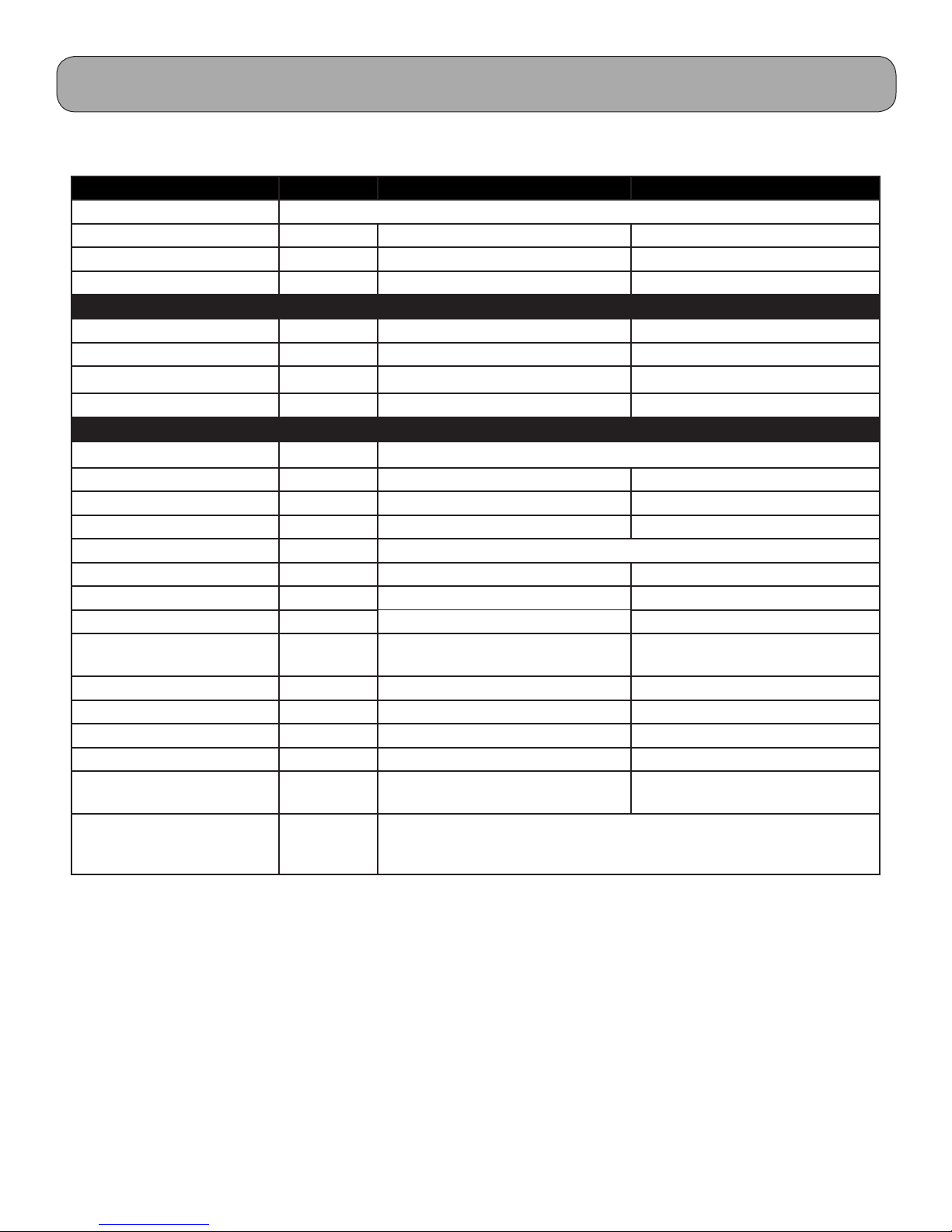
Physical & Electrical Data, cont.
Model RIO09HP115V1A RIO12HP115V1A
System Type Heat Pump
Power Supply 115v / 60Hz 115V / 60Hz
Rated Current Cooling Amps 9.0 15.0
Rated Current Heating Amps 9.5 15.5
System Performance
Cooling Cap (Min/Max) Btu/h 9,000 (3,500-11,000) 11,800 (3,300-12,500)
Heating Cap (Min/Max) Btu/h 9,800 (2,500-11,000) 13,000 (3,400-13,500)
Operating Range - Cooing deg F 64 - 113 64 - 113
Operating Range - Heating deg F 5 - 75 5 - 75
System Specications
Compressor Type DC Inverter-driven Twin Rotary
Sound Pressure - Outdoor dBA 53 55
Net/Gross Weight Indoor lbs 19/26 19/26
Net/Gross Weight Outdoor lbs 75/84 75/84
Condenser Coil Type
Refrigerant/Charge oz R410a /37.5 R410a / 41.1
Line Set Size Liq. - Suction 1/4” - 3/8” 1/4” - 3/8”
Pre-Charged Lineset Ft. Feet 25 25
Additional Refrigerant
charge/additional feet
Max. Total Piping Length Feet 66 66
Max. Elevation Feet 33 33
MCA Amps 13 15
MOCP/Breaker Size Amps 20 25
Wire Size to Outdoor Unit, #
of Wires per Local Code
Wire Size and # of
Conductors from Indoor to
Outdoor unit
oz 0.2 0.2
awg 14* 12*
14awg/4c*
*Comply with National Electric Code or Local Electric Code in selecting proper wire and circuit breaker
size. National Code or Local Code, should supersede wire sizes above.
Note: The manufacturer reserves the right to modify the design and/or change the specications without notice. Please
Note: The manufacturer reserves the right to modify the design and/or change the specications without notice. Please
refer to specic installation manual for current information.
refer to specic installation manual for current information.
5
Physical & Electrical Data, cont.
Model RIO09HP230V1A & 1B
System Type Heat Pump
Power Supply 208-230v / 60Hz 208-230V / 60Hz
Rated Current Cooling Amps 3.9 5.4
Rated Current Heating Amps 3.4 4.7
System Performance
Cooling Cap (Min/Max) Btu/h 9,000 (3,800-11,500) 12,000 (3,300-12,500)
Heating Cap (Min/Max) Btu/h 9,000 (3,300-11,500) 12,000 (3,400-12,500)
Operating Range - Cooing deg F 5 - 109 5 - 109
Operating Range - Heating deg F 5 - 75 5 - 75
System Specications
Compressor Type DC Inverter-driven Twin Rotary
Sound Pressure - Outdoor dBA 49 52
Net/Gross Weight Indoor lb 19/25 20/27
Net/Gross Weight Outdoor lb 64/73 68/77
Condenser Coil Type
Refrigerant/Charge oz R410a / 26.1 R410a / 35.3
Line Set Size Liq. - Suction 1/4” - 3/8” 1/4” - 3/8”
Pre-Charged Lineset Ft. Feet 25 25
Additional Refrigerant
charge/additional feet
Max. Total Piping Length Feet 50 50
Max. Elevation Feet 33 33
MCA Amps 10 10
MOCP/Breaker Size Amps 15 15
Wire Size to Outdoor Unit, #
of Wires per Local Code
Wire Size and # of
Conductors from Indoor to
Outdoor unit
oz 0.2 0.2
awg 14* 14*
14awg/4c*
RIO12HP230V1A & 1B
*Comply with National Electric Code or Local Electric Code in selecting proper wire and circuit breaker
size. National Code or Local Code, should supersede wire sizes above.
Note: The manufacturer reserves the right to modify the design and/or change the specications without notice. Please
refer to specic installation manual for current information.
6
Physical & Electrical Data, cont.
Model RIO18HP230V1A RIO24HP230V1A
System Type Heat Pump
Power Supply 208-230v / 60Hz 208-230V / 60Hz
Rated Current Cooling Amps 7.9 11.5
Rated Current Heating Amps 11.8 13.0
System Performance
Cooling Cap (Min/Max) Btu/h 18,000 (4,500-21,000) 22,000 (6,400-24,000)
Heating Cap (Min/Max) Btu/h 19,200 (4,000-23000) 24,200 (4,100-26,600)
Operating Range - Cooing deg F 5 - 109 5 - 109
Operating Range - Heating deg F 5 - 75 19 - 75
System Specications
Compressor Type DC Inverter-driven Twin Rotary
Sound Pressure - Outdoor dBA 56 53
Net/Gross Weight Indoor lb 27/35 33/44
Net/Gross Weight Outdoor lb 106 / 117 115 / 126
Condenser Coil Type
Refrigerant/Charge oz R410a / 45.9 R410a / 54.7
Line Set Size Liq. - Suction 1/4” - 1/2” 1/4” - 1/2”
Pre-Charged Lineset Ft. Feet 25 25
Additional Refrigerant
charge/additional feet
Max. Total Piping Length Feet 82 82
Max. Elevation Feet 33 33
MCA Amps 15 17
MOCP/Breaker Size Amps 25 25
Wire Size to Outdoor Unit, #
of Wires per Local Code
Wire Size and # of
Conductors from Indoor to
Outdoor unit
oz 0.2 0.2
awg 14* 14*
14awg/4c*
*Comply with National Electric Code or Local Electric Code in selecting proper wire and circuit breaker
size. National Code or Local Code, should supersede wire sizes above.
Note: The manufacturer reserves the right to modify the design and/or change the specications without notice. Please
refer to specic installation manual for current information.
7
Product Introduction
System Overview
e RIO Ductless split heat pumps are single zone
units available in size from 9000 btuh to 24,000 btuh
providing heating and cooling. All comfort settings
are controlled by a remote control. e RIO unit has
many features to enhance comfort and eciency. e
operation of these features will be explained later in
this service manual.
Superior inverter technology is used to control
capacity while maintaining maximum eciency.
e RIO systems are equipped with G10 inverter
technology providing precise control over the
compressor frequency based on operating pressures
and temperatures. Should an abnormal condition
occur, the soware will adjust the compressor
frequency or shut down the system indicating the
appropriate fault.
Indoor Display
e indoor unit contains a digital display, which
will indicate the current fault. e evaporator,
swing motors, fan motors and circuit board are also
components of the indoor unit. e indoor units have
a on/o switch to bypass the remote control if lost or
batteries fail. is will be explained later in this service
manual.
e systems require R410A and are pre-charged for 25’
of lineset. Please refer to your installation manual for
additional charge for linesets longer than 25’.
e maximum allowable line li and distances vary
by model, please refer to the charts in the manual for
proper lineset applications.
e systems use a PVE oil and should require no
additional oil. All RIO units utilize an Oil Return
Mode which will return oil to the compressor should
the need arise.
Circuit Board with
G10 Technology
8
Compressor
Refrigeration Cycles and Components
Refrigeration Components
Indoor Unit
Temperature
Sensor
Heat Exchanger
Strainer
Outdoor Unit
Heat
Exchanger
Temperature
Sensor
Electronic Expansion
Val ve
Accumulator
Compressor
Inverter
Compressor
4-way
Discharge Sensor
Note:
Component locations may vary depending on models.
9
Cooling Mode
Cooling Mode
Refrigeration Cycles and Components
Outdoor Unit
Strainer
Indoor Unit
Heat Exchanger
Temperature
Sensor
Strainer
Temperature
Sensor
*Electronic
expansion
valve
Accumulator not
Exchanger
on all sizes
Heat
Compressor
Inverter
4-way
4-way
valve
valve
Discharge
Silencer
Discharge
Temperature
Sensor
10

Refrigeration Cycles and Components
Cooling Mode
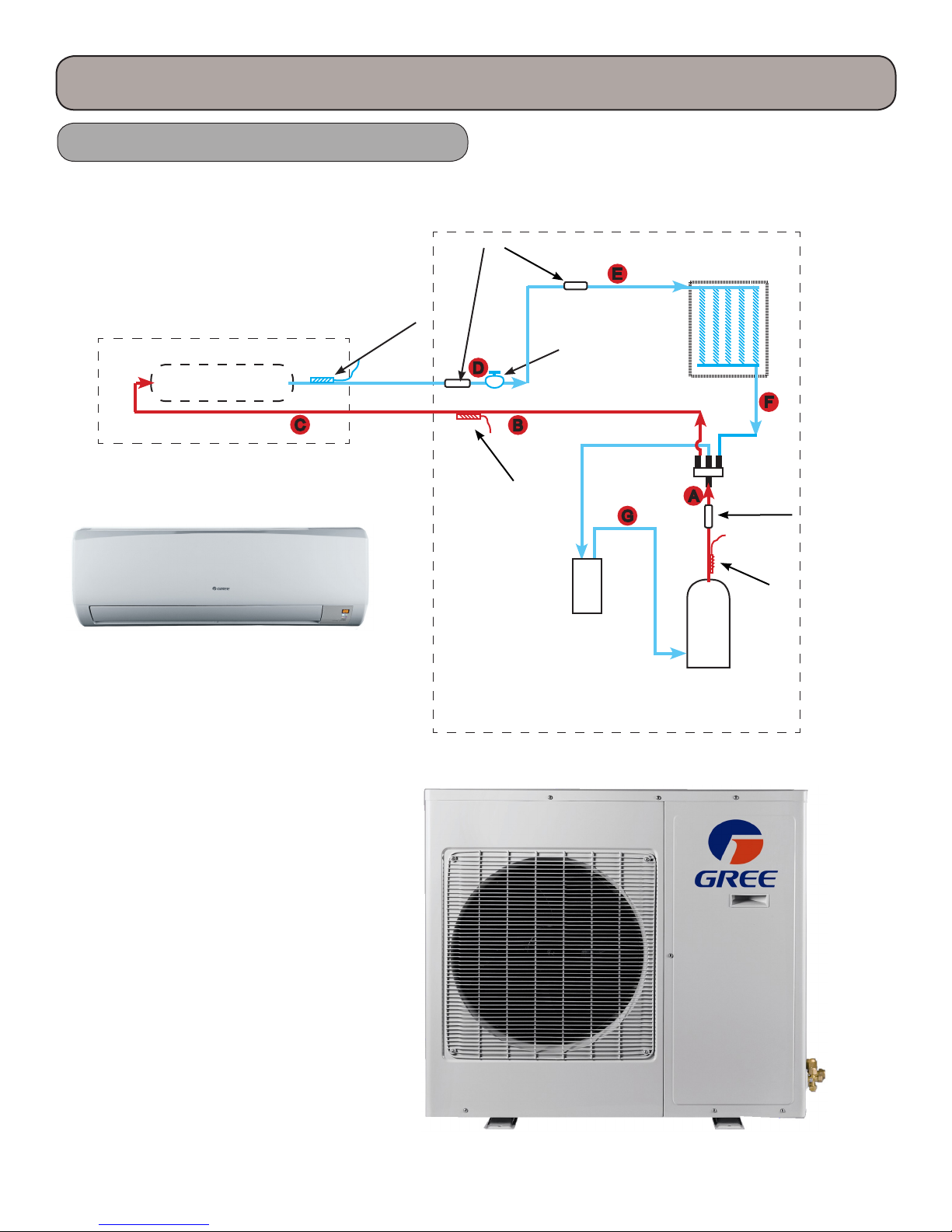
A. Hot gas is discharged from the compressor. e temperature of the gas is monitored by the Discharge
Temperature sensor and sent to the outdoor control panel.
B. e hot gas is directed through the 4-way valve, then enters the outdoor coil. e hot gas will be slightly
subcooled, however there are no pressure ports to take measurements.
C. e subcooled liquid will enter the lter to remove contaminates.
D. e subcooled liquid will enter the metering device and regulate the superheat level. e adjustment process
and compressor speed are controlled by the outdoor circuit board.
E. e refrigerant leaving the metering device will be in a low pressure/temperature saturated state. is cold
saturated refrigerant will move through the coil absorbing heat. is liquid will ash to a vapor and will be
superheated to about 10 degrees F. Since this tubing is cold, it must be insulated.
F. e superheated vapor will be returned to the outdoor unit’s 4-way valve.
G. e refrigerant will ow to the accumulator (not all models will have an accumulator) where liquid and vapor
are separated.
H. e refrigerant will ow to the compressor and complete another refrigeration cycle.
e control board will monitor the temperature and pressures and adjust the frequency of the compressor. ere
are no pressure charts to evaluate temperature or pressures.
11
Heating Mode
Refrigeration Cycles and Components
Outdoor Unit
Filter
Indoor Unit
Heat Exchanger
Temperature
Sensor
Temperature
Sensor
*Electronic
expansion
valve
Accumulator not
Exchanger
on all sizes
Heat
Compressor
Inverter
4-way
4-way
valve
valve
Discharge
Silencer
Discharge
Temperature
Sensor
12

Refrigeration Cycles and Components
Heating Mode
A. Hot gas is discharged from the compressor. e temperature of the gas in monitored by the Discharge
Temperature sensor and sent to the outdoor control panel.
B. e hot gas is directed through the 4-way valve to the appropriate indoor coil making the line a hot gas line.
C. e hot gas will enter the indoor coil and condense to a saturated mix as it travel through the coil and will be
slightly subcooled.
D. e refrigerant returns to the outdoor unit through the lter, then through the metering device reducing the
refrigerant to a low pressure liquid and will maintain the proper superheat.
E. e cold refrigerant will travel through the outdoor coil (evaporator) and will pickup heat from the outdoor
air. is will cause the cold saturated refrigerant to ash to a saturated mixture which will be superheated to
10 degrees F.
F. e superheated vapor will travel through the 4-way valve to the accumulator which will prevent liquid
oodback.
G. e superheated gas will enter the compressor for another refrigeration cycle.
e control board will monitor the temperature and pressures and adjust the frequency of the compressor. ere
are no pressure charts to evaluate temperature or pressures.
13
Indoor Unit Components
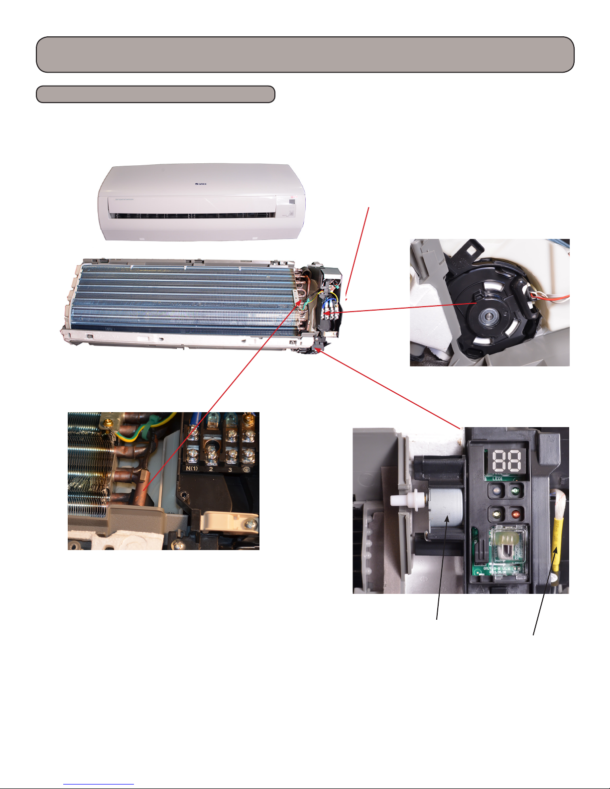
Indoor Unit Components
RIO 12,000 btuh model
Other RIO models may very slightly.
Indoor Circuit
Board
Indoor Tube ermistor
Fan Motor
Swing Motor
Ambient
Temperature
Sensor
Note:
Component locations may vary depending on models.
14
Outdoor Unit Components
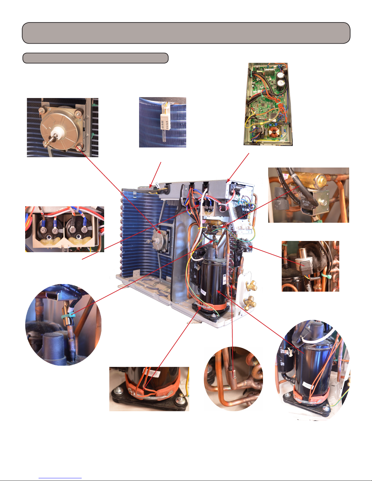
Outdoor Unit Components
RIO 12,000 btuh Outdoor Unit
Other RIO models may very slightly.
Outdoor Fan
Capacitors
Outdoor Sensor, (mounted
on outside of coil)
AP1 Board
4-Way Valve
Expansion Valve
Exhaust Temp
Sensor
Crankcase Heater
Note:
Component locations may vary depending on models.
Outdoor Tube
Sensor
Compressor
15
Basic & Protection Functions
Basic Functions
e compressor should stay o for at least 3 minutes before starting the unit. e compressor circuit has a 3 minute delay if
the compressor is de-energized during a run cycle. If the compressor starts from a de-energized cycle, there will be no time
delay. e compressor has a minimum runtime of 6 minutes regardless of room temperature.
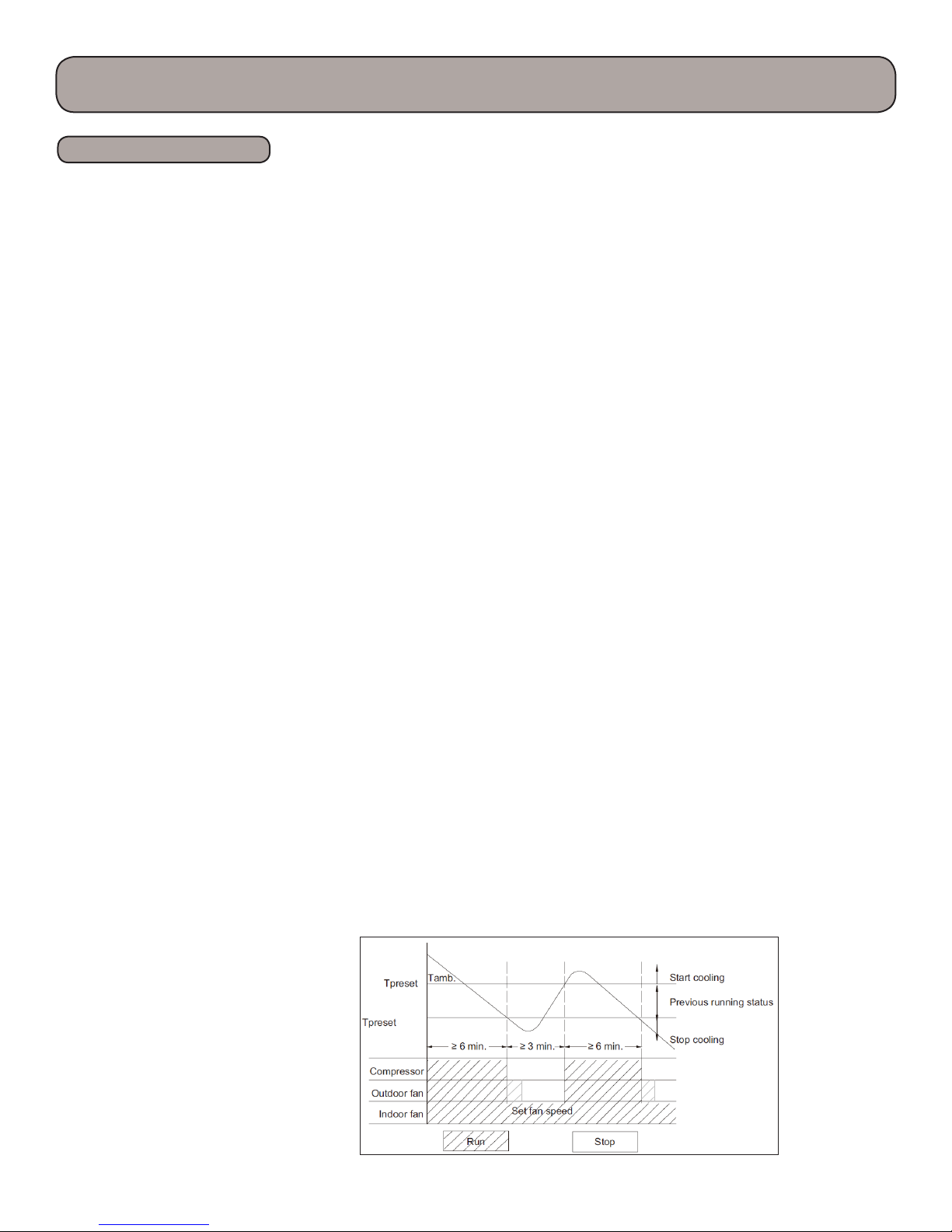
1) Cooling Mode
Cooling Process
When the indoor ambient rises 4 F above the preset temperature from a stopped state, the unit will start the cooling cycle.
e outdoor fan and compressor will start. e indoor fan will run continuously at the selected speed. e outdoor unit
will monitor the appropriate temperatures and pressure and adjust the compressor speed and the EEV as required. If the
indoor ambient is > 4 F than the preset temperature, the compressor will increase the frequency; < 4 F the compressor
will begin reducing the frequency. e EEV will be closed on indoor units with no cooling requirement. e G10
technology will control compressor speed based on indoor load and compressor amperage. When the indoor temperature
is satised, the compressor will stop, then 30 seconds later the outdoor fan will stop. When the cooling mode transfers to
heating mode, the 4-way valve will be energized aer a two minute compressor delay.
Evaporator Freeze Protection
e soware will monitor the indoor evaporator coil form freezing.
e following will occur 6 minutes aer the compressor has been operating in the cooling or dry mode:
If the evaporator temperature drops below 36 F, the compressor will operate at a reduced frequency. If the evaporator
is below 30 F for 3 minutes, the compressor will stop, 30 seconds later the outdoor fan will stop. In cooling mode, the
indoor fan and swing motor will remain on. If the evaporator temperature is >= 50 F and the compressor is o for at least
3 minutes, the compressor will resume its normal operation state.
Overcurrent Protection
e soware will monitor the compressor current to maintain it in a safety and reliable operating range.
If the total current is greater than the rating, the compressor will stop; the outdoor fan will continue to run for 30 seconds,
then stop.
2) Dry Mode
Drying Process
is feature will not take the place of a dehumidier, it is intended to dry the lter and slightly cool the air. If the indoor
ambient temperature is greater than the preset temperature, the unit will enter the cooling and drying mode, in which
case the compressor will operate and the indoor fan will run at a low speed. When the indoor ambient temperature is at or
below the preset temperature, the unit will operate in it previous running state. When the indoor ambient drops to more
than 4 F below the preset temperature the compressor will stop running, then 30 seconds later the outdoor fan will stop,
the indoor fan will run at low speed.
- 2 F
60 Sec 60 Sec
30 Sec 30 Sec
16
Basic & Protection Functions
Basic Functions
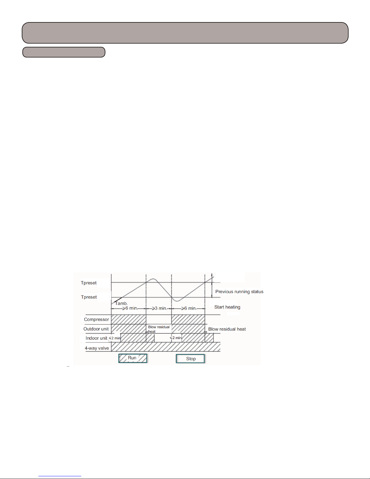
3)Heating Mode
Heating Process
When the indoor ambient drops 4 F below the preset temperature, the unit will start the heating cycle. e outdoor
fan, compressor and 4-way valve will operate. e indoor fan will operate in the “Cold Air Prevention” mode in which
the indoor fan will have a 2 minute delay aer the call for heating. e indoor evaporator coil temperature must reach
104 F before the indoor fan will start, this will prevent cold air from discharging from the indoor coil. When the indoor
evaporator coil temperature is > 104 F, the indoor fan will operate at low speed for 1 minute. With 1 minute of operation
or 2 minutes of no fan operation and the indoor evaporator coil temperature is > 108 F, the indoor fan will operate at its
preset condition.
If the indoor ambient temperature is < 9 F and > 2 F of the preset temperature, the unit will run in its original mode of
operation.
If the compressor is running and the mode is changed from heating to cooling, the compressor will stop, the 4-way valve
will be de-energized 2 minutes later, the outdoor fan will stop aer a 1 minute delay.
If the indoor ambient temperature is >= 9 F than the preset temperature, the compressor will stop and the outdoor fan will
stop aer a 30 second delay. e indoor fan will continue to operate at its preset mode.
e G10 technology will determine compressor frequency based on ambient temperatures.
+9 F
+ 2 F
Stop heating
17

Basic & Protection Functions
Basic Functions
Defrost Process
You may force a defrost in heat mode by pressing the “+” and “-” buttons alternately three times within 5
seconds.
1) e unit will enter defrost when the following conditions are met:
A. Outdoor ambient <= 41 F
B. Compressor had accumulated more than 3 hours of operation in heating mode
C. e outdoor coil <= 32 F
Note: e compressor runtime will be cleared when the outdoor ambient is > 41 F or when the compressor has started
up aer changing to cooling or drying mode and defrost has nished. e runtime will not be cleared when the unit has
stopped aer reaching the setpoint temperature, a protection fault or changing to fan mode.
ere are 3 perimeters used in the defrost algorithms, Outdoor ambient(T
a calculated T
T
compensation
D. Aer power-up, for the rst defrost T
E. T
F. T
compensation
is calculated by the following:
tube > 36 F then T
outdoor
tube <= 36 F then T
outdoor
compensation = 32
compensation = 32
compensation = 37
F
F
F
ambient), Outdoor tube(T
outdoor
outdoor
tube) and
2) When heating has operated continuously for 45 minutes, or accumulated for 90 minutes, the unit will enter defrost
mode in 3 minutes aer meeting any of the conditions below:
A. Outdoor ambient >= 41 F and outdoor coil <= 28 F
B. 28 F <= T
C. 23 F <= T
D. 14 F <= T
ambient< 41 F, “Toutdoortube -Tcompensation ≤ 21F”
outdoor
ambient < 28 F <= Toutdoortube -Tcompensation ≤ 18F”
outdoor
ambient < 23 F , T
outdoor
outdoor
tube -T
compensation
<= (T
ambient - 37 F)
outdoor
E. Toutdoorambient < 14 F, Toutdoortube -Tcompensation <= (Toutdoorambient - 37 F)
3) During defrost, if run time for the compressor does not reach 3 minutes, the defrost cycle will not start for the next
2 hours. At that time the compressor stops operation and 30 seconds later the outdoor fan will stop. 30 seconds aer
this the 4-way reversing valves will de-energized. Following another 30 second delay, the compressor will increase its
compressor speed for defrosting. Defrosting will last for 450 seconds or until the T
tube >= 50 F, at this temperature
outdoor
the compressor will decrease it compressor speed for 30 seconds, then will stop. In another 30 seconds the 4-way valve will
energize, the 60 seconds later the compressor and outdoor fan will start. e compressor speed for defrosting will be 85hz.
During Defrost mode, a “H1” will be displayed on the indoor front panel display indicating the user selected mode has
been overridden and the system is performing a outdoor coil defrost operation.
4) Defrost Sequence:
When a defrost condition has been met, the compressor will stop, all expansions valves will open fully, the outdoor fan will
stop 40 seconds aer the compressor stops. e 4-way valve will reverse direction (cooling mode) , then the compressor
will start and enter the defrost frequency. e control, board along with ambient sensors will calculate defrost time.
5) Oil Return:
Oil return condition can be met if the unit operates at a low frequency for an extended time. e indoor display will
indicate “H1” for this condition and is a normal procedure.
18

Basic & Protection Functions
Basic Functions
Cold Air Prevention (Heating mode with compressor running)
e system guards against discharging cold air in heating mode. It will delay the indoor fan until the evaporator coil has
warmed up to discharge warm, comfortable air into the room.
1) When the T
ambient < 75 F and the T
indoor
to run at low speed aer a 2 minute delay. is will reduce cold air upon heating startup. Within 2 minutes, if
T
tube > 104 F, the indoor fan will run at low speed. Aer 1 minute of operation, the fan will run at the preset fan
indoor
mode. Within 1 minute of low speed operation or 2 minutes of no fan operation, with the T
run at the preset mode.
tube <= 104 F with the fan in a stopped state, the indoor fan will begin
indoor
tube > 108 F, the fan will
indoor
2) If the T
ambient >= 75 F and the T
indoor
at the preset mode. Aer 1 minute of low speed operation, if the and the T
tube <= 108 F the indoor fan will run at low speed for 1 minute than run
indoor
tube > 108 F the fan will operate at its
indoor
preset mode.
Note:
e T
Overcurrent and Speed Protection (Total Current = I
ambient in 1 & 2 above refers to the unit going into the heating mode coming out of defrost.
indoor
)
total
e soware will monitor the compressor current draw and adjust the compressor speed in order to maintain the inverter and
compressor in a safety and reliable operating range.
A. If I
B. If I
C. If I
D. If I
<= 13a, an increase in frequency will be allowed
total
>= 15a, increasing the frequency is not allowed.
total
>= 17a, the compressor will decrease its frequency
total
>= 19a, the compressor will stop and the indoor fan will stop aer 30 seconds.
total
4)Fan Mode
Under this mode, the fan will run at the preset speed and the outdoor fan, compressor and 4-way valve will stop.
5)Auto Mode
Auto Mode Process
Setting the auto mode will run the unit in heat or cool automatically depending on T
1)Operating Parameters
A. If the T
B. If the T
C. When the T
ambient >= 79 F the unit will operate in cooling mode. e set temperature is 77 F.
indoor
ambient <= 72 F the unit will operate in heat mode. e set temperature is 68 F.
indoor
ambient <= 73 F and >= 77 F, the unit will operate in the previous state. If it is energized
indoor
for the rst time, it will run in Fan mode
D. In auto mode, the cooling frequency will be the same as the cooling only mode and the heating frequency will
be the same as the heating only mode.
2) Protection
A. In cooling operation, protection is the same as the cooling only mode
B. In heating operation, protection is the same as the heating only mode
C. When the indoor ambient temperature changes, the operation mode will be automatically selected. Once started
the compressor will have a 6 minute runtime.
indoor
ambient
19

Basic & Protection Functions
Protection Functions
Common Protection Functions and Fault Displays
Coil High Temperature Protection
T
= measured temperature of outdoor coil in cooling mode, measured temperature of indoor coil in heating mode.
tube
1) Outdoor Coil High Temperature Protection - In cooling mode the soware will monitor the outdoor coil for an
abnormal high temperature condition.
A. If T
B. If T
C. If T
D. If T
2) Indoor Coil Temperature Protection - In heating mode the soware will monitor the indoor coil for an abnormal high
temperature condition.
A. If T
B. If T
C. If T
D. If T
<= 126 F, the unit will return to its original operation state
tube
>= 131 F, frequency rise is not allowed
tube
>= 136 F, the compressor will run at reduced frequency
tube
>= 144 F, the compressor will stop and the indoor fan will operate at preset speed
tube
<= 122 F, the unit will return to its original operation state
tube
>= 127 F, frequency rise is not allowed
tube
>= 133 F, the compressor will run at reduced frequency
tube
>= 140 F, the compressor will stop and the indoor fan will blow residual heat and then stop
tube
3) Compressor Discharge Temperature Protection
e soware will monitor the compressor discharge for an abnormal high temperature condition.
A. If T
B. If T
C. If T
D. If T
>= 208 F, frequency rise is not allowed
tube
>= 217 F, the compressor will run at reduced frequency
tube
>= 230 F, the compressor will stop
tube
<= 194 F and the compressor has been off for at least 3 minutes, the compressor will resume operation
tube
4) Compressor High Pressure Protection (Not available on 115v 9k & 12k models)
When the high pressure switch is detected for 6 seconds or more, the compressor will stop and can only be started by
powering o the unit. Dirty coils, refrigerant overcharge and outdoor fan problems can cause this fault.
5) Compressor Phase-lacking Protection
If one of the compressor phases are detected open before startup, the compressor will enter phase-locking protection.
e malfunction will be cleared aer 1 min, then the unit will try a restart. If an error has been detected for 6 times
continuously, the compressor will lock out and will need to have power cycled. e errors will be cleared aer the
compressor has run for 7 minutes continuously.
6) Module Protection (IPM)
Under module protection mode, the compressor will stop. When the compressor remains o for 3 minutes, the compressor
will resume operation. If the module protection occurs six times in succession, the compressor will remain o. Power will
need to be cycled to start unit. is is a thermal protection for the indoor module.
7) DC Buss Voltage Protection
e soware will monitor the DC bus voltage.
If voltage on the DC Bus is below 150 or over 420v, the compressor will stop and the outdoor fan will stop in 30 seconds.
When the voltage on the DC bus returns to normal and the compressor has been o for 3 minutes, the compressor will
resume its operation.
20

Basic & Protection Functions
Protection Functions
8) Communication Fault
If the unit fails to receive correct signals for a 3 minutes, communication fault will occur and the whole system will stop
and a “E6” will be displayed on the front panel of the indoor unit.
21
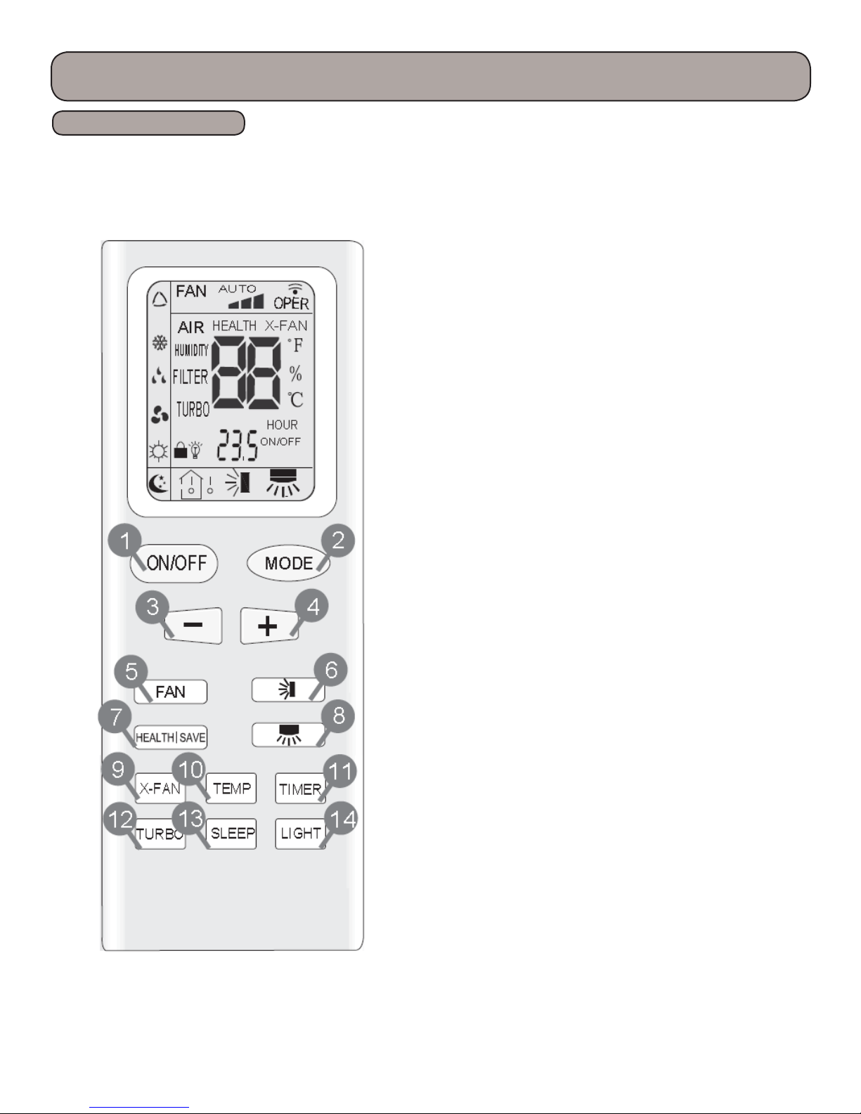
Remote Buttons
Remote Control Operation
Note:
is remote control is used in other models and some
features may or may not be available. Consult the
owners manual for specic features for your model.
ere should be no obstructions between the remote
control and the indoor unit for proper operation. Keep the
remote from direct sunlight or any source that generates
heat, keep clean and dry. Change batteries frequently.
Note:
For detailed explanation of the functions, refer to the
“Other Controls” section of this manual for your model.
Button Identication
e function and operation of each button will be
explained later in this manual under Product Functions.
1. On/O button
2. Mode, press to select desired operation
3. Decrease temperature
4. Increase temperature
5. Fan, press to select fan speed
6. Swing angle button (up & down)
7. Health/Save button, not available on all models
8. Swing angle button (le & right)
9. X-Fan button
10. Temperature Display
11. Timer Button
12. Turbo Fan Button
13. Sleep Button
14. Light Button
Press “mode” and “-” buttons to switch between
Fahrenheit & Centigrade
Press “-” & “+” to lock control
22
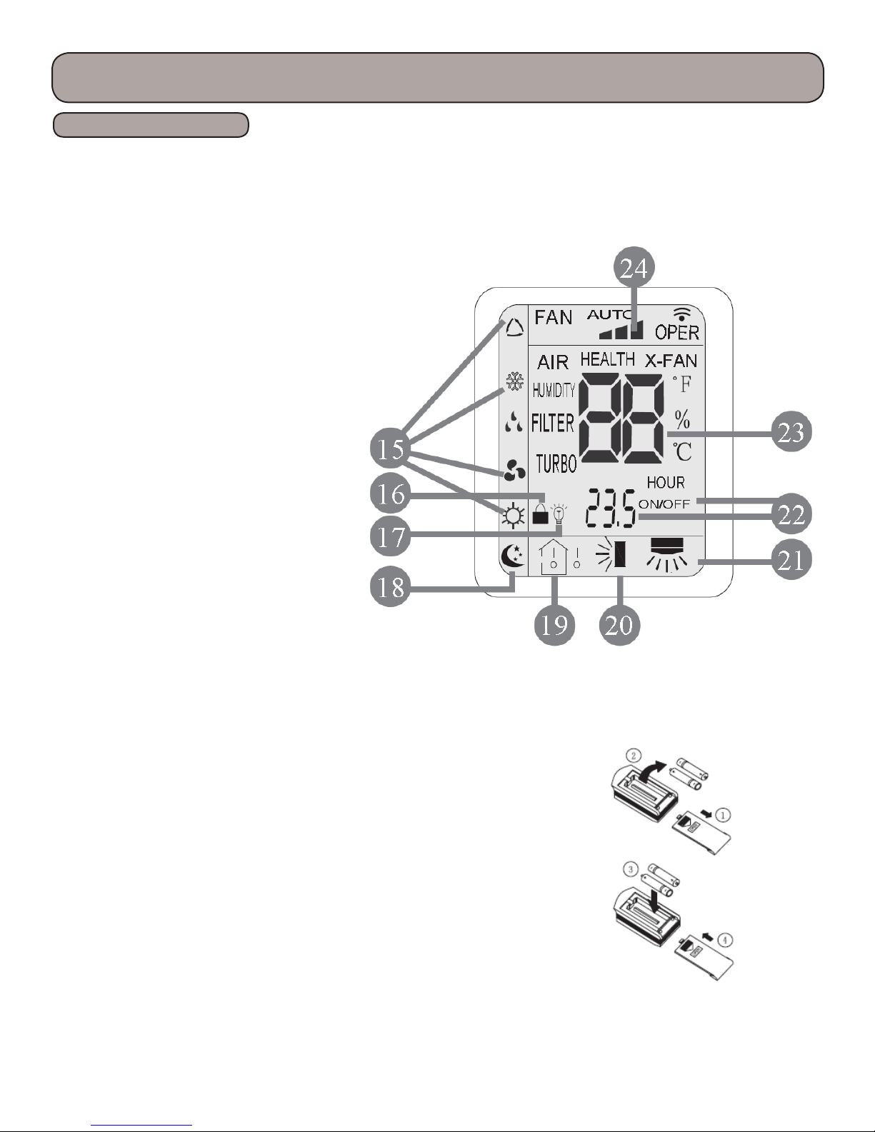
Display Icons
15. Mode icons
16. Lock icon
17. Light icon
18. Sleep icon
19. Temperature icon
20. Up & down swing icon
21. Le & right swing icon
22. Set time icon
23. Digital display
24. Fan speed icon
Remote Control Operation
Replacing Batteries:
1. Locate the battery cover on the back of the remote.
2. Slide the cover downward.
3. Make sketch of battery polarities, then replace with
two “AAA” batteries.
4. Replace cover.
23

Product Introduction
Remote Control Functions
1)On/O
e on-o state will change with each button press.
2) Mode Setting
Each time you press this button, a mode is selected in a sequence that goes from AUTO,
COOL, DRY, FAN,and HEAT
Aer energization, AUTO mode is defaulted. In AUTO mode, the set temperature will not
be displayed on the LCD, and the unit will automatically select the suitable operation
mode in accordance with the room temperature to make indoor room comfortable.
3)”-” Button
Press this button to decrease set temperature. Hold it down for above 2 seconds to
rapidly decrease set temperature. In AUTO mode, set temperature is not adjustable.
4)”+” Button
Press this button to increase set temperature. Hold it down for above 2 seconds to
rapidly increase set temperature. In AUTO mode, set temperature is not adjustable.
5) Fan
is button is used for setting fan speed in the sequence that goes from AUTO, low, medium, high, then back to
auto.
6) Up & Down Swing
Press button to start or stop up & down swing function. e remote controller defaults to simple swing
condition. Press + button and button at the same time at unit OFF to switch between simple swing and
static swing; blinks for 2 seconds. In static swing condition, pressing
louver positions. If the unit is turned o during swing operation,the louver will stop at present position.
button, the swing angle up & down
7) Health Save
Press HEALTH part of this button to turn on or o HEALTH function.(only for some model)
Pressing SAVE this button, SE is displayed and the unit goes into SAVE operation mode. Press SAVE button
again to cancel SAVE function. During SAVE operation , the temperature and fan speed is not adjustable.
8) Le & Right Swing
Press button to start or stop le & right swing function. e remote controller defaults to a simple swing
position.
Press + button and button at the same time at unit OFF to switch between simple swing and static swing;
blinks for two seconds
In static swing position, pressing button the swing angle will change positions.
24

Product Introduction
Remote Control Functions
9) X-Fan
Allows fan to run aer cooling cycle to dry o the coil and inhibit the growth of bacteria and mildew. Works
with “Auto” mode.
10)Temp Button
Toggles the display between set temperature, indoor temperature and outdoor temperature.
11) Timer On Button
Press TIMER button at unit ON to set TIMER OFF; HOUR OFF blinks. Press TIMER button at unite OFF to set
TIMER ON; HOUR ON blinks. In this case, pressing + or - button changes time setting. Holding down either
button rapidly changes time setting (time setting range 0.5 - 24 hours). Press TIMER button again to conrm
setting; HOUR ON/OFF stops blinking. If there is not any operation of button within 5 seconds during HOUR
ON/OFF blinking, TIMER setting will be canceled.
12) Turbo Button
Boost the cooling or heating airow, allowing the unit to reach the preset temperature in the shortest amount of
time.
13) Sleep Button
Press this button to go into the SLEEP operation mode. Press it again to cancel this
function. is function is available in COOL , HEAT (Only for models with heating
function) or DRY mode to maintain the most comfortable temperature for you.
14) Light Button
Turns the light on the indoor display on and o.
15) Combination of “+” and “-” Buttons
Press “+” and “-” buttons simultaneously to lock or unlock the keypad
16) Combination of “Mode” and “-” Buttons
Press “Mode” and “-” buttons simultaneously will switch between Fahrenheit and Centigrade.
25
Refrigerant Lines Connection, Evacuating and Charging
Refrigerant Lines Preparation &
Connection
The refrigerant lines should be kept sealed until ready to be
connected. Follow the following steps to ensure a quality leak
proof installation:
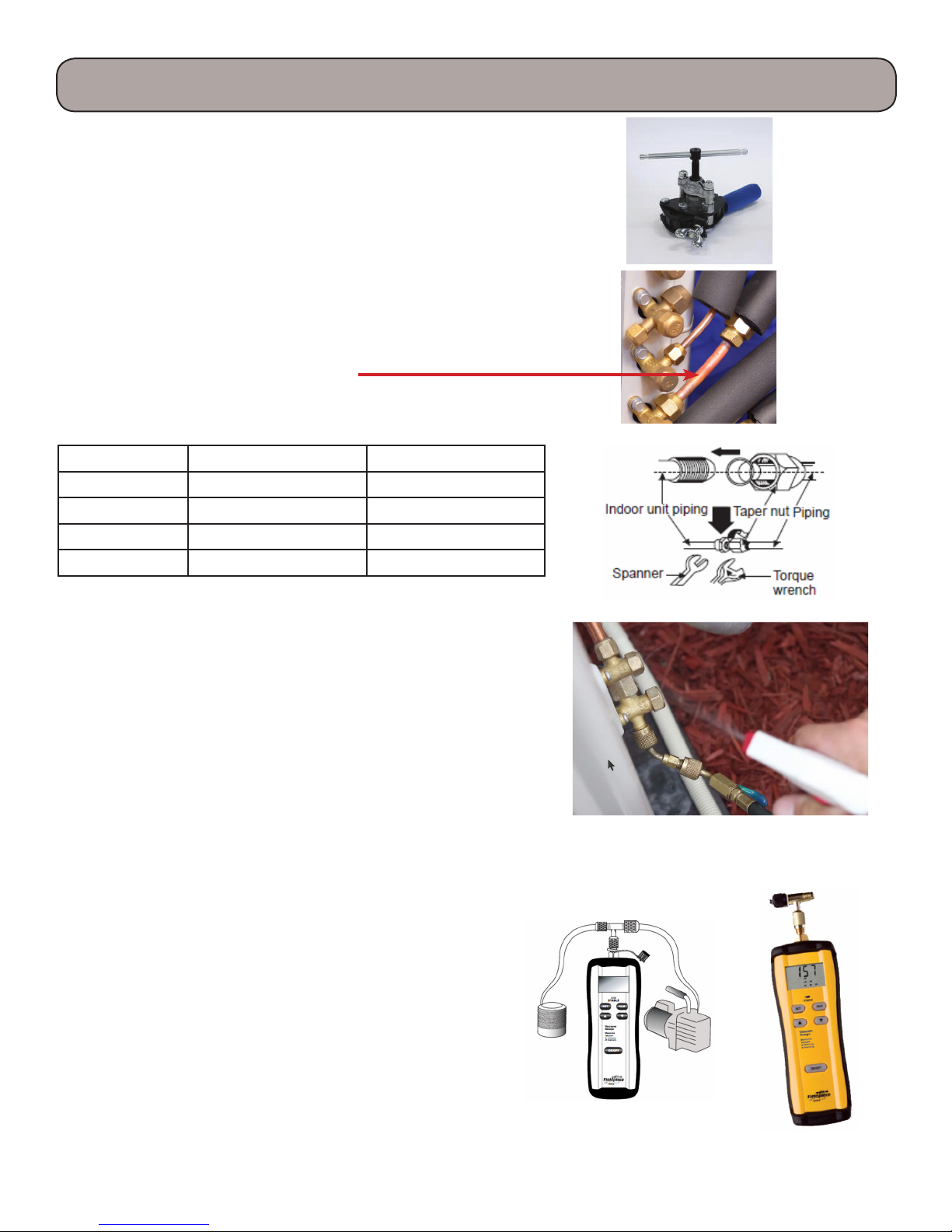
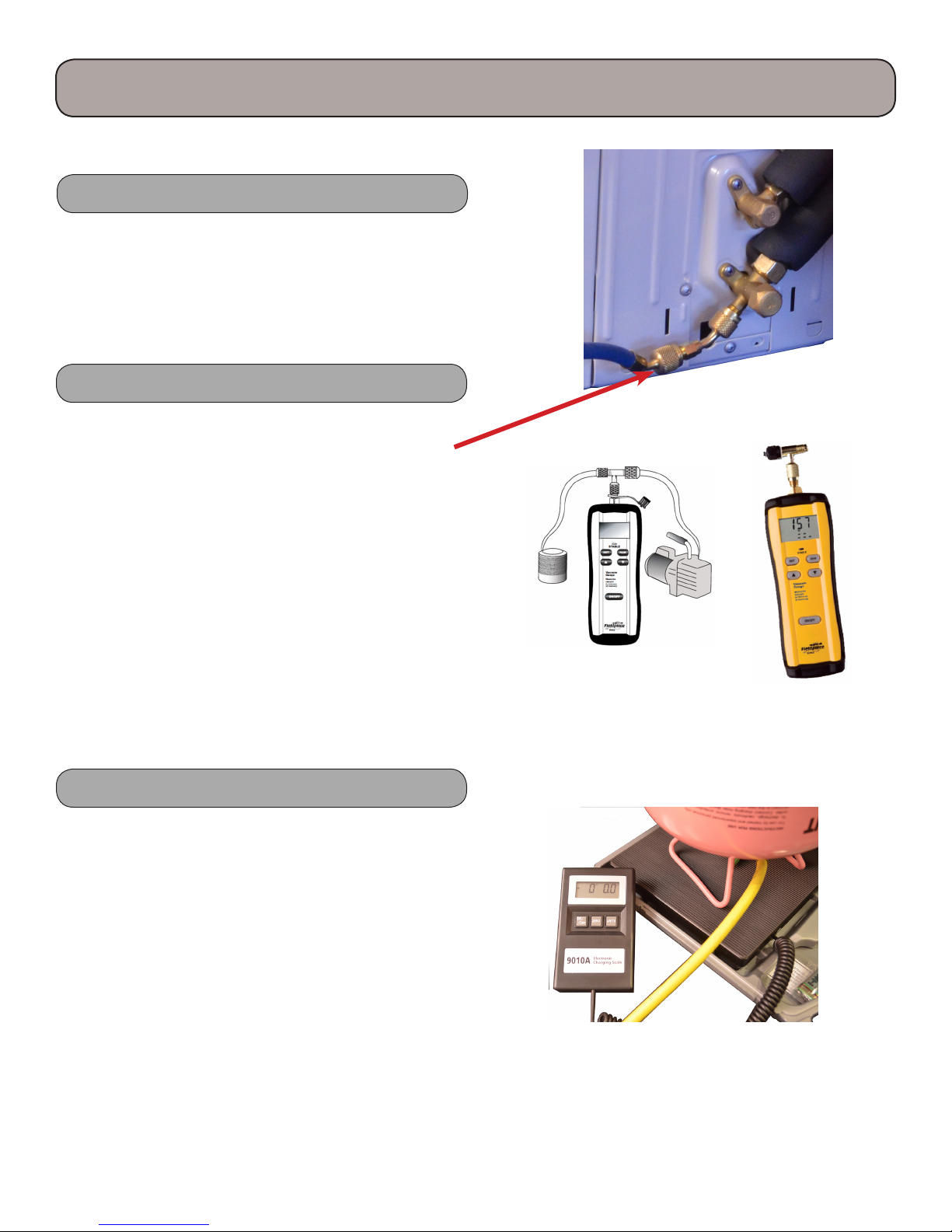
Step 1. Refrigerant Line Connection
Carefully bend and cut the tubing to prepare for aring. Use a
aring tool designed for R410a, following the recommended
manufacturer’s procedure. Tighten the are nut to the
indicated torque by using a spanner wrench and a toque
wrench. Connect the indoor unit rst, then the outdoor unit.
Use the 3/8” to 1/2” are adapter if needed.
Note:
Over tightening are nuts may damage are connections and
may cause leaks.
Tubing Size Torque (foot-pounds) Torque (inch-pounds)
1/4” 10-13 124-159
3/8” 25-31 301-372
1/2” 36-45 434-540
5/8” 50-60 602-726
Step 2. System Leak Check
Refrigerant lines should be pressurized prior to evacuating
system to check for leaks.
Use only dry nitrogen with a pressure regulator for
pressurizing unit. Pressurize with 150 psi of dry nitrogen.
Apply soap and water to check whether the joints are leaky. A
leak detector may also be used for a leakage test.
Hint:
You may want to perform leak testing and evacuation before
wiring to save time, electrical connections can be completed
while your vacuum pump is running.
Step 3. System Evacuation
Note: The outdoor unit contains a refrigerant charge, leave
liquid and gas valves closed.
1. After no leaks have been detected, connect a vacuum
pump to the outdoor unit.
2. Connect appropriate hoses to manifold gauge, vacuum
pump and unit refrigeration connections.
3. Evacuate the system until the micron gauge reads no
higher than 350 microns.
4. Close valve to vacuum pump; if pressure does not rise
above 500 microns after one minute, the evacuation
should be complete.
5. If it does rise, check for leaks and/or evacuate longer.
6. For refrigerant lines longer than 25 feet, refer to
installation instructions chart included with the unit
installation manual for additional charge.
26
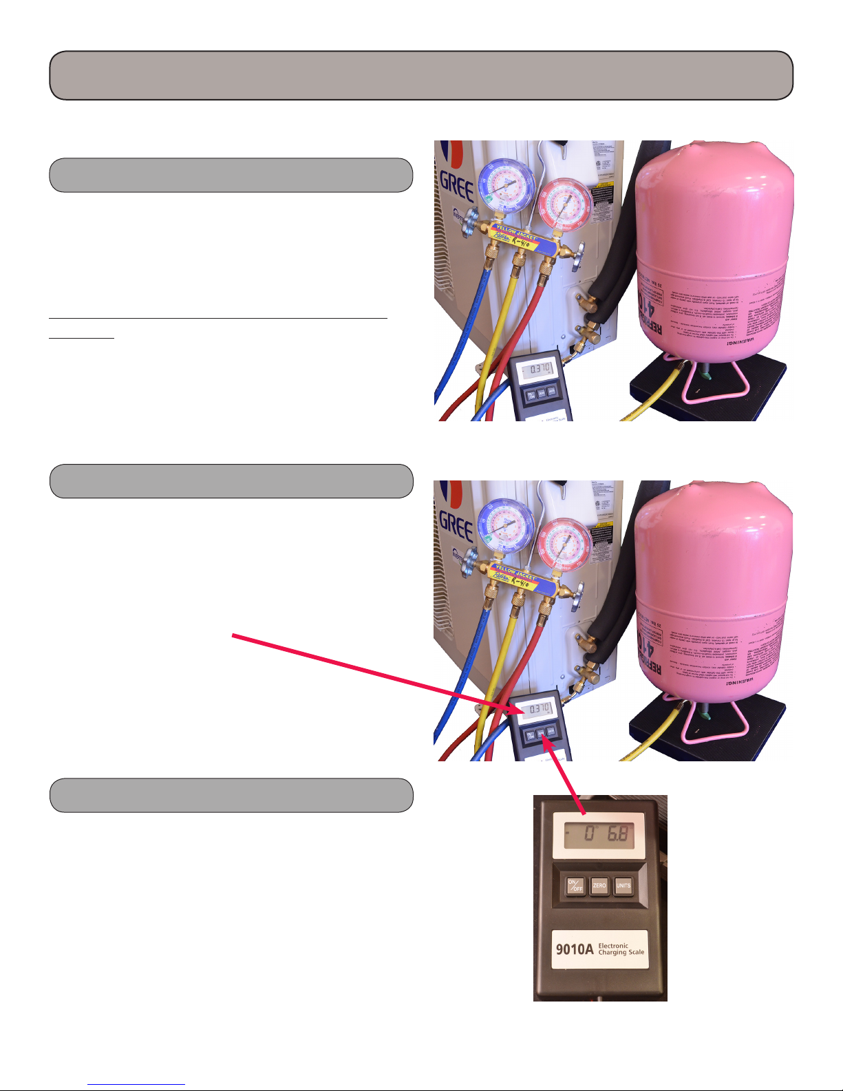
Refrigerant Charging Procedure
Please refer to your units installation manual for proper charge. If your lineset exceeds the chart below for your
model, additional charge may be required. e charge must we weighed in with a refrigerant charging scale.
You can only add additional refrigerant to a new installation. If a low or high charge is suspected, you must
reclaim the refrigerant, then weigh in the correct amount per specications including any additional for long
linesets. It is important to check for leaks before adding refrigerant.
1. Determine addition refrigerant charge.
e RIO single zone units contain a factory charge adequate for up to a total length of refrigerant line as
indicated in the chart below. Additional refrigerant will need to be added for total lengths over the listed length.
Conrm the following chart with your installation manual for additional charge amounts:
RIO09HP115V
1A
Additional Charge 0.2 oz./. 0.2 oz./. 0.2 oz./. 0.2 oz./.
Max Length without
Additional Charge
Factory Charge
Max. Total Piping
Length
Max. Elevation
Additional Charge
Max Length without
Additional Charge
Factory Charge
Max. Total Piping
Length
Max. Elevation
25 . 25 . 25 . 25 .
35.3 oz. 35.3 oz. 26.1 oz. 35.3 oz.
49 . 66 . 50 . 50 .
33 . 33 . 33 . 33 .
RIO14HP230V1ARIO24HP230V
0.2 oz./. 0.22 oz./.
25 . 25 .
45.9 oz. 54.7 oz.
50 . 50 .
33 . 33 .
RIO12HP115V
1A
1A
RIO09HP230V
1A & 1B
RIO12HP230V
1A & 1B
27
Refrigerant Charging Procedure
2. Leak Testing
Follow the procedures for leak testing with nitrogen
prior to adding charge on a new installation or existing
one suspected for leaks. See preceding page.
3. Attach hoses to the unit and vacuum pump
5/16” x 1/4” adapter may be required to connect hose
to port.
Check to insure that the liquid and gas valves are closed
on the unit. Close all valves on your gauge set, then
connect the vacuum pump to your gauge set. Pump
down lineset and indoor unit. is step will be repeated
for all zones.
4. Zero charging scale
Place the refrigerant tank on the charging scale. Open
the tank valve, turn on the scale, then zero the scale.
28
Refrigerant Charging Procedure, cont.
5. Begin adding additional refrigerant
Charging should be completed with the unit o (not
running) and through the liquid side with liquid
refrigerant. If there are no ports on the liquid side, use
the gas side port connection, charging with liquid.
Record the amount of additional charge for future
reference.
6. Charge to the correct weight
If the scale was zeroed with the refrigerant tank on the
scale, the amount added to the system will be a negative
amount since it was removed from the tank. Aer the
proper amount of refrigerant has been weighed in,
close the manifold valve.
7. Remove refrigerant tank
Close the tank valve, then carefully remove the hose
and adapter. Replace the charging port cap back on
the outdoor unit valves. On new installations, open all
liquid and vapor service valves.
29
Installation
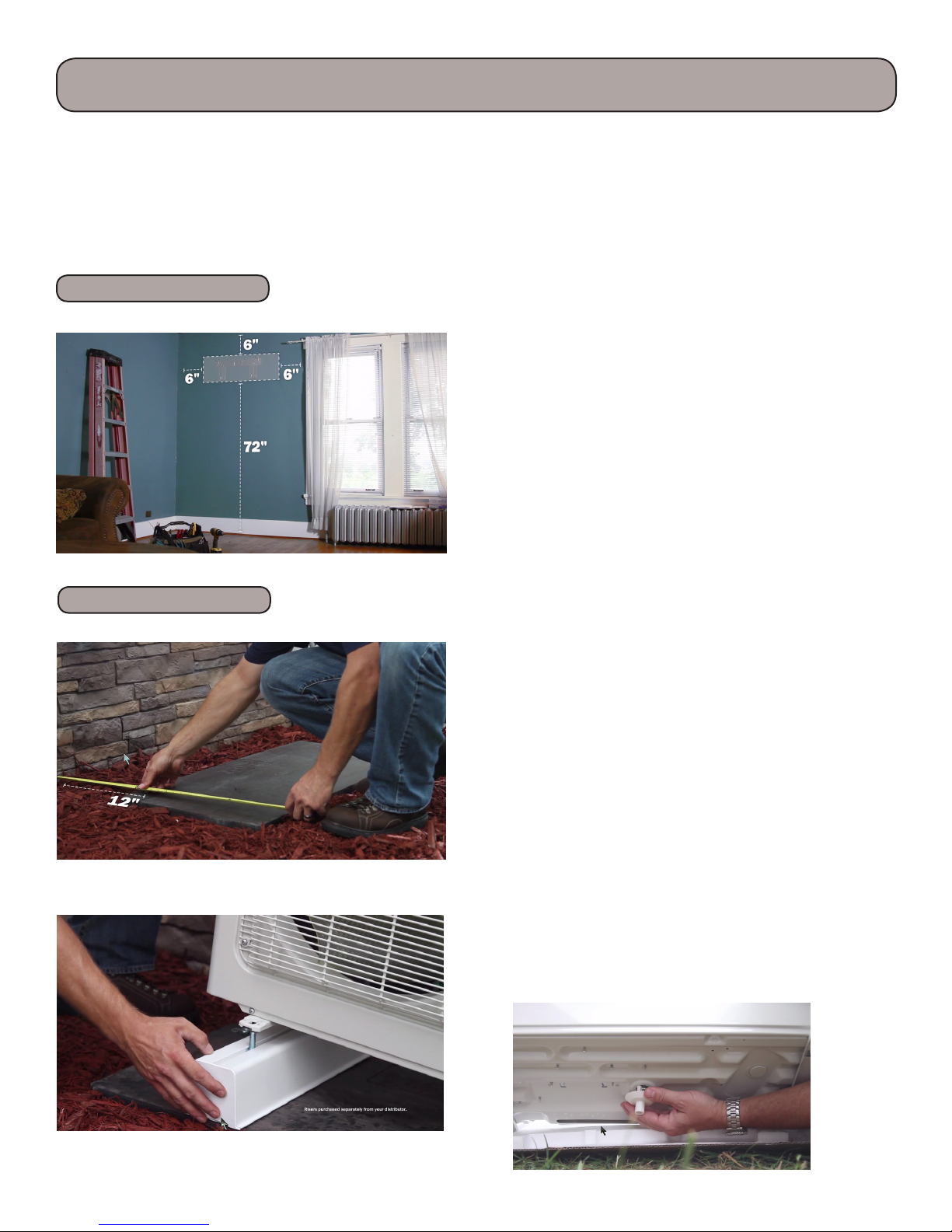
Proper installation site is vital for correct and ecient operation of the unit. Avoid the following sites where:
• Strong heat sources, vapors, ammable gas or volatile liquids are emitted.
• High-frequency electro-magnetic waves are generated by radio equipment, welders and medical equipment.
• e air is contaminated with industrial vapors and oils.
• e air contains sulfurous gas such as in hot spring zones.
• Poor air quality exists.
Indoor Unit
Outdoor Unit
e air inlet and outlet should be away from any
obstructions. Ensure the air will easily circulate through
the entire room.
1. Select a site where the condensate can be easily routed
or consider a condensate removal pump.
2. Select a place where it is out of reach of children.
3. Select a place that has adequate mounting structure,
strong enough to withstand the full weight and
vibration of the unit.
4. Be sure to leave enough space to allow access for
routine maintenance. Refer to unit installation
specications for clearances. Select a place more than
3 feet away from any TV or other electrical appliances
1. Select a suitable site where proper drainage will occur.
2. Select a site where there is sucient ventilation.
3. Select a site where there is no obstruction blocking the
inlet and outlet.
4. e site should be able to withstand the full weight of
the unit.
5. Try to limit expose to direct sunlight or strong winds.
6. Make sure that the outdoor unit is installed in
accordance with the installations instructions, and is
convenient for maintenance and repair.
7. Refer to your outdoor unit installation manual for
maximum lineset lengths and heights. is could be a
factor in determining outdoor location.
8. Select a place where it is out of reach of children.
9. Install Heat Pump legs to allow for proper drainage.
10. Install drain tting in bottom of outdoor unit
30
 Loading...