

Page 1
GAS DRYER
®
Dry-Soft
4 & 6
Operation / Installation Manual
Models: RD-400AU & RD-600AU
This appliance shall be installed in accordance with:
• Manufacturer’s Installation Instructions
• Current AS/NZS 3000, AS/NZS 3500 & AS 5601
• Local Regulations and Municipal Building Codes
This appliance must be installed, serviced and removed by an Authorised Person.
All Rinnai gas products
are A.G.A. certified.
Distributed and serviced in Australia under a Quality
System certified as complying with ISO 9001 by
SAI Global
Page 2
REGULATORY INFORMATION
This appliance must be installed, commissioned and serviced by an Authorised person in accordance
with local gas, electrical and plumbing regulations.
The installation must also comply with these instructions.
The appliances referred to in this manual have been certified by the Australian Gas Association (AGA).
The AGA Certification number is shown on the appliance dataplate.
Keep this manual in a safe place for future referenc e.
WARRANTY
WARRANTY TERMS
The benefits conferred by this warranty are in addition to all other rights and remedies in respect of the product which
you have under the Trade Practices Act and similar State or Territory Laws. Give n instal lation and a ppl ication is in
accordance with the manufacturers specifications and instructions, Rinnai gas d ryers are warranted by Rinnai for
the cost of labour and components in the event of defects arising from faulty materials and/or workmanship in
accordance with the Terms in Table 1 and Warranty Conditions and Exclusions stated in this document and any
additional conditions and exclusions stated in the Operating and/or Installation Instructions for the appliance.
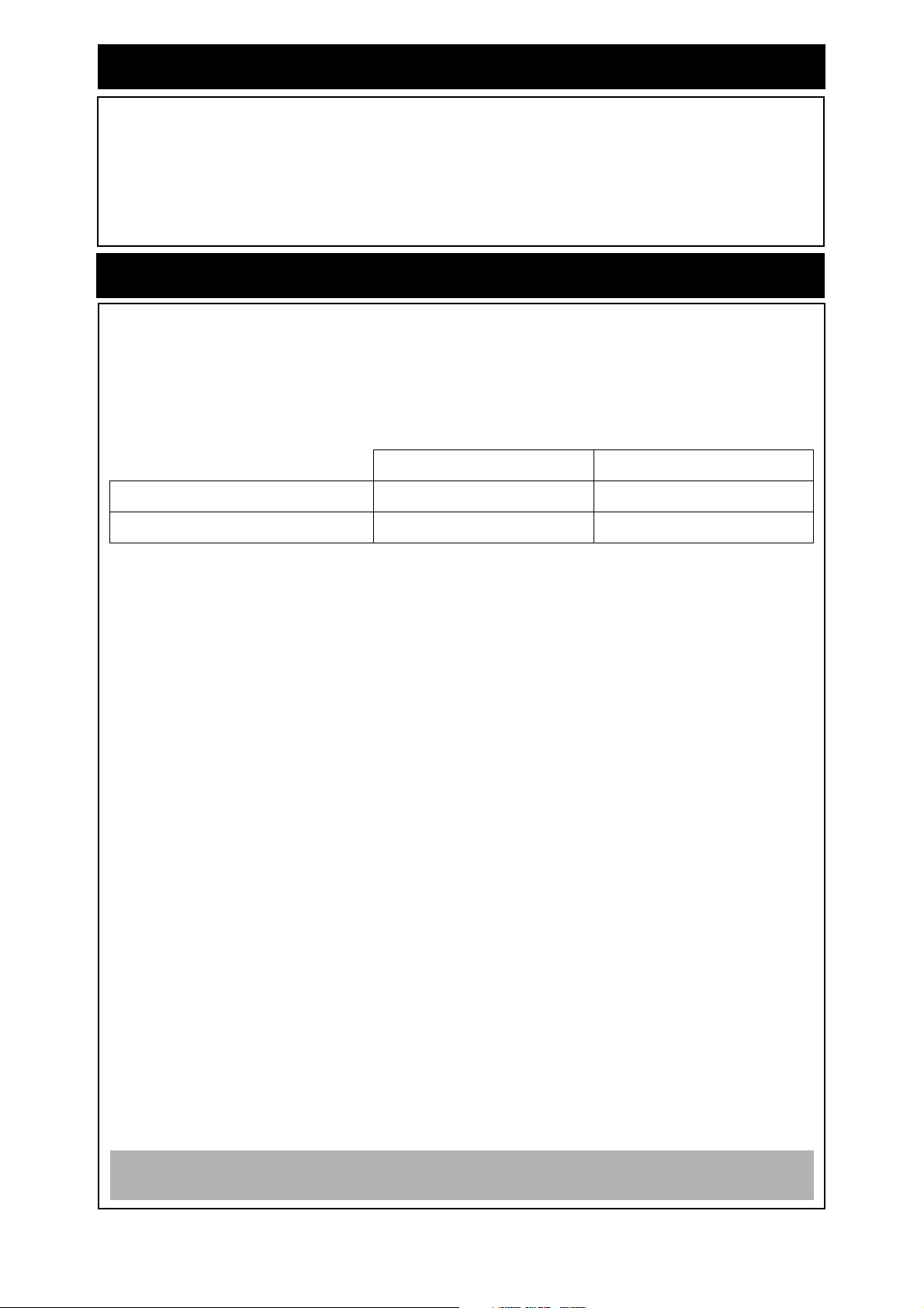
Free Labour Period Free Parts Period
Domestic Use 2 Years 2 Years
Commercial Use 1 Year 1 Year
Table 1 Warranty Terms
Definition of Domestic Use
The warranty periods that are allocated under "Domestic Use" are based on the gas clothes dryer usage of a
typical family and apply only to gas dryers installed in domestic dwellings.
Definition of Commercial Use
The warranty periods that are allocated under "Commercial Use" are for gas clothes dryers installed at premises
such as commercial and industrial buildings, hotels, motels, caravan parks and sporting complexes.
WARRANTY CONDITIONS
1. Dated proof of purchase is required to be shown to the attending service person prior to the commencement
of any warranty work.
2. The gas dryer and components must be installed in accordance with the Manufacturer's Installation
Instructions, current AS 3000, AS 3500 and AS 5601, local regulations and municipal building cod es. Gas
dryers and components must only be installed, commissioned and removed by persons authorised by local
regulations to do so and serviced and repaired by Rinnai approved technicians.
3. The warranty applies only to the components supplied by Rinnai. It does not apply to compo nents supplied
by others, such as isolating valves, electrical switches, pipework, electrical cables and fuses.
4. Where the gas dryer or it's components have not been sited in accordance with the Installation Instructions
or are installed such that normal service access is difficult, a service charge may apply. At the discretion of
the attending service person, if access is deemed dangerous service will be refused. Any work required to
gain reasonable access to gas dryer components may also be chargeable at the discretion of th e attending
service person (for example, removal of cupboards, doors or walls, or the use of special equipment to move
components to floor level).
5. Where a failed component is replaced under warranty, the balance of the original appliance warranty will
remain effective. The replacement part or appliance does not carry a new warranty.
6. Rinnai reserve the right to transfer functional components from defective appliances if they are suitable.
7. Rinnai reserve the right to have the installed product returned to the factory for inspection.
WARRANTY EXCLUSIONS:
1. Accidental damage, acts of God, failure due to misuse, incorrect or unauthorized installations, attempts to
repair the appliance other than by a Rinnai approved service technician.
2. Where it is found that there is no fault with the appliance and the issue is rela ted to the in stallation or is d ue
to the failure of electric or gas supplies or a corrosive atmosphere.
RINNAI DOES NOT ACCEPT LIABILITY FOR CONSEQUENTIAL DAMAGE OR ANY
INCIDENTAL EXPENSES RESULTING FROM ANY BREACH OF THE WARRANTY.
Rinnai i Dry-Soft® RD-400/600AU Operation / Installation Manual
Page 3
OPERATION MANUAL
REGULATORY INFORMATION...................................................................................i
WARRANTY .................................................................................................................i
ABOUT YOUR DRY-SOFT GAS DRYER ...................................................................1
CONTROL PANEL NAVIGATION ................................................................................................1
OVERVIEW OF APPLIANCE ................................................................................................. .... .. 2
SAFETY INFORMATION.............................................................................................3
FEATURES AND BENEFITS ......................................................................................4
OPERATION................................................................................................................4
GENERAL INFORMATION .................................................................... ... .... ... ... ... .... ... ............... 4
FABRIC CARE AND DRYING HINTS ........................................................... ... ... ... ...................... 4
ITEMS UNSUITABLE FOR TUMBLE DRYING............................................................................ 5
CHOICE OF OPERATING MODES AND CYCLES ..................................................................... 5
DRYING PROGRAMMES ............................... .... .......................................... ... ... ... .... ... ... ... ......... 5
OPERATIONAL TIME ... ... ... .... ... ... ... .......................................... .... ......................................... ...... 5
OPERATION IN AUTOMATIC MODE.......................................................................................... 6
OPERATION IN TIMER MODE.................................................................................................... 6
CARE AND MAINTENANCE.......................................................................................7
CLEANING THE LINT FILTER..................................................................................................... 7
CLEANING THE BACK FILTER.................................................... ... ... ... ... .... ... ... ... ...................... 7
CLEANING THE AIR INLET FILTER................... ... ... ... .... ... ... ... .... ... ... ... ... .... ............................... 8
CLEANING THE HEATER BODY ................................ .... ... ... ... .... ... ... ... ...................................... 8
SAFETY DEVICES ......................................................................................................8
TROUBLE SHOOTING................................................................................................9
TROUBLE SHOOTING CHECK LIST .......................................................................................... 9
GENERAL DRYER CHARACTERISTICS..................................... ... ... ... ... .... ... ... ......................... 9
ERROR CODES......................................................................................................................... 10
SERVICE.................................................................................................................................... 10
INSTALLATION.........................................................................................................12
APPLIANCE DETAILS..............................................................................................20
CONTACT INFORMATION .......................................................................................21
Rinnai ii Dry-Soft® RD-400/600AU Operation Manual
Page 4
ABOUT YOUR DRY-SOFT GAS DRYER
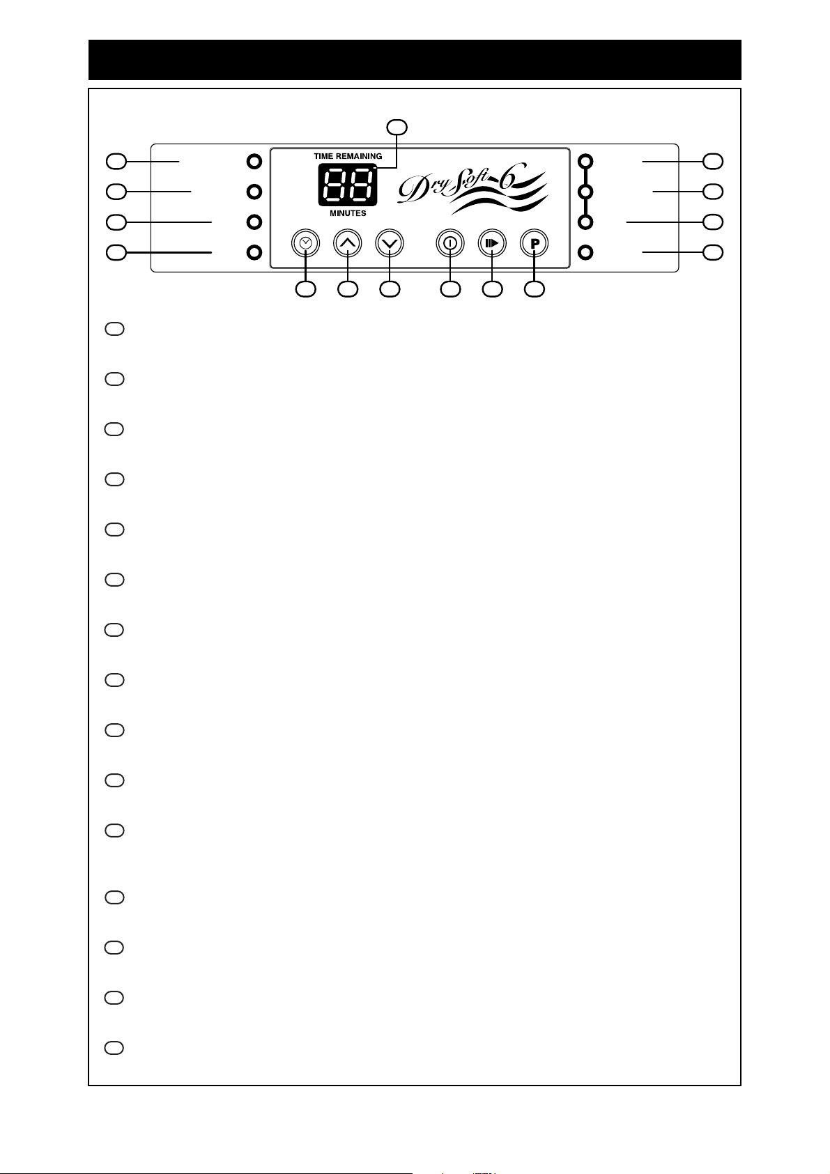
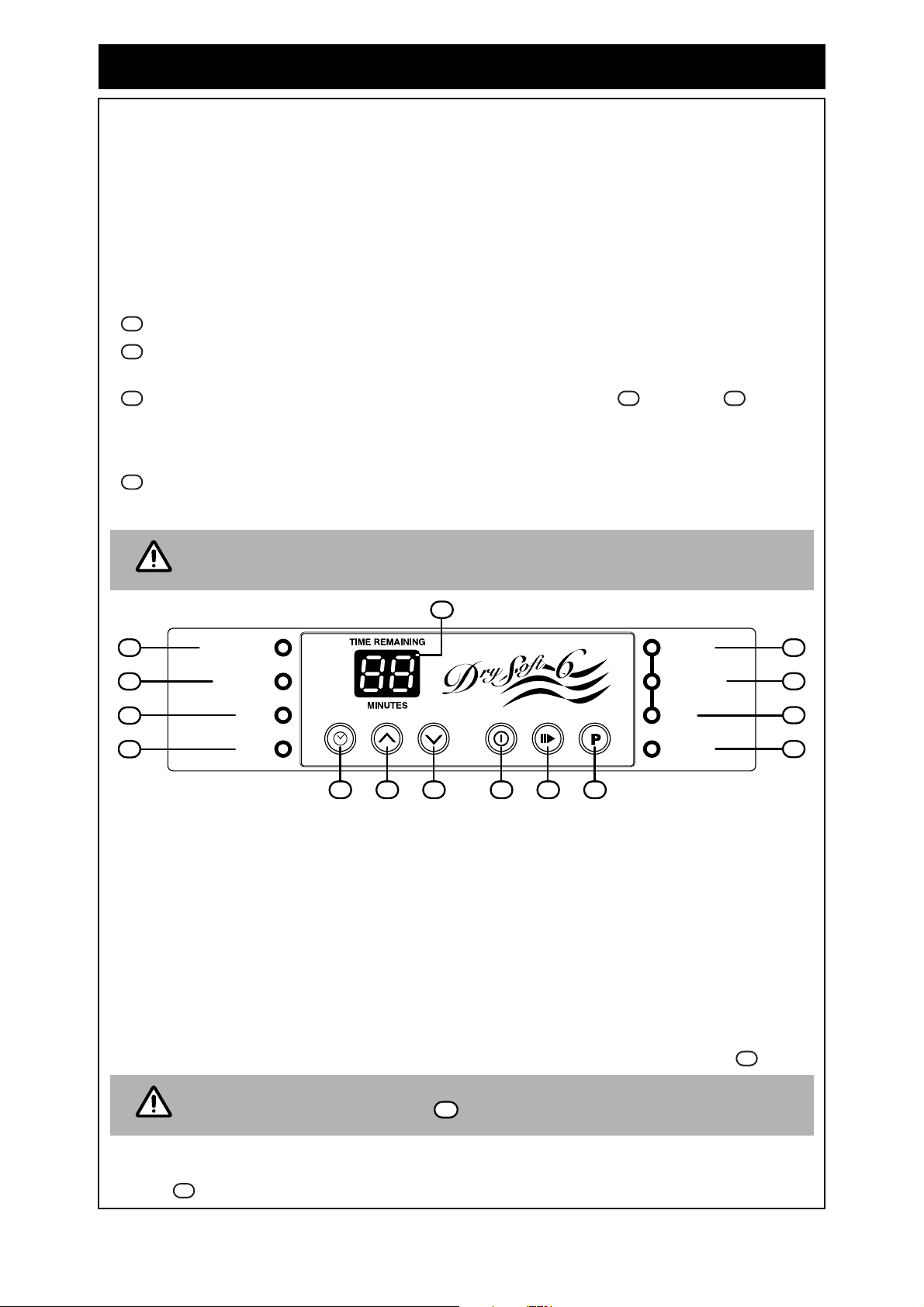
CONTROL PANEL NAVIGATION
15
14
11
12
13
ON / OFF BUTTON
1
CLEAN FILTER
OPERATING
FINISH
TIMER
5
Turn ‘ON’ and ‘OFF’ the electric power supply to the appliance.
START/PAUSE BUTTON
2
Start and pause the drying function.
PROGRAM BUTTON
3
Select the drying programme.
TIMER BUTTON
4
Select operation in Timer mode.
’UP’ BUTTON
5
Increase the drying time (operation in Timer mode only).
GENERAL
EXTRA SOFT
THICK
DELICATE
32164
7
9
8
10
‘DOWN’ BUTTON
6
Decrease the drying time (operation in Timer mode only).
GENERAL INDICATOR
7
Illuminates green when the ‘General’ drying mode has been selected.
THICK INDICATOR
8
Illuminates green when the ‘Thick’ drying mode has been selected.
EXTRA SOFT INDICATOR
9
Illuminates green when the ‘Extra Soft’ drying mode has been selected.
DELICATE INDICATOR
10
Illuminates green when the ‘Delicate’ drying mode has been selected.
OPERATION INDICATOR
11
Illuminates green when drying function has started but the gas burner is not ignited. Illuminates
red when the gas burner is ignited.
FINISH INDICATOR
12
Illuminates green when drying is completed.
TIMER INDICATOR
13
Illuminates green during operation in Timer mode.
CLEAN FILTER INDICATOR
14
Illuminates red when the filter requires cleaning.
DIGITAL DISPLAY
15
Indicates remaining drying time and error codes.
Rinnai 1 Dry-Soft® RD-400/600AU Operation Manual
Page 5
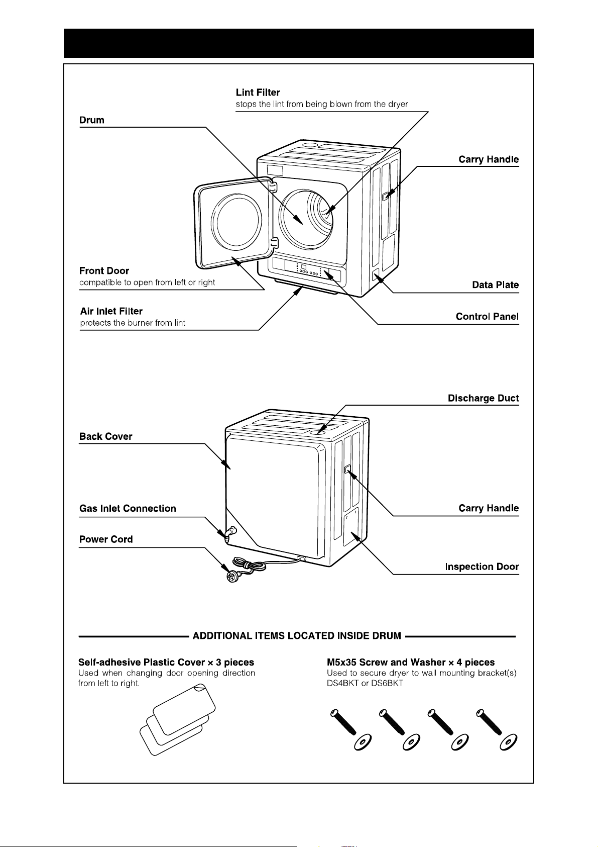
ABOUT YOUR DRY-SOFT GAS DRYER
OVERVIEW OF APPLIANCE
Rinnai 2 Dry-Soft® RD-400/600AU Operation Manual
Page 6
SAFETY INFORMATION
WARNING
DO NOT
DO NOT
DO NOT
DO NOT
DO NOT
OPERATE THIS APPLIANCE BEFORE READING THE
INSTRUCTION BOOKLET.
PLACE ARTICLES ON OR AGAINST THIS APPLIANCE.
STORE CHEMICALS OR FLAMMABLE MATERIALS,
OR SPRAY AEROSOLS NEAR THIS APPLIANCE.
OPERATE WITH PANELS, COVERS OR GUARDS
REMOVED FROM THIS APPLIANCE.
LOAD MATERIALS CONTAINING FLAMMABLE
SOLVENTS INTO THIS APPLIANCE
• Ensure all articles are removed from pockets. These include flammable items
such as matches and cigarette lighters.
• DO NOT dry clothes or materials containing foam, glue or other flammable
substances or materials.
• DO NOT use this appliance to dry off solvents, dry-cleaning fluids or other
flammable substances.
• DO NOT dry articles that have come into contact with cooking oils, petrol, dry
cleaning solvents or other flammable or explosive substances. These substances
may emit vapours or cause a chemical reaction resulting in fire or explosion.
• DO NOT operate the dryer whilst the CLEAN FILTER light is on. Any lint must be
regularly removed in accordance with these instructions.
• DO NOT open the dryer door whilst the dryer is in operation. The dryer door
should only be opened after the FINISH light illuminates.
• When the dryer cycle is finished, take care when removing laundry items. They
may still be warm or HOT.
• DO NOT use the gas clothes dryer for any purpose other than the drying of
clothes.
• Fresh air ventilation openings shall not be blocked and/or sealed.
• This appliance is not intended for use by young children or infirm persons with out
supervision. Young children should be supervised to ensure they do not play with
this appliance.
• DO NOT cover or place any articles on or against this appliance.
• DO NOT store chemicals or flammable materials or spray aerosols near this
appliance.
• DO NOT unplug the electric power cord whilst in operation.
• Ensure clothes DO NOT get stuck between the dryer door and drum. Appliance
and clothing damage may occur and an unsafe situation could result.
• DO NOT operate these appliances without the exhaust duct. These appliances
must be operated with the exhaust duct connected and terminated in accordance
with these instructions.
• If the supply cord is damaged, it must be replaced by the manufact ure r, its service
agent or similarly qualified person in order to avoid a hazard.
Rinnai 3 Dry-Soft® RD-400/600AU Operation Manual
Page 7
FEATURES AND BENEFITS
1. Quick Drying - The range of Rinnai gas clothes dryers utilise gas as the drying medium rather
than electricity. This results in a considerable reduction in drying time when compared to most
electric clothes dryers.
2.
Economical - The range of Rinnai gas clothes dryers are highly efficient. In addition, they utilise
gas rather than electricity as the drying medium. Depending on the gas type used considerable
running costs savings are possible when compared to electric clothes dryers.
Soft Clothes - Using gas as the drying medium result s in clothes tha t feel sof t er wh en compared
3.
to electric clothes dryers.
Automatic Operation - Dryer stops automatically when drying is completed. Th is eliminates the
4.
need by the user to guess how long drying might take.
5.
Time remaining indicator - Indicates the remaining time for completion of drying.
6.
Exhaust Duct - The exhaust duct vents to outside. This prevents the discharge of moist air, dust
and lint into the room containing the clothes dryer.
OPERATION
GENERAL INFORMATION
• Do not exceed the maximum drying load:
- The Maximum load for the Dry-Soft® 4 (Model RD-400AU) is 4 kg.
- The Maximum load for the Dry-Soft® 6 (Model RD-600AU) is 6 kg.
Exceeding the maximum drying load may result in uneven drying or appliance malfunction.
• Ensure clothes have been spin dried by a washing machine before placing into the gas clothes
dryer. Wet clothes may damage the dryer and will take excessively long to dry.
• Ensure washing detergents, bleaches and fabric softeners have been fully rinsed from clothes
before placing them into the gas clothes dryer. These substances may damage internal dryer
components.
• It is preferable that the space in which the gas clothes dryer is installed is well ventilated. This can
be achieved by opening a window during use.
FABRIC CARE AND DRYING HINTS
Read the fabric care label attached to most clothes to confirm if they are suitable for tumble drying
and, if so, select the drying cycle recommended by the manufacturer. In the ab sence of man ufacturer
recommendations Rinnai suggests the following:
• Use the 'GENERAL' cycle for items such as towels, shirts and underwear.
• Use the 'DELICATE' drying cycle for frayed or synthetic items (such as nylon stockings) or thin
fabrics. It is recommended that these items are placed in a laundry bag for protection during
drying.
• Use the 'THICK’ drying cycle for items such as jeans, sweatshirts or heavier winter clothes.
• If thick items are mixed with thin items, select the 'THICK' drying cycle.
• The volume of clothes in the dryer should be limited to approximately 70% of the actual drum
volume to maintain drying efficiency. If the volume of clothes exceeds 70% drying efficiency will
be reduced.
• Lint producing items (such as towels) should be dried separately to prevent the lint catching onto
other items during drying.
• For items with zippers, close the zippers and dry inside out to prevent damage to the dryer
components. The same applies to items with metallic buttons.
Rinnai 4 Dry-Soft® RD-400/600AU Operation Manual
Page 8
OPERATION
ITEMS UNSUITABLE FOR TUMBLE DRYING
• Do not tumble dry fabrics if the care label states that tumble drying is not suitable. These may
include items made from silk, wool, wool blends, leather, lace or hemp. These fabrics may shrink,
deform or fade. The same applies to items with printing or glued emblems which may fade or
separate.
• Non breathable fabrics, materials or items such as rain coats, leather, glued clothes, quilts, mats,
carpet, stuffed cushions and toys ar e unsuitable for tumble drying.
CHOICE OF OPERATING MODES AND CYCLES
Four operating modes are available as follows:
GENERAL: During the 'General' mode the gas dryer operates at full drying capacity.
7
THICK: During the 'Thick' mode the gas dryer operates for longer th an in the gen eral or delicate
8
modes.
EXTRA SOFT: This mode applies in conjunction with GENERAL or THICK modes.
9 7 8
When selected, the drying function stops intermittently. The drum sto ps rotating an d cool air is bl own
into the drying drum momentarily for 12 seconds every 4 minutes for a total cycle time of up to 120
minutes. This results in fabric that feels softer.
DELICATE: During the 'Delicate' mode the gas dryer operates at approximately half the drying
10
capacity.
i
NOTE
If the dryer door is opened during an operation cycle, the ‘Extra Soft’ function is
cancelled. There is no gas consumption during ‘Extra Soft’ operation.
15
14
11
12
13
CLEAN FILTER
OPERATING
FINISH
TIMER
5
32164
GENERAL
EXTRA SOFT
THICK
DELICATE
DRYING PROGRAMMES
Five drying programmes are available as follows:
GENERAL + EXTRA SOFT (Combines the GENERAL and EXTRA SOFT Programme modes)
GENERAL
THICK + EXTRA SOFT (Combines the THICK and EXTRA SOFT Program me mode s)
THICK
DELICATE
OPERATIONAL TIME
In automatic mode, the dryer senses the clothes volume, moisture content and drying progress
continuously. It will operate the drying function for the required amount of time for the clothes to be
dried sufficiently.The approximate remaining drying time is indicated on the digital display .
15
7
9
8
10
The remaining drying time indicated is approximate only and will be less accurate
NOTE
if the 'CLEAN FILTER' indicator is illuminated.
14
In timer mode, the user selects the duration for drying and the dryer will operate for the selected period
regardless of whether clothes are dry or not. The remaining drying time is indicated on the digital
display .
Rinnai 5 Dry-Soft® RD-400/600AU Operation Manual
15
Page 9

OPERATION
OPERATION IN AUTOMATIC MODE
1. Open the dryer door and place items selected for drying evenly into the dryer drum. Close the
dryer door and press the 'On/Off' button . The default drying programme is set to GENERAL
+ EXTRA SOFT and these mode indicators will be illuminated.
7 9
1
2. To select an alternative drying programme press the 'Programme' button until the desired
3
mode indicator illuminates. The drying programmes cycle through the following sequence:
GENERAL + EXTRA SOFT THICK+ EXTRA SOFTGENERAL THICK DELICATE
3. Press the 'Start / Pause' button . The 'OPERATING’ (Combustion) indicator will show
2
11
green, and will change to red after burner ignition which may take up to 10 seconds.
4. Drying will now commence. The approximate remaining drying time will be indicated on the digital
display . The 'OPERATING’ (Combustion) indicator may alternate between showing green
15 11
and red, however this is normal.
5. The dryer will stop when items are sufficiently dry. A tone will sound 3 times and the 'FINISH'
indicator will illuminate.
12
Before opening the dryer door, ensure the 'OPERATING’ (Combustion) indicator
shows green.
NOTE
11
If the dryer door is opened and closed dur ing op eration the dryer will go throug h a
cool down, purge and relight sequence that takes approximately 1 to 2 minut es.
OPERATION IN TIMER MODE
1. Open the dryer door and place items selected for drying evenly into the dryer drum. Close the
dryer door and press the 'On/Off' button .
2. Press the 'Timer' button , the ‘TIMER’ indicator illuminates and the default drying
programme is GENERAL and this mode indicator will be illuminated.
4
7
3. There are only two drying programmes available in “Timer’ mode, these are
GENERAL and DELICATE , press the 'Timer' button until the
7 10 4
desired programme mode indicator illuminates.
1
13
GENERAL
DELICATE
4. The default drying time in minutes is shown on the digital display . Change the drying time by
pressing the 'up' or 'down' buttons. The drying times that can be selected are
5 6
15
5,10,15,20,25,30,40,50,60,70* and 80* minutes (*Dry-Soft 6 model only).
The 'default' drying time is 20 minutes when the appliance is first c onnected t o the
NOTE
5. Press the 'Start / Pause' button , the ‘TIMER’ indicator will begin to flash to signify that a
‘Timer’ operation has begun. The 'Operating / Combustion' indicator will show green and will
electric power supply. If the appliance has operated in timer mode previously the
previous drying time selected will be shown as the default drying time.
2
13
9
change to red after burner ignition which may take up to 10 seconds.
6. Drying will now commence. The approximate remaining drying time will be indicated on the digital
display and will counted down in 5 minute increments. During operation the time may be
increased and decreased as desired by pressing the 'up' or 'down' buttons. The
'OPERA TING’ (Combustion) indicator will show green towards the end of the drying cycle, this
15
5 6
11
is normal.
7. The dryer will stop when the drying time has elapsed. A tone will sound 3 times, the ‘TIMER’
indicator will stop flashing and the 'FINISH' indicator will be illuminated.
13 12
Before opening the dryer door, ensure the 'OPERATING’ (Combustion) indicator
shows green.
NOTE
11
If the dryer door is opened and closed dur ing op eration the dryer will go throug h a
cool down, purge and relight sequence that takes approximately 1 to 2 minut es.
Rinnai 6 Dry-Soft® RD-400/600AU Operation Manual
Page 10

CARE AND MAINTENANCE
T
CLEANING THE LINT FILTER
The lint filter should be cleaned after every drying
cycle. Regular cleaning is important to maintain drying
efficiency.
The 'CLEAN FILTER' indicator illuminates when
the lint filter is too blocked and requires cleaning.
A alarm will also sound after operation stops for 5
minutes or until the dryer door is opened, whichever
comes first.
If the lint filter is not cleaned, the appliance will
eventually stop operating and an 'error' code will show
on the digital display . Refer to the Trouble
15
Shooting section on page 10 for details.
Clean the lint filter as follows:
Reach inside the drum of the dryer and remove th e
1
lint pocket/filter from the dryer by pulling on the four
finger slots of the lint pocket/filter.
Separate the lint filter from the lint pocket by pulling
2
apart as shown.
14
Remove any lint from the lint filter by using your
3
hands, a soft cloth or a soft brush as shown. If
removal of the lint proves difficult, the lint filter may
also be cleaned with the assistance of COLD water
and a soft cloth or brush.
If water is used to clean th e lint filter, then
CAUTION
4
it MUST BE thoroughly dried before it can
be re-installed.
Place the lint filter back into the lint pocket, before
attempting to push lint pocket and lint filter back
together ensure that the slotted ring of the lint filter
is forward most.
CLEANING THE BACK FILTER
The back filter is located inside the drum behind
5
the lint pocket/filter. It should be cleaned after every
drying cycle. It can usually be cleaned without
removal by using a soft cloth or brush.
Ensure dust removed from the back filter
IMPORTAN
does not remain in the drum.
If removal is required for cleaning, loosen the two
6
white plastic screws by hand or with the aid of a
phillip’s screw driver.
When re-inserting the back filter, align the holes in
7
the back filter to those in the back of the drum as
shown, insert the two white plastic screws and
hand tighten.
Rinnai 7 Dry-Soft® RD-400/600AU Operation Manual
Page 11

CARE AND MAINTENANCE
CLEANING THE AIR INLET FILTER
The air inlet filter is located at the bottom of the
8
appliance. Pull it out as shown.
Remove any dust from the air filter by using your
9
hands, a soft cloth or a soft brush as shown.
If removal of the lint proves difficult, the air filter
may also be cleaned with the assistance of COLD
water and a soft cloth or brush.
After removing dust, re-insert the air inlet filter . The
10
sides of the filter are located and guided by rails at
the bottom of the dryer body.
If water is used to clean the air filter, then it
CAUTION
MUST BE thoroughly dried before it can be
re-installed.
CLEANING THE HEATER BODY
Unplug the electrical cord before cleaning. All external parts of the appliance can be cleaned using a
soft, damp cloth and mild detergent.
DO NOT USE SOLVENTS FOR CLEANING THIS APPLIANCE.
DO NOT
SAFETY DEVICES
For your safety and peace of mind the Dry-Soft® range of gas clothes dryers are fitted with following
safety devices:
Flame failure sensing
Appliances shuts down in case of flame failure.
Drying drum overheat switch
Appliance shuts down in case the drying drum overheats. Self resetting.
Electric motor overheat switch
Appliance shuts down in case the motor overheats. Self resetting.
Drum Belt safety switch
Appliance shuts down in case of drum belt breakage.
Door Switch
Appliance cannot start unless appliance door is properly closed.
Blocked filter warning
Filter indicator lights up in case of blocked filter(s).
Electric Fuses
Protects appliance in case of electrical overload.
Rinnai 8 Dry-Soft® RD-400/600AU Operation Manual
Page 12

TROUBLE SHOOTING
TROUBLE SHOOTING CHECK LIST
Please check the following list before calling for Service. Service calls may be charged if faults are
caused by operation errors. Refer to the Warranty Conditions for more details.
If the dryer does not operate at all, check to see if the digital display is flashing with two numbers. If
yes, refer to “ERROR CODES” on page 10. If no, check the following items:
• Is the gas supply turned on?
• Is the electrical plug connected to the power supply and is the power supply switched on?
• Is electrical power available? Check supply fuses are serviceable.
• Have the 'On/Off' and 'Start Pause' buttons been presse d in accordance with these instructions?
• Is the dryer door properly closed?
• Is the digital display flashing with two numbers?
If the dryer takes too long to dry or clothing is not drying well, check the following items:
• Is the ‘CLEAN FILTER' indic ator illuminated? If yes, clean the filters in accordance with the
‘CARE AND MAINTENANCE’ instructions on page 7.
• Ensure garments have been through the washing machine spin cycle before loading into the
appliance for drying.
• Ensure garments for drying are not added during operation.
• Ensure the 'THICK' drying programme has been selected if thick garments are being dried.
GENERAL DRYER CHARACTERISTICS
The following symptoms are part of the normal opera tio n of the applian ce and do not indicate a fault:
SYMPTOMS REASON
The drum is turning even after the finishing tone
has sounded.
There is a delay after pressing the 'Start/Pause'
switch before the Operating indicator shows
red.
2
14
Dryer is operating under the 'Extra Soft'
programme.
Opening the dryer door will cancel the 'Extra
Soft' programme.
It may take some time before the burner ignites
and combustion starts.
This is a normal operational characteristic,
however if the burner does not ignite at all,
contact Rinnai.
Steam is emitted from the discharge duct
terminal.
There are some clicking noises afte r dry ing fir st
starts and after the drying cycle has finished.
The 'time remaining' shown in the digital display
has not changed for a number of minutes.
Rinnai 9 Dry-Soft® RD-400/600AU Operation Manual
High efficiency appliances tend to discharge
steam, especially on cold days. This is normal.
This is due to the expansion and contraction of
burner components with heat and is a normal
operational characteristic.
During operation in Automatic mode, the control
system continually calculates the remaining
drying time based on the rate of drying of
garments. This is a normal operational
characteristic.
Page 13

TROUBLE SHOOTING
ERROR CODES
Rinnai Dry-Soft gas clothes dryers have a self diagnostic function. If a fault occurs, a 2 digit code will
flash on the Digital Display on the control panel. This assists with diagnosing the fault and may
enable a problem to be solved without the need for attendance by service personnel. Please quote
the code displayed when arranging a service call.
Code(s) Displayed Possible Cause Remedy
05, 32, 90 Filter Blockage(s) Check and clean lint filter, back filter and air inlet filter.
11 Ignition Failure
15
Check the gas supply is turned 'on'.
Turn appliance 'off' then 'on' again.
Arrange for service if the above does not remedy the
fault.
Check the gas supply is turned on fully.
12 Flame Failure
Other - Arrange for service.
SERVICE
Rinnai recommend that this appliance be serviced every 2 years.
Any service or repair work should only be carried out by an authorised person. Rinnai Australia has a
service and spare part network in all States. Rinnai service personnel are fully trained and equipped
to provide the best service for Rinnai appliances. If your appliance needs servicing, ring the Helpline
contact numbers on the back of this manual.
Service calls for general cleaning, maintenance and wear and tear are not
NOTE
necessarily covered under the warranty. Service calls of this nature may be
chargeable.
If the power supply cord or any other component of the dryer are damaged, they
must be replaced by Rinnai or an Authorised person.
Service and repair work must be carried out by an Authorised person.
Check and clean lint filter, back filter and air inlet filter
Arrange for service if the above does not remedy the
fault.
Rinnai 10 Dry-Soft® RD-400/600AU Operation Manual
Page 14

INSTALLATION MANUAL
SPECIFICATIONS ...................................................................................................12
POSITIONING OF THE APPLIANCE ......................................................................13
GAS CONNECTION AND SUPPLY .........................................................................13
ELECTRICAL SUPPLY ............................................................................................14
APPLIANCE MOUNTING OPTIONS ........................................................................14
FLOOR MOUNTING.................. ... ... .......................................... .... ... ... ...................................... 14
BENCH OR SHELF MOUNTING............................................................................................... 14
WALL MOUNTING .................................................................................................................... 14
WALL MOUNTING BRACKET ASSEMBLY.............................................................................. 15
WALL MOUNTING BRACKET AND DRYER INSTALLATION.................................................. 15
SWAPPING DOOR FROM LEFT TO RIGHT OPENING ..........................................16
EXHAUST DUCT ......................................................................................................17
HORIZONTAL AND VERTICAL TERMINAL CLEARANCES.................................................... 17
VENTILATION REQUIREMENTS ............................................................................................. 17
EXHAUST DUCT SYSTEM COMPONENTS: ........................................................................... 18
ATTACHING THE APPLIANCE ADAPTER SPIGOT................................................................ 18
ATTACHING EXHAUST DUCT LENGTHS............................................................................... 18
ATTACHING EXHAUST DUCT VERTICAL ROOF TERMINAL................................................ 18
ATTACHING EXHAUST DUCT HORIZONTAL WALL TERMINAL........................................... 18
EXHAUST DUCT INSTALLATION OPTIONS........................................................................... 19
Rinnai 11 Dry-Soft® RD-400AU / RD-600AU Installation Manual
Page 15

INSTALLATION
SPECIFICATIONS
Description: Rinnai Gas Dryer - Dry-Soft® 4 Rinnai Gas Dryer - Dry-Soft® 6
Model: RD-400AU RD-600AU
Dimensions (mm) Height: 609, Width: 550, Depth: 490 Height: 684, Width: 650, Depth: 530
Gas Consumption 13 MJ/h 16.5 MJ/h
Gas Supply Pressure (kPa)
Weight: (Body only) 27.0 kg 32.4 kg
Standard Drying Capacity 4 kg per time 6 kg per time
Standard Drying Time 60 minutes 60 minutes
Gas Connection ½" female flared fitting ½" female flared fitting
Power Supply 240V (50 Hz) 240V (50 Hz)
Electric Consumption 260 Watts 280 Watts
Power Cord Length 1.5 metres 1.5 metres
Natural Propane Natural Propane
1.13 / 2.75 2.75 1.13 / 2.75 2.75
Drying drum overheat switch
Electric motor overheat switch
Safety Devices
Drum Belt safety switch
All dimensions in this manual are in millimetres (mm) unless otherwise stated.
NOTE
Appliance Dimensions RD-400AU
Flame failure sensing
Door Switch
Blocked filter warning
Electric Fuses
Flame failure sensing
Drying drum overheat switch
Electric motor overheat switch
Drum Belt safety switch
Door Switch
Blocked filter warning
Electric Fuses
Appliance Dimensions RD-600AU
Rinnai 12 Dry-Soft® RD-400AU / RD-600AU Installation Manual
Page 16

INSTALLATION
T
This appliance shall be installed in accordance with:
IMPORTANT
POSITIONING OF THE APPLIANCE
The main considerations when positioning the dryer are:
• Ensuring all minimum clearance requirements as shown are met.
• The location / termination of the exhaust duct system and terminal (To comply with AS 5601).
• Allowing sufficient access for ease of operation, servicing and removal of the appliance.
• Ensuring there is access to the exhaust duct connection, gas connection and air inlet filter to th e
• Ensuring there is enough ‘flex’ in the flexible gas hose when the appliance is in the installed
• Ensuring a 20mm(¤) minimum clearance be tween the exha ust duct and any comb ustible materi als.
• Ensuring that a 100mm(*) gap is provided for the opening swing of the dryer door. The dryer door
• The access door of an enclosed installation(#) must be vented with a minimum open area of
45
• Manufacturers’ Installation Instructions
• Local gas fitting regulations
• Municipal building codes
• AS 5601 Gas Installations and AS/NZS 3000 Wiring Rules
• Any other relevant Statutory Regulations
This appliance must be installed, serviced and removed by an Authorised Person.
appliance in the installed position.
position to allow for vibration which may occur during operation.
can be hinged from the left or right hand sides and therefore a gap must be provided appropriately.
250cm² (See item on page 17). A Rinnai ‘VENT’ is suitable for this purpose.
d G
55
238
20 ¤
120
120
20 ¤
150
100 *
45
TOP VIEW SIDE VIEW
440
SIDE VIEW
Enclosed Installation #
440 plus a reasonable
amount for access ~500
45
Gas connection
access hole Ø30
Chemicals or flammable materials must not be stored near the
appliance or the exhaust duct. This applies especially if the dryer is
CAUTION
positioned onto shelves or inside a cupboard.
GAS CONNECTION AND SUPPLY
The position of the gas connection is show n in “Appliance Dimensions RD-40 0AU / RD-600AU” on
page 12. The appliance is supplied with a 300mm braided flexible gas hose with a ½" female flared
fitting for connection to the consumer piping. For gas supply pressures refer to “SPECIFICATIONS”
on page 12.
The connection between the gas supply consumer piping and the flexible 300mm gas
IMPORTAN
hose flared connection must be accessible for disconnection and reconn ection when
the appliance is in the final installed position.
There must be enough 'flex' in the flexible gas hose when the dryer is installed to
allow for any vibration of the dryer that may occur during operation.
Gas pipe sizing must consider the gas input to this appliance as well as all other gas
appliances in the premises. The gas meter and regulator must be specified for the
total gas rate. Suitable sizing chart such as the one in AS 5601 should be used.
All foreign materials such as swarf must be purged from the gas supply, as they ma y
cause the gas control valve to malfunction .
Rinnai 13 Dry-Soft® RD-400AU / RD-600AU Installation Manual
Page 17

INSTALLATION
T
ELECTRICAL SUPPLY
This appliance is supplied with a 1.5 metre long power co rd with a three pin plug. Rinnai re commends
that the dryer be plugged into a dedicated 240V, 10A earthed power point.
Alternatively the appliance can be direct wired if the power supply is to be concealed.
Consult a qualified electrician if direct wiring is required as it must comp ly with the
IMPORTAN
APPLIANCE MOUNTING OPTIONS
Rinnai gas dryers may be floor, bench, shelf or wall mounted.
requirements of AS 5601, AS 3000 and any other relevant local regulations.
Floor Mounting Bench Mounting
Shelf / Cupboard
Mounting
Wall Mounting
FLOOR MOUNTING
There are no specific requirements for floor mounting of the appliance other than those that are listed
under “POSITIONING OF THE APPLIANCE” on page 13.
BENCH OR SHELF MOUNTING
Position the appliance in accordance with the requirements that are listed under “POSITIONING OF
THE APPLIANCE” on page 13.
When bench or shelf mounted, the appliance is supported by the four rubberised ‘feet’ at the base of
the appliance. These do not need to be fastened or secured to the bench or shelf. The following items
must be considered:
• The bench or shelf and it’s suppo rt(s) should be of suf f icient strength and constr uction to support the
weight of a fully loaded dryer plus the weight of any other goods it is intended to support. The loaded
weight allowances are Dry-Soft 4, 35kg and Dry-Soft 6, 45kg.
• Stability of the appliance. The bench or shelf dimension must have at least the same width and
depth as that of the appliance to provide sufficient area to support the four rubberised ‘feet’ at the
base of the appliance and allow for slight movement that may occur during operation.
WALL MOUNTING
Position the appliance in accordance with the requirements that are listed under “POSITIONING OF
THE APPLIANCE” on page 13
If the dryer is to be wall mounted, the following must be considered:
• Only the Rinnai wall mounting bracket must be used (Order codes: DS4BKT for Dry-Soft 4 and
DS6BKT for Dry-Soft 6). Alternative brackets or wall mounting options are unsuitable.
• The wall and method for fastening the wall mounting bracket to the wall must be of sufficient
strength and construction to support the weight of a fully loaded dryer. The loaded weight
allowances are Dry-Soft 4, 35kg and Dry-Soft 6, 45kg.
• The four rubberised ‘feet’ at the base of the appliance must be securely fastened to the base of the
mounting bracket using the 4 mounting screws supplied (See “WALL MOUNTING BRACKET AND
DRYER INSTALLATION” on page 15).
Rinnai 14 Dry-Soft® RD-400AU / RD-600AU Installation Manual
Page 18

INSTALLATION
WALL MOUNTING BRACKET ASSEMBLY
The wall mounting bracket is provided in kit form with the following components:
1 x Wall Fame
1 x Support Frame
4 x Hex Head Bolts and Washers
4 x Mounting Screws and Washers
Some minor assembly is required before the wall mounting bracket can be fixed to the wall.
To assemble the wall mounting bracket use the four hex head bolts and washers provided and
securely attach the support frame to the wall frame.
WALL MOUNTING BRACKET AND DRYER INSTALLATION
Attache the wall mounting bracket to a suitable wall with appropriate fixings.
Lift the dryer onto the installed wall mounting bracket taking care to locate the four securing holes of
the support frame with the four inner most holes of the appliances moulded feet.
Secure the Dryer to the frame with the four mounting screws and washers provided.
4 x Moulded Feet
4 x Moulded Feet
4 x Securing Holes
4 x Securing Holes
4 x Mounting Screws andWashers
4 x Mounting Screws andWashers
Rinnai 15 Dry-Soft® RD-400AU / RD-600AU Installation Manual
Page 19

INSTALLATION
SWAPPING DOOR FROM LEFT TO RIGHT OPENING
The dryer access door may be swapped from a left handed opening as supplied from the factory to a
right handed opening. When changing door opening direction ensure the appropriate clearances are
provided. Refer to “POSITIONING OF THE APPLIANCE” on page 13 for clearance details.
Open the dryer door fully so that it
1
locks in the open position.
Remove the two plastic tabs from
2
the appliance body to reveal the
right hand door hinge attachment
points.
Unscrew and remove the door latch
3
from the left handed position.
Apply one of the three self-adhesive
4
plastic tabs (supplied with the
appliance) over the left handed door
latch attachment point.
With the door still locked in the open
5
position remove the retaining screws
for each of the upper and lower
hinges. Remove the door with the
hinges attached by using an upward
motion to disengage the ‘T’ shaped
slots of the left handed hinge
attachment points.
After removing the door the
from the appliance the upper
NOTE
hinge will be locked into
position. However care must
be taken as the lower hinge is
only held in place by gravity.
1
4
5
180°
2
3
2
9
6
Rotate the door by 180°, ensuring
6
that the lower hinge is held in place
8
and re-attach the door to the right
hand attachment points by engaging
7
the ‘T’ shaped slots with a downward
motion. Secure both the upper and
10
11
lower hinges with a retaining screw.
Remove the plastic tab from the
7
appliance body to reveal the right
hand door latch attachment point.
Attach the door latch removed in
8
step to the above attachment
3
10
point.
180°
25mm pin
11
11
Using the remaining two self-
9
adhesive plastic tabs cover up the
left hand door hinge attachment
10
25mm pin
10
points.
Remove both the door window retaining bracket that has the 25mm pin and the door win dow
10
retaining bracket that is diagonally opposite.
Reverse the above brackets by 180° and re-attach them to the door so that the pinned bracket
11
is now in the upper most position.
9
11
Rinnai 16 Dry-Soft® RD-400AU / RD-600AU Installation Manual
Page 20

INSTALLATION
T
EXHAUST DUCT
Rinnai gas dryers must be installed with Rinnai gas dryer exhaust duct components. Two exhaust duct
kits are available, DFVKIT - vertical exhaust kit and DSHKIT horizontal exhaust duct kit. Each kit
consists of rigid aluminium pipes (can be cut to length as required) and vertical or hori zontal terminals,
stand-off brackets, rigid bends and an internal wall plate. Additional pipes and bends are available
separately if the contents of the basic kits do not meet the installations requirements.
Exhaust products from gas dryers must not be discharged into exis ting 'natural draft'
IMPORTAN
HORIZONTAL AND VERTICAL TERMINAL CLEARANCES
flue systems associated with other gas appliances. The exhaust duct(s) from multiple
Rinnai gas dryers must not be combined into a common discharge and must not be
combined with flue or exhaust duct systems from other appliances. The gas dryer is
classified as a 'fan assisted flue appliance' in AS 5601 'Gas Installations'. It must be
located so that the exhaust duct terminal exits the build ing at a suitab le point. If the
horizontal (wall) terminal is used, the location must be in accordance with Section 5
and Figure 5.3 of AS 5601. If a vertical (roof) terminal is used, the location must be in
accordance with Section 5 of AS 5601.
VENTILATION REQUIREMENTS
d
d
For enclosed installations ONLY, a minimum
d
Rinnai 17 Dry-Soft® RD-400AU / RD-600AU Installation Manual
2
250 cm
of Free Air Ventilation is required.
Page 21

INSTALLATION
g
A
A
EXHAUST DUCT SYSTEM COMPONENTS:
A
DSFSPIGOT
Appliance adapter spigot (supplied with applianc e) .
B
DSFPIPE1000
Duct pipe 1000mm and stand-off clip
(installed length 950mm, can be cut to length as required ).
C
DSVCOWL
Vertical roof terminal 1060mm and stand-off clip
(installed length to exhaust outlet 900mm).
D
DSFBEND
Pair of 45° elbows.
E
DSFPLATE
Internal wall plate.
F
DSHCOWL
Horizontal wall terminal.
G
VENT
Air vent, provides an open area of 250 cm² (x 2).
DSVKIT, Vertical Exhaust Duct Kit DSHKIT, Horizontal Exhaust Duct Kit
B C B D
DSFPIPE1000 x 2 DSVCOWL x 1 DSFPIPE1000 x 1 DSFBEND x 1
E E F
DSFPLATE x 1 DSFPLATE x 1 DSHCOWL x 1
ATTACHING THE APPLIANCE ADAPTER SPIGOT
Locate and remove the two mounting screws from either sid e of
the discharge duct, top left rear corner of the dryer.
Retrieve the appliance adapter spigot DSFSPIGOT , which is
shipped inside the drum of the dryer.
Attach the DSFSPIGOT to the discharge duct using the two
A
mounting screws removed earlier, so that the flange of the
spigot is seated flush with the top panel of the dryer.
ATTACHING EXHAUST DUCT LENGTHS
The exhaust duct components DSFPIPE1000 , and
DSFBEND , may be connected directly to the appliance
adapter spigot .
D
A
B
With the female socket end facing down, slide the selected
exhaust duct component over the DSFSPIGOT until the
female socket fully engages the spigot by 50mm.
Fit further exhaust duct components as required, maintaining
the ‘female socket end down’ orientation for the entire duct run
to the termination. Ensure that each female so cket fully engages
the male ends by 50mm.
ATTACHING EXHAUST DUCT VERTICAL ROOF TERMINAL
The DSVCOWL is fitted directly to either a DSFPIPE1000
or DSFBEND . Ensure that the female socket fully engages
C B
D
the male end by 50mm.
ATTACHING EXHAUST DUCT HORIZONTAL WALL TERMINAL
The DSHCOWL is fitted flush to the wall surface over a
35mm external wall penetration of a DSFPIPE1000 .
Secure the DSHCOWL using the 3 fixing holes provided in
F
B
F
the wall flange.
Rinnai 18 Dry-Soft® RD-400AU / RD-600AU Installation Manual
Page 22

INSTALLATION
EXHAUST DUCT INSTALLATION OPTIONS
Following are the four most common exhaust duct installation methods. The exhaust duct length can
be up to 8 metres long with a maximum of two 90° bends:
i ii iii
iv
a
C C C
c
b
e
e
B
e
b
D
e e
D
D
D
B
e
D
B
D
e
E
E
B
D
D
B
f
A
b
d
G
Direct Vertical.
i
Offset Vertical.
ii
Extended Vertical.
iii
iv
Direct or Extended Horizontal.
a
Minimum clearance 500mm to nearest part of roof.
Minimum clearance 20mm to combustible materials.
b
c
Decktite or other non lead based flashing, to be provided by installer.
d
For enclosed installations ONLY, a minimum 250cm2 of Free Air Ventilation is required.
e
The weight of the exhaust duct MUST BE supported by the stand-off supplied and NOT by the dryer.
f
A constant 2° fall to t he terminal MUST BE maintained on horizontal installations.
g
‘DSFPIPE1000’ can be cut to length as is required, provided that a clean square edge is maintained and that a minimum
penetration of 50mm remains to join other exhaust duct components.
B
B
F
g
Rinnai 19 Dry-Soft® RD-400AU / RD-600AU Installation Manual
Page 23

APPLIANCE DETAILS
For future reference please take a moment to complete the following information:
Your Retailer:
Name:
Installation Address:
Telephone No.
Date of Purchase:
Gas Dryer Model:
______________________________________________
______________________________________________
______________________________________________
______________________________________________
________ / ________ / _______________________
RD - ________________ AU
Serial Number:
______________________________________________
Rinnai 20 Dry-Soft® RD-400AU / RD-600AU Installation Manual
Page 24

CONTACT INFORMATION
Australia Pty. Ltd.
ABN 74 005 138 769
Head Office
10-11 Walker Street,
Braeside, Victoria 3195
P.O. Box 460
Tel: (03) 9271 6625
Fax: (03) 9271 6622
Rinnai has a Service and Spare Parts network with personnel who are fully trained
and equipped to give the best service on your Rinnai appliance. If your appliance
requires a service, please call our National Help Service Line. Rinnai recommends
that this appliance be serviced every 2 years.
21 Dry-Soft® RD-400/600AU TSD 05-012 Issue 1- 3/11/06
Internet: www.rinnai.com.au E-mail: enquiry@rinnai.com.au
National Help Lines
Sales & Service
Tel: 1300 555 545* Fax: 1300 555 655*
Spare Parts & Technical Info
Tel: 1300 366 388* Fax: 1300 300 141*
*Cost of a local call Higher from mobile or public phones.
BARCODE
123 45678 90123 4
U-PART Nº.
Printed in Japan YYYY.MM
 Loading...