


RT-9000B
SECTION 7.3
OPERATION
7.3.1 GENERAL
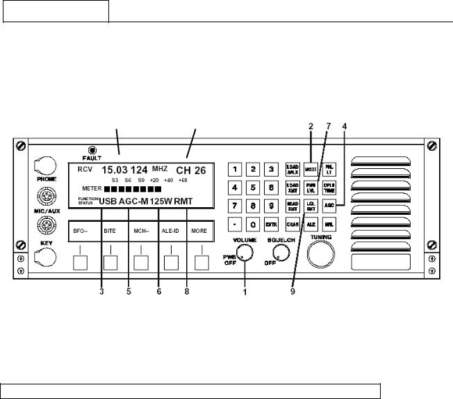
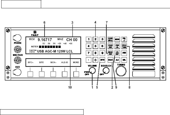
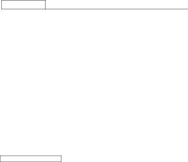
This section provides the operator with the location and use of the RT-9000B front panel controls for proper utilization of the equipment. For convenience of discussion, functions are addressed in normal sequence. However, it is not necessary to observe this order once the user becomes familiar with the equipment. Any setting may be changed independently by referring to the appropriate section in this chapter pertaining to the function in question. Reference to Figure 7.3.1.1 below, shows the location of the control groups, displays, and their general purpose.
RT-9000 B
Figure 7.3.1.1 RT-9000B Front Panel Controls
1 ON/OFF VOLUME CONTROL
When this control is in the full counter clockwise position, the equipment is OFF. To power-up the unit, rotate the control clock-wise. Once on, the internal speaker audio output level is initially at minimum. Rotating the volume control clock-wise increases the speaker audio output level.
NOTE: The setting of this control does not affect the level of the Remote Audio
Line outputs from the equipment rear panel.
Document No. 8128000560 |
7-9 |
Software Revision – N1B (07 Oct 04) |
|

RT-9000B
2 FAULT INDICATOR
This Red indicator is lit if a ‘FAULT’ condition is detected in the RT-9000B Transceiver. Check the installation and proceed to the section on BITE (Built-In-Test-Equipment), located in section 7.3.3.1 of this manual.
3 OPERATIONAL DISPLAY
This Liquid Crystal Display (LCD), provides a variety of information required to operate the equipment. Information is displayed in four primary areas of the display as indicated in Figure 7.3.1.2.
Frequency Information |
|
Channel |
|
Information |
|
|
|
|
Meter Information |
|
|
|
||
Function & Status Information |
||
|
|
|
FIG 7.3.1.2 RT-9000B Operational Display - Information Location
4 FUNCTION KEYS
This group of twelve (12) keys is used to control the primary operating functions of the RT-9000B Transceiver such as Mode selection, Channel selection, Channel loading, AGC characteristic selection, Local/Remote operation, Power Output level selection, Panel Illumination, Coupler Tune command, and manual tuning.
5 MANUAL TUNING CONTROL
This control is used to control manual tuning of the RT-9000B Transceiver frequency or channel selection. Actual frequency setting or channel selection is indicated in the Operational Display.
6 FREQUENCY/CHANNEL ENTRY KEYS
This group of twelve (12) numeric keys is primarily used for frequency information entry. This keypad may be used to enter, select, or load a specific operating frequency or Channel Number. This keypad may also be used to enter other numerical settings and parameters.
7-10 |
Document No. 8128000560 |
|
Software Revision – N1B (07 Oct 04) |

RT-9000B
7 SQUELCH CONTROL
This control is used to set the silencing threshold for the squelch circuit. When this control is set to the full counter-clockwise position, the squelch circuit is disabled and the equipment is unsquelched (fully unsilenced).
Rotating the control clock-wise enables the squelch circuit and sets its silencing threshold. When the control is initially moved, a click will be felt indicting the Squelch switch has been actuated. Clock-wise control rotation is continued until the RT-9000B’s Receiver noise just silences (or is “Squelched”).
When set as described above, the squelch circuit is active but maximum Receiver sensitivity has been maintained. Further clock-wise Squelch control rotation increases the signal strength required to “open” the squelch and allow an incoming signal to be heard. This action also effectively decreases Receiver sensitivity.
8 FEATURE KEY MENU DISPLAY
This display provides names of functions or selections for the five (5) keys located directly below the display. In most cases, this display automatically indicates the appropriate selections based upon the condition of other equipment settings. The menu may be changed by depressing the fifth key under ‘MORE’.
9 FEATURE KEYS
This group of five (5) “Soft” keys enables various functions as indicated in the display located directly above these keys.
NOTE: An asterisk (*) appearing at the right-hand side of a function in the display indicates that the feature preceding it is enabled, selected, or ‘ON’.
The RT-9000B Transceiver controls can be divided into three categories:
A.Primary Operations (Section 7.3.2)
B.Equipment Set-Up (Section 7.3.3)
C.Advanced Operations (Section 7.3.4)
Document No. 8128000560 |
7-11 |
Software Revision – N1B (07 Oct 04) |
|
RT-9000B
7.3.2 PRIMARY OPERATIONS
The RT-9000B operations described in this manual section cover the most basic and common operations.
|
|
10 |
|
|
11 |
|
|
|
|
|
|
|
|
|
|
|
|
|
|
|
|
|
|
|
|
|
|
|
|
|
|
|
|
|
RT-9000 B
Figure 7.3.2.1 RT-9000B Basic Set Up Controls
7.3.2.1 TRANSCEIVER MODE, AGC, AND TRANSMIT POWER SET UP
These settings determine the basic operating characteristics for the Receiver and Transmitter sections of the RT-9000B Transceiver. These settings are Transceiver Emission Mode, Receiver AGC speed characteristic, and Transmitter RF Power Output level.
Unless otherwise noted, refer to Figure 7.3.2.1 for the location of controls and features.
Transceiver Emission Mode Selection
To select the Emission Mode, depress ‘MODE’ key successively at 2 until the desired selection appears in Operational Display segment at 3. This selection applies to both Receive and Transmit operation. The choices are ‘USB’, ‘LSB’, ‘CW’, and ‘AM’. If the Data filter option has been installed in the RT-9000B Transceiver, a 'DATA' choice will also be displayed and be available.
Receiver AGC Speed Characteristic
To select the Receiver AGC speed characteristic, depress ‘AGC’ key successively at 4 until the desired selection appears in the Operational Display segment at 5. The choices are ‘AGC-S’ (Slow), ‘AGC- M’(Medium), and ‘AGC- F’(Fast). The ‘Slow’ AGC characteristic is generally desirable with speech transmission. The Fast AGC characteristic is desirable for data transmission.
7-12 |
Document No. 8128000560 |
|
Software Revision – N1B (07 Oct 04) |
RT-9000B
Transmitter Power Output Selection
Transmitter RF power output is indicated in the Operational Display segment at 7. Normally, this setting will be set to the ‘125W’ (Watts) power output level by default. If the ‘65W’ (Watts) RF power output level is desired, depress the ‘PWR LVL’ (Power Level) Key at 7. The indicated power level output will change accordingly.
NOTE: An external Linear Power Amplifier is frequently used with the RT-9000B Transceiver. The system will automatically detect when this optional equipment is present and automatically adjust the available Power Output Level choices. Depending on the specific amplifier model, the additional Power Output Level choices will be ‘500W (500 Watts) or ‘1000W’ (1000 Watts).
THE BASIC OPERATING SETTINGS OF THE REMOTE TRANSCEIVER HAVE NOW BEEN ESTABLISHED.
7.3.2.2 ESTABLISHING AN OPERATING FREQUENCY
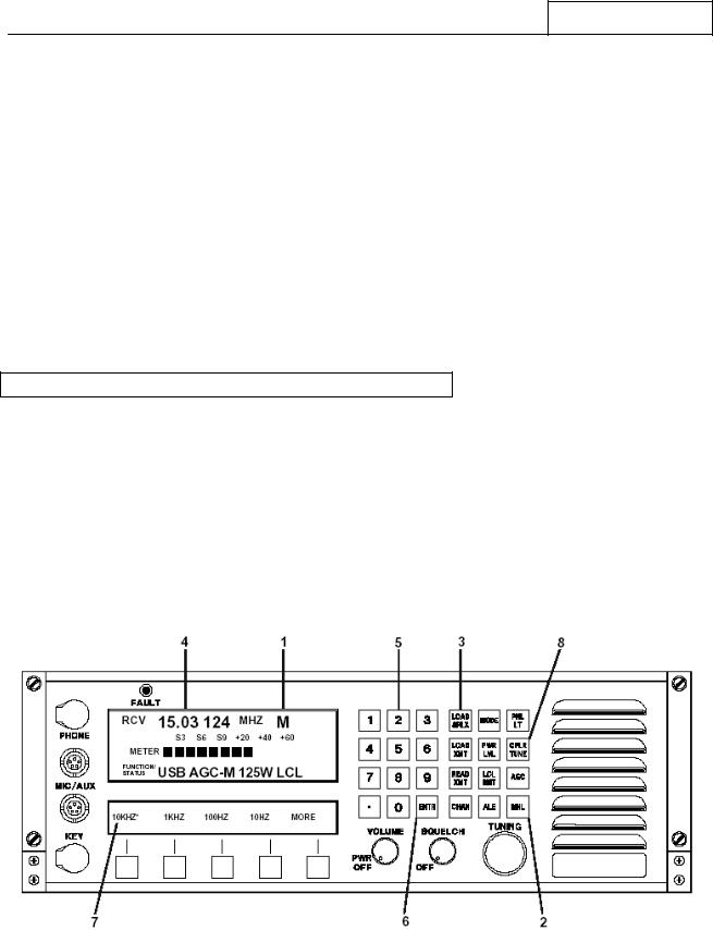
To establish an operating frequency, place the system in the Manual Tuning mode. Refer to Figure 7.3.2.2. If the RT-9000B Operational Display does not indicate an ‘M’ (Manual Tuning mode) at 1 , depress the Manual (‘MNL’) key at 2. The display will change to the ‘M’ at 1. The Feature Menu Display also will change to the “Frequency Step Feature Menu” shown at 7. The Manual Tuning mode operates only in “Simplex” operating mode (alternate receive and transmit using the same frequency).
Depressing the Load Simplex (‘LOAD SPLX’) key at 3 will cause the “Frequency Display” at 4 of the Operational Display to go blank. The Numeric Keypad at 5 , may now be used to key in the desired operating frequency up to seven (7) digits long. As each frequency digit is keyed in , the digits will appear in order of entry (left to right) on the Operational Display at 4 . After the complete operating frequency has been keyed in, depress the Enter (‘ENTR’) key at 6 to enter the selection into the RT-9000B Transceiver’s memory.
RT-9000 B
Figure 7.3.2.2 Operating Frequency Controls
THE TRANSCEIVER IS NOW OPERATIONAL ON THE ENTERED FREQUENCY
Document No. 8128000560 |
7-13 |
Software Revision – N1B (07 Oct 04) |
|
RT-9000B
Because the system is in Manual Tuning mode, the User may change the above-entered frequency with the ‘TUNING’ dial. The rate (or “steps”) that the dial movement changes the operating frequency and other details are covered later in section 7.3.2.5 Manual Tuning.
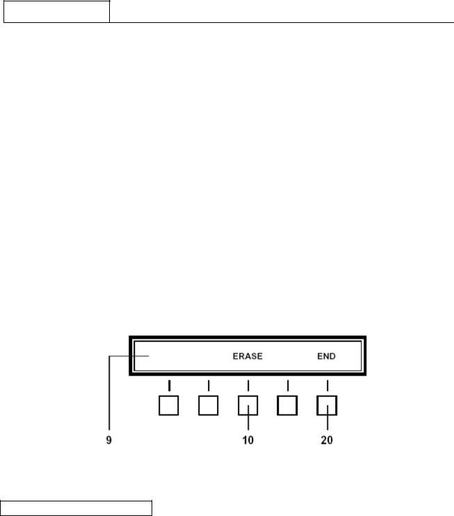
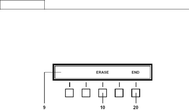
NOTE: After the Load Simplex (‘LOAD SPLX’) key is depressed; the Feature Menu Display shown in Figure 7.3.2.3 will appear. An ‘ERASE’ selection at 10 will be present. Depressing this key allows the user to erase an in-progress frequency entry, one digit at a time, beginning with the last digit entered (most right-hand). When the desired digits are erased, simply resume frequency entry using the Numeric Keypad. DO NOT depress the ‘END’ key at 20.
Depressing the ‘END’ key at 20 will abort frequency selection and cause the channel to revert to the frequency currently stored.
NOTE: RT-9000B Transceiver Operating Frequency entries between 100 kHz and 1.59999 MHz will be accepted and its Receiver will function normally. However, when its Transmitter is keyed, the frequency display will flash at 4 . An ‘ILLEGAL XMT FREQ’ message will briefly appear in the Operational Display.
NOTE: Frequency entries below 100 kHz will not be accepted and the frequency display will flash at 4 .
Figure 7.3.2.3 Erase Feature Menu
7.3.2.3 TRANSMIT TUNING
After an operating frequency has been entered as described in section 7.3.2.2, the Transmitter portion of the RT-9000B will automatically be tuned to the entered frequency. The RT-9000B will operate in “Simplex” mode. If the RT-9000B Transceiver output is feeding a Broadband Antenna directly, the Transmitter will automatically be tuned. Similarly, if the RT-9000B Transceiver is driving a broadband Linear Power Amplifier (such as the LPA-9600) that is also feeding a Broadband Antenna directly, the entire Transmitter equipment chain will automatically be tuned.
THE TRANSCEIVER IS NOW FULLY OPERATIONAL
7-14 |
Document No. 8128000560 |
|
Software Revision – N1B (07 Oct 04) |

RT-9000B
7.3.2.4 ANTENNA COUPLER TUNING
When the RT-9000B is using a Non-resonant Antenna, an Antenna Coupler must be installed between the RT-9000B and Antenna. When the RT-9000B is driving an external Linear Power Amplifier (such as the LPA-9600) that uses a Non-resonant Antenna; an Antenna Coupler must be installed between the LPA-9600 and Antenna. In both cases, the Antenna Coupler becomes the feed point for the Antenna. Transmitter RF Output Power capability is a primary factor in determining which Antenna Coupler model must be used. Typically, the RT-9000B Transceiver and the LPA-9600 Linear Power Amplifier will use models CU-9125 and CU-9150 Antenna Couplers, respectively.
Refer to Figure 7.3.2.2. When an Antenna Coupler is present in the system, depressing the Coupler Tune (‘CPLR TUNE’) key at 8 , will initiate an Antenna Coupler “Tune Cycle”. During the Tune Cycle, the RT9000B Operational Display will display the following message:
‘COUPLER TUNING’
After the Antenna Coupler Tune Cycle finishes and successfully tunes the Antenna, a message will appear in the RT-9000B Operational Display and tell the operator the system is ready for use. This message will appear for about three (3) seconds and then automatically return to the normal channel information display. This message is as follows:
‘SYSTEM READY’
If the Antenna Coupler is not able to tune the Antenna within 20 seconds, a message will be displayed informing the operator of that result. This message will appear for about three (3) seconds and then automatically return to the normal channel information display. If this result occurs, the Antenna Coupler and Antenna should be checked for any obvious problem. If all appears to be in order, consult the troubleshooting section of the Antenna Coupler manual.
‘SYSTEM FAULT’
If the Antenna Coupler develops a Fault or the remote RT-9000B does not receive the expected handshake signals from the Antenna Coupler, the following message will be displayed. This message will appear for about three (3) seconds and then automatically return to the normal channel information display. If this result occurs, consult the troubleshoot section of the Antenna Coupler manual. This message is as follows:
‘COUPLER FAULT’
7.3.2.5 MANUAL TUNING
The manual tuning function permits the RT-9000B Transceiver’s operating frequency to be changed by rotating the ‘TUNING’ control. After an operating frequency has been established as described in section 7.3.2.2, rotating the ‘TUNING’ control clockwise increases frequency; counter-clockwise rotation decreases it. The rate of operating frequency change for a given amount of ‘TUNING’ control rotation is selectable. Four
(4) different Tuning Rates (or “steps”) are available.
Document No. 8128000560 |
7-15 |
Software Revision – N1B (07 Oct 04) |
|
RT-9000B
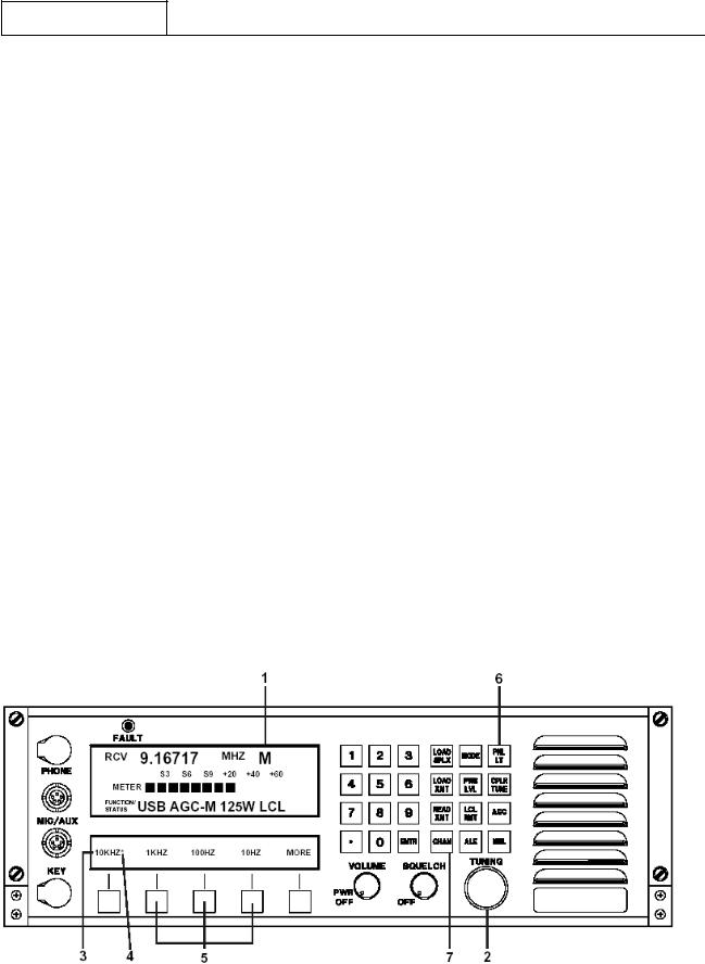
To manually tune the RT-9000B Transceiver, the unit must be in Manual mode and have an operating frequency established according to section 7.3.2.2. Refer to Figure 7.3.2.4.
The rate the operating frequency is changed is indicated in the Feature Menu Display at 3. Four (4) different Frequency Step choices are available and are selected using the Feature keys directly below the Frequency Step values shown in the Feature Menu Display. An asterisk (*) will appear immediately to the right of the selected Frequency Step value.
As an example, in Figure 7.3.2.4, the asterisk beside ‘10KHZ’ shown at 4 indicates this is the current Frequency Step value. Selecting any of the other values immediately enables that value. By using the “TUNING” dial and the available Frequency Step values, the operator may easily and rapidly train in on a specific frequency or range of frequencies.
If the user wishes to make large changes in operating frequency which would not be practical using the ‘TUNING’ control, the Load Simplex (‘LOAD SPLX’) key may also be used to enter the new operating frequency. To do this, depress the ‘LOAD SPLX’ key. Key in the new frequency with the Numeric Keypad and depress the Enter (‘ENTR’) key. The operator may then continue to operate the system as previously described on the newly entered frequency.
All operating frequency entries in the Manual Tuning mode operate exclusively as Simplex frequencies. If the User attempts to load a different Transmit frequency using the ‘LOAD XMT’ key, the following message will briefly appear in the Operational Display and then automatically clear.
‘DISALLOWED IN MANUAL’
NOTE: Systems having an Antenna Coupler present and operating in ‘Manual Tuning’ must be re-tuned whenever the current operating frequency is changed before Transmitting. Refer to the previous section 7.3.2.4 for details.
To exit Manual Tuning (‘MNL’) mode, depress the ‘CHAN’ key at 7 . Refer to section 7.3.2.7 for details about operating with Pre-set Channels.
RT-9000 B
Figure 7.3.2.4 Manual Tuning Controls
7-16
Document No. 8128000560
Software Revision – N1B (07 Oct 04)
RT-9000B
7.3.2.6 DISPLAY ILLUMINATION
The Front Panel display will illuminate when the RT-9000 B is first powered up. If no keyboard activity is detected for about 30 minutes, the display illumination will automatically turn OFF. Depressing the ‘PNL LT’ key will cause both the Operational and Feature Menu Display illumination to turn back ON. A second depression turns it OFF. The user may also turn OFF the display illumination immediately at power up.
NOTE: The backlighting components for both the Operational and Feature Menu Display LCD displays gradually lose luminescence over time. If the display illumination is not needed, the display illumination Panel Light (‘PNL LT’) should be turned OFF to prolong the life of the backlighting components. See Section V for replacement of backlighting components.
7.3.2.7 OPERATING WITH PRE-SET CHANNELS
Operation using Pre-set Channels requires that the desired operating frequencies and their related settings have been previously entered into the RT-9000B Transceiver’s memory. If this has not been previously done, refer to section 7.3.2.9 ahead before continuing.
Refer to Figure 7.3.2.5. Depress the Channel (‘CHAN’) key at 2. The numerical portion of the Channel Number at 3 will go blank. Key in desired Channel Number from ‘0’ to ‘127’ using the Numeric Keypad at 4 . The Channel Number may be one, two, or three digits long; no leading zeros are required. The keyed in Channel Number will appear on the display at 3 .
Depress the Enter (‘ENTR’) key at 5. The operating frequency stored for the Channel Number entered will now appear on the display at 6 .
NOTE: If the entered Channel Number has been set up for Half-Duplex operation (different Transmit and Receive frequencies), the Receive frequency will be displayed when using these steps. To confirm the Transmit frequency, depress the Read Transmit (‘READ XMT’) key at 7 . The Transmit frequency will display at 6 for about four (4) seconds and then revert back to the Receive frequency.
If an Antenna Coupler is present in the system, an Antenna Coupler “Tune Cycle” may now be started by depressing the Coupler Tune (‘CPLR TUNE’) key at 8 . If the Antenna Coupler successfully tunes the Antenna, a ‘SYSTEM READY’ message will briefly appear and automatically clear. If any other messages appear, the User should refer back to section 7.3.2.4 for guidance.
If the Antenna Coupler has Pre-set Channel capability, the coupler will record into its memory its internal settings for a successful “Tune Point”. This permits the coupler to quickly return to this “Tune Point” when this particular Channel Number is selected in the future.
If the user has reason to believe the Antenna is no longer properly tuned or Antenna conditions materially change, the User may depress the Coupler Tune (‘CPLR TUNE’) and start a new “Tune Cycle”. Every new “Tune Cycle” is treated as an update to any tuning information currently stored in the Antenna Coupler’s memory for any given Channel Number.
THE SYSTEM IS NOW FULLY OPERATIONAL ON THE SELECTED CHANNEL
Document No. 8128000560 |
7-17 |
Software Revision – N1B (07 Oct 04) |
|
RT-9000B
RT-9000 B
Figure 7.3.2.5 Pre-set Channel Operating Controls
7.3.2.8 MANUAL CHANNEL SELECTION
Manual Channel Selection is a type of Pre-set Channel operation. This type of operation allows Pre-set Channel selection using the ‘TUNING’ control instead of the Numeric Keypad.
Refer to Figure 7.3.2.6. If not already in Pre-set Channel operation, select it now by depressing the ‘CHAN’ key. Depress the Feature Menu ‘MORE’ key successively at 1 until the Feature Menu Display at 2 appears.
Depress Manual Channel key (‘M CH-’) at 3 . The Channel designator, ‘CH’ immediately preceding the Channel Number on the Operational Display at 4 will change to the Manual Channel designator, ‘MC’. An asterisk (*) will appear next to ‘MCH -’ in the Feature Menu Display to indicate this selection has been enabled.
Rotating the ‘TUNING’ control at 5 increases or decreases the selected Channel Number in numerical order. The Channel Number is displayed at 6 and its Pre-set operating frequency will appear in the Operational Display at 7 .
NOTE: Transceiver operating ‘MODE’, Receiver ‘AGC’ Characteristic’, and Transmitter RF Output ‘Power Level’ settings are pre-set and stored for each channel. As the ‘TUNING’ control is rotated, these settings will change to reflect the settings for the currently selected Channel Number.
Systems using an Antenna Coupler operate in the same manner as previously discussed in section 7.3.2.7. The only operational difference between these modes is the operator’s ability to more rapidly change Channels and its possible effect on an Antenna Coupler. Modern Antenna Couplers with Pre-set Channel capability typically re-tune a Pre-set Channel from memory between 10 to 30 milliseconds and should be able to track RT-9000B Manual Channel Selection.
7-18 |
Document No. 8128000560 |
|
Software Revision – N1B (07 Oct 04) |
RT-9000B
NOTE: This Channel selection method provides a convenient, rapid means of verifying current Pre-set Channels or logging unknown Channel information.
RT-9000 B
Figure 7.3.2.6 Manual Channel Operating Controls
To exit Manual Channel Selection operation, depress the ‘M CH-’ Feature Menu key at 3 again. The asterisk (*) beside ‘M CH-’ in the Feature Menu Display will disappear. The ‘MC’ designator at 4 will revert back to the ‘CH’ designator. The Channel Number selected immediately before leaving Manual Channel Selection will continue to be selected.
7.3.2.9 ESTABLISHING OR MODIFYING PRE-SET CHANNELS
The RT-9000B can store up to 128 Pre-set Channels (in Channels 0 through 127). The operations described in this section describe how to establish or modify Pre-set Channels.
These operations allow the user to create, enter and store a Pre-set Channel into the RT-9000B Transceiver’s memory. Once a Pre-set Channel has been properly set up, the RT-9000B will be able to recall all settings whenever that particular Channel Number is selected. Pre-set Channel information is stored in non-volatile memory.
Modifying a setting, in actuality, merely repeats the original entry steps used when establishing a Pre-set Channel except using different setting information.
The RT-9000B Transceiver also automatically provides Channel Number information, as an output, for use by external peripheral equipment. This information allows external equipment having Pre-set Channel capability to operate properly and efficiently. Typical examples might include Pre-selectors, Linear Power Amplifiers, and Antenna Couplers. No operator action associated with this capability is required during normal operation.
Document No. 8128000560 |
7-19 |
Software Revision – N1B (07 Oct 04) |
|

RT-9000B
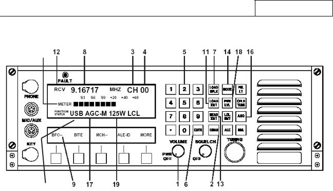
The following headings listed below appear later in this section and describe how to enter settings for new or existing Pre-set Channels. Unless otherwise noted, refer to Figure 7.3.2.7 for the location of controls and displays.
• Operating Frequency
Simplex Operation |
Alternate Receive & Transmit |
|
using same frequency |
||
|
||
Half-Duplex Operation |
Alternate Receive & Transmit |
|
using different frequencies |
||
|
•Transceiver Emission Mode
•Receiver AGC Speed Characteristic
•Transmitter Power Output Level
•External Equipment Set up and Initialization
7.3.2.9.1Channel Number Selection
The steps in this section form a selection process, which must be performed for either new or existing Channels. This process establishes the Pre-set Channel Number where later setting choices will be stored. User actions after this step will depend on whether an existing Channel is being selected for modification or a new Channel is being established.
If the user is modifying an existing Pre-set Channel setting, proceed as follows: Complete the selection process described in this heading. Proceed directly to the heading that covers the setting to be modified.
If the user is establishing a new Pre-set Channel, complete the selection process described in this heading. Complete ALL remaining headings in this section.
Channel Selection Process
Depress the Channel key (‘CHAN’) at 2. The Operational Display will display ‘CH’ at 3 and Channel Digits at 4 will go blank.
Using the Numeric Keypad at 5, key in the desired Channel Number to be selected. The keyed in Channel Number now will appear at 4. Depress the Enter (‘ENTR’) key at 6 to select the keyed in Channel Number. All later settings entry and storage steps will be associated with this Channel Number.
Proceed to the next step as previously described.
7-20 |
Document No. 8128000560 |
|
Software Revision – N1B (07 Oct 04) |
RT-9000B
RT-9000 B
15
Figure 7.3.2.7 Pre-set Channel Entry Controls
7.3.2.9.2 Operating Frequency Entry
Simplex Operation
Depress the Load Simplex (‘LOAD SPLX’) key at 7. The frequency display at 8 will go blank and the “Receive/Transmit” mode designator at 12 will continue to display the Receive ‘RCV’ indication.
Using the Numeric Keypad at 5, key in the desired Operating Frequency (between 100 kHz and 29.99999 MHz). As each digit is keyed in, it will appear in the Operational Display at 8 in order of entry (left to right).
After the Operating Frequency has been completely keyed in, depress the Enter (‘ENTR’) key at 6 to store it in the currently selected Channel Number. Immediately after depressing the ‘ENTR’ key, the frequency display in the Operational Display will momentarily blink but remain on the entered frequency.
NOTE: After the ‘LOAD SPLX’ key is depressed, the Feature Menu Display shown in Figure 7.3.2.8 will appear and provide an Erase (‘ERASE’) choice at 10 . This allows the user to erase a frequency just entered, one digit at a time, beginning with the last digit entered (most right-hand). After the desired digit(s) are erased, simply resume the frequency entry process using the Numeric Keypad. DO NOT depress the End (‘END’) key at 20.
The ‘END’ key aborts the frequency entry process and causes the currently selected Pre-Channel to revert to its original settings.
Document No. 8128000560 |
7-21 |
Software Revision – N1B (07 Oct 04) |
|
RT-9000B
Completing the “Simplex Operation” process prepares the RT-9000B Transceiver to Receive and Transmit using the SAME operating frequency for the currently selected Pre-set Channel. If this type of operation desired, skip over the following “Half-Duplex Operation” heading and proceed directly to the later headings dealing with entering or modifying the required Pre-set Channel settings.
If Half-Duplex operation is desired, continue to next heading, “Half-Duplex Operation” and complete the described steps before proceeding.
Figure 7.3.2.8 Erase Feature Menu
Half-Duplex Operation
Complete all previously outlined steps for Simplex Operation. This process enters the Receive Operating Frequency.
Depress the Load Transmit (‘LOAD XMT’) key at the “Receive/Transmit” mode designator at 12 (‘XMT’) indication.
11. The frequency display at 8 will go blank and will change from the Receive (‘RCV’) to Transmit
Using the Numeric Keypad at 5, key in the desired Transmit frequency (between 1.6 MHz and 29.99999 MHz). As each digit is keyed in, it will appear in the Operational Display at 8 in order of entry (left to right).
After the desired Transmit frequency has been completely keyed in, depress the Enter (‘ENTR’) key at 6 to enter it into the currently selected Channel Number. Immediately after depressing the ‘ENTR’ key, the frequency display in the Operational Display will momentarily blank and return to the stored Receive frequency. Additionally, the “Receive/Transmit” mode designator at 12 also will revert back to the Receive (‘RCV’) indication.
NOTE: After the ‘LOAD XMT’ key is depressed, the Feature Menu Display shown in Figure 7.3.2.8 will appear and provide an Erase (‘ERASE’) choice at 10 . This allows the user to erase a frequency just entered, one digit at a time, beginning with the last digit entered (most right-hand). After the desired digit(s) are erased, simply resume the frequency entry process using the Numeric Keypad. DO NOT depress the End (‘END’) key at 20.
7-22 |
Document No. 8128000560 |
|
Software Revision – N1B (07 Oct 04) |

RT-9000B
Completing the “Half-Duplex Operation” process prepares the RT-9000B Transceiver to Transmit and Receive using DIFFERENT Operating Frequencies (but not simultaneously) for the currently selected Pre-set Channel.
NOTE: The Transmit frequency for currently selected Pre-set Channel may be viewed by depressing the Read Transmit (‘READ XMT’) key at 13. The stored Transmit frequency will be displayed for about three (3) seconds before reverting back displaying the stored Receive frequency.
If this type of operation is desired and the required Operating Frequencies have been entered for the currently selected Pre-set Channel, proceed now to the next Heading. Continue entering or modifying the required Pre-set Channel settings.
7.3.2.9.3 Transceiver Emission Mode Entry
Depress the ‘MODE’ key at 14 successively until the desired Emission Mode appears on the Operational Display at 15 . The displayed Mode indicates the current RT-9000B Emission Mode selection. Four (4) choices are available: ‘USB’, ‘LSB’, ‘CW’, or ‘AM’. Depress the Enter (‘ENTR’) key at 6 to store this selection into the currently selected Pre-set Channel .
NOTE: A fifth Mode choice, 'DATA', will be displayed only if the optional Data filter is installed in the RT-9000B Transceiver. The RT-9000B Transceiver CPU Software DIP switch settings must also be properly set for this option. (Refer to Section V of this Operation and Maintenance Manual).
NOTE: When Continuous Wave (‘CW’) Emission Mode is selected, CW Key Release Time and Filter settings automatically default to ‘Medium’ and ‘Normal’ settings, respectively. Other choices are available and are covered later in section 7.3.3.10 of this manual.
After the desired Emission Mode setting has been entered for the currently selected Pre-set Channel, proceed to the next Heading. Continue entering or modifying the required Pre-set Channel settings.
7.3.2.9.4 Receiver AGC Speed Characteristic Entry
Depress the ‘AGC’ key at 16 successively until the desired Receiver AGC Speed Characteristic appears on the Operational Display at 17 . The displayed AGC Speed indicates the current Receiver AGC Speed selection. Three (3) choices are available: Slow (‘AGC-S’), Medium (‘AGC-M’), or Fast (‘AGC-F’). Depress the Enter (‘ENTR’) key at 6 to store this selection into the currently selected Pre-set Channel.
After the desired AGC Speed Characteristic setting has been entered for the currently selected Pre-set Channel, proceed to the next Heading. Continue entering or modifying the required Pre-set Channel settings.
Document No. 8128000560 |
7-23 |
Software Revision – N1B (07 Oct 04) |
|
RT-9000B
7.3.2.9.5 Transmitter Power Output Level Entry
Depress the Power Level (‘PWR LVL’) key at 18 successively until desired Power Level appears on the Operational Display at 19. The available choices depend on whether an external Linear Power Amplifier is present in the system and its power output capability. The available choices are: ‘65W’ or ‘125W’ when an external amplifier IS NOT present. When an external amplifier IS present, the additional choices will be: ‘500W’ for the LPA-9500 Amplifier or ‘500W’ and ‘1000W’ for the LPA-9600 Amplifier. Depress the Enter key (‘ENTR’) at 6 to permanently store a new Power Level selection into the currently selected Pre-set Channel.
After the desired Power Level setting has been entered for the currently selected Pre-set Channel, proceed to the next heading if other equipment is being used in conjunction with the RT-9000B Transceiver. If no other equipment is being used, skip the next heading and go directly to the end of this section.
7.3.2.9.6 External Equipment Set up and initialization
If the RT-9000B Transceiver is part of a system with external equipment having Pre-set Channel capability, this equipment should now be set up and initialized as described in the appropriate equipment manuals.
The most common type of external equipment will be an Antenna Coupler. The User should refer to section 7.3.2.4 for guidance.
After completing entry of all settings in this section, the RT-9000B Transceiver is now ready for control on this Pre-set Channel. Additional Pre-set Channels may be set up by repeating the preceding steps 7.3.2.9.1 through 7.3.2.9.5 for each new Channel Number.
7.3.2.10 BFO OPERATION
A Beat Frequency Oscillator (BFO) originally was required to receive Continuous Wave (CW) and later, various suppressed-carrier mode signals such as Single Sideband (SSB). Modern Receiving equipment, like the RT-9000B, instead uses a Product Detector circuit to perform the detection (or demodulation) for these signal types.
Even though the BFO function is no longer used for its original purpose, it still performs a useful function in today’s equipment. The BFO function is a receive-only feature that provides fine frequency adjustment or compensation for incoming signals. This permits the RT-9000B to faithfully receive off-frequency signals without affecting the RT-9000B’s transmitting frequency. Up to a ± 1.99 kHz frequency deviation from the indicated or nominal receive frequency can be handled.
A common use of the BFO is to use it in voice modes as a “Clarifier” to correct unpleasant speech output caused by a frequency offset. Other possible uses might include improving the operation of external tone operated devices or modems.
To use the BFO function, depress the ‘MORE’ key from the main menu successively until the Feature Menu Display shown in Figure 7.3.2.9 appears.
7-24 |
Document No. 8128000560 |
|
Software Revision – N1B (07 Oct 04) |
RT-9000B
*
RT-9000 B
Figure 7.3.2.9 RT-9000B Displays with BFO Enabled
Depress the ‘BFO’ feature key at 3 . An asterisk (*) will appear next to ‘BFO’ in the Feature Menu Display indicating this function is now enabled. The Channel Number information (Channel designator, ‘CH’ and Number) shown at 4 in the Operational Display will be replaced with the BFO Offset Frequency and “± Polarity Indicator” (initially: + 0.00 kHz).
The BFO Offset Frequency may now be set at any point within a ± 1.99 kHz range by rotating the ‘TUNING’ control at 5. The BFO Offset Frequency increases in 10 Hz steps with clockwise rotation of the control and decreases with counter-clockwise rotation.
The BFO is disabled by depressing the ‘BFO’ feature key at 3 once again.
NOTE: The BFO feature is Receive-only function and can only be selected if USB, LSB, CW, or Data Emission Modes are selected. Transmitter frequency and operation is not affected by BFO operation.
NOTE: The BFO feature operates only in the Channel-oriented operating modes. If ‘Manual’ Tuning mode is currently selected, any attempt to enable the BFO feature will be rejected and cause the following message to briefly appear in the Operational Display:
‘DISALLOWED IN MANUAL’
NOTE: If the BFO feature is currently selected and ‘Manual’ Tuning mode is then selected, ‘Manual mode will be selected but the BFO feature will automatically be disabled.
Document No. 8128000560 |
7-25 |
Software Revision – N1B (07 Oct 04) |
|
RT-9000B
7.3.3 EQUIPMENT SET-UP
This section addresses those features and functions that are either of secondary operational importance or need be accomplished only infrequently, usually at the time of commissioning.
7.3.3.1 BITE (Built-In-Test-Equipment)
The RT-9000 B is equipped with self-diagnostic routines that allow the operator to verify that all Modules are functioning correctly. If a fault is found, these test routines will help identify which Module is faulty. The BITE function operates independently of any mode in which the equipment was operating before the BITE function was enabled.
The RT-9000 B BITE function has two (2) levels of test routines. The first level checks the operation of RT9000 B Primary Modules that provide basic service functions to the rest of the unit (Power Supply, CPU, etc.) This test routine is called General BITE. The second level is composed of specialized test routines that check either the Receiver or Transmitter modules. If the system contains an Antenna Coupler, a separate test routine to verify Antenna Coupler operation is included. These specialized second level BITE tests are called Receive BITE (‘RX-BITE’), Transmit BITE (‘TX-BITE’) and Coupler BITE (’CU-BITE’).
When entering BITE mode from the main menu, the User will first encounter the General BITE test routine. General BITE must be executed and passed before the second level BITE tests will become available. After General BITE is passed, the Feature Menu Display will change and provide Receive BITE (‘RX-BITE’) and Transmit BITE (‘TX-BITE’) choices. If the system has an Antenna Coupler, a Coupler BITE (‘CU-BITE’) choice will be available. An ‘END’ choice is present If the User wishes to exit BITE mode at this point. This allows the User to return to the main menu and resume normal operation.
Transmit BITE primarily tests RT-9000 B Transmitter modules but also briefly tests the Antenna System. Antenna System condition is an important part of the overall radio system performance. If faulty, the Antenna can adversely other station equipment and performance. This is particularly true for Transmit related operations. More detailed information about Antenna related testing is covered later in section 7.3.3.1.3 Transmit BITE.
7.3.3.1.1 General BITE
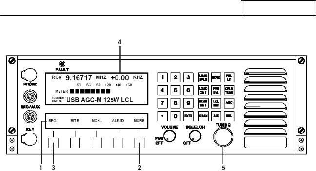
Depress the Feature Menu ‘MORE’ key from the main menu successively until the Feature Menu shown in Figure 7.3.3.1 appears. Unless otherwise noted, all text in section 7.3.3.1 refers to Figure 7.3.3.1.
RT-9000 B
Figure 7.3.3.1 |
Main Menu containing BITE Selection |
7-26 |
Document No. 8128000560 |
|
Software Revision – N1B (07 Oct 04) |

RT-9000B
Depress the ‘BITE’ key at 3 to start executing the General BITE test routine.
After depressing the ‘BITE’ key, a ‘BITE IN PROGRESS’ message will briefly appear in the Operational Display. This message will automatically clear and test result messages will begin appearing as individual tests are completed for each of the five (5) Modules tested.
As the General BITE test runs, it will stop on the first Fault found. This Fault must be corrected before proceeding. If additional Faults are present, the General BITE test routine must be repeated until no further Faults are found.
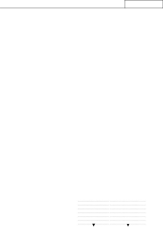
Refer to the following chart for General BITE test routine details.
RT-9000B Transceiver
General BITE – Test Details
Test |
Module Under |
Test Result Messages |
||
Order |
Test |
No Fault found |
Fault found |
|
|
|
|||
|
|
|
|
|
1 |
Front Panel |
‘FRONT PANEL OK’ |
‘FRONT PANEL FAULT’ |
|
|
|
|
|
|
2 |
CPU Assembly |
‘CPU OK’ |
‘CPU FAULT’ |
|
|
|
|
|
|
3 |
Frequency |
‘SYNTHESIZER OK’ |
‘SYNTHESIZER FAULT’ |
|
Synthesizer |
||||
|
|
|
||
4 |
Power Supply |
‘POWER SUPPLY OK’ |
‘POWER SUPPLY FAULT’ |
|
|
|
|
|
|
5 |
I/O PCB |
‘I/O OK’ |
‘I/O FAULT’ |
|
|
|
|
|
|
NOTE: If a Frequency Synthesizer Fault occurs, the initial ‘BITE IN PROGRESS’ message will not display and the General BITE test routine will not operate correctly. Proceed to Section V of this manual for fault isolation and repair.
If the General BITE test routine is passed, a ‘SELECT BITE TYPE’ Message will appear at 4 in the Operational Display. This message informs the User that the General BITE test was passed and draws the User’s attention to the new BITE Select Sub-menu. This menu will be covered shortly.
If a General BITE FAULT is found
The following actions will typically occur when a Fault is found:
1.The General BITE test routine will halt.
2.A Module Fault message will be displayed at 4 in the Operational Display .
3.The Red Front Panel ‘FAULT’ lamp at 5 will be lit.
4.No second level BITE tests will be available.
Proceed to Section V of this manual for fault isolation and repair procedures.
Document No. 8128000560 |
7-27 |
Software Revision – N1B (07 Oct 04) |
|

RT-9000B
After the displaying the ‘SELECT BITE TYPE’ message, the Feature Menu Display will change to that shown in Figure 7.3.3.2. This BITE Sub-Menu provides the second level BITE test choices for Receive BITE (‘RXBITE’), Transmit BITE (‘TX-BITE’), and, when applicable, Coupler BITE (’CU-BITE’). These choices are covered in the next sections.
After the General BITE test routine is finished, the User may do the following:
•Repeat the General BITE test routine. Depressing the ‘END’ key at 3 will cause the Feature Menu Display to revert to that shown in Figure 7.3.3.1. Depressing the ‘BITE’ key again will repeat the test.
•Exit BITE mode. Depressing the ‘END’ key at 3 will return the User to the main menu and resume normal operation.
•Proceed to the Receive BITE (‘RX BITE’), Transmit BITE (‘TX BITE’), or Coupler BITE (‘CU-BITE’) test routines as covered in the following sections.
|
|
|
|
|
|
|
|
|
|
|
|
|
|
|
|
|
|
|
|
|
|
|
|
|
|
|
|
|
|
|
|
|
|
|
|
|
|
|
RX–BITE |
CU-BITE |
TX–BITE |
END |
||||||||||||||
|
|
|
|
|
|
|
|
|
|
|
|
|
|
|
|
|
|
|
|
|
|
|
|
|
|
|
|
|
|
|
|
|
|
|
|
|
|
|
|
|
|
|
|
|
|
|
|
|
|
|
|
|
|
|
|
|
|
|
|
|
|
|
|
|
|
|
|
|
|
|
|
|
|
|
|
|
|
|
|
|
|
|
|
|
|
|
|
|
|
|
|
|
|
|
|
|
|
|
|
|
|
|
|
|
|
|
|
|
|
|
|
|
|
|
|
|
|
|
|
|
|
|
|
|
|
|
|
|
|
|
|
|
|
|
|
|
|
|
|
|
|
|
|
|
|
|
|
|
|
|
|
1 4 2 3
Note: The ‘CU-BITE’ selection will appear only if an Antenna
Coupler is present in the system.
Figure 7.3.3.2 BITE Sub-Menu
7.3.3.1.2 Receive BITE (‘RX-BITE’)
From the BITE Sub-Menu shown in Figure 7.3.3.2, depress the ‘RX–BITE’ key at 1 . The RT-9000 B will start executing the Receive BITE test routine.
After depressing the ‘RX-BITE’ key, a ‘RX BITE IN PROGRESS’ message will briefly appear in the Operational Display and a loud but brief audio tone will be heard from the Front Panel speaker. The audio tone will be heard regardless of the Speaker On/Off (‘SPKR’) setting (covered later in section 7.3.3.3).
The ‘RX BITE IN PROGRESS’ message will automatically clear and test result messages will begin appearing as individual tests are completed for each of the three (3) Modules tested.
As the Receive BITE test runs, it will stop on the first Fault found. This Fault must be corrected before proceeding. If additional Faults are present, the Receive BITE test routine must be repeated until no further Faults are found.
Refer to the following chart for Receive BITE test routine details.
7-28 |
Document No. 8128000560 |
|
Software Revision – N1B (07 Oct 04) |
RT-9000B
RT-9000B Transceiver
Receive BITE (‘RX-BITE) – Test Details
Test |
Module Under |
Test Result Messages |
||
Order |
Test |
No Fault found |
Fault found |
|
|
|
|||
|
|
|
|
|
1 |
|
‘RX BITE IN PROGRESS’ |
||
Audio PCB |
(Accompanied by brief loud speaker tone) |
|||
|
||||
|
|
|
||
2 |
‘AUDIO OK’ |
‘AUDIO FAULT’ |
||
|
||||
|
|
|
|
|
3 |
IF PCB |
‘IF OK’ |
‘IF FAULT’ |
|
|
|
|
|
|
4 |
Front End PCB |
‘FRONT END OK’ |
‘FRONT END FAULT’ |
|
|
|
|
|
|
If a Receive BITE (RX-BITE) FAULT is found
The following actions will typically occur when a Fault is found:
1.The Receiver BITE (‘RX - BITE’) test routine will halt.
2.A Module Fault message will be displayed at 4 in the Operational Display .
3.The Red ‘FAULT’ lamp on the Front Panel at 5 will be lit.
Proceed to Section V of this manual for fault isolation and repair procedures.
After this test is completed, the User may do the following:
•Repeat the Receive BITE test. Depressing the ‘RX-BITE’ key again at 1 as shown in Figure 7.3.3.2 will cause the Receive BITE test routine to repeat.
•Exit BITE mode. Depressing the ‘END’ key at 3 will return to the main menu and resume normal operation.
•Proceed to the Transmit BITE (‘TX-BITE’) or Coupler BITE (‘CU-BITE’) test routines covered in the following sections.
Document No. 8128000560 |
7-29 |
Software Revision – N1B (07 Oct 04) |
|
RT-9000B
7.3.3.1.3 Transmit BITE (‘TX BITE’)
Overview
Transmit BITE primarily tests the RT-9000 B Transmitter modules but also performs a brief Antenna System test. An improperly operating Antenna System can cause false Transmit BITE test results. This is the primary reason Antenna System testing is included in the Transmit BITE test routine. In addition to internal test use, this same valuable Antenna status information is also passed directly to the User.
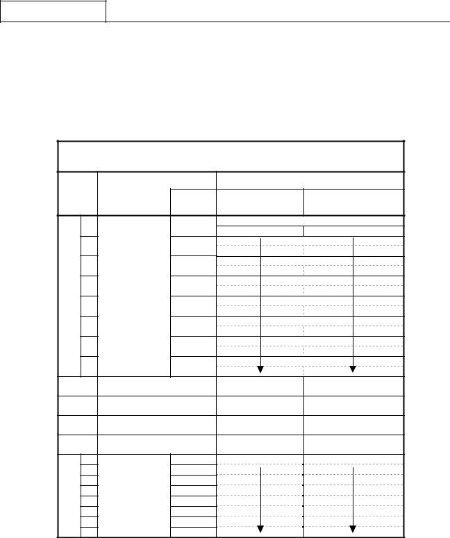
Certain Transmit BITE tests are performed at eight (8) selected test frequencies. These test frequencies were selected to thoroughly exercise all RT-9000 B Transmitter modules as well as the station Antenna System. These test frequencies are listed in the following chart.
Transmit BITE
Test Frequencies
(MHz)
1.757.75
2.7510.75
3.7516.75
5.7525.75
The type of Antenna tests performed will depend on the type of Antenna the station is using. Antennas are generally either Broadband or Non-Resonant types. The following is a brief discussion of these antenna types and testing.
A Broadband Antenna operates over a wide frequency range and is usually designed for a 50-Ohm input impedance. This allows the Antenna to be directly fed from the Transmitter using 50-Ohm coaxial cable. This Antenna type does not require an Antenna Coupler. Antenna testing consists of performing a VSWR test at all eight (8) test frequencies.
A Non-Resonant Antenna may also operate over a wide frequency range but will have large input impedance variations. These variations prevent the Antenna from being directly fed from the Transmitter using coaxial cable. An Antenna Coupler must be used to match the Antenna’s impedance to the Antenna Coupler’s 50Ohm input impedance. 50-Ohm coaxial cable can then be used to connect the Transmitter to the Antenna Coupler’s input. Antenna testing consists of performing a “Tuning Test” at all eight (8) test frequencies.
When a system contains an external Linear Power Amplifier and is using a Broadband Antenna, the same tests are performed as without the Linear Power Amplifier. The external Linear Power Amplifier is always switched it out of the system (or bypassed) during Transmit BITE testing. This effectively connects the RT9000 B Transceiver directly to the station Antenna. In this way, the external Amplifier is never involved in the Transmit BITE test process.
Systems equipped with an external Linear Power Amplifier but using a Non-Resonant Antenna, of course, must use an Antenna Coupler. With this system configuration, the Linear Power Amplifier is also switched out during Transmit BITE. This effectively connects the RT-9000 B Transceiver to the Antenna Coupler input that normally is connected to the Linear Power Amplifier output.
The following two (2) procedures describe how the Transmit BITE (‘TX-BITE’) test routine operates when using either Broadband or Non-Resonant types of Antennas.
7-30 |
Document No. 8128000560 |
|
Software Revision – N1B (07 Oct 04) |
RT-9000B
Procedure - Systems using a Broadband Antenna
From the BITE Sub-Menu shown in Figure 7.3.3.2, depress the ‘TX – BITE’ key at 2 . The RT-9000 B will start executing the Transmit BITE test routine.
After starting the test, a ‘TX BITE IN PROGRESS’ message will appear in the Operational Display until this test section is finished. During this time, the RT-9000 B will rapidly key and unkey the Transmitter as it steps through all eight (8) test frequencies. These individual tests together form the Antenna VSWR test.
Specific test frequencies where high VSWR conditions are found are excluded from the ‘Filter Module’ tests later in the test routine. When high VSWR condition(s) are found, these findings will be displayed after the Transmit BITE test routine completely finishes.
After the Antenna VSWR section finishes, test result messages will begin appearing as the next four (4) Transmitter Modules are tested.
The Transmit BITE test routine concludes by testing the Filter Module. Of the eight (8) possible frequencies, only those will be used that where earlier a high VSWR was NOT found. During this test, the RT-9000 B will key and unkey the Transmitter as it steps through these test frequencies.
As the Transmit BITE test runs, it will stop on the first Fault found. This Fault must be corrected before proceeding. If additional Faults are present, the Transmit BITE test routine must be repeated until no further Faults are found.
Refer to the following chart for Transmit BITE test routine details.
|
|
|
|
|
|
RT-9000B Transceiver |
|
|
|
||
|
|
Transmit BITE |
(‘TX-BITE’) – Test Details – Broadband Antenna |
|
|||||||
|
|
|
|
|
|
|
|
|
|
|
|
|
Test |
Module Under |
|
|
|
Test Result Messages |
|
||||
|
|
|
|
|
|
|
|
||||
|
Order |
Test |
|
|
Test |
No Fault found |
Fault found |
|
|||
|
|
|
Frequency |
|
|||||||
|
|
|
|
|
|
|
|||||
|
|
|
|
|
|
(MHz) |
|
|
|
|
|
|
|
a. |
|
|
|
1.75 |
|
|
|
|
|
|
|
b. |
|
|
|
2.75 |
|
|
|
|
|
|
|
c. |
Antenna |
|
|
3.75 |
|
|
|
|
|
|
1 |
d. |
VSWR |
|
|
5.75 |
|
‘TX BITE IN PROGRESS’ |
|
||
|
e. |
|
|
7.75 |
|
|
|||||
|
|
Test |
|
|
|
|
|
|
|
||
|
|
f. |
|
|
10.75 |
|
|
|
|
|
|
|
|
|
|
|
|
|
|
|
|
||
|
|
g. |
|
|
|
16.75 |
|
|
|
|
|
|
|
h. |
|
|
|
25.75 |
|
|
|
|
|
|
2 |
|
Audio PCB |
|
‘AUDIO OK’ |
‘AUDIO FAULT’ |
|
||||
|
|
|
|
|
|
|
|
|
|
|
|
|
3 |
|
IF PCB |
|
|
|
‘IF OK’ |
‘IF FAULT’ |
|
||
|
|
|
|
|
|
|
|
|
|
||
|
4 |
|
Front End PCB |
|
‘FRONT END OK’ |
‘FRONT END FAULT’ |
|
||||
|
|
|
|
|
|
|
|
|
|||
|
5 |
|
Power Amplifier Assembly |
‘POWER AMPL OK’ |
‘POWER AMPL FAULT’ |
|
|||||
|
|
|
|
|
|
|
|
|
|
|
|
|
|
a. |
|
|
|
1.75 |
‘FILTER MODULE OK’ |
‘FILTER MODULE FAULT’ |
|
||
|
|
b. |
|
|
|
2.75 |
|
|
|
|
|
|
|
|
|
|
|
|
|
|
|
||
|
|
c. |
Filter |
|
|
3.75 |
|
|
|
|
|
|
|
d. |
|
|
5.75 |
|
|
|
|
|
|
|
6 |
Module |
|
|
|
|
|
|
|
||
|
e. |
|
|
7.75 |
|
|
|
|
|
||
|
|
Assembly |
|
|
|
|
|
|
|
||
|
|
f. |
|
|
10.75 |
|
|
|
|
|
|
|
|
|
|
|
|
|
|
|
|
||
|
|
g. |
|
|
|
16.75 |
|
|
|
|
|
|
|
h. |
|
|
|
25.75 |
|
|
|
|
|
Document No. 8128000560 |
|
|
|
|
|
|
7-31 |
||||
Software Revision – N1B (07 Oct 04) |
|
|
|
|
|
|
|
|
|||

RT-9000B
If a Transmitter Module BITE Fault is found
The following actions will typically occur when a Fault is found:
1.The Transmit BITE (‘TX - BITE’) test routine will halt.
2.A Module Fault message will be displayed at 4 in the Operational Display .
3.The Red ‘FAULT’ lamp on the Front Panel at 5 will be lit.
Proceed to Section V of this manual for fault isolation and repair procedures.
If the Transmit BITE test routine finishes without displaying a Fault message, one of the following messages will appear in the Operational Display. The following summarizes these messages and their meaning.
•‘TEST COMPLETED’. This message means all Transmitter Modules passed the Transmit BITE test routine. It also means that the VSWR test results for all eight (8) test frequencies were within acceptable limits.
•‘VSWR HI AT XX XX MHZ’. This message means all Transmitter Modules passed the Transmit BITE test routine but a high VSWR condition was found on one test frequency. In this case, XX XX indicates the specific test frequency. The decimal point is not displayed.
•‘VSWR HI AT MULT MHZ’. This message means all Transmitter Modules passed the Transmit BITE test routine but a high VSWR condition was found on two (2) or more of the test frequencies.
If either of the preceding VSWR-related messages appears, proceed to Section V of this manual for fault isolation and repair procedures.
After this test is completed, the User may do the following:
•Repeat this Transmit BITE test. Depressing the ‘TX-BITE’ key again at 2 as shown in Figure 7.3.3.2 will cause the Transmit BITE test routine to repeat.
•Repeat the Receive BITE test, as previously covered.
•Exit BITE mode. Depressing the ‘END’ key at 3 will return to the main menu and resume normal operation.
7-32 |
Document No. 8128000560 |
|
Software Revision – N1B (07 Oct 04) |

RT-9000B
Procedure - Systems using a Non-Resonant Antenna
From the BITE Sub-Menu shown in Figure 7.3.3.2, depress the ‘TX – BITE’ key at 2 . The RT-9000 B will start executing the Transmit BITE test routine.
The Antenna Coupler will begin a “Tuning Cycle” using the first test frequency. While the Antenna Coupler tuning cycle is in progress, a ‘COUPLER TUNING’ message will appear in the Operational Display. After the Antenna Coupler finishes tuning (or the maximum allotted tuning time expires), a test result message will be displayed. A ‘SYSTEM READY’ or ‘SYSTEM FAULT’ message will be displayed. If the Antenna Coupler is totally inoperative, a ‘COUPLER FAULT’ message will instead be displayed. In both above cases, the Transmit BITE test routine will not stop if either of these Faults is found.
After the first test frequency tuning cycle is finished, the test routine will then step to the second test frequency and repeat this process. This sequence will repeat until all eight (8) test frequencies have been tuned by the Antenna Coupler. These individual tests together form the Antenna Coupler tuning test section.
Test frequencies that result in ‘SYSTEM FAULT’ test outcome will be excluded from the ‘Filter Module’ tests later in the Transmit BITE test routine. When these “No Tune” condition(s) are found, the findings will be displayed after the Transmit BITE test routine completely finishes.
After the Antenna Coupler tuning tests are completed, test result messages will begin appearing as the next four (4) Transmitter Modules are tested.
The Transmit BITE test routine concludes by testing the Filter Module. Of the eight (8) possible frequencies, only those that successfully tuned and resulted in ‘SYSTEM READY’ message will be used. During this test, the RT-9000 B will key and unkey the Transmitter as it steps through these test frequencies.
As the Transmit BITE test runs, it will stop on the first Transmitter Module Fault found. This Fault must be corrected before proceeding. If additional Faults are present, the Transmit BITE test routine must be repeated until no further Faults are found.
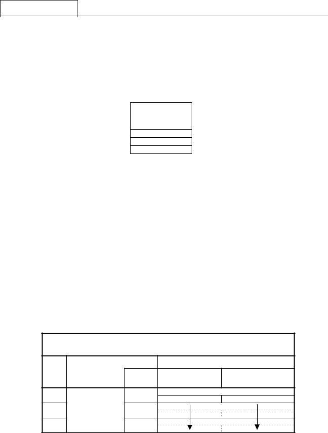
Refer to the following chart for Transmit BITE test routine details.
Document No. 8128000560 |
7-33 |
Software Revision – N1B (07 Oct 04) |
|
RT-9000B
RT-9000B Transceiver
Transmit BITE (‘TX-BITE’) – Test Details - Non-Resonant Antenna
Test |
Module Under |
|
Test Result Messages |
|||
Test |
|
|
||||
Order |
Test |
No Fault found |
Fault found |
|||
Frequency |
||||||
|
|
|
||||
|
|
|
(MHz) |
|
|
|
|
a. |
|
1.75 |
‘COUPLER TUNING’ |
||
|
|
‘SYSTEM READY’ |
‘SYSTEM FAULT’ |
|||
|
|
|
|
|||
|
b. |
|
2.75 |
|
|
|
|
c. |
|
3.75 |
|
|
|
1 |
d. |
Antenna Coupler |
5.75 |
|
|
|
e. |
Tuning Test |
7.75 |
|
|
||
|
|
|
||||
|
|
|
|
|||
|
f. |
|
10.75 |
|
|
|
|
g. |
|
16.75 |
|
|
|
|
h. |
|
25.75 |
|
|
|
2 |
|
Audio PCB |
|
‘AUDIO OK’ |
‘AUDIO FAULT’ |
|
3 |
|
IF PCB |
|
‘IF OK’ |
‘IF FAULT’ |
|
4 |
|
Front End PCB |
|
‘FRONT END OK’ |
‘FRONT END FAULT’ |
|
5 |
|
Power Amplifier Assembly |
‘POWER AMPL OK’ |
‘POWER AMPL FAULT’ |
||
|
a. |
|
1.75 |
‘FILTER MODULE OK’ |
‘FILTER MODULE FAULT’ |
|
|
b. |
|
2.75 |
|
|
|
|
c. |
Filter |
3.75 |
|
|
|
|
d. |
5.75 |
|
|
||
6 |
Module |
|
|
|||
e. |
7.75 |
|
|
|||
|
Assembly |
|
|
|||
|
f. |
10.75 |
|
|
||
|
|
|
|
|||
|
g. |
|
16.75 |
|
|
|
|
h. |
|
25.75 |
|
|
|
7-34 |
Document No. 8128000560 |
|
Software Revision – N1B (07 Oct 04) |

RT-9000B
If a Transmitter Module BITE Fault is found
The following actions will typically occur when a Fault is found:
1.The Transmit BITE (‘TX - BITE’) test routine will halt.
2.A Module Fault message will be displayed at 4 in the Operational Display .
3.The Red ‘FAULT’ lamp on the Front Panel at 5 will be lit.
Proceed to Section V of this manual for fault isolation and repair procedures.
If the Transmit BITE test routine finishes without displaying a Fault message, one of the following messages will appear in the Operational Display. The following summarizes these messages and their meaning.
•‘TEST COMPLETED’. This message means all Transmitter Modules passed the Transmit BITE test routine. It also means that the Antenna Coupler successfully tuned all eight (8) test frequencies.
•‘NO TUNE AT XX XX MHZ’. This message means all Transmitter Modules passed the Transmit BITE test routine but a “No Tune” condition was found on one test frequency. In this case, XX XX indicates the specific test frequency. The decimal point is not displayed.
•‘NO TUNE AT MULT MHZ’. This message means all Transmitter Modules passed the Transmit BITE test routine but a “No Tune” condition was found on two (2) or more of the test frequencies
If either of the “No Tune”-related messages appears, proceed to Section V of this manual AND the Antenna Coupler manual for fault isolation and repair procedures.
After this test is completed, the User may do the following:
•Repeat this Transmit BITE test. Depressing the ‘TX-BITE’ key again at 2 as shown in Figure 7.3.3.2 will cause the Transmit BITE test routine to repeat.
•Repeat the Receive BITE test, as previously covered.
•Exit BITE mode. Depressing the ‘END’ key at 3 will return to the main menu and resume normal operation.
•Proceed to the Coupler BITE (‘CU-BITE’) test routine covered in the following section.
Document No. 8128000560 |
7-35 |
Software Revision – N1B (07 Oct 04) |
|
RT-9000B
7.3.3.1.4 Coupler BITE (‘CU BITE’)
Overview
The Coupler BITE (‘CU BITE’) test routine performs a brief Antenna Coupler “Tuning Test” using three (3) test frequencies. No RT-9000 B modules are tested. The test frequencies used for this test are listed in the following chart.
Coupler BITE
Test Frequencies
(MHz)
5.75
16.75
29.75
Procedure
From the BITE Sub-Menu shown in Figure 7.3.3.2, depress the ‘CU – BITE’ key at 4 . The RT-9000 B will start executing the Coupler BITE test routine.
The Antenna Coupler will start a “Tuning Cycle” using the first test frequency. While the tuning cycle is in progress, a ‘CU BITE IN PROGRESS’ message will briefly appear in the Operational Display.
After the tuning cycle finishes or the maximum allotted tuning time expires, a test result message will be displayed. A ‘SYSTEM READY’ or ‘SYSTEM FAULT’ message will indicate these results. If the Antenna Coupler is totally inoperative, a ‘COUPLER FAULT’ message will instead be displayed.
In both above cases where a Fault is found, the Coupler BITE test will stop. The BITE test will stop at the first Fault found and must be corrected before proceeding. If additional Faults are present, the Coupler BITE test routine must be repeated until no further Faults are found.
Refer to the following chart for Coupler BITE test routine details
|
|
RT-9000B Transceiver |
|
|||
|
Coupler BITE |
(‘CU-BITE’) – Test Details |
|
|||
Test |
Module Under |
|
|
Test Result Messages |
||
Test |
|
|
|
|||
Order |
Test |
|
No Fault found |
Fault found |
||
Frequency |
||||||
|
|
|||||
|
|
(MHz) |
|
|
|
|
1 |
|
5.75 |
|
‘COUPLER TUNING’ |
||
|
|
‘SYSTEM READY’ |
‘SYSTEM FAULT’ |
|||
|
|
|
|
|||
2 |
Antenna Coupler |
16.75 |
|
|
|
|
3 |
|
29.75 |
|
|
|
|
7-36 |
Document No. 8128000560 |
|
Software Revision – N1B (07 Oct 04) |
 Loading...