

Page 1

RIGOL
Application Note
TX1000 RF Demo Kit
Feb. 2014
RIGOL Technologies, Inc.
Page 2

Page 3

RIGOL
I
Guaranty and Declaration
Copyright
© 2010 RIGOL Technologies, Inc. All Rights Rese rved.
Trademark Information
RIGOL is a registered trademark of RIGOL Technologies, Inc.
Publication Number
APD05102-1110
Notices
RIGOL products are protected by patent law in and outside of P.R.C.
RIGOL reserves the right to modify or change parts of or all the specifications and pricing
policies at company’s sole decision.
Information in this publication replaces all previously corresponding material.
RIGOL sha ll not be liable f or losses caused by either incidental or consequenti al in connection
with the furnishing, use or performance of this manual as well as any information contained.
Any part of this document is forbid den to be copied or photocopied or rearranged without prior
written approval of RIGOL.
Product Certification
RIGOL guarantees this product conforms to the national and industrial sta nda r ds in China as well
as the ISO9001:2008 standard and the ISO14001:2004 standard. Other international standard
conformance certification is in progress.
Contact Us
If you have any problem or requirement when using our products or this manual, please contact
RIGOL.
E-mail: [email protected]
Websites: www.rigol.com
TX1000 RF Demo Kit Application Note
Page 4

RIGOL Content
II
Content
Guaranty and Declaration ............................................................................................ I
Product Overview ........................................................................................................ 1
Hardware Modules ...................................................................................................... 2
To Control TX1000 Using PC Software ........................................................................ 3
Software Installation ..................................................................................................... 3
System and Installation Requirements ...................................................................... 3
Installation Procedures ........................................................................................... 3
To Connect TX1000 ....................................................................................................... 6
To Start the Software .................................................................................................... 9
Interf ace Layout ......................................................................................................... 10
To Control TX1000 Using DSA800 ............................................................................. 12
Typical Applications .................................................................................................. 13
To Test the Measurement Function of the Spectrum Analyzer .......................................... 13
To Test the Band-pass Filter Characteristics ................................................................... 14
The Influence of the Performance of Amplifier on the System ......................................... 15
The Influence of the Performance of Filter on the System ............................................... 17
Specifications ............................................................................................................ 18
Accessories ............................................................................................................... 20
TX1000 RF Demo Kit Application Note
Page 5

RIGOL
1
Product Overview
TX1000 RF Demo Kit (hereinafter referred to as TX1000) is a signal emission kit released by
RIGOL to demonstrate the DSA1000, DSA1000A and DSA800 series spectrum analyzers.
TX1000 features:
Energized by USB.
Connected with PC for control through software.
When connected with DSA800, it can be controlled via t he built -in control i nterf ace o f DS A800
without using the PC.
Provide 10 MHz reference signal output for easy clock synchronization with other devices.
Built-in 50 MHz signal which can be connected to th e input port by “switches” to be used for
the learning, operation and demonstration of the spectrum analyzer.
Provide 500 MHz and 1 GHz local oscillator signal outputs.
Modular circuit design; provide interfaces for users to make separate measurement of any
component; enable to replace any component.
TX1000 RF Demo Kit Application Note
Page 6
RIGOL
2
PA
FilterFilter
Mixer
Synthesizer
Hardware Modules
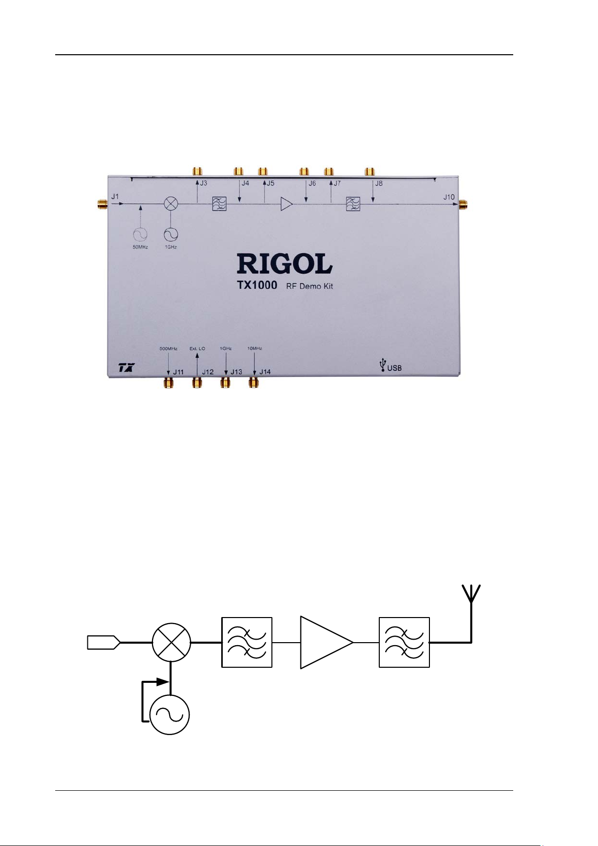
The appearance of TX1000 is as shown in Figure 1. The hardware modules of TX1000 include the
mixer, filter and amplifier. The schematic diagram is as shown in Figure 2.
Figure 1 TX1000 Appearance
USB port: used to connect the PC or spectrum analyzer (provide power for the modules and
control the modules).
J1, J4, J6, J8: signal input terminal.
J3, J5, J7, J10: output RF signal.
J11: output 500 MHz local oscillator signal.
J12: input external local oscillator signal.
J13: output 1 GHz local oscillator signal.
J14: output 10 MHz reference signal.
Figure 2 TX1000 Schematic Diagram
TX1000 RF Demo Kit Application Note
Page 7

3
To Control TX1000 Using PC Software
Software Installation
When using TX1000 with the PC, you have to install the PC control software of TX1000.
System and Installation Requirements
1. Hardware Configuration Requirements
Processor: 1 GHz and greater
Memory: 500 MB and greater
Display: 1024×768 or higher resolution
Hard Disk: 200 MB an d greater
2. Running Environment
Operation System: Windows XP (32-bit), Wi ndows 7 (32-bit), Windows Vista (32-bit)
PC administrator privileges: use the administrator account to log into the PC
The RIGOL common PC software (Ultra Sigma 00.01.05.05 or higher version) has been
installed.
RIGOL
Installation Procedure s
1. Before installing the software, install Ultra Sigma 00.01.05.05 or higher version. For the
installation procedures, refer to the related manual of Ultra Sigma.
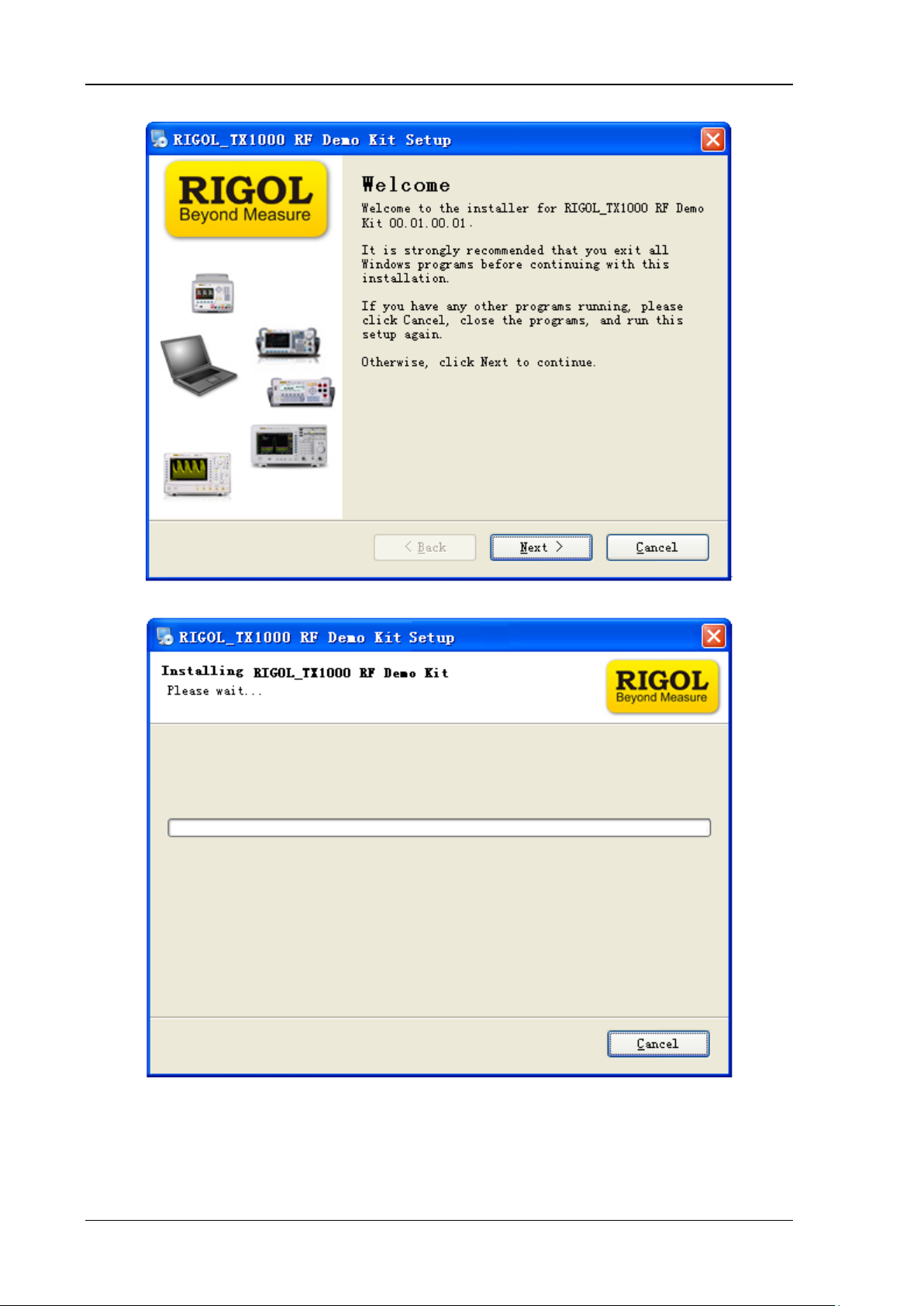
2. RIGOL provides the insta llati on package (in the CD in the pr oduct package) of the PC control
software of TX1000. Double-click the TX1000 setup.exe file to enter the interf ace as shown
in the figure below and follow the instructions to finish the installation.
TX1000 RF Demo Kit Application Note
Page 8
RIGOL
4
3. Click “Next” and the installation process is as shown in the figure below.
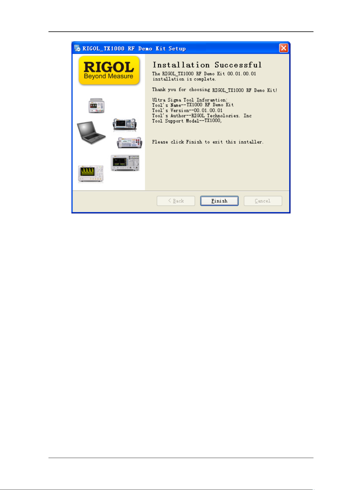
4. The installation process finishes as shown in the figure below. At this point, you have
successfully installed the PC control software of TX1000 and the shortcut named “TX1000 RF
Demo Kit” is displayed on the desktop.
TX1000 RF Demo Kit Application Note
Page 9
RIGOL
5
TX1000 RF Demo Kit Application Note
Page 10
RIGOL
6
To Connect TX1000
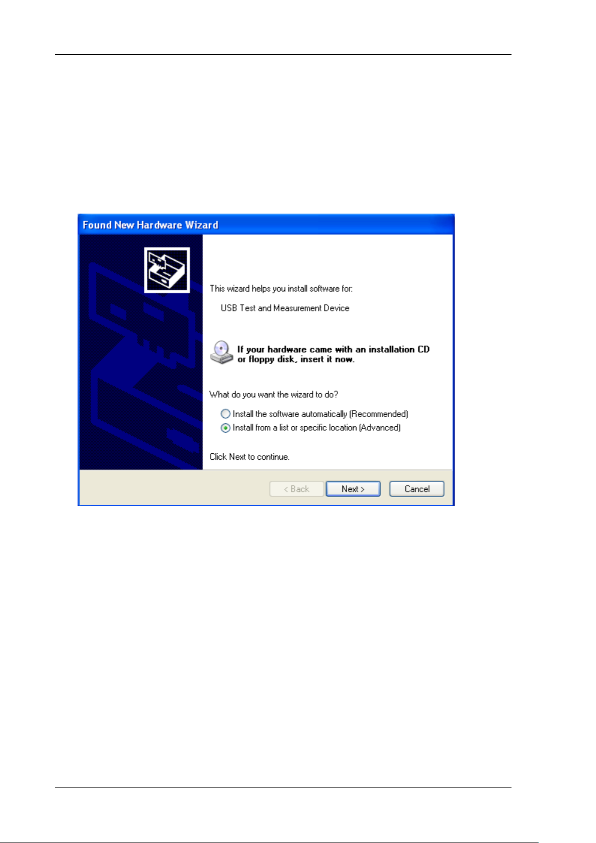
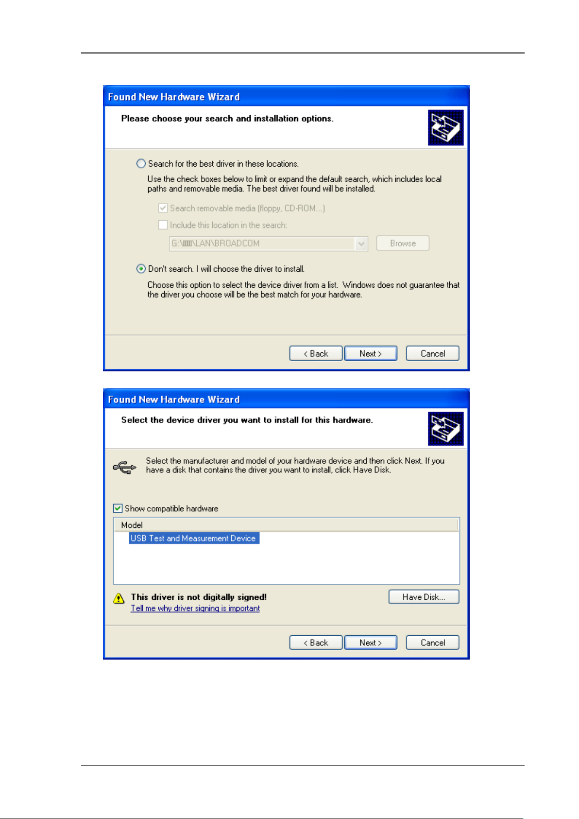
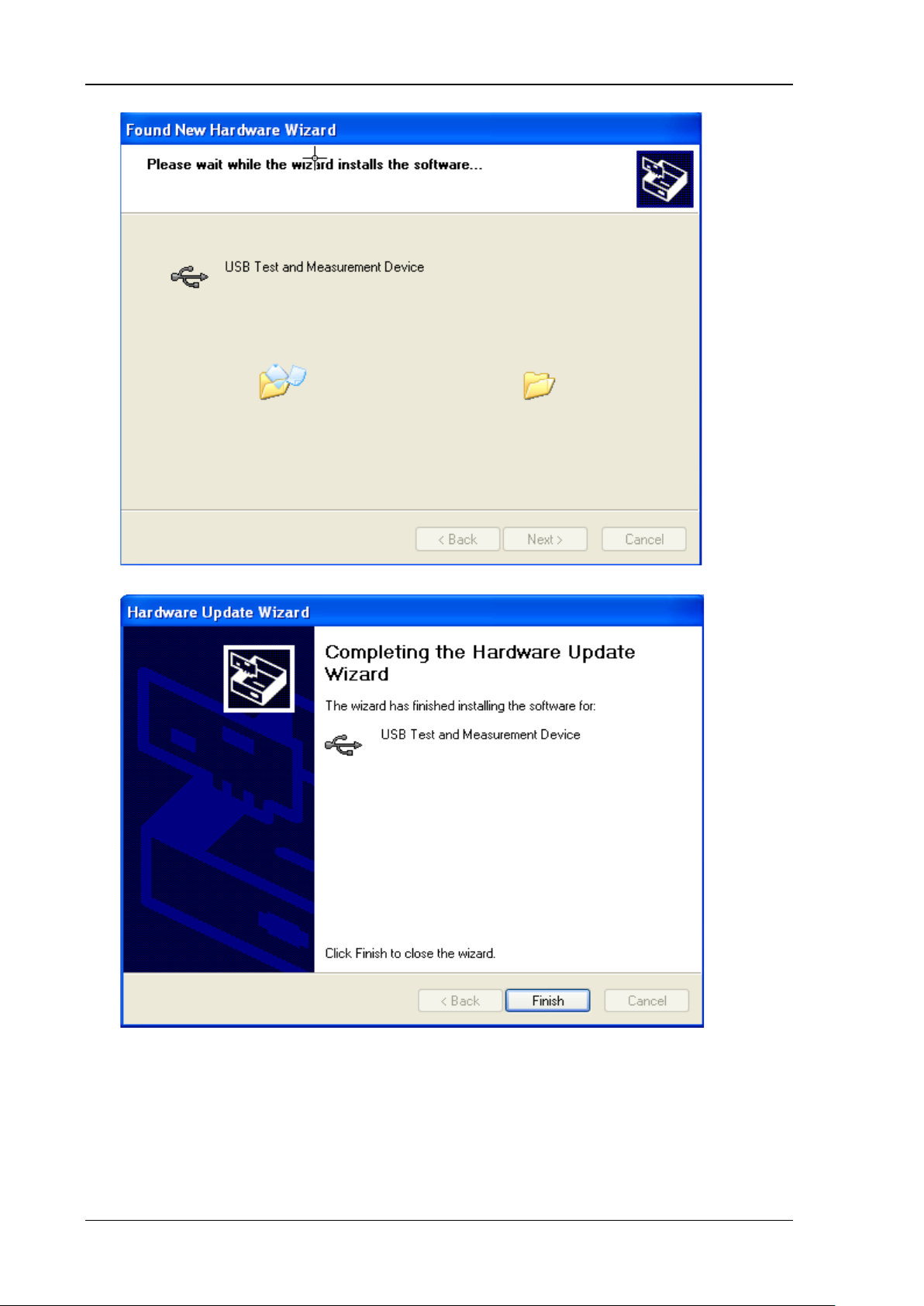
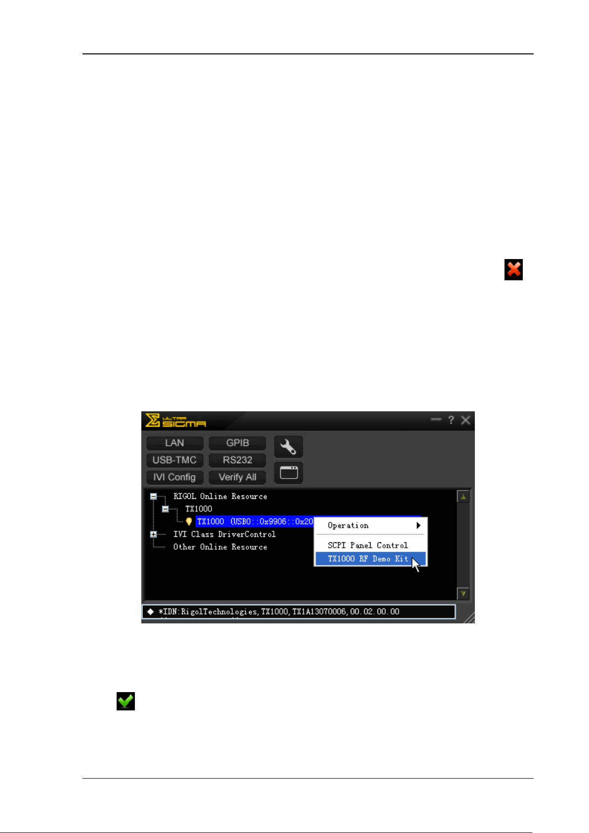
Connect TX1000 and the PC using USB cable. At this point , the “New Hardware Wizard” is displayed
on the PC. Please install t he “USB T est and Measurement Device” driver f ollowing the instructi ons in
the wizard.
The steps are as follows:
1. Select “Install from a list or specific location (Advanced)” and click “Next”;
TX1000 RF Demo Kit Application Note
Page 11
7
2. Select “Don’t search. I will choose the driver to install” and click “Next”;
RIGOL
3. Select “USB Test and Measurement Device” and click “Next”;
TX1000 RF Demo Kit Application Note
Page 12
RIGOL
8
4. Click “Finish” after the installation is f inished.
TX1000 RF Demo Kit Application Note
Page 13
RIGOL
9
To Start the Software
After the PC control software of TX1000 is suc cessfull y installed, y ou can start the so ftware via
the following two methods.
1. Via the [Start] menu or the shortcut on the desktop
Click [Start] [All Programs] [RIGOL Technologies, Inc] [TX1000 RF Demo
Kit]
[TX1000 RF Demo Kit] or double-click the shortcut named “TX1000 RF Demo Kit”
on the desktop to enter the software interface.
Note: the communication between the software an d TX1000 can not be built automatically via
this method (even when the TX1000 is connected to the PC). The connection status is
when the software is start ed. You nee d to build t he co mmunicatio n betwee n the software and
TX1000 manually by referring to the introductions in “Interface Layout”.
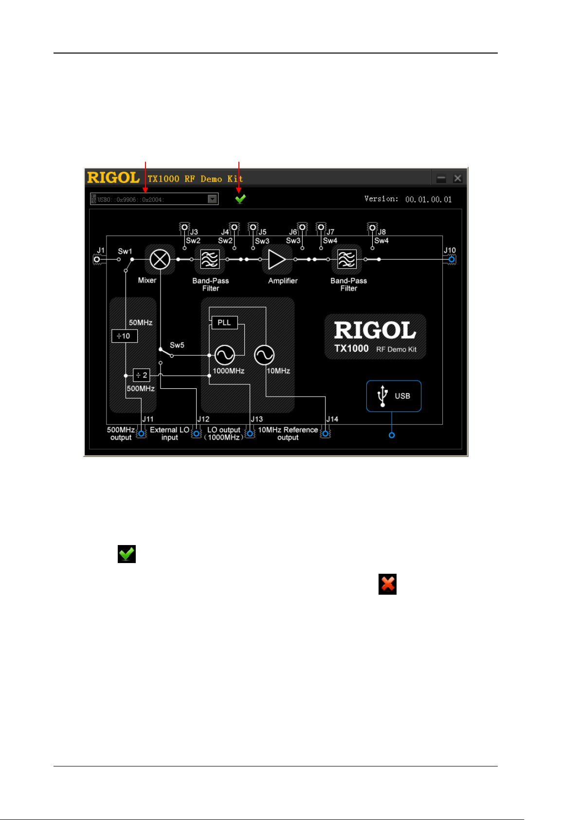
2. Via Ultra Sigma
Connect TX1000 with the PC using the USB cable provided with the accessories;
Start the Ultra Sigma and search for the TX1000 connected;
As shown in the figure below, right-click the resource name of the TX1000 connected and
select “TX1000 RF Demo Kit” to enter the software interface.
Figure 3 Start the Software via Ultra Sigma
Note: the communication between the software and TX1000 can be built automatically via
this method (make sure that your PC ha s been conne cted with TX1000). The connection status
is
TX1000 RF Demo Kit Application Note
when th e software is started.
Page 14
RIGOL
10
Interface Layout
The interface of the PC control software of TX1000 is as shown in the figure below.
Resource Name Connection Status
Figure 4 Interface Layout of the PC Control Software
1. Resource Name and Connection Status
When starting the software via Ultra Sigma, the software displays the resource name
automatically and the dropdown box is grayed out and disabled. At this point, the connection
status is
[Start] menu or shortcut on the de skt o p , the connection status is
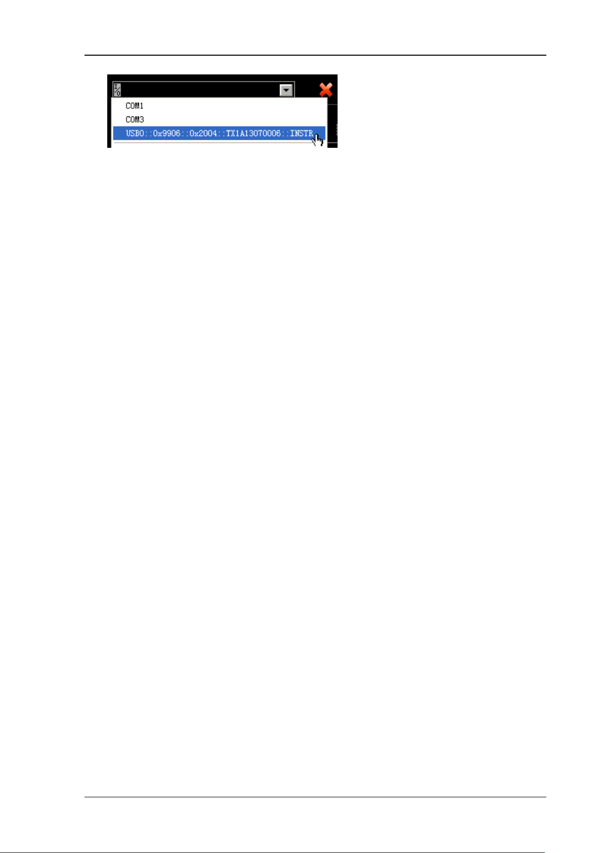
dropdown box and select the resource name of the TX1000 connected to build the
communication between the software and TX1000 manual ly. It takes some time (several
seconds) fo r the soft ware to search the resou rces and please wait fo r the resource list patiently.
When multiple devices are connected to the PC, the resource names of all the devices will be
displayed in the dropdown list and please select the resource name started with
USB0::0x9906::0x2004 (all the resource names of TX1000 start with this character string).
denoting that the connection is successful. When starting the software via the
; you need to click the
TX1000 RF Demo Kit Application Note
Page 15
11
2. Control Sw itc h es
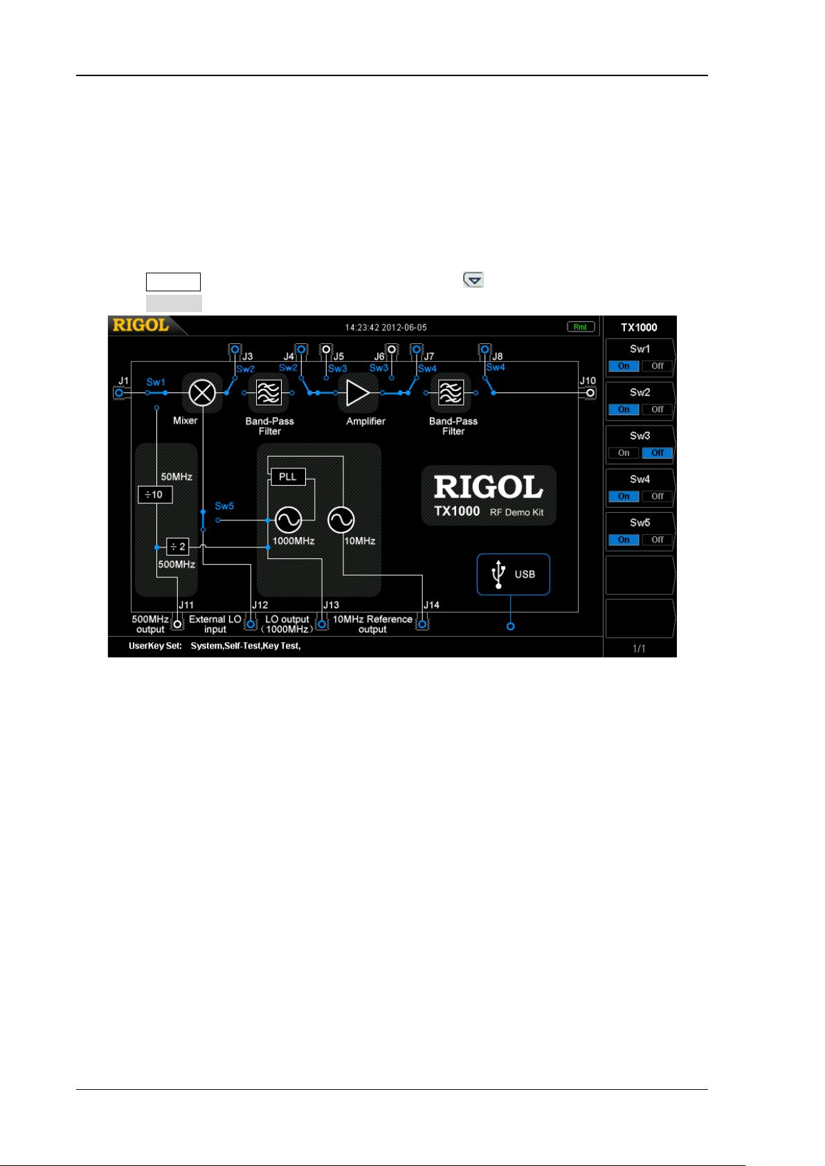
After the software and TX1000 are successfully connected, you can control TX1000 via the
software interface. There are five switches (Sw1, Sw2, Sw3, Sw4 and Sw5) on t he soft ware
interface and you can click the corresponding switch to control its state.
Sw1: when J1 is connected, connect the signal input from the J1 terminal; when J1 is
disconnected, connect the built-in 50 MHz signal.
Sw2: when J3 and J4 are connected, output signal from J3 or connect the signal input
from the J4 terminal; when J3 and J4 are disconnected, perform band-pass f iltering on
the signal passing through the mixer.
Sw3: when J5 and J6 are connected, output signal from J5 or connect the signal input
from the J6 terminal; when J5 and J6 are dis connected, amplif y the signal passing through
the band -pass filter or the signal input from the J4 terminal.
Sw4: when J7 and J8 are connected, output signal from J7 or connect the signal input
from th e J8 terminal; when J7 and J8 are disconnected, perform band-pass filtering on
the signal passing th r ough the amplifier or the signal input from the J6 t er minal and then
output it via J10.
Sw5: when J12 is connected, connect the external local oscillato r signal input f rom the J12
terminal; when J12 is disconnected, connect the internal 1 GHz local oscillator signal.
RIGOL
TX1000 RF Demo Kit Application Note
Page 16
RIGOL
12
To Control TX1000 Using DSA800
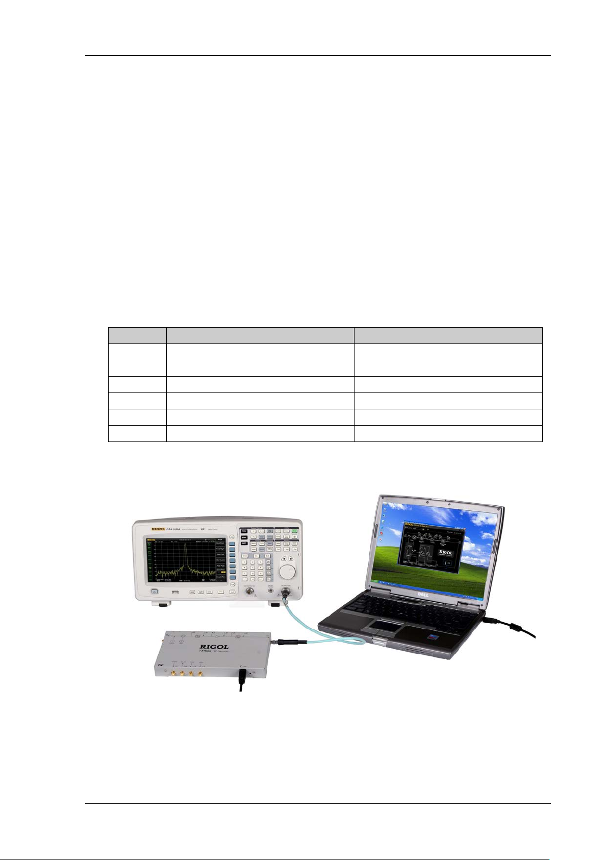
When using TX1000 with the DSA800 series, you can control TX1000 using the built-in control
interface of DSA800 without using the PC and PC control software.
1. Connect TX100 0 a nd DSA800 using the USB cable provided with the accessories.
2. Press System at the front panel of DSA800 and press
Press TX1000 to open the control interface as shown in the figure below.
to open the second page m e n u.
Figure 5 Built-in TX1000 Control Interface of DSA800
3. You can use the menu at the right to control the state of the five switches respectively.
TX1000 RF Demo Kit Application Note
Page 17
RIGOL
13
Typical Applications
To Test the Measurement Function of the Spectrum Analyzer
Operation Steps:
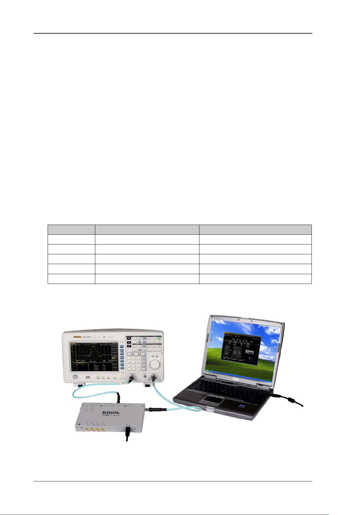
1. Connect the PC and TX1000 using USB cable and connect J10 of TX1000 and the RF input
terminal of the spectrum analyzer using N-SMA cable as shown in Figure 6;
Explanation: when using the DSA800 series spectr um analyzer, you can connect the DSA800
and TX1000 using USB cable without using the PC.
2. Configure the status of each switch via the control interface.
Switch PC Control Software Status DSA800 Contro l In te rface Status
Sw1 Disconnect J1 and connect the
built-in 50 MHz signal
Sw2 Disconnect J3 and J4 Off
Sw3 Disconnect J5 and J6 Off
Sw4 Disconnect J7 and J8 Off
Sw5 Disconnect J12 Off
3. Set the measurement parameters on the spectrum analyzer to get the measurement results.
Off
Figure 6 Test the Measurement Function of the Instrument
TX1000 RF Demo Kit Application Note
Page 18
RIGOL
14
To Test the Band-pass Filter Characteristics
Explanation: the application introduced here is only applicable to spectrum analyzers with the
tracking generator function.
Operation Steps:
1. Connect the PC and TX1000 using USB cable, connect J6 of TX1000 and the output terminal of
the tracking generator of the spectrum analyzer using the N-SMA cable and connect J10 of
TX1000 and the RF input terminal of the spectrum analyzer using N-SMA cable as shown i n
Figure 7;
Explanation: when DSA800 series spectrum analyzer is used, you can connect DSA800 and
TX1000 using USB cable without using the PC.
2. Set the tracking generator parameters on the spectrum analyzer: turn on the tracking
generator and set the parameters such as the TG Level;
3. Configure the status of each switch via the control interface.
Switch PC Control Software Status DSA800 Control Interface Status
Sw1 Ignore Ignore
Sw2 Ignore Ignore
Sw3 Connect J5 and J6 On
Sw4 Disconnect J7 and J8 Off
Sw5 Ignore Ignore
4. Set the measurement parameters on the spectrum analyzer to get the measurement results.
Figure 7 Test the Band-pass Filter Characteristics
TX1000 RF Demo Kit Application Note
Page 19
RIGOL
15
The Influence of the Performance of Amplifier on the System
Operation steps:
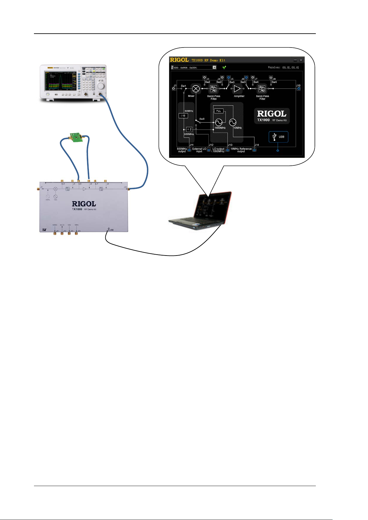
1. Connect the PC and TX1000 using USB cable, connect J10 of TX1000 and the RF input terminal
of the spectrum analyzer using N-SMA cable and connect the amplifier to J5 and J6 using tw o
SMA-SMA cables (to repl ace the internal amplifier of TX1000) as shown in Figure 8;
Explanation: when DSA800 series spectrum analyzer is used, you can connect DSA800 and
TX1000 using USB cable without using the PC.
2. Configure the status of each switch via the control interface.
Switch PC Control Software Status DSA800 Contro l In te rface Status
Sw1 Disconnect J1 and connect the
built-in 50 MHz signal
Sw2 Disconnect J3 and J4 Off
Sw3 Connect J5 and J6 On
Sw4 Disconnect J7 and J8 Off
Sw5 Disconnect J12 Off
3. Set the measurement parameters on the spectrum analyzer to get the measurement results.
Off
TX1000 RF Demo Kit Application Note
Page 20
RIGOL
16
Figure 8 The Influence of the Performance of Amplifier o n th e System
TX1000 RF Demo Kit Application Note
Page 21
RIGOL
17
The Influence of the Performance of Filter on the System
Operation Steps:
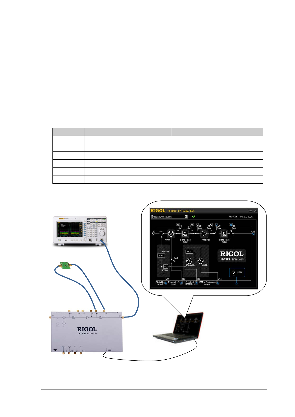
1. Connect the PC and TX1000 using USB cable, connect J10 of TX1000 and the RF input terminal
of the spectrum analyzer using N-SMA cable and connect the filter to J7 and J8 using two
SMA-SMA cables (to replace the internal f ilter of TX1000) as shown in Figure 9;
Explanation: when DSA800 series spectrum analyzer is used, you can connect DSA800 and
TX1000 using USB cable without using the PC.
2. Configure the status of each switch via the control interface.
Switch PC Control Software Status DSA800 Contro l In te rface Status
Sw1 Disconnect J1 and connect the
built-in 50 MHz signal
Sw2 Disconnect J3 and J4 Off
Sw3 Disconnect J5 and J6 Off
Sw4 Connect J7 and J8 On
Sw5 Disconnect J12 Off
3. Set the measurement parameters on the spectrum analyzer to get the measurement results.
Figure 9 The Influence of the Performance of the Filter on the System
Off
TX1000 RF Demo Kit Application Note
Page 22
RIGOL
18
±1 ppm (0℃ to 45℃)
Band-pass Filter
at Center Frequency
Specifications
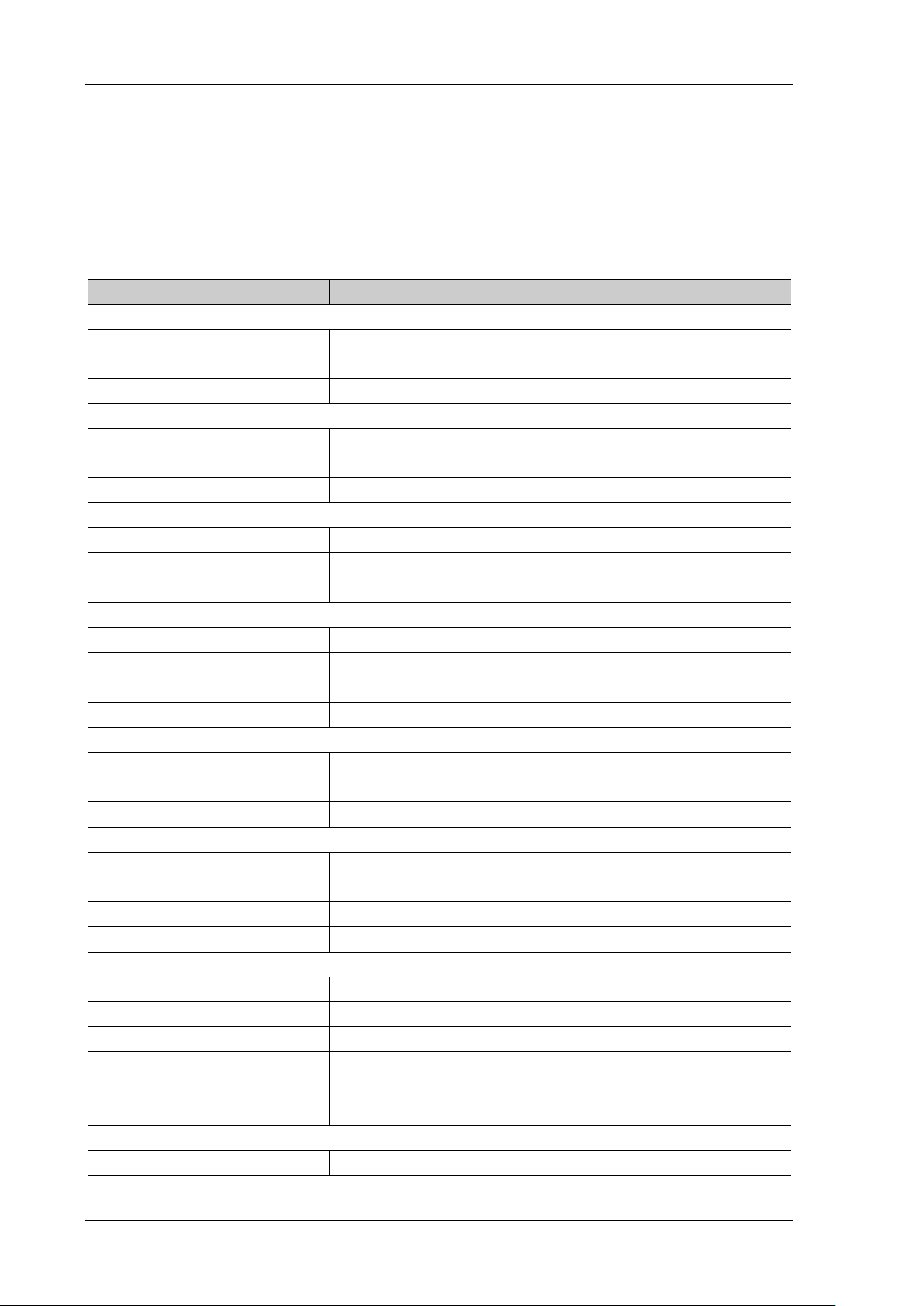
This section lists the specif ications of TX1000. The specifications can be guaranteed und er the
following conditions: t he temperature range is from 0℃ to 45℃; the instrument has been w arme d
up for at least 30 minutes.
Parameters Explanation
Input Port
Input Freque ncy (Standard)
(Expansion)
Input Power ≤ 0 dBm
Output Port
Output Freque ncy (Standard)
(Expansion)
Output Power +3 dBm ± 2 dB
Internal Local Oscillator Output
Output Frequency 1000 MHz
Phase Noise -98 dBc/Hz@10 kHz, Typical
Output Power -17 dBm ± 2 dB
Reference Frequency
Frequency 10 MHz
Temperatu re Stability
Aging Rate ±1 ppm/year
Output Power +3 dBm ± 2 dB
Distortion
SHI +40 dBm
IP3 +20 dBm
P1dB +5 dBm
Mixer
RF/LO Input Frequency Range 50 MHz to 1000 MHz
IF Output Frequency Range DC to 1000 MHz
Local Oscillator Drive Power +7 dBm
Insertion Loss 8 dB (Maximum)
50 MHz ± 10 MHz
10 MHz to 1000 MHz
950 MHz ±10 MHz
DC to 1000 MHz
Center Frequency 950 MHz
1dB Bandwidth 30 MHz
Insertion Loss 3.2 dB (Typical), 4.0 dB (Maximum)
In-band Flatness 0.8 dB (Typical), 1.5 dB (Maximum)
Restrain
±40 MHz
Amplifier
Working Frequency DC to 2 GHz
TX1000 RF Demo Kit Application Note
>40 dB
Page 23
19
Gain 20 dB (Typical)
0℃ to 45℃
-20℃ to 70℃
P1dB 9.8 dBm
NF 3.3 dB
USB Interface
Port B Socket
Protocol 1.1 Version
Environment Temperature
Working Temperatur e
Storage Temperatu re
Relative Humidity <95%
Others
Connector Type SMA (JACK)
Port Input/output Impedance 50 Ω
Power Consumption 1.5 W
Dimension 225 mm × 132.5 mm × 25.5 mm
Weight 0.7 kg
RIGOL
TX1000 RF Demo Kit Application Note
Page 24

RIGOL
20
Name
Specification&Quantity
Accessories
TX1000 RF Demo Kit 1
USB Cable 1.5 m, 1
SMA-SMA Cable 100 mm, 3
N-SMA Cable 500 mm, 2
CD Include PC control softwa re installation progr am and appli cation
note, 1
Kit Package 1
To order the above accessories, please contact RIGOL.
TX1000 RF Demo Kit Application Note
 Loading...