


User Guide
Vector Network Analyzer
Applicable to RSA5000N/RSA3000N
Jul. 2020
RIGOL TECHNOLOGIES CO., LTD.


RIGOL
VNA User Guide I
Guaranty and Declaration
Copyright
© 2020 RIGOL TECHNOLOGIES CO., LTD. All Rights Reserved.
Trademark Information
RIGOL® is the trademark of RIGOL TECHNOLOGIES CO., LTD.
Publication Number
UGD24100-1110
Software Version
00.03.00
Software upgrade might change or add product features. Please acquire the latest
version of the manual from RIGOL website or contact RIGOL to upgrade the
software.
Notices
⚫ RIGOL products are covered by P.R.C. and foreign patents, issued and pending.
⚫ RIGOL reserves the right to modify or change parts of or all the specifications
and pricing policies at the company’s sole decision.
⚫ Information in this publication replaces all previously released materials.
⚫ Information in this publication is subject to change without notice.
⚫ RIGOL shall not be liable for either incidental or consequential losses in
connection with the furnishing, use, or performance of this manual, as well as
any information contained.
⚫ Any part of this document is forbidden to be copied, photocopied, or rearranged
without prior written approval of RIGOL.
Product Certification
RIGOL guarantees that this product conforms to the national and industrial
standards in China as well as the ISO9001:2015 standard and the ISO14001:2015
standard. Other international standard conformance certifications are in progress.
Contact Us
If you have any problem or requirement when using our products or this manual,
please contact RIGOL.
E-mail: service@rigol.com
Website: www.rigol.com

RIGOL
II VNA User Guide
Safety Requirement
General Safety Summary
Please review the following safety precautions carefully before putting the
instrument into operation so as to avoid any personal injury or damage to the
instrument and any product connected to it. To prevent potential hazards, please
follow the instructions specified in this manual to use the instrument properly.
Use Proper Power Cord.
Only the exclusive power cord designed for the instrument and authorized for use
within the local country could be used.
Ground the Instrument.
The instrument is grounded through the Protective Earth lead of the power cord. To
avoid electric shock, connect the earth terminal of the power cord to the Protective
Earth terminal before connecting any input or output terminals.
Connect the Probe Correctly.
If a probe is used, the probe ground lead must be connected to earth ground. Do not
connect the ground lead to high voltage. Improper way of connection could result in
dangerous voltages being present on the connectors, controls or other surfaces of
the oscilloscope and probes, which will cause potential hazards for operators.
Observe All Terminal Ratings.
To avoid fire or shock hazard, observe all ratings and markers on the instrument and
check your manual for more information about ratings before connecting the
instrument.
Use Proper Overvoltage Protection.
Ensure that no overvoltage (such as that caused by a bolt of lightning) can reach the
product. Otherwise, the operator might be exposed to the danger of an electric
shock.
Do Not Operate Without Covers.
Do not operate the instrument with covers or panels removed.
Do Not Insert Objects into the Air Outlet.
Do not insert objects into the air outlet, as doing so may cause damage to the
instrument.
Use Proper Fuse.
Please use the specified fuses.

RIGOL
VNA User Guide III
Avoid Circuit or Wire Exposure.
Do not touch exposed junctions and components when the unit is powered on.
Do Not Operate with Suspected Failures.
If you suspect that any damage may occur to the instrument, have it inspected by
RIGOL authorized personnel before further operations. Any maintenance,
adjustment or replacement especially to circuits or accessories must be performed
by RIGOL authorized personnel.
Provide Adequate Ventilation.
Inadequate ventilation may cause an increase of temperature in the instrument,
which would cause damage to the instrument. So please keep the instrument well
ventilated and inspect the air outlet and the fan regularly.
Do Not Operate in Wet Conditions.
To avoid short circuit inside the instrument or electric shock, never operate the
instrument in a humid environment.
Do Not Operate in an Explosive Atmosphere.
To avoid personal injuries or damage to the instrument, never operate the
instrument in an explosive atmosphere.
Keep Product Surfaces Clean and Dry.
To avoid dust or moisture from affecting the performance of the instrument, keep the
surfaces of the instrument clean and dry.
Prevent Electrostatic Impact.
Operate the instrument in an electrostatic discharge protective environment to avoid
damage induced by static discharges. Always ground both the internal and external
conductors of cables to release static before making connections.
Use the Battery Properly.
Do not expose the battery (if available) to high temperature or fire. Keep it out of the
reach of children. Improper change of a battery (lithium battery) may cause an
explosion. Use the RIGOL specified battery only.
Handle with Caution.
Please handle with care during transportation to avoid damage to keys, knobs,
interfaces, and other parts on the panels.

RIGOL
IV VNA User Guide
Safety Notices and Symbols
Safety Notices in this Manual:
WARNING
Indicates a potentially hazardous situation or practice which, if not
avoided, will result in serious injury or death.
CAUTION
Indicates a potentially hazardous situation or practice which, if not
avoided, could result in damage to the product or loss of important data.
Safety Terms on the Product:
DANGER
It calls attention to an operation, if not correctly performed, could
result in injury or hazard immediately.
WARNING
It calls attention to an operation, if not correctly performed, could
result in potential injury or hazard.
CAUTION
It calls attention to an operation, if not correctly performed, could
result in damage to the product or other devices connected to the
product.
Safety Symbols on the Product:
Hazardous
Voltage
Safety Warning
Protective Earth
Terminal
Chassis Ground
Test Ground

RIGOL
VNA User Guide V
Care and Cleaning
Care
Do not store or leave the instrument where it may be exposed to direct sunlight for
long periods of time.
Cleaning
Clean the instrument regularly according to its operating conditions.
1. Disconnect the instrument from all power sources.
2. Clean the external surfaces of the instrument with a soft cloth dampened with
mild detergent or water. When cleaning the LCD, take care to avoid scarifying it.
CAUTION
To avoid damage to the instrument, do not expose it to caustic liquids.
WARNING
To avoid short-circuit resulting from moisture or personal injuries, ensure
that the instrument is completely dry before connecting it to the power
supply.
Environmental Considerations
The following symbol indicates that this product complies with the WEEE Directive
2002/96/EC.
Product End-of-Life Handling
The equipment may contain substances that could be harmful to the environment or
human health. To avoid the release of such substances into the environment and
avoid harm to human health, we recommend you to recycle this product
appropriately to ensure that most materials are reused or recycled properly. Please
contact your local authorities for disposal or recycling information.
You can click on the following link https://int.rigol.com/services/declaration.html to
download the latest version of the RoHS&WEEE certification file.

RIGOL
VI VNA User Guide
RSA Series Overview
RSA series is a new generation of cost-efficient real-time spectrum analyzer with high
performance. With superb performance specifications and the clear user interface,
the RSA series allows you to operate it through various ways, such as pressing keys
on the front panel, using the touch screen, connecting the mouse and the keyboard.
Remote communication interfaces are also available. The instrument can be widely
used in education science, corporate R&D, industrial production, and other fields.

RIGOL
VNA User Guide VII
Document Overview
Topics in this manual:
Chapter 1 Quick Start
This chapter introduces the front/rear panel and user interface as well as
announcements during first use of the analyzer.
Chapter 2 Functions of the Front Panel
This chapter gives detailed function descriptions of the front panel keys in VNA
mode.
Chapter 3 Appendix
This chapter lists the options and accessories that can be ordered along with your
analyzer as well as the service and support information.
Format Conventions in this Manual:
1. Keys:
The keys on the front panel are usually denoted by the format of "Key Name
(Bold) + Text Box". For example, FREQ denotes the FREQ key.
2. Menu Keys:
The menu softkeys are usually denoted by the format of "Menu Word (Bold) +
Character Shading". For example, Center Freq denotes the center frequency
menu item under the FREQ function key.
3. Connectors:
The connectors on the front or rear panel are usually denoted by the format of
"Connector Name (Bold) + Square Brackets (Bold)". For example, [Gen Output
50Ω].
4. Operation Procedures:
"→" represents the next step of operation. For example, FREQ → Center Freq
indicates pressing FREQ on the front panel and then pressing the menu softkey
Center Freq.
Content Conventions in this Manual:
The RSA series spectrum analyzer that supports VNA includes the following models.
This manual takes RSA5065N as an example.
Model
Frequency Range
VNA Frequency Range
RSA5065N
9 kHz to 6.5 GHz
100 kHz to 6.5 GHz
RSA5032N
9 kHz to 3.2 GHz
100 kHz to 3.2 GHz
RSA3045N
9 kHz to 4.5 GHz
100 kHz to 4.5 GHz
RSA3030N
9 kHz to 3 GHz
100 kHz to 3 GHz
RSA3015N
9 kHz to 1.5 GHz
100 kHz to 1.5 GHz

RIGOL
VIII VNA User Guide
User Manuals of this Product:
Quick Guide, User Guide, Programming Guide, Data sheet, etc. For the desired
manual, please download it from www.rigol.com.

Contents RIGOL
VNA User Guide IX
Contents
Guaranty and Declaration ......................................................................... I
Safety Requirement ................................................................................ II
General Safety Summary ........................................................................... II
Safety Notices and Symbols ...................................................................... IV
Care and Cleaning .................................................................................... V
Environmental Considerations .................................................................... V
RSA Series Overview .............................................................................. VI
Document Overview .............................................................................. VII
Chapter 1 Quick Start ......................................................................... 1-1
User Interface ....................................................................................... 1-2
Mode Setting ........................................................................................ 1-5
Mode ............................................................................................. 1-5
Mode Setup .................................................................................... 1-6
Install the Option .................................................................................. 1-7
Chapter 2 Functions of the Front Panel .............................................. 2-1
Basic Settings ....................................................................................... 2-2
FREQ ............................................................................................. 2-2
SPAN ............................................................................................. 2-6
AMPT ............................................................................................. 2-7
Sweep and Function Settings ................................................................. 2-10
BW ............................................................................................... 2-10
Sweep .......................................................................................... 2-11
TG ................................................................................................ 2-13
Trace ............................................................................................ 2-13
Trigger .......................................................................................... 2-19
Measurement Settings .......................................................................... 2-23
Meas ............................................................................................ 2-23
S11 Meas Setup ............................................................................. 2-23
S21 Meas Setup ............................................................................. 2-29
DTF Meas Setup ............................................................................ 2-34
Marker Setup ....................................................................................... 2-38
Marker .......................................................................................... 2-38
Marker .......................................................................................... 2-42
Peak ............................................................................................. 2-43
Input/Output ....................................................................................... 2-44
Input Impedance ........................................................................... 2-44
Ext Trig2 ....................................................................................... 2-44
Shortcut Key ........................................................................................ 2-44
Preset ........................................................................................... 2-44
User ............................................................................................. 2-48

RIGOL Contents
X VNA User Guide
Quick Save .................................................................................... 2-48
Cont ............................................................................................. 2-48
Single ........................................................................................... 2-48
System Function .................................................................................. 2-49
System ......................................................................................... 2-49
File............................................................................................... 2-56
Recall ........................................................................................... 2-60
Save ............................................................................................. 2-60
Chapter 3 Appendix ........................................................................... 3-1
Appendix A: RSA5000 Accessories and Option List ..................................... 3-1
Appendix B: RSA3000 Accessories and Option List ..................................... 3-2
Appendix C: Warranty ............................................................................. 3-4
Index ........................................................................................................ 1

Chapter 1 Quick Start RIGOL
VNA User Guide 1-1
Chapter 1 Quick Start
This chapter gives you a quick review about the appearance and dimensions of the
RSA series, its front and rear panel, user interface, as well as announcements during
first use of the analyzer.
Contents in this chapter:
◼ User Interface
◼ Mode Setting
◼ Install the Option
RIGOL Chapter 1 Quick Start
1-2 VNA User Guide
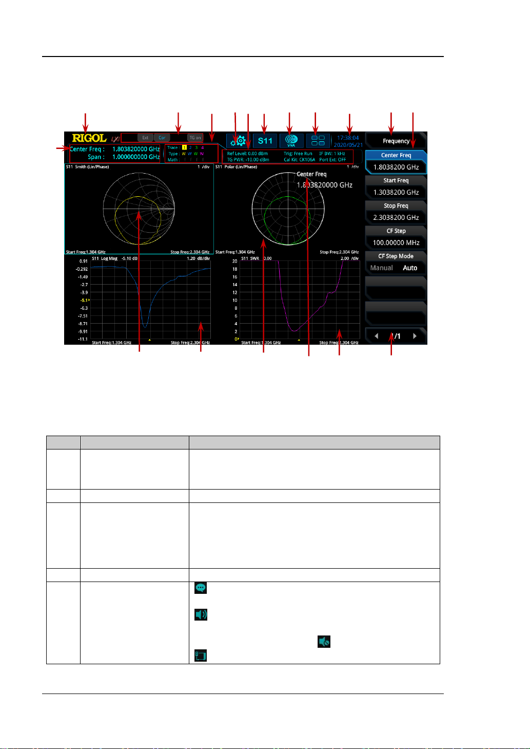
User Interface
Figure 1-1 User Interface (VNA)
Table 1-1 User Interface Icons
No.
Name
Description
1
Measurement result
Displays the current measurement results for the
marker (when no marker exists, the measurement
results display frequency/span value).
2
RIGOL
Indicates the company logo.
3
System status
Rmt: indicates remote operation.
Ext: indicates the external reference.
Cor
[1]
: indicates the calibration status.
TG on: indicates that the tracking generator has
been enabled.
4
Trace indicator
[2]
Displays information about the trace.
5
Information setting
: indicates messages, such as the prompt
messages, alarm messages, and error messages.
: indicates the speaker. You can tune it up and
down to increase and decrease the speaker
volume, or set it to mute .
: indicates the network settings. You can
2 3 4 5 6 7 8 9 10
11 12
1
18 17 16 15 14 13

Chapter 1 Quick Start RIGOL
VNA User Guide 1-3
configure network parameters.
: unlocks the front panel keys; : locks the
front panel keys.
: unlocks the touch screen; : locks the touch
screen.
: indicates that no USB storage device is
inserted; : indicates that a USB storage device
has been inserted.
6
Measurement bar
Displays measurement settings.
7
Measurement
function
Displays the currently selected measurement
function.
8
Working mode
Displays the currently selected working mode.
9
Function keypad
Clicks the keypad to display the function keypad
interface.
10
Time
Displays the system time.
11
Menu title
Displays the currently selected menu name.
12
Menu item
Displays the menu item of the current function.
13
Menu page
Shows the current page and the total number of
pages for the menu.
14
Trace 4 window
Displays the waveform or data of Trace 4.
15
Active function area
Displays the current parameter and its value.
16
Trace 3 window
Displays the waveform or data of Trace 3.
17
Trace 2 window
Displays the waveform or data of Trace 2.
18
Trace 1 window
Displays the waveform or data of Trace 1.
Note
[1]
: The definition for the calibration status is shown below:
⚫ --- (in gray): no user calibration data is available.
⚫ Cor (in blue): user calibration data are normal.
⚫ C! (in blue): the system is performing calibration operation.
⚫ C? (in blue): re-calibration is required.
Remarks: When the calibration status shows "C?", it indicates that the current settings
for sweep frequency range, sweep points, power level, IF BW, and other parameters are
different from the values set for performing the calibration, users are required to restart
to perform the calibration under the current configurations.
Note
[2]
: The display of the trace indicator is shown in the following figure:
⚫ The first line displays the trace number. The color of the number is the same as that of
the trace.
⚫ The second line displays the trace type, including W (Clear/Write), A (Trace Average), M
(Maximum Hold), and m (Minimum Hold). The letters with different colors and in
different forms show different meanings.
— The letter in blue indicates that the trace is updating.
— The letter in gray indicates that the trace is not updated.
— The letter with strikethrough and in gray color indicates that the trace will neither
be updated nor displayed.
Trace Number
Trace Type
Trace Math Function

RIGOL Chapter 1 Quick Start
1-4 VNA User Guide
— The letter with strikethrough and in blue color indicates that the trace is updating
but not displayed. It is useful in trace math operation.
⚫ The third line displays the enabling or disabling status of the math operation function of
each trace. If the letter in this line is grayed out, it indicates that the math operation is
disabled. If the letter is indicated as the same color as that of the specified trace, it
indicates that the math operation of this trace is enabled.

Chapter 1 Quick Start RIGOL
VNA User Guide 1-5
Mode Setting
Mode
RSA provides five working modes: GPSA, RTSA, VSA (option), EMI (option), and VNA.
Press Mode or to select the working mode. You can also tap the function keypad to
select the desired mode.
Note: In different working modes, the functions of the keys on the front panel may
be different. Press Help to display the help information of the current working mode.
If you need help information for other modes, exit the help interface first. Then
select the desired working mode and obtain the corresponding help information.
1. GPSA
GPSA adopts two analysis methods: swept and FFT. GPSA can not only carry out
frequency domain analysis, but also time domain (zero span) analysis.
Select GPSA. In this working mode, press Meas to select multiple
measurements. For details, refer to Chapter 2 of
RSA5000 User Guide
or
RSA3000 User Guide.
2. RTSA
RTSA provides the analysis function for the real-time signal, which can capture
the complex signal seamlessly.
Select RTSA. In this working mode, you can also press Meas to select multiple
measurements. For details, refer to Chapter 3 of
RSA5000 User Guide
or
RSA3000 User Guide.
3. VSA
VSA mode provides the standard vector signal analysis measurement function. If
you need this function, please purchase this option (order No. RSA5000-VSA) to
install it. For installation methods, refer to "Install the Option".
4. EMI
EMI mode provides the EMI pre-compatibility measurement function. If you
need this function, please purchase this option (order No. RSA5000-EMI/
RSA3000-EMI) to install it. For installation methods, refer to "Install the
Option".
5. VNA
VNA mode provides the vector network analyzer function. It provides S11, S21,
and DTF measurements. In this working mode, you can press Meas to select
the desired measurement.

RIGOL Chapter 1 Quick Start
1-6 VNA User Guide
Mode Setup
In VNA mode, the Mode Setup menu is grayed out and disabled. The menu items
under Mode Setup are not available.

Chapter 1 Quick Start RIGOL
VNA User Guide 1-7
Install the Option
RSA series provides various options (for option information, refer to "Appendix") to
expand the function of the spectrum analyzer. If you need to purchase the option,
please contact RIGOL sales representative. After you have purchased the option
successfully, you will get the corresponding key. Then perform the following
operations to install the option.
1. Acquire the License of the Option
⚫ Log in to the RIGOL official website (www.rigol.com), click License
Activation to enter the "Registered product license code" interface.
⚫ Input the correct key, serial number (press System → About System →
System Info to acquire the serial number of the instrument), and
verification code. Click Generate to acquire the option license. In the
license generation interface, click Download to download and save the
license file to the PC.
2. Install the Option
You can install the option via the following 2 methods.
1) Install the option by reading the license file from the USB storage device
⚫ Copy the saved option license file to the root directory of the USB
storage device.
⚫ Power on the instrument and insert the USB storage device. Press File
to enter the file operation menu interface.
⚫ Press File Explorer, and then the file manager interface is displayed.
In the interface, find the directory of the USB storage device. Then
select the desired option license file (suffixed with ".lic"). Press Import
License to import the activation code and complete the reading of the
option installation file.
2) Install the option by sending SCPI Commands
⚫ Log in to RIGOL official website (www.rigol.com) to download the
software Ultra Sigma. Then install it according to the installation
wizard.
⚫ Use the USB cable to connect the rear-panel USB DEVICE interface of
RSA series to the USB HOST interface of the PC.
⚫ Run Ultra Sigma. Search the resource and right-click the resource
name. In the displayed menu, select "SCPI Panel Control". Input the
following option installation command in the displayed SCPI control
panel: :SYSTem:LKEY <option info>@<license info>. Wherein,
<option info> indicates the option order No., and <license info>
indicates the option license code.
For example, the following command is used to install the option
RSA5000-PA.

RIGOL Chapter 1 Quick Start
1-8 VNA User Guide
:SYSTem:LKEY
RSA5000-PA@8AD12B8EBC5DF492D1D4289B7CBA5B6150BF6F5D752
D645C36D74530B05F39B49C461B23A50D6C94A34E06782AC4380070
B0D1A86BA84E02768391FFD70C2103

Chapter 2 Functions of the Front Panel RIGOL
VNA User Guide 2-1
Chapter 2 Functions of the Front Panel
This chapter describes in detail the front-panel function keys of RSA series and their
associated menu functions in VNA mode.
Contents in this chapter:
◼ Basic Settings
◼ Sweep and Function Settings
◼ Measurement Settings
◼ Marker Setup
◼ Input/Output
◼ Shortcut Key
◼ System Function

RIGOL Chapter 2 Functions of the Front Panel
2-2 VNA User Guide
Basic Settings
FREQ
Sets the frequency parameters of the analyzer. Press FREQ on the front panel to
enter the frequency setting menu. You can also tap the function keypad at the top of
the screen to select FREQ. The analyzer sweeps within a specified frequency range
and restarts sweeping every time the frequency parameters are modified.
The frequency range of a channel can be expressed by either of two groups of
parameters: Start Frequency/Stop Frequency (
start
f
/
stop
f
); or Center
Frequency/Span (
center
f
/
span
f
). If any of the four parameters is changed, the other
three parameters will make adjustment automatically to ensure the coupling
relationship among them:
2)(
startstopcenter
fff +=
(2-1)
startstopspan
fff −=
(2-2)
In this menu, Center Frequency is, by default, selected.
Center Freq
Sets the center frequency of the current channel.
Remarks:
⚫ When you modify the center frequency, the start and stop frequency will be
modified automatically if the span remains to be unchanged.
⚫ Modifying the center frequency indicates that the frequency is changed along
the current channel horizontally, and the adjustable range should be within the
frequency range specified in the technical specifications of the analyzer.
Table 2-1 Center Frequency
Parameter
Remarks
Default
(Fmax
[1]
- 10 MHz)/2
Range
(100 kHz + 5 Hz ) to (Fmax – 5 Hz)
Unit
GHz, MHz, kHz, Hz
Knob Step
step = span/200, Min = 1 Hz
Left/Right Arrow Key Step
Up/Down Arrow Key Step
CF step
Note
[1]
: The maximum measurement frequency Fmax is determined by the instrument model. For
RSA5065N, Fmax is 6.5 GHz; for RSA5032N, Fmax is 3.2 GHz; for RSA3045N, Fmax is 4.5 GHz; for
RSA3030N, Fmax is 3 GHz; for RSA3015N, Fmax is 1.5 GHz.

Chapter 2 Functions of the Front Panel RIGOL
VNA User Guide 2-3
Start Freq
Sets the start frequency of the current frequency channel.
Remarks:
When you modify the start frequency, the span and center frequency will be
changed.
Table 2-2 Start Frequency
Parameter
Remarks
Default
10 MHz
Range
100 kHz to (Fmax – 10 Hz)
Unit
GHz, MHz, kHz, Hz
Knob Step
step = span/200, Min = 1 Hz
Left/Right Arrow Key Step
Up/Down Arrow Key Step
CF step
The recommended value for the start frequency is determined by IF BW. When you
select a value for IF BW, the system will automatically test the start frequency.
⚫ If the start frequency detected is smaller than the recommended start frequency
value, the recommended start frequency prevails.
⚫ If the start frequency detected is greater than the recommended start frequency
value, the system will take your current setting as the start frequency.
The following table shows the relationship between the recommended value and the
IF BW for different measurement items.
Table 2-3 Relationship between Recommended Start Frequency and IF BW
IF BW
S11 Start Freq
S21 Start Freq
DTF Start Freq
1 kHz
10 MHz
100 kHz
1 MHz
3 kHz
10 MHz
100 kHz
2 MHz
10 kHz
10 MHz
100 kHz
5 MHz
30 kHz
10 MHz
100 kHz
10 MHz
100 kHz
20 MHz
100 kHz
20 MHz
300 kHz
50 MHz
100 kHz
50 MHz
1 MHz
70 MHz
300 kHz
70 MHz
3 MHz
100 MHz
1 MHz
100 MHz
10 MHz
200 MHz
2 MHz
200 MHz
Remarks:
⚫ You can manually set the start frequency to be smaller than the recommended.
⚫ If the start frequency is set too small, the test accuracy will be affected.

RIGOL Chapter 2 Functions of the Front Panel
2-4 VNA User Guide
Stop Freq
Sets the stop frequency of the current frequency channel.
Remarks:
When you modify the stop frequency, the center frequency and start frequency will
be modified automatically if the span remains to be unchanged.
Table 2-4 Stop Frequency
Parameter
Remarks
Default
Fmax
Range
(100 kHz + 10 Hz) to Fmax
Unit
GHz, MHz, kHz, Hz
Knob Step
step = span/200, Min = 1 Hz
Left/Right Arrow Key Step
Up/Down Arrow Key Step
CF step
CF Step
Changes the step size for the center frequency. Changing the center frequency by a
constant step-size value switches the channel to be measured continuously.
Remarks:
Set a proper CF step value, and then select the center frequency. Use the Up/Down
arrow key to switch the measurement channel at a fixed step size. Thus, the
instrument can sweep the adjacent channels manually.
Table 2-5 CF Step
Parameter
Remarks
Default
Fspan/10
Range
-Fmax to Fmax
Unit
GHz, MHz, kHz, Hz
Knob Step
step = span/200, Min = 1 Hz
Left/Right Arrow Key Step
Up/Down Arrow Key Step
at 1-2-5 step
CF Step Mode
The CF step mode consists of "Manual" and "Auto". By default, it is Auto.

Chapter 2 Functions of the Front Panel RIGOL
VNA User Guide 2-5
Remarks:
⚫ In Auto mode, the CF step is 1/10 of the span.
⚫ In Manual mode, you can use the numeric keys to set the step size.

RIGOL Chapter 2 Functions of the Front Panel
2-6 VNA User Guide
SPAN
Sets the frequency range of the current channel. Press SPAN to enter the span
setting menu. You can also tap the function keypad at the top of the screen to select
SPAN.
Changing this parameter will change the frequency parameters, and after the span is
changed, the sweep restarts.
Span
Sets the frequency range of the current channel.
Remarks:
⚫ When you modify the span, the start and stop frequency will be modified
automatically if the center frequency remains to be unchanged.
⚫ When the span is set to a maximum value, the analyzer enters full span mode.
Table 2-6 Span
Parameter
Remarks
Default
Fmax – 10 MHz
Range
[1]
10 Hz to (Fmax - 100 kHz)
Unit
GHz, MHz, kHz, Hz
Knob Step
step = span/200, Min = 2 Hz
Left/Right Arrow Key Step
Up/Down Arrow Key Step
at 1-2-5 step
Note
[1]
: If RSA3015N, RSA3030N, and RSA3045N have not been installed with the RSA3000-BW1
option, then the frequency range of span is from 100 Hz to (Fmax – 100 kHz).
Last Span
Sets the span to the previous span setting.
Full Span
Sets the maximum span.
Remarks:
The default value of full span is (Fmax – 100 kHz).

Chapter 2 Functions of the Front Panel RIGOL
VNA User Guide 2-7
AMPT
Sets the amplitude parameters of the analyzer. Press AMPT on the front panel to
enter the amplitude setting menu. You can also tap the function keypad at the top of
the screen to select AMPT.
You can modify these parameters to make the signals under test easy for you to
observe.
Ref Value
Sets the reference value of the selected trace to adjust the vertical position of the
trace on the screen.
The reference value of each trace format is shown in the following table.
Table 2-7 Reference Value
Trace Format
Default
Range
Unit
Log Mag
0
-500G to 500G
dB
Lin Mag
0
-500G to 500G
N/A
Phase
0
-500G to 500G
degree (°)
Group Delay
0
-500G to 500G
ns
Real
0
-500G to 500G
N/A
Imaginary
0
-500G to 500G
N/A
SWR
1.0
-500G to 500G
N/A
Expand Phase
0
-500G to 500G
degree (°)
Positive Phase
180
-500G to 500G
degree (°)
Return Loss(DTF)
0
-500G to 500G
dB
Log Mag(DTF)
-100
-500G to 500G
dB
Lin Mag(DTF)
0
-500G to 500G
N/A
Remarks:
When the format is "Smith" or "Polar", the reference value is unavailable.
Ref Position
Sets the reference position to adjust the vertical position of the currently selected
trace in the screen.
When it is set to 5, the reference position is located in the middle of the graticule;
when set to 0, it is at the bottom of the graticule; when set to 10, it is located at the
top of the graticule.
 Loading...