


User Guide
RSA3000E Series Real-time
Spectrum Analyzer
Aug. 2019
RIGOL (SUZHOU) TECHNOLOGIES INC.


RIGOL
Guaranty and Declaration
Copyright
© 2019 RIGOL (SUZHOU) TECHNOLOGIES INC. All Rights Reserved.
Trademark Information
RIGOL is a registered trademark of RIGOL (SUZHOU) TECHNOLOGIES INC.
Publication Number
UGD24100-1110
Software Version
00.01.00
Software upgrade might change or add product features. Please acquire the latest
version of the manual from RIGOL we bsite or contact RIGOL to upgrade the
software.
Notices
RIGOL produ cts are cov ered by P.R.C. and f oreign pa tents, issue d and pendin g.
RIGOL reserves the right to modify or change parts of or all the specifications
and pricing policies at the company’s sole decision.
Information in this publication replaces all previously released materials.
Information in this publication is subject to change without notice.
RIGOL shall not be liable for either incidental or consequential losses in
connection with the furnishing, use, or performance of this manual, as well as
any information contained.
Any part of th is d ocu ment is f orbi dden to be c opie d, ph oto copie d, o r rea r ran ged
without prior written approval of RIGOL.
Product Certification
RIGOL guarantees that this product conforms to the national and industrial
standards in China as well as the ISO9001:2015 standard and the ISO14001:2015
standard. Other international standard conformance certifications are in progress.
Contact Us
If you have any problem or requirement when using our products or this manual,
please contact RIGOL.
E-mail: service@rigol.com
Website: www.rigol.com
RSA3000 User Guide I

RIGOL
Safety Requirement
General Safety Summary
Please review the following safety pre cautio ns ca refully before putting the
instrument into operation so as to avoid any personal injury or damage to the
instrument and any product connected to it. To prevent potential hazards, please
follow the instructions specified in this manual to use the instrument properly.
Use Proper Power Cord.
Only the exclusive power cord designed for the instrument and authorized for use
within the local country could be used.
Ground the Instrument.
The instrument is grounded th rou gh t he Protective Earth lead of the power cord. To
avoid electric shock, connect the earth terminal of the power cord to the Protective
Earth terminal before connecting any input or output terminals.
Connect the Probe Correctly.
If a probe is used, the probe ground lead must be connected to earth ground. Do not
connect the ground lead to high voltage. Impr oper w a y of conne ction coul d r esult in
dangerous voltages being present on the connectors, controls or other surfaces of
the oscilloscope and probes, which will cause potential hazards for operators.
Observe All Terminal Ratings.
To avoid fire or shock hazard, observe all r atings an d markers on the instrume nt and
check your manual for more information about ratings before connecting the
instrument.
Use Proper Overvoltage Protection.
Ensure that no over voltage (su ch as that caused by a bolt of lightning) can rea ch the
product. Otherwise, the operator might be exposed to the danger of an electric
shock.
Do Not Operate Without Covers.
Do not operate the instrument with covers or panels removed.
Do Not Insert Objects Into the Air Outlet.
Do not insert objects into the air outlet, as doing so may cause damage to the
instrument.
Use Proper Fuse.
Please use the specified fuses.
II RSA3000E User Guide

RIGOL
Avoid Circuit or Wire Exposure.
Do not touch exposed junctions and components when the unit is powered on.
Do Not Operate With Suspected Failures.
If you suspect that any damage may occur to the instrument, have it inspected by
RIGOL authorized personnel before further operations. Any mainte nance,
adjustment or replacement especially to circuits or accessories must be performed
by RIGOL authorized personnel.
Provide Adequate Ventilation.
Inadequate ventilation may cause an increase of temperature in the instrument,
which would cause damage to the instrument. So please keep the instrument well
ventilated and inspect the air outlet and the fan regularly.
Do Not Operate in Wet Conditions.
To avoid short circuit inside the instrument or electric shock, never operate the
instrument in a humid environment.
Do Not Operate in an Explosive Atmosphere.
To avoid personal injuries or damage to the instrument, never operate the
instrument in an explosive atmosphere.
Keep Product Surfaces Clean and Dry.
T o a void dust or moisture from af fecting the pe rformance of the inst rument, keep th e
surfaces of the instrument clean and dry.
Prevent Ele c tr o static Imp a ct.
Operate the instrume nt i n an ele ctr ostatic dischar ge protectiv e e nvi ron ment to a void
damage induced by static discharges. Always ground both the internal and external
conductors of cables to relea s e sta t i c befo re making connections.
Use the Battery Properly.
Do not expose the battery (if available) to high temperature or fire. Keep it out of the
reach of children. Improper change of a battery (lithium battery) may cause an
explosion. Use the RIGOL specified battery only.
Handle with Caution.
Please handle with care during transportation to avoid damage to keys, knobs,
interfaces, and other parts on the panels.
RSA3000E User Guide III
RIGOL
WARNING
avoided, will result in serious injury or death.
CAUTION
avoided, could result in damage to the product or loss of important data.
DANGER
It calls attention to an operation, if not correctly performed, could
result in injury or hazard immediately.
WARNING
It calls attention to an operation, if not correctly performed, could
result in potential injury or hazard.
CAUTION
It calls attention to an operation, if not correctly performed, could
product.
Hazardous
Voltage
Safety Warning
Protective Earth
Terminal
Chassis Ground
Test Ground
Safety Notices and Symbols
Safety Notic e s in this Manua l:
Indicates a potentially hazardous situation or practice which, if not
Indicates a potentially hazardous situation or practice which, if not
Safety Terms on the Product:
result in damage to the product or other devices connected to the
Safety Symbols on the Product:
IV RSA3000E User Guide
RIGOL
CAUTION
WARNING
supply.
Care and Cleaning
Care
Do not store or leave the instrument where it may be exposed to direct sunlight for
long periods of time.
Cleaning
Clean the instrument regularly according to its operating conditions.
1. Disconnect the instrument from all power sources.
2. Clean the external surfaces of the instrument with a soft cloth dampened with
mild detergent or water. A void having an y water or other obje cts into the chassis
via the heat dissipation hole. When cleaning the LCD, take care to av oid
scarifying it.
To avoid damage to the instrument, do not expose it to caustic liquids.
To avoid short-circuit resulting fr om moisture or personal injuries, ensure
that the instrument is completely dry before connecting it to the power
Environmental Consideratio ns
The following symbol indicates that this product complies with the WEEE Directive
2002/96/EC.
Product End-of-Life Handling
The equipment may contain substances that could b e harmf ul t o the en vi ronment or
human health. To avoid the release of such substances into the environment and
avoid harm to human health, we recommend you to recycle this product
appropriately to ensure that most materials are reused or recycled properly. Please
contact your local authorities for disposal or recycling information.
You can click on the following link
http://www.rigol.com/Files/RIGOL_RoHS2.0&WEEE.pdf to download the latest
version of the RoHS&WEEE certification file.
RSA3000E User Guide V

RIGOL
RSA3000E Series Overview
RSA3000E series is a new generation of cost-efficient real-time spectrum analyzer
with high performance. With superb performance specifications and the clear user
interface, the RSA3000E series allows you to operate it through various ways, such
as pressing keys on the front panel, using the touch screen, connecting the mouse
and the keyboard. Remote communic a ti o n interfaces are also available. The
instrument can be widely used in education science, corporate R&D, industrial
production, and other fields.
Main Features:
Ultra-Real technology
Frequency: up to 3 GHz
Displayed average noise level (DANL): <-161 dBm (typical)
Phase noise: <-102 dBc/Hz (typical)
Level measurement uncertainty: <1.0 dB
3 GHz tracking generator
Min. RBW 1 Hz
EMI measurement application software (option)
Various advanced measurement functions
Multiple measurement modes
Up to 10 MHz real-time analysis bandwidth
Multiple trigger modes and trigger masks
Density, Spectrogram, and oth e r display modes
PC software options
10.1'' capacitive multi-touch screen; supporting touch gestures
USB, LAN, HDMI and other communication and display interfaces
VI RSA3000E User Guide

RIGOL
Document Overview
Topics in this manual:
Chapter 1 Quick Start
This chapter introduces the front/rear panel and user interface as well as
announcements during first use of the analyzer.
Chapter 2 Functions of the Front Panel o f GPSA
This chapter gives detailed function descriptions of the GPSA's front panel keys and
the associated menu keys.
Chapter 3 Functions of the Front Panel of RTSA
This chapter gives detailed function descriptions of the RTSA's front panel key s .
Chapter 4 Functions of the Front Panel of EMI
This chapter gives detailed function descriptions of the EMI's front panel keys.
Chapter 5 Functions of the Front Panel of VSA
This chapter gives detailed function descriptions of the VSA's front panel keys.
Chapter 6 Remote Control
This chapter shows how to control the analyzer in remote mode.
Chapter 7 Troubleshooting
This chapter lists the troubleshooting information and messages that may appear
during the use of the analyzer.
Chapter 8 Appendix
This chapter lists the options and accessories that can be ordered along with your
analyzer as well as the service and support information.
RSA3000E User Guide VII
RIGOL
Model
Frequency Range
Tracking Generator
RSA3030E
9 kHz to 3 GHz
None
RSA3015E
9 kHz to 1.5 GHz
None
RSA3030E-TG
9 kHz to 3 GHz
3 GHz
RSA3015E-TG
9 kHz to 1.5 GHz
1.5 GHz
Format Conventions in this Manual:
1. Keys:
The keys on the front panel are usually denoted by the format of "Key Name
(Bold) + Text Box". For example, FREQ denotes the FREQ key.
2. Menu Keys:
The menu softkeys are usually denoted by the format of "Menu Word (Bold) +
Character Shading". For example, Center Freq denotes the center frequency
menu item under the FREQ function key.
3. Connectors:
The connectors on the front or rear panel are usually denoted by the format of
"Connector Name (Bol d) + Squ are Br ackets (Bold)". For example , [Gen Output
50Ω].
4. Operation Procedures:
"" represents the next step of operation. F or example, FREQ Center Freq
indicates pressing FREQ on the front panel and the n p ressing t he menu s oftkey
Center Freq.
Content Conventions in this Manual:
The RSA3000E series spectrum analyzer includes the following models. This manual
takes RSA3030E-TG as an example.
User Manuals of this Product:
Quick Guide, User Guide, Programming Guide, Data Sheet, etc. For the desired
manual, please download it from www.rigol.com.
VIII RSA3000E User Guide

Contents RIGOL
Contents
Guaranty and Declaration ......................................................................... I
Safety Requirement ................................................................................ II
General Safety Summary ........................................................................... II
Safety Not ices and Symbol s ...................................................................... IV
Care and Cleaning .................................................................................... V
Environmental Considerations .................................................................... V
RSA3000E Series Overview .................................................................... VI
Document Overview .............................................................................. VII
Chapter 1 Quick Start ......................................................................... 1-1
General Inspection ................................................................................ 1-2
Appearance and Dimensions ................................................................... 1-3
To Prepare for Use ................................................................................. 1-4
To Adjust the Supporting Legs .......................................................... 1-4
To Connect to AC Pow e r .................................................................. 1-5
Turn-on Checkout ........................................................................... 1-5
Self-calibration ................................................................................ 1-5
To Set the System Language ............................................................ 1-6
Front Panel ........................................................................................... 1-7
Function Keys on the Front Pane l ..................................................... 1-8
Utility Function Keys on the Front Panel ........................................... 1-10
Front Panel Key Backlight ............................................................... 1-11
Front Panel Connector .................................................................... 1-12
To Use the Numeric Keypad ............................................................ 1-14
Rear Panel ........................................................................................... 1-16
User Interface ...................................................................................... 1-18
GPSA Mode User Interface .............................................................. 1-18
RTSA Mode User Interface .............................................................. 1-20
EMI Mode User Int erface ................................................................ 1-23
VSA Mode User Interface ................................................................ 1-26
Mouse/Keyboard/Touch Screen Operation Rule ........................................ 1-28
Mouse Operation Rule .................................................................... 1-28
Keyboard Operation Rule ................................................................ 1-28
Touch Screen Operation Rule .......................................................... 1-29
Menu Operation ................................................................................... 1-31
Parameter Setting................................................................................. 1-33
To Use the Built-in Help System ............................................................. 1-35
Fuse Replacement ................................................................................ 1-36
Mode Setting ....................................................................................... 1-37
Mode ............................................................................................ 1-37
Mode Setup ................................................................................... 1-38
Install the Option ................................................................................. 1-40
RSA3000E User Guide IX

RIGOL Contents
Chapter 2 Functions of the Front Panel of GPSA ................................ 2-1
Basic Settings ........................................................................................ 2-2
FREQ .............................................................................................. 2-2
SPAN .............................................................................................. 2-8
AMPT ............................................................................................. 2-9
Sweep and Function Settings................................................................. 2-14
BW ............................................................................................... 2-14
Sweep .......................................................................................... 2-18
Trigger ......................................................................................... 2-22
Trace ............................................................................................ 2-27
Tracking Generator ........................................................................ 2-33
Measurement Settings .......................................................................... 2-36
Meas ............................................................................................ 2-36
Meas Setup ................................................................................... 2-39
Marker Measu re ment ............................................................................ 2-67
Marker .......................................................................................... 2-67
Marker To ..................................................................................... 2-74
Marker Functi on ............................................................................ 2-76
Peak ............................................................................................. 2-80
Input/Output ....................................................................................... 2-86
Input Impe da nce ........................................................................... 2-86
Ext Gain ....................................................................................... 2-86
Ext Trigger2 .................................................................................. 2-86
Corrections ................................................................................... 2-87
Demod ......................................................................................... 2-88
Demod Setup ................................................................................ 2-88
Shortcut Key ........................................................................................ 2-89
Auto Tune ..................................................................................... 2-89
Preset........................................................................................... 2-92
User ............................................................................................. 2-96
Quick Save .................................................................................... 2-96
Cont ............................................................................................. 2-96
Single ........................................................................................... 2-96
System Fu nction .................................................................................... 2-1
System ........................................................................................... 2-1
File................................................................................................. 2-9
Recall ........................................................................................... 2-13
Save ............................................................................................. 2-15
Chapter 3 Functions of the Front Panel of RTSA ................................. 3-1
Basic Settings ........................................................................................ 3-2
FREQ .............................................................................................. 3-2
SPAN .............................................................................................. 3-2
AMPT ............................................................................................. 3-5
Sweep and Function Settings................................................................... 3-6
BW ................................................................................................. 3-6
X RSA3000E User Guide

Contents RIGOL
Sweep ........................................................................................... 3-8
Trigger .......................................................................................... 3-10
Trace ............................................................................................ 3-16
Measurement Settings .......................................................................... 3-18
Meas ............................................................................................ 3-18
Meas Setup ................................................................................... 3-26
Marker Setup ....................................................................................... 3-33
Marker .......................................................................................... 3-33
Marker To...................................................................................... 3-33
Marker Functi on ............................................................................. 3-33
Peak ............................................................................................. 3-33
Input/Output ....................................................................................... 3-34
Input Impe da nce ........................................................................... 3-34
Ext Gain ........................................................................................ 3-34
Ext Trigger2 .................................................................................. 3-34
Shortcut Key ........................................................................................ 3-35
Auto Tune ..................................................................................... 3-35
Preset ........................................................................................... 3-35
User ............................................................................................. 3-38
Quick Save .................................................................................... 3-39
Cont ............................................................................................. 3-39
Single ........................................................................................... 3-39
System Fu nction .................................................................................... 3-1
System .......................................................................................... 3-1
File ................................................................................................ 3-9
Recall ........................................................................................... 3-13
Save ............................................................................................. 3-15
Chapter 4 Functions of the Front Panel of EMI ................................... 4-1
Basic Settings ....................................................................................... 4-2
FREQ ............................................................................................. 4-2
SPAN ............................................................................................. 4-5
AMPT ............................................................................................. 4-6
Sweep and Function Setting s .................................................................. 4-9
BW ................................................................................................ 4-9
Sweep .......................................................................................... 4-11
Trigger .......................................................................................... 4-13
Trace ............................................................................................ 4-16
Measurement Settings .......................................................................... 4-19
Meas ............................................................................................ 4-19
Meas Setup ................................................................................... 4-19
Marker Measurement ............................................................................ 4-30
Marker .......................................................................................... 4-30
Marker-> ...................................................................................... 4-34
Marker Func .................................................................................. 4-35
Peak ............................................................................................. 4-37
RSA3000E User Guide XI

RIGOL Contents
Input/Output ....................................................................................... 4-40
Input Impe da nce ........................................................................... 4-40
Ext Gain ....................................................................................... 4-40
Ext Trigger2 .................................................................................. 4-40
Corrections ................................................................................... 4-41
Shortcut Key ........................................................................................ 4-43
Auto Tune ..................................................................................... 4-43
Preset........................................................................................... 4-43
User ............................................................................................. 4-46
Quick Save .................................................................................... 4-46
Cont ............................................................................................. 4-46
Single ........................................................................................... 4-46
System Fu nction .................................................................................. 4-47
System ......................................................................................... 4-47
File............................................................................................... 4-56
Recall ........................................................................................... 4-60
Save ............................................................................................. 4-63
Chapter 5 Functions of the Front Panel of VSA ................................... 5-1
Basic Settings ........................................................................................ 5-2
FREQ .............................................................................................. 5-2
SPAN .............................................................................................. 5-5
AMPT ............................................................................................. 5-8
Sweep and Function Setting s................................................................. 5-10
BW ............................................................................................... 5-10
Sweep .......................................................................................... 5-12
Trigger ......................................................................................... 5-13
Trace ............................................................................................ 5-22
Measurement Settings .......................................................................... 5-26
Meas ............................................................................................ 5-26
Meas Setup ................................................................................... 5-27
Marker Measu re ment ............................................................................ 5-35
Marker .......................................................................................... 5-35
Marker-> ...................................................................................... 5-40
Marker Func .................................................................................. 5-42
Peak ............................................................................................. 5-43
Input/Output ....................................................................................... 5-44
Input Z ......................................................................................... 5-44
Ext Gain ....................................................................................... 5-44
Ext Trigger 2 ................................................................................. 5-44
Shortcut Key ........................................................................................ 5-45
Auto Tune ..................................................................................... 5-45
Preset........................................................................................... 5-45
User ............................................................................................. 5-47
Quick Save .................................................................................... 5-47
Cont ............................................................................................. 5-48
XII RSA3000E User Guide

Contents RIGOL
Single ........................................................................................... 5-48
System Fu nction ................................................................................... 5-49
System ......................................................................................... 5-49
File ............................................................................................... 5-56
Recall ........................................................................................... 5-60
Save ............................................................................................. 5-61
Chapter 6 Remote Control .................................................................. 6-1
Remote Control Overview ....................................................................... 6-2
Remote Control via USB ......................................................................... 6-3
Remote Control via LAN ......................................................................... 6-4
Chapter 7 Troubleshooting ................................................................. 7-1
Chapter 8 Appendix ............................................................................ 8-1
Appendix A: RSA3000E Accessories and Option List .................................. 8-1
Append i x B: Warranty ............................................................................ 8-2
Index ....................................................................................................... 1
RSA3000E User Guide XIII


Chapter 1 Quick Start RIGOL
Chapter 1 Quick Start
This chapter gives you a quick review about the appearance and dimensions of the
RSA3000E series, its front and rear panel, user interface, as well as announcements
during first use of the analyzer.
Contents in this chapter:
General Inspection
Appearance and Dimensions
To Prepare for Use
Front Panel
Rear Panel
User Interface
Mouse/Keyboard/Touch Screen Operation Rule
Menu Operation
Parameter Setting
To Use the Built-in Help System
Fuse Replacement
Mode Setting
RSA3000E User Guide 1-1

RIGOL Chapter 1 Quick Start
General Inspection
1. Inspect the packaging
If the packa gi ng has be en da m age d, do n ot dis po se t he da m age d pac ka gin g o r
cushioning materials until the shipment has been check ed for completeness an d
has passed both electrical and mechanical tests.
The consigner or carrier shall be liable for the d amage to the instrument
resulting from shipment. RIGOL would not be responsible for free
maintenance/rework or replacement of the instrument.
2. Inspect the instrument
In case of any mechanical d amage, missing parts, or failure in passing the
electrical and mechanical tests, contact your RIGOL sales representative.
3. Check the accessories
Please check the accessories according to the packing lists. If the ac cessories
are damaged or i n complete, please contact your RIGOL sales representative.
1-2 RSA3000E User Guide
Chapter 1 Quick Start RIGOL
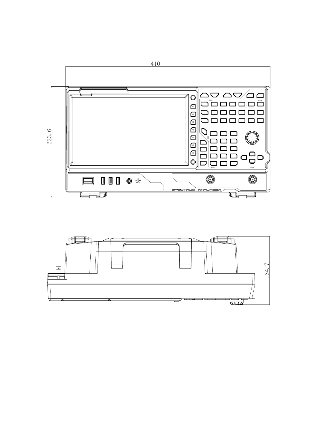
Appearance and Dimensions
Figure 1-1 Front View Unit: mm
Figure 1-2 Vertical View Unit: mm
RSA3000E User Guide 1-3
RIGOL Chapter 1 Quick Start
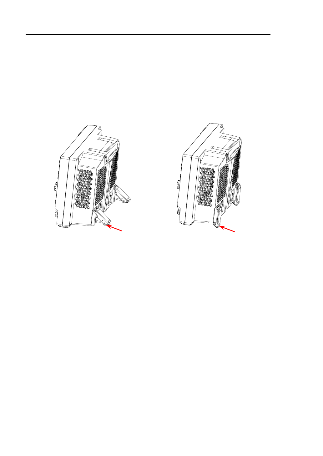
To unfold the
To fold the
To Prepare for Use
To Adjust the Supporting Legs
You c an unfold the supporting legs to use them as stands to tilt the instrument
upwards for easier operation and observation. You can also fold the supporting legs
for easier storage or shipment when the instrument is not in use.
supporting legs
supporting legs
Figure 1-3 To Adjust the Supporting Legs
1-4 RSA3000E User Guide
Chapter 1 Quick Start RIGOL
CAUTION
To Connect to AC Power
Please use the power cor d provided in the accessories to connect the spectrum
analyzer to the AC power sou rce. The AC powe r supply specification of this spectrum
analyzer is 100-240 V, 45-440 Hz. The power consumption of the instru ment cannot
exceed 95 W. When the spectrum analyzer is connected to the AC power source via
the power cord, the instrument automatically adapts to the voltage range, and you
do not need to select the voltage range manually .
To avoid electric shock, ensure that the instrument is correctly grounded.
Turn-on Checkout
After connecting the instrument to the power source properly, press the Power key
on the front panel to start the spectrum analyzer. Then, you will see an initial
splash screen. Following the start-up screen which shows the start-up initialization
process information, the sweep curve is displayed.
Self-calibration
After the instrument starts, execute self-calibration.
Press System Alignment Align Now, and then the instrument will perform
self-calibration with the internal calibration source.
RSA3000E User Guide 1-5

RIGOL Chapter 1 Quick Start
To Set the System Language
RSA3000E series spectrum analyzer supports multiple system languages. You can
press System Language to switch the system language.
1-6 RSA3000E User Guide
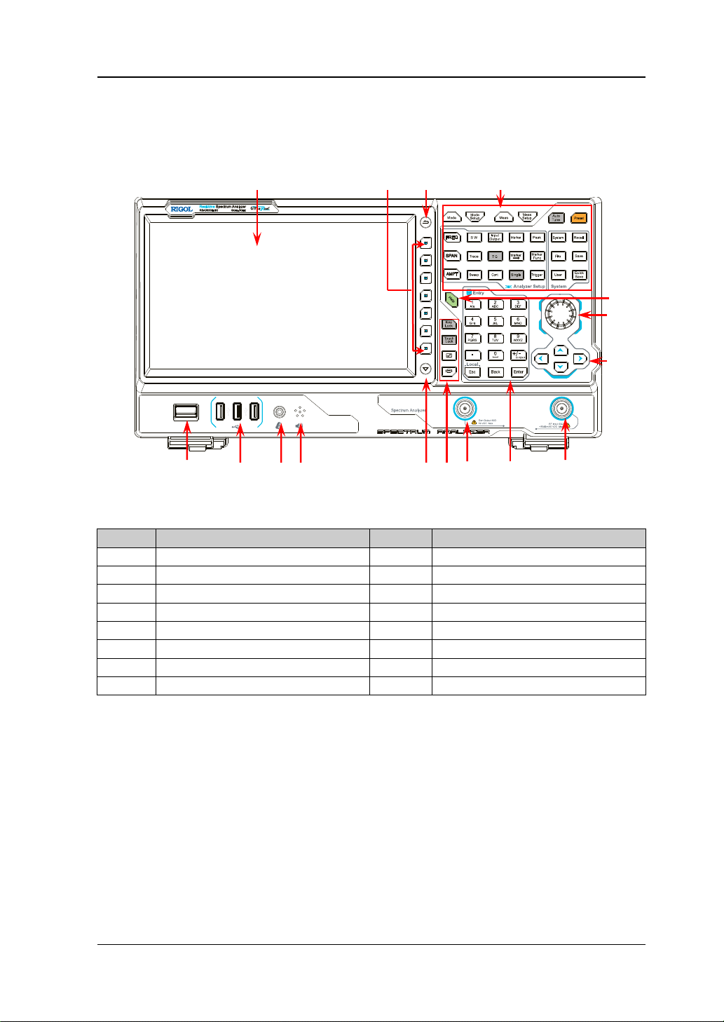
Chapter 1 Quick Start RIGOL
No.
Description
No.
Description
1
LCD
9
Numer ic keypad
2
Menu softkeys
10
Tracking generator output
[1]
3
Back to previous menu item
11
Utility function key area
4
Function key area
12
Page up/down key
5
Help key
13
Speaker
6
Knob
14
Earphone jack
7
Arrow keys
15
USB HOST
8
RF input
16
Power key
1 2 3
16 15 14 13 12 11 10 9 8
5
4
Front Panel
The front panel of RSA3000E is shown in the following figure.
Figure 1-4 Front Panel
Table 1-1 Front P anel Description
6
7
[1]
Note
: This function is only available for RSA3030E-TG/RSA3015E-TG.
RSA3000E User Guide 1-7
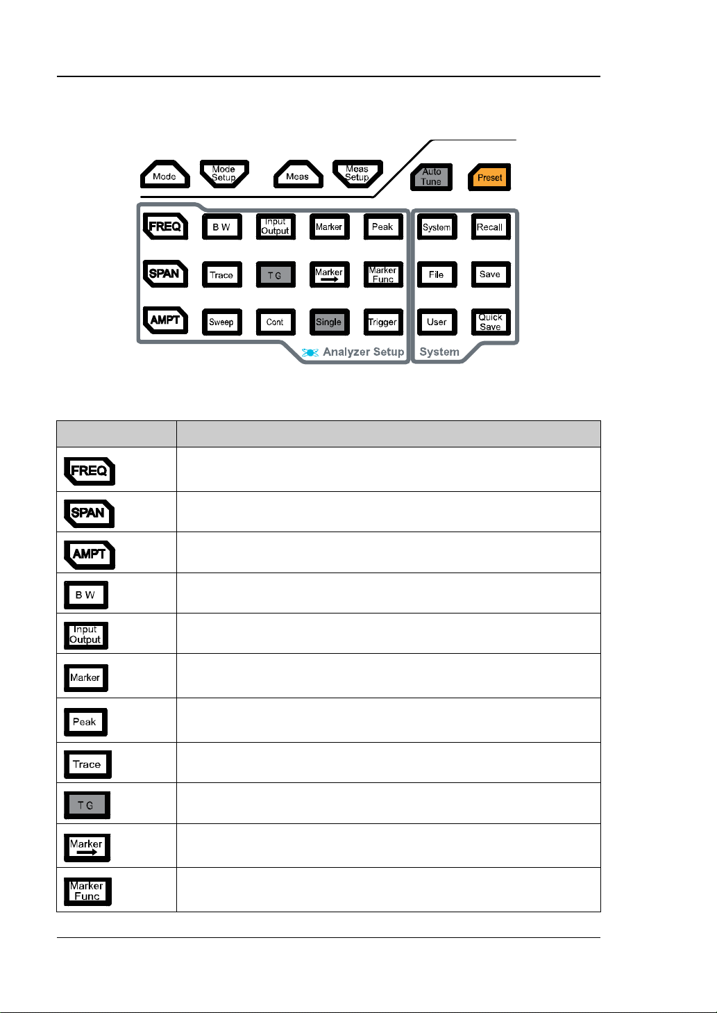
RIGOL Chapter 1 Quick Start
Function Key
Description
and stop frequency; enables the signal tracking function.
trace via marker.
immediately.
value.
marker, N dB bandwidth measurement, and fr equency counter.
Function Keys on the Fron t Panel
Figure 1-5 Function Keys
Table 1-2 Descriptions of Function Keys on the Front Panel
Sets the parameters such as center frequency, start frequency,
Sets the frequency span of the sweep.
Sets the parameters such as reference level, RF attenuator,
scale, and Y-axis unit. Enables preamp.
Sets the parameters such as resolution bandwidth (RBW ) and
video bandwi dt h (VBW).
Sets the parameters suc h as input impedance, external gain,
and External Trigger 2. Selects the RF calibration signal.
Reads the amplitude and frequency of a certain point on the
Opens the peak search menu and searches for peaks
Sets the parameters related to trace.
Sets the parameters related to the tracking generator
[1]
.
Sets other system parameters based on the current marker
Indicates the special functions of the marker, such as noise
1-8 RSA3000E User Guide
Chapter 1 Quick Start RIGOL
Tip:
keypad.
Sets the sweep parameters.
Sets the sweep/measurement mode to be continuous.
Sets the sweep/measurement mode to be single.
Sets the trigger source and its related parameters.
Selects the working mode of the spectrum analyzer.
Sets the parameters for the selected working mode.
Note
Note
Selects and controls the measurement function
Sets the parameters
[2]
for the selected measurement function.
[2]
.
Searches for signals automatically within full frequency range.
Restores the system to factory settings or user-defined state.
Sets the system parameters.
Recalls the files.
Manages the files.
Saves the files.
User-defined shortcut key.
Provides quick save f unction.
[1]
: This function is only available for RSA3030E-TG/RSA3015E-TG.
[2]
: This function is only ava ila b le for the instrument installed with RSA3000E-AMK.
Click the function keypa d icon at the right corner of the LCD or finger-touch it,
and then the function keypad that corresponds to the specified keys on the front
panel appears. At this time, you can operate the instrument with the function
RSA3000E User Guide 1-9
RIGOL Chapter 1 Quick Start
Utility Function Keys on the Front Panel
Table 1-3 Descriptions of Utility Function Keys on the Front Panel
Locks all the keys (exc ept the Power key) on the fr ont panel.
Locks the touch screen of the instrument.
In the multi-window display mode, press this key to select the
specif ied window to zoom it in or out.
In the multi-window display mode, press this key to switch the
window.
1-10 RSA3000E User Guide
Chapter 1 Quick Start RIGOL
Front Panel Key Backlight
The on/off state and the color of the backlights of some keys on the front panel
indicate the working state of the spectrum analyzer. The states are listed below.
1. Power Key
Flash on and off alternativ ely, in breathing state: indicates that the unit is i n
stand-by state.
Constant on: indicates that the instrument is in normal operating state.
2. Auto Tune
When you press the Auto Tune key, it is illuminated. The instrument starts
sweeping within the full frequency range, searches for the sig nal with the
maximum amplitude and moves it to the center of the screen. After the sweep is
completed, the backlight turns off.
3. Tracking Generator
When the tracking generator function is enabled, the TG key is illuminated;
when disabled, the backlight of the TG key is off.
4. Single
When the Single key is illuminated, it indic ates that the sweep/measurement
mode is single.
5. Keypad Locking Key
When the backlight is on, it indicates that all the k eys (except the Power ke y) on
the front panel is locked . Press the key a gain to unlock the f ront panel ke ys, and
then the backlight of the key is off.
6. Touch Screen Locking Key
When the backlight is on, it indicates that the touc h screen of the instrument is
locked. Press the key again to unlock the touch screen, and then the backlight is
off.
RSA3000E User Guide 1-11
RIGOL Chapter 1 Quick Start
USB HOST
Earphone Jack
TG Output
RF Input
Front Panel Connector
Figure 1-6 Front Panel Connector
1. USB HOST
The analyzer can serve as a "master" device to connect to the external USB
device. The USB storage device, mouse, and keyboard can be connected to the
instrument via the interface.
USB Storage Device
Reads the state file, trace+state file, measurement data file, limit line f ile,
and FMT file (in RTSA mode) from the USB storage device; or stores the
current instrument state, tra ce, measu rement data, limit line , or FMT to the
USB storage device; or stores the contents currently displayed on the
screen to the USB storage device in ".jpg", ".bmp", or ".png" format.
Mouse
After the mouse is properly connected to the instrument, you can use it to
click on the screen to perform pa rameter setting and function configuration.
For detail s , refer to descriptions in "Mouse/Keyboard/Touch Screen
Operation Rule".
Keyboard
After the keyboard i s prop erly connected t o the instr ument, you can use t he
shortcut keys on the keypad to perform the same function as what you do
with the front panel keys. For details, refer to descriptions in
"Mouse/Keyboard/Touch Screen Operation Rule".
2. Earphone Jack
Insert the earphone to the jac k to acquire the audio output of the demodulated
signal.
1-12 RSA3000E User Guide
Chapter 1 Quick Start RIGOL
CAUTION
To avoid damaging your hearing, please t urn the volume dow n
putting on the earphone.
CAUTION
cannot exceed +10 dBm when the frequency is lower than 10
should not exceed 50 V.
CAUTION
DC voltage c ompone nt and t he maxi mum con tinuou s powe r of
dBm to avoid damaging the instrument.
to zero first and then gradually turn the volume up after
3. Gen Output 50Ω
The output of the tracking generator can be connected to a receiver through a
cable with an N male co nnector. This function is only available for
RSA3030E-TG/RSA3015E-TG.
To avoid damage to the tracking generator, the reverse power
MHz; the reverse power cannot exceed +20 dBm when the
frequency is greater than 10 MHz. The reverse DC voltage
4. RF Input 50Ω
The input terminal of the signal u nde r tes t. [RF Input 50Ω] can be connected
to the device under test (DUT) via a cable with an N male connector.
For the signal inp ut to the RF input terminal, ensure that the
the AC (RF) signal component do not exceed 50 V and +30
RSA3000E User Guide 1-13
RIGOL Chapter 1 Quick Start
To Use the Numeric Keypad
The numeric keypad is available on the front panel of RSA3000E, as s hown in the
figure below. The numeric keypad supports the Chinese characters, English
uppercase/lowercase letters, numbers, and common symbols (including decimal
point, space, and +/- signs), which are mainly used to edit the file/folder name and
set parameters (refer to "Parameter Setting").
Figure 1-7 Numeric Keypad
The numeric keypad consists of the following parts:
1. Number/Letter
Multiplexing keys for numbers and letters. They are used to dir ectly input
the desired number or letter.
uppercase and lowercase letter in English input. This key is invalid in
Chinese input.
number input and space in Chinese or English input.
2.
Press this key to inp ut a decimal point at the current cursor position in
number input.
This key is invalid in Chinese or English input.
: press this key to input 1 in number input; to switch between
is the multiplexing key for 0 and space. Press this key to inp ut 0 in
1-14 RSA3000E User Guide

Chapter 1 Quick Start RIGOL
3.
The number input mode is , by default , selected f or para meter setting . Press
this key to input the symbol ("+" or "-"). Whe n you pre s s the key for the
fi r s t tim e, the parameter symbol "-" is displayed, and when you press it
again, "+" is displayed.
When you input a file or folder name, press this key repeatedly to switch
among the Chinese input, Eng lish input, and number input.
4.
When editing the parameter, press this key to exit parameter input.
When you edit the filename with the on-screen keyboard, pres s th is key to
hide the on-screen keyboard.
In multi-touch test, single-touch test, and keyboard test state, pre ss this
key to exit the current test state.
When the instrument is in rem ote mode, press this k ey to return to the local
mode.
5.
When editing the parameter, press this key to delete the character to the
left of the cursor.
When editing the file name, press this key to delete the character to the left
of the cursor.
6.
During parameter editing, pressing this key will complete the input and insert a
default unit for the parameter.
RSA3000E User Guide 1-15

13
1 2 3 4
RIGOL Chapter 1 Quick Start
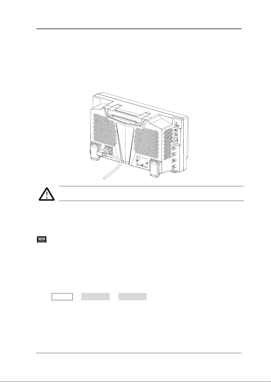
Rear Panel
The rear panel of RSA3000E is shown in the following figure.
Figure 1-8 Rear Panel
1. AC Power Cord Connector
The AC power supply sp ecification of RSA3000E is: 100-240 V; 45-440 Hz.
2. Fuse Holder
You can replace the fuse. The fuse r ating supported by the inst rument is AC 25 0
V, T3.15 A.
3. OCXO (Option)
OCXO (Oven Cont rolled Crystal Oscillat or) c an p rovid e a hi ghly sta ble frequen cy
reference over tem peratu re v ariations. F or order information of the option, ref er
to the datasheet manual. Note: A 40-minute warm-up is required for OCXO to
reach its nominal frequency.
4. Handle
You can rotate the handle upright and make the portable instrument easy to
carry.
5. 10MHz IN
RSA3000E can use the internal or external reference source.
When a 10 MHz external clock signal is received at the [10 MHz IN]
connector, this signal is used as the external ref erence source. At this time,
the status bar of the user interface displays "Ext". When the external
12
11
10
9
8
7
6
5
1-16 RSA3000E User Guide

Chapter 1 Quick Start RIGOL
reference is lost, transfinite, or not connected, the instrument switches to
the internal reference aut omatically . At this time, the icon "Ext" in the status
bar of the user interfac e disappears.
The [10MHz IN] and [10MHz OUT] connectors are usually used to
realize synchronization among multiple instruments.
Note: When you input or d isconnect an external clock signal for the first time,
the network will be reconfigured.
6. 10MHz OUT
RSA3000E can use the internal or external reference source.
When the internal reference source is used, the [10MHz OUT] connector
can output a 10 MHz clock signal generated by the a nalyzer. This signal can
be used to synchronize other instruments.
The [10MHz OUT] and [10MHz IN] connectors are usually used to
realize synchronization among multiple instruments.
7. TRIGGER IN / OU T
Indicates the input and output terminal of Ext Trigger2. You can press
Input Output Ext Trigger2 to set it to be the external trigger input
interface; or use it to synchronize the trigger output interfaces of other test
devices.
8. TRIGGER IN
Indicates the input t erminal of Ext Trigger1. The Ext T rigger1 signal is sent t o the
spectrum analyzer through a BNC cable.
9. LAN
Through this interface, the analyzer can be connected to your loc al network for
remote control. An i ntegrated test ing system can be built quickly , as the analyzer
conforms to LXI Core 2011 Device instrument standards.
10. USB DEVICE
The analyzer can serve as a "slave" device to connect to the e xternal USB device.
The analyzer can be connec ted to the PC through this interface. Then, the
RSA3000E series spectrum analyzer can be controlled remotely through
programm i ng or the PC software.
11. USB HOST
The analyzer can serve as a "master" device to connect to the external USB
device. The USB storage device, the keyboard, and the mouse can be connected
to the instrument via the interface.
12. HDMI
The interface is used to connect to the display, enabling you to clearly observe
the signal under test and its characteristics.
RSA3000E User Guide 1-17

RIGOL Chapter 1 Quick Start
No.
Name
Description
1
Reference level
Displays the reference level value.
2
Measurement result
Displays the current measurement results for the
results display frequency/span v alue) .
3
RIGOL
Indicates th e company logo.
4 System status
Rmt: indicates remote operation.
Uncal: indicates that the measurement has not be
3 4 5 6 7 8 9 10 11 12
13 14
2
1
24 23 22 21 20 19 18 17 16 15
13. IF OUT
Indicates the intermediate frequency signal in the output RF component. Its
center frequency is 430 MHz .
User Interface
GPSA Mode User Interface
The user interface of GPSA mode is shown in the following figure.
Figure 1-9 User Interface (GP SA Mod e )
Table 1-4 User Interface Icons
marker (when n o ma rker exists, the measurement
Ext: indicates the external reference.
1-18 RSA3000E User Guide

Chapter 1 Quick Start RIGOL
calibrated.
been enabled.
5
Trace indica t or
[1]
Displays information abo ut the trace and the
detector.
6
Information setting
: indicates messages, such as the prompt
has been inserted.
7
Measurement bar
Displays measurement settings.
8
Measurement
function
Displays the currently selected measurement
function.
9
Worki ng mode
Displays the currently selected working mode.
10
Clicks the keypad to d isplay the function keypad
interface.
11
Active function area
Displays the current parameter and its value.
12
Time
Displays the system time.
13
Menu title
Displays the currently selected menu name.
14
Menu item
Displays the menu item of the current function.
15
Shows the current page and the total number of
pages for the menu.
16
Sweep time and
points
Indicates the sweep time and the number of
sweep points in swept mode.
17
The frequency range of the current sweep channel
frequency and stop frequency.
18
Trigger level
Indicates video trigger level.
19
Indicates the readout reference and the threshold
criteria for the peak
20
VBW
Indicates video bandwidth.
21
Spectrum line
displ ay area
PA on: indicates that the preamp has been
enabled.
TG on: indicates that the tracking generator has
messages, alarm messages, and error messages.
: indicates the speaker. You can tune it up and
down to increase and decrease the speaker
volume, or set it to mute
.
: indicates the network settings. You can
configure network parameters.
: unlocks the front panel keys; : locks the
front panel keys.
: unlocks the touch screen; : locks the touch
screen.
: indicates that no USB storage device is
inserted;
: indicates that a USB storage device
Function keypad
Menu page
Span or stop
frequency
can be expressed by the combination of center
frequency and span or the combination of start
Display line
Indicates the display area for the spec trum line.
RSA3000E User Guide 1-19

RIGOL Chapter 1 Quick Start
22
RBW
Indicates the resolution bandwidth.
23
The frequency range of the current sweep channel
frequency and stop frequency.
24
Y scale
Indicates the scale indication in the Y axis.
Trace Number
Trace Type
Detector Type
Center or start
frequency
[1]
Note
: The display of the trace indicator is shown in the following figure:
The first line displays the trace number. The color of the number is the same as that of
the trace.
The second line displays the trace type, including W (Clear/Write), A (Average), M
(Maximum Hold), and m (Minimum Hold). The letters with different colors and in
different forms show different meanings.
— The letter in blue indicates that the trace is updating.
— The letter in gray indicates that the trace is not updated.
— The letter with strikethrough and in gray color indicates that the trace will neither
be updated nor displayed.
— The letter with strikethrough and in blue color indicates that the trace is updating
but not displayed. It is useful in trace math operation.
The third line displays the detector type of each trace, including N (Normal), V (Voltage
Average ), P (Positive Pe ak), p (Negative Pea k), S (Sample), R (RMS Aver age), Q (Quasi
Peak, option), and A (Average). If it shows "f", it indicates that it is math operation
trace. The letter in blue in the third line (detector type) indicates that the detector is in
auto state; the letter in white indicates that it is in manual state.
can be expressed by the combination of center
frequency and span or the combination of start
RTSA Mode User Interface
The user interface of RTSA mode is shown in the following figure.
1-20 RSA3000E User Guide

Chapter 1 Quick Start RIGOL
No.
Name
Description
1
Reference level
Displays the reference level value.
2
Measurement result
Displays the current measurement results for the
marker (when n o ma rker exists, the measurement
results display frequency/span v alue) .
3
RIGOL
Indicates th e company logo.
4 System status
Rmt: indicates remote operation.
enabled.
5
Trace indica t or
[1]
Displays information abo ut the trace and the
detector.
6
Information setting
: indicates messages, such as the prompt
configure network parameters.
3 4 5 6 7 8 9 10 11 12
13 14
2
16 15
1
Figure 1-10 User Interface (RTSA Mode)
Table 1-5 User Interface Icons
Ext: indicates the external reference.
Uncal: indicates that the measurement has not be
calibrated.
PA on: indicates that the preamp has been
messages, alarm messages, and error messages.
: indicates the speaker. You can tune it up and
down to increase and decrease the speaker
volume, or set it to mute
RSA3000E User Guide 1-21
: indicates the network settings. You can
.

RIGOL Chapter 1 Quick Start
has been inserted.
7
Measurement bar
Displays measurement settings.
8
Measurement
function
Displays the currently selected measurement
function.
9
Worki ng mode
Displays the currently selected working mode.
10
Clicks the keypad to d isplay the function keypad
interface.
11
Active function area
Displays the current parameter and its value.
12
Time
Displays the system time.
13
Menu title
Displays the currently selected menu name.
14
Menu item
Displays the menu item of the current function.
15
Shows the current page and the total number of
pages for the menu.
16
Spectrum display
area
Trace Number
Trace Type
Detector Type
: unlocks the front panel keys; : locks the
front panel keys.
: unlocks the touch screen; : locks the touch
screen.
: indicates that no USB storage devic e is
inserted;
: indicates that a USB storage device
Function keypad
Menu page
Indicates the display area for the sp ectrum.
[1]
Note
: The display of the trace indicator is shown in the following figure:
The first line displays the trace number. The color of the number is the same as that of
the trace.
The second line displays the trace type, including W (Clear/Write), A (Average), M
(Maximum Hold), and m (Minimum Hold). The letters with different colors and in
different forms show different meanings.
— The letter in blue indicates that the trace is updating.
— The letter in gray indicates that the trace is not updated.
— The letter with strikethrough and in gray color indicates that the trace will neither
be updated nor displayed.
— The letter with strikethrough and in blue color indicat es t hat the trace is updating
but not displayed. It is useful in trace math operation.
The third line displays the detector type of each trace, including P (Positive Peak), p
(Negative Peak), S (Sample), and A (Average). If it shows "f", it indicates that it is
math operation trace. The letter in blue in the third line (detector type) indicates that
the detector is in auto state; the letter in white indicates that it is in manual state.
1-22 RSA3000E User Guide

Chapter 1 Quick Start RIGOL
No.
Name
Description
1
Marker
Displays the current measurement results f or the
Span).
2
RIGOL
Company logo.
3
System status
Rmt: indicates remote operation.
CISPR: indicates that the EMC standard.
4
Trace indica t or
[1]
Displays information abo ut the trace and the
detector.
5
Information setting
: indicates the speaker. You can tune it up and
2 3 4 5 6 7 8 9 10 11 12
1
17 16 15 14 13
EMI Mode User Interface
The user interface of EMI mode is shown in the following figure.
Figure 1-11 User Interface (EMI Mode)
Table 1-6 User Interface Icons
measurement
result
marker (when n o ma rker exists, the measurement
results display Frequency( Meter), Mids pan Freq, and
Ext: indicates the external reference.
Uncal: indicates that the m easurement has not be
calibrated.
PA on: indicates that the preamp has been enabled.
: indicates messages, such as the prompt
messages, alarm messages, and error messages.
RSA3000E User Guide 1-23

RIGOL Chapter 1 Quick Start
down to increase and decrease the speaker volume,
inserted.
6
Measurement bar
Displays measurement settings.
7
Measurement
function
Displays the currently selected measurement
function.
8
Worki ng mode
Displays the currently selected working mode.
9
Function keypad
icon
Clicks/Touches the icon to display the function
keypad interface.
10
Time
Displays the system time.
11
Menu title
Displays the currently selected menu name.
12
Menu item
Displays the menu item of the current function.
13
Menu page
number
Displays the current page and the total number of
pages.
14
Meter
mode
: indicates continue; : indicates single.
15
Meter display area
Displays the histogram of the meter and its
parameter informati o n.
16
Trace display ar ea
Displays the scanned spectral trace and the setting
information after the pre-scan is performed.
17
Signal table display
area
Displays the searched sig nal, which corre sp ond to
the marks in the trace.
Trace Number
Trace Type
Detector Type
or set it to mute .
: indicates the network settings. You can
configure netwo rk parameters .
: unlocks the front panel keys; : locks the
front panel keys.
: unlocks the touch screen; : locks th e t ouch
screen.
: indicates that no USB sto ra ge device is inserted;
: indicates that a USB storage device has been
measurement
[1]:
Note
The display of the trace indicator is shown in the following figure:
The first line displays the trace number. The color of the number is the same as that of
the trace. EMI mode only supports 3 traces.
The second line displays the trace type, including W (Clear/Write), A (T race Average), M
(Maximum Hold), and m (Minimum Hold). The letters with different colors and in
different forms show different meanings:
— The letter in blue indicates that the trace is updating.
— The letter in gray indicates that the trace is not updated.
— The letter with strikethrough and in gray color indicates that the trace will neither
be updated nor displayed.
— The letter with strikethroug h and i n blue color indica tes that the trace is updating
1-24 RSA3000E User Guide

Chapter 1 Quick Start RIGOL
but not displayed. It is useful in trace math operation.
The third line displays the detector type of each trace, including P (Positive Peak), p
(Negative Peak), C (CISPR Av erage), R (RMS A verag e), Q (Quasi Pea k), and V (V oltage
Average). The letter in blue in the third line (detector type) indicates that the detector
is in auto state; the letter in white indicates that it is in manual state.
RSA3000E User Guide 1-25
RIGOL Chapter 1 Quick Start
No.
Name
Description
1
Measurement
Displays center frequency and analysis bandwidth.
measurement results for the marker is displayed.)
2
RIGOL
Company logo.
3
System status
Rmt: indicates remote operation.
PA on: indicates that the preamp has been enabled.
4
Trace indica t or
[1]
Displays information abo ut the trace and the RT
trace detector.
5
Information setting
: indicates messages, such as the prompt
down to increase and decrease the speaker volume,
2 3 4 5 6 7 8 9 10
11 12
1
18 17 16 15 14 13
VSA Mode User Interface
The user interface of V SA mode is shown in the following figure.
Figure 1-12 User Interface (VSA Mode)
Table 1-7 User Interface Icons
result
(when the marker is present, the current
Ext: indicates the external reference.
Uncal: indicates that the m easurement has not be
calibrated.
messages, alarm messages, and error messages.
: indicates the speaker. You can tune it up and
1-26 RSA3000E User Guide

Chapter 1 Quick Start RIGOL
: indicates that no USB stor a ge de vice is inse rted ;
inserted.
6
Measurement bar
Displays measurement settings.
7
Measurement
function
Displays the currently selected measurement
function.
8
Worki ng mode
Displays the currently selected working mode.
9
Function keypad
icon
Clicks/Touches the icon to display the function
keypad interface.
10
Time
Displays the system time.
11
Menu title
Displays the currently selected menu name.
12
Menu item
Displays the menu item of the current function.
13
Menu page
number
Displays the current page and the total number of
pages.
14
Trace4 window
Displ ays the wavefor ms or data of Trace4.
15
Active function
area
16
Trace3 window
Displ ays the wavefor ms or data of Trace3.
17
Trace2 window
Displ ays the wavefor ms or data of Trace2.
18
Trace1 window
Displ ays the wavefor ms or data of Trace1.
Trace Number
Trace Type
Detector Type
or set it to mute .
: indicates the network settings. You can
configure network parameters.
: unlocks the front panel keys; : locks the
front panel keys.
: unlocks the touch screen; : locks the touch
screen.
: indicates that a USB storage device has been
Displays the current parameter and its value.
[1]
Note
: The display of the trace indicator is shown in the following figure:
The first line displays the trace number. The color of the number is the same as that of
the trace. VSA mode only supports 4 traces.
The second line displays the corresponding trace type. VSA mode is invalid.
The third line displays the RT trace detector type of each trace. VSA mode is invalid.
RSA3000E User Guide 1-27

RIGOL Chapter 1 Quick Start
Front Panel Key
Keyboard Shortcut Key
[1]
Mode
Alt + o
Mode Setup
[2]
Shift + o
Meas
Alt + e
Meas Setup
[2]
Shift + e
Auto Tune
Ctrl + Alt + a
Preset
Ctrl + Alt + p
FREQ
[2]
Shift + f
SPAN
[2]
Shift + s
AMPT
[2]
Shift + a
BW
[2]
Shift + b
Trace
[2]
Shift + t
Sweep
[2]
Shift + w
Input Output
[2]
Shift + i
TG
[2]
Shift + g
Cont
F11
Marker
[2]
Shift + m
Marker ->
[2]
Shift + k
Single
F12
Peak
[2]
Shift + p
Mouse/Keyboard/Touch Screen Operation Rule
Mouse Operation Rule
Connect the mouse (note that only the left-click operation is supported; the scroll
and right-click operations with the mouse are not supported) to the spectrum
analyzer via the USB HOST interface to perform the following operations:
1. Click to select the menu and window.
2. Press and hold the left mo use button t o drag the data dis played on the g raticul e
or move the slide ba r.
3. Double-click the d ata displayed on the graticule and then the data will be
appeared at the right-corner.
4. Under the Marker function, you can only use the mouse to move a marker, but
unable to add a marker with the mouse.
Keyboard Operation Rule
Connect the keyboard to the spectrum analyzer via the USB HOST interface, and
then use the shortcut keys on the keyboard to perform the same function as what
you do with the fr ont panel keys.
Table 1-8 Matching Relations between the Front Panel Keys and the Keyboard
Shortcut Keys
1-28 RSA3000E User Guide

Chapter 1 Quick Start RIGOL
Marker Func
[2]
Shift + u
Trigger
[2]
Shift + r
System
[2]
Shift + y
File
Ctrl + f
User
Ctrl + u
Recall
Ctrl + r
Save
Ctrl + s
Quick save
Ctrl + Alt + q
Help
Alt + F1
Alt + F2
Alt + F3
Alt + F4
Alt + F5
Page Up
Page Down
11 numeric keys
Numeric keys on the keyboard: 10 numeric
decimal point(.)
+ + - - Esc
Esc
Back
Backspace
Enter
Enter
Arrow keys
key)
7 menu softkeys from top to
bottom
F1 to F7
numbers (1, 2, 3, 4, 5, 6, 7, 8, 9, 0) and a
(Up/Down/Left/Right arrow
[1]
Note
keyboard do not work for t he menu ope ration.
Note
you're not holding down the "Shift" key. If disabled, you have to press down "Shift" and the
specified letter on the keyboard at the same time to input the letter in uppercase. For example, if
you want to execute the "Shift+f" shortcut key operation, you only need to press "f" on the premise
that the Caps Lock key is enabled.
: Except the keyboard shortcut keys mentioned in the above table, all the other keys on the
[2]
: When the Caps Lock key is enabled, every letter you type would be in uppercase, even if
Touch Screen Operation Rule
RSA3000E has a 10.1-inch capacitive multi-touch screen that supports touch
gestures.
1. When operating on the menus other than the Marker menu:
Tap the trace window, then slide left and right to modify the center
frequency; slide up and down to modify the reference level.
RSA3000E User Guide 1-29
↑, ↓, ←, →

RIGOL Chapter 1 Quick Start
Stretch two fingers horizontally in the trace window to d ecrease the span,
and pinch the fingers horizontally to increase the span. Stretc h tw o fingers
in the vertical direction to decrease the Y-axis scale, and pinch the fingers
vertically to increase the Y-axis scale.
2. When operating on the Marker menu:
In the empty space of the scree n tr ace region , pre ss and ho ld the regi on to
add one new mark er.
Tap and hold one marker to drag the marker.
1-30 RSA3000E User Guide

Chapter 1 Quick Start RIGOL
Select the menu and use the numeric keys to modify the
press Enter to complete parameter input.
Press the corresponding menu key to switch between
Press the corresponding menu key to enter the
Press the corresponding menu key to enter the
Press the key to execute the corresponding function.
current marker.
Press the corresponding menu key and modify the
trigger. The analyzer is in Free Run state at present.
Menu Operation
There are 6 types of menus according to their operation modes. Each type of menu
and its operation method are introduced below.
1. Parameter Input
value directly.
2. State Switching
3. Enter Lower-level Menu (with parameter)
For example, to mod ify center frequency, first select
Center Freq, and then input the desired value. Then,
the sub-options.
For example, press Signal Track, and then you can
switch between "On" and "Off" to enable or disable the
signal tracking func tion.
4. Lower-level Menu (without parameter)
5. Direct Execution
6. State Selection
lower-level menu and change the currently selected
option. The parameter typ e in the u pper-level menu w ill
be changed when you retur n to the upper-level menu
again.
For example, pre ss Y Axis Unit to enter the lower-level
menu. Select dBm and then automatically return to the
previous menu automatically. Then, the unit of Y-axis
will be changed to dBm.
lower-level menu.
For example, press Peak Config to ente r the
lower-level menu directly.
For example, press Mkr->CF to set the center
frequency of the analyzer to the frequency of the
parameters, and then go b ack to the previous menu.
For example, press Source Free Run to select free
RSA3000E User Guide 1-31

RIGOL Chapter 1 Quick Start
Tip:
use the shortcut keys to pe rform the a bove men u oper ations. F or the matching
Table 1-8.
The above menu operations can be executed by touch gestures or clicking with
the externally connected mouse. Also, you can connect to the keyb oard and
relations between the front panel keys and the keyboard shortcut keys, refer to
1-32 RSA3000E User Guide

Chapter 1 Quick Start RIGOL
Parameter Setting
You can enter the desired parameter value s by using the numeric keys, the knob, or
arrow keys on the front panel. Also, you can set the parameters by using the touch
screen, the externally connected keypad or the mouse. This section takes an
example (set the center frequency to 800 MHz) to describe six methods of parameter
setting.
1. Use the numeric keys
1) Press FREQ Center Freq;
2) Input 800 by using the numeric keys;
3) Select the desired unit (MHz) from the pop-up menu.
2. Use the knob
When the parameter is editable, turn the knob clockwise to increase or
counterclockwise to decrease the parameter value at the specif ied step.
1) Press FREQ Center Freq;
2) Rotate the knob until the parameter is set to the desired value (800 M Hz).
Figure 1-13 Knob
3. Use the arrow keys
When the parameter is editable, use the arrow ke ys to increase or decrease the
parameter value at the specific step. Note that the step sizes for the Up/Down
arrow key and the Left/Right arrow key are different.
1) Press FREQ Center Freq;
2) Press the Up/Down arrow key or the Left/Right arrow key until the
parameter is set to the desired value (800 MHz).
Figure 1-14 Arrow Keys
4. Use the touch screen
1) T ouch the screen to select the function keypad icon
corner. Then, the function keypad is displayed. Touch "FREQ";
2) Click Center Freq;
at the upper-right
RSA3000E User Guide 1-33

RIGOL Chapter 1 Quick Start
3) Then the numeric keypad is displayed. Input 800, and select the desired
unit "MHz".
5. Use the keyboard
1) Press "Shift + f" to open the Frequency menu;
2) Press "F1" to select Center Freq;
3) Input 800 by using the num eric keys;
4) Press "F2" to select the desired unit (MHz) from the pop-up menu.
For the matching relations between the front panel keys and the keyboard
shortcut keys, refer to Table 1-8.
6. Use the mouse
1) Click with the mouse to select the function keypad icon
at the
upper-right corner of the screen. Then, the function keypad is displayed.
Click "FREQ";
2) Click Center Freq;
3) Then the numeric keypad is displayed. Input 800, and select the desired
unit "MHz".
1-34 RSA3000E User Guide

Chapter 1 Quick Start RIGOL
To Use the Built-in Help System
The built-in help system provides information about every function key on the front
panel and every menu softkey.
1. Get the built -in help information
Press Help and a prompt message about how to obtain help inf ormation w ill be
shown on the screen. Then, press t he key that y ou wa nt to know about it s usage,
and then the relevant help information for the key will be shown on the sc reen.
2. Page up/down operation
If the help information is displayed in several pages, you can press the arrow
keys or use the knob to page up and d own the help information.
3. Close the current help information
Press any key on the front panel to close the help information currently
displayed on the screen.
When the help information is displayed on the screen, perform any of the
following operations to close the currently display ed help inf ormation dialo g box:
press Esc;
press the Help key again; or
click OK in the displayed help info rmatio n dialo g box.
4. Get the help information of the menu key
Press Help, and the help inf ormation display window is displaye d on the screen.
Then, press the menu key and the help information of the corresponding menu
item is displayed.
5. Get the help information of any function key
Press Help, and the help inf ormation display window is displaye d on the screen.
Then, press any fun ction k ey and the correspondin g function help inf ormation i s
displayed.
RSA3000E User Guide 1-35

RIGOL Chapter 1 Quick Start
WARNING
turned off, the power source has been cut off, and the fuse to be used
conforms to the fuse rating.
Fuse Holder
Fuse
Fuse Replacement
If you need to replac e the fuse, use only the specified fuse (AC 250V, T3.15A) and
perform the following op erations:
1. Turn off the instrument, cut off the power, and remove the power cord.
2. Use a small straight slotted screwdriver to pry out the fuse holder.
3. Take out the fuse hold er.
4. Replace the old fuse with a spec ified fuse.
5. Install the fuse holder.
1-36 RSA3000E User Guide
Figure 1-15 To Replace the Fuse
To avoid electric shock, please ensure that the instrument has been

Chapter 1 Quick Start RIGOL
Mode Setting
Mode
RSA provides four working modes: GPSA, RTSA, VSA (option RSA3000E-ASK/FSK),
and EMI (option RSA3000E-EMI). Press Mode to select the working mode.
Note: In different working modes, the functions of the keys on the front panel may
be different. Press Help to display the help informati on of the cur rent working mo de.
If you need help information for other modes, exit the help interface first. Then
select the desired working mod e and obtain the corresponding help information.
1. GPSA
GPSA adopts two a nalysis methods: swept and FFT. GPSA can not only carry out
frequency domain analysis, but also time domain (zero span) analysis.
Select GPSA. In this working mode, press Meas to select multiple
measurements. For details, refer to Chap t er 2.
2. RTSA
RTSA provides the analysis function for the real-time signal, which can capture
the complex signal seamlessly.
Select RTSA. In this working mode, you can also press Meas to select multiple
measurements. For details, refer to Chap t er 3.
3. VSA
VSA mode provides the standard v ector signal a nalysis measurement function. If
you need this functio n, please purchase this option (order No.
RSA3000E-ASK/FSK), and install it according to instructions in "Inst all the
Option".
4. EMI
EMI mode provides the EMI pre-compatibility measurement function. If you
need this function, please purchase this option (order No. RSA3000E-EMI), and
install it according to instructions in "Inst all the Option".
Note: After purchasing the RSA3000E-EMI option, you do not need to purchas e the
EMC filter and quasi-peak detector kit RSA3000E-EMC, as the RSA3000E-EMI option
contains all the functions of RSA3000E-EMC.
RSA3000E User Guide 1-37

RIGOL Chapter 1 Quick Start
Mode Setup
The Mode Setup menu is used to set parameters that are related to the working
modes.
Open the global parameter setting menu for the selected working mode under
Mode.
Global CF Mode
Turns on or off the global center fr equency. In any working mode, if you enable the
global center frequency mode, then the global center freque ncy will be set to the
center frequency of the current mode. When a different working mode is selected,
the global center frequency will be set to the center frequency of the previous
working mode, that is, the one that is before switching the working mode. If you
change the center frequency in any working mode, then the global center frequency
will change with it.
Global CF
Sets the global center frequency. It is only available when you turn on the global
center frequency.
Mode Preset
Resets the parameters of the current mode to the factory default settings.
EMC Standard (Only Available for EMI Mode)
Sets the EMC standard to "None" or "CISPR".
When "None" is selected, the filter type is set to Gauss. At this point, the filter
bandwidth is -3 dB. The instrument will switch to "CISPR" standard
automatically when "Quasi Peak", "CISPR Average" or "RMS Average" detector is
selected. The filter type is set to EMI. At this point, the filter bandwidth is -6 dB.
When "CISPR" is selected, for Meter 1, the detector is, by default, positive peak;
for Meter 2, the detector is, by default, quasi peak; for Meter 3, the detector is,
by default, CISPR average.
1-38 RSA3000E User Guide

Chapter 1 Quick Start RIGOL
Meters Control (Only Available for EMI Mode)
Sets the parameters of the meter.
1. Meters
1) Select Meter
Specifies the currently selected meter to "Meter1", "Meter2", or "Meter3".
2) Meter
Enables or disables the selected meter.
When enabled, the histogram of the selected meter is displayed in the
meter display area of the user interface, and the corresponding
detector type is selected to perform the measurement.
When disabled, the selected meter is not displayed and the system will
not perform the measurement.
3) Detector
Sets the detector of the selected meter, including "Pos Peak", "Quasi Peak",
"CISPR Average", "RMS Average", "Average(Vol)", and "Neg Peak".
Note: "Quasi Peak", "CISPR Average", "RMS Average", and "Average(Vo l) "
are mutually exclusive. You can at most select two among the thr ee items
("Quasi Peak", "CISPR Average", and "RMS Average").
4) Limit
Sets the limits of the selected meter.
5) Limit State
Enables or disables the limit line of the selected meter.
2. Dwell Time
Sets the dwell time of the meter detector.
3. Peak Hold Time
1) Peak Hold Type
Sets the max hold time type of the meter to "Adjust" or "Infinite".
When "Infinite" is selected, the peak hold line of the sele cted meter will
not be reset. The Adjust Time menu is grayed out and disabled.
When "Adjust" is selected, the peak hold line of the selected meter will
be reset to the current signal value after the set peak hold time. At this
time, you can use the Adjust Time menu to set the peak hold time.
2) Adjust Time
Sets the peak hold time of the meter.
4. Reset Peak Hold
Resets the peak hold lines of all the c urrently enabled meters to the current
RSA3000E User Guide 1-39

RIGOL Chapter 1 Quick Start
signal value.
5. Couple to Signal
Enables or disables the coupling function of the meter and the signal table.
When enabled, the frequenc y of the meter is automatically modified to that of
the selected signal once the selected signal is changed.
6. Couple to Marker
Enables or disables the coupling function of the meter and the current marker.
When enabled, the instrument will set the meter frequency to the current
frequency at the marker.
Install the Option
RSA3000E provides various options (for option information, refer to "RSA3000E
Accessories and Option List") to expan d the f unction of the s pectrum analy zer. If
you need to purchase the option, please contact RIGOL sales representative. After
you have purchased the option successfully, you will obtain a key. Perf o rm the
following operations to install the option.
1. Acquire the license of the option
Log in to the RIGOL official website (www.rigol.com), click License
Activation to enter the "Registered product license code" interface.
Input the correct key, serial number (press System About System
System Info to acquire the serial number of the instrument), and
verification code. Click Generate to acquire the option license. In the
license generation interface, click Download to download and save the
license file to the PC.
2. Install the option
You c an install the option via the following 2 methods.
1) Install the option by reading the license file from the USB storage device
Copy the saved option license file to the root directory of the USB
storage device.
Power on the inst rument and insert the USB sto ra ge device. Press File
to enter the file operation menu interfac e.
Press File Explorer, and then the file manager interface is displayed.
In the interface, find the directory of the USB storage device. Then
select the desired option lic ense file (suffixed with ".lic"). Press
Import License to import the activation code and complete the
reading of the option installation file.
2) Install the option by sending SCPI commands
Log in to RIGOL official website (www.rigol.com) to download the
1-40 RSA3000E User Guide

Chapter 1 Quick Start RIGOL
software Ultra Sigma. Then install it accord ing to the installation
wizard.
Use the USB cable to connect the rear-panel USB DEVICE in te rfa ce of
RSA to the USB HOST interface of the PC.
Run Ultra S ig ma. Searc h the resource and right-click the resource
name. In the displayed menu, select "SCPI Panel Control". Input the
following option installation command in the displayed SCPI control
panel: :SYSTem:LKEY <option info>@<license info>
<option info>
indicates the option or der No., and <license info>
. Wherein,
indicates the option license code.
For example, the following command is used to install the option
RSA3000E-PA.
:SYSTem:LKEY
RSA3000E-PA@8AD12B8EBC5DF492D1D4289B7CBA5B6150BF6F5D75
2D645C36D74530B05F39B49C461B23A50D6C94A34E06782AC438007
0B0D1A86BA84E02768391FFD70C2103
RSA3000E User Guide 1-41


Chapter 2 Functions of the Front Panel of GPSA RIGOL
Chapter 2 Functions of the Front Panel of
GPSA
This chapter describes in d etail the function keys on the front panel and their
associated menu functions in the GPSA mo de of RSA3000E.
Contents in this chapter:
Basic Settings
Sweep and Function Setting s
Measurement Settings
Marker Measu re ment
Input/Output
Shortcut Key
System Fu nction
RSA3000E User Guide 2-1

RIGOL Chapter 2 Functions of the Front Panel of GPSA
start
f
stop
f
center
f
span
f
2)
(
start
stopcenter
ff
f
+=
startstop
span
f
ff
−
=
Basic Settings
FREQ
Sets the frequency parameters of the analyzer. The analyzer sweeps within a
specif ied frequency range and restarts sweeping every time the frequency
parameters are modified.
The frequency range of a channel can be expressed by either of two groups of
/
parameters : Start Frequency/Sto p Frequency (
); or Center
Frequency/Span (
/
). If any of the four parameters is changed, the other
three parameters will make adjustment automatically to ensure the coupling
relationship among them:
(2-1)
(2-2)
2-2 RSA3000E User Guide

Chapter 2 Functions of the Front Panel of GPSA RIGOL
Parameter
Remarks
Default
Fmax
[1]
/2
Range
(Smin/2)
[2]
to (Fmax - Smin/2)
Unit
GHz, MHz, kHz, Hz
Knob Step
span > 0, step = span/200
Min = 1 Hz
Left/Right Arrow Key Step
Up/Down Arrow Key Step
CF step
Center Freq
Sets the center frequency (that corresponds to the horizont al center of the graticule)
of the current channel. Press this key or touch the s pecified menu item on the s creen
to set the frequency entry mode to Center Frequency/Span. The center frequency
and span values ar e respectively displayed at the lower left and right side of the
graticule.
Remarks:
When you modify the center frequency, the start and stop frequency will be
modified automatically if the span remains to be unchanged.
Modifying the center fr equency indicates that the frequency is chang ed along
the current channel horizontally, and the ad j ustable range should be within the
frequency range spec ified in the technical specifications of the analyzer.
In zero span mode, the values of start frequency, stop frequenc y, and center
frequency are the same, so once one of the parameter values is modified, the
other two values will b e modified automatically.
You c an use the numeric keys, the knob, and the arrow keys on the front panel
to modify this parameter; also you can modify it on the touchscreen. F or details,
refer to descriptions in "Parameter Setting".
Table 2-1 Center Frequency
[1]
Note
analyzer. RSA3000E includes two models: 1.5 GHz and 3 GHz
Note
RSA3000E User Guide 2-3
: Fmax (maximum measurement frequency) is determined by the model of the spectrum
[2]
: Smin indicates the minimum span in non-zero span.
span = 0, step = RBW/100

RIGOL Chapter 2 Functions of the Front Panel of GPSA
Parameter
Remarks
Default
center frequency-span/2
Range
[1]
0 Hz to Fmax
Unit
GHz, MHz, kHz, Hz
Knob Step
span > 0, step = span/200
Min = 1 Hz
Left/Right Arrow Key Step
Up/Down Arrow Key Step
CF step
Start Freq
Sets the start frequen cy of the current frequency channel . Press this key o r touch th e
specified menu item on the screen to set the frequency entry mode to Start
Frequency/Stop Frequency. The start frequency and stop frequency values are
respectively displayed at the lower left and r ight side of the graticule.
Remarks:
When you modify the start frequency, the span and center frequency will be
changed. The changes of span will affect other system parameters. For details,
please refer to "Span".
In zero span mode, the values of start frequency, stop frequenc y, and center
frequency are the same, so once one of the par ameter values is modified, the
other two values will b e modified automatically.
You c an use the numeric keys, the knob, and the arrow keys on the front panel
to modify this parameter; also you can modify it on the touchscreen. F or details,
refer to descriptions in "Parameter Setting".
Table 2-2 Start Frequency
span = 0, step = RBW/100
[1]
Note
: The range is from 0 Hz to (Fmax-100 Hz) in non-zero span.
Stop Freq
Sets the stop frequency of the current frequency channel. Press this key o r touch the
specified menu item on the screen to set the frequency entry mode to Start
Frequency/Stop Frequency. The start frequency and stop frequency values are
respectively displayed at the lower left and r ight side of the graticule.
Remarks:
When you modify the stop frequency, the span and center frequency will be
changed. The changes of span will affect other system parameters. For details,
please refer to "Span".
In zero span mode, the values of start frequency, stop frequenc y, and center
frequency are the same, so once one of the parameter values is modified, the
other two values will b e modified automatically.
You c an use the numeric keys, the knob, and the arrow keys on the front panel
to modify this parameter; also you can modify it on the touchscreen. F or details,
2-4 RSA3000E User Guide

Chapter 2 Functions of the Front Panel of GPSA RIGOL
Parameter
Remarks
Default
center frequency+span/2
Range
[1]
0 Hz to Fmax
Unit
GHz, MHz, kHz, Hz
Knob Step
span > 0, step = span/200
Min = 1 Hz
Left/Right Arrow Key Step
Up/Down Arrow Key Step
CF step
Parameter
Remarks
Default
0 Hz
Range
-500 GHz to 500 G Hz
Unit
GHz, MHz, kHz, Hz
Knob Step
Left/Right Arrow Key Step
Up/Down Arrow Key Step
CF step
refer to descriptions in "Parameter Setting".
Table 2-3 Stop Frequency
span = 0, step = RBW/100
[1]
Note
: The range is from 100 Hz to Fmax in non-zero span.
Freq Offset
You can set a frequency offset value to account for frequency conversions between
the device under test (DUT) and the input terminal of the spectrum analyzer.
Remarks:
The change of this parameter only changes the display values of the center
frequency, start frequenc y, and stop frequency; but does not affect any
hardware settings of the spectrum analyzer.
You c an use the numeric keys, the knob, and the arrow keys on the front panel
to modify this parameter; also y ou can modify it on the touchscreen. F or details,
refer to descriptions in "Parameter Setting".
To eliminate the frequency offset, you can set the frequency offset to 0 Hz.
Table 2-4 Frequency O f f set
CF Step
Changes the step size for the center frequency. Changing the center frequency by a
constant step-size value switches the channel to be measured continuously.
Remarks:
Set a proper CF step value, and then select the center frequency. Us e the
RSA3000E User Guide 2-5
span > 0, step = full span/200

RIGOL Chapter 2 Functions of the Front Panel of GPSA
Parameter
Remarks
Default
Fmax/10
Range
-Fmax to Fmax
Unit
GHz, MHz, kHz, Hz
Knob Step
span > 0, step = span/200
Min = 1 Hz
Left/Right Arrow Key Step
Up/Down Arrow Key Step
at 1-2-5 step
Up/Down arrow key to switch the measurem ent channel at a f ixed step size.
Thus, the instrument can sweep the adjacent channels manually.
You c an use the numeric keys, the knob, and the arrow keys on the front panel
to modify this parameter; also y ou can modify it on t he touchs creen. F or details,
refer to descriptions in "Parameter Setting".
Table 2-5 CF Step
span = 0, step = RBW
CF Step Mode
The CF step mode consists of "Manual" and "Auto".
Remarks:
In Auto mode, the CF step is 1/10 of the s pan i n non-zero span mode or equals
to RBW while in zer o span mode.
In Manual mode, you can use the numeric keys to set the step size.
Signal Track
Enables or disables the signal tracking function. This function is used to track and
measure the signal whose frequency is unstable and whose transient variation in
amplitude is less than 3 dB. Place Marker1 (refer to descriptions in "Marker
Measurement") onto the signal under test to track and meas ure the va riation of the
signal. The signal track ing process is shown in the following figure:
2-6 RSA3000E User Guide

Chapter 2 Functions of the Front Panel of GPSA RIGOL
Start
Execute a
sweep
Search for
peak and
mark it as
Marker
Active Marker
exists?
N
Set marker
f
requency to
center freq
Y
Execute the
next sweep
Search for and mark the
frequency p
oint (variation
< 3
dB
) n
ear the Marker
Remarks:
If an active marker c urrently exists, when Signal Track is enabled, the
If no marker is currently activ e, when Signal Track is enabled, the instrument will
In continuous sweep, t he system trac ks the signal continuously; in single swee p,
The signal tracking function is only applicable to the swept analysis. The sig nal
RSA3000E User Guide 2-7
Figure 2-1 Signal Tracking Process
instrument will search fo r and mark the point (whose amplitude variation is less
than 3 dB) near the mar ker. Then, set the frequency at this point to be the
center frequency to keep the signal at the center of the screen.
activate Marker1, execute a peak search automatically, and set the frequency
value at the current peak to be the center frequency to keep the signal always
displayed at the center of the screen.
the instrument only performs a single signal track.
tracking function is invalid in the following conditions:
— In zero span mode;
— When the tracking generator is enabled;
— When the trace is not updated;
— When the continuous peak search is enabled;
— In advanced me asurement mode.

RIGOL Chapter 2 Functions of the Front Panel of GPSA
Parameter
Remarks
Default
Fmax
Range
[1]
0 Hz, 10 Hz to Fmax
Unit
GHz, MHz, kHz, Hz
Knob Step
span > 0, step = span/200
Min = 2 Hz
Left/Right Arrow Key Step
Up/Down Arrow Key Step
at 1-2-5 step
SPAN
Sets the span of the analyzer. Changing this parameter will chang e the frequency
parameters, and after the span is changed, the sweep restarts.
Span
Sets the frequency range of the current channel. Press this ke y or touch the specified
menu item on the s creen to set the frequen cy entry mode to Center Freque ncy/Span.
The center frequency and span values are respective ly displaye d at the lower lef t and
right side of the graticule.
Remarks:
When you modify the span, the start and stop frequency will be modified
automatically, with the center frequency remains to be unchanged.
In non-zero span, the s pan can be set to a minimum of 10 Hz. When the span is
set to a maximum value, the spectrum analyzer enters the full span mode.
You can set the span to 0 Hz manually; you can press the Zero Span men u item
or run the SCPI commands to enter the zero span mode.
When you modify the span in non-zero span mode, both CF step and RBW will
be changed automatically if they a re in Auto mo de. Besides, the change of RBW
will change the value of VBW (in Auto VBW mode).
Any variation in span, RBW, or VBW would cause a change in the sweep time.
You c an use the numeric keys, the knob, and the arrow keys on the front panel
to modify this parameter; also y ou can modify it on the touchscreen. F or details,
refer to descriptions in "Parameter Setting".
Table 2-6 Span
[1]
Note
mode.
: When the span of the anal yzer is set to 0 Hz, the spectrum analyzer enters the zero span
Last Span
Sets the span to the previous span setting.
2-8 RSA3000E User Guide
span = 0, step = 10

Chapter 2 Functions of the Front Panel of GPSA RIGOL
Full Span
Sets the maximum span.
Zero Span
Sets the span to 0 Hz. The values of start frequency and stop frequency are the same
as that of the center fr equency. The X-axis is time. The analyzer measures the
time-domain characteristics of the amplitude at the center frequency point of the
input signal.
Remarks:
The zero span mode displays the time-domain characteristics of the signal's fixed
frequency components. Great differences can be found between the zero span and
the non-zero span. The following functions are invalid in zero span.
"Signal Track" under FREQ;
"Mkr -> CF", "Mkr -> CF Step", "Mkr -> Start", "Mkr -> Stop", "Mkr Δ -> CF",
and "Mkr Δ -> Span" under Marker To;
AMPT
Sets the amplitude parameters of the analyzer. You can modify these parameters to
make the signals under test be displayed with minimal errors in the current window,
easy for you to observe .
Ref Level
Sets the maximum power or voltage that can b e displayed in the current window.
Remarks:
As the RF link is limited by the maximum m ixer level, when the attenuation is
reduced, the r eference l evel will be reduced to meet the limitation of the mixer
level; when the attenuation is increased, the reference level will remain
unchanged.
You c an use the numeric keys, the knob, and the arrow keys on the front panel
to modify this parameter; also y ou can modif y it on the touchscreen. F or detail s,
refer to descriptions in "Parameter Setting".
RSA3000E User Guide 2-9

RIGOL Chapter 2 Functions of the Front Panel of GPSA
Parameter
Remarks
Default
0 dBm
Range
-170 dBm to 30 dBm
Unit
dBm, -dBm, V, mV, uV
Knob Step
In Log scale mode, step = scale/1 0
In Lin scal e mode, step = 0.1 dBm
Left/Right Arrow Key Step
Up/Down Arrow Key Step
In Log scale mode, step = scale
In Lin scal e mode, step = 1 d Bm
mixOffsetExtPARefmin
LLaaLATT −−++=
min
ATT
Ref
L
PA
a
Ext
a
Offset
L
mix
L
Parameter
Remarks
Default
10 dB
Range
0 dB to 50 dB
Unit
dB
Knob Step
Left/Right Arrow Key Step
Up/Down Arrow Key Step
5 dB
Table 2-7 Reference Level
Attenuation
Sets the RF front-end attenuator to allow high-level signals t o pass throu gh the mixer
with low distortion, and low-level signals to pass through the mixer with low noise.
Remarks:
The attenuator consists of fixed attenuator and variable attenuator. The
attenuation of the fixed attenuator is 20 dB, and the attenuation range of the
variable attenuator is from 0 dB to 30 dB. Therefo r e, the input attenuation
ranges f rom 0 dB to 50 dB.
When the set attenuation amount is greater than 20 dB, fixed attenuator is
preferred to be used by default.
When the maximum mix er level and reference level a re confirmed, the minimum
of the input attenuation should meet the following equation:
(2-3)
Wherein,
,
input attenuation, reference level, PA, external gain, reference level offset, and
maximum mixer level, respectively.
You c an use the numeric keys, the knob, and the arrow keys on the front panel
to modify this parameter; also y ou can modify it on the touchscreen. F or details,
refer to descriptions in "Parameter Setting".
Table 2-8 Input Attenuation
2-10 RSA3000E User Guide
,
,
,
, and
indicate the minimum
Preamp off, step = 1 dB

Chapter 2 Functions of the Front Panel of GPSA RIGOL
×=
0.001W
1
R
2
Volts
10lgdBm
=
V1
Volts
20lgVdB
µ
µ
=
1mV
Volts
20lgdBmV
R
2
Volts
Watts =
R
Atten Auto
Selects "Manual" or "Auto" to be the current attenuation mode.
Remarks:
To select "Manual" to be the attenuation mode, press Attenuation to set the
attenuation value, and the attenuation mode will be automatically switched to
"Manual".
When you select "Auto " to be the attenuation mode, the attenuator will
automatically adjust the attenuation value to meet the current amplitude
setting.
RF Preamp
Sets the RF front-end preamplifier to be on or off. When the signal under test is a
low-level signal, turning on the preamplifier can reduce the displayed average noise
level, so that you c an distinguish low-level signals from the noise. By default, the
preamp gain is 2 0 dB.
Y Axis Unit
Sets the unit of the Y-axis to dBm, dBmV, dBuV , V olts, or Watts. Wherein, dBm, dBmV,
and dBuV are for Log scale; Volts and Watts are fo r Linear scale. The default unit is
dBm.
Remarks:
The conversion relations between units are as follows:
(2-4)
(2-5)
(2-6)
(2-7)
Wherein,
denotes the reference resistance.
RSA3000E User Guide 2-11

RIGOL Chapter 2 Functions of the Front Panel of GPSA
Parameter
Remarks
Default
10 dB
Range
0.1 dB to 20 d B
Unit
dB
Knob Step
scale ≥ 1, step = 1 dB
scale < 1, s t e p = 0.1 dB
Left/Right Arrow Key Step
Up/Down Arrow Key Step
at 1-2-5 step
Scale Type
Sets the scale type of the Y-axis to Lin or Log. By default, it is Log.
Remarks:
In Log scale type, the Y-axis denote s the logarithmic coordinate. The top line of
the graticule is the reference level, and the scale per division represents the
scale value. When the scale type is chang ed from Lin to Log, the unit of Y-axis
will automatically switch to the default unit (dBm) in Log scale type.
In Lin scale type, the Y-axis denotes the linear coordinate. The top line of the
graticule is the reference level, and 0 V is at the bottom of the gratic ule. Each
vertical division of the g rat icule rep resents one-tenth of the reference level. The
scale setting function is in v alid. When the scale t ype is change d from Log to Li n,
the unit of Y-axis will automatically switch to the default unit (Volts) in Lin scale
type.
The scale type does not affect the unit of Y-axis.
If the "Normalize" func tion is enabled, "Log" is selected to be the sc ale type by
default, and the scale type is grayed out and disab led.
Scale/Div
Sets the logarithmic unit s per vertical grid division on the display. This function is only
available when the scale type is set to "Log".
Remarks:
The amplitude range to be displayed can be adjusted by setting the scale.
The range of the signal amplitude that can be displayed is as follows:
Minimum: reference level – (10 × cur rent scale value)
Maximum: reference level
You c an use the numeric keys, the knob, and the arrow keys on the front panel
to modify this parameter; also y ou can modify it on the touchscreen. F or details,
refer to descriptions in "Parameter Setting".
Table 2-9 Scale
2-12 RSA3000E User Guide

Chapter 2 Functions of the Front Panel of GPSA RIGOL
Parameter
Remarks
Default
-10 dBm
Range
-50 dBm to -10 dBm
Unit
dBm, -dBm, mV, uV
Knob Step
Left/Right Arrow Key Step
Up/Down Arrow Key Step
5 dBm
Parameter
Remarks
Default
0 dB
Range
-300 dB to 300 dB
Unit
dB
Knob Step
Left/Right Arrow Key Step
Up/Down Arrow Key Step
5 dB
Max Mixer Lvl
Sets the maximum input level of the mixer according to the amplitude of the signal.
Remarks:
For the high-level input si gnal, select a smaller ma ximum mi xer leve l to in crease
the input attenuation and reduce the distortion of the signal; for the low-level
input s ignal, select a l arger maximum mixer level to reduce t he input at tenuation
and noise.
You c an use the numeric keys, the knob, and the arrow keys on the front panel
to modify this parameter; also y ou can modify it on the touchscreen. F or details,
refer to descriptions in "Parameter Setting".
Table 2-10 Maximum Mixing Level
1 dBm
Ref Offset
Adds an offset value to the reference level to compensate for gains or losses
generated between the DUT and the analyzer input.
Remarks:
The offset value does not affect the tr ace p osition, b ut will mo dif y the refe renc e
level readout and the marker amplitude readout.
You c an use the numeric keys, the knob, and the arrow keys on the front panel
to modify this parameter; also y ou can modify it on the to uchscreen. F or details,
refer to descriptions in "Parameter Setting".
Table 2-11 Reference Level Offset
1 dB
RSA3000E User Guide 2-13

RIGOL Chapter 2 Functions of the Front Panel of GPSA
Parameter
Remarks
Default
3 MHz
Range
[1]
1 Hz to 3 MHz
Unit
GHz, MHz, kHz, Hz
Knob Step
Left/Right Arrow Key Step
Up/Down Arrow Key Step
at 1-3-10 step
Sweep and Function Settings
BW
Sets the parameters such as RBW (Resolution Bandwidth) and VBW (Video
Bandwidth).
RBW
Sets the resolution bandwidth (RBW) to distinguish two signals whose frequencies
are close with each other.
Remarks:
Reducing RBW can gain a higher frequen c y resolut ion, but will also prolong the
sweep time (when sweep time is set to A uto, it will be affecte d by both RBW an d
VBW).
You c an use the numeric keys, the knob, and the arrow keys on the front panel
to modify this parameter; also y ou can modify it on the touchscreen. F or details,
refer to descriptions in "Parameter Setting".
Note: When "Detector Type" is "Quasi Peak", or the "Filter Type" is
"EMI", the available values of RBW can only be 200 Hz, 9 kHz, 120 kHz, or 1 MHz.
Table 2-12 RBW
[1]
Note
: The minimum RBW is 1 kHz in zero span mode.
RBW Mode
Sets the coupling mode of RBW.
Remarks:
When you set RBW Mode to "Auto", RBW is in auto coupling state. Its value
changes with the sp a n (non-zero span), and the value is determined by
span/RBW ratio. You can set RBW Mode to "Manual" or directl y set the RBW
value to change the coupling mode.
When you perform the Preset operatio n, the coupling state is Auto.
2-14 RSA3000E User Guide
at 1-3-10 step

Chapter 2 Functions of the Front Panel of GPSA RIGOL
Parameter
Remarks
Default
106
Range
2 to 10,000
Unit
None
Knob Step
Left/Right Arrow Key Step
Up/Down Arrow Key Step
at 1-2-5 step
In zero span mode, RBW Mode is, by default, set to "Manual".
SPAN/RBW Ratio
Sets the ratio of span to RBW. You can use the numeric k eys, the knob, and the arrow
keys on the front panel to modify this parameter; also you can mod ify it on the
touchscreen. For details, refer to descriptions in "Parameter Setting".
Table 2-13 Span/RBW Ratio
at 1-2-5 step
SPAN/RBW Mode
Sets the coupling mode of the Span/RBW ratio.
Remarks:
When you set SPAN/RBW Mode to "Auto", "SPAN/RBW Ratio" is in auto
coupling state, and its value is 106. You can set SPAN/RBW Mode to "Ma nual"
or directly set the SPAN/RBW ratio to change the coupling mode.
When you perform the Preset operatio n, the coupling state is Auto.
In zero span mode, the SPAN/RBW Mode menu item cannot be set.
RSA3000E User Guide 2-15
RIGOL Chapter 2 Functions of the Front Panel of GPSA
Parameter
Remarks
Default
3 MHz
Range
1 Hz to 10 MHz
Unit
GHz, MHz, kHz, Hz
Knob Step
Left/Right Arrow Key Step
Up/Down Arrow Key Step
at 1-3-10 step
VBW
Sets the video ba ndwidth (VBW) to filter out the noises outside the video band.
Remarks:
Reducing VBW makes the spectral line smoother, so that the low-level signa l i n
the noise can be detected, but this will also prolong the sweep tim e (when
sweep time is set to A uto, it will be affected by both RBW and VBW).
You c an use the numeric keys, the knob, and the arrow keys on the front panel
to modify this parameter; also y ou can modify it on the touchscreen. F or details,
refer to descriptions in "Parameter Setting".
Table 2-14 VBW
at 1-3-10 step
VBW Mode
Sets the coupling mode of the Span/RBW ratio.
Remarks:
When you set VBW Mode to "Auto", VBW is in auto coupling state. I ts value
changes with the RBW, and the value is determined by VBW/RBW ratio. Y ou can
set VBW Mode to "Manual" or directly set the VBW value to change the
coupling mode.
When you perform the Preset operatio n, the coupling state is Auto.
VBW/RBW Ratio
Sets the ratio of VBW to RBW.
Remarks:
This value is different for different kinds of signals.
Sine signal: 1 to 3 (for faster sweeps)
Pulse signal: 10 (to reduce the impact on the amplitude of transient signals)
Noise signal: 0.1 (to obtain the average of noises)
You c an use the numeric keys, the knob, and the arrow keys on the front panel
to modify this parameter; also y ou can modify it on the touchscreen. F or details,
2-16 RSA3000E User Guide

Chapter 2 Functions of the Front Panel of GPSA RIGOL
Parameter
Remarks
Default
1
Range
0.00001 to 3,000,000
Unit
None
Knob Step
Left/Right Arrow Key Step
Up/Down Arrow Key Step
at 1-3-10 step
refer to descriptions in "Parameter Setting".
Table 2-15 VBW/RBW Ratio
at 1-3-10 step
VBW/RBW Mode
Sets the coupling mode of the VBW/RBW ratio.
Remarks:
When you set VBW/RBW Mode to "Auto", "VBW/RBW Ratio" is in auto
coupling state, and its value is determined by auto rule value. You can set
VBW/RBW Mode to "Manual" or directly set the VBW/RBW ratio to change the
coupling mode .
When you perform the Preset operatio n, the coupling state is Auto.
Filter Type
Sets the type of the RBW filter.
Remarks:
RSA3000E supports two kinds of RBW filters: Gaussian (-3 dB) or EM I (-6 dB)
When EMI filter is selected currently, the available RBW can only be 200 Hz, 9
kHz, 120 kHz, or 1 MHz. By default, the analyzer uses the Gaussian filter. If the
detector type is "Quasi-peak", then the analyzer automatically switches to EMI
filter.
RSA3000E User Guide 2-17

RIGOL Chapter 2 Functions of the Front Panel of GPSA
Parameter
Remarks
Default
801
Range
101 to 10,001
Unit
None
Knob Step
Left/Right Arrow Key Step
Up/Down Arrow Key Step
5
Sweep
Sets sweep-related parameters, such as sweep time, sweep points, and sweep
mode.
Sweep Points
Sets the number of points acquired in each sweep, i.g. the numb er of the trace
points.
Remarks:
With the increase of the sweep points, the frequency resolution of the marker
will increase with it, but the sweep speed will decrease with it.
Due to the limitation of the minimum i nterval of sweep poi nts, when the number
of sweep points is increased , the sweep time will be prolonged.
Changing the number of the swee p p oints will a f fect multiple parameters of the
system. Therefore, the system will make a new sweep and measurement again.
You c an use the numeric keys, the knob, and the arrow keys on the front panel
to modify this parameter; also y ou can modify it on the touchscreen. F or details,
refer to descriptions in "Parameter Setting".
Table 2-16 Number of Sweep Points
1
Sweep Time
Sets the time required for the spectrum analyzer to complete one sweep operation
within the span rang e.
Remarks:
You c an use the numeric keys, the knob, and the arrow keys on the front panel
to modify this parameter; also y ou can modify it on the touchscreen. F or details,
refer to descriptions in "Parameter Setting".
When RBW is smaller than 1 kHz, the spectrum analyzer starts to perform FFT
sweeps. At this time, the Sweep Time menu is disabled and grayed out.
2-18 RSA3000E User Guide

Chapter 2 Functions of the Front Panel of GPSA RIGOL
Parameter
Remarks
Default
1 ms
Range
[1]
1 μs to 6,000 s
Unit
s, ms, μs, ns, ps
Knob Step
Left/Right Arrow Key Step
Up/Down Arrow Key Step
at 1-1.5-2-3-5-7.5 step
Table 2-17 Sweep Time
sweep time/100, Min = 1 μs
[1]
Note
: The range is from 1 ms to 4,000 s in non-zero span.
Sweep Time Mode
Sets the "Sweep Time" to be "Auto" or "Manual". By default, it is "Auto".
Remarks:
In non-zero span mode, the analy zer selects the shortest sweep time based on
the current RBW and VB W settings if "Auto" is selected.
Decreasing the sweep time can speed up the measurement. However, an erro r
may be caused if the set sweep time is less than the minimum sweep time in
Auto coupling. At this point, "UNCAL" is shown in the status bar on the screen.
In zero span mode, the Sweep Time Mode menu is disabled and grayed out.
When the system exits the zero span mode, the auto sweep coupling mode will
restore to its previous state.
When RBW is smaller than 1 kHz, the spectr um analyzer star ts to per form FFT
sweeps. At this time, the Sweep Time menu is disabled and grayed out.
Sweep Time Rule
Sets the sweep type to "Norm" or "Accy". The sweep will be faster if "Norm" is
selected; while in "Accy" type, a higher measurement precision can b e obtained.
When RBW is smaller than 1 kHz, the spectr um analyzer star ts to per form FFT
sweeps. At this time, the Sweep Time menu is disabled and grayed out.
Continue
Sets the sweep mode to be continuous.
Remarks:
If the instrument is in single sweep mode and no measurement function is
enabled, press this key to enter continuous sweep mode. In this case, if the
trigger conditions are met, the instrument will sweep continuously.
If the instrument is in single sweep mode and the measurement function is
RSA3000E User Guide 2-19

RIGOL Chapter 2 Functions of the Front Panel of GPSA
Enter continuous sweep mode and
wait for trigger condition
Sweep again and wait for trigger
condition
Select “Cont
”
Single sweep status?
Y N
enabled, press this key to enter continuous sweep mode. In this case, if the
trigger conditions are met, the instrument will sweep continuously.
In continuous sweep mo de, the system will send a trigger initialization signal
automatically and enter the trigger condition jud gment directly after e ach sweep
is completed.
Figure 2-2 Process of Continuous Sweep
Single
Sets the sweep mode to be single. Selects "Single", and then the Single key on the
front panel is illuminated.
In single sweep mode, press Single under Sweep menu or press Single directly on
the front panel to perform one measurement.
Remarks:
If the instrument is in conti nuous sweep mode and no measurement function is
enabled, press this key to enter single sweep m ode. In this case, if the trigger
conditions are met, the instrument will e xecute the specified number of sweeps.
(Note: In A verage, Max Hold, a n d Min Hold modes, when performing the single
measurement, the instrument will not stop sweeping until the sweep count has
reached N. Wherein, N is determined by the average count o f the current
measurement.)
If the instrument is in cont inuous sweep mode a nd the meas urement fun ction is
enabled, press this key to set the measurement mode to "Single". In this case, if
the trigger conditions are met, the instru ment will e xecute the specified number
of measurements.
If the system is already in single sweep mode, press this key and then the
system will execute the specif i ed number of sweeps (or measurements) once
the trigger conditions are met.
In single sweep mode, trig ger initialization (press Sweep Single or send the
2-20 RSA3000E User Guide

Chapter 2 Functions of the Front Panel of GPSA RIGOL
Press
“Single
”
Measurement
s
tatus
?
Single s
weep mode? Single
sweep mode
?
Enter s
ingle sweep mode
and w
ait for trigger
c
ondition
Enter
single sweep
/
measurement
mode and
w
ait for trigger
condition
Sweep again and wait
for
trigger condition
Wait for trigger
condition
and make
single
m
easurement again
N
N
N
Y
Y
Y
":INIT" command through the remote interface) should be executed before
judging the trigger conditions.
Figure 2-3 Process of Single Sweep
RSA3000E User Guide 2-21

RIGOL Chapter 2 Functions of the Front Panel of GPSA
Parameter
Remarks
Default
1 μs
Range
0 μs to 500 ms
Unit
s, ms, μs, ns, ps
Knob Step
Left/Right Arrow Key Step
Up/Down Arrow Key Step
at 1-1.5-2-3-5-7.5 step
Trigger
Selects the trigger source and sets trigger-related parameters.
Trigger Source
Sets "Free Run", "External 1", "External 2", or "Video" to be the trigger source.
Free Run
The trigger conditions are met at any time, that is, the analyzer g enerates trigger
signals continuously.
External 1
In this mode, an exter nal signal is input via the [TRIGGER IN] connector on the
rear panel. When the signal meets the set trigger conditions, trigger signals are
generated.
1. Slope
Sets the trigger polarity for External Trigger 1 to "POS" or "NEG".
2. Delay State
Enables or disables the trigger dela y function. After the trigger delay function is
enabled, you can set the trigger delay time.
3. Delay Time
Sets the time interval during which the instrument waits to start the sweep
operation after the trigger signal that meets the trigger conditions is generated.
You can use the numeric keys, the knob, or arrow k eys to modif y this par ameter;
you can also use the touch screen to modify the parameter.
Table 2-18 Trigger Delay Time
2-22 RSA3000E User Guide
trigger delay/100, Min = 1 μs

Chapter 2 Functions of the Front Panel of GPSA RIGOL
Parameter
Remarks
Default
1 μs
Range
0 μs to 500 ms
Unit
s, ms, μs, ns, ps
Knob Step
Left/Right Arrow Key Step
Up/Down Arrow Key Step
at 1-1.5-2-3-5-7.5 step
External 2
Press Input/Output Ext Trigger2 to select "In". Then, an external signal is
input via the [TRIGGER IN/OUT] connector on the rear panel. When the signal
meets the set trigger conditions, trigger signals are generated.
Note: The input signal frequency on the external trigger interface should not be
greater than 1 MHz.
1. Slope
Sets the trigger polarity for External Trigger 2 to "POS" or "NEG".
2. Delay State
Enables or disables the trigger dela y function. After the trigger delay function is
enabled, you can set the trigger delay time.
3. Delay Time
Sets the time interval during which the instrument waits to start the sweep
operation after the trigger signal that meets the trigger conditions is generated.
You can use the numeric keys, the knob, or arrow keys to modify this parameter;
you can also use the touch screen to modify the parameter.
Table 2-19 Trigger Delay Time
Video
A trigger signal will be generated when the system detects a video signal whose
voltage exceeds the specified vid eo trigger level.
Note: This trigger type is unavailable in either of the following conditions: in
non-zero span mode; when "Average(RMS)" or "Average(Vol)" is selected for the
detector type in zero span mode.
1. Slope
Sets the trigger polarity for External Trigger 2 to "POS" or "NEG".
RSA3000E User Guide 2-23
trigger delay/100, Min = 1 μs

RIGOL Chapter 2 Functions of the Front Panel of GPSA
Parameter
Remarks
Default
1 μs
Range
0 μs to 500 ms
Unit
s, ms, μs, ns, ps
Knob Step
Left/Right Arrow Key Step
Up/Down Arrow Key Step
at 1-1.5-2-3-5-7.5 step
Parameter
Remarks
Default
-25 dBm
Range
-140 dBm to +30 dBm
Unit
[1]
dBm
Knob Step
Left/Right Arrow Key Step
Up/Down Arrow Key Step
10 dBm
2. Delay State
Enables or disables the trigger dela y function. After the trigger delay function is
enabled, you can set the trigger delay time.
3. Delay Time
Sets the time interval during which the instrument waits to start the sweep
operation after the trigger signal that meets the trigger conditions is generated.
You can use the numeric keys, the knob, or arrow k eys to modif y this par ameter;
you can also use the touch screen to modify the parameter.
Table 2-20 Trigger Delay Time
trigger delay/100, Min = 1 μs
4. Trigger Level
Sets the trigger level in video trigger. At this time, the trigger level line and the
trigger level value are displayed on the screen.
Remarks:
When the video trigger signal is not within the display range, the trigger
level line is displayed at the top or bottom of the waveform display area.
You c an use the numeric keys, the knob, and the arrow keys on the front
panel to modify this parameter; also you can modify it on the touchscreen.
For details, refer to descriptions in "Parameter Setting".
Table 2-21 Trigger Level
Note
[1]
: It is related to the currently selected Y-axis unit.
Hold-off State
Turns on or off the trigger hold-off function.
2-24 RSA3000E User Guide
1 dBm

Chapter 2 Functions of the Front Panel of GPSA RIGOL
Parameter
Remarks
Default
100 ms
Range
100 μs to 500 ms
Unit
s, ms, μs, ns, ps
Knob Step
Left/Right Arrow Key Step
Up/Down Arrow Key Step
at 1-1.5-2-3-5-7.5 step
Parameter
Remarks
Default
100 ms
Range
1 ms to 100 s
Unit
s, ms, μs, ns, ps
Knob Step
Left/Right Arrow Key Step
Up/Down Arrow Key Step
at 1-1.5-2-3-5-7.5 step
Hold-off Time
Sets the hold-off time between trigger signals. Yo u can use the numeric keys, the
knob, and the arr o w keys on the front panel to mo d ify this parameter; also you can
modify it on the tou chs c reen. For details, refer to descriptions in "Parameter
Setting".
When the trigger conditio ns a re met, the trigge r o ccurs. T hen , the delay begin s, and
the hold-off time begins. During the hold-off time, new trigger signal s will be igno red.
For a free-running trigger, the hold-off value is the minimum time between two
trigger signals.
Table 2-22 Trigger Hold-off Time
sync hold-off time/10 0, Min = 1 μs
Auto Trig State
Enables or disables the auto trigger function.
Auto Trig
Sets the time that the instrument will w ait for the tri gger conditi ons to be met. Whe n
the set waiting time times out, the instrument will not wait and start to initiate the
sweep measurement.
Table 2-23 Auto Trigger Time
The relationship among the relevant parameters concerning trigger is shown in the
following figure.
RSA3000E User Guide 2-25
auto tr igger time/100, Min = 1 μs

RIGOL Chapter 2 Functions of the Front Panel of GPSA
trigger s ignal
triggers on the rising edge
trigger delay
trigger occurs
trig holdoff
au t o trig
… …
… …
trigger occurs
trigger delay
sweep
measurement1
sweep
measurement2
(turn off trigger dela y)
trigger occurs trigger occurs
… …
Figure 2-4 Trigger Parameter Relationshi p
2-26 RSA3000E User Guide

Chapter 2 Functions of the Front Panel of GPSA RIGOL
Trace
Displays the sweep signal on the screen. Press Trace to set parameters for trace.
Trace Selection
RSA3000E can display at most 6 traces synchronously. Each t race is indicated in
different colors (T r a ce1-yellow, Trace2-dark bl ue, Trace3-green, Trace4-purple,
Trace5-light blue, Trace6-orange ). For deta i l s , re fer to the notes about "trace
indicator" in "User Interface".
Select the corresponding trace to set the relevant parameters for the specified trace.
By default, Trace1 is selected, and the trace type is "C l ear Write".
Note: The trace currently displayed on the screen can be saved to the internal or
external memory. If needed, you can recall it at any time. Press Save to save it
according to descriptions in "错误!未找到引用源。".
Trace Type
Sets the type of the currently selected trace. The system calculates the sampled data
by a specific operation method according to the selected trac e type. The results will
not be displayed unless you set "Tra ce Update" and "Trace Display" to "On". Trace
types include Clear Write, Average, Max Hold, and Min Hold.
1. Clear Write
Sets the trace data to a minimum value, and displays the real-time sweep data
of each point on the trace.
2. Average
Displays an average trace, which is represented by averaging the data of each
point on the trace. The type of the trace is displayed to be smooth.
3. Max Hold
Maintains and displays a max hold trace, which represents the maximum data
value on a point -by-point basis. When a new maximum value is generated, data
will be updated, and the newly updated maximum value prevails.
4. Min Hold
Maintains and displays a min hold trace, which represents the minimum data
value on a point-by-point basis. When a new minimum value is generated, d ata
will be updated, and the newly updated minimum value prevails.
RSA3000E User Guide 2-27

RIGOL Chapter 2 Functions of the Front Panel of GPSA
∑
=
×=
N
i
RMS
v
N
V
1i
2
1
RMS
V
i
v
R
R
v
P
RMS
2
=
Detector Type
Sets the detector for the current measurement. The selected detector can be applied
to the selected trace. The available trace detectors include Pos Peak, Neg Peak,
Normal, Sam pl e , Average (RMS), and Average (Vol).
1. Pos Peak
For each tr a ce point , P ositi ve P eak detecto r dis plays t he maximum v alue o f data
sampled within the corresponding time interval.
2. Neg Peak
For each trace point, Negative Peak detector displays the minim um value of dat a
sampled within the corresponding time interval.
3. Normal
Normal detector (also called Rosenfell detector) displays the maximum value
and the minimum value of the sample data segment in alternating sequence.
That is, for an odd-numbered data poi nt, the minimum v al ue of the sample dat a
is displayed; for an even-numbered data point, the maximum value of the
sample data is displayed. I n this way, the amplitude variation range of the signa l
is clearly shown.
4. Sample
For each trace point, sample detector displays the transient level corresponding
to the central t ime poi nt of t he corresponding time interv al. This detector type is
applicable to noise or noise-like signal.
5. Average (RMS)
For each data poi nt, perf o rm mea n s qua re root ope ration (see equation (2-8) of
the sampled data within the corresponding time interval and display the result.
In this type, noise c an be rejected and weak signals can be c learly observed.
(2-8)
Wherein,
the number of sampled values for each point displayed;
the sampled value, expressed in V. Reference impedance
calculate power based on the formula:
is the root mean square val ue of voltage, expresse d in V; N is
is the envelope of
can be used to
.
6. Average (Vol)
For each data point, perform arithmetic averages (see equation below) on al l the
sampled data within the corresponding time interval and display the result.
2-28 RSA3000E User Guide

Chapter 2 Functions of the Front Panel of GPSA RIGOL
∑
=
×=
N
iAV
v
N
V
1i
1
AV
V
N
i
v
(2-9)
Wherein,
is the average of voltage in V;
values for each po int displayed; and
is the envelope of the sampled value in
is the number of sampled
V.
7. Quasi Peak (Option)
Quasi-peak detection is a weighted form of peak detection. For each dat a poi nt,
the detector detects the peak in the corresponding time interval, and uses
quasi-peak detector circuit (containing specific charge and discharge structure)
and the time constants specified in CISPR Publication 16 to make weighted
calculation to display the weighted results. The quasi-peak detection is used for
EMC test.
Note: The charge time f o r the quasi-detector is much shorter than the
discharge time, which can not only reflects the amplitude of the signal, but also
the time distribution of the signal.
Detector Auto
Enables or disables the Detector Auto fun ction. By def ault, Detector Auto is enabled.
If you set the detector type manually, please disable the Detector Auto function.
Trace Update
Enables or disables trace update.
Trace Display
Enables or disables the trace display.
Remarks:
The trace state and the parameter settings for the corresponding state are as
follows:
Active: Trace Update and Tr a ce Display are "On".
Vi ew: Trace Update is "Off", and Trac e Display is "On".
Clea r : Trace U pd ate and Trace Display are "Off".
Back-end: Trace Update is "On", and Trace Display is "Off".
In most cases, the inactive trace data keep unchanged. However, the data may
be changed in the fo llowing conditions:
Remotely write data into trace;
RSA3000E User Guide 2-29

RIGOL Chapter 2 Functions of the Front Panel of GPSA
)1010log(10Trace
10)(Op210)(Op1
result
−=
)
1010log(10Trace
10)
(Op210)(Op1
result
+=
OffsetOp1Trace
result
+=
Load the stored data to trace.
Trace data are cleared by the trace clear function.
When inactive trace is displa yed, the tra ce will not be zoomed in or out base d on
the setting of X-axis, but will move up and down based on the changes of Y-axis
values.
When the trace is shifted from inactive to active state, the trace is cleared, the
average timer is reset, and a new sweep is r estarted.
Math Function
Trace math functi o n s p e rfo r m m at hematical operations between traces
and, in some cases, use r -defined offsets.
1. Op1-Op2
Calculates the power diff eren ce betw een O per and 1 (O p1) a nd Ope ran d 2 (Op2 ),
and saves it to the destination tra ce. During the sweep, the following formula is
executed for each point:
(2-10)
In the above formula, the parameter unit is dB. If a point in Op1 is a maximum
trace value, the difference (the result of the subtraction) is also a maximum
trace value; if the difference is less than o r eq ual t o 0, the resultant point is the
minimum trace value.
2. Op1+Op2
Calculates the power sum between Operand 1 (O p1) a nd O perand 2 (Op2), an d
saves it to the destination trace. During the sweep, the following formula is
executed for each point:
(2-11)
In the above for mula, the parameter unit is dB. If a point in Op1 or Op2 is a
maximum trace value, the sum (the result of addition) is also a maximum trace
value.
3. Op1+Offset
Calculates the sum betwe en Opera nd 1 (Op1) a nd the offset, an d saves it to the
destination trace. During the sweep, the following formula is executed for each
point:
(2-12)
In the above formula, the parameter unit is dB.
4. Op1-Offset
Calculates the difference betwee n Operand 1 (O p1) and the offset (Offset), and
saves it to the destination trace. During the sweep, the following fo rmula is
executed for each point:
2-30 RSA3000E User Guide

Chapter 2 Functions of the Front Panel of GPSA RIGOL
OffsetOp1Trace
result
−=
ReferenceOp2Op1Trace
result
+= -
(2-13)
In the above formula, the parameter unit is dB.
5. Op1–Op2+Ref
Operand 1 (Op1) minus Operand 2 (Op2), and then plus the referenc e
(Reference). Then, saves the result to the destination trace. During the sweep,
the following formula is executed for each point:
(2-14)
In the formula, the unit for Op1, Op2, and Reference is dBm.
6. Off
Disables the math func tion.
Note: The trace math functions are mutually exclusive. If you apply one math
operation to a certain trace, the last selected math operation function should be
disabled.
Op1
Selects Operand 1 to b e used for the trace math functions. Operand 2 can be
configured with Tra ce1, Trace2, Trace3, Trace4, Trace5, or Trace6.
Op2
Selects Operand 2 to b e used for the trace math functions. Operand 2 can be
configured with Tra ce1, Trace2, Trace3, Trace4, Trace5, or Trace6.
Note: The currently display trace does not involve in math operation.
Offset
Sets the log offset in the math operation function. The unit is dB.
Note: This menu is only valid when you select "Op1+Offset" or "Op1-Offset" to be
the math type.
RSA3000E User Guide 2-31

RIGOL Chapter 2 Functions of the Front Panel of GPSA
Parameter
Remarks
Default
0 dB
Range
-100 dB to 100 dB
Unit
dB
Knob Step
Left/Right Arrow Key Step
Up/Down Arrow Key Step
10 dB
Parameter
Remarks
Default
0 dB
Range
-170 dB to 30 dB
Unit
dB
Knob Step
Left/Right Arrow Key Step
Up/Down Arrow Key Step
5 dB
Table 2-24 Offset
1 dB
Reference
Sets the log reference d ifference in the math operation function. The unit is dBm.
Note: This menu is only valid when you select the "Op1-Op2+Ref" operation
function.
Table 2-25 Reference
1 dB
Preset All
T urns on Trace 1, and blanks all other tr aces. This operation does not affe ct the trace
type, trace detector, and other states.
Clear All
Clears all traces. All the tra ce data will be set to the minimu m t race value (exc ept the
case that the trace is in Min Hold state). When the trace is in Min Hold state, the trace
data will be set to the maximum trace value. That is, even if you turn off the trace
update, the trace data will be updated after you perform the "Clear All" operation.
2-32 RSA3000E User Guide

Chapter 2 Functions of the Front Panel of GPSA RIGOL
Parameter
Remarks
Default
-40 dBm
Range
-40 dBm to 0 dBm
Unit
dBm, -dBm, mV, uV
Knob Step
Left/Right Arrow Key Step
Up/Down Arrow Key Step
10 dBm
Tracking Generator
Sets the parameter related to the tracking generator (TG). This function is only
available for RSA3030E-TG/RSA3015E-TG.
Tracking Generator
Enables or disables the tracking generator.
When the tracking generator is enabled, a signal with the same frequency as that of
the current sweep signal will be output from the [GEN OUTPUT 50Ω] connector on
the front panel. The po wer of the signal can be set through the menu.
Amplitude
Sets the output power of the tracking generator signal.
You c an use the numeric keys, the knob, and the arrow keys on the front panel to
modify this param eter; also you can modify it on the touchscreen. For details, refer
to descriptions in "Parameter Setting".
Table 2-26 Tracking Generator Output Signal Amplitude
1 dBm
Amplitude Offset
Sets the offset of the output power of the tracking generator when gains or losses
occur between the TG output and external device, so as to display the actual power
value.
Remarks:
This parameter only chang es the readout of the t racking generator output power ,
rather than the actual output power.
The offset could be either a positive (gain in the external output) or a negative
(loss in the external output) value.
You c an use the numeric keys, the knob, and the arrow keys on the front panel
to modify this parameter; also y ou can modify it on the touchsc reen. F or details,
refer to descriptions in "Parameter Setting".
RSA3000E User Guide 2-33

RIGOL Chapter 2 Functions of the Front Panel of GPSA
Parameter
Remarks
Default
0 dB
Range
-200 dB to 200 dB
Unit
dB
Knob Step
Left/Right Arrow Key Step
Up/Down Arrow Key Step
10 dB
Parameter
Remarks
Default
10 dB
Range
-200 dB to 200 dB
Unit
dB
Knob Step
Left/Right Arrow Key Step
Up/Down Arrow Key Step
10 dB
Table 2-27 Tracking Generator Output Amplitude Offset
1 dB
Normalize
Before enabling the normalize function, connect the tracking generator output
terminal [Gen Output 50Ω] to the RF input terminal [RF Input 50Ω].
Normalization can eliminate the er ror of tracking generat or output amplitude.
Note: Only when Output under the TG menu is "On" and the current Y-axis scale is
log, can the Normalize menu be enabled.
1. Normalize
Enables or disables the nor malize function. If no saving operation is performed
on the reference tra ce before enabling the normalize fun ction, the next time you
enable the function, the analyzer will save the reference trace automatically
after it completes the current sweep. During saving the reference trace, a
prompt message will be displayed. When the normalize function is enabled, the
corresponding value of the reference trace will be subtracted from the trace data
after every sweep.
2. Reference Level
After the normalize func tion is enabled, you can adjust the vertical position of
the trace on the screen by adjusting the reference level.
Differen t fro m t he Ref Level sub-menu under AMPT, the parameter
"Reference Level" under "Normalize" will not affect the reference level of
the analyzer once it is modified.
You c an use the numeric keys, the knob, and the arrow keys on the front
panel to modify this parameter; also you can modify it on the touchscreen.
For detail s , refer to descriptions in "Parameter Setting".
Table 2-28 Normalization Reference Level
2-34 RSA3000E User Guide
1 dB

Chapter 2 Functions of the Front Panel of GPSA RIGOL
Parameter
Remarks
Default
100%
Range
0% to 100%
Unit
%
Knob Step
Left/Right Arrow Key Step
Up/Down Arrow Key Step
10%
3. Reference Position
After the normalize func tion is enabled, you can adjust the vertical position of
Reference Level on the screen by adjusting the referen ce positio n.
The function of this menu is s imilar to that of Refe rence Level. W hen it is set
to 0%, Referenc e Level is displayed at the bottom of the graticule and at
the top line of the graticule when it is set to 100%.
You c an use the numeric keys, the knob, and the arrow keys on the front
panel to modify this parameter; also you can modify it on the touchscreen.
For details, refer to descriptions in "Parameter Setting".
Table 2-29 Tracking Generator Reference P osit ion
1%
4. Reference Trace
Sets whether to display the reference trace. If you set "Refer ence Trace" to be
"On", the refer ence trac e sav ed (Trace 6) will be shown.
5. Save Ref Trace
Saves the data of Trace1 to Trace6 as the reference value f or normalization. This
operation should be do ne before you enable the normalize function.
RSA3000E User Guide 2-35

RIGOL Chapter 2 Functions of the Front Panel of GPSA
Measurement Settings
Meas
Provides swept SA and VS WR, as wel l as mult iple ad v ance d measure ment f unc tions,
including time-domain power, adjacent channel power, multi-channel power,
occupied bandwidth, emission bandwidth, C/N ratio, harmonics, and TOI.
Swept SA
Measures with swept analysis (frequency-domain), FFT analysis (f requency-domain),
or zero span analysis (time-domain).
After you select Swept SA, the advanced measurement f unction (AMK) is off by
default. Press Meas Setup to set the corresponding parameters for swept SA.
Advanced Measurement Function (AMK)
This function is an option for RSA3000E, and the function is only available when the
advanced measurement kit (AMK) is installed. When you enable the measur ement
function, the screen is divided into two windows, with the upper wind o w (the basic
measurement window) displaying the sweep trace and the lower window displaying
the measurement results.
1. Meas Off
Disables the advance m easurement function and returns to the swept SA
interface in GPSA m ode.
2. T-Power
The system enters the zero s pan mode an d calculate s the p ower within the tim e
domain. The available power types includ e Peak, Average, and RMS.
Select T-Power and then pr ess Meas Setup to set the corresponding
parameters.
3. ACP
Measures the power of the main channel, the power of adjacent channels, and
the power difference between the main channel and each of the adjacent
channels. When this function is enabled, the sp an and resolution bandwidth of
the analyzer will be adjusted to smaller values automatically.
Select ACP and then press Meas Setup to set the corresponding parameters.
4. Multichan Pwr
Measures the power and power density of multiple channels or that of the
specif ied channel bandwidth. When this function is enabled, the span and
2-36 RSA3000E User Guide

Chapter 2 Functions of the Front Panel of GPSA RIGOL
resolution bandwidth of the analyzer will be adjusted to smaller values
automatically.
Select Multichan Pwr and then press Meas Setup to set the correspond in g
parameters.
5. Occupied BW
Integrates the power within the whole span and then calculates the bandwidth
occupied by this power according to the specified power ratio. The OBW
function also indicates the difference (namely "Transmit Freq Error") between
the center frequency of the c hannel and the center frequency of the analyzer.
Select Occupied BW and then press Meas Setup to set the corresponding
parameters.
6. Emission BW
Measures the bandwidth between two points on the signal which are X dB bel ow
the highest point within the span.
Selects Emission BW and then press Meas Setup to set the corresponding
parameters.
7. C/N Ratio
Measures the power of the carrier and that of the noise with the specified
bandwidth, as well as their power ratio.
Select C/N Ratio and then press Meas Setup to set the corresponding
parameters.
8. Harmo D ist
Measures the power of each order of harmonic and THD (total harmonic
distortion) of the carrier. The highest o rder of harmonics f or meas urement is 1 0.
The fundamental harmoni c a mplitude of the carrier signal must be greater than
-50 dBm; otherwise the measurement will be invalid.
Select Harmo Dist and then press Meas Setup to set the corresponding
parameters.
9. TOI
Measures the third-order intercept (TOI) of a two-tone signal (with the same
amplitude and similar frequenc y), including the frequencies and amplitudes of
Lower Ton e , Upper Tone, Low e r 3rd TOI, and Upp er 3rd TOI, as we l l as the
intercept points of both the Lower 3rd TOI and Upper 3rd TOI.
Select TOI and then pres s Meas Setup to set the corresponding parameters.
Restart
RSA3000E User Guide 2-37

RIGOL Chapter 2 Functions of the Front Panel of GPSA
VSWR
Enables or disables the VSWR measurement function. When the VSWR measurement
function is enabled, the user i nt erf ace is divided into two sections automatically (the
lower section provides the measurement wizard). At this time, you can perform the
VSWR measurement accord ing to the wizard. Press Meas Setup to set the
corresponding parameters.
Tip:
The VSWR bridge and track ing generator are required in VSWR measurement.
Therefore, this fun ction is only av ailable f or RSA3030E-TG/RSA3015E-TG installed
with VSWR bridge. When the VSWR measurement is enabled, the tracking
generator is enabled autom atically, and the backlight of TG on the front panel
turns on.
2-38 RSA3000E User Guide

Chapter 2 Functions of the Front Panel of GPSA RIGOL
Parameter
Remarks
Default
100
Range
1 to 10,000
Unit
None
Knob Step
Left/Right Arrow Key Step
Up/Down Arrow Key Step
1
k
NewdataOldAvg1)(k
NewAvg
+×−
=
)
k
10101)(k
10log
(
NewAvg
10
Newdata
10
OldAvg
+×−
=
Meas Setup
Open the parameter setting menu of the function selected in the Meas menu.
Swept SA
1. Avg Number
Specif ies the number of counts (N) for Average, Max Hold, and Min Hold . For
Average, the greater the value of N, the smoother the trace is displayed.
In Average, Max Hold, and Min Hold modes, when performing the single
measurement, the instrument stops sweeping after the sweep count has
reached N.
Table 2-30 Swept SA Average Count
1
2. Avg Mode
The average modes include "Log", "RMS", and "Scalar".
Log: In this mode, all filtering and averaging processes select the log unit
(dB). This average type is the most effective one for finding the low-level
signal that is close to the noise amplitude. The formula is shown as follow:
(2-15)
In the above formula, the parameter unit is dB.
RMS: In this mode, all filtering and averaging proce sses work on the power
(the square of the amplitud e) of the signal. This average type is best for
measuring the true time average power of complex signals. The formula is
shown as follows:
(2-16)
In the above formula, the parameter unit is dB.
Scalar: In this mode, all filtering and averaging processes work on the
voltage envelope of the signal. This average type is the most appropriate
one for observing the great enve lope fluctuations of AM or pulse-modulated
signals such as radar and TDMA transmitters. The formula is shown as
follows:
RSA3000E User Guide 2-39

RIGOL Chapter 2 Functions of the Front Panel of GPSA
)(
k
10101)
(k
20logNewAvg
20
Newdata
20
OldAvg
+×−
=
(2-17)
In the above formula, the parameter unit is dB.
3. Avg State
Enables or disables the auto average function. When the auto average function
is enabled, the instrument will select the best a vera ge type base d on the current
settings. When you select one of the ave rage types manually , t he instrument will
apply the selected ty pe, and the auto ave rage functi on is disabled a utomaticall y.
4. Limit
Sets the parameters of limit lines. After you press Preset, the limit line
measurement function is disabled, but the data of the limit lines will be reserve d.
The limit line data will only be deleted when the loading mode is Default. When
you exit the measurement mode, the limit line data will not be deleted.
1) Test Limits
Selects whether the displayed traces are tested against the corresponding
limit lines. For ea ch display ed trace, the corresponding limit li ne is turned o n,
and a message will be displayed at the upper-left corner of the trace to
indicate whether the test p asses or fails.
2) Select Limit
Selects the current limit line. By default, it is L imit1.
3) Limit State
Enables or disables the displa y of the limit line. When the limit line is on , the
measurement interface dis plays t he l imit l ine, an d t he c orres ponding tra ces
are tested based on the current limit lines. Each limit line is displayed in a
different color.
4) Edit Limit
When "Display State" of the limit line is set to "On", this menu is valid.
When you press this key to enter the editing menu, open the lim it editing
window. Then , the cu rrent limit line will be turne d o n. Close the peak ta ble,
and open the trace that corresponds to the limit line.
Type: Selects the type of the current limit line to be "Upper" or
"Lower". If the trace amplitude is greater than the amplitude of the
upper limit line and smaller than that of the lower limit line, then the
test fails.
X To CF: When "Fixed" is selected, the frequency of the current editing
point will not be affec ted by the center frequency. When "Relative" is
selected, the frequency of the current editing point is the difference
between the frequency of the point and the current center frequency.
At this time, if the center frequency changes, then the position of the
2-40 RSA3000E User Guide

Chapter 2 Functions of the Front Panel of GPSA RIGOL
current editing point changes along with the center frequency.
Y To Ref: When "Fixed" is selected, the amplitude of the current
editing point will not be affected by the reference level. When
"Relative" is selected, the amplitude of the current editing point is the
difference between the amplitude of the point and that of the current
reference level. At this time, if the reference level changes, then the
position of the current editing point changes along with the reference
level.
Margin State: Enables or disables the display of the margin. When
you enable the display of the margin, the measurement interface
displays the margin lines; when you disable the display of the margin,
the margin is invalid.
Margin: Sets the margin for the current limit line.
Navigation: Selects the first line of the limit line table.
Frequency: Edits the frequency of the current point. When R el F req is
selected, edit the frequency difference between the frequency of the
current point and the center frequency.
Amplitude: Edits the amplitude of the curre nt point. If t he Rel Ampt is
enabled, edit the amplitude difference between the amplitude of the
current point and the reference level.
Append Point: Inserts an edit point.
Delete Point: Deletes the point that you are editing.
Build From: Sets a trace for building the limit line. The range is from
Trace1 to Trace6.
Build: Builds the limit line according to the selected trace.
Copy From: Copies the selected limit line into the current limit line.
The range is fro m Limit1 to Limit6.
Copy: Performs the limit line copy operation.
X Offset: Se t s t he frequency o ffs et of the current limit line.
Y Offset: Sets the amplitude offset of the current limit line.
Apply Offset: Adds th e X and Y offsets to each point of the current
limit line, then resets the X and Y offset values to 0.
Tip: You c an touch any point in the trace d isplay window on the screen to
edit the current point to be the limit line data point. You can also drag the
point to adjust the position of the current edit point, that is, to chang e the
frequency/amplitude of the current point.
5) Test Trace
Sets the trace for the current limit line test.
6) Delete Limit
Deletes the currently selected limit line. The data of the current limit line
will be cleared and they will be restored to factory defaults.
RSA3000E User Guide 2-41

RIGOL Chapter 2 Functions of the Front Panel of GPSA
7) Deletes A l l L imits
Deletes all limit lines. After you press the menu , t he data of all the li mit lines
will be cleared and they will be restored to factory defaults.
5. Auto Couple
When you enable "Auto Couple" function, all the manual/auto settings in the
current measurement mode will be set t o "Auto". This operation does not affect
other measurement modes.
In auto state, the auto c oupled parameters are changed with their coupled
parameters. The auto cou pling oper ation will ensu re the optimal perfor mance of
the instrument. After the o peration, all the auto coupled parameters will
immediately be automatically reset based on the coupled par amet ers.
6. Meas Preset
Restores all parameters of the current measurement mode to their factory
default values.
2-42 RSA3000E User Guide
 Loading...