

Page 1

RIGOL
User’s Guide
DS6000 Series Digital Oscilloscope
Aug. 2012
RIGOL Technologies, Inc.
Page 2

Page 3

RIGOL
I
Guaranty and Declaration
Copyright
© 2010 RIGOL Technologies, Inc. All Rights Reserved.
Trademark Information
RIGOL is a registered trademark of RIGOL Technologies, Inc.
Publication Number
UGA06112-1110
Notices
RIGOL products are protected by patent law in and outside of P.R.C.
RIGOL reserves the right to modify or change parts of or all the specifications
and pricing policies at company’s sole decision.
Information in this publication replaces all previously corresponding materials.
RIGOL shall not be liable for losses caused by either incidental or consequential
in connection with the furnishing, use or performance of this manual as well as
any information contained.
Any part of this document is forbidden to be copied or photocopied or
rearranged without prior written approval of RIGOL.
Product Certification
RIGOL guarantee s this p roduct co nfor ms to the national and industr ial sta ndards in
China as well as the ISO9001:2008 standard and the ISO14001:2004 standard.
Other international standard conformance certification is in progress.
Contact Us
If you have any problem or requirement when using our products, please contact
RIGOL Technologies, Inc. or your local distributors, or visit: www.rigol.com.
DS6000 User’s Guide
Page 4

RIGOL
II
Safety Requirement
General Safety Summary
Please review the following safety precautions carefully before putting the
instrument into operation so as to avoid any personal injuries or damages to the
instrument and any pr oduct connected to it. To prevent po tential hazards, please use
the instrument as specified in this manual.
Use Proper Power Cord.
Only use power cords designed for the instrument and authorized by local country.
Ground The Instrument.
The instrument is grounded through the Protective Earth lead of the power cord. To
avoid electric shock, make sure that the earth terminal of the power cord is properly
connected to the Protective Earth lead before connecting any of the input or output
terminals of this instrument.
Connect The Probe Properly.
The earth lead of the probe should be equal to the earth potential. Please do not
connect the earth lead to high voltage.
Observe All Terminal Ratings.
To avoid fire or shock hazard, observe all ratings and markers on the instrument and
check your manual for detailed information about ratings before connecting the
instrument.
Use Proper Overvoltage Protection.
Make sure that no overvoltage (such as that caused by thunderbolt) can reach the
product, or else the operator might expose to danger of electric shock.
Do Not Operate Without Covers.
Do not operate the instrument with covers or panels removed.
Avoid Circuit or Wire Exposure.
Do not touch exposed junctions and components when the unit is powered.
DS6000 User’s Guide
Page 5

RIGOL
III
Do Not Operate With Suspected Failures.
If you suspect damage occurs to the instrument, have it inspected by qualified
service personnel before further operations. Any maintenance, adjustment or
replacement of components must be performed by RIGOL authorized personnel.
Keep Proper Ventilation.
Inadequate ventilation may cause temperature increase which would damage the
instrument. So please keep the instrument well ventilated during operation and
inspect the intake and fan regularly.
Do Not Operate In Wet Conditions.
In order to avoid short circuit inside the instrument or electric shock, please do not
operate in humid environment.
Do Not Operate in Flammable and Explosive Environment.
In order to avoid damages to the device or personal injuries, please do not operate in
flammable and explosive environment.
Keep Product Surfaces Clean and Dry.
To avoid the influence of dust and/or moisture in the air on the performance of the
instrument, please keep the surface of the instrument clean and dry.
Protect The Instrument from Static Electricity.
Operate in a static-free area to avoid damages caused by static electricity. Ground
both the internal and external conductors of the cable to discharge static electricity
before connecting it to the instrument.
Use The Battery Properly.
Do not expose the battery to high temperature or fire. Keep children away from the
battery. Improper replacement of battery may cause explosion (warning: lithium
battery). On ly use batteries specified by RIGOL.
Handling Safety
Please handle with care during tr ansportation to avoid slipping of the instrument and
damages to buttons, knob, interfaces or other parts on the panels.
DS6000 User’s Guide
Page 6
RIGOL
IV
WARNING
Hazardous
Please Refer to
Protective
Terminal
Chassis
Test
Safety Terms and Symbols
Terms in this Manual. The following terms may appear in this manual:
WARNING
Warning statem ents indicate the conditions or practices that coul d result in
injuries or loss of life.
CAUTION
Caution statements indicate the conditi ons or pr actices that coul d result in
damage to this product or loss of data.
Terms on the Product. The following terms may appear on the product:
DANGER indicates an injury or hazard may immediately happen.
indicates an injury or hazard may be accessible potentially.
CAUTION indicates a potential damage to the instrument or other property might
occur.
Symbols on the Product. The following symbols may appear on the product:
Voltage
Manuals
Earth
Ground
Ground
DS6000 User’s Guide
Page 7
RIGOL
V
WARNING
Measurement Category
Measurement Category
DS6000 series digital oscilloscopes can make measurements in Measurement
Category I.
This oscilloscope can only be used for measurements within its specified
measurement categories.
Measurement Category Definitions
Measurement category I is for measurements performed on circuits not directly
connected to MAINS. Examples are measurements on circuits not derived from
MAINS, and specially protected (internal) MAINS derived circuits. In the latter case,
transient stresses are variable; for that reason, the transient withstand capability of
the equipment is made known to the user.
Measurement category II is for measurements performed on circuits directly
connected to the low voltage installation. Examples are measurements on household
appliances, portable tools and similar equipment.
Measurement category III is for measurements performed i n the building installation.
Examples are measurements on distribution boards, circuit-breakers, wiring,
including cables, bus-bars, junction boxes, switches, socket-outlets in the fixed
installation, and equipment for industrial use and some other equipment, for
example. Stationary motors with permanent connection to the fixed installation.
Measurement category IV is for measurements performed at the source of the
low-voltage installation. Examples are electricity meters and measurements on
primary overcurrent protection devices and ripple control units.
DS6000 User’s Guide
Page 8
RIGOL
VI
WARNING
Ventilation Requirement
This oscilloscope uses fan to force cooling. Please make sure that the air intake and
exhaust areas are free from obstructions and have free air. When using the
oscilloscope in a bench-top setting, provide at least 10 cm clearance beside, above
and behind the instrument for adequate ventilation.
Inadequate ventilation may cause temperature increase which would
damage the instrument. So please keep the instrument well ventilated
during operation and inspect the intake and fan regularly.
DS6000 User’s Guide
Page 9
RIGOL
VII
Working Environment
Temperature
Operating: 0℃ to +50℃
Non-operating: -20℃ to +70℃
Humidity
Under +35℃: ≤90% relative humidity
+35℃ to +40℃: ≤60% relative humidity
WARNING
To avoid short circuit inside the instrument or electric shock, please do not
operate in humid environment.
Altitude
Operating: less than 3 km
Non-operating: less than 15 km
Installation (overvoltage) Category
This product is powered by MAINS conforming to installation (overvol tage) category
II.
WARNING
Make sure that no overvoltage (such as that caused by thunderbolt) can
reach the product, or else the operator might expose to danger of electric
shock.
Installation (overvoltage) Category Definitions
Installation (overvoltage) category I refers to signal level which is applicable to
equipment measurement terminals connected to the source circuit. In these
terminals, precautions are done to limit the transient voltage to the corresponding
low level.
Installation (overvoltage) category II refers to the local power distribution level
which is applicable to equipment connected to the AC line (AC power).
DS6000 User’s Guide
Page 10

RIGOL
VIII
Pollution Degree
Degree 2
Pollution Degree Definitions
Pollution degree 1: No pollution or only dry, non-conductive pollution occurs. The
pollution has no influence. For example: a clean room or air-conditioned office
environment.
Pollution degree 2: Normally only dry, non-conductive pollution occurs. Occasionally
a temporary conductivity caused by condensation may occur. For example: general
indoor environment.
Pollution degree 3: Conductive pollution occurs, or dry, non-conductive pollution
occurs which becomes conductive due to condensation which is expected. For
example: Sheltered outdoor environment.
Pollution degree 4: Pollution that generates persistent conductivity through
conductive dust, rain, or snow. For example: outdoor locations.
Safety Class
Class 1 – Grounded Product
DS6000 User’s Guide
Page 11
RIGOL
IX
General Care and Cleaning
General Care:
Do not store or leave the instrument in where the instrument will be exposed to
direct sunlight for long periods of time.
Cleaning:
Clean the instrument regularly according to its operating conditions. To clean the
exterior surface, perform the following steps:
1. Disconnect the instrument from all power sources.
2. Clean the loose dust o n the outside of the i nstrument with a li nt- free cloth (with
a mild detergent or water). When cleaning the LCD, take care to avoid scarifying
it.
CAUTION
T o avoid d amages to the instrument, do not expose it to liquids which have
causticity.
WARNING
To avoid injury resulting from short circuit, make sure the instrument is
completely dry before reconnecting it to a power source.
DS6000 User’s Guide
Page 12

RIGOL
X
Environmental Considerations
The following symbol indicates that this product complies with the requirements of
European Union according to Directives 2002/96/EC on waste electrical and
electronic equipment (WEEE).
Product End-of-Life Handling
The equipment may conta in substances that could be harmful to the environ ment or
human health. In order to avoid release of such substances into the environment and
harm to human health, we encourage you to recycle this product in an appropriate
system that will ensure that most of the materials are reused or recycled
appropriately. Please contact your local authorities for disposal or recycling
information.
DS6000 User’s Guide
Page 13

RIGOL
XI
DS6000 Series Overview
Being a multifunctional and high performance digital oscilloscope, DS6000 delivers
perfect combination of easy-to-use and powerful features to help users to fulfill their
tasks (such as quick measurement of parameters, remote interface configuration
and easy printer connection) more quickly.
Main Features:
1 GHz or 600 MHz bandwidth.
2-channel or 4-channel model.
5 GSa/s maximum real-time sample rate, 100 GSa/s maximum equivalent
sample rate, 180,000 wfms/s (dots display) maximum waveform refresh rate.
140 Mpts maximum memory depth (standard).
Ultra Vision technology.
10.1 inches, WVGA (800*480) 160,000 color TFT LCD, with ultra-wide screen,
vivid picture, low power consumption and long service life.
Enable to identify probe type automatically.
Adjustable brightness of analog channel waveform.
Auto setting of waveform display (Auto).
Various trigger functions including multiple protocol triggers.
Standard Parallel decoding and multiple serial decoding options.
Auto measurements of 24 waveform parameters and measurement functions
with statistic.
Real-time waveform recording, playback and analysis functions.
Precise delayed sweep function.
Built-in FFT function.
Pass/fail test function.
Multiple waveform math operation functions.
Standard configuration interfaces: USB Device, dual USB Host, LAN and GPIB
(optional).
Support USB storage device storage and PictBridge printer.
Conform to LXI-C instrument standards. Enable quick, economic, efficient
creation and reconfiguration of test system.
Support remote command control.
Embedded help to facilitate information access.
Support multiple languages and Chinese/English input.
DS6000 User’s Guide
Page 14

RIGOL
XII
Provide shortcut keys for measurement, storage and print.
Provide more than 2-hour lithium battery power supply (optional) to facilitate
on-field test and use.
Built-in 1 GBytes flash memory.
DS6000 User’s Guide
Page 15

RIGOL
XIII
Document Overview
1 Quick Start
Describe the preparations before using the instrument and generally introduce the
instrument.
2 To Set the Vertical System
Introduce the functions of the vertical system of the oscilloscope.
3 To Set the Horizontal System
Introduce the functions of the horizontal system of the oscilloscope.
4 To Set the Sample System
Introduce the functions of the sample system of the oscilloscope.
5 To Trigger the Oscilloscope
Introduce the trigger mode, trigger coupling, trigger holdoff, external trigger and
various trigger types of the oscil l os c ope.
6 To Make Measurements
Introduce how to make math operation, cursor measurement and auto
measurement.
7 Protocol Decoding
Introduce how to decode the input signal using those common protocols.
8 Reference Waveform
Introduce how to compare the input waveform using the reference waveform.
9 Pass/Fail Test
Introduce how to monitor the input signal using the Pass/Fail test.
10 Waveform Recording
Introduce how to analyze the input signal using waveform recording.
11 Display Control
Introduce how to control the display of the oscilloscope.
12 Store and Recall
Introduce how to store and recall the measurement result and the setting of the
DS6000 User’s Guide
Page 16
RIGOL
XIV
Model
DS6104
DS6102
DS6064
DS6062
oscilloscope.
13 System Function Setting
Introduce how to perform the remote interface, system-related and print operations.
14 Remote Control
Introduce how to perform remote control of the oscilloscope.
15 Troubleshooting
Introduce how to deal with common failures of the oscilloscope.
16 Specifications
List the technical resolutions and general specifications of the oscilloscope.
17 Appendix
Provide the options and accessories information.
Format Conventions in this Manual:
The function keys at the front panel: denoted by the format of “Text Box + Button
Name (Bold)”, for example, SAVE.
The menu softkeys: denoted by the format of “Character Shading + Menu Word
(Bold)”, for example, Storage.
Operation steps: denoted by the arrow “”. For example, SAVE Storage.
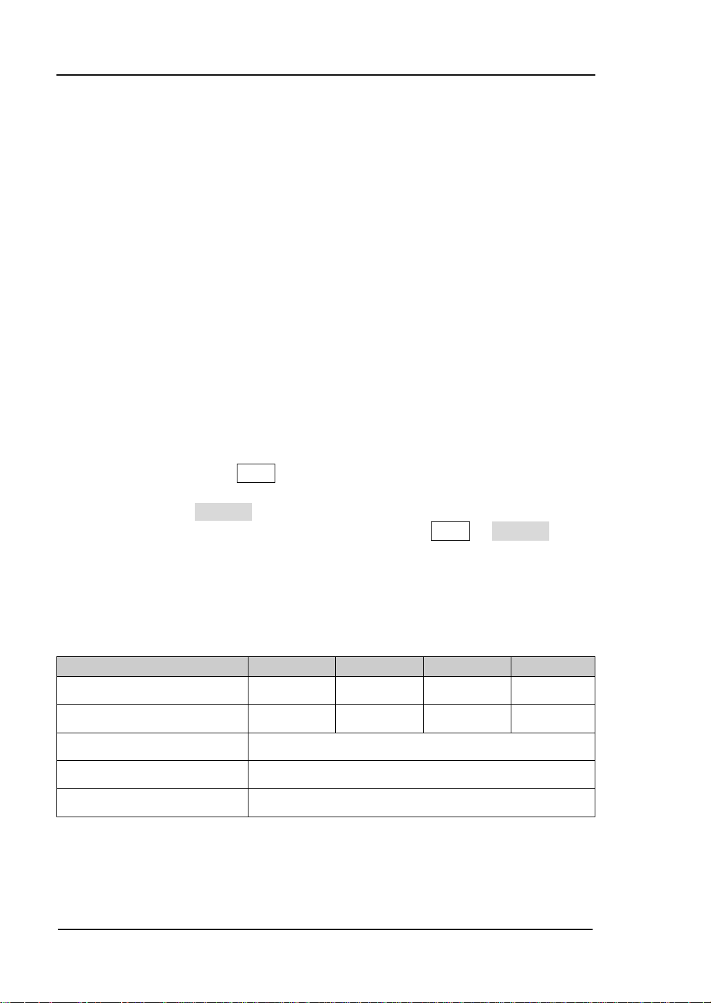
Content Conventions in this Manual:
This manual takes DS6104 for exam ple and the descriptions here have contai ne d all
the functions and performances of other models. The models of DS6000 series
include:
Analog bandwidth 1 GHz 1 GHz 600 MHz 600 MHz
Channels 4 2 4 2
Max. real-time sample rate 5 GSa/s
Standard memory depth 140 Mpts
Waveform refresh rate Up to 180,000 wfms/s
DS6000 User’s Guide
Page 17

RIGOL
XV
Contents
Guaranty and Declaration .......................................................................... I
Safety Requirement ................................................................................. II
General Safety Summary ............................................................................ II
Safety Terms and Symbols ......................................................................... IV
Measurement Category ............................................................................... V
Ventilation Requirement ............................................................................. VI
Working Environment .............................................................................. VII
General Care and Cleaning ......................................................................... IX
Environmental Considerations...................................................................... X
DS6000 Series Overview .......................................................................... XI
Document Overview .............................................................................. XIII
1 Quick Start ....................................................................................... 1-1
General Inspection .................................................................................. 1-2
Appearance and Dimensions .................................................................... 1-3
To Prepare the Oscilloscope for Use .......................................................... 1-4
To Remove the Cover ........................................................................ 1-4
To Adjust the Supporting Legs ........................................................... 1-5
To Connect to AC Power Supply ......................................................... 1-6
To Use the Battery ............................................................................ 1-7
Power-on Inspection ......................................................................... 1-8
To Connect the Probe ........................................................................ 1-9
Function Inspection ........................................................................ 1-10
Probe Compensation ....................................................................... 1-12
Front Panel Overview ............................................................................. 1-13
Rear Panel Overview .............................................................................. 1-14
Front Panel Function Overview ............................................................... 1-16
VERTICAL ...................................................................................... 1-16
HORIZONTAL ................................................................................. 1-18
TRIGGER ....................................................................................... 1-19
Run/Stop ....................................................................................... 1-19
Single ............................................................................................ 1-20
Auto .............................................................................................. 1-20
DS6000 User’s Guide
Page 18

RIGOL
XVI
Knob .............................................................................................. 1-21
Navigation Knob ............................................................................. 1-21
Menu ............................................................................................. 1-22
Record ........................................................................................... 1-22
MEAS ............................................................................................. 1-23
Clear .............................................................................................. 1-23
Print .............................................................................................. 1-23
User Interface ....................................................................................... 1-24
To Use the Security Lock ........................................................................ 1-29
To Use the Desk Mount Instrument Arm .................................................. 1-30
To Use the Rack Mount Kit ..................................................................... 1-31
Kit Parts List ................................................................................... 1-31
Installation Tool .............................................................................. 1-32
Installation Space ........................................................................... 1-32
Installation Procedures .................................................................... 1-33
To Use the Built-in Help System .............................................................. 1-36
2 To Set the Vertical System ...............................................................2-1
To Enable the Channel ............................................................................. 2-2
Channel Coupling .................................................................................... 2-3
Bandwidth Limit ...................................................................................... 2-4
Probe ..................................................................................................... 2-4
Input Impedance .................................................................................... 2-7
Waveform Invert ..................................................................................... 2-8
Vertical Scale .......................................................................................... 2-8
Vertical Expansion ................................................................................... 2-9
Amplitude Unit ........................................................................................ 2-9
Channel Label ....................................................................................... 2-10
Delay Calibration ................................................................................... 2-11
3 To Set the Horizontal System ...........................................................3-1
Delayed Sweep ....................................................................................... 3-2
Time Base Mode ..................................................................................... 3-4
Y-T Mode ......................................................................................... 3-4
X-Y Mode ......................................................................................... 3-5
Roll Mode ......................................................................................... 3-8
Horizontal Scale ...................................................................................... 3-9
Horizontal Reference ............................................................................. 3-10
DS6000 User’s Guide
Page 19

RIGOL
XVII
4 To Set the Sample System ............................................................... 4-1
Acquisition Mode ..................................................................................... 4-2
Normal ............................................................................................. 4-2
Average ........................................................................................... 4-2
Peak Detect ...................................................................................... 4-4
High Resolution ................................................................................ 4-4
Sample Mode .......................................................................................... 4-5
Real-time Sample.............................................................................. 4-5
Equivalent Sample ............................................................................ 4-5
Sample Rate ........................................................................................... 4-6
Memory Depth ........................................................................................ 4-8
Antialiasing ............................................................................................. 4-9
5 To Trigger the Oscilloscope ............................................................. 5-1
Trigger Source......................................................................................... 5-2
Trigger Mode ........................................................................................... 5-3
Trigger Coupling ...................................................................................... 5-5
Trigger Holdoff ........................................................................................ 5-6
Trigger Type ............................................................................................ 5-7
Edge Trigger ..................................................................................... 5-8
Pulse Trigger .................................................................................... 5-9
Slope Trigger .................................................................................. 5-11
Video Trigger .................................................................................. 5-14
Pattern Trigger ............................................................................... 5-16
RS232 Trigger ................................................................................. 5-18
I2C Trigger ..................................................................................... 5-20
SPI Trigger ..................................................................................... 5-23
CAN Trigger .................................................................................... 5-25
FlexRay Trigger ............................................................................... 5-28
USB Trigger .................................................................................... 5-30
Trigger Ouput Connector ........................................................................ 5-32
6 To Make Measurements ................................................................... 6-1
Math Operation ....................................................................................... 6-2
Addition ........................................................................................... 6-2
Subtraction....................................................................................... 6-3
Multiplication .................................................................................... 6-3
Division ............................................................................................ 6-4
DS6000 User’s Guide
Page 20

RIGOL
XVIII
FFT.................................................................................................. 6-5
Logic Operation ................................................................................ 6-8
Advanced Operation ........................................................................ 6-10
Auto Measurement ................................................................................ 6-13
Quick Measurement after Auto ........................................................ 6-14
One-key Measurement of 24 Parameters .......................................... 6-15
Frequency Counter Measurement ..................................................... 6-20
Measurement Setting ...................................................................... 6-21
Clear the Measurement ................................................................... 6-23
All Measurement ............................................................................. 6-24
Statistic Function ............................................................................ 6-25
Measurement History ...................................................................... 6-26
Cursor Measurement ............................................................................. 6-27
Manual Mode .................................................................................. 6-28
Track Mode .................................................................................... 6-31
Auto Mode ..................................................................................... 6-34
7 Protocol Decoding ............................................................................7-1
Parallel Decoding ..................................................................................... 7-2
RS232 Decoding (Option) ........................................................................ 7-5
I2C Decoding (Option) ........................................................................... 7-10
SPI Decoding (Option) ........................................................................... 7-13
CAN Decoding (Option) .......................................................................... 7-16
FlexRay Decoding (Option)..................................................................... 7-19
8 Reference Waveform ........................................................................8-1
To Enable REF Function ........................................................................... 8-2
To Set the Color ...................................................................................... 8-3
To Select REF Source ............................................................................... 8-4
To Save to Internal Memory ..................................................................... 8-4
To Adjust REF Waveform Display .............................................................. 8-4
To Export to Internal or External Memory .................................................. 8-5
To Import from Internal or External Memory ............................................. 8-5
9 Pass/Fail Test ...................................................................................9-1
To Enable Pass/Fail Test Function ............................................................. 9-2
To Select Source ..................................................................................... 9-3
Mask Range ............................................................................................ 9-3
Test and Output ...................................................................................... 9-3
DS6000 User’s Guide
Page 21

RIGOL
XIX
To Save the Test Mask ............................................................................. 9-4
To Load the Test Mask ............................................................................. 9-5
10 Waveform Recording ..................................................................... 10-1
Waveform Recording ............................................................................. 10-2
Waveform Playback ............................................................................... 10-4
Waveform Analysis ................................................................................ 10-6
Analysis Based on Trace .................................................................. 10-9
Analysis Based on Pass/Fail Mask ................................................... 10-10
11 Display Control .............................................................................. 11-1
To Select the Display Type ..................................................................... 11-2
To Set the Persistence Time ................................................................... 11-3
To set the Waveform Brightness ............................................................. 11-5
To Set the Screen Grid ........................................................................... 11-5
To Set the Grid Brightness ...................................................................... 11-5
To Set the Menu Display ........................................................................ 11-5
12 Store and Recall ............................................................................. 12-1
Storage System ..................................................................................... 12-2
Storage Type ......................................................................................... 12-3
Internal Store and Recall ........................................................................ 12-5
External Store and Recall ....................................................................... 12-7
Disk Management .................................................................................. 12-9
To Select File Type ........................................................................ 12-10
To Create a New File or Folder ....................................................... 12-11
To Delete a File or Folder............................................................... 12-14
To Rename a File or Folder ............................................................ 12-14
To Clear the Local Memory ............................................................ 12-15
Factory ............................................................................................... 12-16
13 System Function Setting ................................................................ 13-1
Remote Interface Configuration .............................................................. 13-2
LAN Setting .................................................................................... 13-2
USB Device .................................................................................... 13-6
To Set the GPIB Address ................................................................. 13-6
System-related ...................................................................................... 13-7
Sound ............................................................................................ 13-7
Language ....................................................................................... 13-7
DS6000 User’s Guide
Page 22

RIGOL
XX
System Information ........................................................................ 13-7
Power-off Recall ............................................................................. 13-8
System Time .................................................................................. 13-9
Self-calibration Information ........................................................... 13-10
Screen ......................................................................................... 13-11
Error Information .......................................................................... 13-12
Self-calibration ............................................................................. 13-13
Power Status ................................................................................ 13-14
External Trigger Impedance ........................................................... 13-14
Aux Output .................................................................................. 13-15
Reference Clock ............................................................................ 13-16
Option Management ..................................................................... 13-17
To Print the Waveform ......................................................................... 13-18
To Connect the Print Device ........................................................... 13-18
Normal Print ................................................................................. 13-19
PictBridge Print ............................................................................. 13-20
14 Remote Control ............................................................................. 14-1
Remote Control via USB ......................................................................... 14-2
Remote Control via LAN ......................................................................... 14-6
Remote Control via GPIB ........................................................................ 14-9
15 Troubleshooting ............................................................................ 15-1
16 Specifications ................................................................................ 16-1
17 Appendix ....................................................................................... 17-1
Appendix A: Options and Accessories ...................................................... 17-1
Appendix B: Warranty ............................................................................ 17-2
Appendix C: Any Question or Comment? ................................................. 17-3
Index ......................................................................................................... 1
DS6000 User’s Guide
Page 23

1 Quick Start RIGOL
1-1
1 Quick Start
This chapter introduces the preparations when using the oscilloscope for the first
time, the front panel, rear panel and user interface of the oscilloscope as well as the
using method of the built-in help system.
The contents of this chapter:
General Inspection
Appearance and Dimensions
To Prepare the Oscilloscope for Use
Front Panel Overview
Rear Panel Overview
Front Panel Function Overview
User Interface
To Use the Security Lock
To Use the Desk Mount Instrument Arm
To Use the Rack Mount Kit
To Use the Built-in Help System
DS6000 User’s Guide
Page 24

RIGOL 1 Quick Start
1-2
General Inspection
1. Inspect the shipping container for damage.
Keep the damaged shipping container or cushioning material until the contents
of the shipment have been checked for completeness and the instrument has
passed both electrical and mechanical tests.
The consigner or carrier shall be liable for the damage to instrument resulting
from shipment. RIGOL would not be responsible for free maintenance/rework
or replacement of the unit.
2. Inspect the instrument.
In case of any damage, or defect, or failure, notify your RIGOL sales
representative.
3. Check the Accessories
Please check the accessories according to the packing lists. If the accessories
are incomplete or damaged, please contact your RIGOL sales representative.
DS6000 User’s Guide
Page 25
1 Quick Start RIGOL
1-3
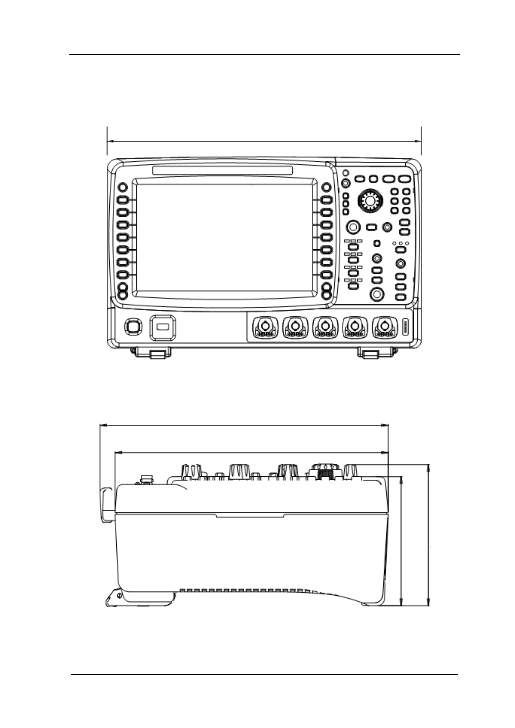
242
113
123.8
Appearance and Dimensions
399
Figure 1-1 Front View Unit: mm
255.3
Figure 1-2 Side View Unit: mm
DS6000 User’s Guide
Page 26
RIGOL 1 Quick Start
1-4
To Prepare the Oscilloscope for Use
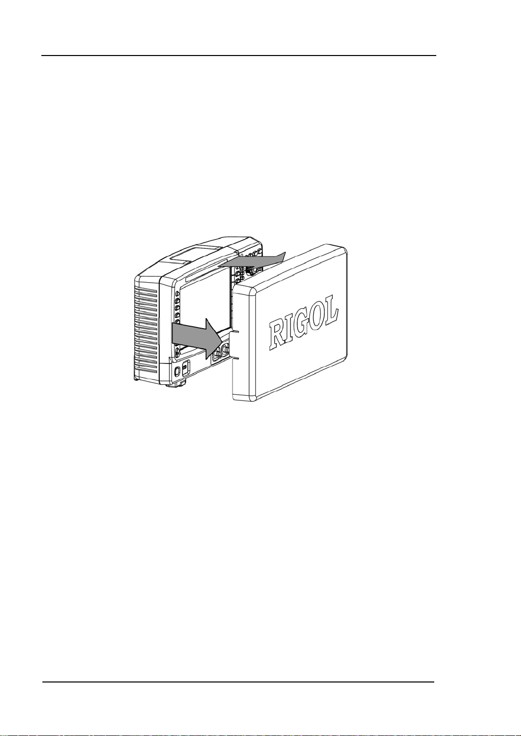
To Remove the Cover
Before using the oscilloscope, remove the front panel cover by grasping the
transverse grab on each side and pull them in the arrow directions as shown in the
figure below.
Figure 1-3 To Remove the Cover
DS6000 User’s Guide
Page 27
1 Quick Start RIGOL
1-5
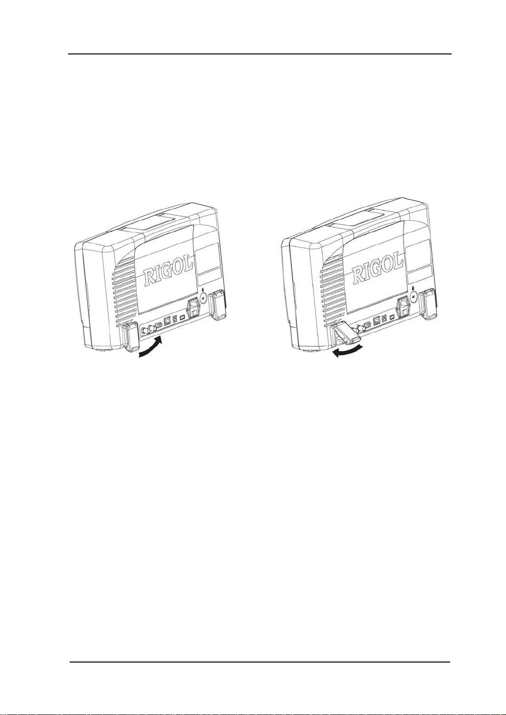
To Adjust the Supporting Legs
Adjust the supporting legs properly to use them as stands to tilt the oscilloscope
upwards for stable placement of the oscilloscope and better operation and
observation of the display. Unfold or fold the supporting legs in the arrow directions
as shown in the figures below.
Figure 1-4 To Adjust the Supporting Legs
DS6000 User’s Guide
Page 28
RIGOL 1 Quick Start
1-6
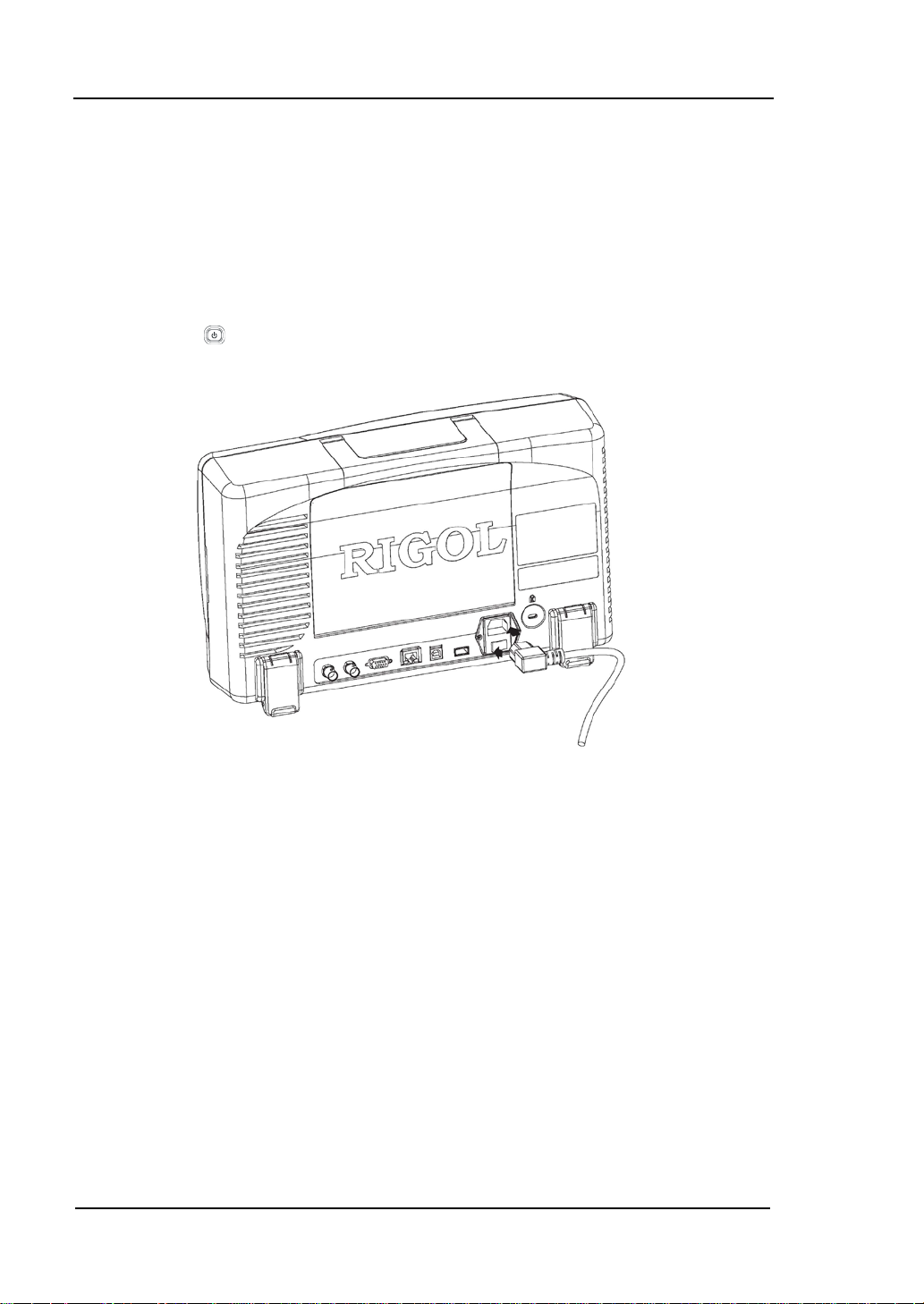
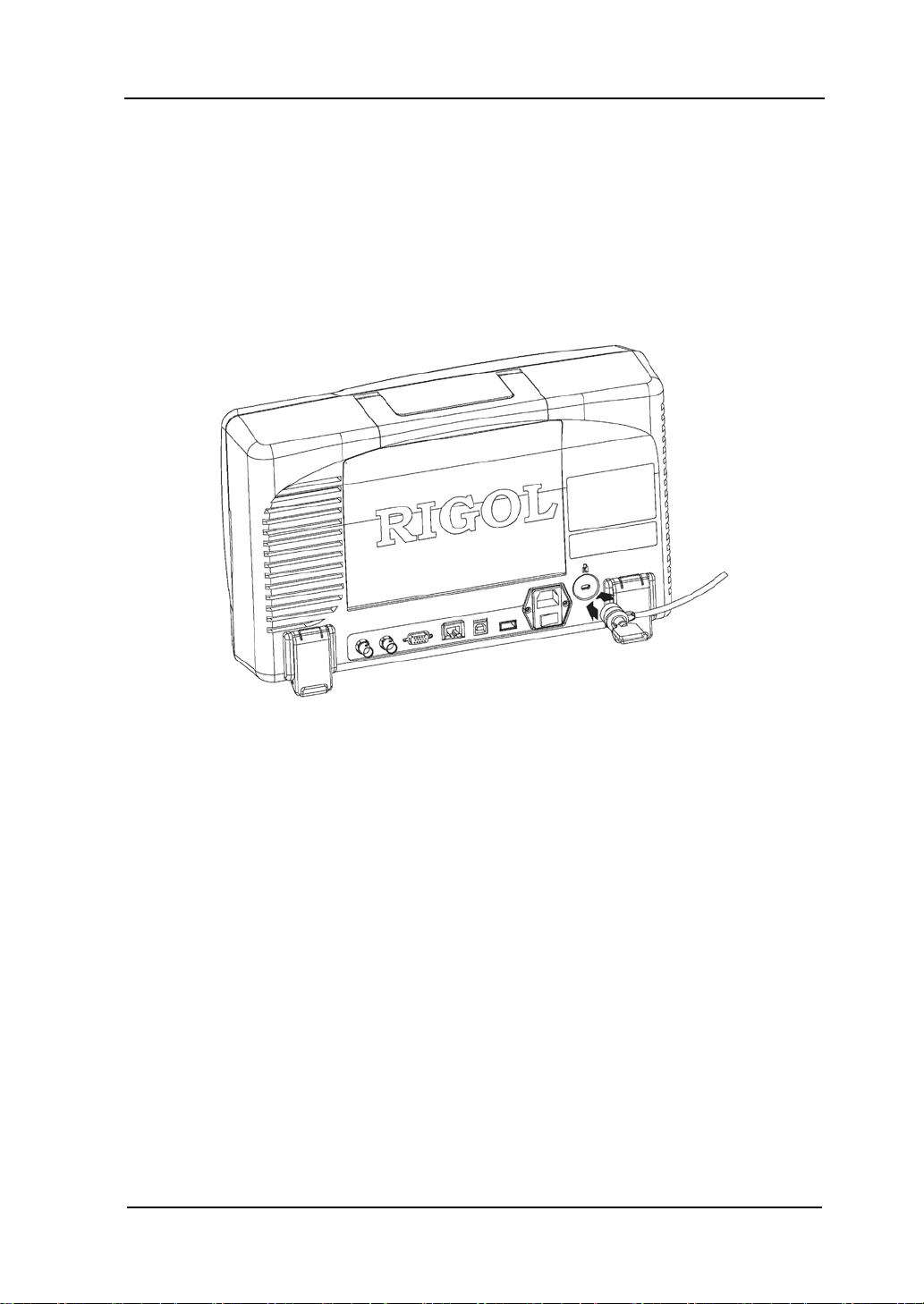
To Connect to AC Power Supply
This oscilloscope accepts two kinds of AC power supply: 100-127V, 4 5-440Hz and
100-240V, 45-65Hz. Please use the power cord supplied with the accessories to
connect the oscilloscope to the power source as shown in the figure below. After the
power switch under the power plug is turned on, the oscilloscope is energized and
the power key
at the lower-left corner of the front panel is in breath state.
Figure 1-5 To Connect to AC Power Supply
DS6000 User’s Guide
Page 29
1 Quick Start RIGOL
1-7
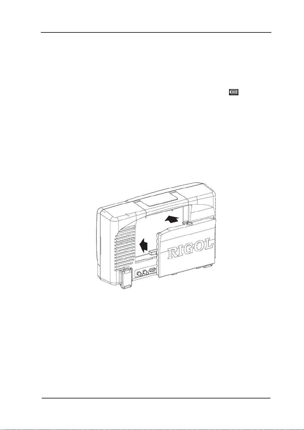
To Use the Battery
This oscilloscope also provides rechargeable battery on your option. Please install the
battery as shown in the figure below. When leaving the factory, the battery holds
certain electric quantity. When use the battery alone, a battery icon
displayed at the lower-right corner of the screen and the remaining electric quantity
is indicated (no display when the AC p ower and battery are used at the same time).
When the electric quantity of the battery is too low , “Low Battery!” will be displayed.
If recharge is needed, please install the battery correctly and then follow the
instructions in “To Connect to AC Power Supply” to connect the oscilloscope to
AC power supply to recharge the battery. It needs about 15 hours for the battery to
finish recharging.
will be
Figure 1-6 To Install the Battery
DS6000 User’s Guide
Page 30

RIGOL 1 Quick Start
1-8
Power-on Inspection
When the oscilloscope is energized, press the power key
of the front panel to turn on the oscilloscope. During the start-up process, the
oscilloscope performs a series of self-tests and you can hear the sound of relay
switching. After the self-test is finished, the welcome screen is displayed and you can
view the Option Type, Option name, Option Edition and Left time of the option
currently installed in the “Installed Options” pop-up dialog box on the screen. When
the instrument is shipped, a trial version of the option is provided and the left time is
about 2000 minutes. Press UTIL System SelfCalInfo to view the self-test
results.
at the lower-left corner
DS6000 User’s Guide
Page 31

1 Quick Start RIGOL
1-9
Model
Description
To Connect the Probe
RIGOL provides passive and active probes for DS6000 series oscilloscopes. For
detailed technical information of the probes, please refer to corresponding Probe
User’s Guide. The following are the probes recommended for this oscilloscope.
RP5600
600 MHz, passive probe, standard, auto detection
RP3500 500 MHz, passive probe, optional, auto detection
RP6150 1.5 GHz, passive probe, DS610X standard, auto detection
RP7150 1.5 GHz, active probe, optional, auto detection
Connect the Probe:
1. Connect the BNC terminal of the probe to a channel BNC connector of the
oscilloscope at the front panel.
2. Connect the probe tip to the circuit point under test and connect the ground
alligator clip of the probe to the circuit ground terminal.
Figure 1-7 To Connect the Probe
DS6000 User’s Guide
Page 32
RIGOL 1 Quick Start
1-10
Compensation Signal
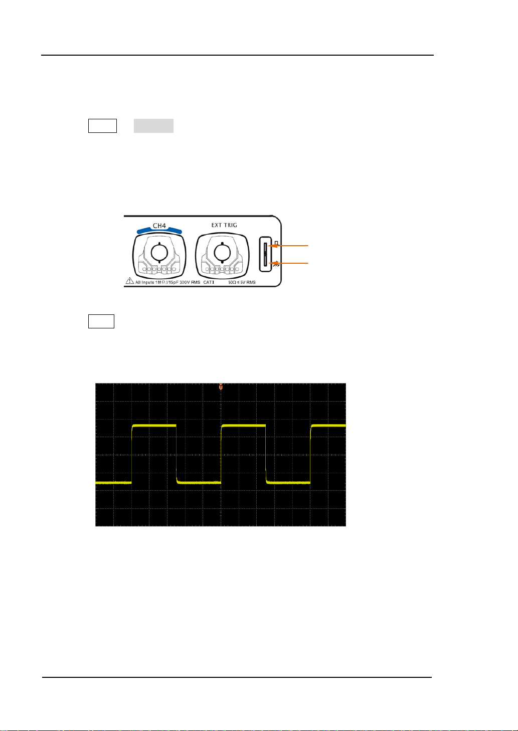
Function Inspection
1. Press SAVE Factory to restore the oscilloscope to its default configuration.
2. Connect the ground alligator clip of the probe to the “Ground Terminal” under the
probe compensation signal output terminal
3. Use the probe to connect the input terminal of CH1 of the oscilloscope and the
“Compensation Signal Output Terminal” of the probe.
Output Terminal
Ground Terminal
Figure 1-8 To Use the Compensation Signal
4. Press Auto.
5. Observe the wavefor m on the displa y. In normal condition, the display should be
a square waveform as shown in the figure below:
Figure 1-9 Square Wavef orm
6. Use the same method to test the other channels. If the square waveforms
actually shown do not match that in the figure above, please perform “Probe
Compensation” in the next section.
DS6000 User’s Guide
Page 33
1 Quick Start RIGOL
1-11
Tip
probe compensation adjustment and can not be used for calibration.
WARNING
To avoid electric shock during the use of probe, please mak e sure that the
insulated wire of the probe is in good condition and do not touch the
metallic part of the probe when the probe is connected to hi gh voltage
source.
The signal output from the probe compensation connector can only be used for
DS6000 User’s Guide
Page 34
RIGOL 1 Quick Start
1-12
Probe Compensation
When the probes are used for the first time, you should compensate the probes to
match the input channels of the oscilloscope. Non-compensated or poorly
compensated probes may cause measurement inaccuracy and error. The probe
compensation procedures are as follows.
1. Perform steps 1, 2, 3 and 4 of “Function Inspection” in the previous section.
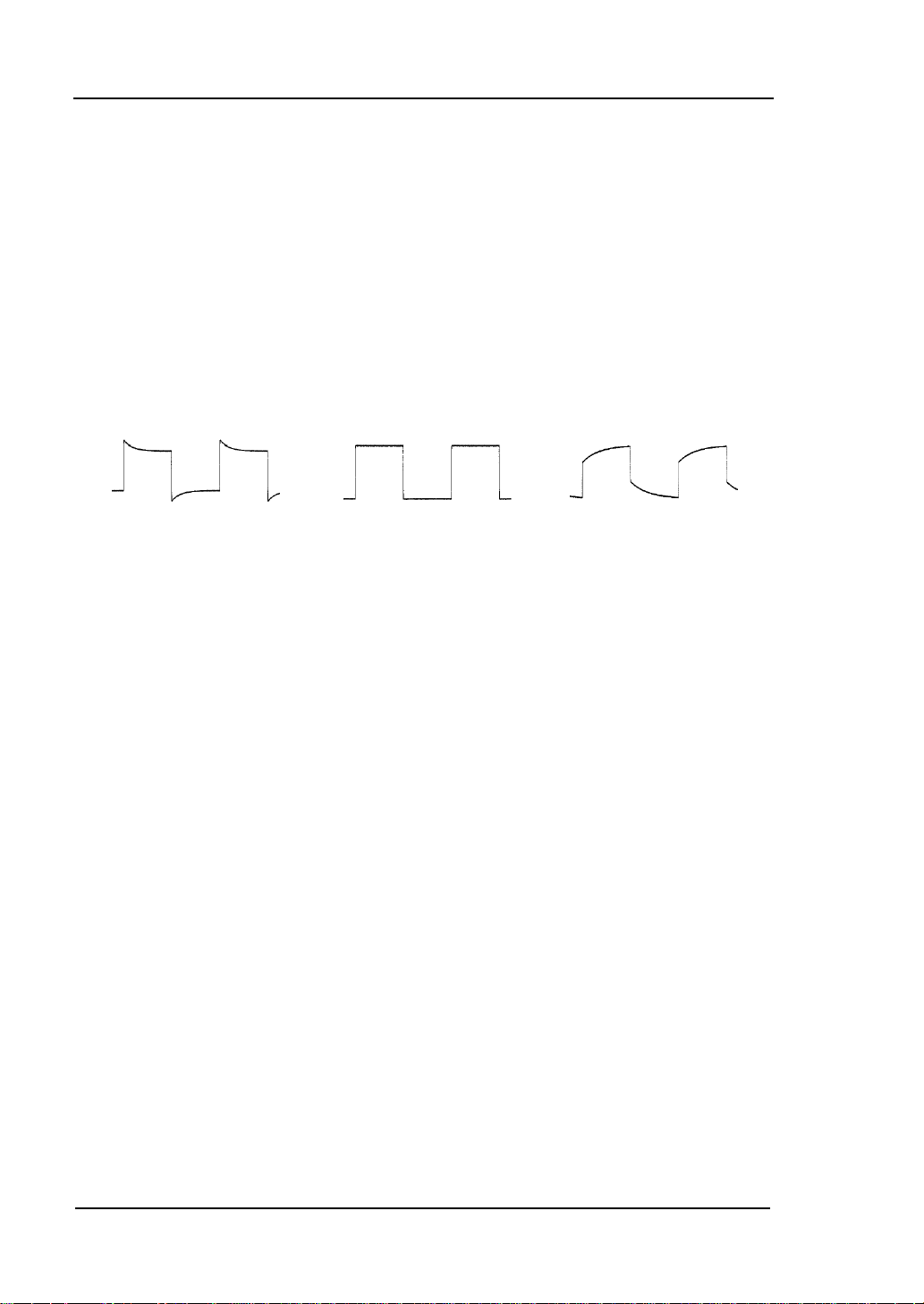
2. Check the displayed waveforms and compare them with the following figures.
Over compensated Correctly compensated Under compensated
Figure 1-10 Probe Compensation
3. Use a nonmetallic driver to adjust the low-frequency compensation adjustment
hole on the probe until the displayed waveform is as the “Correctly
compensated” in the figure above.
DS6000 User’s Guide
Page 35

1 Quick Start RIGOL
1-13
1 2
4 5 6 7 8
15 16 17 18 19 20
Front Panel Overview
3
9
10
11
12
13
14
Figure 1-11 Front Panel Overview
Table 1-1 Front Panel Description
No. Description No. Description
1
2
3
4
5
6
7
8
9
10
DS6000 User’s Guide
Menu
LCD
Knob
Clear
Auto
Navigation Knob
Run/Stop
Single
Record/Playback
Function Menu
11
12
13
14
15
16
17
18
19
20
HORIZONTAL Area
Measurement Setting and Quick Print
VERTICAL Area
TRIGGER Area
Power Key
USB HOST Port
Analog Channel Input Terminal
EXT TRIG Input Terminal
Probe Compensation Signal Output Terminal
Probe Compensation Ground Terminal
Page 36
RIGOL 1 Quick Start
1-14
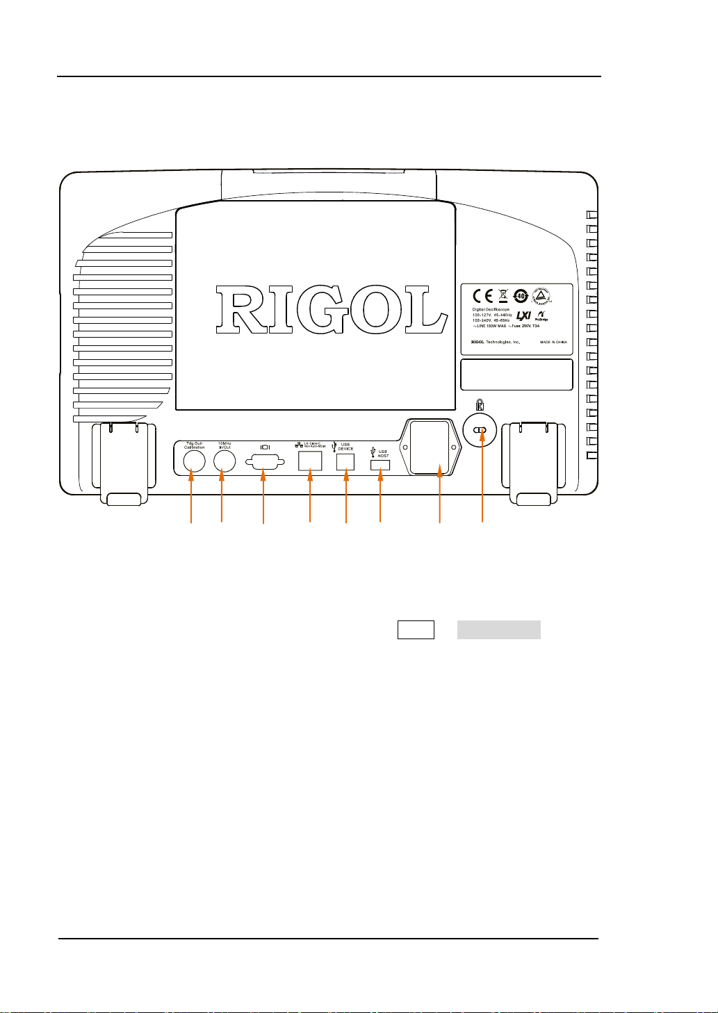
Rear Panel Overview
1 2 3 4 5 6 7 8
Figure 1-12 Rear Panel Overview
1. Trig Out/Calibration
This connector can output various signals (press UTIL Aux Output to select
the desired output type.):
1) TrigOut: after this type is selected, the oscilloscope output a signal that can
reflect the current capture rate of the oscilloscope at each trigger.
2) Fast: after this type is selected, the oscilloscope can output a fast edge
signal which can be used in the self-calibration of the oscilloscope.
3) GND: after this type is selected, the oscilloscope can output a gr ound l evel .
4) PassFail: after this type is selecte d , the osci lloscope will output a pulse
signal when failed waveforms are detected. Connect this signal to other
control systems to conveniently view the test results.
2. Reference Clock
Provide more precise sample clock signal for the oscilloscope and it can also
DS6000 User’s Guide
Page 37

1 Quick Start RIGOL
1-15
synchronize two or more oscilloscope clocks.
3. Video Output
Through this interface, the oscilloscope can be connected to external monitors
such as projector to get clearer waveform display. Note that at this point, the
display of the oscilloscope is still valid.
4. LAN
Through this interface, the oscilloscope can be connected to the network for
remote control. As the oscilloscope conforms to the LXI-C ins trument standard, a
test system can be built quickly .
5. USB DEVICE
Through this interface, the oscilloscope can be connected to PictBridge printer to
print w aveform data or be connected to PC to control the oscilloscope through PC
software.
6. USB HOST
Through this interface, the oscilloscope can be connected to normal printers to
print waveform data or be connected to a USB stor age device to store waveform
files.
GPIB interface communication can be realized by using the USB-GPIB interface
converter (optional) provided by RIGOL.
Note that the front panel also provides this interface.
7. AC Input/Switch
When using AC power supply, please insert the power cord plug into the socket
vertically and use the switch under the socket to power the oscilloscope on or off .
8. Lock Hole
Use the security lock (please buy it yourself) to lock the oscilloscope to fixed
location.
DS6000 User’s Guide
Page 38
1-16
MATH
RIGOL 1 Quick Start
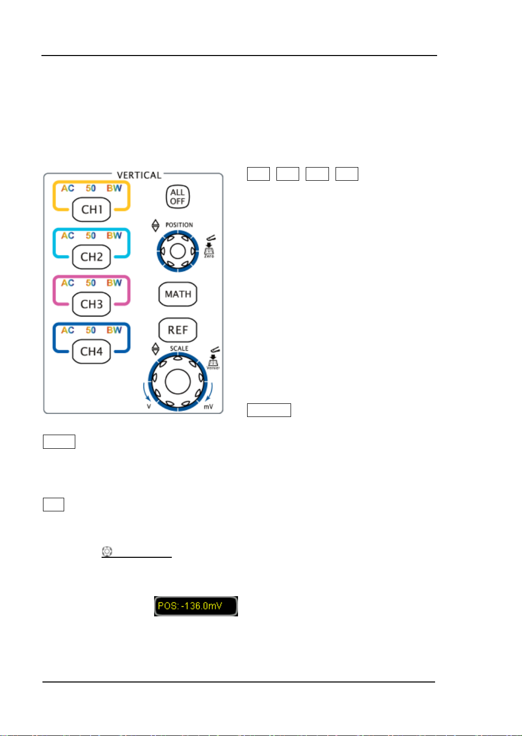
Front Panel Function Overview
VERTICAL
CH1, CH2, CH3, CH4: analog input
channels. The four channels are marked
by different colors which are also used to
mark both the waveforms on the screen
and the channel input connectors. Press
any key to turn on the corresponding
channel menu and press again to turn
off the channel.
AC: illuminated when AC channel
coupling mode is enabled.
50: illuminated when the channel input
impedance is 50Ω.
BW: illuminated when the bandwidth
limit is turned on.
ALL OFF: press this key to turn off all
the channels that have been turned on.
: press this key to turn on the math operation and decoding function menus
under which to perform add, subtract, multiply, divide, FFT, logic and advanced
operations as well as parallel, RS232, SPI, I2C, CAN and FlexRay decodings.
REF: press this key to turn on the reference waveform function to compare the
waveform actually tested with the reference waveform to decide circuit failures.
VERTICAL
waveform. Turn clockwise to increase the position and turn counterclockwise to
decrease. During the modification, the waveform would move up and down and the
POSITION: modify the vertical position of the current channel
position message (e.g.
would change accordingly. Press down this knob to quickly reset the vertical position
to zero.
) at the lower-left corner of the screen
DS6000 User’s Guide
Page 39

1 Quick Start RIGOL
1-17
VERTICAL SCALE: modify the vertical scale of the current channel. Turn
clockwise to decrease the scale and turn counterclockwise to increase. During the
modificat ion , the amplitude of the waveform would enlarge or reduce and the scale
information (e.g.
) at the lower side of the screen would change
accordingly. Press down this knob to quickly switch the vertical scale adjustment
modes between “Coarse” and “Fine”.
DS6000 User’s Guide
Page 40
RIGOL 1 Quick Start
1-18
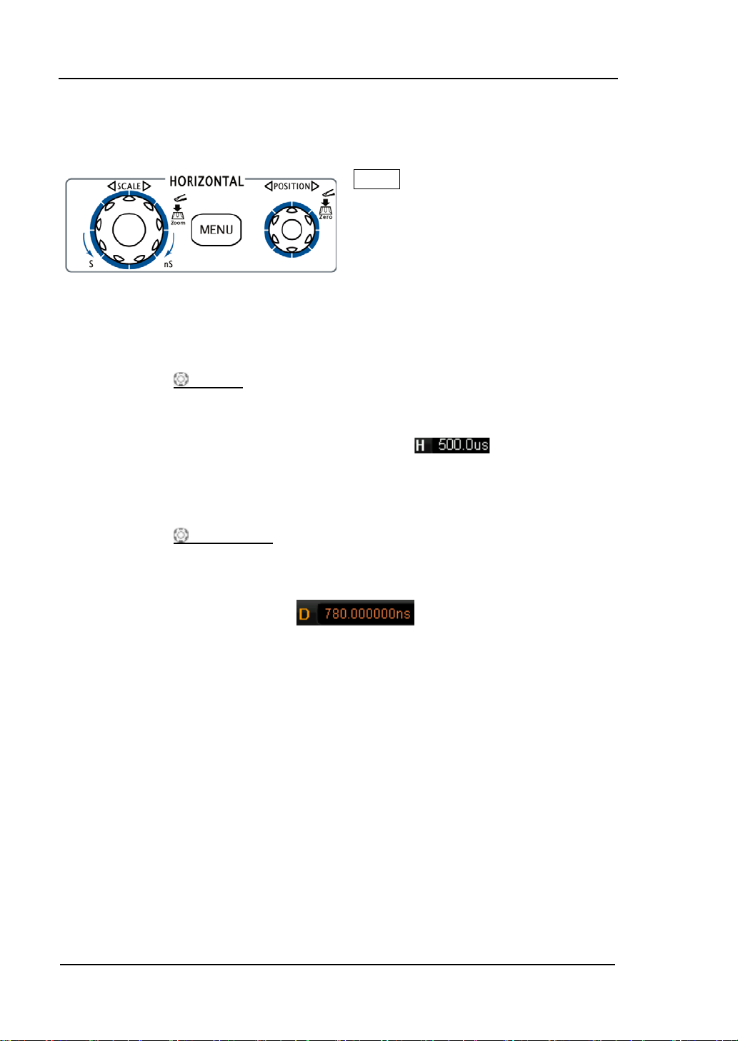
MENU
HORIZONTAL
: press this key to turn on the
horizontal control menu under which to
turn on or off the delayed sweep
function, switch between diff e re nt time
base modes, switch between “Coarse”
and “Fine” adjustment of scale as well
as modify the horizontal reference
setting.
HORIZONTAL SCALE: modify the horizontal time base. Turn clockwise to
reduce the time base and turn counterclockwise to increase the time base. During
the modification, waveforms of all the channels will be displayed in expanded or
compressed mode and the time base message (e.g.
of the screen would change accordingly. Press down this knob to quickly switch to
delayed sweep state.
HORIZONTAL
POSITION: modify the trigger position. The trigger point
moves left or right relative to the center of the screen when you turn the knob.
During the modification, waveforms of all the channels would move right or left and
) at the upper side
the trigger position message (e.g.
) at the upper-right corner of
the screen would change accordingly. Press down this knob to quickly restore the
trigger position (or the delayed sweep position).
DS6000 User’s Guide
Page 41

1 Quick Start RIGOL
1-19
MODE
Auto
TRIGGER
: press this key to switch the trigger mode to
Normal or Single and the corresponding state backlight
of the current trigger mode would be illuminated.
TRIGGER
clockwise to increase the level and turn counterclockwise
to reduce the level. During the modification, the trigger
level line moves up and down and the value in the trigger
LEVEL: modify the trigger level. Turn
,
Run/Stop
level message box (e.g.
lower-left corner of the screen changes accordingly. Press
down the knob to quickly reset the trigger level to zero
point.
MENU: press this key to turn on the trigger operation
menu. This oscilloscope provides various trigger types.
FORCE: in Normal and Single trigger modes, press this
key to generate a trigger signal forcefully.
50%: press this key to set the trigger level to the vertical
midpoint of the trigger signal amplitude.
Press this key to set the state of the oscilloscope to “Run”
or “Stop”. In “Run” state, the key is illuminated in yellow
and red in “Stop” state.
) at the
DS6000 User’s Guide
Page 42

RIGOL 1 Quick Start
1-20
displayed.
Single
Auto
Press this key to set the trigger mode to “Single”. In
single trigger mode, the oscilloscope generates a trigger
when the trigger conditions are met and then stops.
Press this key to turn on the waveform auto setting
function. The oscilloscope will automatically adjust the
vertical scale, horizontal time base and trigger mode
according to the input signal to realize optimum
waveform display and provide quick parameter
measurement (please refer to Quick Measurement
after Auto
Note: auto setting requires that the frequency of the
signal under test should be no lower than 50 Hz, the duty
cycle be greater than 1% and the amplitude be at least
20 mVpp. If the parameters exceed these limits, “Auto
failed!” would be displayed after pressing this key and the
quick parameter measurement menu might not be
).
DS6000 User’s Guide
Page 43

1 Quick Start RIGOL
1-21
Adjust waveform brightness:
Knob
In non-menu-operation mode (menu is hidden), turn this
knob to adjust the brightness of waveform display. The
adjustable range of the brightness is from 0% to 100%.
Turn clockwise to increase the brightness and
counterclockwise to reduce. Press down this knob to
reset the brightness to 50%.
You can also press DISP WaveIntensity and use
the knob to adjust the waveform brightness.
Multifunctional Knob (the backlight goes on
during operation):
In menu operation, press some menu softkey and turn
the knob to select the submenus under this menu and
then press down the knob to select the currently selected
submenu. It can also be used to modify parameters and
filename input.
Navigation Knob
For example, this knob can be used to quickly locate the waveform f rame (“Curr ent
Frame” menu) to be played back in the waveform playback function. Similar menus
include trigger holdoff, pulse width setting, slope time etc.
DS6000 User’s Guide
This knob provides quick Adjust/Locate function
for numerical parameters with relatively large
settable range. Turn clockwise
(counter-clockwise) to increase (reduce) the
value. Note that the inner knob is used for fine
adjustment and the outer knob for coarse
adjustment. The change rate of the value
depends on the rotation amplitude of the outer
knob.
Page 44

RIGOL 1 Quick Start
1-22
ACQ: press this key to enter sample setting
DISP
Menu
menu to set the acquisition mode, the sampling
mode, the memory depth and the antialiasing
function of the oscilloscope.
CURS: press this key to enter cursor
measurement menu. The oscilloscope provides
three cursor modes: manual, track and auto.
SAVE: press this key to enter file store and
recall interface. The storable file types include
traces, waveforms, setups, picture and CSV.
Support internal and external storage as well as
disk management.
: press this key to enter display setting menu to set the display type,
persistence time, wave intensity , grid type, grid brightness and menu display time of
the waveform.
UTIL: press this key to enter the system fun ction setting menu to set the
system-related functions or parameters, such as I/O setting, sound and language.
Support some advanced f unctions such as pa ss/fail test, waveform record and print
setting.
HELP: press this key to turn on the help interface. For detailed information, please
refer to the introduction in “To Use the Built-in Help System”.
Record
Play/Pause: in stop or pause state, press this key to play back the
waveform and press again to pause the play. The backlight is
illuminated in yellow.
Stop: press this key to stop the waveform in record or playback
mode. The backlight is illuminated in orange.
Record: press this key to start recording the waveform. The
backlight is illuminated in red.
DS6000 User’s Guide
Page 45

1 Quick Start RIGOL
1-23
MEAS
Clear
Press this key to enter the measurement menu which supports
measurement parameter setting, all measure, statistic analysis and
counter. Press MENU at the left of the screen to quickly turn on the
selecting menu of the 24 measurement parameters and easily
realize “one-key” measurement of common parameters.
Press this key to clear all the waveforms on the screen. If the
oscilloscope is in “Run” state, new waveforms will still be displayed.
Press this key to execute print function or save the screen in the
USB storage device. If the oscilloscope is currently connected to a
printer (PictBridge or normal) and the printer is in idle state, press
this key to execute pri nt f unction. If no printer but an USB storage
device is currently connected, press this key to save the screen to
the USB storage device in “.bmp” format (if the current storag e
type is picture, the screen will be saved in the USB storage device
in the specified picture format). When printer and USB storage
device are connected at the same time, the printer enjoys higher
priority.
DS6000 User’s Guide
Page 46

RIGOL 1 Quick Start
1-24
2 4 6 8 10
User Interface
DS6000 oscilloscope provides 10.1 inches, WVGA (800*480) 160,000 color TFT LCD.
What is worth mentioning is that the 14-grid ultra-wide screen makes you view
“longer” waveform.
1 3 5 7 9 11
12 14 16 18
13 15 17
Figure 1-13 User Interface
1. Auto Measurement Menu
Provide 12 horizontal (HORIZONTAL) and 12 vertical (VERTICAL)
measurement parameters. Press the softkey at the left of the screen to
activate the corresponding measurement item.
DS6000 User’s Guide
Page 47

1 Quick Start RIGOL
1-25
2. Channel Label/Waveform
Different channels are marked by different colors and the color of the
waveform complies with the color of the channel.
3. Status
Available states include RUN, STOP, T’D (triggered), WAIT and AUTO.
4. Horizontal Time Base
Represent the time per grid on the horizontal axis on the screen.
Use HORIZONTAL
SCALE to modify this parameter. The range
available is from 500 ps to 1.000 ks.
5. Sample Rate/Memory Depth
Display the current sample rate and memory depth of the oscilloscope.
Use HORIZONTAL
SCALE to modify this parameter.
6. Waveform Memory
Provide the schematic diagram of the memory position of the waveform
currently on the screen.
waveform on the
screen
7. Trigger Position
Display the trigger positions of the waveform in the waveform memory and
on the screen.
8. Trigger Position
Use HORIZONTAL
POSITION to modify this parameter. Press down
the knob to automatically set the parameter to zero.
9. Trigger Type
Display the currently selected trigger type and trigger condition setting.
Different labels are displayed when different trigger types are selected.
For example,
represents triggering on the rising edge in “Edge” trigger.
DS6000 User’s Guide
Page 48

RIGOL 1 Quick Start
1-26
10. Trigger Source
Display the trigger source currently selected (CH1-CH4, EXT, EXT/5 or AC
Line). Different labels are displayed when different trigger sources are
selected and the color of the trigger parameter area will c hange accordingly.
For example,
denotes that CH1 is selected as the trigger source.
11. Trigger Level
at the right of the screen is the trigger level label and the trigger
level value is displayed at the upper-right corner of the screen.
When Using TRIGGER
trigger level value will change with the up and down of
Note: in slope trigger, there are two trigger level labels (
LEVEL to modify the trigger level, the
.
and ). For
detailed information, please refer to the introduction in “Vertical Window”
on page 5-12.
12. CH1 Vertical Scale
Display the voltage value per grid of CH1 waveform vertically.
Use VIRTICAL
SCALE to modify this parameter.
The following labels will be provided according to the current channel
setting: “Channel Coupling” (such as
“Bandwidth Limit” (such as
“Input Impedance” (such as
when bandwidth limit is enabled) and
when the input impedance is 50 Ω).
in AC coupling),
13. CH2 Vertical Scale
Display the voltage value per grid of CH2 waveform vertically.
Use VIRTICAL
SCALE to modify this parameter.
The following labels will be provided according to the current channel
setting: “Channel Coupling” (such as
“Bandwidth Limit” (such as
“Input Impedance” (such as
when bandwidth limit is enabled) and
when the input impedance is 50 Ω).
in AC coupling),
14. CH3 Vertical Scale
Display the voltage value per grid of CH3 waveform vertically.
Use VIRTICAL
SCALE to modify this parameter.
The following labels will be provided according to the current channel
setting: “Channel Coupling” (such as
“Bandwidth Limit” (such as
when bandwidth limit is enabled) and
in AC coupling),
DS6000 User’s Guide
Page 49
1 Quick Start RIGOL
1-27
“Input Impedance” (such as when the input impedance is 50 Ω).
15. CH4 Vertical Scale
Display the voltage value per grid of CH4 waveform vertically.
Use VIRTICAL
SCALE to modify this parameter.
The following labels will be provided according to the current channel
setting: “Channel Coupling” (such as
“Bandwidth Limit” (such as
“Input Impedance” (such as
when bandwidth limit is enabled) and
when the input impedance is 50 Ω).
in AC coupling),
16. Message Box
Display prompt messages.
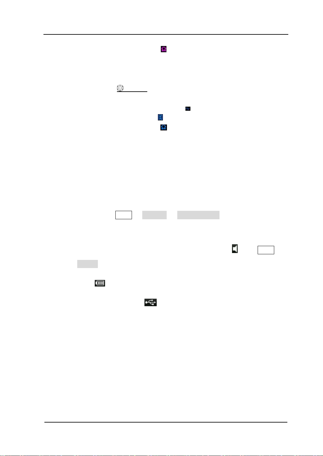
17. Notification Area
Display system time, sound icon, battery icon and USB storage device icon.
System Time: displayed in “hh:mm (hour:minute)” format. When
printing or storing the waveform, the output file will contain this tim e
message. Press UTIL System System Time to set through the
following format:
yyyy -mm-dd hh-mm-ss (year-month-date hour-minute-second)
Sound Icon: when sound is turne d on, this area displa ys
Sound to turn the sound on or off.
Battery Icon: when the battery is used for power supply, this area
displays
.
USB storage device: when the oscilloscope detects a USB storage
device, this area displays
.
DS6000 User’s Guide
. Press UTIL
Page 50
RIGOL 1 Quick Start
1-28
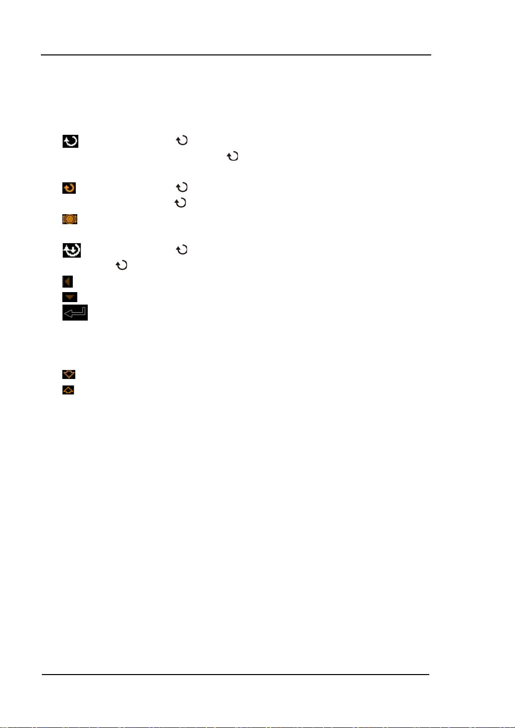
18. Operation MENU
Press any softkey to activate the corresponding menu. The following
symbols might be displayed in the menu:
Denote that
items. The backlight of
on the front panel can be used to select parameter
turns on when parameter selection is
valid.
Denote that
backlight of
Denote that you can use the Navigation Konb to quickly adjust/locate
can be used to modify parameter values. The
turns on when parameter input is valid.
parameters.
Denote that
can be used to adjust parameters and then press
to select the parameter.
Denote that the current menu has several options.
Denote that the current menu has a lower level menu.
Press this key to return to the previous menu.
Note: the following directi on keys might appear in the grid at the lower-left
corner of the menu bar:
Denote that you can turn on the next page menu.
Denote that you can turn back the previous page menu.
DS6000 User’s Guide
Page 51
1 Quick Start RIGOL
1-29
To Use the Security Lock
If needed, you can use the security lock (please buy it yourself) to lock the
oscilloscope to a fixed location. The method is as follows, align the lock with the lock
hole and plug it into the lock hole vertically, turn the key clockwise to lock the
oscilloscope and then pull the key out.
Figure 1-14 To Use the Security Lock
Note: do not insert other articles into the security lock hole to avoid damaging the
instrument.
DS6000 User’s Guide
Page 52
RIGOL 1 Quick Start
1-30
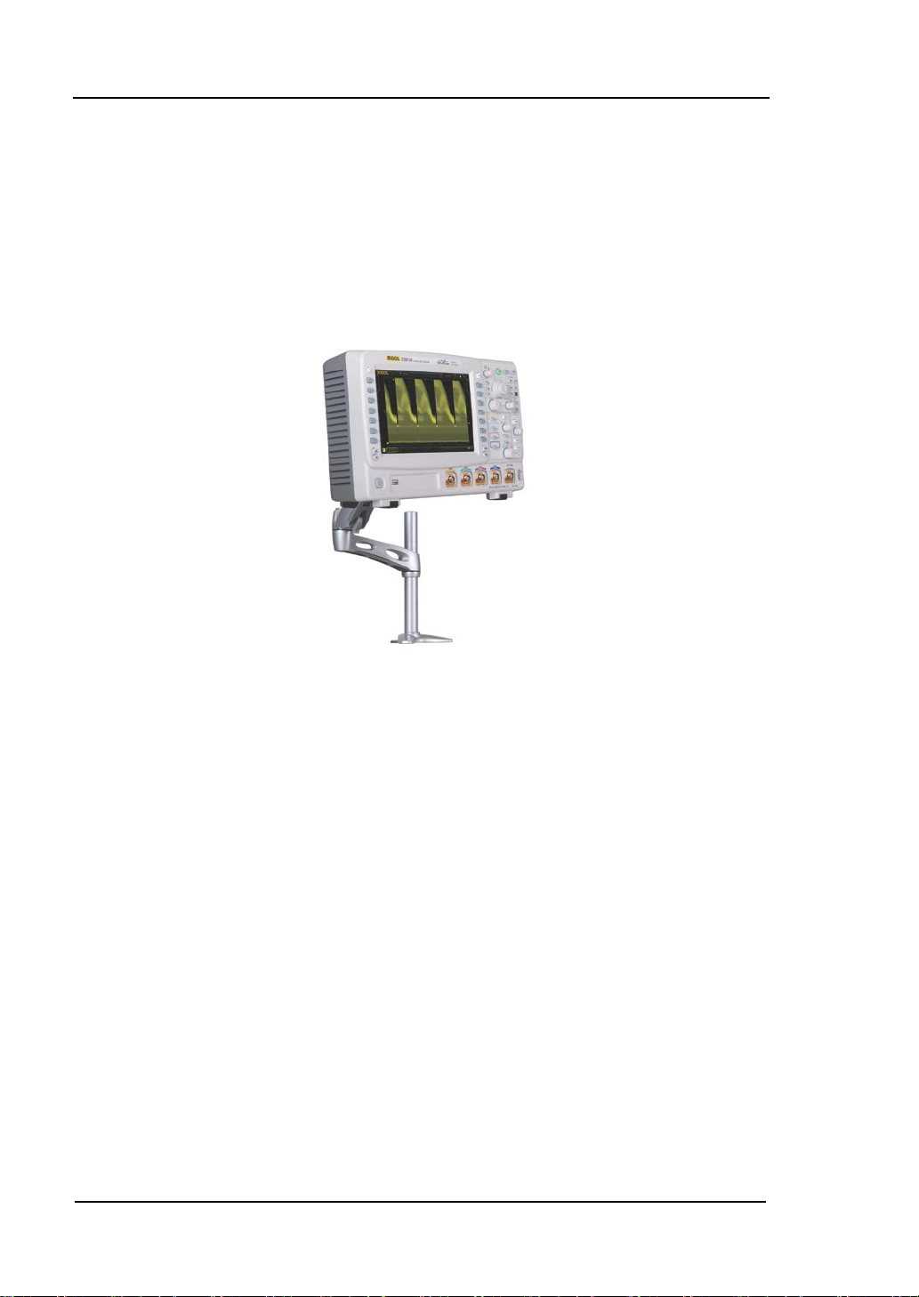
To Use the Desk Mount Instrument Arm
Using an arm, the oscilloscope could be mounted on the workbench to save your
operation space. The height and angle of the instrument co uld be adjusted freely to
acquire supreme comfort and efficiency and to convenient your measurement and
observation. If needed, please buy and install the corresponding option.
Figure 1-15 Working Sketch of the Instrument with the Instrument Arm
DS6000 User’s Guide
Page 53
1 Quick Start RIGOL
1-31
To Use the Rack Mount Kit
This oscilloscope can be mounted in a standard 19-inch rack cabi net that conforms to
the Electric Industrial Association (EIA) standard. If needed, please buy and install
the corresponding option.
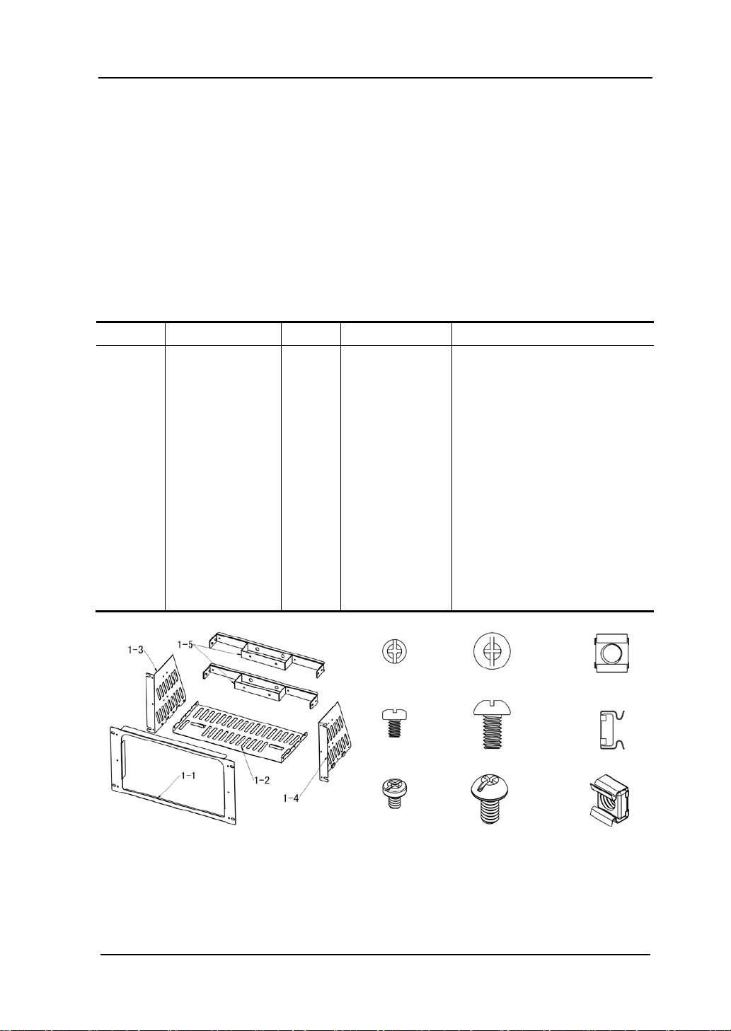
Kit Parts List
No. Name Qty Part No. Description
1-1 Front Plate 1 RM-DS-6-01
1-2 Support Board 1 RM-DS-6-02
1-3 Left Plate 1 RM-DS-6-03
1-4 Right Plate 1 RM-DS-6-04
1-5 Back Batten 2 RM-DS-6-05
2-1 M4 Screw 24 RM-SCREW-01 M4 x 6 Phil-Slot Pan Head
Machine Screw Nail
2-2 M6 Screw 4 RM-SCREW-02 M6 x 16 Phil-Slot Pan Head
Machine Screw Nail
2-3 M6 Nut 4 RM-SCREW-03 M6 x 5 Square Machine
Female Screw Contain Lock
Blade
2-1 2-2 2-3
DS6000 User’s Guide
Page 54
RIGOL 1 Quick Start
1-32
Installation Tool
PH2 Phillips Screwdriver (recommended).
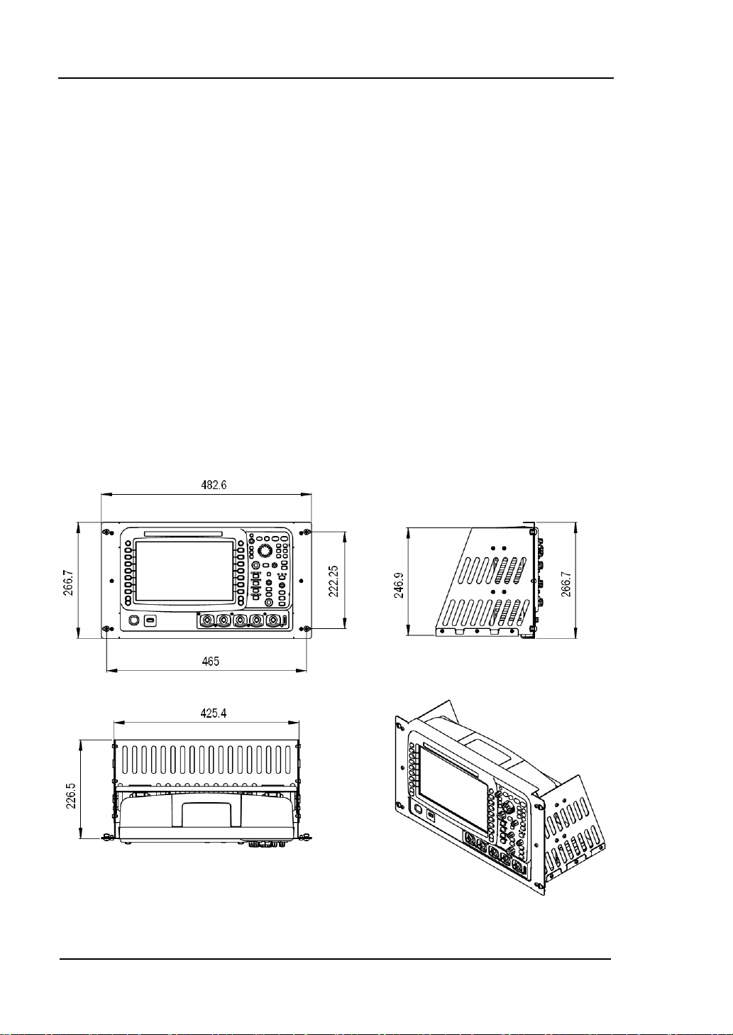
Installation Space
The following requirements must be fulfilled by the machine cabinet in which the
instrument is mounted.
The machine cabinet must be a standard 19-inch one.
At least 6U (266.7 mm) height should be provided by the machine cabinet.
The depth inside the machine cabinet should not be less than 400 mm.
The dimension of the instrument after being installed is shown below (the unit is
mm).
DS6000 User’s Guide
Page 55
1 Quick Start RIGOL
1-33
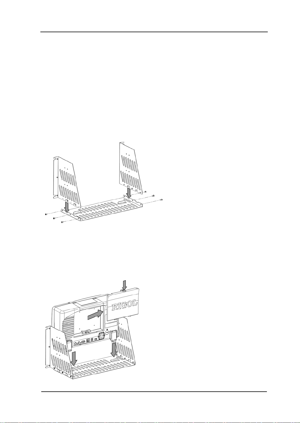
Installation Procedures
Only authorized operators can execute the installation operation. Improper
installation might result in damage of the instrument or incorrect installation of the
instrument on the rack.
1. Install the right and left plates: align the detents of the right and left plates with
the openings on the support board and insert them into the support board
respectively, then fix them with six M4 screws.
2. Place the Instrument: press the button above the battery on the instrument to
remove the battery. Then align the instrument with the spacing on the support
board and place it on the support board.
DS6000 User’s Guide
Page 56
RIGOL 1 Quick Start
1-34
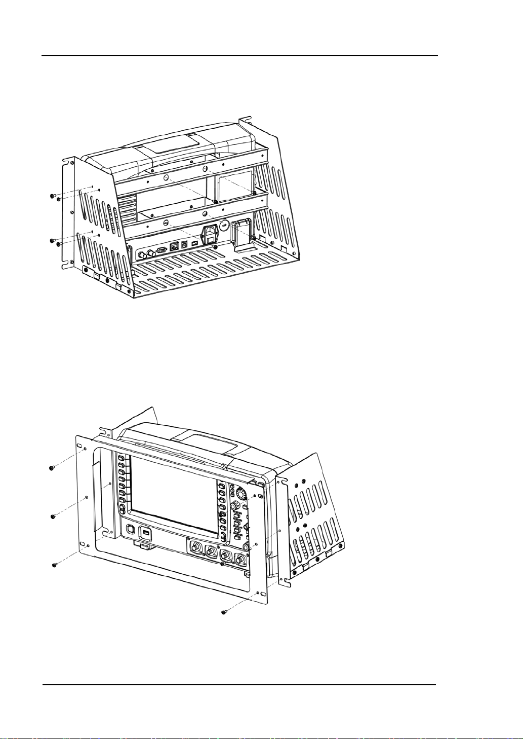
3. Fix the instrument: fix the instrument onto the support board with two back
battens and twelve M4 screws.
4. Install the front plate: align the screw holes on the right and left plates with the
screw holes on the front plate of the rack and let the front panel of the
oscilloscope protrude from the opening. Then fix them with six M4 screws.
DS6000 User’s Guide
Page 57

1 Quick Start RIGOL
1-35
5. Load into the machine cabinet: mount the rack with the instrument fixed to it
into a standard 19-inch machine cabinet with fo ur M6 screws and four M6 square
nuts.
6. Post-installation notice: the rack occupies a height of 6U. The holes pointed out
by the arrows are installation holes. Note that they s hould be aligned with during
installation.
DS6000 User’s Guide
Page 58

RIGOL 1 Quick Start
1-36
To Use the Built-in Help System
The help system of this oscilloscope provides instructions for all the function keys
(including menu keys) at the front panel. Press HELP to open the help interface and
press again to close the interface. The help interface mainly consists of two parts.
The left is “Help Options” and you can use “Button” or “Index” to select. The r ig ht is
“Help Display Area”.
Help Options Help Display Area
Figure 1-16 Help Information
Button:
Default mode. In this mode, you can press the buttons (except the power key
the knob
and menu page up/ down key / ) or rotate the Navigation knob
,
at the front panel directly to get the corr esponding help inf ormatio n of that button in
the “Help Display Area”.
Use
to select “To Index” and then press the knob to switch to Index mode.
Index:
In this mode, use
to select the item that needs to get help (for example: “Band
Width”). Press the knob to get the corresponding help information in the “Help
Display Area”.
Use
to select “To Button” and then press the knob to switch to Button mode.
DS6000 User’s Guide
Page 59

2 To Set the Vertical System RIGOL
2-1
2 To Set the Vertical System
The contents of this chapter:
To Enable the Channel
Channel Coupling
Bandwidth Limit
Probe
Input Impedance
Waveform Invert
Vertical Scale
Vertical Expansion
Amplitude Unit
Channel Label
Delay Calibration
DS6000 User’s Guide
Page 60

RIGOL 2 To Set the Vertical System
2-2
To Enable the Channel
DS6000 provides four analog input channels (CH1-CH4) and each channel can be
controlled independently.
CH1
Connect a signal to the channel connector of any channel (for example, CH1) and
then press CH1 in the vertical control area (VERTICAL) at the front panel to enable
CH1. At this point:
Panel:
The backlight of this key turns on. If the corresponding function in this menu has
been turned on, the characters “AC”, “50” or “BW” might also be illuminated. Note:
the on/off state of the key light of “AC”, “50” or “BW” is not limited by the on/off state
of the channel.
Screen:
The channel setting menu is d isplayed at the right side of the screen and the chan nel
label at the bottom of the screen (as shown in the figure below) is highlighted. The
information displayed in the channel label is related to the current channel setting.
After the channel is turned on, modif y the parameters such as the vertical scale, the
horizontal time base and the trigger mode according to the input signal to mak e the
waveform display easy to observe and measure.
DS6000 User’s Guide
Page 61

2 To Set the Vertical System RIGOL
2-3
Channel Coupling
Set the coupling mode to filter out the signals that is not needed. For example, the
signal under test is a square waveform with DC offset.
When the coupling mode is “DC”: the DC and AC components of the signal under
test can both pass the channel.
When the coupling mode is “AC”: the DC components of the signal under test
are blocked.
When the coupling mode is “GND”: the DC and AC components of the signal
under test are both blocked.
Press CH1 Coupling and use to select the desired coupling mode (the
default is DC). The current coupling mode is displayed in the channel label at the
bottom of the screen. When “AC” is selected, the character “AC” above the CH1
channel key at the front panel will be illuminated. You can also press Coupling
continuously to switch the coupling mode.
DS6000 User’s Guide
Page 62

RIGOL 2 To Set the Vertical System
2-4
Bandwidth Limit
Set the bandwidth to reduce the display noise. For example, the signal under test is a
pulse signal with high frequency oscillation.
When the bandwidth limit is turned off, the high frequency components of the
signal under test can pass the channel.
Turn on the bandwidth limit and limit it to 20 MHz or 250 MHz, the high
frequency components that exceed 20 MHz or 250 MHz are attenuated.
Press CH1 BW Limit and use to turn on/off the bandwidth limit (t he default
is off). When the bandwidth limit (20 MHz or 250 MHz) is turned on, the character
“B” will be displayed in the channel label at the bottom of the screen. You can also
press BW Limit continuously to switch between on and off of the bandwidth limit.
Probe
This oscilloscope supports normal passive probe and active differ ential probe and can
automatically identify the type of the probe currently connected and the probe r atio .
Press CH1 Probe to turn on the probe operation menu.
1. ProbeType
Read the type of the probe currently connected as “Nor-Probe” or “DiffProbe”.
Note that when using a 50 Ω “DiffProbe”, the Input Impedance of the channel
is set to “50Ω” automatically.
Normal Probe: such as RP5600, RP3500 and RP6150 of RIGOL.
Differential Probe: such as RP7150 of RIGOL.
2. Ratio
The oscilloscope can identify the probe ratio automatically. If the oscilloscope can
not identify , press this softkey to select the corresponding probe ratio. The probe
ratio can be the values listed in the table on the next page.
DS6000 User’s Guide
Page 63

2 To Set the Vertical System RIGOL
2-5
0.01X
1000 X
1:100
1000:1
Table 2-1 Probe Attenuation Coefficient
Menu Attenuation coefficient
0.02X
0.05X
0.1X
0.2X
0.5X
1X
2X
5X
10X
20 X
50 X
100 X
200 X
500 X
1:50
1:20
1:10
1:5
1:2
1:1
2:1
5:1
10:1
20:1
50:1
100:1
200:1
500:1
When “DiffProbe” is inserted, the oscilloscope recognizes it automatically and the
following menus are added.
3. Front-End
RP7150 active probe provides “Single-end” and “Difference” pr obe heads. Press
this softkey to select the desired probe head.
4. Probe-Cal
Connect the differential probe to the channel input terminal ( such as CH1) of the
oscilloscope correctly, then connect the fast edge signal output from the [Trig
Out/Calibration] connector at the rear panel of the instrument to the probe
and CH2 respectively. At this point, press this softkey and the oscilloscope starts
to calibrate the probe.
Note: if the probe is connected to CH1, CH3 or CH4, the fast edge signal should
be connected to CH2; if the probe is connected to CH2, the fast edge signal
should be connected to CH1.
5. Probe Info
Press this softkey to view various information about the probe, such as the
manufacturer, model, serial number and the date of last calibration.
DS6000 User’s Guide
Page 64

RIGOL 2 To Set the Vertical System
2-6
6. Bias Voltage
The oscilloscope provides bias voltage for differential probe. This bias voltage is
used to adjust the signal under test that exceeds the input dynamic range of the
probe amplifier to an appropriate range to ensure the completeness of the
signal under test. Press this softkey and use the knob to adjust the bias voltag e.
The range is from -12V to +12V.
DS6000 User’s Guide
Page 65
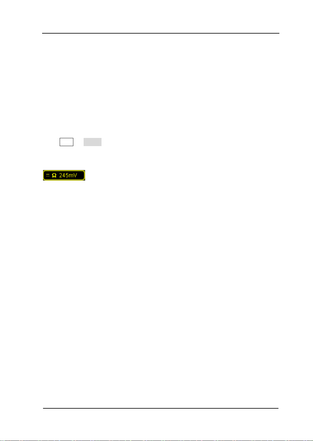
2 To Set the Vertical System RIGOL
2-7
Input Impedance
To reduce the circuit load caused by the interaction of the oscilloscope and the circuit
under test, this oscilloscope provides two input impedance modes: 1 MΩ (default)
and 50 Ω.
1 MΩ: at this point, the input impedance of the oscilloscope is very high and the
current flows into the oscilloscope from the circuit under test can be ignored.
50 Ω: match the oscilloscope with devices whose output impedance is 50 Ω.
Press CH1 Input to set the input impedance of the oscilloscope. When “50 Ω” is
selected, the character “Ω” is displayed in the channel label at the bottom of the
screen.
Note: after the probe is automatically identified, the input impedance will be
automatically identified and you do not need to set it manually.
DS6000 User’s Guide
Page 66
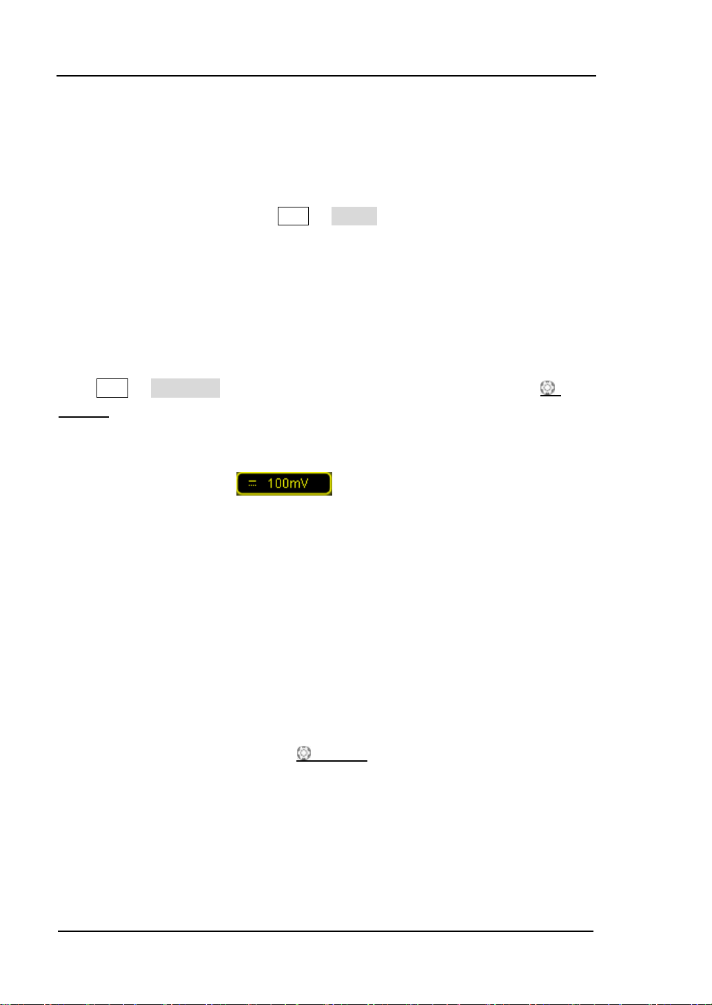
RIGOL 2 To Set the Vertical System
2-8
Waveform Invert
When waveform invert is turned on, the waveform display rotates 180 degree
relative to the ground potential. When the waveform invert is turned off, the
waveform display is normal. Press CH1 Invert to tur n waveform invert on or off.
Vertical Scale
The vertical scale adjustment has two modes: “Coarse” and “Fine”.
Press CH1 Volts/Div to select the desired mode. Turn the VERTICAL
SCALE to adjust the vertical scale. Turn clockwise to reduce the scale and turn
counterclockwise to increase the scale.
The scale information (e.g.
screen will change accordingly during the adjustment. The adjustable range of the
vertical scale is related to the current probe ratio. By default, the probe attenuation
ratio is 1X and the adjustable range of the vertical scale is from 2 mV/div to 5 V/div.
Coarse adjustment (take counterclockwise as an example): set the vertical scale
in 1-2-5 step namely 2 mV/div, 5 mV/div, 10 mV/div…5 V/div.
Fine adjustment: further adjust the vertical scale within a relatively smaller
range to improve vertical resolution. If the am plitude of the input waveform is a
little bit greater than the f ull scale and the amplitude woul d be a little bit lower if
the next scale is used, fine adjustment can be use d to impr ov e the a mplitude of
waveform display to view the details of the signal.
Note: you can also press VERTICAL
fine adjustments.
) in the channel label at the bo ttom of the
SCALE to quickly switch between corse and
DS6000 User’s Guide
Page 67

2 To Set the Vertical System RIGOL
2-9
Vertical Expansion
When using VERTICAL
channel, you can choose to expand or compress the vertical signal around the center
of the screen or around the ground point of the signal.
Press UTIL System VerticalExp to select “Center” or “Ground” and the
default is “Ground”.
Center: when the vertical scale is changed, the waveform will expand or
compress around the center of the screen.
Ground: when the vertical scale is changed, the waveform ground level will
remain at the same point on the screen and the waveform will expand or
compress around this point.
SCALE to change the vertical scale of the analog
Amplitude Unit
Select the amplitude display unit for t he current channel. The available units are W, A,
V and U. when the unit is changed, the unit in the channel label will change
accordingly.
Press CH1 Unit to select the desired unit and the default is V.
DS6000 User’s Guide
Page 68
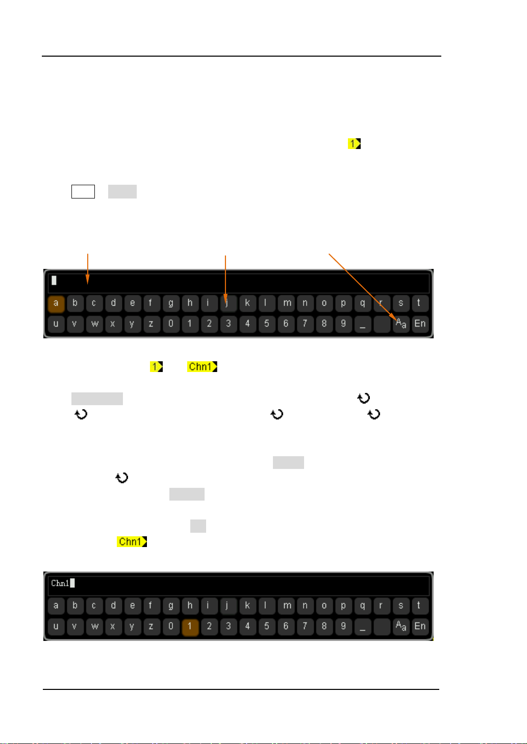
RIGOL 2 To Set the Vertical System
2-10
Channel Label
You can modif y the labels used to mark the analog channels (CH1 to CH4) at the left
side of the screen. The label is the number of the channel (e.g.
the length of the modified label can not exceed 4 characters.
Press CH1 Label to enter the label modification interface. As shown in the figure
below:
Name Input Area Keyboard Upper-lower Case Switch
) by default and
For example, change “
” to “ ”.
Press Keyboard to select the “Keyboard” area. Select “Aa” using and press
down
to switch it to “aA”. Select “C” using and press down to input the
character. Use the same method to input “hn1”.
To modify or delete the inputed character, press Name to select the “Name Input
Area” and use
to select the character to be modified or deleted. Reenter the
desired character or press Delete to delete the selected character.
After finishing the input, press OK to finish the modification and the channel label
will change to “
”.
DS6000 User’s Guide
Page 69
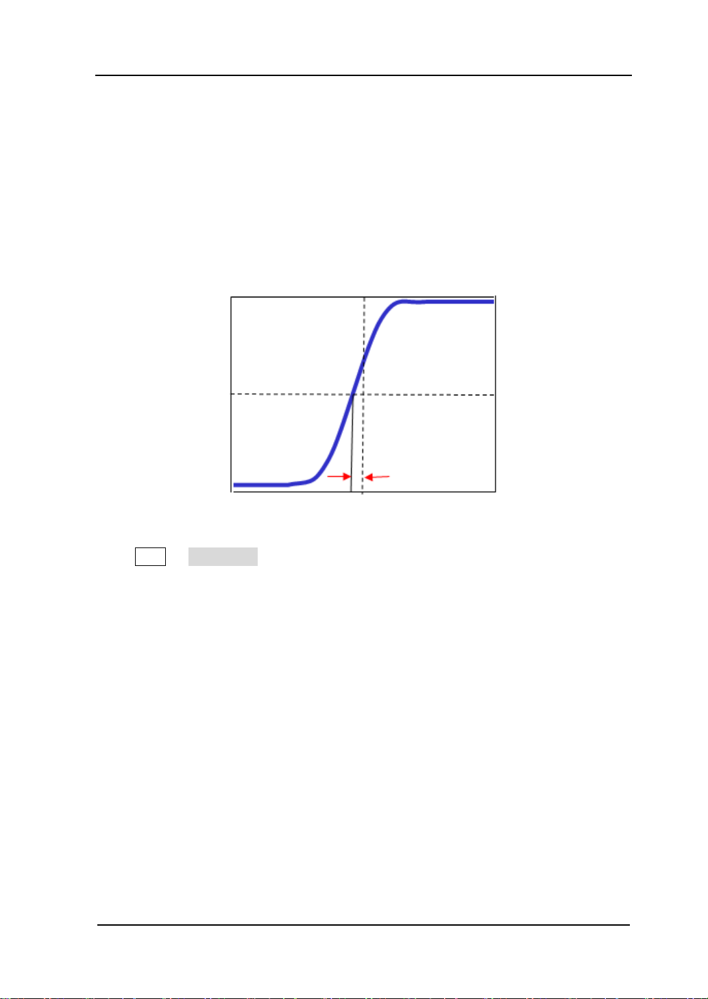
2 To Set the Vertical System RIGOL
2-11
Zero Point Offset
Delay Calibration
When using the oscilloscope for actual measurement, the transmission delay of the
probe cable may bring relatively larger error (zero point offset). For DS6000, users
can set a delay time to calibrate the zero point offset of the corresponding channel.
Zero point offset is defined as the offset of the crossing of the wavef orm and trigger
level line relative to the trigger position as shown in the figure below.
Trigger Position
Trigger Level
Press CH1 Delay-Cal and use the knob to set the desired delay time. The range
is from -100 ns to 100 ns.
Note: this parameter is related to the horizontal time base currently set. F or example,
when the horizontal time base is 5 μs, the step of delay time setting is 100 ns; when
the horizontal time base is 1 μs, the step of delay time setting is 20 ns; when the
horizontal time base is 500 ns, the step of delay time setting is 10 ns.
DS6000 User’s Guide
Page 70

Page 71

3 To Set the Horizontal System RIGOL
3-1
3 To Set the Horizontal System
The contents of this chapter:
Delayed Sweep
Time Base Mode
Horizontal Scale
Horizontal Reference
DS6000 User’s Guide
Page 72

RIGOL 3 To Set the Horizontal System
3-2
Main time
Delayed Sweep
Delayed sweep can be used to enlar ge a length of w av eform horiz ontally to vie w the
details of the image.
MENU
Press MENU in the horizontal control area (HORIZONTAL) and then press Delayed
to turn the delayed swee p on or off. Note: to enable delayed sweep, the current time
base mode must be “Y-T” and the “Pass/Fail test” must be disabled.
In delayed sweep mode, the screen is divided into two display areas as shown in the
figure below.
The waveform before
enlargement
Delaye
Sweep
Time
Base
base
延迟扫描时基
The waveform after enlargement
DS6000 User’s Guide
Page 73

3 To Set the Horizontal System RIGOL
3-3
Tip
The waveform before enlargement:
The waveform in the area that has not been covered by the subtransparent blue in
the upper part of the screen is the waveform before enlargement. You can turn
HORIZONTAL
HORIZONTAL
POSITION to move the area left and right or turn
SCALE to enlarge or reduce this area.
The waveform after enlargement:
The waveform in the lower part of the screen is the horizontally expanded wav eform.
Note: the delayed time base has increased its resolution relative to the main time
base (as shown in the figure above). The delayed time base should be less than or
equal to the main time base.
When the channel is currently CH1-CH4, you can enter the delayed sweep not only
through MENU operation in the horizontal area but also by directly pressing
HORIZONTAL SCALE (delayed sweep shortcut key) to switch to the delayed
sweep mode.
DS6000 User’s Guide
Page 74

RIGOL 3 To Set the Horizontal System
3-4
Time Base Mode
Press MENU in the horizontal control area at the front panel and then press Time
Base to select the time base mode of the oscilloscope and the default is Y-T mode.
Y-T Mode
This mode is the main time base mode and is applicable to CH1-CH4 input channels.
In this mode, the Y axis represents voltage and the X axis represents time. Note: only
when this mode is enabled can “Delayed Sweep” be turned on.
DS6000 User’s Guide
Page 75

3 To Set the Horizontal System RIGOL
3-5
The signal must be
X-Y Mode
In this mode, the oscilloscope automatically turns on all the four channels (CH 1-CH4)
and the screen is divided into two coordinate areas, where, X1 and Y1 track the
voltages of CH2 and CH1 and X2 and Y2 track the voltages of CH4 and CH3.
The phase deviation of two signals with the same frequency can be easily measured
via Lissajous method. The figure below shows the measurement schematic diagram
of the phase deviation.
centered horizontally
D
II I
II I
C
III IV
III IV
A
B
According to sin
two channels and the definitions of A, B, C and D are as shown in the figure above),
the phase deviation angle is obtained, that is:
If the principal axis of the ellipse is within the quadrants of I and III, the phase
deviation angle obtained should be within the quadrants of I and IV namely within
(0~π/2) or (3π/2~2π). If the principal axis of the ellips e is within the quadr ants of II
and IV, the phase deviation angle obtained should be within the quadrants of II and
III namely within (π/2~π) or (π~3π/2).
DS6000 User’s Guide
θ=A/B or C/D (where, θ is the phase deviation angle between the
θ=±arcsin (A/B) or ±arcsin (C/D)
Page 76

RIGOL 3 To Set the Horizontal System
3-6
X-Y function can be used to measure the phase deviation occurred when the test
signal passes through a circuit network. Connect the oscilloscope to the circuit to
monitor the input and output signals of the circuit.
Application example:
Measure the phase deviation of the input signals of two channels.
Method 1: Use Lissajous method
1. Connect a sine signal to CH1 and then connect a sine signal with the same
frequency and amplitude but a 90° phase deviation to CH2.
2. Press Auto, turn on the X-Y mode and rotate HORIZONTAL
SCALE to
adjust the sample rate properly to get a better Lissajous figure for better
observation and measurement.
3. Adjust VERTICAL POSITION of CH1 and CH2 to display the signals at the
center of the coordinate region and adjust VERTICAL
SCALE of CH1 and
CH2 to make the signals easy to observe. At this point, the circle as shown in the
figure below should be got.
4. From the figure above, the distances from the points of intersection of the X/Y
axis and the circle to the origin of the coordinates are approximately equal. Thus,
the phase deviation angle
θ=±arcsin1=90°.
DS6000 User’s Guide
Page 77

3 To Set the Horizontal System RIGOL
3-7
Note:
In Y-T mode, the oscilloscope could use arbitrary sample rate (within the
guaranteed range) to capture waveform. The maximum sample rate of Y-T
mode is 2.5 GSa/s. Generally, reducing the sample rate properly could get a
Lissajous figure with relatively better display effect.
When X-Y mode is turned on, “Delayed” will be turned off automatically.
The following functions are not available in X-Y mode:
Auto measure, cursor measure, math operation, delayed sweep, vector display
type, HORIZONTAL
POSITION, trigger control, memory depth,
acquisition mode, Pass/Fail test and waveform recording.
Method 2: Use the shortcut measurement function
Please refer to “Phase A→B ” and “Phase A→B ” measurement functions of “Delay
and Phase” on page 6-17.
DS6000 User’s Guide
Page 78

RIGOL 3 To Set the Horizontal System
3-8
Slow Sweep
Roll Mode
In this mode, the waveform scrolls f rom the right to the left to update the displa y and
the waveform horizontal position and trigger control are not available. The range of
horizontal scale adjustment is from 200.0 ms to 1.000 ks.
Note: when Roll mode is turned on, “Delayed Sweep”, “Protocol Decoding”,
“Pass/Fail Test”, “Measurement Range”, “Waveform Recording”, “To Set
the Persistence Time” and “To Trigger the Oscilloscope” are not available.
Another mode similar to the Roll mode. When the horizontal time base is set to 200
ms/div or slower, the instrument enters the “slow sweep” mode in which the
instrument f irst acquires the data at the left of the trigger point and then waits for
trigger event. After the trigger occurred, the instrument continues to finish the
waveform at the right of the trigger point. When using the slow sweep mode to
observe low frequency signal, it is recommended that the Channel Coupling is set
to “DC”.
DS6000 User’s Guide
Page 79

3 To Set the Horizontal System RIGOL
3-9
Horizontal Scale
Being similar to “Vertical Scale
“Coarse” and “Fine”.
Press MENU ScaleAdjust in the horizontal control area (HORIZONTAL) at the
front panel to select the desired mode. Turn HORIZONTAL SCALE to adjust the
horizontal scale. Turn clockwise to reduce the horizontal scale and turn
counterclockwise to increase the scale.
The scale information (e.g.
change accordingly during the adjustment. The range of horizontal scale adjustment
is from 500 ps to 1.000 ks.
Coarse (take counterclockwise as an example): set the horizontal scale in 1-2-5
step namely 500 ps, 1 ns, 2 ns, 5 ns…1.000 ks.
Fine: further adjust within smaller range.
”, the horizontal scale adjustment has two modes:
) at the upper left corner of the screen will
DS6000 User’s Guide
Page 80
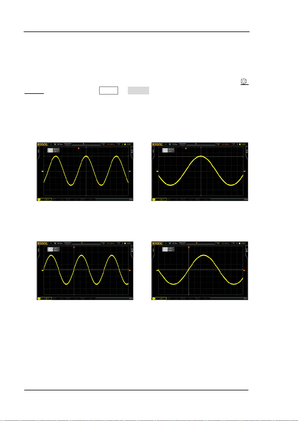
RIGOL 3 To Set the Horizontal System
3-10
Horizontal Reference
Horizontal reference is the reference position according to which the screen
waveform expands and compresses horizontally when adjusting HORIZONTAL
SCALE. In Y-T mode, press MENU HorRef in the horizontal control area
(HORIZONTAL) to select the desired reference mode and the default is “Center”.
1. The Center of the Screen
When changing the horizontal time base, the wa veform expands or compresses
horizontally around the center of the screen.
2. Trigger Position
When changing the horizontal time base, the w av ef orm expa nds or compresses
horizontally around the trigger point.
3. User-defined
When changing the horizontal time base, the wa veform expands or compresses
horizontally around the user-defined reference position (after selectin g “User”,
use the knob to set the reference position and the range is from -350 to 350). In
the horizontal direction, the screen can display a maximum of 700 points with
the leftmost as 350 and the rightmost as -350. For example: set the reference
position to 150:
DS6000 User’s Guide
Page 81
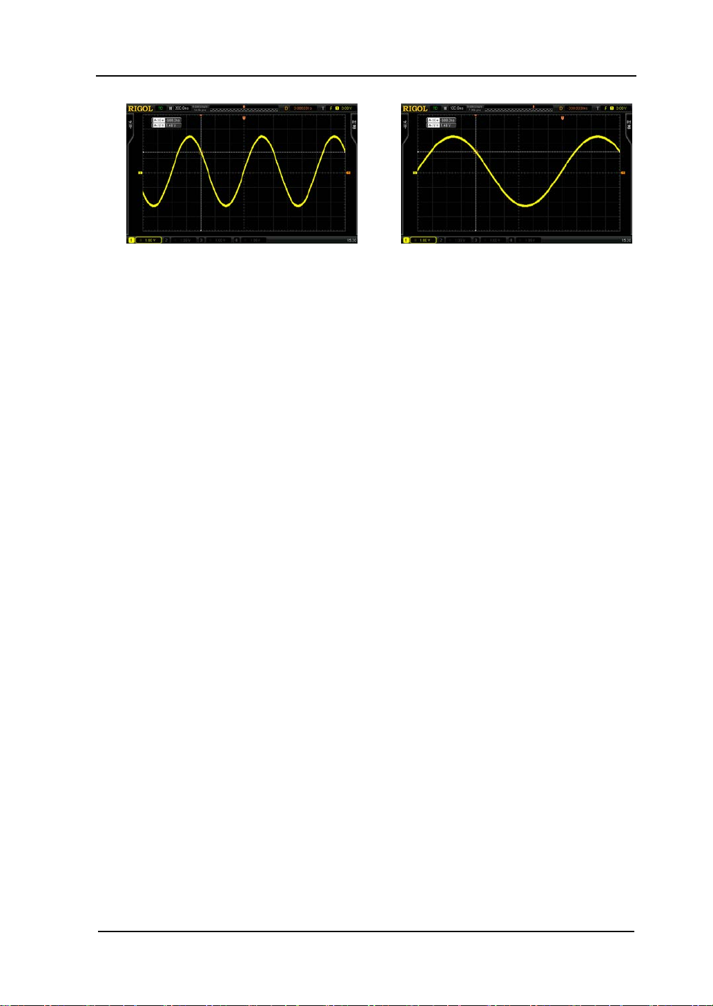
3 To Set the Horizontal System RIGOL
3-11
DS6000 User’s Guide
Page 82

Page 83

4 To Set the Sample System RIGOL
4-1
4 To Set the Sample System
The contents of this chapter:
Acquisition Mode
Sample Mode
Sample Rate
Memory Depth
Antialiasing
DS6000 User’s Guide
Page 84
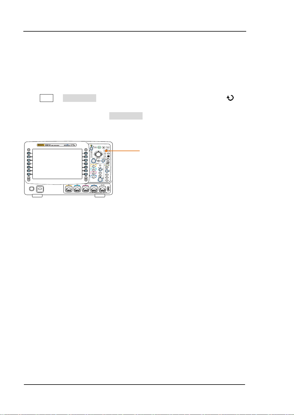
RIGOL 4 To Set the Sample System
4-2
Acquisition Mode
The acquisition mode is used to control h ow to generate waveform poi nts from the
sample points.
Press ACQ Acquisition in the function menu at the front panel and use to
select the desired acquisition mode (the default is normal), then press the knob to
select this mode. You can press Acquisition continuously to switch the acquisition
mode.
ACQ
Normal
In this mode, the oscilloscope samples the signal at equal time interval to r ebuild the
waveform. For most of the waveforms, the best display effect is generated by using
this mode.
Average
In this mode, the oscilloscope averages the waveforms from multiple samples to
reduce the random noi se of the input signal and im pr ov e the v er tical r esoluti on. The
higher the number of aver ages is, the lower is the noise and the highe r is the vertical
resolution but the slower is the response of the displayed wa veform to the w avef orm
changes.
DS6000 User’s Guide
Page 85
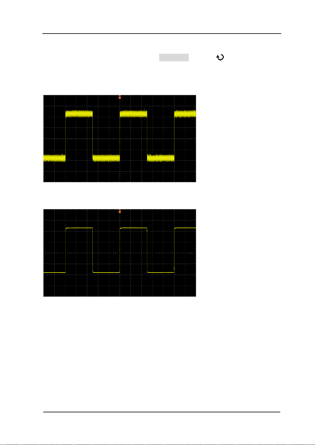
4 To Set the Sample System RIGOL
4-3
The available range of the n umber of av erages i s from 2 to 8192 and the default i s 2.
When “Average” mode is selected, press Averages and use to set the desired
number of averages as the power function of 2.
The Waveform before Average:
The Waveform after 256 Averages:
DS6000 User’s Guide
Page 86

RIGOL 4 To Set the Sample System
4-4
Peak Detect
In this mode, the oscilloscope acquires the maximum and minimum values of the
sample interval signal to get the envelope or the narrow pulse of the signal that
might be lost. Use this mode to avoid signal confusion at the expense of
exaggerating the noise.
In this mode, the oscilloscope can display all the pulses whose pulse widths are at
least as wide as the sample period.
High Resolution
This mode uses a kind of ultra-sample technique to average the neighboring points
of the sample waveform to reduce the random noise on the input signal and generate
much smoother waveforms on the screen. This is generally used when the sample
rate of the digital converter is higher than the save rate of the acquisition memory.
Note: “Average” and “High Res” modes use different averag ing methods. The former
uses “Waveform Average” and the latter uses “Dot Average”.
DS6000 User’s Guide
Page 87
4 To Set the Sample System RIGOL
4-5
Tip
Sample Mode
Press ACQ Sampling and press this softkey continuously to switch the sample
mode (the default is real-time sample). Note: all the “Acquisition Mode” support
real-time sample and equivalent sample.
Real-time Sample
In this mode, the oscilloscope samples and displays waveform within a trigger event.
The maximum real-time sample rate of DS6000 is 5 GSa/s and the current sample
rate is displayed under the Sa Rate menu.
Equivalent Sample
In this mode, the oscilloscope performs multiple trigger samples, samples at
different positions of each trigger and uses the sample points from multiple triggers
to rebuild the signal. The equivalent sample mode helps with detailed observation of
the repeated periodic signals. The maximum equivalent sample rate of DS6000 is
100 GSa/s.
Press Run/Stop to stop the sample, the oscilloscope will hold the last display. At
this point, you can still use the vertical control and horizontal control to pan and
zoom the waveform.
DS6000 User’s Guide
Page 88
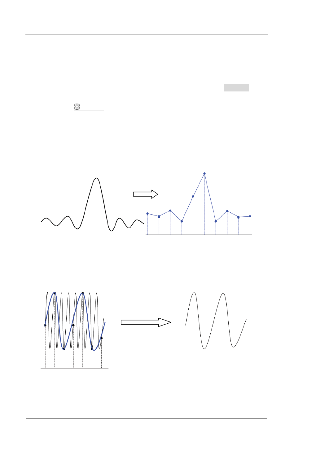
RIGOL 4 To Set the Sample System
4-6
Sample Rate
The sample rate of this oscilloscope is up to 5 GSa/s. Note: the sample rate is
displayed in the sta tus ba r at the up per side of the screen and in the Sa Rate menu
and can be changed by adjusting the horizontal time base (s/div) through
HORIZONTAL
The influence on the waveform when the sample rate is too low:
1. Waveform Distortion: when the sample rate is too low, some waveform
details are lost and the waveform displayed is rather different from the actual
signal.
SCALE or modifying the “Mem Depth”.
2. Waveform Aliasing: when the sample rate is lower than twice the actual
signal frequency (Nyquist Fr equency ), the frequency of the waveform rebuilt by
the sample data is lower than the actual signal frequency. The most common
aliasing is the jitter on a fast edge.
DS6000 User’s Guide
Page 89
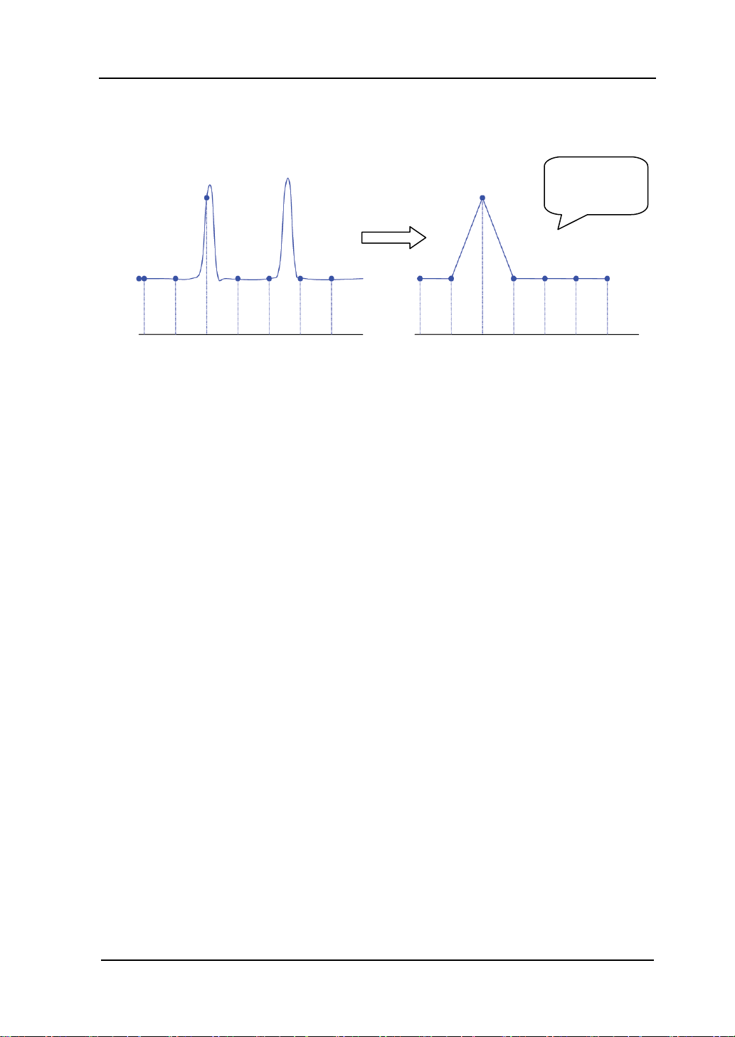
4 To Set the Sample System RIGOL
4-7
3. Waveform Leakage: when the sample rate is too low , the wav eform rebuilt by
the sample data does not reflect all the actual signal information.
Pulse
disappeared
DS6000 User’s Guide
Page 90

RIGOL 4 To Set the Sample System
4-8
T
Trigger Point
Pre-sample
Delayed Sample
Memory Depth
Memory Depth
Memory depth refers to the number of waveform points that the oscilloscope can
store in a single trigger sample and it reflects the storage ability of the acquisition
memory. DS6000 provides a memory depth up to 140 M points.
The relationship of memory depth, sample rate and waveform length fulfills the
following equation:
Memory depth = sample rate (Sa/s) × waveform length (s/div × div)
Press ACQ Mem Depth, use to select the desired memory depth (the default
is auto) and then press the knob to select the option. You can also press Mem
Depth continuously to switch the memory depth.
When single channel is turned on, the memory depths available include Auto,
14kPoints, 140kPoints, 1.4MPoints, 14MPoints and 140MPoints. In “Auto” mode, th e
oscilloscope selects the memory depth automatically according to the current sample
rate.
When double channels are turned on (CH1 and CH2 or CH3 and CH4), the memory
depths available include Auto, 7kPoints, 70kPoints, 700kPoints, 7MPoints and
70MPoints. In “Auto” mode, the oscilloscope selects the memory depth automatically
according to the current sample rate.
DS6000 User’s Guide
Page 91

4 To Set the Sample System RIGOL
4-9
Antialiasing
At slower sweep speeds, the sample rate is reduced and a proprietary display
algorithm is used to minimize the likelihood of aliasing.
Press ACQ Anti-aliasing to turn on or off the antialiasing function. By default,
Antialiasing is disabled. The displayed wavef orms will be more susceptible to aliasing
when this function is disabled.
DS6000 User’s Guide
Page 92

Page 93

5 To Trigger the Oscilloscope RIGOL
5-1
5 To Trigger the Oscilloscope
For trigger, you set certain trigger condition according to the requirement and when
a waveform in the waveform stream meets this condition, the oscilloscope captures
this waveform as well as the neighbouring part and displays them on the screen.
When working, the digital oscilloscope continuously acquires wav eform data even if a
valid trigger does not occur. However, only when valid triggers occur, can the display
become stable. The trigger circuit guarantees that each sweep or sample starts from
the position of the trigger event in the input signal, namely each sweep and sample
are synchronous and the waveforms acquired overlap to display stable waveform.
Trigger setting should be based o n the features of the input signal, thus you need to
have some knowledge of the signal under test to quickly capture the desired
waveform. This oscilloscope provides abundant advanced trigger functions which
help you to focus on the waveform details of interest.
The contents of this chapter:
Trigger Source
Trigger Mode
Trigger Coupling
Trigger Holdoff
Trigger Type
Trigger Ouput Connector
DS6000 User’s Guide
Page 94

RIGOL 5 To Trigger the Oscilloscope
5-2
Trigger Source
Press MENU Source in the trigger control area (TRIGGER) at the front panel to
select the desired trigger source. Signals input from the analog channels CH1-CH4
and the [EXT TRIG] connector as well as the AC Li ne ca n all be used as the trigger
source.
MENU
Analog channel input:
Signals input from analog channels CH1-CH4 can all be used as the trigger source.
No matter whether the input from the channel selected is displayed, the cha nnel can
work normally.
External trigger input:
External trigger can be used to trigger on the fifth channel at the same time when all
the four channels are acqu iring data. The trigger sig nal (e.g. external clock, signal of
the circuit to be tested) will be connected to EXT or EXT/5 trigger source via the
[EXT TRIG] connector. You can set the trigger conditions within the range of the
trigger level from -0.8 V to +0.8 V.
AC Line:
The trigger signals are obtained from the AC power input of the oscilloscope. This
kind of signals can be used to display the relationship between signal (such as
illuminating device) and power (power supply device). For example, to stably trigger
the waveform output from the transformer of a transformer substation, which is
mainly used in related measurement of the power industry.
DS6000 User’s Guide
Page 95

5 To Trigger the Oscilloscope RIGOL
5-3
Trigger Mode
T rigger mode would influence the mode in which the oscilloscope searches for trigger
event. The following is the schematic diagram of the acquisition memory from which
you can see that the position of the trigger event is determined by the reference time
point and the delay setting.
Pre-trigger Buffer Post-trigger Buffer
Acquisition memory
Pre-trigger/ Delayed trigger:
Acquire data before/after the trigger event. The trigger position is usually at the
horizontal center of the screen. In full-screen display, you can view seven-grid
pre-trigger and delayed trigger information. You can adjust the horizontal position of
the waveform through HORIZONTAL
information and delayed trigger information, through which to know the signal
information before/after the trigger (e.g. capture the glitch generated by the circuit
and analyze the pre-trigger data to find out the reasons for generating glitch).
Press MODE in the trigger contr ol are a (TRIGGER) at the f ront panel or thro ugh the
MENU Mode menu to select the desired trigger mode. The corresponding status
light of the mode currently selected turns on.
Trigger Event
POSITION
to view more pre-trigger
MODE
DS6000 User’s Guide
Page 96

RIGOL 5 To Trigger the Oscilloscope
5-4
Auto:
No matter whether the trigger condition is met, there is always waveform display. A
horizontal line is displayed when no signal is input.
When this mode is selected, the oscilloscope fills the pre-trigger buffer first and then
search for a trigger while at the same time continues filling data. When the
oscilloscope is searching for trigger, the data firstly filled into the pre-trigger buffer
will overflow and be pushed out of the FIFO queue. When a trigger is found, the
pre-trigger buffer would contain the data acq ui red before the trigger. If no trigger is
found, the oscilloscope will trigger forcefully. If forceful trigger is invalid, the
oscilloscope still displays waveform but the waveform is not stable, and if forceful
trigger is valid, the oscilloscope will display stable waveform.
This trigger mode is applicable to low repetitive rate and unknown signal level. To
display DC signals, this trigger mode must be used.
Note: when the horizontal time base is set to 50 ms/div or more, this trigger mode
allows that there is no trigger signal.
Normal:
Display the waveform when the trigger condition is met or hold the original
waveform and wait for the next trigger when the trigger condition is not met.
When this mode is selected, the oscilloscope fills the pre-trigger buffer first and then
search for a trigger while at the same time continues filling data. When the
oscilloscope is searching for trigger, the data firstly filled into the pre-trigger buffer
will overflow and be pushed out of the FIFO queue. When a trigger is found, the
oscilloscope will fill the post-trigger buffer and display the acquisition memory.
This trigger mode is applicable to signal with low repetitive r ate and signa l tha t does
not require auto trigger.
Note: in this mode, press FORCE to generate a trigger signal forcefully.
Single:
After this mode is selected, the backlight of the Single key turns on, the oscilloscope
waits for a trigger and displays the waveform when the trigger condition is met and
then stops.
Note: in this mode, press FORCE to generate a trigger signal forcefully.
DS6000 User’s Guide
Page 97

5 To Trigger the Oscilloscope RIGOL
5-5
Trigger Coupling
Trigger coupling decides which kind of components will be transmitted to the trigger
circuit. Note to distinguish it with “Channel Coupling”.
DC: allow the DC and AC components to pass the trigger path.
AC: block all the DC components and attenuate signals lower than 8 Hz.
LF reject: block the DC components and reject the low frequency components
lower than 5 kHz.
HF reject: reject the high frequency components higher than 50 kHz.
Press MENU Setting Coupling in the trigger control area (TRIGGER) at the
front panel to select the desired coupling type (the default is DC).
Note: trigger coupling is only valid in edge trigger.
DS6000 User’s Guide
Page 98
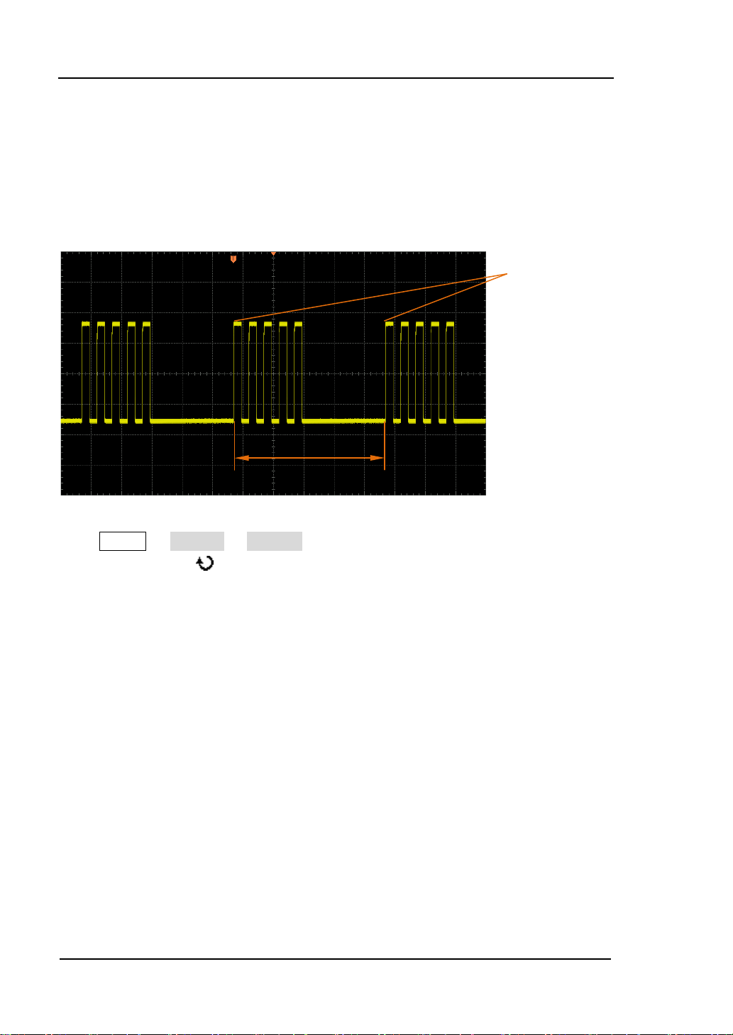
RIGOL 5 To Trigger the Oscilloscope
5-6
Trigger position
Trigger Holdoff
Trigger holdoff could trigger complicated waveforms (e.g. pulse sequence) stably.
Holdoff time is the time the oscilloscope waits to re-enable the trigger circuit. During
the holdoff time, the oscilloscope will not trigger.
Holdoff Time
Press MENU Setting Holdoff in the trigger control area (TRIGGER) at the
front panel and use to change the holdoff time (the default is 100 ns) until the
waveform triggers stably. The adjustable r a nge of the holdoff time is from 100 ns to
10 s.
DS6000 User’s Guide
Page 99

5 To Trigger the Oscilloscope RIGOL
5-7
Trigger Type
DS6000 has abundant trigger functions.
Edge Trigger
Pulse Trigger
Slope Trigger
Video Trigger
Pattern Trigger
RS232 Trigger
I2C Trigger
SPI Trigger
CAN Trigger
FlexRay Trigger
USB Trigger
DS6000 User’s Guide
Page 100

RIGOL 5 To Trigger the Oscilloscope
5-8
Edge Trigger
Trigger on the trigger threshold of the specified edge of the input signal.
Trigger Type:
Press Type to select “Edge”. At this point, the trigger setting inf ormation as shown in
the figure below is displayed at the upper right corner of the screen.
Source Selection:
Press Source to select CH1-CH4, EXT, EXT/5 or AC Line as the Trigger Source. The
current trigger source is displayed at the upper right corner of the screen.
Note: select channel with signal input as trigger source to obtain stable trigger.
Edge Type:
Press Slope to select to trigger on whi ch kind of edge of the input signal. The current
edge type is displayed at the upper right corner of the screen.
: trigger on the rising edge of the input signal when the voltage level meets
the preset Trigger Level.
Trigger Mode:
Press Sweep to select the Trigger Mode (page 5-3) under this trigger type as auto,
normal or single. The corresponding status light of the current trigger mode turns on.
Trigger Setting:
Press Setting to set the trigger parameters (trigger coupling and trigger holdoff)
under this trigger type.
Trigger Level:
Use TRIGGER
trigger mark “
: trigger on the f alling ed ge of the input s ignal when t he voltage lev el meets
the preset Trigger Level.
: trigger on the rising and falling edges of the input signal when the
voltage level meets the preset Trigger Level.
LEVEL to modify the level. An orange trigger level line and the
” appear on the screen and move up and down with the turning of
the knob, while at the same time, the trigger level v alue (e.g.
) at
the lower left corner of the screen also changes accordingly. When stopping turning
the knob, the trigger level line and the trigger mark disappear in about 2 seconds.
DS6000 User’s Guide
 Loading...