

Page 1

RII
R
G
G
O
O
用户手册
RP7000S 系列单端有源探头
L
L
2013 年 11 月
RIGOL Technologies, Inc.
Page 2

Page 3

RIGOL
保证和声明
版权
© 2013 北京普源精电科技有限公司版权所有。
商标信息
RIGOL 是北京普源精电科技有限公司的注册商标。
文档编号
UGE21001-1110
声明
本公司产品受已获准及尚在审批的中华人民共和国专利的保护。
本公司保留改变规格及价格的权利。
本手册提供的信息取代以往出版的所有资料。
对于本手册可能包含的错误,或因手册所提供的信息及演绎的功能,以及
因使用本手册而导致的任何偶然或继发的损失,RIGOL 概不负责。
未经 RIGOL 事先书面许可不得影印复制或改编本手册的任何部分。
产品认证
RIGOL 认证本产品符合中国国家产品标准和行业产品标准及 ISO9001:2008 标
准和 ISO14001:2004 标准,并进一步认证本产品符合其它国际标准组织成员的
相关标准。
联系我们
如您在使用此产品或本手册的过程中有任何问题或需求,可与 RIGOL 联系:
电子邮箱:service@rigol.com
网址:www.rigol.com
RP7000S 用户手册 I
Page 4
RIGOL
II
警告
注意
危险
警告
注意
安全术语和符号
本手册中的术语。以下术语可能出现在本手册中:
警告性声明指出可能会危害操作人员生命安全的条件和行为。
注意性声明指出可能导致本产品损坏或数据丢失的条件和行为。
产品上的术语。以下术语可能出现在产品上:
表示您如果进行此操作可能会立即对您造成危害。
表示您如果进行此操作可能会对您造成潜在的危害。
表示您如果进行此操作可能会对本产品或连接到本产品的其他设备造
成损坏。
产品上的符号。以下符号可能出现在产品上:
高电压 安全警告
保护性
接地端
壳体接地端 测量接地端
RP7000S 用户手册
Page 5
RIGOL
型号 带宽
文档概述
本手册用于指导用户快速了解 RP7000S 系列单端有源探头及其使用方法,并提
供保养与清洁等服务信息。
RP7000S 系列单端有源探头包含如下型号。
PR7150S >1.5GHz
RP7080S >800MHz
本手册主要内容包括:
RP7000S 系列单端有源探头概述
简介探头,包括:一般性检查、探头尺寸、标准附件等。
使用 RP7000S系列单端有源探头
介绍如何使用探头,包括:连接示波器、探头前端的使用、更换探头配件、
调节偏移电压、校准探头等。
保养与清洁
保修概要
性能指标
RP7000S 用户手册 III
Page 6

RIGOL
IV
目录
保证和声明 .............................................................................................. I
安全术语和符号 ..................................................................................... II
文档概述 .............................................................................................. III
RP7000S 系列单端有源探头概述 ..............................................................1
探头简介 .......................................................................................... 2
一般性检查 ...................................................................................... 2
探头尺寸 .......................................................................................... 3
附件和选件 ...................................................................................... 4
有源探头放大器 ................................................................................ 6
探头前端 .......................................................................................... 7
使用 RP7000S系列单端有源探头 .............................................................9
连接示波器 .................................................................................... 10
手持式单端探头前端的使用.............................................................. 12
更换探头配件 ................................................................................. 13
调节偏移电压 ................................................................................. 13
校准探头 ........................................................................................ 14
保养与清洁 ........................................................................................... 15
保修概要 .............................................................................................. 16
性能指标 .............................................................................................. 17
RP7000S 用户手册
Page 7

RP7000S 系列单端有源探头概述
本部分指导用户快速了解 RP7000S 系列单端有源探头。
主要内容包括:
探头简介
一般性检查
探头尺寸
附件
有源探头放大器
探头前端
RIGOL
RP7000S 用户手册 1
Page 8

RIGOL
2
探头简介
RP7000S是针对于高频解决方案的单端有源探头。RP7000S使用快插式探头前
端,支持探头前端更换,提高了探头可用性。允许用户更换探头尖,延长探头的
使用寿命。更换不同的接地片可以适应不同的待测点间距。RP7000S与RIGOL
DS6000/DS4000系列示波器的自动识别接口兼容,可由该接口自动识别和配置。
其卡入式BNC连接器使得与示波器的连接更加方便。RP7000S提供丰富的附件和
选件,并且诸多部件采用可替换的设计原则,可 方便的应用于不同的测试测量解
决方案。
一般性检查
1. 检查运输包装
如运输包装已损坏,请保留被损坏的包装或防震材料,直到货物经过完全
检查且探头通过电性和机械测试。
因运输造成探头损坏,由发货方和承运方联系赔偿事宜。RIGOL公司恕不
进行免费维修或更换。
2. 检查探头
若存在机械损坏或缺失,或者探头未通过电性和机械测试,请联系您的
RIGOL 经销商。
3. 检查附件
请根据本手册附件和选件一节检查随机附件,如有损坏或缺失,请联系您
的RIGOL经销商。
RP7000S 用户手册
Page 9
探头尺寸
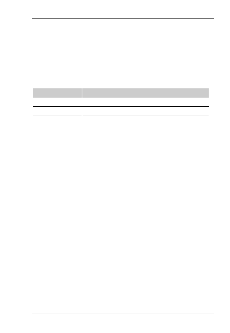
图 1 给出了 RP7000S 系列单端有源探头主体部分的尺寸示意图。
图 1 探头尺寸
RIGOL
RP7000S 用户手册 3
Page 10
RIGOL
4
名称 订货号
数量
附件和选件
本节列出了 RP7000S 系列单端有源探头套件及其标准附件。所列部件均可通过
RIGOL 订购。RP7150S 单端有源探头套件(订货号为 RP7150S)包含
列全部标准附件。如需单独订购附件,请参考
件(订货号为 RP7080S)包含
参考
表 2。
表 1 RP7150S 单端有源探头套件(订货号为 RP7150S)标准附件
PCK100 有源差分探头校准套件
RP7150S 有源探头放大器
手持式单端探头前端
91Ω 探头尖
尖形直接地片
尖形弯接地片
齿形直接地片
齿形弯接地片
标识环(黄、粉、浅蓝、深蓝)
用户手册
探头包
储物盒
表 2 所列全部标准附件。如需单独订购附件,请
表 1。RP7080S 单端有源探头套
PCK100 1
RP7S-0150 1
RP7S-0205 1
RP7-0405 9
RP7-0501 2
RP7-0502 2
RP7-0503 2
RP7-0504 2
RP-0203 8
RP7S-0601 1
RP7-0602 1
RP7-0603 1
表 1 所
RP7000S 用户手册
Page 11

表 2 RP7080S 单端有源探头套件(订货号为 RP7080S)标准附件
名称 订货号
数量
PCK100 有源差分探头校准套件
RP7080S 有源探头放大器
手持式单端探头前端
91Ω 探头尖
尖形直接地片
尖形弯接地片
齿形直接地片
齿形弯接地片
标识环(黄、粉、浅蓝、深蓝)
用户手册
探头包
储物盒
注意:本部分所列附件仅供参考,请以产品实物为准。
PCK100 1
RP7S-0080 1
RP7S-0205 1
RP7-0405 9
RP7-0501 2
RP7-0502 2
RP7-0503 2
RP7-0504 2
RP-0203 8
RP7S-0601 1
RP7-0602 1
RP7-0603 1
RIGOL
RP7000S 用户手册 5
Page 12
RIGOL
6
注意
有源探头放大器
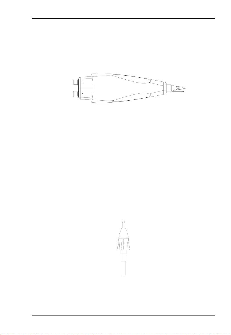
有源探头放大器(图 2)作为有源探头的主体部件,具有大于 1.5GHz 的带宽,
它一端可与 DS6000/DS4000 系列示波器连接,另一端可灵活插入用户所需的探
头前端。
+ -
正负标识
图 2 有源探头放大器
有源探头放大器与探头前端通过插拔方式进行连接。使用单端探头时,在插拔的
过程中,请注意二者的正负极性。极性接反可能造成有源探头性能下降甚至损坏
探头。
手持式单端探头前端在连接处有正负标识。
RP7000S 用户手册
Page 13
RIGOL
探头前端
RP7000S 支持手持式单端探头前端。使用手持式单端探头前端,旋转单端接地
片以改变接地片与探头尖的间距,如
图 3 手持式单端探头前端
其中,探头尖与单端接地片是标准附件,如
可替换部件,如果在使用过程中被损坏,您可以方便地更换新的探头尖或单端接
地片,更换方法请参考
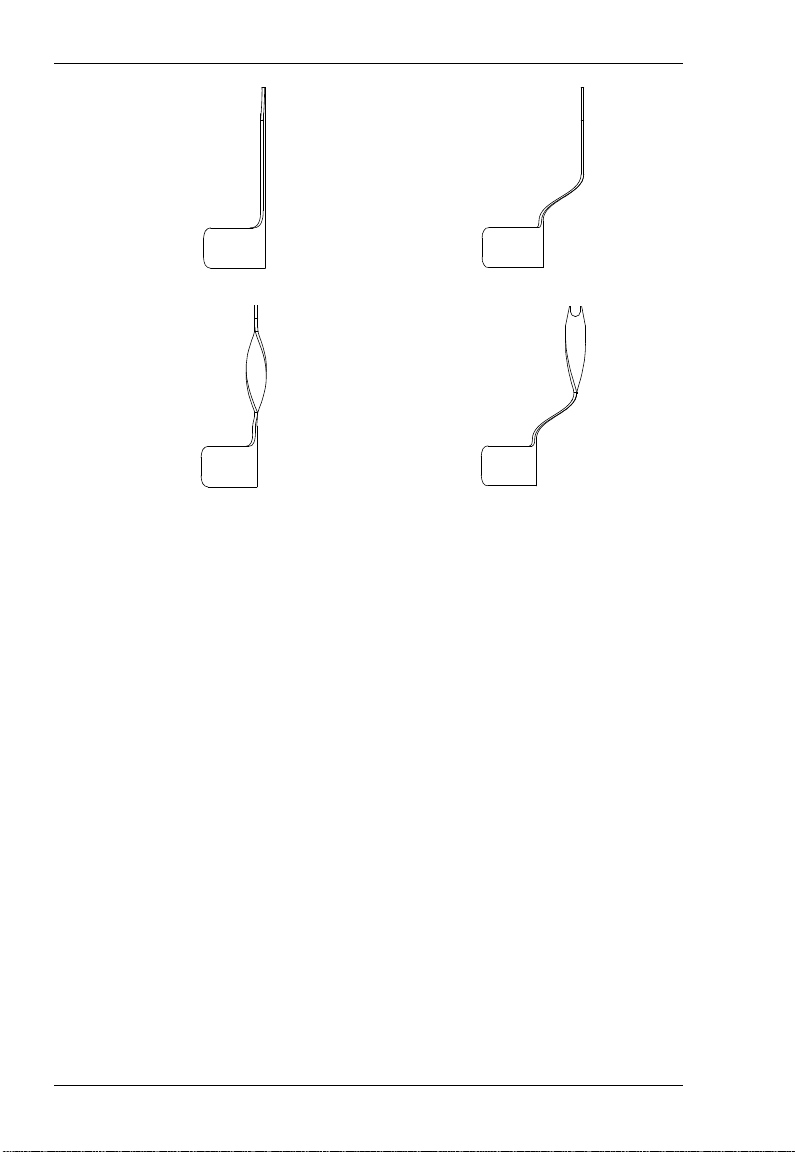
RP7000S 提供四种单端接地片以适应不同的测量要求,各接地片的结构如
所示。
a) 尖形直接地片:适用于近距离测试点的测量。
b) 尖形弯接地片:适用于较远距离测试点的测量。
c) 齿形直接地片:适用于近距离芯片管脚测试点的测量。
d) 齿形弯接地片:适用于较远距离芯片管脚测试点的测量。
更换探头配件。
图 3 所示。
图 4 和图 5 所示。这两种部件均为
图 5
图 4 探头尖
RP7000S 用户手册 7
Page 14
RIGOL
8
(a) 尖形直接地片
齿形直接地片
图 5 接地片
尖形弯接地片
齿形弯接地片
RP7000S 用户手册
Page 15

RIGOL
使用 RP7000S 系列单端有源探头
在使用 RP7000S 系列单端有源探头的过程中,正确的使用方法可以保证探头性
能,延长探头的使用寿命并保证信号测量结果的有效性。本部分将详细介绍
RP7000S 系列单端有源探头的使用方法。
主要内容包括:
连接示波器
手持式单端探头前端的使用
更换探头配件
调节偏移电压
校准探头
RP7000S 用户手册 9
Page 16

RIGOL
10
连接示波器
RP7000S 系列单端有源探头与 RIGOL DS6000/DS4000 系列示波器正确连接
后,示波器自动识别探头并通过前面板为探头提供电源和偏移电压。此时,您可
以通过示波器前面板菜单调节偏移电压(参考
考
校准探头一节)等操作。
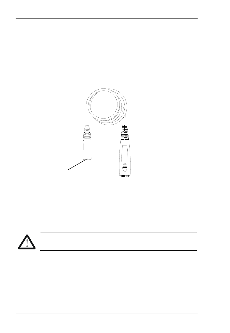
请按照如下步骤连接探头与示波器:
1. 将探头前端与有源探头放大器连接。连接时请注意正负极性。
调节偏移电压一节)和校准探头(参
2. 将有源探头放大器的另一端连接到示波器通道输入或外部触发输入连接器,
并推到紧闭的位置。
RP7000S 用户手册
Page 17

RIGOL
注意
3. 使用任意探头辅助装置将其连接到待测电路中。
4. 需断开探头和示波器的连接时,首先按住探头上的按钮(见左下图),将连
接器从示波器拔出后(见右下图),松开按钮即可。
不要试图从示波器 BNC 连接器上扭动探头,否则,可能导致探头
损坏。
RP7000S 用户手册 11
Page 18

RIGOL
12
注意
手持式单端探头前端的使用
手持式单端探头前端的有效带宽大于 1.5GHz,探头尖与单端接地片的间距可以
通过拨动单端接地片进行调节,探头尖和单端接地片允许更换,从而延长探头的
使用寿命。
使用手持式单端探头前端,您可以方便的测量单端信号。在进行信号测量时,单
端接地片需要接地。探头前端与有源探头放大器连接时,注意二者连接处的正负
标识。
手持式单端探头前端结构如
③
图 6 所示。
①
②
图 6 手持式单端探头前端
① 手持式单端探头前端(RP7S-0205)。
② 91Ω 探头尖(RP7-0405)。
③ 尖形直接地片:转动接地片调节接地片与探头尖的间距(0mm 至 5mm)
(RP7-0501)。
请将接地片就近接地。
RP7000S 用户手册
Page 19

更换探头配件
1. 更换探头前端
更换过程中请小心操作,以免破坏连接部分而影响探头的性能。
更换方法:
① 断开探头前端与有源探头放大器的连接。
② 将新的探头前端垂直插入有源探头放大器。连接单端探头前端时,请
注意正负极性。
2. 更换探头尖
探头尖与探头前端以螺纹的方式进行连接,拆卸和安装探头尖时请注意旋
转的方向和力度。
3. 更换单端接地片
更换单端接地片时,请确保接地片与铜管紧密连接,以保证探头的性能。
RIGOL
调节偏移电压
RIGOL DS6000/DS4000 系列示波器系统为 RP7000S 系列单端有源探头提供偏
移电压。此偏移电压用于将超出有源探头放大器输入动态范围的被测信号调整至
适当的范围,以保证被测信号的完整性。
此偏移电压可通过示波器前面板菜单进行调节。调整方法如下:
1. 按照
2. 打开 DS6000/DS4000 示波器的探头偏移电压控制菜单(前面板操作:CH1
RP7000S 用户手册 13
连接示波器一节所述方法,将 RP7000S 系列单端有源探头连接至
DS6000/DS4000 系列示波器的通道输入端(比如:CH1)。
探头 偏置电压),使用旋钮调节偏移电压值。
Page 20

RIGOL
14
校准探头
在使用 RP7000S 系列单端有源探头前,您可以使用 PCK100 有源探头校准套件
对探头进行校准。使用该套件校准 RP7000S 有源探头的步骤如下:
1. 使用 1 个 BNC-SMA 连接器分别连接校准板和连接线的 BNC(母头),然后将
另一个 BNC-SMA 连接器连接至校准板的另一端(称作部件 1)。
2. 连接 RP7000S 有源探头至示波器的模拟通道(CH1-CH4,本文以 CH1 为例
进行说明)。
3. 打开示波器的探头校准控制菜单(前面板操作:CH1 探头 探头校
准),此时示波器的用户界面会弹出校准提示信息,请按照提示信息将部件
1 连接至示波器,通常情况下,将连接器的 BNC(公头)连接至相应的模拟通
道,将连接线的 BNC(公头)连接至后面板 [Trig Out/Calibration] 端口。
4. 调节探头尖与接地片的间距,将探头尖连接至校准板的中间信号线上,将
接地片连接至信号线的两侧。注意:此处探头尖最好连接至校准板的中心
附近。
5. 按 开始 软键,示波器开始进行校准,探头校准的时间大约 40~50 秒,探
头校准完成时示波器会根据校准结果弹出“探头校准完成”或“探头校准
失败”提示信息。注意:以免影响校准精度,在校准过程中,探针尖及接
地片必须始终与校准板紧密相连。
RP7000S 系列单端有源探头相关的性能指标依赖于探头的校准。完成校准后,
有源探头的直流增益、偏移电压零点和偏移增益均被校准。用户可以通过菜单
CH1 探头 探头信息,查看探头的厂商、型号、序列号和上次校准时间等
信息。
RP7000S 用户手册
Page 21

RIGOL
注意
警告
保养与清洁
保养:
请勿将探头及其附件放置在长时间受到日照的地方。
请勿使任何腐蚀性的液体沾到探头及其附件上。
清洁:
请根据使用情况经常对探头及其附件进行清洁。方法如下:
1. 断开探头与示波器或电压源的连接。
2. 用潮湿但不滴水的软布(可使用柔和的清洁剂或清水)擦试探头及其附件
外部的浮尘。
在重新使用前,请确认探头已经干透,避免因水分造成电气短路甚
至人身伤害。
RP7000S 用户手册 15
Page 22

RIGOL
16
保修概要
RIGOL 承诺其生产仪器的主机和附件,在产品保修期内无任何材料和工艺缺陷。
在保修期内,若产品被证明有缺陷,RIGOL 将为用户免费维修或更换。详细保
修条例请参见 RIGOL 官方网站或产品保修卡的说明。欲获得维修服务或保修说
明全文,请与 RIGOL 维修中心或各地办事处联系。
除本概要或其他适用的保修卡所提供的保证以外,RIGOL 公司不提供其他任何
明示或暗示的保证,包括但不局限于对产品可交易性和特殊用途适用性之任何暗
示保证。在任何情况下,RIGOL 公司对间接的,特殊的或继起的损失不承担任
何责任。
RP7000S 用户手册
Page 23

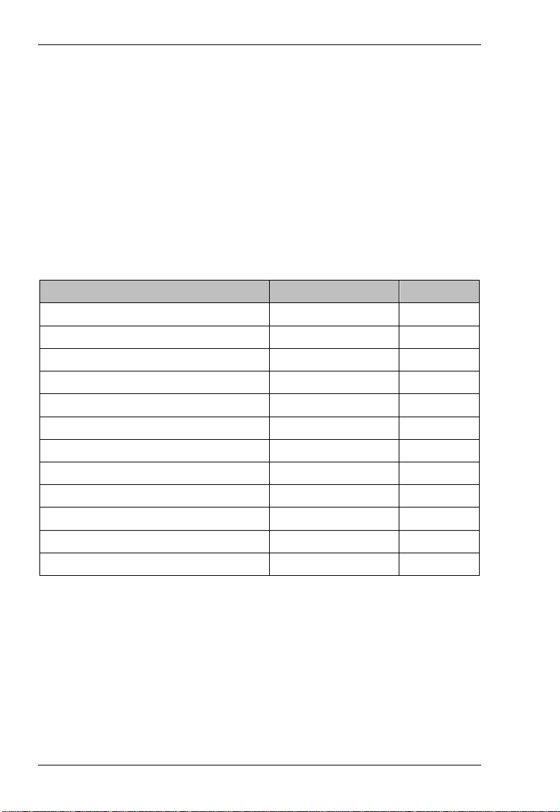
性能指标
指标名称
[1]
[1]
技术指标
带宽
上升时间(计算值)
系统带宽 1GHz (DS6104 或
输入电容
输入电阻
输入动态范围
直流衰减精度
零点偏移误差
<30mV 校准前
偏移电压范围
偏移精度
<3%当前量程 校准前
输入噪声
传输延迟
最大输入电压
静电防护
RP7150S RP7080S
>1.5GHz >800MHz
<265ps <465ps
DS6102)
<5mV 校准后
<1%当前量程 校准后
30V Peak CAT I
800MHz (DS6104 或
<1pF
100kΩ±2%
±6.25V
10:1 ±2%
±12V
70mVpp
7ns
>8kV
DS6102)
[2]
RIGOL
RP7000S 用户手册 17
Page 24

RIGOL
18
环境条件 操作环境
存放环境
一般规格
温度
湿度
海拔
功耗
重量
线长
+5°C ~+40°C -40°C ~+70°C
0 RH~80% RH 0 RH~90% RH
4600m 15300m
1.2W N/A
132±10g
[3]
1305±50g
[4]
1.4m
[1] 典型值,其技术指标会随着示波器的档位不同而改变。
[2] CAT I 和 CAT II 的定义
装置种类(超压种类)I:信号电平,特殊设备或部分设备,无线电通讯和
电子等,相对装置种类(超压种类)II 有更小的瞬态电压。
装置种类(超压种类)II:局部电平,器具,可携带设备等,相对装置种类
(超压种类)III 有更小的瞬态电压。
[3] RP7000S 配备手持式单端前端时的重量。
[4] RP7000S 有源探头套件(含包装)的重量。
RP7000S 用户手册
Page 25

RII
R
G
G
O
O
L
L
User’s Guide
RP7000S Series
Single-Ended Active Probe
RIGOL Technologies, Inc.
Nov. 2013
Page 26

Page 27

RIGOL
I
Guaranty and Declaration
Copyright
© 2013 RIGOL Technologies, Inc. All Rights Reserved.
Trademark Informat ion
RIGOL is a registered trademark of RIGOL Technologies, Inc.
Publicatio n Number
UGE21101-1110
Notices
RIGOL products are protected by patent law in and outside of P.R.C.
RIGOL reserves the right to modify or change parts of or all the
specifications and pricing policies at company’s sole decision.
Information in this publication replaces all previously corresponding
materials.
RIGOL shall not be liable for losses caused by either incidental or
consequential in connection with the furnishing, us e or perf ormance of this
manual as well as any information contained.
Any part of this document is forbidden to be copied or photocopied or
rearranged without prior written approval of RIGOL.
Product Certification
RIGOL guarantees this product conforms to the national and industrial
standards in China as well as the ISO9001:2008 standard and the
ISO14001:2004 standard. Other international standard conformance
certification is in progress.
Contact Us
If you have any problem or requirement when using our products or this
manual, please contact RIGOL Technologies, Inc.
E-mail: service@rigol.com
Website: www.rigol.com
RP7000S User’s Guide
Page 28

RIGOL
High
Safety
Protective
Chassis
Test
Safety Terms and Symbols
Terms in this Ma n ual. The following terms may appe ar in this
manual:
WARNING
Warning statements indica te the conditions or practices that could
result in injuries or loss of life.
CAUTION
Caution statements indicate the conditions or practices that could
result in damage to this product or loss of data.
Terms on the Product. The following terms may appear on the
product:
DANGER indicates a hazard may immediately happen.
WARNING indicates potential hazard may happen.
CAUTION indicates damage to the instrument or other devices connected to
the instrument may happen.
Symbols on the Product. The following symbol s may appear on
the product:
Voltage
II RP7000S User’s Guide
Warning
terminal
Earth
Ground
Ground
Page 29

RIGOL
III
Document Overview
This document is used to guide users to get a quick understanding of the
RP7000S series single-ended active probe as well as its using method. Besides,
this document gives service information relating to general care and cleaning.
RP7000S series single-ended active probe includes the following model.
Model Bandwidth
PR7150S >1.5GHz
PR7080S >800MHz
Main topics in this manual:
RP7000S Series Overview
This chapter gives a brief introduction of the probe, including general
inspection, probe dimensions, standard accessories etc.
To Use RP7000S Series
This chapter introduces how to use the probe, including how to connect to
the oscilloscope, how to use the probe head, how to replace probe
accessories, how to adjust the offset voltage, how to calibrate the probe
etc.
General Care and Cleaning
Warranty
Specifications
RP7000S User’s Guide
Page 30

RIGOL
Contents
Guaranty and Declaration .................................................................... I
Safety Terms and Symbols ................................................................. II
Document Overview .......................................................................... III
RP7000S Series Overview ....................................................................1
Probe Introduction ............................................................................ 2
General Inspection ............................................................................ 2
Probe Dimensions ............................................................................. 3
Accessories and Options .................................................................... 4
Active Probe Amplifier ....................................................................... 6
Probe Head ...................................................................................... 7
To Use RP7000S Series ........................................................................9
To Connect to the Oscilloscope......................................................... 10
To Use Hand-held Single-ended Probe Head ...................................... 12
To Replace Probe Accessories .......................................................... 13
To Adjust Offset Voltage .................................................................. 14
To Calibrate the Probe ..................................................................... 14
General Care and Cleaning ................................................................ 16
Warranty ............................................................................................ 17
Specifications .................................................................................... 18
IV RP7000S User’s Guide
Page 31

RIGOL
1
RP7000S Series Overview
This chapter guides users to quickly get familiar with the RP7000S series
single-ended active probe.
Main topics:
Probe Introduction
General Inspection
Probe Dimensions
Accessories and Options
Active Probe Amplifier
Probe Head
RP7000S User’s Guide
Page 32

RIGOL
Probe Introduction
RP7000S is a single-ended active probe solution for high frequency application.
RP7000S uses plug-in probe head to optimize the performance and usability.
Besides, its replaceable probe tip prolongs the service life of the probe and the
spacing between probe tip and ground collar can be precisely adjusted to fit
different test point spacing. RP7000S is compatible with the auto-identification
port of RIGOL DS6000/DS4000 series oscilloscope and can be recognized and
configured automatically by this port. Its snap-in BNC connector enables easier
connection with the oscilloscope. RP7000S provides various accessories and
options and multiple replaceable components which make it applicable to be
used in different tests and measurements.
General Inspection
1. Inspect the shipping container for damage.
If your shipping container appears to be damaged, keep the shipping
container or cushioning material until you have inspected the contents of
the shipment for completeness and have checked the probe electrically
and mechanically.
If your probe has damaged during shipping, please contact your shipper
and carrier for compensation. RIGOL will provide no free repair or
replacement.
2. Inspect the probe.
If there is any mechanical damage or defect, or if the probe does not pass
electrical and mechanical tests, please contact your RIGOL sales
representative.
2 RP7000S User’s Guide
Page 33

3. Check the Accessories.
Please check the accessories according to Accessories and Options in
this guide. If the accessories are incomplete or damaged, please contact
your RIGOL sales representative.
Probe Dimensions
Figure 1 shows the dimensions of the main parts of RP7000S series
single-ended active probe.
RIGOL
Figure 1 Probe Dimensions
RP7000S User’s Guide 3
Page 34

RIGOL
Accessories and Options
This section lists the probe kits, standard accessories of the RP7000S series
single-ended active probe respectively . All the components listed below can be
ordered from RIGOL. RP7150S Single-ended Active Probe Kit (the ordering
number is RP7150S) contains all the accessories listed in Table 1. If any
accessory or option needs to be ordered separately, please refer to Table 1.
RP7080S Single-ended Active Probe Kit (the ordering number is RP7080S)
contains all the accessories listed inTable 2. If any accessory or option needs
to be ordered separately, please refer to Table 2.
Table 1 Standard Accessories of RP7150S Single-Ended Active Probe Kit
(Ordering No. is RP7150S)
Name Ordering NO. Qty
PCK100 Active Differential Probe
Calibration Kit
RP7150S Single-ended Active Pro be
Amplifier
Hand-held Single-ended Probe Head RP7S-0205 1
91Ω Probe Tip RP7-0405 9
Straight Acuminate Ground Collar RP7-0501 2
Curved Acuminate Ground Collar RP7-0502 2
Straight Dentiform Ground Collar RP7-0503 2
Curved Dentiform Ground Collar RP7-0504 2
Marker Rings
(Yellow/Pink/Light Blue/Dark Blue)
User’s Guide RP7S-0601 1
Probe Bag RP7-0602 1
Storage Box RP7-0603 1
PCK100 1
RP7S-0150 1
RP-0203 8
4 RP7000S User’s Guide
Page 35

RIGOL
Table 2 Standard Accessories of RP7080S Single-Ended Active Probe Kit
(Ordering No. is RP7080S)
Name Ordering NO. Qty
PCK100 Active Differential Probe
Calibration Kit
RP7080S Single-ended Active Pro be
Amplifier
Hand-held Single-ended Probe Head RP7S-0205 1
91Ω Probe Tip RP7-0405 9
Straight Acuminate Ground Collar RP7-0501 2
Curved Acuminate Ground Collar RP7-0502 2
Straight Dentiform Ground Collar RP7-0503 2
Curved Dentiform Ground Collar RP7-0504 2
Marker Rings
(Yellow/Pink/Light Blue/Dark Blue)
User’s Guide RP7S-0601 1
Probe Bag RP7-0602 1
Storage Box RP7-0603 1
Note: the acc essories listed in th is section are only for refer ence, the actual
product is the sta n d ar d.
PCK100 1
RP7S-0080 1
RP-0203 8
RP7000S User’s Guide 5
Page 36

RIGOL
er
Active Probe Amplifier
The active probe amplifier (Figure 2), with more than 1.5GHz bandwidth, is a
main component of the active probe. One end of the active probe amplifier can
be connected to the DS6000 and DS4000 series oscilloscope and the other end
can be connected to the desired probe head.
+ -
Pos/Neg Mark
Figure 2 Active Probe Amplifier
When connecting a probe head to an active probe amplifier, push it
straight in. For single-ended probe, when connecting them, pay attention to
their polarities. If the polarity is reversed, the performance of the active probe
would reduce and the active probe might even be damaged.
CAUTION
There are Pos/Neg markers on the hand-held single-en de d pr o be
head and black mark sleeve on the negative pole of the solder-in
single-ended probe head.
6 RP7000S User’s Guide
Page 37

RIGOL
Probe Head
RP7000S supports hand-held single-ended probe head. Before using it,
rotating the single-ended ground collar adjusts the spacing b et w een t h e
single-ended ground collar and probe tip, as shown in Figure 3.
Figure 3 Hand-held Single-ended Probe Head
Wherein, as shown in Figure 4 and Figure 5, probe tip and single-ended
ground collar are standard accessories and are both replaceable. If any of them
is damaged during use, you can easily replace it with a new one (refer to To
Replace Probe Accessories).
RP7000S provides 4 kinds of single-ended ground collars for different
measurement requirements, the structures of the ground collars are as shown
in Figure 5.
a) Straight Acuminate Ground Collar: applicable to measurement of test point
that is close to the ground point.
b) Curved Acuminate Ground Collar: applicable to measurement of test point
that is relatively far from the ground point .
c) Straight Dentiform Ground Collar: applicable to measurement of chip pin
test point that is close to the ground point.
d) Curved Dentiform Ground Collar: applicable to measurement of chip pin
test point that is relatively far from the ground point.
RP7000S User’s Guide 7
Page 38

RIGOL
Figure 4 Probe Tip
(a)
Straight Acuminate Ground Collar
(c)
Straight Dentiform Ground Collar
Figure 5 Ground Collar
8 RP7000S User’s Guide
Curved Acuminate Ground Collar
Curved Dentiform Ground Collar
(b)
(d)
Page 39

RIGOL
To Use RP7000S Series
During the use of RP7000S series single-ended active probe, correct operations
can ensure the probe performance, prolong the service life of the probe and
ensure the effectiveness of the signal measurement result. This chapter
introduces in detail the using method of the RP7000S series single-ended active
probe.
Main T opics:
To Connect to the Oscilloscope
To Use Hand-held Single-ended Probe Head
To Replace Probe Accessories
To Adjust Offset Voltage
To Calibrate the Probe
RP7000S User’s Guide 9
Page 40

RIGOL
To Connect to the Oscilloscope
After RP7000S is connected correctly to a RIGOL DS6000 or DS4000 series
oscilloscope, the oscilloscope recognizes the probe automatically and provides
both power and offset voltage to the probe. You can adjust the offset voltage
(refer to To Adjust Offset Voltage) and calibrate the probe (refer to To
Calibrate the Probe) by the front panel menu of the oscilloscope.
Please connect the probe to the oscilloscope following the steps below:
1. Connect the probe head (in the figure, taking a hand-held differential
probe head for example) with the active probe amplifier. If single-ended
probe head is used, during the connection, pay attention to their polarities.
2. Connect the other end of the active probe amplifier to the channel input or
external trigger input connector of the oscilloscope and make sure the
connection is tight.
10 RP7000S User’s Guide
Page 41

RIGOL
3. Use any probe auxiliary device to connect the probe to the circuit to be
tested.
4. To disconnect the probe from the oscilloscope, press the button on the
probe (as shown in the left figure below), pull the connector straight out of
the oscilloscope (as shown in the right figure below) and then release the
button.
CAUTION
Do not twist the probe on the BNC connector of the oscilloscope,
or else, the probe might be damaged.
RP7000S User’s Guide 11
Page 42

RIGOL
To Use Hand-held Single-ended Probe Head
Known from Probe Head, RP7000S can easily change the probe head by using
the method introduced in To Replace Probe Accessories. This chapter
introduces how to use the probe heads respectively.
The hand-held single-ended probe head provides an effective bandwidth of
more than 1.5GHz. Besides, the spacing between the single-ended ground
collar and probe tip can be adjusted by rotating the ground collar and the
replaceable probe tip and single-ended ground collar prolong the service life of
the probe.
The hand-held single-ended probe head can be used to measure single-ended
signal. During the measurement, the single-ended ground collar must be
grounded. Pay attention to their polarities when connecting the probe head and
active probe amplifier.
The structure of the hand-held single-ended probe head is as shown in Figure
6.
①
③
②
Figure 6 Hand-held Single-ended Probe Head
12 RP7000S User’s Guide
Page 43

RIGOL
① Hand-held single-ended probe head (RP7S-0205).
② 91Ω probe tip (RP7-0405).
③ Straight acuminate ground collar: rotating the ground collar adjusts the
spacing (0mm to 5mm) between the ground collar and probe tip
(RP7-0501).
CAUTION
Ground the ground collar when using the hand-held single-ended
probe.
To Replace Probe Accessories
1. To replace the probe head
Take care not to damage the connecting part to avoid affecting the probe
performance when replacing the probe head.
Replacing Method:
① Disconnect the current probe head from the active probe amplifier.
② Push the new probe head into the active probe amplifier straightly.
When single-ended probe head is used, pay attention to their
polarities.
2. Replace the probe tip
The probe tip and probe head are connected with screw thread, so please
note the screw rotation and strength when removing and installing the
probe tip.
3. Replace the single-ended ground collar
Make sure the single-ended ground collar is firmly connected to the
copper pipe to ensure the probe performance when replacing it.
RP7000S User’s Guide 13
Page 44

RIGOL
To Adjust Offset Voltage
RIGOL DS6000/DS4000 series oscilloscope can provide offset voltage to the
RP7000S series single-ended active probe. The offset voltage adjusts the
measured signal which exceeds the input dynamic range of the probe within an
appropriate range to ensure the measured signal’s integrity.
You can adjust the offset voltage by operating the front panel menu of the
oscilloscope and the operation method is as shown below.
1. Connect the RP7000S series si n gle-ended active probe to the channel
input terminal (such as CH1) of the DS6000/DS4000 oscilloscope,
referring to To Connect to the Oscilloscope.
2. Open the probe offset voltage control menu of the DS6000/DS4000
oscilloscope (front panel operation: CH1 Probe Bias Voltage) and
rotate the knob to adjust the value.
To Calibrate the Probe
Before using RP7000S series single-ended acti ve probe, you can calibrate it
using the PCK100 active probe calibration kit. The calibration procedures are
shown as below:
1. Connect one BNC-SMA connector to the calibration board and the female
BNC of the cable respectively and then connect the other BNC-SMA
connector to the other part of the calibration board (called part 1).
2. Connect the RP7000S active probe to the analog channel (CH1 to CH4 of
the oscilloscope, illustrations here are based on CH1).
14 RP7000S User’s Guide
Page 45

RIGOL
3. Open the probe calibration control menu (front panel operation: CH1
Probe Probe-Cal). At this point, calibration prompt message is
displayed in the user interface of the oscilloscope. Follow the prompt
message to connect part 1 to the oscilloscope. Generally , connect the BNC
(male) of the connector to the corresponding analog channel and the male
BNC of the cable to the [Trig Out/Calibration] port at the rear panel of
the oscilloscope.
4. Adjust the spacing between the probe tip and the ground collar so as to
connect the probe tip to the middle signal line on the calibration board and
the ground collar to the both sides of the middle signal line. Note: it is
recommended to place the probe tip at the middle of the calibratio n board .
5. Press Start and the oscilloscope starts to calibrate the probe. The
calibration will last for about 40 to 50 seconds. When probe calibration
finished, “Probe calibration finished!” or “Probe calibration failure!” is
displayed in the user interface of the oscilloscope. Note: to ensure the
calibration precision, the probe tips must be firmly connected to the
calibration board duri n g th e calibration.
Note: Relative specifications of the RP7000S series single-ended active probe
depend on the calibration operation. After the calibration is finished, the DC
gain, offset voltage zero and offset gain will be calibrated. User can query the
information about the manufacturer, model, serial number and the last
calibration time of the probe through CH1 Probe Probe Info.
RP7000S User’s Guide 15
Page 46

RIGOL
General Care and Cleaning
General Care:
Do not place the probe and its accessories in places where they will be exposed
to sun light for long peri ods of tim e .
CAUTION
Keep the probe and its accessories away from any corrosive liquid.
Cleaning:
Clean the probe and its accessories regularly according to their operation
conditions using the method below.
1. Disconnect the probe from the oscilloscope or voltage source.
2. Remove the loose dust on the exterior of the probe and its accessories
using a lint-free cloth (with mild detergent or water).
WARNING
Make sure the probe is completely dry before using it to avoid
short circuit and personal injuries.
16 RP7000S User’s Guide
Page 47

RIGOL
Warranty
RIGOL warrants that its products mainframe and accessories wil l be free fro m
defects in materials and workmanship within the warranty period.
If a product is proven to be defective within the respective period, RIGOL
guarantees the free replacement or repair of products which are approved
defective. For detailed warranty description, please refer to RIGOL official
website or the warranty card. To get repair service or a complete copy of the
warranty description, please contact with your nearest RIGOL sales and
service office.
RIGOL does not provide any other warranty items except the one being
provided by this summary and the warranty statement. The warranty items
include but not being subjected to the hint guarantee items related to tradable
characteristic an d an y par ti c u lar purpose. RIGOL will not take any
responsibility in cases regarding to indirect, particular and ensuing damage.
RP7000S User’s Guide 17
Page 48

RIGOL
Specifications
Technical Specifi cat ion s
Item RP7150S RP7080S
Bandwidth >1.5GHz >800MHz
Rise Time <265ps <465ps
System
Bandwidth
Input Capacitance <1pF
Input Resistance 100kΩ±2%
Input Dynamic
Range
DC Attenuation 10:1 ±2%
Zero Offset Error
[1]
Offset Voltage
Range
Offset Accur acy
Input Noise 70mVpp
Propagation Delay 7ns
Max Input Voltage 30V Peak CAT I
Electrostatic
Protection
1GHz (DS6104 or DS6102) 800MHz (DS6104 or DS6102)
±6.25V
<30mV before calibration
<5mV after calibration
±12V
[1]
<3% of current range before calibration
<1% of current range after calibration
[2]
>8kV
18 RP7000S User’s Guide
Page 49

RIGOL
General Characteristics
Environmental
Operating Non-operating
Conditions
Temperature +5°C to +40°C -40°C to +70°C
Humidity 0 RH to 80% RH 0 RH to 90% RH
Altitude 4600m 15300m
Power Consumption 1.2W N/A
Weights 132g±10g
[3]
1305g±50g
[4]
Wire Length 1.4m
[1] Typical value. The specifications would change when different scales are
selected.
[2] CAT I and CAT II Definitions
Installation Category (Overvoltage Category) I: signal level, special
equipment or parts of equipment, telecommunication, electronic, etc.,
with smaller transient voltages than installation category (Overvoltage
Category) II.
Installation Category (Overvoltage Category) II: local level, appliance,
portable equipment etc., with smaller transient voltages than installation
category (Overvoltage Category) III.
[3] The weight of the probe with the hand-held single-ended probe head.
[4] The weight of the RP7000S series single-ended active probe kit with the
probe bag and PCK100.
RP7000S User’s Guide 19
 Loading...