

Page 1

RIGOL
User’s Guide
DS4000E Series Digital Oscilloscope
Jun. 2016
RIGOL TECHNOLOGIES, INC.
Page 2

Page 3

RIGOL
Guaranty and Declaration
Copyright
© 2016 RIGOL TECHNOLOGIES, INC. All Rights Reserved.
Trademark Information
RIGOL is a registered tradem ark of RIGOL TECHNOLOGIES, INC.
Publication Number
UGA21102-1110
Software Version
00.02.03
Software upgrade might change or add product features. Please acquire the latest
version of the manual from RIGOL website or contact RIGOL to upgrade the
software.
Notices
RIGOL produ cts are cov ered by P.R.C. and f oreign pa tents, issue d and pendin g.
RIGOL reserves the right to modify or change parts of or all the specifications
and pricing policies at the company’s s ole de cision .
Information in this publication replaces all previously released materials.
Information in this publication is subject to change without notice.
RIGOL shall not be liable for either incidental or consequential losses in
connection with the furnishing, use, or performance of this manual, as well as
any information contained.
Any part of this document is f orbi dden to be copie d, phot ocopie d, or rearranged
without prior written approval of RIGOL.
Product Certification
RIGOL guarantees that this product conforms to the national and industrial
standards in China as well as the ISO9001:2008 standard and the ISO14001:2004
standard. Other international standard conformance certifications are in progress.
Contact Us
If you have any problem or requirement when using our products or this manual,
please contact RIGOL.
E-mail: [email protected]
Website: www.rigol.com
DS4000E User’s Guide I
Page 4

RIGOL
Safety Requirement
General Safety Summary
Please review the following safety precautions carefully before putting the
instrument into operation so as to avoid any personal injury or damage to th e
instrument and any product connected to it. To prevent potential hazards, please
follow the instructions specified in this manual to use the instrument properly.
Use Proper Power Cord.
Only the exclusive power cord designed for the instrument and authorized for use
within the local country could be used.
Ground the Instrument.
The instrument is grounded through the Protective Earth lead of the power cord. To
avoid electric shock, connect the earth terminal of the power cord to the Pro tec t i ve
Earth terminal before connecting any input or output terminals.
Connect the Probe Correctly.
If a probe is used, the probe ground lead must be connected to earth ground. Do not
connect the ground lead to hi gh volta ge. Imp rope r wa y of conne ction could result in
dangerous voltages being present on the connectors, controls or other surfaces of
the oscilloscope and probes, which will cause potential hazards for operators.
Observe All Terminal Ratings.
To av oid fire or shock hazard, observe all ratings an d markers on the instrume nt and
check your manual for more information about ratings before connecting the
instrument.
Use Proper Overvoltage Protection.
Ensure that no over voltage (su ch as that cause d by a bolt of lightni ng) can reach the
product. Otherwise, the operator might be exposed to the danger of an electric
shock.
Do Not Operate Without Covers.
Do not operate the instrument with covers or panels removed.
Do Not Insert Objects Into the Air Outlet.
Do not insert objects into the air outlet, as doing so may caus e damage to th e
instrument.
Use Proper Fuse.
Please use the specified fuses.
II DS4000E User’s Guide
Page 5

RIGOL
Avoid Circuit or Wire Exposure.
Do not touch exposed junctions and components when the unit is powered on.
Do Not Operate With Suspected Failures.
If you suspect that any damage may occur to the instrument, have it inspected by
RIGOL authorized personnel before further operations. An y maintenance,
adjustment or replacement especially to ci rcuits or accessories must be perf ormed by
RIGOL authorized personnel.
Provide Adequate Ventilation.
Inadequate ventilation may cause an increase of t emperatur e in the instrument,
which would cause damage to the instrument. So please keep the instrument well
ventilated and inspect the air outlet and the fan regularly.
Do Not Operate in Wet Conditions.
To avoid short circuit inside the instrument or electric shock, never operate the
instrument in a humid environment.
Do Not Operate in an Explosive Atmosphere.
To avoid persona l i njuries or damage to the instrument, never o perate the
instrument in an explo sive atmosphere.
Keep Instrument Surfaces Clean and Dry.
T o a void dust or moisture from af fecting the pe rformance of the inst rument, keep th e
surfaces of the instrument clean and dry.
Prevent Electrostatic Impact.
Operate the instrume nt i n an electrost atic discharge protective environ ment to a void
damage induced by static discharges. Always ground both the internal and external
conductors of cables to release static before making connections.
Use the Battery Properly.
Do not expose the battery (if availa ble) to high temperature or fire. Keep it out of the
reach of children. Improper change of a bat tery (lithium battery) may cause an
explosion. Use the RIGOL specified battery only.
Handle with Caution.
Please handle with care during transportation to avoid damage t o keys, knobs,
interfaces, and other parts on the panels.
DS4000E User’s Guide III
Page 6
RIGOL
WARNING
CAUTION
DANGER
It calls attention to an operation, if not correctly pe rformed, could
WARNING
CAUTION
It calls attention to an operation, if not corre ct ly performed, could
Hazardous
Safety
Protective
Chassis
Test
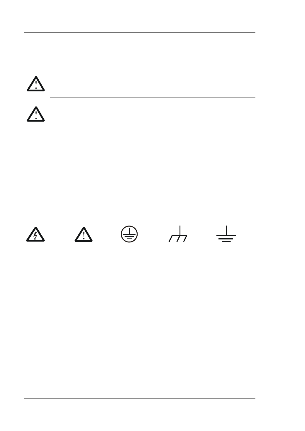
Safety Terms and Symbols
Safety Notices in this Manua l:
Indicates a potentially hazardous situation or practice which, if not
avoided, will result in serious injury or death.
Indicates a potentially hazardous situation or practice which, if not
avoided, could result in damage to the product or los s of i mportant data.
Safety Terms on the Product:
result in injury or hazard immediately.
It calls attention to an operation, if not correctly pe rformed, could
result in
result in damage to the product or other devices connected to the
product.
Safety Symbols on the Product:
potential injury or hazard.
Voltage
Warning
Earth
Terminal
Ground
IV DS4000E User’s Guide
Ground
Page 7

RIGOL
Allgemeine Sicherheits Informationen
Überprüfen Sie diefolgenden Sicherheitshinweise
sorgfältigumPersonenschädenoderSchäden am Gerätundan damit verbundenen
weiteren Gerätenzu vermeiden. Zur Vermeidung vonGefahren, nutzen S ie bitte das
Gerät nur so, wiein diesem Handbuchangegeben.
Um Feuer oder Verletzungen zu vermeiden, verwenden Sie ein
ordnungsgemäßes Netzkabel.
Verwenden Sie für dieses Gerät nur das für ihr Land zugelass ene u nd genehm igte
Netzkabel.
Erden des Gerätes.
Das Gerät ist durch den Schutzleiter im Netzkabel geerdet. Um Gefahren durch
elektrischen Schlag zu vermeiden , ist es unerlässlich, die Er dung durchzufüh ren. Erst
dann dürfen weitere Ein- oder Aus gä nge verbun den werden.
Anschluss einesTastkopfes.
Die Erdungsklemmen der Sonden sindauf dem gleichen Spannungs pegel des
Instruments geerdet. SchließenSie die Erdungsklemmen an keine hohe Spannung
an.
Beachten Sie alle Anschlüsse.
Zur Vermeidung von Feuer oder Stromschlag, beachten Sie alle Bemerkungen und
Markierungen auf dem Instrument. Befolgen Sie die Bedienungsanleitung für w eitere
Informationen, bevor Sie weitere Anschlüsse an das Instrument legen.
Verwenden Sie einen geeigneten Überspannungsschutz.
Stellen Sie sicher, daß keinerlei Überspannung (wie z.B. durch Gewitter verursacht)
das Gerät erreichen kann. Andernfallsbestehtfür den Anwender die
GefahreinesStromschlages.
Nicht ohne Abdeckung einschalten.
Betreiben Sie das Gerät nicht mit entfernten Gehäuse-Abdeckungen.
Betreiben Sie das Gerät nicht geöffnet.
Der Betrieb mit offenen oder entfernten Gehäuseteilen ist nicht zulässig. Nichts in
entsprechende Öffnungen stecken (Lüfter z.B.)
Passende Sicherung verwenden.
Setzen Sie nur die spezifikationsgemäßen Sicherungen ein.
Vermeiden Sie ungeschützte Verbindungen.
Berühren Sie keine unisolierten Verbindungen oder Baugrup pen, während das Gerät
in Betrieb ist.
DS4000E User’s Guide V
Page 8

RIGOL
Betreiben Sie das Gerä t n ic h t i m Fehlerfall.
Wenn Sie am Gerät einen Defekt vermuten, sorgen Sie dafür, bevor Sie das Gerät
wieder betreiben, dass eine Untersuchung durch RIGOL autorisiertem Personal
durchgeführt wird. Jedwede Wartung, Einstellarbeit en oder Austausch v on Teilen am
Gerät, sowie am Zubehör dürfen nur von RIGOL autorisiertem Personal
durchgeführt werd en.
Belüftung sicherstellen.
Unzureichende Belüftung kann zu Temperaturanstiegen und somit zu thermischen
Schäden am Gerät führen. Stellen Sie deswegen die Belüftung sicher und
kontrollieren regelmäßig Lüfter und Belüftungsöffnungen.
Nicht in feuc h te r Um g ebung betreiben.
Zur Vermeidun g von Kurzschluß im Geräteinneren und Stromschlag betreiben Sie das
Gerät bitte niemals in feuchter Umgebung.
Nicht in explosiver Atmosphäre betreiben.
Zur Ve rm e idung von Personen- und Sachs chä den ist es unumgä ngli ch, das Ger ät
ausschließlich fernab jedweder explosiven Atmosphäre zu betreiben.
Geräteoberflächen sauber und trocken halten.
Um den Einfluß von Staub und Feuchtigkeit aus der Luft auszuschließen, halten Sie
bitte die Geräteoberflächen sauber und trocken.
Schutz gegen elektrostatische Entladung (ESD).
Sorgen Sie für eine elektrostatisch geschützte Umgebung, um somit Schäden und
Funktionsstörungen durch ESD zu vermeiden. Erden Sie vor dem Anschluß immer
Innen- und Außenleiter der V erbindungsleitung, um st atische Aufladung zu entladen.
Die richtige Verwendung desAkku.
Wenneine Batterieverwendet wird, vermeiden Sie hohe Temperaturen bzw. Feuer
ausgesetzt werden. Bewahren Sie es außerhalbder Reichweitevon Kindern auf.
Unsachgemäße Änderung derBatterie (Anmerkung: Lithium-Batterie) kann zu einer
Explosion führen. V e rw e ndenSie nur von RIGOL angegebenenAkkus.
Sicherer Transport.
Transportieren Sie das Gerät sorgfältig (Verpackung!), um Schäden an
Bedienelementen, Anschlüssen und anderen Teilen zu vermeiden.
VI DS4000E User’s Guide
Page 9
RIGOL
CAUTION
DANGER
weist auf eine Verletzung ode r Gefäh r dun g hin, die sof ort
WARNING
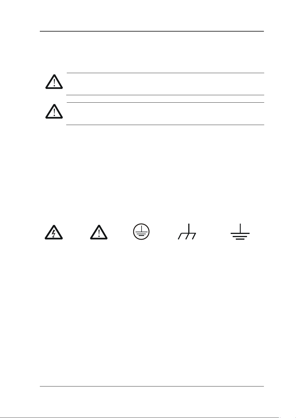
Sicherheits Begriffe und S ymb ole
Begriffe in diesem Guide:
WARNING
Die Kennzeichnung WARNING beschreibt Gefahren q ue llen die leibliche
Schäden oder den Tod von Personen zur Folge haben können.
Die Kennzeichnung Caution (Vorsicht) beschreibt Gefahrenquellen die
Schäden am Gerät hervorrufen können.
Begriffe auf dem Produkt:
geschehen kann.
weist auf eine Ve rletzung oder Gefährdung hin, die möglicherweise
nicht sofort geschehen.
CAUTION weist auf eine Verletzun g ode r Gefährdung hin und bedeutet, dass
eine mögliche Beschädigung des Instruments oder anderer
Gegenstände auftreten kann.
Symbole auf dem Produkt:
Gefährliche
Spannung
SicherheitsHinweis
Schutz-erde Gehäusemasse Erde
DS4000E User’s Guide VII
Page 10
RIGOL
WARNING
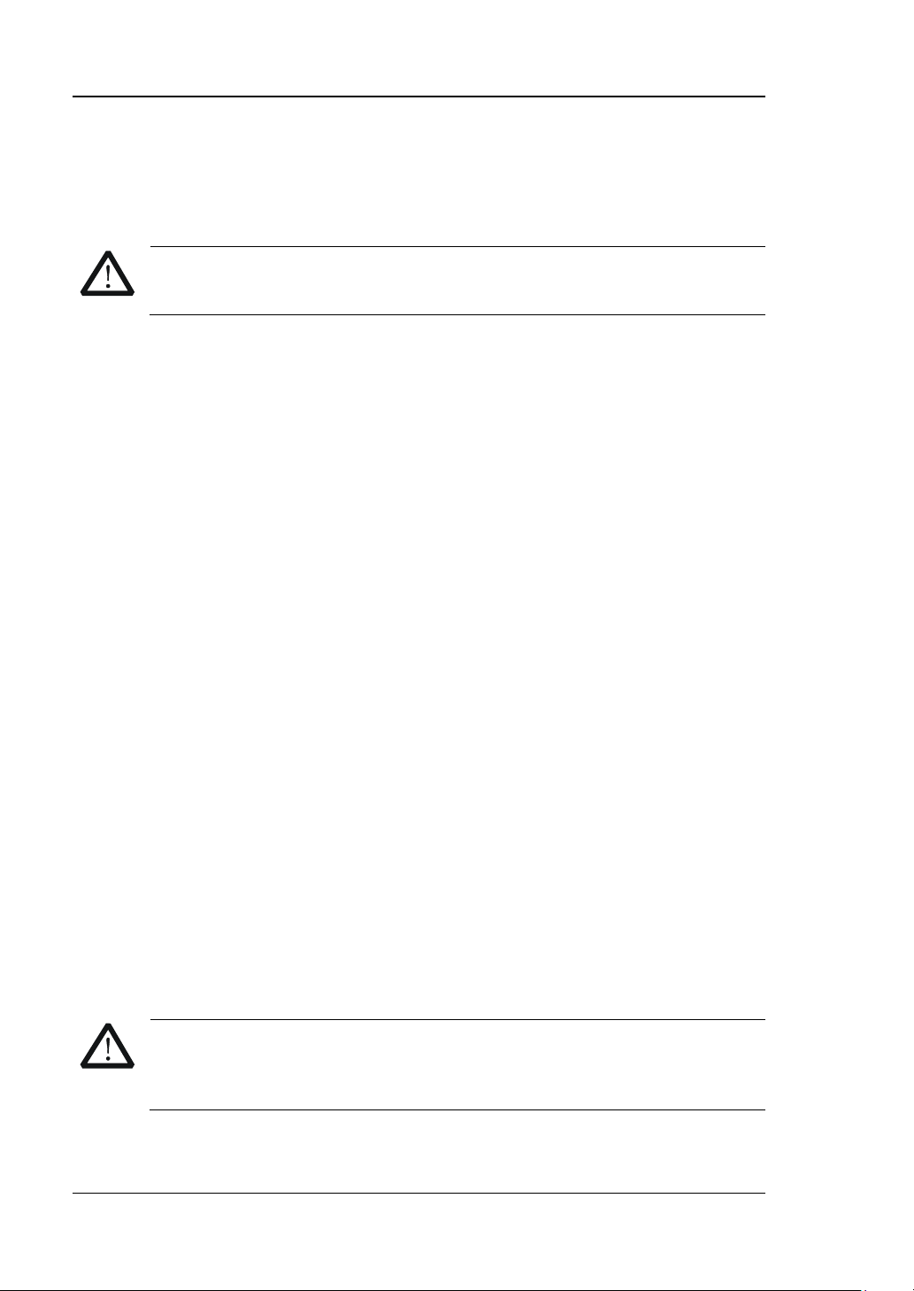
Measurement Category
DS4000E series digital oscilloscopes can make measurements in measurement
category I.
WARNING
This oscilloscope can only be used for measurements within its specified
measurement categories.
Measurement Category Definitions
Measuremen t c ategory I is for measurements performed on circuits not directly
connected to MAINS. Example s are measureme n t s on circuits n ot derived fro m
MAINS, and specially protected (internal) MAINS derived circuits. In the latter case,
transient stresses are variable. For that reason, the transient limit capability of the
equipment is made known to the user.
Measurement category II is for measurements performed on circuits directly
connected to a low voltage installation. Examples are measurements on household
appliances, portable tools and similar equipment.
Measurement category III is for measurements performed in building installations.
Examples are measurements on distribution boards, circuit-breakers, wiring,
including cables, bus-bars, junction boxes, switches, socket-outlets in the f ixed
installation, equipment for industrial use and some other equipment, for example,
stationary motors with permanent connection to the fixed installation).
Measurement category IV is for measurements performed at the source of a
low-voltage installation. Examples are electricity meters and measurements on
primary overcurrent protection devices and ripple control units.
Ventilation Requirement
This oscilloscope uses fan to force cooling. Please make sure that the air intake and
exhaust areas are free from obstructions and have free air. When using the
oscilloscope in a bench-top or rack setting, provide at least 10 cm clearance beside,
above and behind the instrument for adequate ventilation.
VIII DS4000E User’s Guide
Inadequate ventilation may cause a temperature increase which can
damage the instrument. So please keep the instrument well ventilated
during operation and inspect the intake and fan regularly.
Page 11
RIGOL
WARNING
WARNING
Working Environment
Temperature
Operating: 0℃ to +50℃
Non-operating: -40℃ to +70℃
Humidity
0℃ to +30℃: ≤95% relative humidity
+30℃ to +40℃: ≤75% relative humidity
+40℃ to +50℃: ≤45% relative humidity
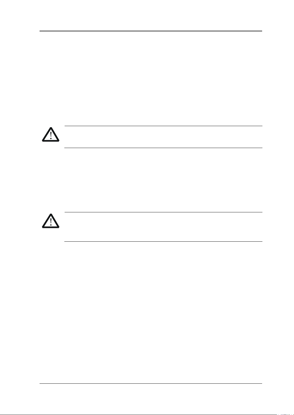
To avoid short circuits or electric shock, please do not operate in humid
environment.
Altitude
Operating: below 3 km
Non-operating: below 15 km
Installation (Overvoltage) Category
This product is powered by mains conforming to installation (overvoltage) category
II.
Make sure that no ove rvoltage (such as that cause d by a thunderbolt) can
reach the product, or else the operator might be exposed to the danger of
electric shock.
Installation (Overvoltage) Cate g ory Defini tions
Installation (overvoltage) category I refers to signal level which is applicable to
equipment measurement terminals connected to the source circuit. In these
terminals, precautions are done to limit the transient voltage to the corresponding
low level.
Installation (overvoltage) category II refers to the local power distribution level
which is applicable to equipment connected to the AC line (AC powe r) .
Pollution Degree
Degree 2
Pollution Degree Definitions
Pollution degree 1: No pollution or only dry, non-conductive pollution occu rs. The
pollution has no influence. For example, a clean room or air-conditioned office
environment.
Pollution degree 2: Normally only dry, non-conductive pollution occurs. An occasional
and temporary conductive environme nt may caused by condensation. Fo r example, a
DS4000E User’s Guide IX
Page 12
RIGOL
CAUTION
WARNING
general indoor environment.
Pollution degree 3: Conductiv e pollution occurs, or dry, non-conductive pollution
occurs which becomes conductive due to condensation. For example, a sheltered
outdoor environment.
Pollution degree 4: Pollution that generates persistent conductivity through
conductive dust, rain, or snow. For exa mple, outdoor locations.
Safety Class
Class 1 – Grounded Product
General Care and Cleaning
Care
Do not store or leave the instrument where it may be exposed to direct sunlight for
long periods of time.
Cleaning
Clean the instrument regularly according to its operating conditions.
1. Disconnect the instrument from all power sources.
2. Clean the external surfaces of the i ns trume nt with a soft cloth dampened with
mild detergent or water. When cleaning the LCD, take care to avoid scarifying it.
To avoid damage to the instrument, do not expose it to caustic liquids.
To avoid short-circuit resulting from moisture or personal injuries, ensure
that the instrument is completely dry before connecting it to the power
supply.
X DS4000E User’s Guide
Page 13
RIGOL
Environmental Considerations
The following symbol indicates that this product complies with the WEEE Directive
2002/96/EC.
Product End-of-Life Handling
The equipment may contain substances that could b e ha rmful to the envi ronm ent o r
human health. To avoid the release of such substances into the environment and
avoid harm to human health, we recommend you to recycle this product
appropriately to ensure that most materials are reused or recycled properly. Please
contact your local authorities for disposal or recycling info rmatio n.
DS4000E User’s Guide XI
Page 14

RIGOL
DS4000E Series Overview
The DS4000E series is a high-performance digital oscilloscope designed to meet the
demands of the mainstream market for the design , debugging, and testing purposes.
Its 4-channel design and high cost-efficiency will invigorate new vitality to the
market of the economical oscilloscopes, offering more choices for the low-cost
testing and measurement solutions.
Main feature s:
Bandwidth: 100 MHz, 200 MHz
Real-time sample rate: up to 2 GSa/s for each channel
Memory depth (standard): up to 14 Mpts for each channel
4 analog channels (standard)
Waveform capture rate: up t o 60,000 waveform s per second
Waveform record, playback, and analysis functions (standard, up to 127,000
frames)
Innovative "UltraVision" technology
A variety of trigger and bus decoding functions
Low noise floor, with the minimum vertical scale 1mV/div
A variety of interfaces: USB HOST&DEVICE, LAN (LXI-C), VGA, AUX, USB-GPIB
(optional)
Novel and sophisticated industrial design, easy for operation
9-inch WVGA, 256-level intensity grading display
XII DS4000E User’s Guide
Page 15

RIGOL
Document Overview
Main Topics in this manual:
Chapter 1 Quick Start
Introduce the preparations before using the instrument and introduce the
instrument.
Chapter 2 Vertical System Setting
Introduce the functions of the vertical system of the oscilloscope.
Chapter 3 Horizontal System Setting
Introduce the functions of the horizontal system of the oscilloscope.
Chapter 4 Sample System Setting
Introduce the functions of the sample system of the oscilloscope.
Chapter 5 Trigger
Introduce the trigger mode, trigger coupling, trigger holdoff, external trigger and
various trigger types of the oscilloscope.
Chapter 6 Operations and Measurements
Introduce how to ma ke mat h operation, auto measurement and cursor
measurement.
Chapter 7 Protocol Decoding
Introduce how to decode the input signal using those common protocols.
Chapter 8 Reference Waveform
Introduce how to compare the input waveform with the reference waveform.
Chapter 9 Pass/Fail Test
Introduce how to monitor the input signal using the Pass/Fail test.
Chapter 10 Waveform Recording
Introduce how to record waveform as well as how to play back and analyze the
recorded waveform.
Chapter 11 Display Control
Introduce how to control the display of the oscilloscope.
Chapter 12 Store and Recall
Introduce how to perform external/internal storage and recall.
DS4000E User’s Guide XIII
Page 16
RIGOL
Chapter 13 System Function Sett in g
Introduce how to set the remote interface a nd system-related functions.
Chapter 14 Remote Control
Introduce how to control the oscilloscope remotely.
Chapter 15 Troubleshooting
Introduce how to deal with common failures of the oscilloscope.
Chapter 16 Specifications
List the specifications and general specifications of the oscilloscope.
Chapter 17 Appendix
Provide common information such as options and accessories.
Format Conventions in this Manual:
1. Key
The key at the front panel is denot e d b y the format of “Button Name (Bol d ) +
Text Box”. For example, Utility denotes the “Utility” key.
2. Menu Softkey
The menu softkey is denoted by the format of “Menu Word (Bold) + Character
Shading”. For example, System denotes the “System” menu softkey under
Utility.
3. Operation Step
The next step of operatio n i s denoted by a n a rrow “”. For example, Utility
System denotes pressing Utility at the front panel and then pressing System.
4. Knob
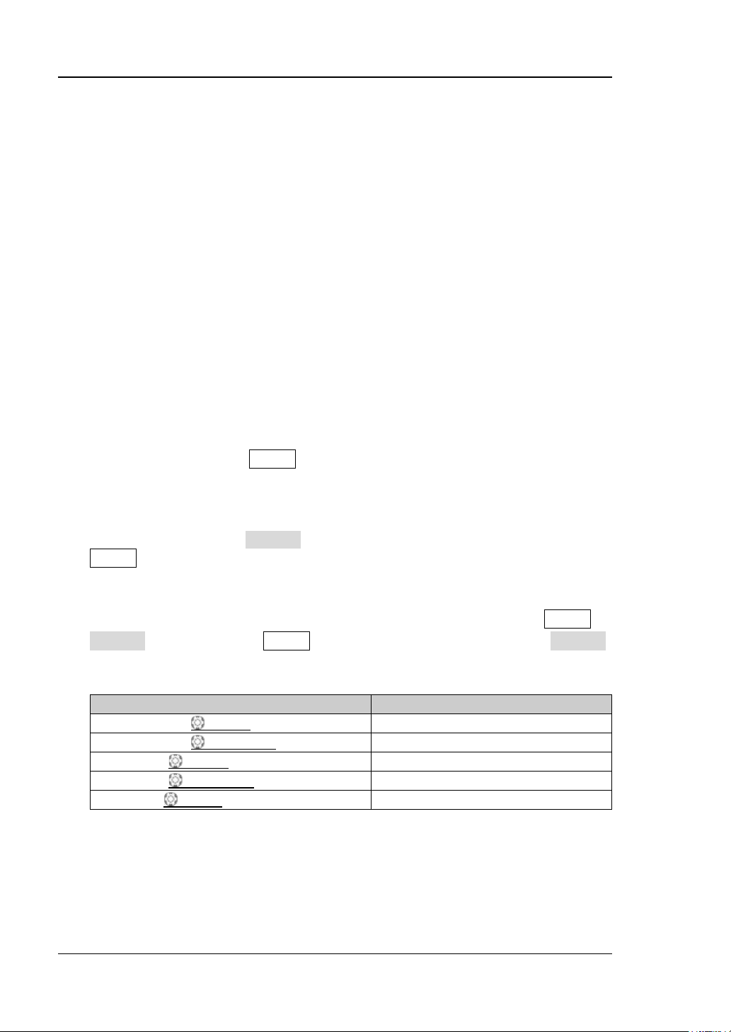
Label Knob
HORIZONTAL SCALE
HORIZONTAL POSITION
VERTICAL SCALE
VERTICAL POSITION
TRIGGER LEVEL
Horizontal Time Base Knob
Horizontal Position Knob
Channel Verti ca l Scale Knob
Channel Verti ca l Position Knob
Trigger Level Knob
XIV DS4000E User’s Guide
Page 17
RIGOL
DS4024E
200 MHz
4
DS4014E
100 MHz
4
Content Conventions in this Manual:
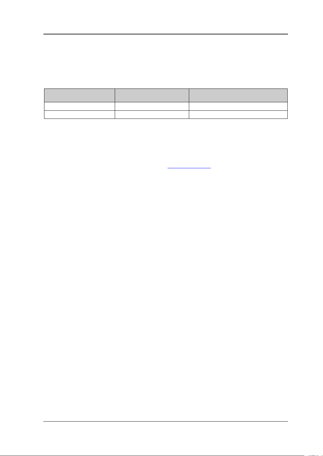
DS4000E series includes the following models. Unless otherwise noted, this manual
takes DS4024E as an example to illustrate the functions and performances of
DS4000E series.
Model Bandwidth Number of Channels
User Manuals of this Product:
The main manuals of this product include the Quick Guide, User’s Guide,
Programming Guide and etc. For the newest version of the desired manual, please
download it from RIGOL official website (
www.rigol.com).
DS4000E User’s Guide XV
Page 18

RIGOL Contents
Contents
Guaranty and Declaration ......................................................................... I
Safety Requirement ................................................................................. II
General Safety Summary........................................................................... II
Safety Terms and Symbols ....................................................................... IV
Allgemeine Sicherheits Informationen ........................................................ V
Sicherheits Begriffe und Symbole ............................................................. VII
Measurement Category .......................................................................... VIII
Ventilation Requirement ......................................................................... VIII
Working Enviro nment .............................................................................. IX
General Care and Cleaning ........................................................................ X
Environmental Considerations ................................................................... XI
DS4000E Series Overview .................................................................... XII
Document Overview ............................................................................ XIII
Chapter 1 Quick Start ........................................................................ 1-1
General Inspection ................................................................................. 1-2
Appearance and Dime nsions ................................................................... 1-3
To Prepare the Oscilloscope for Use ......................................................... 1-4
To Remove the Protective Cover ........................................................ 1-4
To Adjust the Supporting Legs .......................................................... 1-4
To Connect to Powe r Supply ............................................................. 1-5
Power-on Inspection ........................................................................ 1-5
To Connect the Probe ....................................................................... 1-6
Passive Probe Function Ins pection& C om pensat ion Adjustment ............. 1-9
Front Panel Overview ........................................................................... 1-11
Rear Panel Overview ............................................................................ 1-12
Front Panel Function Overview .............................................................. 1-14
VERTICAL ..................................................................................... 1-14
HORIZONTAL ................................................................................ 1-15
TRIGGER ...................................................................................... 1-16
CLEAR .......................................................................................... 1-17
AUTO ........................................................................................... 1-17
RUN/STOP .................................................................................... 1-17
XVI DS4000E User’s Guide
Page 19

Contents RIGOL
SINGLE ......................................................................................... 1-17
Multi-function Knob ........................................................................ 1-18
Navigation Knob ............................................................................ 1-18
Default ......................................................................................... 1-19
Print ............................................................................................. 1-19
Function Keys ................................................................................ 1-19
Record .......................................................................................... 1-20
User Interface ...................................................................................... 1-21
To Use the Security Lock ....................................................................... 1-27
To Use the Built-in Help System ............................................................. 1-28
Chapter 2 Vertical Sy stem Setting ...................................................... 2-1
To Turn the Channel On/Off .................................................................... 2-2
To Adjust the Vertical Scale .................................................................... 2-3
To Adjust the Vertical Position ................................................................. 2-4
To Specify the Channel Coupling ............................................................. 2-5
To Specify the Bandwidth Limit ............................................................... 2-6
To Set the Probe ................................................................................... 2-6
Passive Probe ................................................................................. 2-7
Active Probe ................................................................................... 2-8
Tek Probe ....................................................................................... 2-9
To Specify the In pu t Impedance ............................................................ 2-11
To Turn Waveform Invert On/Off ............................................................ 2-12
To Specify the Vertical Reference ........................................................... 2-12
To Specify the Amplitude Unit ................................................................ 2-13
To Set the Channel Label....................................................................... 2-13
To Set the Delay Calibration................................................................... 2-15
Chapter 3 Horizontal System Setting .................................................. 3-1
To Adjust the Horizontal Time Base ......................................................... 3-2
To Adjust the Horizontal Position ............................................................. 3-3
To Specify the Time Base Mode .............................................................. 3-4
Y-T Mode ....................................................................................... 3-4
X-Y Mode ....................................................................................... 3-4
Roll Mode ....................................................................................... 3-7
To Turn Delayed Sweep On /Off ............................................................... 3-8
To Specify the Horizontal Reference ....................................................... 3-10
Chapter 4 Sample System Setting ...................................................... 4-1
DS4000E User’s Guide XVII
Page 20

RIGOL Contents
Sample Mode ......................................................................................... 4-2
Sample Rate .......................................................................................... 4-2
To Specify the Acquisition Mo de ............................................................... 4-3
Normal ........................................................................................... 4-4
Average .......................................................................................... 4-4
Peak Detect .................................................................................... 4-5
High Resolution ............................................................................... 4-5
To Set the Memory Depth ....................................................................... 4-6
To Turn Anti-aliasing On/Off .................................................................... 4-7
Chapter 5 Trigger ............................................................................... 5-1
Trigger Source ....................................................................................... 5-2
Trigger Level .......................................................................................... 5-3
Trigger Mode ......................................................................................... 5-4
Trigger Coupling..................................................................................... 5-6
Trigger Holdoff ....................................................................................... 5-7
Noise Rejection ...................................................................................... 5-8
Trigger Output Connector........................................................................ 5-8
Edge Trigger .......................................................................................... 5-9
Pulse Trigger ....................................................................................... 5-10
Runt Trigger ........................................................................................ 5-13
Nth Edge Trigger .................................................................................. 5-17
Slope Trigger ....................................................................................... 5-19
Video Trigger ....................................................................................... 5-23
Pattern Trigger ..................................................................................... 5-26
RS232 Trigger ...................................................................................... 5-28
I2C Trigger .......................................................................................... 5-31
SPI Trigger .......................................................................................... 5-35
CAN Trigger ......................................................................................... 5-38
FlexRay Trigger .................................................................................... 5-43
LIN TRIGger (Option) ........................................................................... 5-45
USB Trigger ......................................................................................... 5-48
Chapter 6 Operations and Measurements .......................................... 6-1
To Make Math Operati on ......................................................................... 6-2
Basic Operations .............................................................................. 6-3
FFT ................................................................................................ 6-5
Digital Filter .................................................................................... 6-9
XVIII DS4000E User’s Guide
Page 21

Contents RIGOL
Logic Operation ............................................................................. 6-11
Advanced Operation ....................................................................... 6-14
MAT H Wav e form V ertical Cont rol ..................................................... 6-19
To Make Auto Measurement .................................................................. 6-20
Quick Measurement after AUTO....................................................... 6-21
To Make One-key Measurement ....................................................... 6-22
To Set the Threshold ...................................................................... 6-29
To Specify the Measurement Range ................................................. 6-30
To Clear the Measurement Results ................................................... 6-31
To Turn the Statistic Function On/Off ............................................... 6-32
To Turn the Measurement History On/Off ......................................... 6-33
To Make All Measurement ............................................................... 6-34
To Turn the Frequency Counter O n/Off ............................................. 6-35
To Set the Measurement Results Display .......................................... 6-35
To Make Cursor Measurement ................................................................ 6-36
Manual Mode ................................................................................. 6-37
Track Mode ................................................................................... 6-43
Auto Mode .................................................................................... 6-47
X-Y Mode ...................................................................................... 6-49
Chapter 7 Protocol Decoding .............................................................. 7-1
Parallel Decoding ................................................................................... 7-2
RS232 Decodi n g (Option) ....................................................................... 7-6
I2C Decoding (Option) .......................................................................... 7-13
SPI Decoding (Option) .......................................................................... 7-17
CAN Decoding (Option) ......................................................................... 7-22
FlexRay Decoding (Option) .................................................................... 7-27
LIN Decoding (Option) .......................................................................... 7-32
Chapter 8 Reference Waveform .......................................................... 8-1
To Turn the Reference Waveform Channel On/Off ..................................... 8-2
To Select the Current Reference Wavef orm Channel .................................. 8-3
To Set the Reference Waveform Color...................................................... 8-3
To Select the Reference Waveform Source Channel ................................... 8-4
To Save and Display the Reference Waveform .......................................... 8-4
To Adjust the Reference Waveform Display .............................................. 8-5
To Export the Reference Waveform File ................................................... 8-5
To Impo rt from the Reference Waveform File ........................................... 8-6
DS4000E User’s Guide XIX
Page 22

RIGOL Contents
Chapter 9 Pass/ Fail Test .................................................................... 9-1
To Enable or Disable the Pass/Fail Test Function ........................................ 9-2
To Start or Stop the Pass/Fail Test Operation ............................................. 9-2
To Specify the So urce ............................................................................. 9-3
To Set the Test Mask .............................................................................. 9-3
Screen Region Mode ........................................................................ 9-4
Cursor Region Mode ......................................................................... 9-5
To Turn the Test Result Display On/Off ..................................................... 9-7
To Set the Output Form of Test Failure ..................................................... 9-7
To Sav e t he Test Mask Range .................................................................. 9-9
To Load the Test Mask Range .................................................................. 9-9
Chapter 10 Waveform Recording ................................................. 10-1
To Record Waveform Using the “Record” Mode ....................................... 10-2
To Record Waveform Using the “Open” Mode .......................................... 10-5
To Play Back the Waveform Rec o r ded ..................................................... 10-6
Manual Playback ............................................................................ 10-6
Auto Playback ............................................................................... 10-7
To Analyze the Recorded Waveform ..................................................... 10-10
To Set the Template ( Trace Mode) ................................................. 10-15
To Create the Pass/Fail Test Mask (Pass/Fail Test Mode) .................. 10-16
Chapter 11 Display Control .......................................................... 11-1
To Specify the Display Type ................................................................... 11-2
To Set the Persistence Time .................................................................. 11-2
To Set the Waveform Brightness ............................................................ 11-4
To Specify the Screen Grid Type............................................................. 11-4
To Set the Grid Brightness..................................................................... 11-4
To Set the Menu Display Time ............................................................... 11-5
Chapter 12 Stor e and Reca ll ........................................................ 12-1
Storage System .................................................................................... 12-2
Storage Type ....................................................................................... 12-3
To P e rform Intern al Storage and Recall .................................................. 12-6
To P e rform External Storage and Recall .................................................. 12-7
Disk Management ................................................................................ 12-9
To Select File Type ....................................................................... 12-10
To Create a New File or Folder ...................................................... 12-10
To Delete a File or Folder .............................................................. 12-14
XX DS4000E User’s Guide
Page 23

Contents RIGOL
To Rename a File or Folder ........................................................... 12-15
To Clear the Local Memory ............................................................ 12-15
Factory .............................................................................................. 12-16
Chapter 13 System Func tion Setting ............................................ 13-1
Remote Int e rface Configuration ............................................................. 13-2
To Configure the LAN Interface ....................................................... 13-2
To Configure the USB In t erface ....................................................... 13-7
To Set the GPIB Address ................................................................. 13-7
System-related ..................................................................................... 13-8
Sound ........................................................................................... 13-8
Language ...................................................................................... 13-8
System Informat i on ........................................................................ 13-8
Power-on Load .............................................................................. 13-8
System Time ................................................................................. 13-9
Self-test Information .................................................................... 13-10
Screen Saver ............................................................................... 13-10
Error Informa t ion ......................................................................... 13-10
Self-calibration ............................................................................. 13-11
Print Setting ................................................................................ 13-12
Power Status ............................................................................... 13-14
External Trigger Impedance .......................................................... 13-14
Aux Output ................................................................................. 13-15
Reference Clock ........................................................................... 13-16
Option Management ..................................................................... 13-16
Chapter 14 Remote Control .......................................................... 14-1
Remote Control via USB ........................................................................ 14-2
Remote Control via LAN ........................................................................ 14-6
Remote Control via GPIB ....................................................................... 14-8
Chapter 15 Troubleshooting ......................................................... 15-1
Chapter 16 Specifications ............................................................. 16-1
Chapter 17 Appendix .................................................................... 17-1
Appendix A: Accessories and Options ..................................................... 17-1
Append i x B: Warranty ........................................................................... 17-2
Index ....................................................................................................... 1
DS4000E User’s Guide XXI
Page 24

Page 25

Chapter 1 Quick Start RIGOL
Chapter 1 Quick Start
This chapter introduces the notices w hen using the oscilloscope for the first time, the
front panel, rear panel an d user inte rface as well as the using method of the built-in
help system.
The contents of this chapter:
General Inspection
Appearance and Dimensions
To Prepare the Oscilloscope for Use
Front
Rear Panel Overview
Front Panel Function Overview
User Interface
To Use the Security Lock
To Use the Built-in Help System
Panel Overview
DS4000E User’s Guide 1-1
Page 26

RIGOL Chapter 1 Quick Start
General Inspection
1. Inspect the packaging
If the packagi ng has been damaged, do not dispos e the dama ged packaging or
cushioning materials u ntil the shipment has been checked f or completeness and
has passed both el ectrical a nd mechanical tests.
The consigner or carrier shall be liable for the damage to the instrument
resulting from shipment. RIGOL would not be responsible for free
maintenance/rework or replacement of the instrument.
2. Inspect the instrument
In case of any mechanical damage, m issing parts, or failure in passing the
electrical and mechanical tests, contact your RIGOL sales representative.
3. Check the accessories
Please check the accessories according to the packi ng l is t s. If t he accessories
are damaged or incomplete, please contact your RIGOL sales representative.
1-2 DS4000E User’s Guide
Page 27
Chapter 1 Quick Start RIGOL
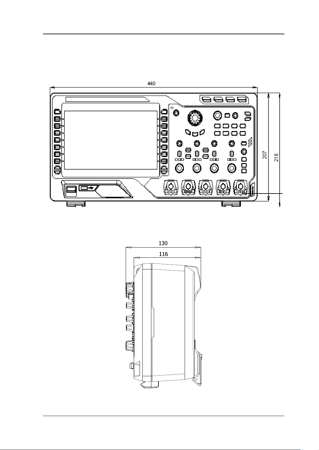
Appearance and Dimensions
Figure 1-1 Front View Unit: mm
Figure 1-2 Side View Unit: mm
DS4000E User’s Guide 1-3
Page 28
RIGOL Chapter 1 Quick Start
To Prepare the Oscilloscope for Use
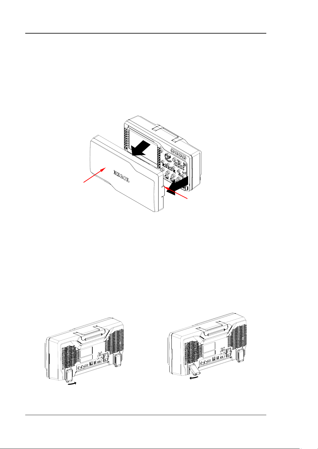
To Remove the Protective Cover
Before using the oscilloscope, remove the front panel cover. Grasp the tran sverse
tabs on each side and pull them outward to remove the cover.
Front Panel Cover
Transverse Tab
Figure 1-3 To Remove the Protective Cover
To Adjust the Supporting Legs
Adjust the supporting legs properly to use them as stands to tilt the oscilloscope
upwards for stable placement of the oscilloscope as well as better operation and
observation. Unfold or fold the supporting legs in the directions of the arrows as
shown in the figures below.
Figure 1-4 To Adjust the Supporting Legs
1-4 DS4000E User’s Guide
Page 29
Chapter 1 Quick Start RIGOL
To Connect to Power Supply
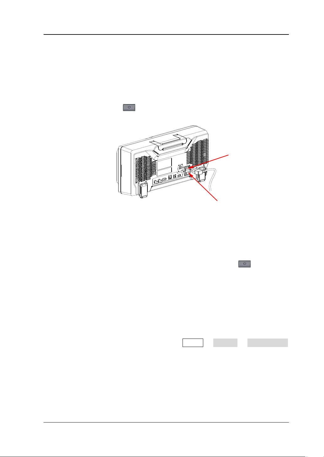
This oscilloscope supports two kinds of AC input power supplies: 100 V-127 V, 45
Hz-440 Hz; 100 V-240 V, 45 Hz-65 Hz. Please use the power cord supplied with the
accessories to connect the oscilloscope to the AC power source, as shown in the
figure below. After you turn on the power switch, the oscilloscope is connected to
power, and the Power key
located at the lower left corner of the front panel is
blinking.
Power Supply Connector
Power Swi t ch
Figure 1-5 To Conne ct to Power Supply
Power-on Inspection
When the oscilloscope is connected to powe r, press the Power key
left corner of the front panel to start the oscilloscope. During the start-up process,
the oscilloscope performs a series of self-tests. You can hear the switching sound of
the relay. After the self-test, the welcome screen is displayed. The "Current Options"
dialog box will be displayed if your instrument currently has installed the trial
versions of the options. From this dialog box, you can view the name, version, and
the remaining trial time of the option currently installed. The instrument will be
installed with the trial versions of the options before lea ving factory. Its remaining
trial time is about 2,000 minutes. Y ou can press Utility System SelfTestInfo
to view the self-test results.
at the lower
DS4000E User’s Guide 1-5
Page 30
RIGOL Chapter 1 Quick Start
To Connect the Probe
RIGOL provides passive and active probes for DS4000E. For detailed technical
information of the probes, please refe r to the corre spondi ng Pro be User’s Guide. The
probes recomm e nded for thi s os ci l lo s c ope are as shown in the table below.
Model Description
RP3300A 350 MHz, passive probe, standard, auto detection
RP7150 1.5 GHz, active probe, optional, auto detection
Besides, DS4000E series oscilloscope also supports TekProbe-BNC 2 degree probes
(with RIGOL T2R1000 interface adaptor, option) of Tektronix.
To Connect the Passive Probe
1. Connect the BNC terminal of the probe to the analog channel input terminal or
external trigger input connector of the oscilloscope at the front panel (please
refer to “Front Panel Overview”).
Figure 1-6 To Connect the Passive Probe
2. Connect the ground alligator clip or ground sp ri ng of the probe to the circuit
ground terminal and connect the probe tip to the circuit point to be tested.
After connecting the passive probe, you need to perform probe function inspection
and probe compensation before making measu rements. F or the detailed steps, refer
to “Passive Probe Function Inspection&Compensation Adjustment”.
1-6 DS4000E User’s Guide
Page 31
Chapter 1 Quick Start RIGOL
To Connect the Active Probe
Take RP7150 (with differential probe front) as an example.
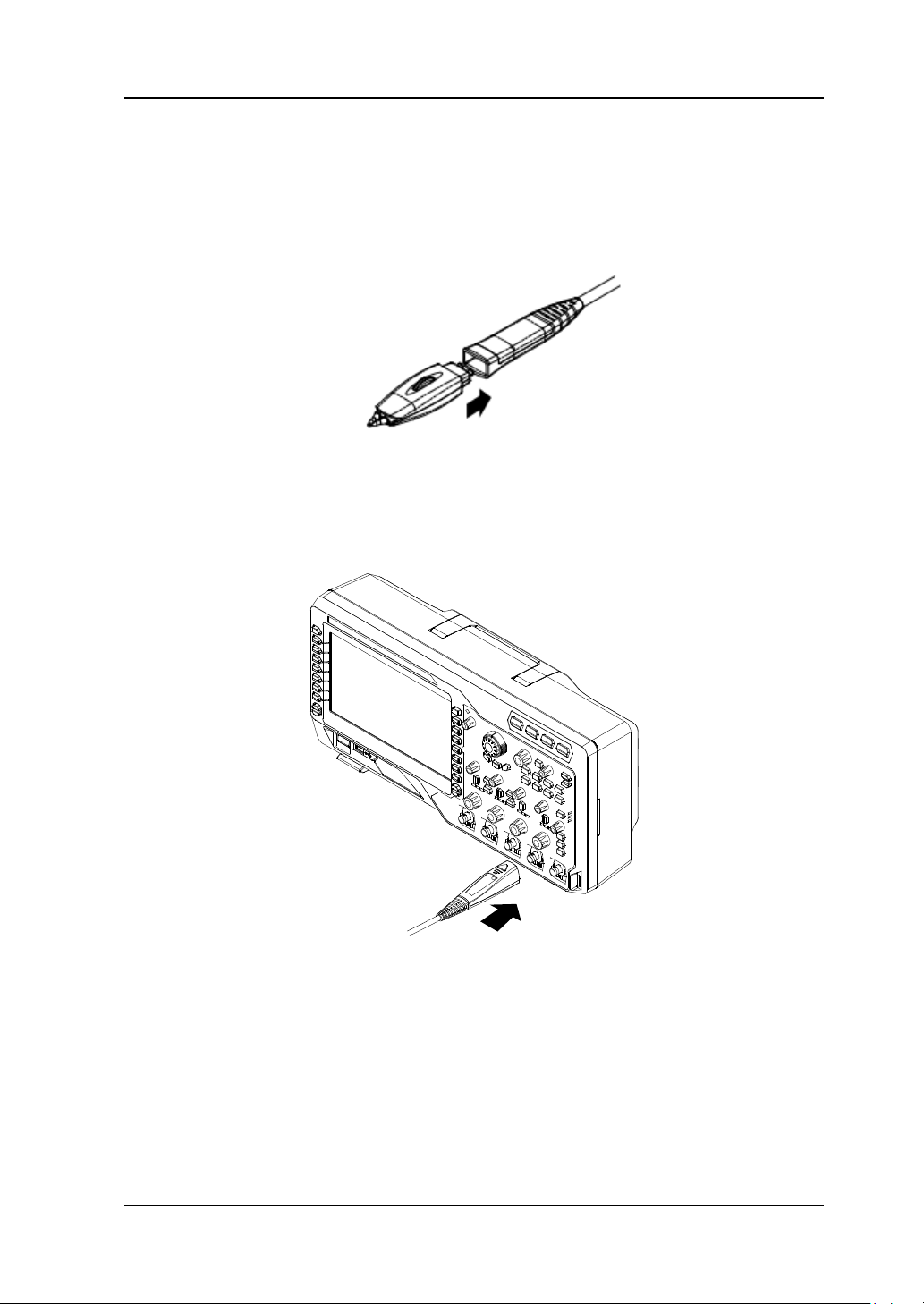
1. Connect the probe front with the active probe amplifier.
2. Connect the other e nd of the active probe a mplifier to the analog channel input
terminal or external trigge r input connecto r of the os cilloscope at the front pane l
(please refer to “Front Panel Overview”). Note that you need to push the
probe to the due position to lock it firmly.
Figure 1-7 To Connect the Active Probe
3. Connect the probe front to the circuit under test using the probe auxiliary
equipment.
After connecting the active probe, you can perform probe calibration and offset
voltage adjustment. For the detailed steps, refer to “Active Probe”.
DS4000E User’s Guide 1-7
Page 32
RIGOL Chapter 1 Quick Start
To Connect the Tek Probe
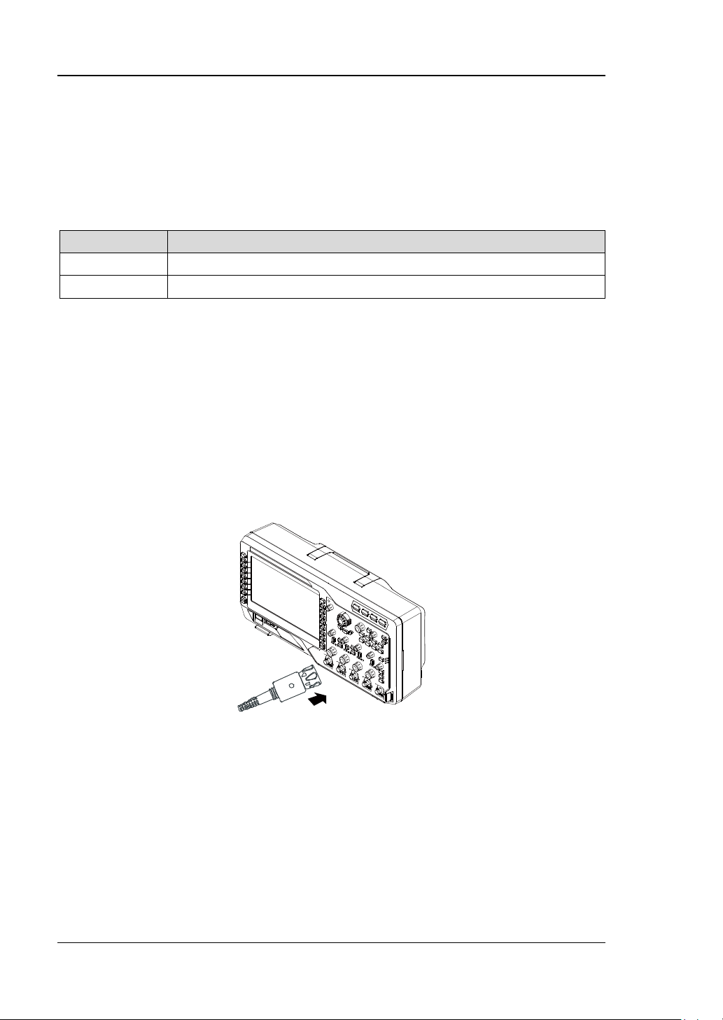
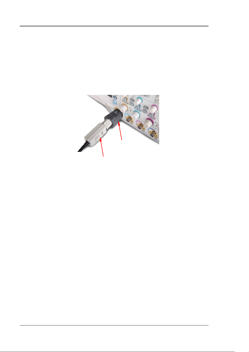
1. Connect the Tek probe to one end of T2R1000 adaptor correctly.
2. Connect the other end o f T2R1000 adaptor to the analog channel inp ut terminal
or external trigger input connector (refer to “Front Panel Overview”) of
DS4000E series oscilloscope at the front panel correctly.
T2R1000
Tektronix Probe
Figure 1-8 To Connect the Tek Probe
3. Connect the ground terminal of Tek probe to the ground terminal of the circuit.
Connect the probe tip of Tek probe to the test point of the circuit under test.
For the specified model of Tek probe, you can perform probe calibration and offset
voltage adjustment after the probe is connected. For the details, refer to “Tek
Probe”.
1-8 DS4000E User’s Guide
Page 33
Chapter 1 Quick Start RIGOL
Passive Probe Function Inspection&Compensation Adjustment
After connecting the passive probe, you need to perform probe function inspection
and probe compensation before making measurements.
Function Inspection
You need to perform probe function inspection according to the steps below before
making measurements using the passive probe.
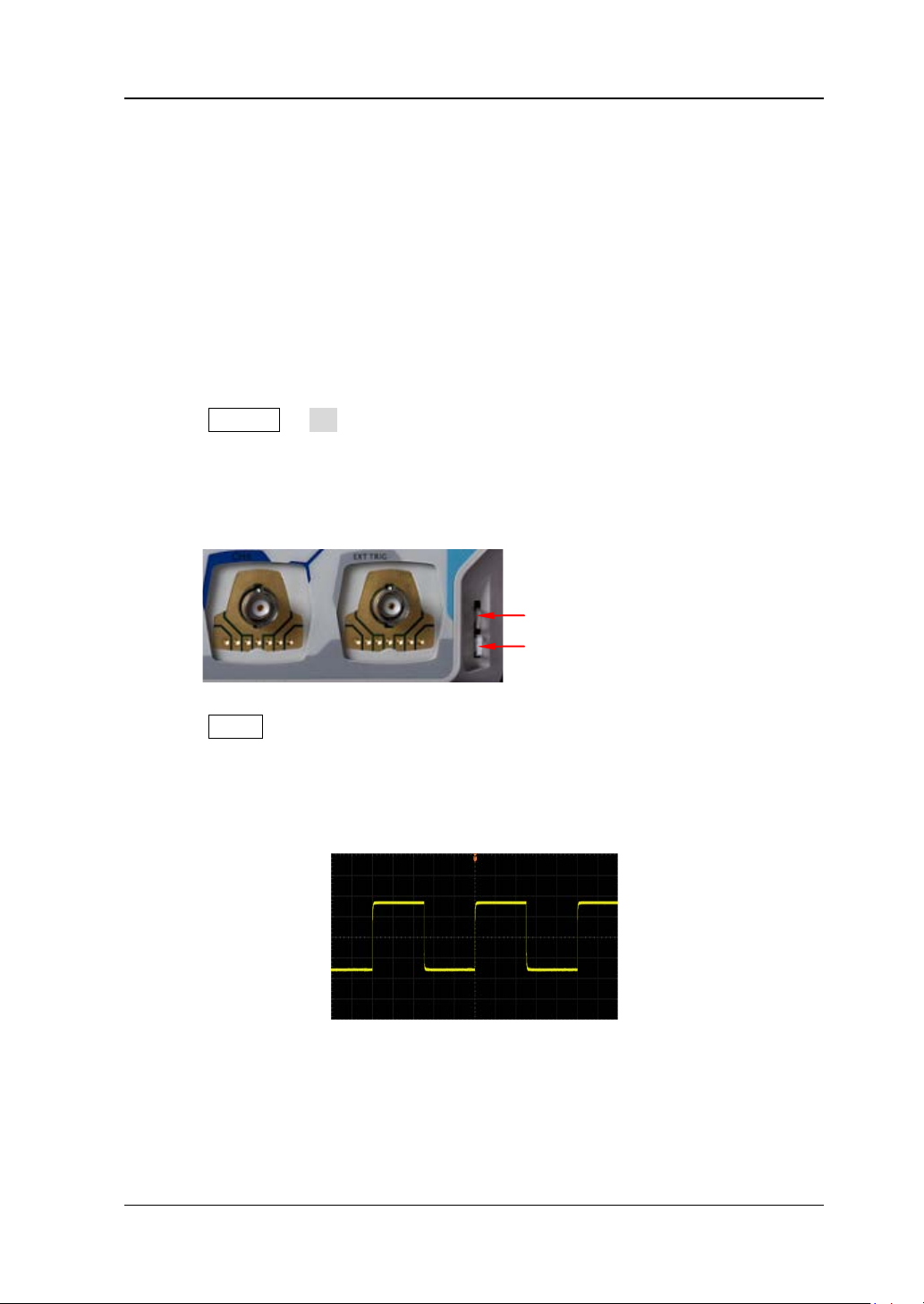
1. Press Default OK to restore the oscilloscope to the factory setting.
2. Connect the ground all igator clip of t he probe to the “Ground Terminal” as shown
in Figure 1-9.
3. Use the probe to connect the input terminal of CH1 of the oscilloscope and the
“Compensation Signal Output Terminal” of the probe as shown in Figure 1-9.
Compensation Signal Output Terminal
Ground Terminal
Figure 1-9 To Use the Co mpensation Signal
4. Press AUTO.
5. Observe the wa vef orm o n the dis play. In normal condition, the display s hould be
a square waveform as shown in the figure below. If the square waveform
actually shown does not match that in the figure below, please perform “Probe
Compensation” in the next section.
Figure 1-10 Probe Compensation Signal (Square Waveform)
6. Use the same method to test the other channels.
DS4000E User’s Guide 1-9
Page 34
RIGOL Chapter 1 Quick Start
WARNING
To avoi d electric shock , please mak e sure that the in sulated wire of the
probe is in good condition and do not touch the metallic part of the
probe when the probe is connected to a high voltage source.
Tip
The probe compensation signal can only be used for probe compensation
adjustment and cannot be used for calibration.
Probe Compensation
When the probes are used for the first time or when the probe compensation signal
does not match that shown in Figure 1-10 (refer to “Function Inspection”), you
should compensate the probes to match the input channels of the oscilloscope.
Non-compensated or poorly compensated probes may cause meas ureme nt error.
The probe compensation procedures are as follows.
1. Perform steps 1, 2, 3 and 4 of “Function Inspection” in the previous section.
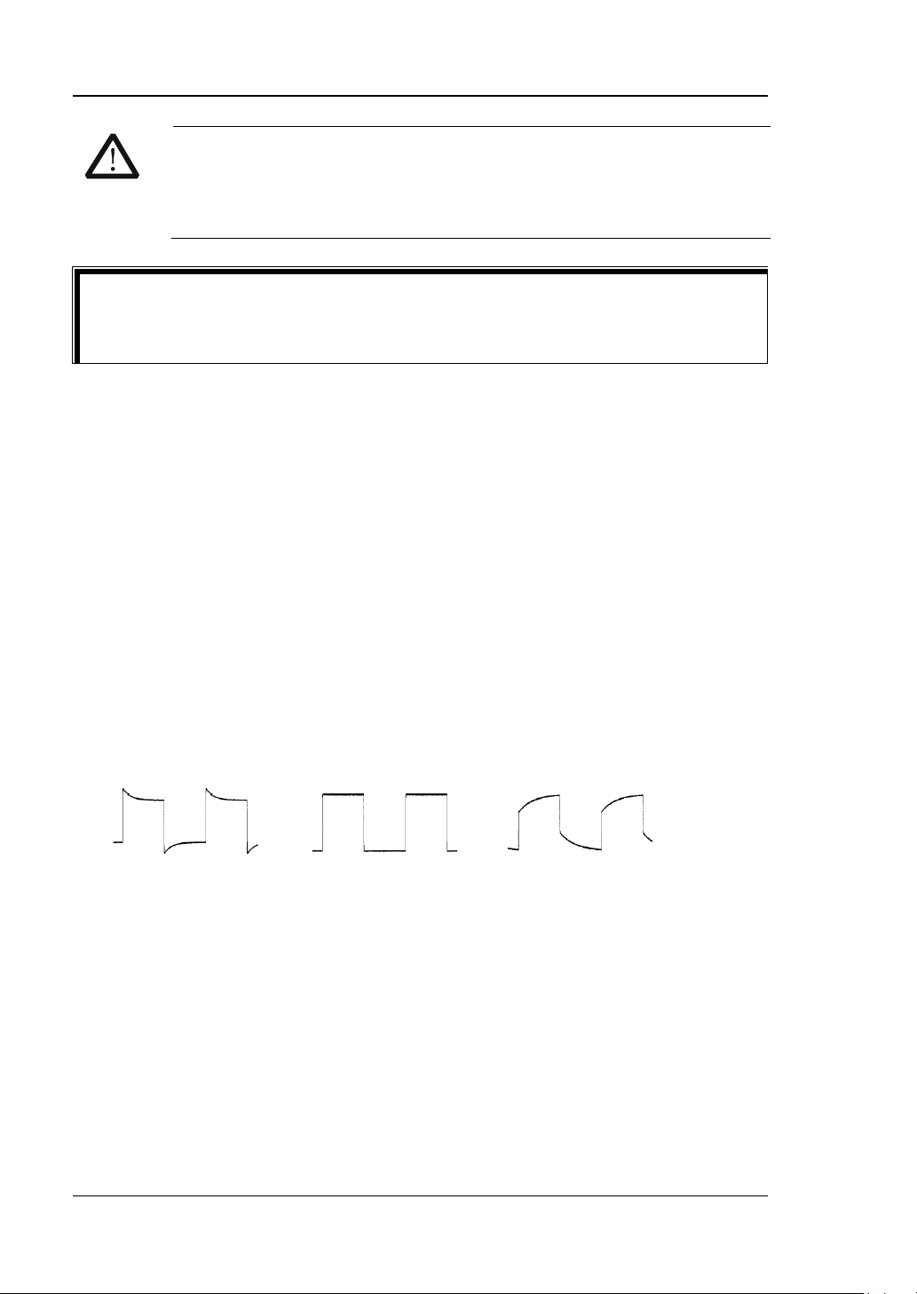
2. Check the waveform displayed on the oscilloscope and compare it with the
waveforms shown in the figure below.
Over compensated Perfectly compensated Under compensated
Figure 1-11 Probe Compensation
3. Use a nonmetallic driver to adjust the low-frequency compensation adjustment
hole on the probe until the waveform displayed is as t he “Perfe ctly compensated”
in the figure above.
1-10 DS4000E User’s Guide
Page 35
Chapter 1 Quick Start RIGOL
Front Panel Overview
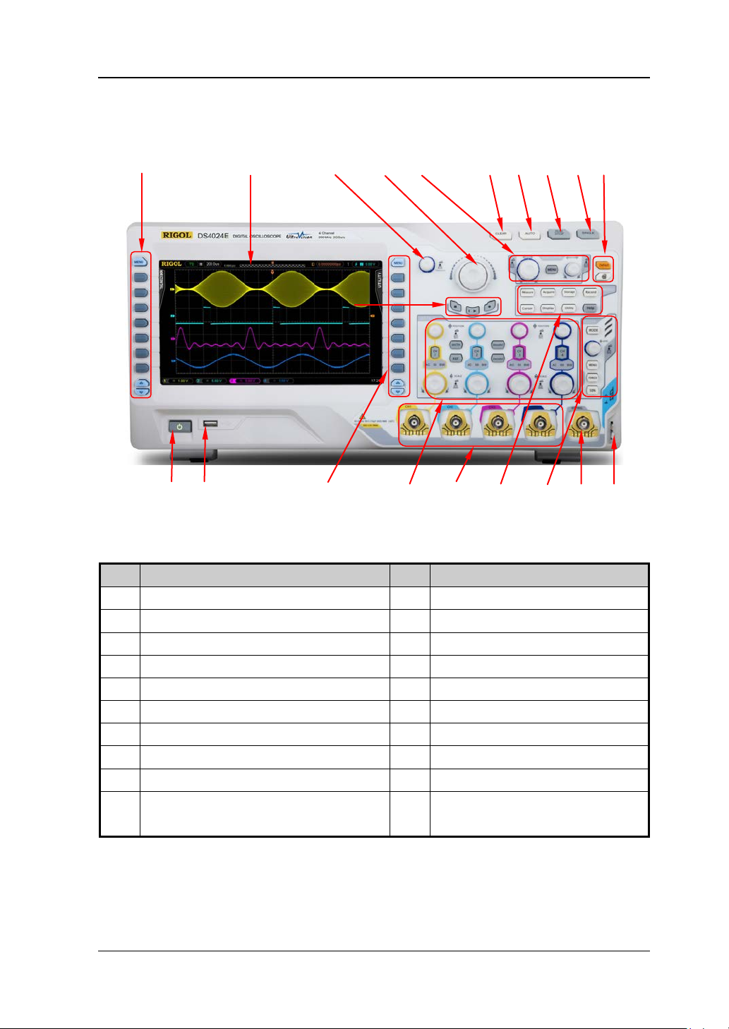
3 4 5
6 7 8 9 10 1 2
11
12 13 14 15 16 17 18 19 20
Figure 1-12 Front Panel Overview
Table 1-1 Front Panel Description
No. Description No. Description
1 Parameters Measurement Menu Softkeys 11 Record
2 LCD 12 Power Key
3 Multi-function Knob 13 USB HOST
4 Navigation Knob 14 Function Setting Menu Softkeys
5 HORIZONTAL 15 VERTICAL
6 CLEAR 16 Channel Input Termina ls
7 AUTO 17 Function Keys
8 RUN/STOP 18 TRIGGER
9 SINGLE 19 EXT TRIG Input Terminal
10 Default and Print 20 Probe Compensation Signal Output
Terminal and Ground Terminal
DS4000E User’s Guide 1-11
Page 36
RIGOL Chapter 1 Quick Start
Rear Panel Overview
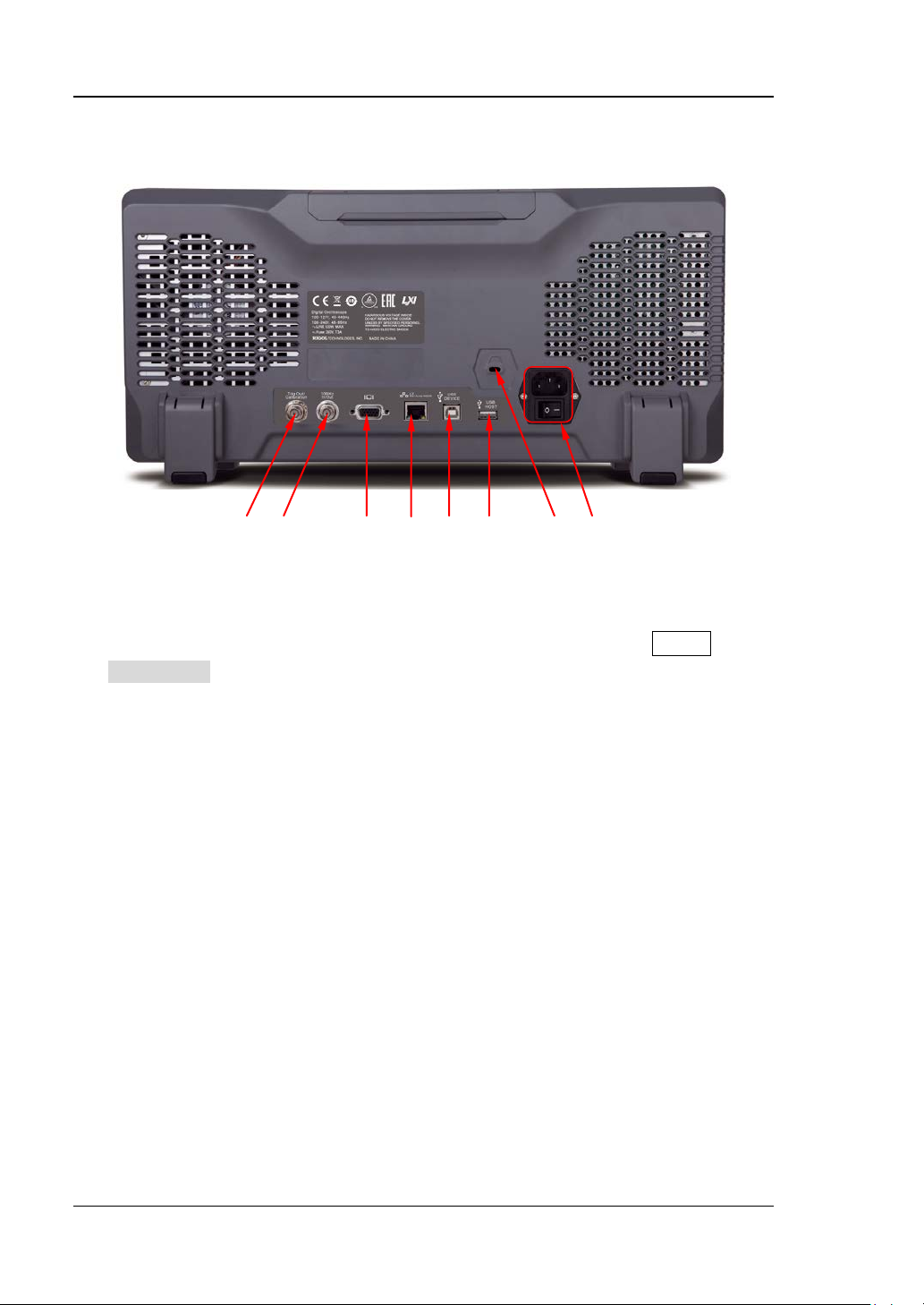
1. Trig Out/Ca libration
Various kinds of signals can be output from this connector (press Utility
AuxOutput to select the desired output type).
1) TrigOut: the oscilloscope outputs a signal that can reflect the current
capture rate of the instrument each time a trigger is generated. Connect the
signal to a waveform display device and measure the frequency of the signal;
the measurement result is the same as the current capture rate.
2) Fast: the oscilloscope out puts a fast edge signal with 5 00 ps rise time from
this connector and the signal can be used in the self-calibration of the
oscilloscope.
3) GND: the oscilloscope outputs a ground level from this connector.
4) PassFail: the os cilloscope outputs a TTL high level when a failed waveform
is detected until the curre nt f ra me of wa v efo rm is finished and then outputs
a low level at the beginning of the next frame of waveform. This signal can
be transmitted to other control syste m for easy view of the test result.
2. Reference Clock
A more precise sample clock signal can be provided for the oscilloscope with the
reference clock. It can also be used to synchronize the clocks of two or more
oscilloscopes.
1 2 3 4 5 6 7 8
Figure 1-13 Rear Panel Overview
1-12 DS4000E User’s Guide
Page 37

Chapter 1 Quick Start RIGOL
3. Video Output
Through this interface, t he os cillosco pe can be connected to an external monitor
for clearer waveform d isplay. At this point, the display of the oscilloscope is still
operational.
4. LAN
Through this interface, the oscilloscope can be connected to the local are a
network for remote control. This oscilloscope conforms to LXI-C standard and
can quickly build test system with other devices.
5. USB DEVICE
Through this interface , the oscillos cope can be conne cted to PictBridge printer to
perform the print operation or PC to control the oscilloscope remotely.
6. USB HOST
You can connect a USB storage device via this interface to perform external
storage and recall. You can also extend a GPIB interface via this interface using
the USB-GPIB interface converter (optional) provided by RIGOL to realize GPIB
communication.
Note: There is also a USB HOST interface at the front panel.
7. Lock Hole
Use a security lock (available separately) to lock the oscilloscope to a fixed
location via this lock hole.
8. AC Power Socket/Power Switch
AC power input terminal. This oscilloscope accepts two kinds of AC power
supplies: 100 V-127 V, 45 Hz-440 Hz and 100 V-240 V, 45 Hz-65 Hz. For the
power connection method, refer to “To Connect to Power Supply”.
DS4000E User’s Guide 1-13
Page 38
RIGOL Chapter 1 Quick Start
Front Panel Function Overview
VERTICAL
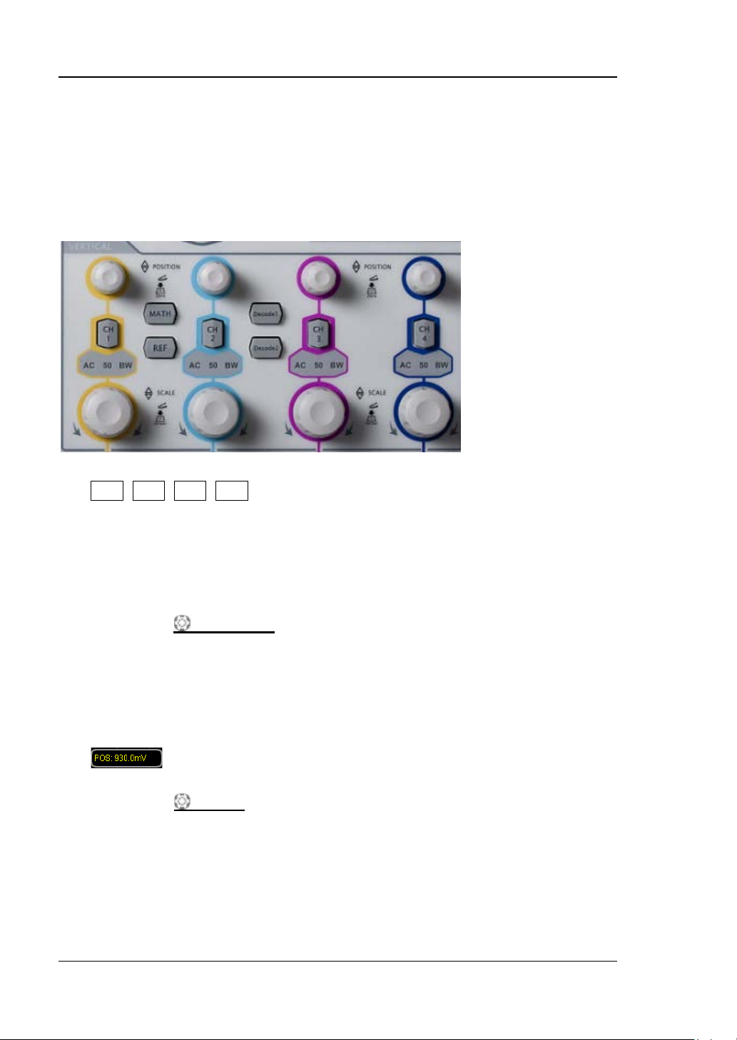
DS4000E provides an independen t v ertical co ntrol syste m for each input channel.
CH1, CH2, CH3, CH4: input channel switches.
The four channels are marked by different colors which are also used to mark
the corresponding waveforms on the screen and the channel input connecto rs.
Press any key to turn on the corresponding channel and open the cor responding
channel menu; press again to turn off the channel.
VERTICAL
Turn the knob to modify the vertical position of the corresponding channel
waveform. During the modification, the wavef orm of the corresponding channel
moves up and down; the vertical position information (as shown in the figure
below) pops up at the lower-left side of the screen in real-time. Pressing down
the knob can quickly reset the vertical position (zero).
POSITION: channel vertical position knobs.
VERTICAL
Turn the knob to modify the vertical scale of the corresponding channel
waveform. During the modification, the waveform of the corresponding channel
is expanded or compressed vertically (the actual amplitude keeps unchaged);
the vertical scale information (as shown in the figure below) at the bottom of the
screen changes accordingly. Pressing down the knob can quickly switch the
1-14 DS4000E User’s Guide
SCALE: channel vertical scale knobs.
Page 39
Chapter 1 Quick Start RIGOL
vertical scale adjustment mode between “Coarse” and “Fine”.
MATH: press this key to open the math operation function menu. You can
perform addition, subtraction, multiplication, division, FFT, digital filter, logic
operations and advanced operations.
REF: press this key to e nable th e r eferenc e wav eform function. You can
compare the waveform actually measured with the reference waveform.
Decode1, Decode2: press any key to open the corresponding decoding
function menu. DS4000E supports parallel decoding and various protocol
decodings (for more details, refer to “
Protocol Decoding”).
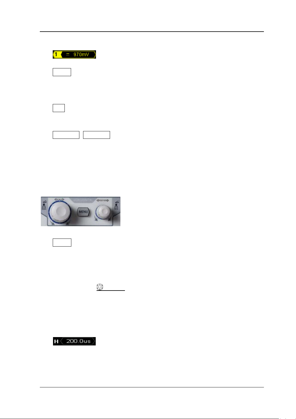
HORIZONTAL
MENU: press this key to open the horizontal control menu. You can turn on or
off the delayed sweep, switch between different horizontal time base modes,
switch between “Coarse” and “Fine” adjustments of the horizontal time base as
well as modify the horizontal reference setting.
HORIZONTAL SCALE: horizontal scale knob.
Turn th e kn ob to modify the horizontal time base. During the modification, the
waveform s displayed are expanded or compressed horizontally; the horizontal
time base message (as shown in the figure below) at the upper-left side o f the
screen changes accordingly. Pressing down the knob can quickly turn on or off
the delayed sweep.
When delayed sweep is turned on, turning the knob can modify the delayed
sweep time base. During the modification, the delayed sweep waveform is
expanded or com p re s s ed horizontally; the delayed sweep time base message
DS4000E User’s Guide 1-15
Page 40
RIGOL Chapter 1 Quick Start
(as shown in the figure below) at the middle of the s c reen c hanges accordingly.
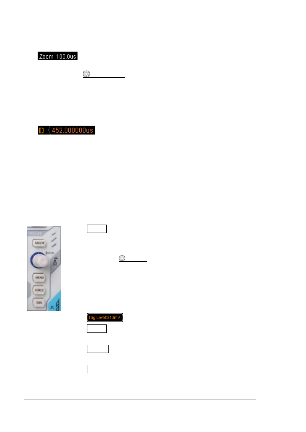
HORIZONTAL
POSITION: horizontal position knob.
Turn th e kn ob to modify the horizontal position (namely the trigger position).
During the modification, the trigger point and the waveforms displayed move
left or right; the horizontal position message (as shown in the figure below) at
the upper -right side of the screen changes accordingly. Pressing down the knob
can quickly reset the horizontal position (zero).
When delayed sweep is turned on, turning the knob can modify the delayed
sweep horizontal position. During the modification, the delayed sweep trigger
point and waveform move left or right; the delayed sweep horizontal position
message (as shown in the figure above) at the upper-right side of the screen
changes accordingly.
TRIGGER
MODE: press this key to switch the trigger mode to “Auto”,
“Normal” or “Single” and the corresponding status backlight
of the current trigger mode would be illuminated.
TRIGGER LEVEL: trigger level knob.
Turn the knob to modify the trigger level. During the
modification, the trigger level line moves up and down; the
trigger level message (as shown in the figure below) pops up
at the lower-left side of the screen in real-time. Pressing
down the k nob can quickly reset the trigger level to 0.
MENU: press this key to open the trigger operation menu.
This oscilloscope provides various trigger types.
FORCE: in Normal and Single trigger modes, press this key
to generate a trigger signal forcibly.
50%: press this key to set the trigger level to the vertical
midpoint of the trigger signal amplitude.
1-16 DS4000E User’s Guide
Page 41
Chapter 1 Quick Start RIGOL
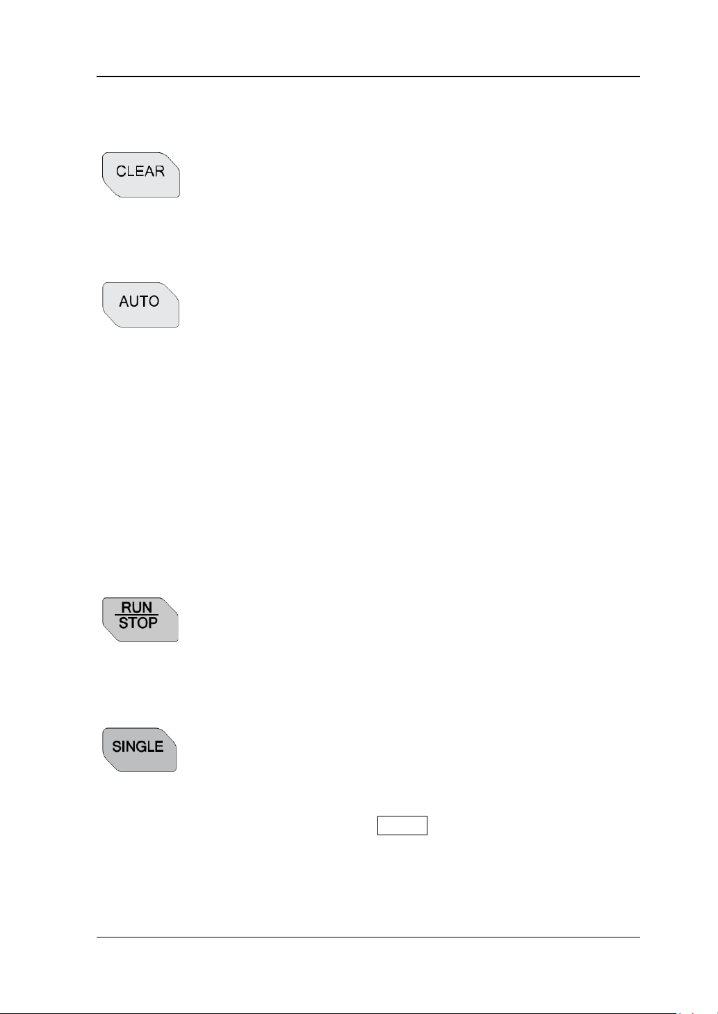
CLEAR
Press this key to clea r all the w a vef orms on the s creen. If the
oscilloscope is in “RUN” state, new waveforms w ill be
displayed.
AUTO
Press this key to en able the waveform auto setting function.
The oscilloscope will automatically adjust the vertical scale,
horizontal time base, trigger mode and so on according to the
input signal to realize optimum waveform display. Besides,
the quick parameter measurement function is also provided
(for more details, refer to “Quick Measurement after
AUTO”).
Note: The waveform auto setting function requires that the
frequency of sine should be no lower than 20 Hz, the duty
cycle is greater than 1% and the amplitude is 20 mVpp at
least. If the parameter exceeds this limit, the waveform auto
setting function might be invalid.
RUN/STOP
Press this key to set the state of the oscilloscope to “RUN” or
“STOP”. In “RUN” state, the key is illuminated in yellow and
red in “STOP” state.
SINGLE
Press this key to set the trigger mode to “Single”. In single
trigger mode, the oscilloscope generates a trigger when the
trigger conditions are met and then stops. When the
oscilloscope is in wait-for-trigger state (the key is illuminated
in orange), pressing FORCE will generate a trigger signal
immediately.
DS4000E User’s Guide 1-17
Page 42
RIGOL Chapter 1 Quick Start
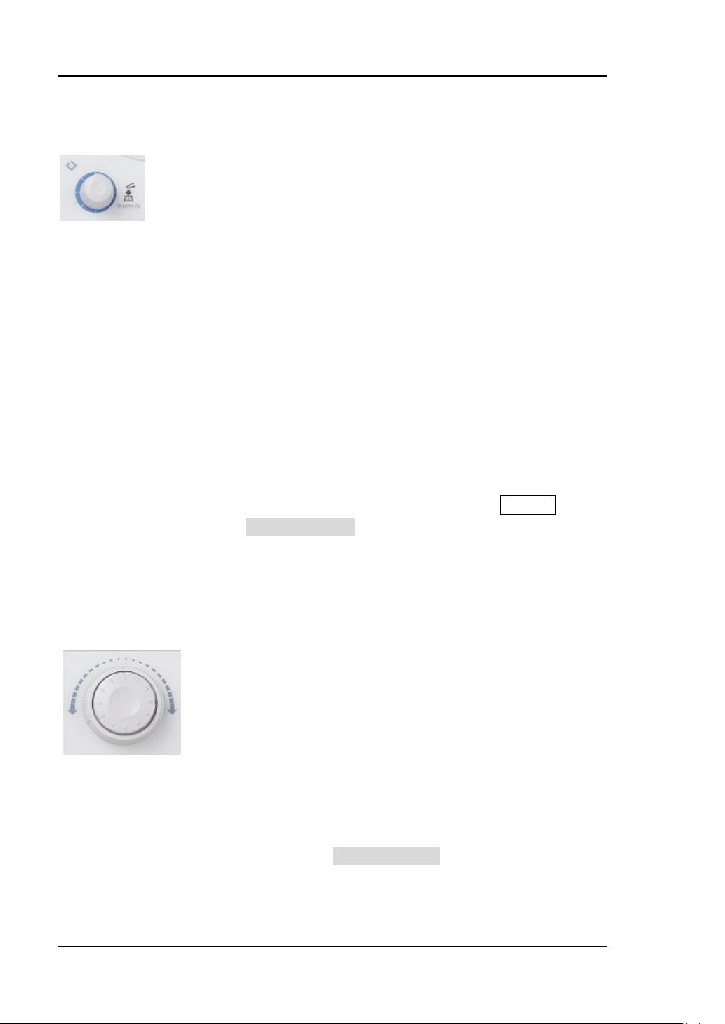
Multi-function Knob
This knob can be used to select parameter item, adjust the
value of the parameter and etc.
In menu operation, this knob can be used to open the
submenu or select the desired parameter item. For
menu item that include multiple parameter items, you
can press the corresponding menu softkey and then
turn the knob to select the specified parameter item
(sometimes, you need to press down the knob to se lect
the parameter item). This knob can also be used to
modify the parameter, input fielname and etc.
In non-menu operation (the menu is hidden), turning
the knob can adjust th e waveform brightness. The
adjustable range is from 0% to 100%. Turn the knob
clockwise to increase the waveform brightness and
counterclockwise to decrease the waveform brightness.
Pressing down the knob can quickly reset the wa vefor m
brightness to 50%. You can also press Display
WaveIntensity and then turn the knob to adjust the
waveform brightness.
Navigation Knob
This knob provides quick adjust/locate function for
numerical parameters wit h relativel y la rger settable ranges.
Turn the knob clockwise to increase the value and
counterclockwise to decrease the value. The inner knob is
used for fine adjustment and the outer knob for coarse
adjustment (the larger the rotation amplitude of the outer
knob is, the faster the change speed of the value will be).
For example, this knob can be used to quickly locate the
waveform frame (Curr ent Frame) to be played back in
waveform p l ay back. Similar parameters include trigger
holdoff, pulse width setting, slope time and etc.
1-18 DS4000E User’s Guide
Page 43
Chapter 1 Quick Start RIGOL
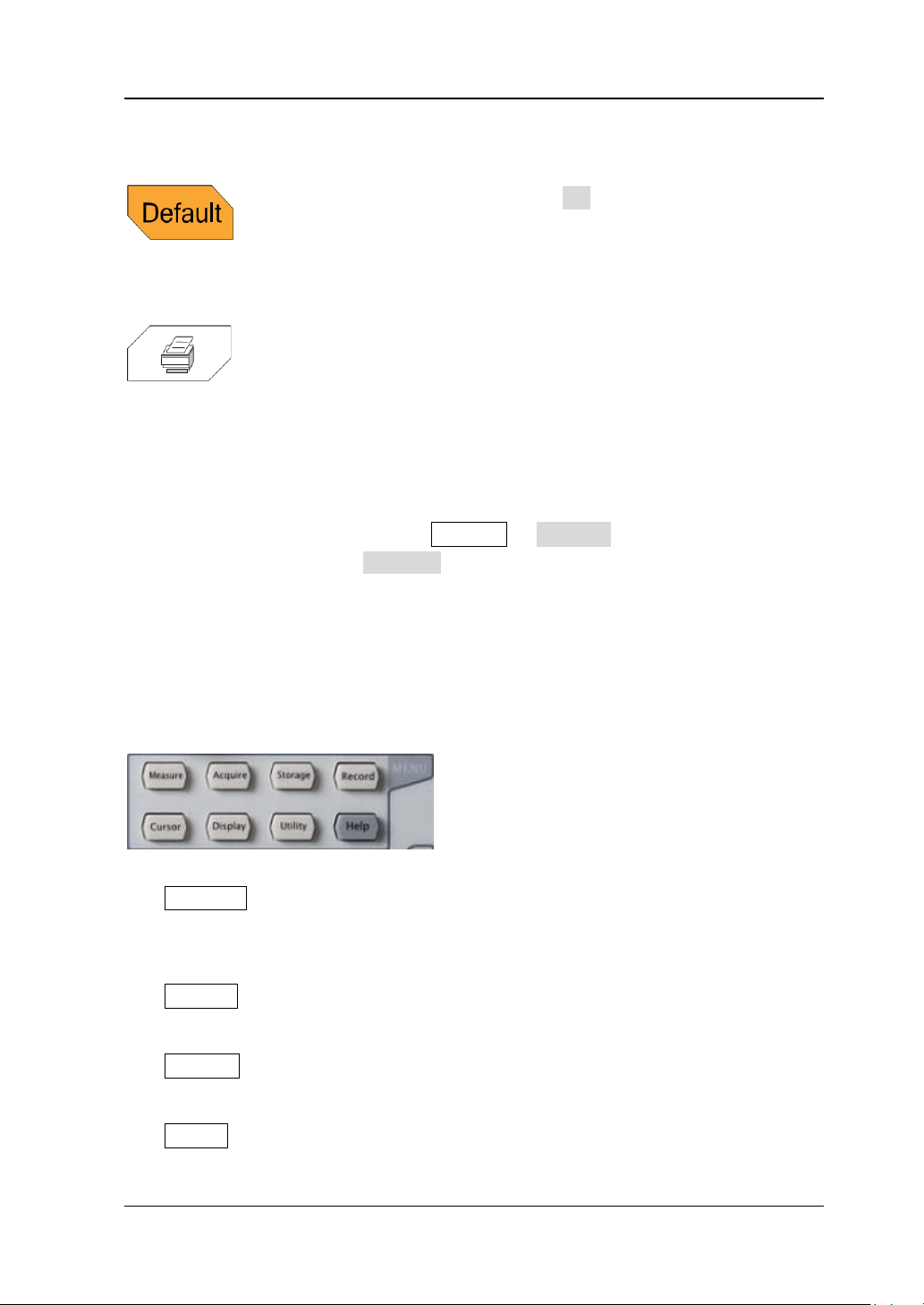
Default
Press this key and then press OK to restore the oscilloscope
to its factory setting (please refer to
Table 12-2).
Press this key to e xe cute t he print f u nction or sa ve t he s creen
content in a USB storage device as a picture file. If the
oscilloscope is currently connected to a PictBridge printer and
the printer is in idle state, pressing this key will execute the
print function. If no printer but a USB stor age device is
currently connected, pressing this key will save the screen
content to the USB storage device in the specified picture
format (press Storage Storage and select “Picture”;
press Pic Type and select “*.bmp” , “*.png”, “*.jpeg” or “tiff”;
the default is “png”). When PictBridge printer and USB
storage device are connected at the same time, the PictBridge
printer enjoys higher priority.
Function Keys
Measure: press this key to enter the measurement setting menu. You can set
the signal source, perform all measu rement, turn on the statistic function, make
measurement settings and so on.
Acquire: press this key to enter the sample setting menu. You can set the
acquisition mode, memory depth and anti-aliasing function of the oscilloscope.
Storage: press this key to enter the file store and recall interface. This
instrument supports internal/external storage as well as disk management.
Cursor: press this key to enter the cursor measurement menu. The oscilloscope
provides four cursor modes (manual, track, auto and X-Y).
DS4000E User’s Guide 1-19
Page 44
RIGOL Chapter 1 Quick Start
Note: The X-Y cursor mode is only available when the horizontal time base
mode is X-Y.
Display: press this key to enter the display setting menu. You can s et th e
waveform display type, persistence time, waveform intensity, screen grid type,
grid brightnes s and menu dis pl ay time.
Utility: press this key to enter the system auxiliary function setting menu. You
can set the system-related functions and parameters, such as the I/O setting,
sound and language. The oscilloscope also supports some advanced functions,
such as the pass/fail test and print setting.
Record: press this key to enter the waveform recording menu. You can select
the desired wa veform rec ording mode and set the related parameters.
Help: press this key to open the help interface. For the detailed information,
please refer to the introduction in “To Use the Built-in Help System”.
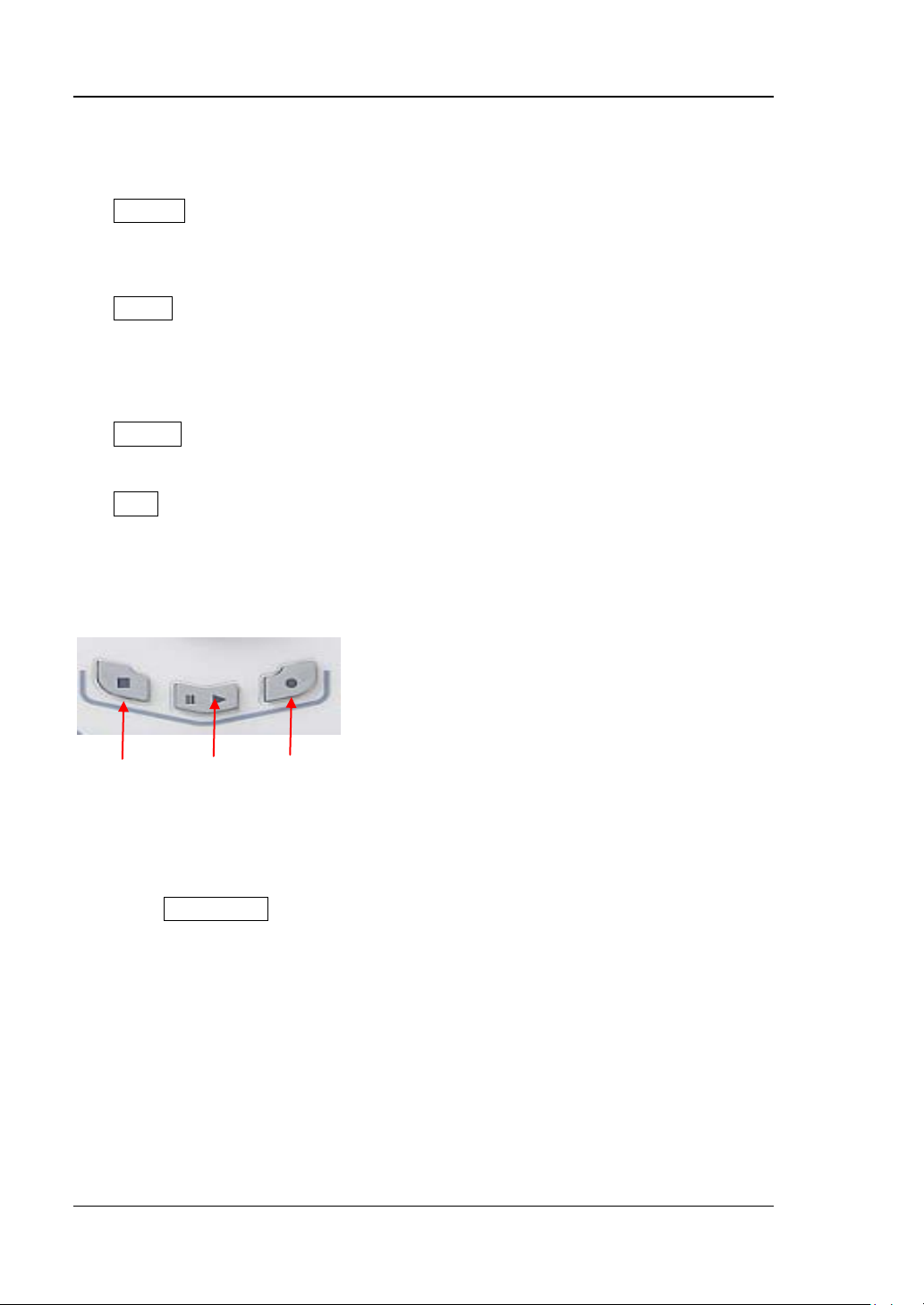
Record
Stop Play/Pause Record
Record: press this key to sta rt recording the wavefor m. The backlight is
illuminated in red and flashes. Besides, the backlight will also be illuminated in
red and flashes when the open mode (record constant on) is enabled until you
press RUN/STOP to stop the waveform recording.
Stop: press this key to stop the waveform recording or waveform playback. The
backlight is illuminated in orange . Besides, the backlight will also be illuminated
in orange when the waveform recording or waveform playback finishes.
Play/Pause: when the waveform recording is stopped or when the waveform
palyback is s t opped or paused, pressing this key to start playing back the
waveform; the backlight is illuminated in yellow and flashes. Pressing this key
again to pause the playback; the backlight is illuminated in yellow.
1-20 DS4000E User’s Guide
Page 45
Chapter 1 Quick Start RIGOL
User Interface
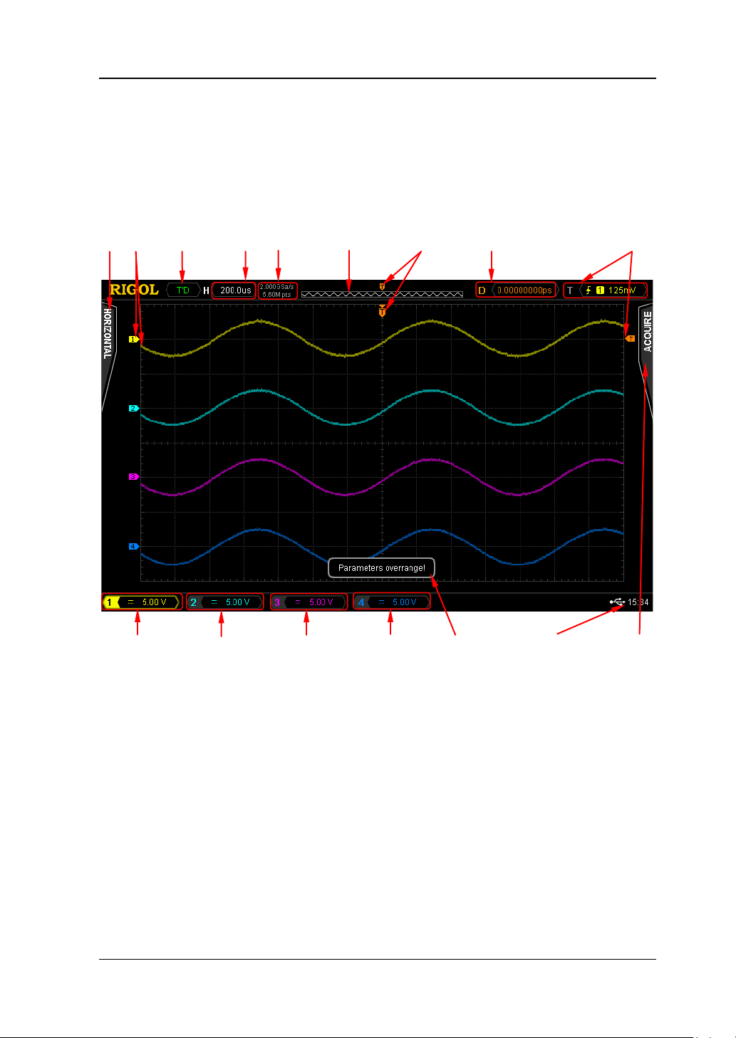
The user interface of DS4000E series oscilloscope is as shown in Figure 1-14 and
Table 1-2.
1 2 3 4 5 6 7 8 9
10 11 12 13 14 15 16
Figure 1-14 User Interface
DS4000E User’s Guide 1-21
Page 46
RIGOL Chapter 1 Quick Start
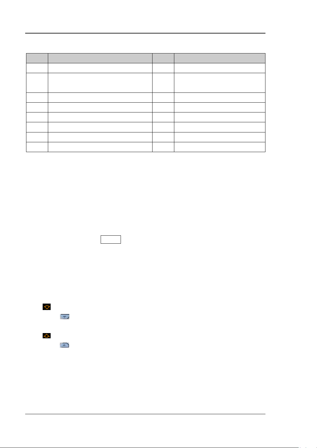
Table 1-2 User Interface Overview
No. Name No. Name
1 Auto Measurement Items 9 Trigger Setting
2 Analog Channel Label and
10 CH1 Status Label
Waveform
3 Status 11 CH2 Status Label
4 Horizontal Time Base 12 CH3 Status Label
5 Sample Rate and Memory Depth 13 CH4 Status Label
6 Wave form Memory 14 Messag e Box
7 Trigger Position 15 Notification Area
8 Horizontal Position 16 Function Setting Menu
Tip: Table 1-2 is the user interf ace ove rview table. Y ou ca n click the number or name
to quickly move to the corresponding content.
In the following part, detailed introductions are provided on the user interface
accoding to the numbering sequence in Figure 1-14.
1. Auto Measurement Items
Provide 16 horizontal (HORIZONTAL) and 13 vertical (V ERT I CAL) measurement
parameters. Pressing MENU at the left of the screen can unfold the horizontal
measurement menu or the vertical measurement menu or fold the
measurement menu. When the measurement menu is unfolded, pressing the
measurement menu softkey at the left of the screen can activate the auto
measurement function of the corres ponding par ameter.
Note: When the measurement menu is unfolded, the following labels may be
displayed in the grid at the lower-left side of the sc reen.
Denote that the current menu includes multiple pages. You can press
(the page down key) at the left of the screen to open the next page
of menu.
Denote that the current menu includes multiple pages. You can press
(the page up key) at the left of the sc reen to open the previous page
of menu.
2. Analog Channel Label and Waveform
Different channels are marked in different colors. The channel label and
wavef orm are marked in the same color as the analog channel.
1-22 DS4000E User’s Guide
Page 47
Chapter 1 Quick Start RIGOL
3. Status
Available statuses include RUN, STOP, T’D (triggered), WAIT and AUTO.
4. Horizontal Time Base
Represen t the time per grid on the horizontal axis on the screen.
Use HORIZONTAL
SCALE to modify this parameter. For different
models, the adjustable ranges of the horizontal time base are different
(please refer to
Table 3-1).
5. Sample Rate and Memory Depth
Display the current sample rate and memory depth.
Modifying the horizontal time base (use HORIZONTAL SCALE) might
modify the sample rate and/or memory depth indirectly. You are not
allowed to modify the sampler rate directly.
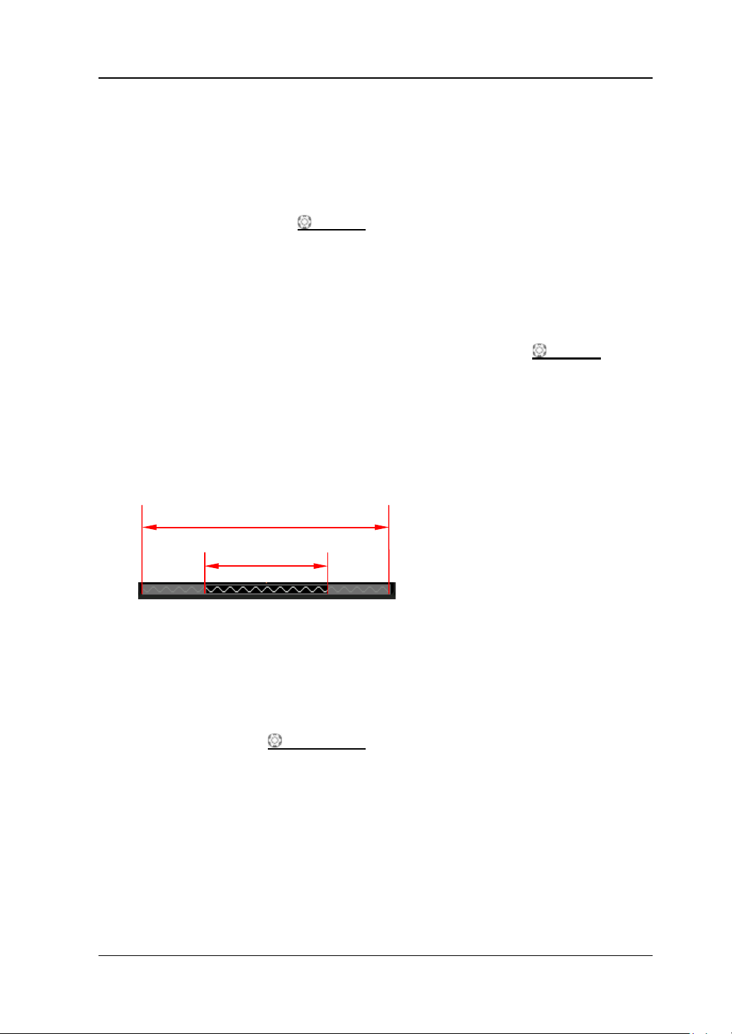
6. Waveform Memory
Provide t he schematic diagram of the memory position of the waveform
currently on the screen in the memory.
Wavef orm in the Memory
Waveform on the Screen
7. Trigger Position
Display the trigger positions of the waveform in the waveform memory and on
the screen.
8. Horizontal Position
Use HORIZONTAL
POSITION to modify this parameter. Pressing down
the knob can quickly reset the horizontal position (zero).
9. Trigger Setting
The trigger setting information includes trigger type, trigger source and trigger
level (may also include trigger level labe l ).
Trigger Type
Display the t ri gge r t ype currently selected and the trigger c ondition set ting.
Different label is displayed when different trigger type is selected. For
DS4000E User’s Guide 1-23
Page 48
RIGOL Chapter 1 Quick Start
example, represents triggering on the rising edge in “Edge Trigger”.
Trigger Source
Display the trigger source (CH1 to CH4, EXT, EXT/5 or AC Line) currently
selected. Different label is displayed when different trigger source is
selected and the color of the parameters in the trigger setting information
corresponds to the trigger source currently selected. For examp le,
denotes that CH1 is selected as the trigger source.
Trigger Level
― When the trigger source is CH1 to CH4, the trigger level value is
displayed and the trigger level label
is displayed at the right of the
screen.
Note: For runt trigger and slope trigger, you need to set the trigger
level upper limit and trigger level lower limit. The difference between
the current upper limit and lower limit of the trigger leve l is displayed in
the trigger setting inf ormation and two trigger level labels (
and )
are displayed at the right of the screen.
― When the trigger source is EXT or EXT/5, the trigger level value is
displayed and there is no trigger level label.
― When the trigger source is AC line, there is no trigger level.
― You can use TRIGGER
LEVEL to adjsut the trigger level.
10. CH1 Status Label
Display the on/off status of CH1. When it is on, the status label is
highlighted.
Display the vertical scale of CH1 (namely the voltage value per grid of the
CH1 waveform in the vertical direction). Y ou can use VIRTICAL
SCALE
under CH1 to modify this parameter.
Different labels may be displayed according to the current channel setting.
For ex ample,
Specify the Channel Coupling”) is AC;
is displayed when the channel coupling (refer to “To
is displayed when the
bandwidth limit (refer to “To Specify the Bandwidth Limit”) is enabled;
is displayed when the input impedance (refer to “To Specify the Input
Impedance”) is 50 Ω.
11. CH2 Status Label
Display the on/off status of CH2. When it is on, the status label is
highlighted.
1-24 DS4000E User’s Guide
Page 49
Chapter 1 Quick Start RIGOL
Display the vertical scale of CH2 (namely the voltage value per grid of the
CH2 waveform i n the vertical di rection). Y ou can use VIRTICAL
SCALE
under CH2 to modify this parameter.
Different labels may be displayed according to the current channel setting.
For ex ample,
Specify the Channel Coupling”) is AC;
is displayed when the channel coupling (refer to “To
is displayed when the
bandwidth limit (refer to “To Specify the Bandwidth Limit”) is enabled;
is displayed when the inp ut impedance (refer to “To Specify the Input
Impedance”) is 50 Ω.
12. CH3 Status Label
Display the on/off status of CH3. When it is on, the status label is
highlighted.
Display the vertical scale of CH3 (namely the voltage value per grid of the
CH3 waveform i n the vertical direction) . Yo u can use VIRTICAL
SCALE
under CH3 to modify this parameter.
Different labels may be displayed according to the current channel setting.
For ex ample,
Specify the Channel Coupling”) is AC;
is displayed when the channel coupling (refer to “To
is displayed when the
bandwidth limit (refer to “To Specify the Bandwidth Limit”) is enabled;
is displayed when the i nput impe dance (refer t o “To Specify the Input
Impedance”) is 50 Ω.
13. CH4 Status Label
Display the on/off status of CH4. When it is on, the status label is
highlighted.
Display the vertical scale of CH4 (namely the voltage value per grid of the
CH4 waveform i n the vertical direction) . Yo u can use VIRTICAL
SCALE
under CH4 to modify this parameter.
Different labels may be displayed according to the current channel setting.
For ex ample,
Specify the Channel Coupling”) is AC;
is displayed when the channel coupling (refer to “To
is displayed when the
bandwidth limit (refer to “To Specify the Bandwidth Limit”) is enabled;
is displayed when the input im pedance (refer t o “To Specify the Input
Impedance”) is 50 Ω.
DS4000E User’s Guide 1-25
Page 50
RIGOL Chapter 1 Quick Start
14. Message Box
Display the prompt messages.
15. Notification Area
Display the system time, sound icon, USB storage device icon and PictBridge
printer icon.
System Time: displayed in “hh:mm (hour:minute)” format. When printing
or storing the waveform, the output file will contain this time information.
Press Utility System System Time System Time to set the
system time in the following format.
yyyy-mm-dd hh:mm:ss (year-month-date hour:minute:second)
Sound Icon: when beeper is turned on,
is displayed. Press Utility
Sound to turn the beeper on or off.
USB Storage Device Icon: when the oscilloscope detects a USB storage
device, is displayed.
PictBridge Printer Icon: when the oscilloscope is correctly connected to a
PictBridge printer,
is displayed.
16. Function Setting Menu
Press MENU at the right of the screen continuously to unfold or fold the
function setting menu. When the function setting menu is unfolded, press any
softkey to activate the corresponding menu item (for menu items that include
submenus or multiple parameter items, the submenus or parameter items will
also be opened).
The following symbols might be displayed in the menu item or parameter item:
Denote that you can turn the multi-function knob
to select the
specified parameter item. The backlight of the multi-function knob
is illuminated when the parameter selection is valid.
Denote that you can turn the multi-function knob to modify the
parameter value. The backlight of the multi-function knob
is
illuminated when the parameter input is valid.
Denote that you can use the navigation knob to quickly adjust/locate
parameters. Turn the knob clockwise to increase the value and
counterclockwise to decrease the value. The inner knob is used for
fine adjustment and the outer knob for coarse adjustment (the
larger the rotation amplitude of the outer knob is, the faster the
1-26 DS4000E User’s Guide
Page 51
Chapter 1 Quick Start RIGOL
variation of the value will be).
Besides, the following direction keys might appear in the grid at the lower-right
side of the screen when the function setting menu is unfolded.
Denote that you can turn the multi-function knob
desired parameter and then press down the multi-function knob
to choose this parameter item.
Denote that the current menu item has several parameter items.
Denote that the current menu has a submenu.
Press this key to return to the previous menu.
Denote that the current menu include several pages. You can press
(the page down key) at the right of t he s c reen to open the next
page of menu.
Denote that the current menu include several pages. You can press
(the page up key) at the right of the screen to open the previous
page of menu.
to select the
To Use the Security Lock
If needed, you can use a security lock (available separately) to lock the oscilloscope
to a fixed location. The method is as follows. Align the lock with the lock hole and
plug it straight into the lock hole, turn the key cl ockwise to lock the oscilloscope and
then pull the key out.
Figure 1-15 To Use the Security Lock
Note: Do not insert other articles into the security lock hole.
Security Lock Hole
DS4000E User’s Guide 1-27
Page 52
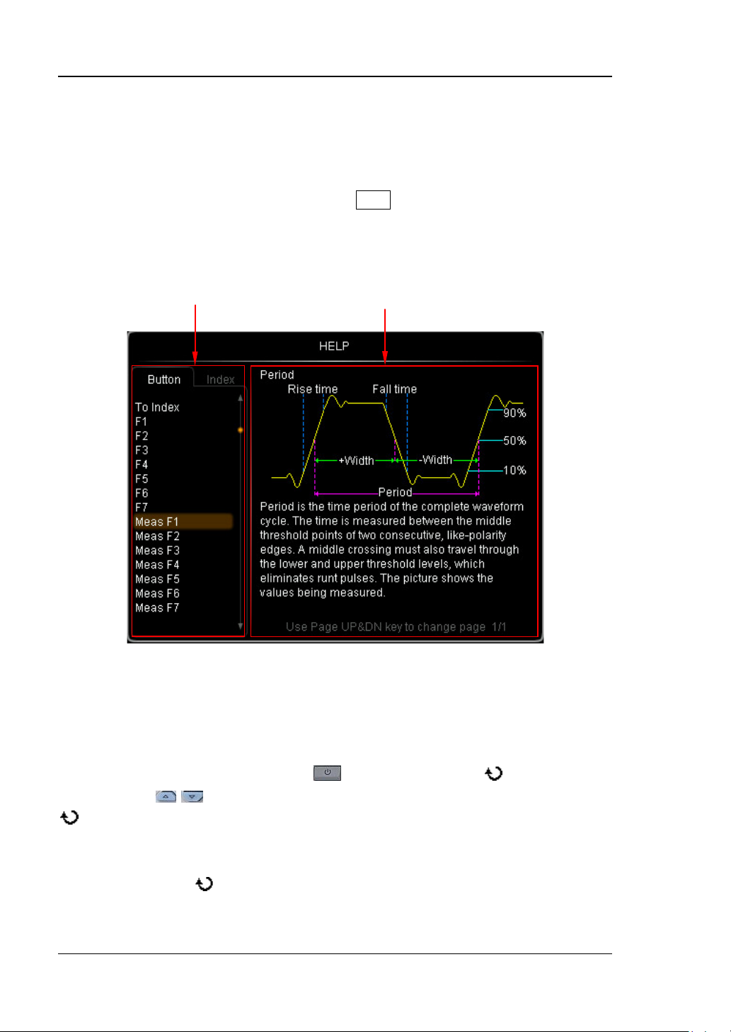
RIGOL Chapter 1 Quick Start
To Use the Built-in Help System
The help system of this oscilloscope provides instructions for all the function keys
and menu softkeys on the front panel. Press Help to open the help interface, and
press it again to close the inte rfa ce . The help interface consists of two sections. The
left section is "Help Options", and you can select the "Button" or "Index" tab. The
right section is "Help Display Area", which displays the help information.
Help Options Help Display Area
Figure 1-16 Help Information
Button:
By default, the "Button" tab is selected. Under the tab, you can vi ew the
corresponding help information in the "Help Display Area" by pressing the keys or
menu softkeys (except the Power key
Up/Down key
to select the desired key name (the item currently selected is displayed with
brown shading) in the “Help Options” area and then pressing down the knob.
Besides, you can acquire the help inf ormat ion of the na vigation kn ob b y rotati ng the
multi-function k nob
knob to quickly select "WaveSearch". To switch to the "Index" tab, use the
1-28 DS4000E User’s Guide
/ ) on the front panel directly or rotat ing the multi-fun ction knob
to select "WaveSearch" or directly rotating the navigation
, multi-function knob , and the Page
Page 53
Chapter 1 Quick Start RIGOL
multi-function k nob to select "To Index" and then press down the knob.
Index:
Under the tab, you can vie w the c orrespon ding help i nfor mation i n the "Help Displa y
Area" by rotating the multi-function knob
to sel ect the de sired key name (the
item currently selected is displayed with brown shading) in the “Help Options” area
and then pressing down the knob. To switch to t he Button tab, use the
multi-function k nob
to select "To Button" and then press down the knob.
DS4000E User’s Guide 1-29
Page 54

Page 55

Chapter 2 Vertical System Setting RIGOL
Chapter 2 Vertical System Setting
DS4000E provides four input channels (CH1 to CH4) and provides independent
vertical control system for each channel. As the vertical system setting methods of
the four channels are complete ly the same, this cha pter takes CH1 as an example to
illustrate the setting method of the vertical system.
The contents of this chapter:
To Turn the Channel On/Off
To Adjust the Vertical Scale
To Adjust the Vertical Position
To Specify the Channel Coupling
To Specify the Bandwidth Limit
To Set the Probe
To Specify the In pu t Impedance
To Turn Waveform Invert On/Off
To Specify the Vertical Reference
To Specify the Amplitude Unit
To Set the Channel Label
To Set the Delay Calibration
DS4000E User’s Guide 2-1
Page 56
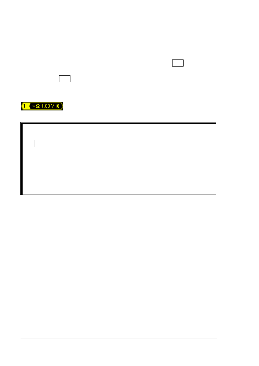
RIGOL Chapter 2 Vertical System Setting
To Turn the Channel On/Off
Connect a signal to the ch annel connect or of CH 1 and the n p ress CH1 in the vertical
control area (VER TICAL) a t the f ront panel to turn CH1 on or of f . When it is turned on,
the backlight of CH1 is illuminated; the channel setting menu is displayed at the
right of the screen and the channel status label ( as shown in the figure below) at the
bottom of the screen is highlighted.
Tips
The on/off of the backlights of the characters (“AC”, “50” and “BW”) under
CH1 and the information displayed in the channel status label are related to
the current channel setting. For the details, refer to “To Specify the
Channel Coupling”, “To Specify the Input Impedance” and “To
Specify the Bandwidth Limit”.
The on/off of the backlights of the characters (“AC”, “50” and “BW”) is only
related to the current channel set ting; the on/of f st ate of the chan nel has not
any effect on it.
After the channel is turned on, modify the parameters such as the vertical scale,
horizontal time base and trigger mode according to the input signal to make the
waveform d i splayed easy to observe and measure.
2-2 DS4000E User’s Guide
Page 57
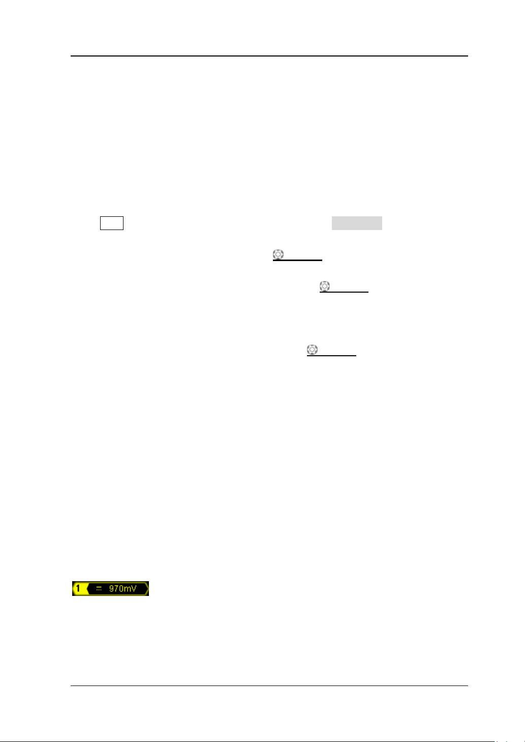
Chapter 2 Vertical System Setting RIGOL
To Adjust the Vertical Scale
The vertical scale refe rs to t he voltage value per grid on the vertical direction on the
screen and is usually e xpressed as V/div. The adjustable range of the vertical scale is
related to the current pr obe ratio an d in put i mpedance. By default, the probe r atio is
1X, the input impedance is 1 MΩ and the adjustable range of the vertical scale is from
1 mV/div to 5 V/div.
Press CH1 and its backlight is illuminated; then, press Volts/Div to switch the
vertical scale adjustment mode of CH1 between “Coarse” and “Fine” (the default is
“Coarse”). You can also press VERTICAL
quickly switch the current adjustment mode.
When “Coarse” is selected, turning VERTICAL SCALE will adjust the
vertical scale within the adjusta ble range at 1-2-5 step sequence. Turn the knob
clockwise to reduce the vertical scale and counterclockwise to increase the
vertical scale.
When “Fine” is s elected, turning VERTICAL SCALE will further adjust the
vertical scale within the adjustable range at a smaller step to improve the
vertical resolution. Turn the knob clockwise to reduce the vertical scale and
counterclockwise to increase the vertical scale.
SCALE corresponding to CH1 to
If the amplitude of the input wavef orm is a li tt le bit g reater tha n the full scale of
the current scale and the amplitude w ould be a little bit lower if the next s cale is
used, fine adjustment can be used to improve the waveform display amplitude
to view signal details.
When modifying the vertical scale, the waveform of the correspondi ng channe l will
be expanded or compressed vertically relative to the vertical reference currently
selected (refer to “To Specify the Verti cal Reference”); the vertical scale
information (as shown in the figure below) in the channel status label at the bottom
of the screen will change in real ti me.
DS4000E User’s Guide 2-3
Page 58
RIGOL Chapter 2 Vertical System Setting
To Adjust the Vertical Position
The vertical position refers to the position of the ground level of the waveform
relative to the screen center in the vertical direction. The adjustable range of the
vertical position is related to the current input impedance, probe ratio and vertical
scale (refer to "Specifications"). The unit is the same as the amplitude unit
currently selected (refer to "To Specify the Amplitude Unit").
Press CH1 and its backlight is illuminated; then, turn VERTICAL
corresponding to CH1 to adjust the vertical position of the channel waveform within
the adjustable range.
T urn the k nob clockwise to increase the vertical p osition and counterclockwise t o
reduce the vertical position.
Press this knob to quickly reset the vertical position to 0.
When modifying the vertical position, the waveform of the corresponding channel
moves up and down; the vertical position inf ormation (as shown in the figure below)
pops up at the lower -left side of the screen in real-time.
POSITION
2-4 DS4000E User’s Guide
Page 59
Chapter 2 Vertical System Setting RIGOL
To Specify the Channel Coupling
Set the coupling mode to filter out the undesired signals. For example, the signal
under test is a square waveform with DC offset.
When the coupling mode is “DC”, the DC and AC c omponents of the signal und er
test can both pass the channel.
When the coupling mode is “AC”, the DC c omponents of the sig nal under test a re
blocked.
When the coupling mode is “GND”, the DC and AC components of the signal
under test are both blocked.
Press CH1 Coupling and turn the multi-function knob to select the desired
coupling mode (the default is DC). You can also press Coupling continuously to
switch the current coupling mode. When different coupling mode is selected,
different coupling label is displayed in the channel status label at the bottom of the
screen, as shown in the figure below. When “AC” coupling mode is selected, the
character “AC” below CH1 is illuminated.
DC AC GND
DS4000E User’s Guide 2-5
Page 60
RIGOL Chapter 2 Vertical System Setting
To Specify the Bandwidth Limit
Setting the bandwidth limit can reduce display noise. For example, the signal under
test is a pulse with high-frequency oscillations.
When bandwidth limit is disabled, the high frequency components of the signal
under test can pass the channel.
Enable bandwidth limit and limit the bandwidth to 20 MHz or 100 MH z
high-frequency components of the signal under test that exceed 20 MHz or 100
MHz are attenuated.
Press CH1 BW Limit and turn the multi-function knob to select the desired
bandwidth limit state (the default is OFF). You can also press BW Limit continuously
to switch the current state of bandwidth limit. When the bandwidth limit (20 MHz or
100 MHz) is enabled, the label as shown in the figure below is displayed in the
channel status label at the bottom of t he screen and the character “BW” under CH1
is illuminated.
[1]
; the
[1]
Note
MHz bandwidth limit.
: DS4024E support 20 MHz and 100 MHz bandwidth limits and DS4014E only support 20
To Set the Probe
The channels of this oscilloscope support normal passive probes, active probes and
Tek probes (with RIGOL T2R1000 active probe adaptor, option). The oscilloscope
can automatically identify the type of the probe currently connected and the probe
ratio. For the detailed technical information of the probes, please refer to the
correspondin g probe Use r’s Guide. Press CH1 Probe to open the probe submenu.
You can view different information and perform different operations in the submenu
when different typ e of probe is co nnected.
2-6 DS4000E User’s Guide
Page 61
Chapter 2 Vertical System Setting RIGOL
Attenuation Coefficient
0.01X
0.01:1
Passive Probe
1. Probe Type
Probe Type displays “Nor-Probe”; for example, when RIGOL RP3300A probe is
connected.
2. Ratio
For so me normal passive probes, the oscilloscope can identify the probe ratio
automatically. If not, press Ratio and turn the multi-function knob to select
the corresponding probe r atio; or press Ratio contin uously t o switch t he curre nt
probe ratio. The probe ratios available are listed in
Table 2-1 Probe Attenuation Coefficient
Table 2-1.
Probe Ratio
0.02X
0.05X
0.1X
0.2X
0.5X
1X
2X
5X
10X
20 X
50 X
100 X
200 X
500 X
1000 X
(waveform display amplitude : actual waveform amplitude)
0.02:1
0.05:1
0.1:1
0.2:1
0.5:1
1:1
2:1
5:1
10:1
20:1
50:1
100:1
200:1
500:1
1000:1
3. Bias Voltage
The oscilloscope provides the bias voltage adjustment function for normal
probes. This function is used to adjust the signal under test that exceeds the
measurement range of the probe to an appropriate range to e nsure the integ rity
of the signal under test. Press Bias Voltage and turn the multi-function knob
to adjust the DC bias voltage. The range is from -4*Vertical Scal e+Vertical
Position to 4*Vertical Scale+Vertical Position.
DS4000E User’s Guide 2-7
Page 62
RIGOL Chapter 2 Vertical System Setting
Active Probe
1. Probe Type
Probe Type displays “ Active Probe”; for example, when RIGOL RP7150 probe
is connected.
Note: When a 50 Ω active probe is connected, the input impedance of the
channel (refer to “To Specify the Input Impedance”) will be set to “50 Ω”
automatically.
2. Ratio
For active probes, the oscilloscope can identify the p robe ratio automatically. If
the probe currently connected supports multiple probe ratios, press Ratio and
turn the multi-function knob
Ratio continuously to switch the current probe ratio.
3. Front-End
Press Front-End to select the probe front end that matches the probe actually
connected. You can select single-end or differential.
4. Probe-Cal
The oscilloscope provides the calibration function for active probes. This
function uses the fast edge signal output from the [Trig Out/Ca li bration]
connector at the rear panel of the instrument as the probe calibration signal.
Before perfo rm ing probe ca li bration, pre s s Utility AuxOutput and select
“Fast” to configure the [Trig Out/Calibration] connector at the rear panel of
the instrument to output fast edge signal.
The following part introduces how to calibrate the probe via the oscilloscope
(take CH1 as an example) using PCK100 active differential probe calibration kit
by taking RP7150 as a n ex ample. F or the detaile d calibration procedures, please
refer to
RP7000 Series Active Probe User’s Guide
1) Connect RP7150 to CH1 input terminal of the oscilloscope correctly.
2) Press CH1 Probe Probe-Cal to open the probe calibr ation menu. At
this time, the probe calibrati on prompt message is displayed.
3) Connect the calibration board to CH2 input terminal of the oscilloscope and
the [Trig Out/Calibration] connect or at the rear panel res pectively using
to select the desired probe ratio; or pre s s
.
2-8 DS4000E User’s Guide
Page 63
Chapter 2 Vertical System Setting RIGOL
connectors according to the probe calibrati on pro m pt mess age .
4) Adjus t the di stance between the RP7150 probe tips. Connect the positive
probe tip to the signal at the moddile of the calibration board and connect
the negative probe tip to both sides of the signal line.
5) Press OK and the oscilloscope starts to calibrate the probe.
Note: Please connect the probe calibration signal to the specified channel
according to the probe calibration prompt message. If the active probe is
connected to CH1, CH3 or CH4, the probe calibration signal should be connected
to CH2 via the clibration board. If the active probe is connected to CH2, the
probe calibration signal should be connected to CH1 via the calibration board.
5. Probe Info
Press Probe Info to view information about the probe currently connected,
such as the manufacturer, model, serial number and the date of last calibration.
6. Bias Voltage
The oscilloscope provides the bias voltage adjustment fun ction for active probes.
This function is used to adjust the signal under test that exceeds the input
dynamic range of the probe amplifier to an appropriate range to ensure the
integrity of the signal under test. Press Bias Voltage and turn the
multi-function k nob
to adjust the DC bias voltage. The range is from -12 V
to +12 V.
Tek Probe
1. Pro be Type
Probe Type displays “Tek Probe”; for example, when Tek (Tektronix) P6245
probe is connected.
Note: When a Tek probe is used, the oscilloscope sets the channel input
impedance automatically according to the model of the probe actually
connected.
2. Mode
Press Mode and turn the multi-function knob to select the probe model
corresponding to the probe actually connected. You can press this softkey
DS4000E User’s Guide 2-9
Page 64

RIGOL Chapter 2 Vertical System Setting
continuously to switch the current probe model. The probe models available
include P6205, P6241, P6243, P6245, P6246, P6247, P6248, P6249, P6250,
P6251, P5205, P5210, P670X, P671X and TCP202.
3. Ratio
Ratio displays the current probe ratio. If the probe currently connected
supports multiple probe ratios, you can use Ratio to select the desi red probe
ratio. The probe ratios available are related to the model of the probe.
4. Front-End
Front-End displays the type of the front end of the probe currently c onnected.
If the probe currently connected is P670X, P671X or TCP202, this menu item is
not provided.
In addition, the oscilloscope supports the probe calibration and bias voltage
adjustment of some Tek probes, including P6241, P6245, P6246, P6247, P6248,
P6249, P6250 and P6251. For these probes, Probe-Cal and Bias Voltage are
provided in the probe submenu .
5. Probe-Cal
Press Probe-Cal and ground the probe input terminal according to the probe
calibration prompt message. Press OK and the oscilloscope sta rts calibratin g the
probe.
6. Bias Voltage
Press Bias Voltage and turn the multi-fu nction knob to adjust the DC bias
voltage.
Note: The adjustable range of the DC bias voltage is related to the probe model
and probe ratio (only for models that suppo rts multiple probe ratios). Fo r the
details, please refer to the technical specifications of the corresponding probe.
2-10 DS4000E User’s Guide
Page 65
Chapter 2 Vertical System Setting RIGOL
To Specify the Input Impedance
To reduce the circuit load caused by the interaction between the oscillos cope and the
circuit under test, the oscilloscope provides two input impedance modes: 1 MΩ
(default) and 50 Ω.
1 MΩ: at this point, the input im pedance of the oscilloscope is v ery high an d the
current flows into the oscilloscope from the circuit under test can be ignored.
50 Ω: match the oscilloscope with devices with 50 Ω output impedance.
Press CH1 and its backlight is illuminated; then, press Input to switch the input
impedance o f the oscilloscope. When “50 Ω” is selected, the label as shown in the
figure below is displayed in the channel status label at the bottom of the screen; at
the same time, the character “50” under CH1 is illuminated.
Note:
After automatically identifying the probe , the oscilloscope indentifies the input
impedance automatically and you do not need to set the input impedance
manually.
The input impedance setting will affect the settable ranges of the vertical scale
and vertical offset of the channel. Please refer to “Specifications”.
DS4000E User’s Guide 2-11
Page 66
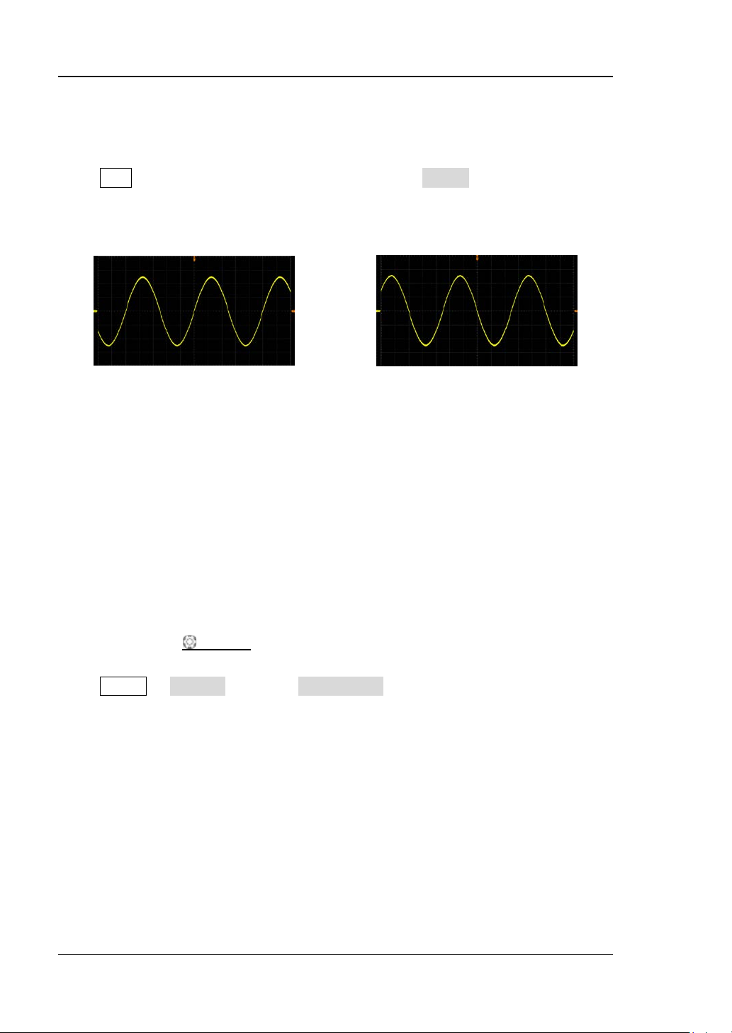
RIGOL Chapter 2 Vertical System Setting
To Turn Waveform Invert On/Off
Press CH1 and its backlight is illuminated; then, press Invert to turn on or off
waveform invert (the default is off). When waveform invert is tu rn e d off, the
waveform display is normal; when waveform invert is turned on, the wavefor m
voltage values are inverted (as shown in the figures below).
(a) “Invert” is Off
Figure 2-1 Waveform Invert
Note: Turning waveform invert on will change the results of math operations and
waveform measurements.
(b) “Inv ert” is On
To Specify the Vertical Reference
The vertical reference refers to the reference position according to which the
waveform of the corresponding channel is expanded or compressed vertically when
using VERTICAL
Press Utility System and press VerticalExp to switch the current vertical
reference (the default is Ground).
Center: when the vertical scale is modified, the waveform of the corresponding
channel will be expanded or compressed relative to the center of the screen.
Ground: when the vertical s cale is m odified, the waveform of the corresponding
channel will be expanded or compressed relative to the ground level.
SCALE to modify the vertical scale of the analog channel.
2-12 DS4000E User’s Guide
Page 67
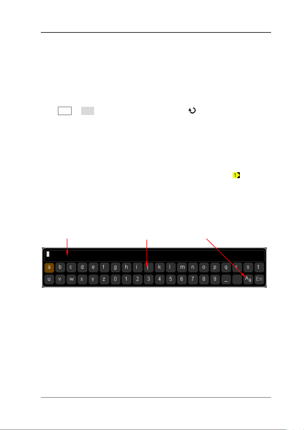
Chapter 2 Vertical System Setting RIGOL
To Specify the Amplitude Unit
Select the amplitude displa y unit for the current c hannel. The available units are “W”,
“A”, “V” and “U”. When the unit is changed, the amplitude unit displayed in the
channel status label will change accordingly.
Press CH1 Unit and turn the multi-function knob to select the desired
amplitude unit (the default is V).
To Set the Channel Label
By default, the oscilloscope uses the number of the channel (such as
at the left of the screen) to mark the corresponding analog channel. For easier use,
you can define a label for each analog channel.
The label modification interface is as shown in the figure below.
Name Input Area Keyboard Upper/Lower Case Switch
, displaye d
Name Input Area: display the label characters currently input;
Keyboard: used to input the specified character;
Upper/Lower Case Switch: used to switch between English uppercase and
lowercase inputs. “
Note: The user-defined label can include uppercase English letters (from A to Z),
lowercase English letters (from a to z), numbers (from 0 to 9), underline and space;
the length of the label cannot exceed 4 characters.
DS4000E User’s Guide 2-13
A
a” denotes lowercase and “aA” denotes uppercase.
Page 68
RIGOL Chapter 2 Vertical System Setting
For example, change the label of CH1 to “Chn1”.
1. Press CH1 Label to open the lable submenu and the label modification
interface (as shown in the figure above).
If there are characters in the “Name Input Area”, please press Delete
continuously to delete all the characters.
2. Input the first character “C”.
1) If the system is in uppercase input (“
2)
. If the system is in lowercase input (“Aa” is displayed), please press
a
A” is displayed), please move to step
Keyboard to select the “Keyboard” area, turn the multi-function knob
to select “
A
a” and press the knob to switch to “aA”.
2) Press Keyboard to select the “Keyboard” area, turn the multi-function
knob
to select “C” and press the knob to input this character in the
“Name Input Are a ”.
3. U se the same method to input the remaining characters “hn1”. Pay attention to
the cases of the letters during the input process.
4. To modify the characters input, press Name to select the “Name Input Area”,
turn the multi-function knob
to select the character to be modified and then
input the desired character according to the operation method in step 2.
To delete the characters input, press Name to select the “Name Input Area”,
turn the multi-function knob
to select the character to be deleted and then
delete this character by pressing Delete.
Note: When the “Keyboard” area is currently selected, you can also press
Delete to delete the character currently at the cursor or the first chara cter at
the left of the cursor (if there is no character at the cursor).
5. Af ter finishing the input, press OK to complete the label modification. The
channel label will change to
.
2-14 DS4000E User’s Guide
Page 69
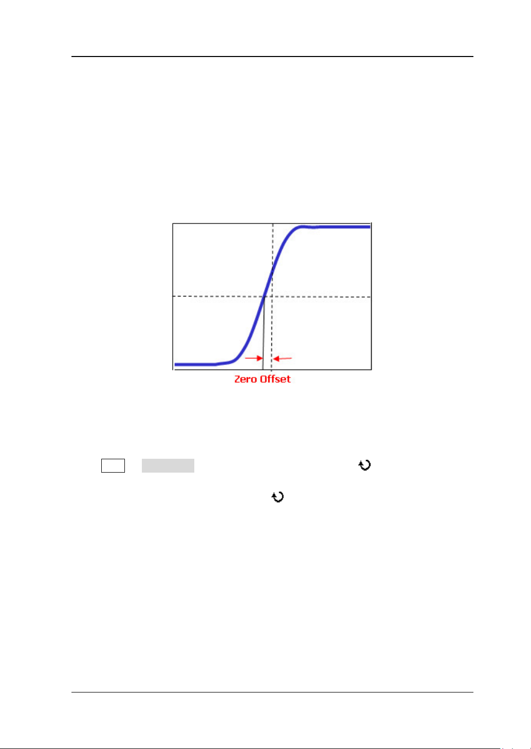
Chapter 2 Vertical System Setting RIGOL
To Set the Delay Calibration
When using an oscilloscope for actual measur ements, the transmission delay of the
probe cable may bring gre at er er r or (ze ro of f se t). Zero offset is defined as the offset
of the crossing point of the waveform an d trigger level line relative to the actual
trigger position, as shown in the figure below.
Actual Trigger Position
Trigger Level
DS4000E allows users to set a delay time to calibrate the zero offset of the
corresponding channel.
Press CH1 Delay-Cal and turn the multi-function knob to adjust the delay
time (the default is 0.00 s) at certain step. The adjustable range is from -100 ns to
100 ns. Pressing the multi-function knob
can quickly reset the delay time to
0.00 s.
Note: The delay calibration time setting is related to the instrument model and the
current horizontal time base. The larger the horizontal time base is, the larger the
setting step will be. Take DS4024E as an example; when the horizontal time base is
50 ns, the step is 1 ns; when the horizontal ti me base is 2 μs, the step is 40 ns; when
the horizontal time base is greater than or equal to 10 μs, the delay calibration time
cannot be adjus t ed.
DS4000E User’s Guide 2-15
Page 70

Page 71

Chapter 3 Horizontal System Setting RIGOL
Chapter 3 Horizontal System Setting
The contents of this chapter:
To Adjust the Horizontal Time Base
To Adjust the Horizontal Position
To Specify the Time Base Mode
To Turn Delayed Sweep On/Off
To Specify the Horizontal Reference
DS4000E User’s Guide 3-1
Page 72
RIGOL Chapter 3 Horizontal System Setting
To Adjust the Horizontal Time Base
The horizontal time base (also called horizontal scale) refers to the time value per
grid in the horizontal direction on the screen and is usually expressed as s/div. The
adjustable range of the horizontal time base is related to the instrument model, as
shown in the table below.
Table 3-1 Horizontal Time Base Range
Model Horizontal Time Base Range
DS4024E 2.000 ns/div to 1.000 ks/div
DS4014E 5.000 ns/div to 1.000 ks/div
Press MENU in the horizontal control area (HORIZONTAL) at the front panel and
press ScaleAdjust to switch the horizont al time base adjustment mode to "Coarse"
or "Fine" (the default is coarse).
When “Coarse” is selected, turning HORIZONTAL SCALE will adjust the
horizontal time base within the adjustable range at 1-2-5 step sequenc e. Turn
the knob clockwise to reduce the horizontal time base and counterclockwise to
increase the horizontal time base.
When “Fine” is selected, turning HORIZONTAL SCALE will further adjust
the horizontal time base within the adjustable range at a smaller step. Turn the
knob clockwise to reduce the horizontal time base and counterclockwise to
increase the horizontal time base.
When modifying the horizontal time base, the waveform displayed will be expanded
or compressed horizontally relative to the horizontal reference currently selected
(refer to “To Specify the Horizontal Reference”); the time base information (as
shown in the figure below) at the upper-left side of the screen will change
accordingly.
Note: When delayed sweep is turned on, HORIZONTAL
adjust the delayed sweep time base; the delayed sweep time base information (as
shown in the figure below) at the middle of the screen changes accordingly.
3-2 DS4000E User’s Guide
SCALE is used to
Page 73
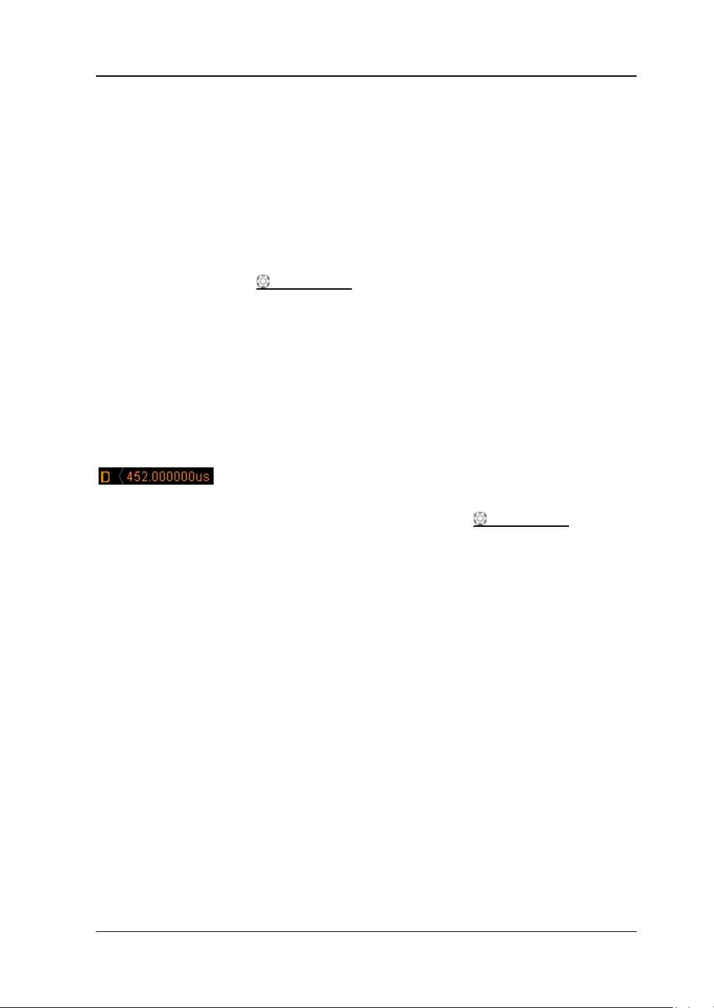
Chapter 3 Horizontal System Setting RIGOL
To Adjust the Horizontal Position
The horizontal position (also called trigger posi t ion) refers to the position of th e
trigger point of the wa veform relative t o the screen cent er in t he hori zontal dire ction.
The horizontal position is positive (negative) when the waveform trigger point is at
the left (right) of the screen center.
Turning HORIZONTAL
channel waveform.
Turn the knob clockwise to reduce the horizontal position and counter cl ockwise
to increase the horizontal position.
Pressing the knob can quickly reset the horizontal position to 0.
When modifying the horizontal position, the trigger point and the waveforms
displayed move left or right; the horizontal position information (as shown in the
figure below) at the upper-right side of the screen changes accordingly.
POSITION can adjust the horizontal position of the
Note: When delayed sweep is turned on, HORIZONTAL
adjust the delayed sweep horizontal position (pressing this knob can quickly reset
the delayed sweep horizontal position); the delayed sweep horizontal position
information (as shown in the figure above) at the upper-right side of the screen
changes accordingly.
POSITION is used to
DS4000E User’s Guide 3-3
Page 74
RIGOL Chapter 3 Horizontal System Setting
To Specify the Time Base Mode
Press MENU in the horizontal control area (HORIZONTAL) at the front panel; then,
press Time Base, turn the multi-function knob to select the desired time base
mode and press the knob. Y ou can also press Time Bas e continuously to swit ch the
current time base mode. The modes available include Y-T, X-Y and Roll and the
default is Y-T.
Y-T Mode
In this mode, the Y axis represents voltage and the X axis represents time.
Note: Only in this mode can delayed sweep be turned on (refer to “To Turn
Delayed Sweep On/Off”).
Slow Sweep Mode
In “Y-T” time base mode, when the horizontal time base is greater than or equal to
200 ms/div, the instrument enters “Slow Sweep” mode. In “Slow Sweep” mode, the
oscilloscope first samples the data at the left of the trigger point; then, it waits for
trigger and finishes the waveform at the right of the trigger point. When the slow
sweep mode is used to observe low-frequency signal, it is recommended that the
“channel coupling” is set to “DC” (refer to “To Specify the Channel Coupling”).
Note: Please pay attention to distinguish the slow seep mode from “Roll Mode”.
X-Y Mode
In this mode, the X axis and Y axis both represents voltage. The oscilloscope
automatically turns on all the four channels (CH1 to CH4) a nd the screen is divided
into two areas (XY1 and XY2). In XY1 area (at the left of the screen), the X axis and
Y axis track the voltages of CH1 and CH2 respectively ; in XY2 area (at the right of the
screen), the X axis and Y axis track the voltages of CH3 and CH4 respectively.
The X-Y time base mode can be used to test the phase variation of a signal when it
3-4 DS4000E User’s Guide
Page 75
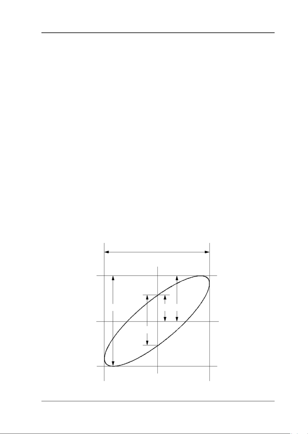
Chapter 3 Horizontal System Setting RIGOL
passes through a circuit network. Connect the oscilloscope with the circuit and
monitor the input and output signals of the circuit.
Note:
In this mode, the “To Adjust the Horizontal Position”, “To Turn Delayed
Sweep On/Off”, “To Specify the Acquisition Mode”, “Trigger”, “To Make
Math Operation”, “To Make One-key Measurement”, “To Specify the
Measurement Range”, “Protocol Decoding”, “Reference Waveform”,
“Pass/Fail Test”, “Waveform Recording” and “Vectors” are not available.
The “X-Y” cursor mode (refer to “X-Y Mode”) is only av ail able in this time base
mode.
If delayed sweep is currently turned on, when the “X-Y” mode is turned on, the
delayed sweep will be turned off automatically. When the “Y-T” mode is turned
on again, the delayed sweep will be turned on automatically.
Phase Deviation Measurement Principle
The phase deviation between two signals with the same frequency can be easily
measured via the Lissajous method. The figure below shows the measurement
principle of the phase deviation (assume that the amplitudes of the two signals are
the same).
The signal must be horizontally centered
II I
D
C
A
III IV
B
DS4000E User’s Guide 3-5
Page 76
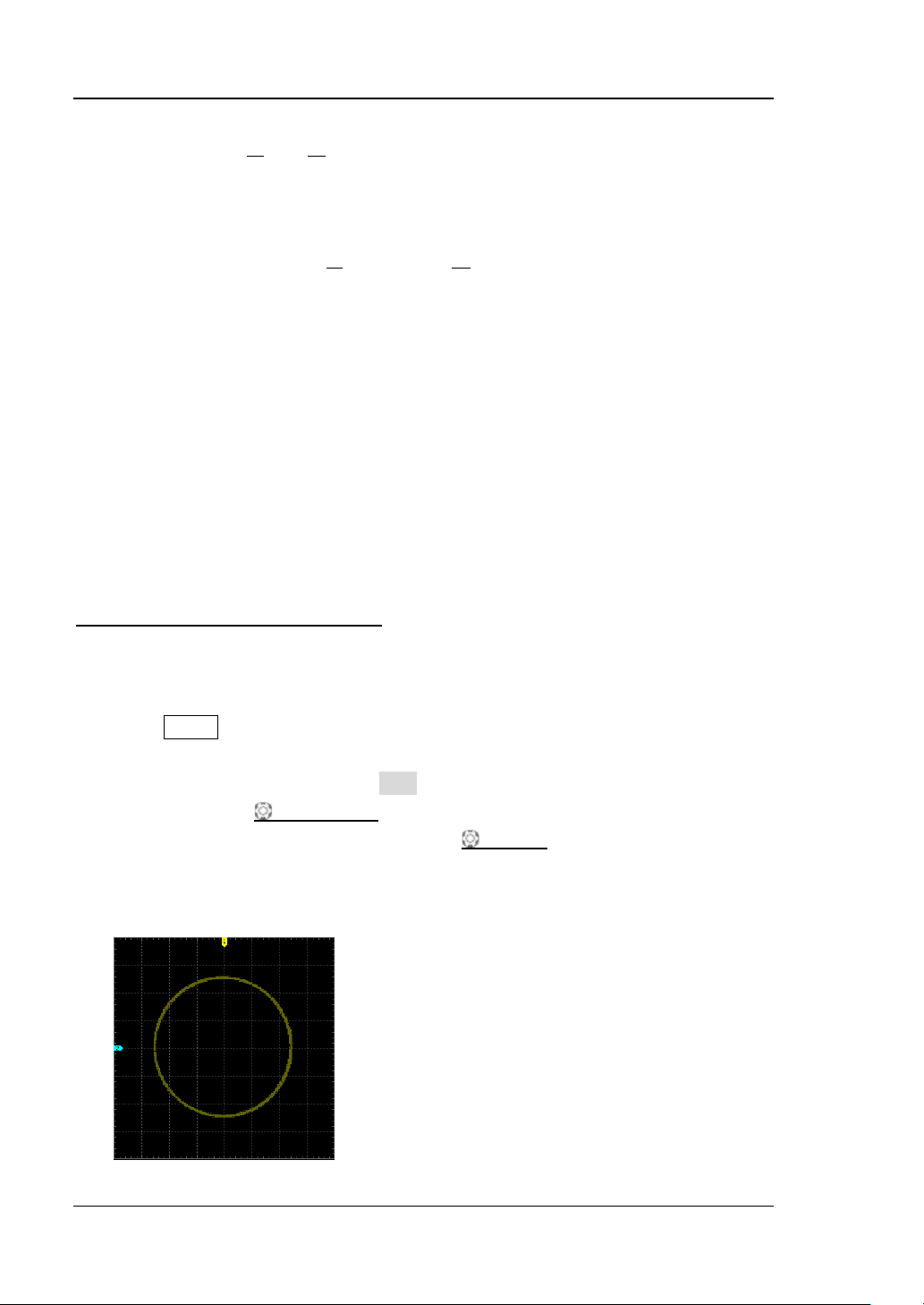
RIGOL Chapter 3 Horizontal System Setting
B
A
sin =θ
D
C
A, B
B
A
arcsin±=θ
D
C
arcsin±
According to
channels; the definitions of
you can calculate the phase deviation angle.
If the principal axis of the ellipse is within quadrant I and III, the phase deviation
angle obtained should be within quadrant I and IV, namely wit hin (0 to π/2) or (3π/2
to 2π). If the principal axis of the ellipse is within quadrant II and IV, the phase
deviation angle obtained s hould be within quadrant II and III, namely within (π/2 to
π) or (π to 3π/2).
or
(wherein, θ is the phase deviation angle between the
, C and D are as shown in the figure above),
or
Application example: measure the phase deviation of the input
signals of two channels.
Method 1: Use Lissajous method
1. Co nnect a sine signal to CH1 and then connect a sine signal with the same
frequency and amplitude but a 90° phase deviation to CH2.
2. Press AUTO and turn on the X-Y time base mode.
If the XY1 area displ ay i s turned on, please move to the next step. If the XY1
area display is tu rn e d o ff, press XY1 to switch to “On”.
3. Use VERTICAL POSITION of CH1 and CH2 to display the signals at the
center of the screen and use VERTICAL
the signals easy to observe (if necessary, please refer to “
Vertical Sca le” to switch the vertical s cale adjustment mode). At this point, the
circle as shown in the figure below should be displayed.
SCALE of CH1 and CH2 to make
To Adjust the
3-6 DS4000E User’s Guide
Page 77

Chapter 3 Horizontal System Setting RIGOL
1=
)(
D
C
B
A
°90±=1±=θ arcsin
4. According to the phase deviation measurement principle diagram and the
measurement result in the fig ure above, it can be calculated that
Therefore, the phase deviation angle
Note: The maximu m s ample rate of the oscilloscope in the X-Y mode is 2 .0 GSa/s.
Generally, longer sample waveform ensures better figure; but, as being limited by
the memory depth, longer waveform will require a reduction in the sample rate
(please refer to “To Set the Memory Depth
process, reducing the sample rate appropriately can improve the displa yed Lissajous
figure.
Method 2: Use the one-key measurement function of the oscilloscope
Please measure the phase deviation between the input waveforms of CH1 and CH2
using the one-key measurement function by referring to “To Make One-key
Measurement”.
”). Therefore, in this measurement
.
.
Roll Mode
In this mode, the waveform scrolls from the right t o the left. The adjustable range of
the horizontal time base is from 200.0 ms/div to 1.000 ks/div. The horizontal time
base will be set to 200.0 ms/div automatically when you turn on the “Roll” mode.
In this mode, the “To Adjust the Horizontal Position”, “To Turn Delayed
Sweep On/Off”, “Trigger”, “To Specify the Measurement Range”, “Protocol
Decoding”, “Pass/Fail Test”, “Waveform Recording” and “To Set the
Persistence Time” are not available.
If the delayed sweep function is enabled, when the “Roll” mode is enabled, the
delayed sweep function will be disabled automatically; when the “Y-T” mode is
enabled again, the delayed sweep function will be enabled automatically.
Note: Please pay attention to distin guish the Roll mode from “Slow Sweep Mode”.
DS4000E User’s Guide 3-7
Page 78
RIGOL Chapter 3 Horizontal System Setting
To Turn Delayed Sweep On/Off
Delayed sweep can be used to enlarge a length of w a vef orm h orizontally t o vie w the
waveform details.
Note: Delayed sweep can only be turned on when the current time base mode is
“Y-T” and the “Pass/Fail” test is off.
Press MENU in the horizontal control area (HORIZONTAL) and press Delayed to
turn delayed sweep (the default is off) on or off. You can also p re s s HORIZONTAL
SCALE to quickly switch the on/off status of the delayed sweep.
When delayed sweep is turned on, the screen is divided into two display areas as
shown in the figure below. The wavef o rm of n or mal s wee p is displayed in the uppe r
part of the screen and its horizontal ti me base (calle d main time base) is displayed at
the upper-left side of the screen. The delayed sweep waveform (the horizontally
expanded waveform) is displayed in the lower part of the screen, its horizontal time
base (called delayed sweep time base) is displayed at the middle of the screen and
its horizontal position (called delayed sweep horizontal position) is displayed at the
upper-right side of the screen. At this point, HORIZONTAL
adjust the delayed sweep time base; HORIZONTAL
adjust the delayed sweep horizontal position.
POSITION is used to
SCALE is used to
3-8 DS4000E User’s Guide
Page 79
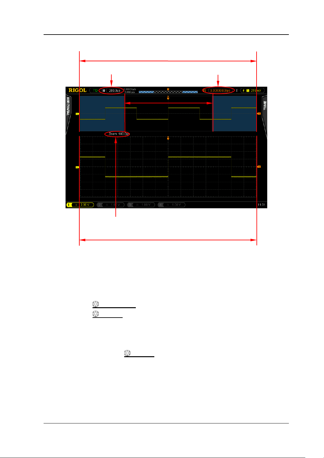
Chapter 3 Horizontal System Setting RIGOL
Main Time Base
Normal Sweep Waveform
Delayed Sweep Horizontal Position
Waveform before enlargement
Delayed Sweep Time Base
Delayed Sweep Waveform (waveform after enlargement)
Waveform before enlargement:
The waveform of normal sweep is displayed in the upper part of the screen. Wherein,
the waveform in the area (called the enlargement area) that has not been cove red by
subtransparent blue is the waveform before enlargement (correspond to the
wavef orm afte r enlargement display ed i n the lowe r part of the screen). You can turn
HORIZONTAL
HORIZONTAL
POSITION to move the enlargement area left or right or turn
SCALE to enlarge or reduce the enlargement area.
Note: To modify the horizontal time base of normal sweep (namely, the main time
base), delayed sw e ep should be turned off. After setting the desired main time base
by turning HORIZONTAL
SCALE, turn on delay ed sweep.
Waveform after enlargement:
The delayed sweep waveform in the lower part of the screen is the enlarged
waveform (the horizontally expanded wavefo rm). It corresponds to the waveform
before enlargement in the upper part of the screen. Compa red to the ma in ti me base ,
DS4000E User’s Guide 3-9
Page 80
RIGOL Chapter 3 Horizontal System Setting
the delayed sweep time base improves the waveform resolution (as shown in the
figure above).
Note: The de layed sweep time base should be less than or equal to the main time
base.
To Specify the Horizontal Reference
The horizontal reference is the reference position according to which the screen
waveform is expanded or compressed horizontally when using HORIZONTAL
SCALE to modify the horizontal time base.
Note: Y ou ca n only set th e horizontal reference whe n the “Y-T” mode is used and the
delayed sweep is on.
Press MENU (in the horizontal control area (HORIZONTAL)) HorRef, turn the
multi-function knob to select the desired horizontal reference position and press
the knob to select this pos i tion (the default is the screen center). You can also press
HorRef continuously to switch the current horizontal reference position.
Center: when changing the horizontal time base, the waveform displayed is
expanded or compressed horizontally relative to the center of the screen.
Trigger Pos: when changing the horizontal time base, the wa veform is expanded
or compressed horizontally relative to the trigger poi n t.
User: when changing the horizontal time base, the waveform is expanded or
compressed horizontally relative to the user-defined reference position.
When “User” is selected, press RefPos and turn the multi-function knob to
set the user-defined reference position. The adjustable range is from -350 (the
rightmost) to 350 (the leftmost). The default is 0 (screen center). Pressing the
multi-function k nob
can quickly reset the reference position to 0.
3-10 DS4000E User’s Guide
Page 81

Chapter 4 Sample System Setting RIGOL
Chapter 4 Sample System Setting
The contents of this chapter:
Sample Mode
Sample Rate
To Specify the Acquisition Mo de
To Set the Memory Depth
To Turn Anti-aliasing On/Off
DS4000E User’s Guide 4-1
Page 82
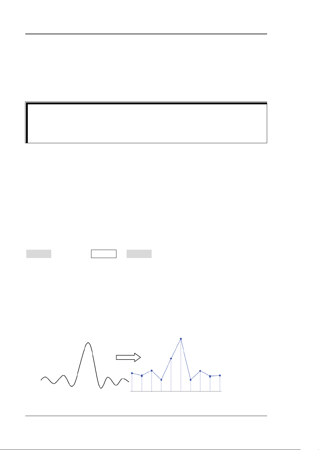
RIGOL Chapter 4 Sample System Setting
point, you can still use the vertical control and horizontal control to pan and zoom
Sample Mode
This oscilloscope only supports real-time sampling. In this mode, the oscilloscope
samples and displays waveforms within a trigger event.
Tip
When the sample is stopped, the oscilloscope will hold the last display. At this
the waveform.
Sample Rate
Sample refers to the process that the oscilloscope converts analog signals to digital
signals at a certain time interval and stores the data in order. The sample rate is the
reciprocal of the time interval.
The real-time sample rate of DS4000E is up t o 2 GSa/s for each channel. The current
sample rate is displayed in the status bar at the upper side of the screen and in the
Sa Rate menu (press Acquire Sa Rate). You can change the sample rat e
indirectly by modifying the horizontal time base (refer to “To Adjust the
Horizontal Time Base”) or memory depth (re fer to “To Set the Memory
Depth”).
The influence on the waveform when the sample rate is too low:
1. Waveform Distortion: when the s ample rate is too low, some waveform
details are lost and the waveform displayed is rather different from the actual
signal.
4-2 DS4000E User’s Guide
Page 83
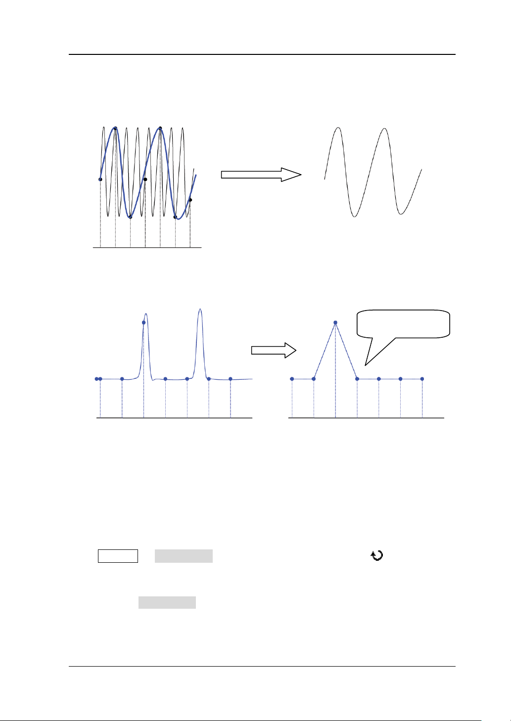
Chapter 4 Sample System Setting RIGOL
2. Waveform Confusion: when the sample rate is lower than twice the actual
signal frequency (Nyquist Frequency), the frequency of the waveform rebuilt
from the sample data is lower than the actual signal frequency.
3. Waveform Leakage: when the sample rate is too low, the waveform rebuilt
from the sample data does not reflect the actual signal completely.
Pulse disappeared
To Specify the Acquisition Mode
The acquisition mode is used to control how to generate waveform points from
sample points.
Press Acquire Acquisition and turn the multi-function knob to select the
desired acquisition mode; then, press the knob. The acquisiton modes available
include normal, aver age , peak dete ct and high-resolu tion. The default is nor mal. You
can also press Acquisition continuously to switch the current acquisition mode.
DS4000E User’s Guide 4-3
Page 84
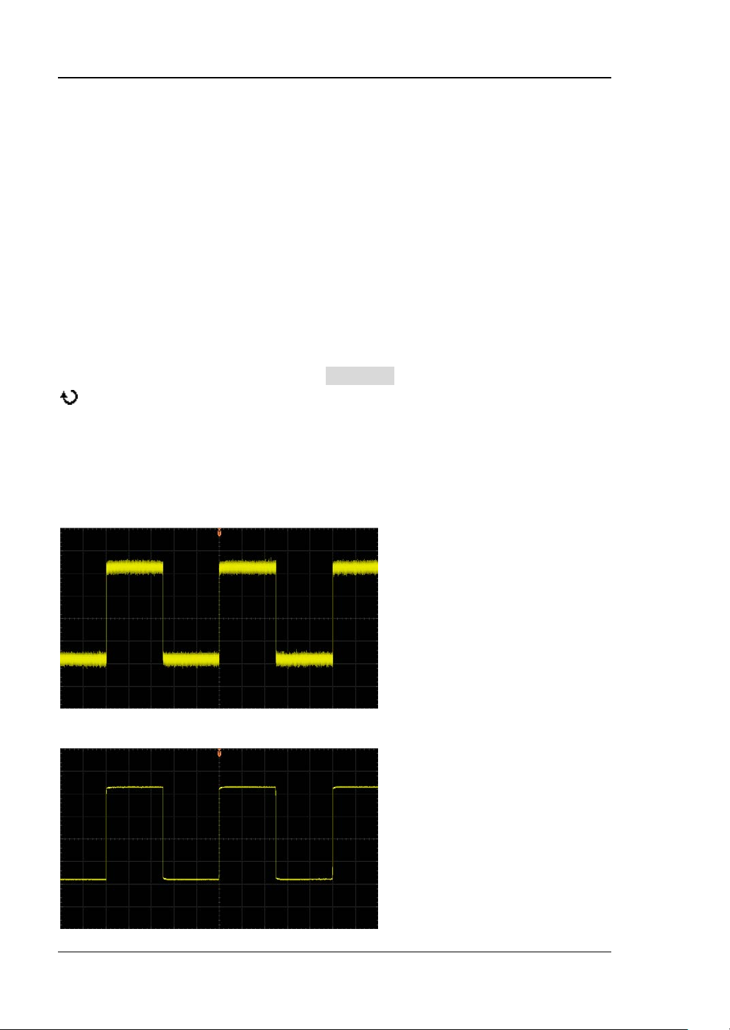
RIGOL Chapter 4 Sample System Setting
Normal
In this mode, the oscilloscope sam ples the signal at equal time inte rval to re build the
waveform. For most of the waveforms, the best display effect can be obtained using
this mode.
Average
In this mode, the oscilloscope averages the waveforms from multiple samples to
reduce the random noise of the input signal and improve the vertical resolution.
When “Average” mode is s elected, press Averages and turn the multi-function kno b
to increase or reduce the number of averages. The numbers of averages
available include 2, 4, 8, 16, 32, 64, 128, 256, 512, 1024, 2 048, 4096 a nd 8 19 2. Th e
default is 2. More averages can low er the noise and increase the vertical resolution;
but, it will slow the response of the displayed waveform to the waveform changes.
The waveform before average:
The waveform after 256 averages:
4-4 DS4000E User’s Guide
Page 85

Chapter 4 Sample System Setting RIGOL
Peak Detect
In this mode, the oscilloscope acquires the maximum and minimum values of the
signal within the sample in terval to get the envel ope of the signal or the narrow pulse
that might be lost. In this mode, signal confusion can be prevented but the noise
displayed would be larger.
In this mode, the oscilloscope can display all the pulses with pulse widths at le ast as
wide as the sample period.
High Resolution
This mode uses an over-sample technique to average the neighboring points of the
sample waveform. This reduces the random noise on the input signal, generates a
much smoother wavef orm on the s creen an d improv es the v ertical resolution . This is
generally used when the sample rate of the digital converter is greater than the
storage rate of the acquisition memory.
Note: The “Average” and “High Res” modes use different averaging metho ds. The
former uses “Multi-sample Average” and the latter uses “Single-sample Average”.
DS4000E User’s Guide 4-5
Page 86
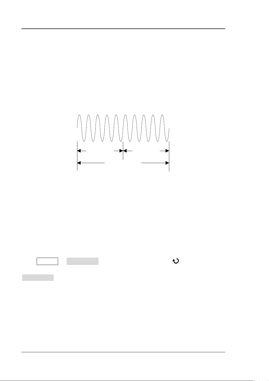
RIGOL Chapter 4 Sample System Setting
T
Trigger Point
Pre-sample
Delayed Sample
Memory Depth
To Set the Memory Depth
The memory depth refers to the number of waveform points that the oscilloscope
can store in a single trigger sample and it reflects the storage ability of the
acquisition memory. DS4000E provides up to 14 Mpts memory d epth for each
channel.
The relation of the memory depth, sample rate and waveform length fulfills the
equation below:
Memory Depth = Sample Rate × Waveform Length
Wherein, Waveform Length = Horizontal Time Base × number of grids horizontally
on the screen. F or DS4000E, the number of grids h orizontally on the screen is alwa ys
14. Therefore, with the same h orizontal t ime base, h igher memo ry depth can e nsure
higher sample rate.
Press Acquire Mem Depth, turn the multi-function knob to select the
desired mem ory depth (t he def ault is auto ); then, press the knob. You can also press
Mem Depth continuously to switch the current memory depth.
The memory depth can be set to Auto, 7 kPoints, 70 kPoints, 700 kPoints and 7
MPoints.
In “Auto” mode, the oscilloscope selects the memory depth automatically
according to the current sample rate. As the sample rate might change when
adjusting the horizontal time base, the memory depth might also change
accordingly.
4-6 DS4000E User’s Guide
Page 87

Chapter 4 Sample System Setting RIGOL
To Turn Anti-aliasing On/Off
At slower sweep speed, the sample rate is reduced and the possibility of aliasin g can
be minimized by using a dedicated display algorithm.
Press Acquire and press Anti-Aliasing to turn the anti-aliasing function on or off
(the default is off). The display e d waveforms will be more susceptible to aliasing
when this function is off.
DS4000E User’s Guide 4-7
Page 88

Page 89

Chapter 5 Trigger RIGOL
Chapter 5 Trigger
To ge nera te a t rigger, you set a trigger condition accordin g to the requi rement; when
a waveform in the waveform stream meets this condition, the oscilloscope captures
this waveform as well as the neighbouring part immediately and then displays the
captu red wav efo rm s on the screen. The digital oscilloscope samples wave for m d a t a
continuously no matter whether it is stab ly triggered; but only a stable trigger can
guarantee stable waveform display. The trigger circuit guarantees that each time
sweep and sample start w hen the input s ignal meets the trigger condition defined by
users; namely each sweep and sa mple are synchronous and the waveforms acquired
overlap to display a stable waveform. The trigger setting should be based on the
features of the input signal; thus you need to have some knowledge of the signal
under test to quickly capture the desired waveform. This oscilloscope provides
abundant advanced trigger functions which can h elp you to focus on t he wavefo rm
details of interest.
The contents of this chapter:
Trigger Source
Trigger Level
Trigger Mode
Trigger Coupling
Trigger Holdoff
Noise Rejection
Trigger Output Connector
Edge Trigger
Pulse Trigger
Runt Trigger
Nth Edge Trigger
Slope Trigger
Video Trigger
Pattern Trigger
RS232 Trigger
I2C Trigger
SPI Trigger
CAN Trigger
FlexRay Trigger
LIN Trigger (Option)
USB Trigger
DS4000E User’s Guide 5-1
Page 90
RIGOL Chapter 5 Trigger
Trigger Source
Signals input from the channels (CH1 to CH4), the external trigger input terminal
[EXT TRIG] connector and the AC Line can all be used as trigger source.
Press MENU (in the trigger control area (TRIGGER) at the front panel) Source
and turn the multi-function knob to select the desired trigger source. You can
also press Source continuously to switch the current trigger source.
CH1 to CH4
Signals input from the channels (CH1 to CH4) can all be used as the trigger
source. No matter whether the channel selected is turned on, the channel can
work normally.
External trigger input
Signals (such as external clock and signal of the circuit to be tested) input from
the external trigger input terminal ([EXT TRIG] connector) at the front panel
can be used as the trigger source. When this type of trigger source (EXT or
[1]
EXT/5
-800 mV to +800 mV.
Note
TRIG] connector) by 5 times.
AC line
The trigger signal is obtained from the AC power input of the oscilloscope. This
trigger source can be used to display the relationship between the signal (such
as illuminating de vice) an d power ( power suppl y de vice). For example, to stably
trigger the waveform output from the transformer of a transformer substa t i o n;
this is mainly used in related measurement of the power industry.
Note: When different trig ger ty pe is selected, t he si gnal sour ces (one or more of the
signals mentioned above) available are different.
) is selected, turning TRIGGER LEVEL can set a t rigger level from
[1]
: EXT/5 refers to attenuating the signal input from the external input terminal ([EXT
5-2 DS4000E User’s Guide
Page 91
Chapter 5 Trigger RIGOL
Trigger Level
The adjustment of the trigger level is related to the trigger source type.
When the trigger source is any of CH1 to CH4, rotate TRIGGER
adjust the trigger level.
During the adjustment, a trigger level line (orange dotted line) and a trigger
label (
variation of the trigger level. At the same time, the trigger level information (as
shown in the figure below) pops up at the lower-left side of the screen in
real-time. The trigger level line and trigger level information at the lower-left
side of the screen disappears about 2 s later after you stop m odifying the trigger
level. The current tri gger lev el is displa ye d at t he up per-right side of the screen.
Note: For runt trigger and slo pe trigger, you need to set the trigger level upper
limit and trigger level lower limit. You can turn TRIGGER
the value of the specified trigger level. The difference between the current
upper limit and lower limit of the trigger leve l is displ ay ed at th e uppe r-right side
of the screen. Two trigger level labels (
the screen.
When the trigger source is EXT or EXT/5, turn TRIGGER
the trigger level.
During the adjustment, the trigger level information pops up at the lower-left
side of the screen in real-time and disappears about 2 s later after you stop
modifying the trigger level. The current trigger level is displayed at the
upper-right side of the screen.
When the trigger source is AC line, there is no trigger level.
) are displayed on the screen; they move up and down with the
LEVEL to adjust
and ) are displayed at the right of
LEVEL to ad just
LEVEL to
DS4000E User’s Guide 5-3
Page 92
RIGOL Chapter 5 Trigger
Trigger Mode
DS4000E provide s Auto, Norma l and Single trigger modes and the default is Auto.
Pressing MODE in the trigger control a rea (TRIGGER) at the front pa ne l can quickly
switch the current trigger mode. You can also press MENU (in the trigger control
area (TRIGGER) at the front panel) Sweep and turn the multi-function knob
to select the desired trigger mode; or press Sweep continuously to switch the
current trigge r m ode. The corresponding status light of the trigger mode currently
selected in the trigger control area (TRIGGER) at the front panel turns on.
Auto: in this trigger mode, the oscilloscope will trigger, sample and display
waveform forcibly if no specified trigger condition is found.
This trigger mode should be used when the signal level is unknown or the DC
should be displayed as well as when forcible trigger is not necessary as the
trigger condition always occurs.
Normal: in this trigger mode, the oscilloscope triggers and samples data only
when the specified trigger condition is found.
This trigger mode should be used when the signal is with low re petiti on rat e or
only the event specified by the trigger setting needs to be sampled as well as
when auto trigger should be prevented to acquire stable display.
Single: in this trigger mode, the oscilloscope performs a single trigger and
acquisition when the specified trigger condition is found and then stops.
This trigger mode should be use d when you ne ed to perform a single acquisiti on
of the specified event and analyze the acquisition res ult (y ou can pan and zoo m
the waveform currently displayed and the subsequent waveform data will not
overwrite the current waveform).
Note: In Normal and Single trigger modes, pressing FORCE can force a trigger.
5-4 DS4000E User’s Guide
Page 93
Chapter 5 Trigger RIGOL
Trigger and the Pre-trigger/Post-t rigger Buffer
The following is the schematic diagram of the acquisition memory. To easily
understand the trigger event, the acquisition memory is divided into the pre-trigger
buffer an d pos t-trigger buffer.
Trigger Event
Pre-trigger Buffer Post-trigger Buffer
Acquisition Memory
After the system runs, the oscilloscope operates by first filling the pre-trigger buffer.
It starts searching for a trigger after the pre-trigger buffer is filled. While searching
for the trigger, the oscilloscope overflows the pre-trigge r buffer and t he first data put
into the buffer is first pushed out (FIFO). When a trigger is found, the pre-trigger
buffer contains the data acquired just before the trigger. Then, the oscilloscope will
fill the post-trigger buffer and display the data in the acquisition memory. If the
acquisition is activated via RUN/STOP, the oscilloscope will repeat this process; if
the acquisition is activated via SINGLE, the oscilloscope will stop after finishing a
single acquisition (you can pan and zoom the waveform currently displayed).
DS4000E User’s Guide 5-5
Page 94
RIGOL Chapter 5 Trigger
Trigger Coupling
The trigger coupling setting determines the type of signal components that will be
transmitted to the trigger circuit.
Press MENU (in the trigger control area (TRIGGER) at the front panel) Setting
Coupling and turn the multi-function knob to select the desired coupling
type (the def ault is DC). You can also press Coupling continuously to switch the
current coupling mode.
DC: allow DC and AC components into the trigger path.
AC: block the DC components and attenuate signals lower than 8 Hz.
LF Reject: block the DC components and reject the low-frequency components
lower than 5 kHz.
HF Reject: reject the high-frequency components higher than 50 kHz.
Note: Trigger coupling has no relation with channel coupling (r e fer t o “To Specify
the Channel Coupling”).
5-6 DS4000E User’s Guide
Page 95
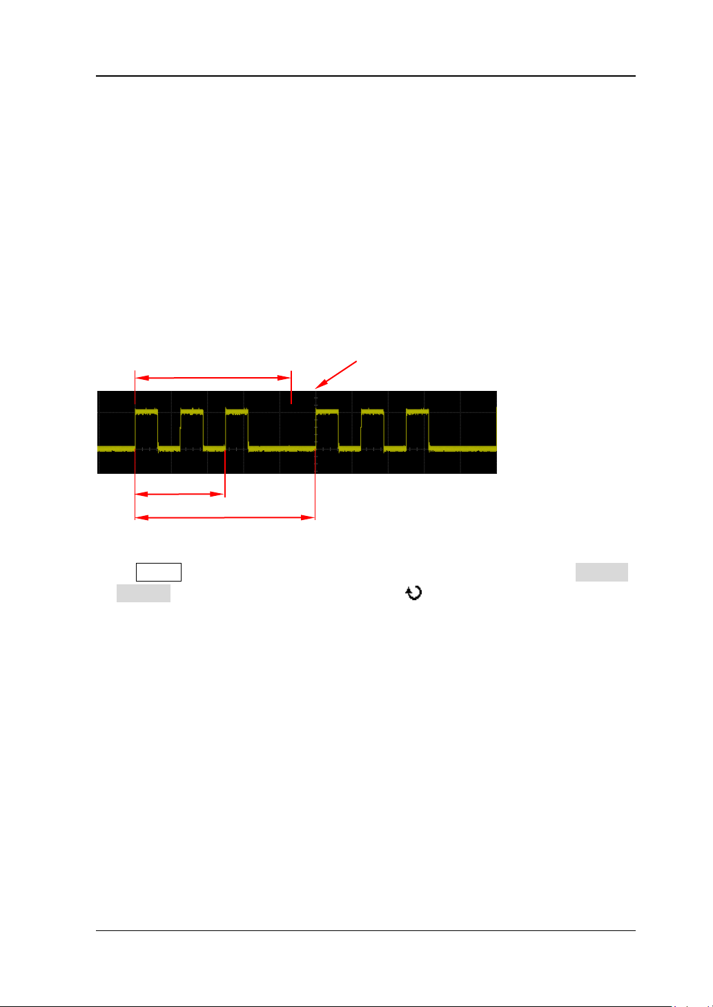
Chapter 5 Trigger RIGOL
Trigger Holdoff
The trigger holdoff can be used to set the period of time that the oscilloscope waits
(namely the holdoff time) before re-arming the trigger circuitry after a trigger. The
oscilloscope will not trigger until the holdoff time e xpires. Trigger holdoff can be used
to stably trigger complex repeat waveforms (there are multiple edges (or other
events) within a single repeating period of the waveform, such as pulse series).
For example, to stably trigger the repeat pulse series as shown in the figure below,
the holdoff time should be set to a value greater than t1 and lower than t2.
Holdoff Time
Trigger Position
t1
t2
Press MENU (in the trigger control area (TRIGGER) at the front panel) Setting
Holdoff; then, turn the multi-function knob or the inner knob of the
navigation knob to modify the holdoff time at a relatively smaller step or turn the
outer knob of the na vigation knob to adjust the hold off time at a relatively larger ste p
until the trigger becomes stable. The adjustable range is from 100 ns to 10 s. The
default is 100 ns.
Note:
Trigger types that support trigger holdoff include “Edge Trigger”, “Pulse
Trigger”, “Runt Trigger”, “Slope Trigger” and “Pattern Trigger”.
The larger the rotation amplitude of the outer knob of the navigation knob is,
the faster the va riation of the v al ue will be. When yo u need t o adjust the h oldof f
time within a relatively l arger range, thi s function can hel p you quickly finish the
setting.
DS4000E User’s Guide 5-7
Page 96
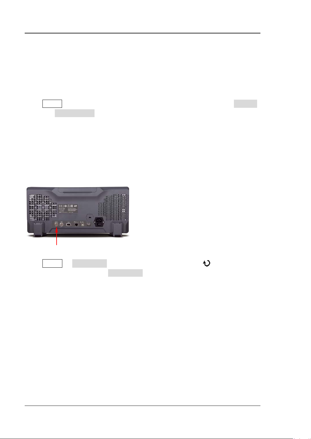
RIGOL Chapter 5 Trigger
Noise Rejection
Noise rejecti on reduces the possibility of noise triggering by increasing the trigger
hysteresis.
Press MENU (in the trigger control area (TRIGGER) at the front panel) Setting
and press Noise Reject to turn the noise rejection on or off.
Trigger Output Connector
The trigger output connector [Trig Out/Calibration] at the rear panel of the
oscilloscope can output trigger signal determined by the current trigger setting.
Trigger Output Connector
Press Utility AuxOutput and turn the multi-function knob to select
“TrigOut”. You can also press AuxOutput continuously to switch to “TrigOut”. Each
time the oscilloscope is triggered, it outputs a signal that can reflect the current
capture rate of t he oscillosco pe via the [ Trig O ut /C al ibr atio n ]. Con nect the signal
to a waveform display device and measure its frequency; the measurement result
should be equal to the current capture rate.
5-8 DS4000E User’s Guide
Page 97
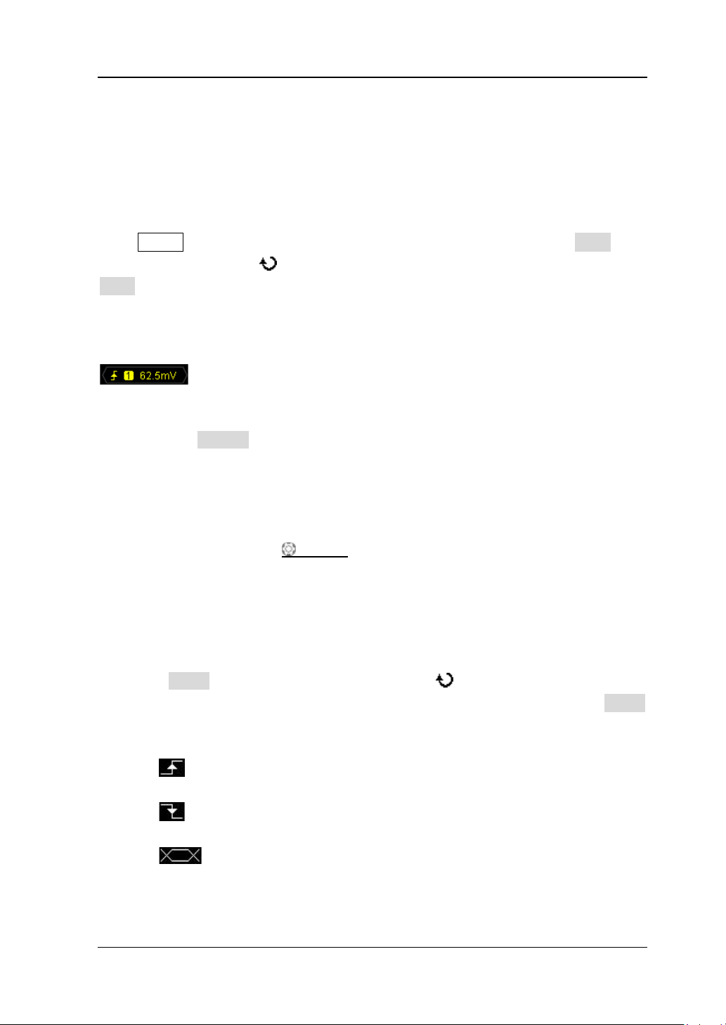
Chapter 5 Trigger RIGOL
Edge Trigger
In edge trigger, the oscilloscope triggers on the trigger level of the specified edge of
the input signal.
Press MENU (i n the trigger control area (TRIGGER) at the front panel) Type, turn
the multi-function knob to select “Edge” and press the knob. You can also press
Type continuously to switch to “Edge” trigger.
At this point, the trigger setting information (include the trigger type, trigger source
and trigge r level, as show n in the figure below) is displayed at the upper-right side of
the screen and changes with the trigger setting.
1. Specify the trigger source and adjust the trigger lev el
1) Press Source to select CH1 to CH4, EXT, EXT/5 or AC Line (please refer to
“
Trigger Source”). The tri gger source currently selected is displayed at
the upper-right side of the screen.
Note: Channels that are turned off can also be select ed as the trigger
source.
2) Rotate TRIGGER
“
Trigger Level”). The current trigger level is displayed at the upper-right
side of the screen.
Note: When the trigger source is AC line, there is no trigger level.
2. Specify the edge type
Press Slope and turn the multi-function knob to selec t th e kind o f edge o f
the input signal on which the oscilloscope triggers. You can also press Slope
continuously to switch the current edge type. The edge type currently selected is
displayed at the upper-right side of the screen.
: trigger on the rising edge of the input signal when the voltage level
meets the preset trigger level.
: trigger on the falling edge of the input signal when the voltage level
meets the preset trigger level.
: trigger on the rising and falling edges of the input signal when the
voltage level meets the preset trigger level.
LEVEL to adjust the trigger level (please refer to
DS4000E User’s Guide 5-9
Page 98
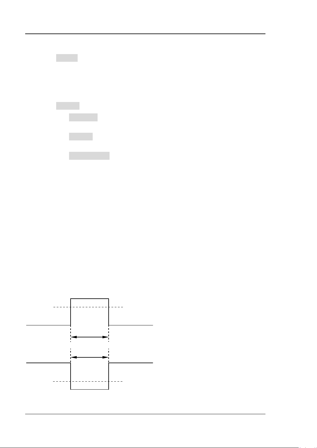
RIGOL Chapter 5 Trigger
A
B
A
B
3. Specify the trigger mode
Press Sweep to select “Auto”, “Normal” or “Single” (please refer to “Trigger
Mode”). The corresponding stat us light of t he trigger mode currently selected in
the trigger control area (TRIGGER) at the front panel turns on.
4. Set the trigger coupling, trigger holdoff and noise rejection
Press Setting to enter the trigger setting submenu. In this submenu:
1) Press Coupling to select “DC”, “AC”, “LF Reject” or “HF Reject” (please
refer to “
Trigger Coupling”).
2) Press Holdoff to adjust the holdoff time (please refer to “Trigger
Holdoff”). The range is from 100 ns to 10 s.
3) Press Noise Reject to turn the noise rejection on or off (please refer to
“
Noise Rejection”).
Pulse Trigger
In pulse trigger, the oscilloscope triggers on the positive or negative pulse with a
specif ied width.
For this oscilloscope, the positive pulse width is defined as the time difference
between the two crossing points of the trigger level and positive pulse and the
negative pulse width is defined as the time difference between the two crossing
points of the trigger level and negative pulse, as shown in the figure below.
Trigger Level
Positive
Pulse Width
Negative
Pulse Width
Trigger Level
5-10 DS4000E User’s Guide
Page 99
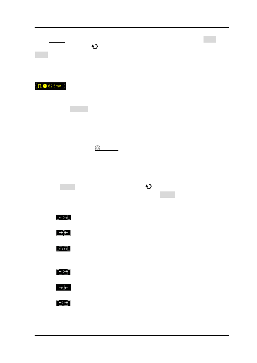
Chapter 5 Trigger RIGOL
Press MENU (i n the trigge r control area (TRIGGER) at the front panel) Type, turn
the multi-function knob to select “Pulse” and press the knob. You can also press
Type continuously to switch to “Pulse” trigger.
At this point, the trigger setting information (include the trigger type, trigger source
and trigger level, as show n in the figure below) is displayed a t the u pper-right side of
the screen and changes with the trigger setting.
1. Specify the trigger source and adjust the trigger level
1) Press Source to select CH1 to CH4 or EXT (please refer to “Trigger
Source”). The trigger source currently selected is displayed at the
upper-right side of the screen.
Note: Channels that are turned off can also be selected as the trigg er
source.
2) Turn TRIGGER
“
Trigger Level”). The current trigger level is displayed at the upper-right
LEVEL to ad just the trigger level (please refer to
side of the screen.
2. Specify the pulse width condition
Press When, turn the multi-function knob to select the desired pulse width
condition and press the knob. You can also press When continuously to switch
the current pulse width condition. The pulse type of the pulse width condition
currently selected is displayed at the up per-right side of the screen.
: trigger when the positive pulse width of the input signal is greater
than the specified pulse width setting.
: trigger when the positive pulse width of the input signal is lower
than the specified pulse width setting.
: trigger when the positive pulse width of the input signal is greater
than the specified lower limit of pulse width and lower than the upper limit
of pulse width.
: trigger when the negative pulse width of the input signal is greater
than the specified pulse width setting.
: trigger when the negative pulse width of the input signal is lower
than the specified pulse width setting.
: trigger when the negative pulse width of the input signal is greater
than the specified lower limit of pulse width and lower t han the upper limit
of pulse width.
DS4000E User’s Guide 5-11
Page 100
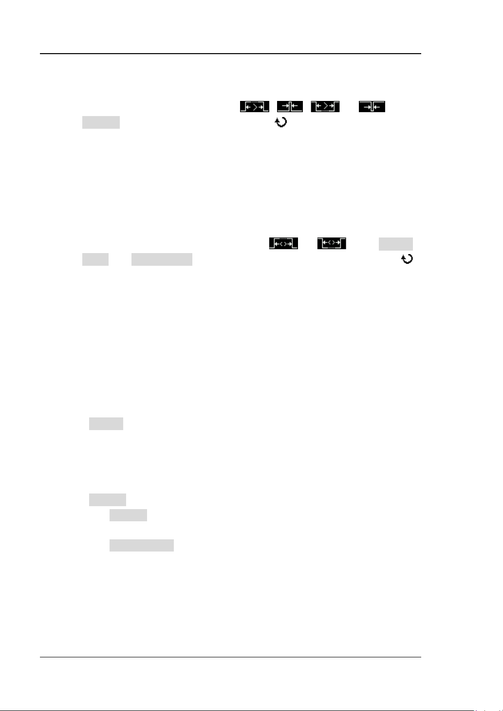
RIGOL Chapter 5 Trigger
3. Specify the pulse width range
The pulse width range is related to the current pulse width condition setting.
When the pulse width condition is
, , or , press
Setting and turn the multi-function knob o r the inner knob o f t h e
navigation knob to adjust the pulse width at a relatively smaller st ep or turn
the outer knob of the navigation knob to adjust the pulse width at a
relatively larger step. The range available is from 4 ns to 4 s.
Note: The larger the rotation a mplitude of the o uter knob of the na vigation
knob is, the faster the variation of the value will be. When you need to
adjust the pulse width within a relatively l arger range, this functi on can hel p
you quickly finish the setting.
When the pulse width condition is set to or , press Upper
Limit and Lower Limit respectively and use the multi-function knob
or the navigation knob to adjust the upper limit and lower limit of pulse
width. The range of the upper limit is from 12 ns to 4 s. The range of the
lower limit is from 4 ns to 3.99 s.
Note:
― The lower limit of the pulse width must be lower than the upper limit.
― You can use the outer knob of the navigation knob to quickly adjust the
upper limit and lower limit of pulse width within a relatively larger
range.
4. Specify the trigger mode
Press Sweep to select “Auto”, “Normal” or “Single” (please refer to “Trigger
Mode”). The corresponding status light of the trigger mode currently selected in
the trigger control area (TRIGGER) at the front panel turns on.
5. Set the trigger holdoff and noise rejection
Press Setting to enter the trigger setting submenu. In this submenu:
1) Press Holdoff to adjust the holdoff time (please refer to “Trigger
Holdoff”). The range is from 100 ns to 10 s.
2) Press Noise Reject to turn the noise rejection on or off (please refer to
“
Noise Rejection”).
5-12 DS4000E User’s Guide
 Loading...