

Page 1

RIGOL
Calibration Guide
DS4000 Series Digital Oscilloscope
Feb. 2014
RIGOL Technologies, Inc.
Page 2

Page 3

RIGOL
I
Guaranty and Declaration
Copyright
© 2012 RIGOL Technologies, Inc. All Rights Reserved.
Trademar k I n formation
RIGOL is a registered trademark of RIGOL Technologies, Inc.
Publication Number
CGA10101-1110
Notices
RIGOL products are protected by patent law in and outside of P.R.C.
RIGOL reserves the right to modify or change part s of or all the speci fications and pricing
policies at company’s sole decisi on.
Inform ation in this publication rep laces all prev iously corre sponding mat erial.
RIGOL shall not be liable for losses cau sed by ei ther inci d en tal or consequential in conne cti on
with the furnishing, use or performa nce of this manual as well as any information contained.
Any part of thi s document is forbidden to be copied or photocopied or rearranged without prior
writte n appr o v al of RIGOL.
Product Certification
RIGOL guarantees this product confor m s to the nation al and industrial standards i n China.
International stand ard conformance certification is in progress , e. g. ISO.
Contact Us
If you have any problem or requirement when using our products or this manual, please contact
RIGOL.
E-mail: service@rigol.com
Website: www.rigol.com
DS4000 Calibration Guide
Page 4

RIGOL
II
Contents
Guaranty and Declaration .................................................................................................... I
Document Ov er v ie w ......................................................................................................... III
Chapter 1 Calibration Notices ....................................................................................... 1-1
Calibration Preparations .................................................................................................. 1-1
Project Mode ................................................................................................................. 1-2
Calibration Sequence ...................................................................................................... 1-3
To Resume Calibration .................................................................................................... 1-3
Chapter 2 Calibration Procedures ................................................................................. 2-1
Self-Calibration (Vertical Calibration) ................................................................................ 2-1
Equiv alent Calibration ..................................................................................................... 2-2
Delay Calibration ............................................................................................................ 2-3
DS4000 Calibration Guide
Page 5

RIGOL
III
Document Overv ie w
This document mainly intr oduces h ow to calibrate the RIGOL DS4000 oscill oscope in i ts proje ct mod e.
It is assumed that readers of this document are familiar with the front and rear panels and the
operation method of DS4000. DS4000 includes dual-channel and four-channel models and in this
manual the four-channel model is taken as an example for the illu stration.
DS4000 Calibration Guide
Page 6

Page 7
Chapter 1 Calibration Notices RIGOL
1-1
Chapter 1 Calibration Notices
Calibration Pre pa r at ions
RIGOL DS4000 oscilloscope
RIGOL DG5000 signal generator
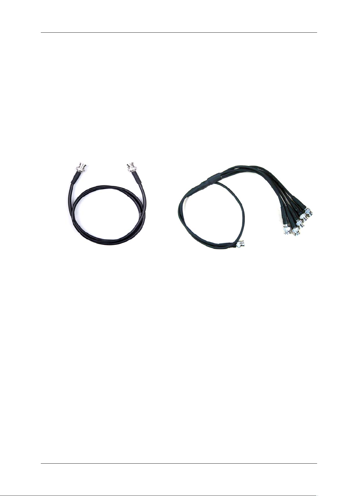
A BNC cable (Figure 1)
A BNC one-to-five cable (Figure 2)
Note: make sure the instrument has been warmed up for 3 0 minutes before calibrating.
Figure 1
Figure 2
DS4000 Calibration Guide
Page 8

RIGOL Chapter 1 Calibration Notices
1-2
Repe ating step 2 a nd 3 can r etur n
Project Mode
1. Start the oscilloscope.
2. Press MENU in the TRIGGER con trol area at t he lower-right corner of the front panel and then
set the trigger Type to “Edge”.
3. Press F7, F6, F7 and Utility (F7 and F6 are defined as shown in Figure 3) successiv el y to en ter
the project mode and sel ect t he second -page menu (Figure 4). (
back to the normal mode).
Note: by default, the oscilloscope enters the normal mode after restart.
F6
F7
Figure 3
Figure 4
DS4000 Calibration Guide
Page 9

Chapter 1 Calibration Notices RIGOL
1-3
At
minute Warm-up
Self-Calibration
Equivalent Calibration
Delay Calibration
Finish
Calibration Sequence
The calibration sequence is as shown in the figure below. It is recommended to calibrate the
instrum ent fo ll ow i ng t he Self-Calibration, Equivalent Calibration, Delay Calibration sequence,
wherein, equivale nt cali bration and delay calibration must be performed in project mode.
Least 30-
To Resume Calibration
Select ResumeCal to restore the oscilloscope to its default parameters when the calibration fails or
the oscilloscope fails to save the parameters.
DS4000 Calibration Guide
Figure 5
Page 10

Page 11
Chapter 2 Calibration Procedures RIGOL
2-1
Chapter 2 Calibration Procedure s
Self-Calibration ( Ve rtical Calibration)
Make sure the oscilloscope has been warmed up for 30 minut es before performing self-calibration.
Then, f ollow the steps below to calibr ate the instrum ent.
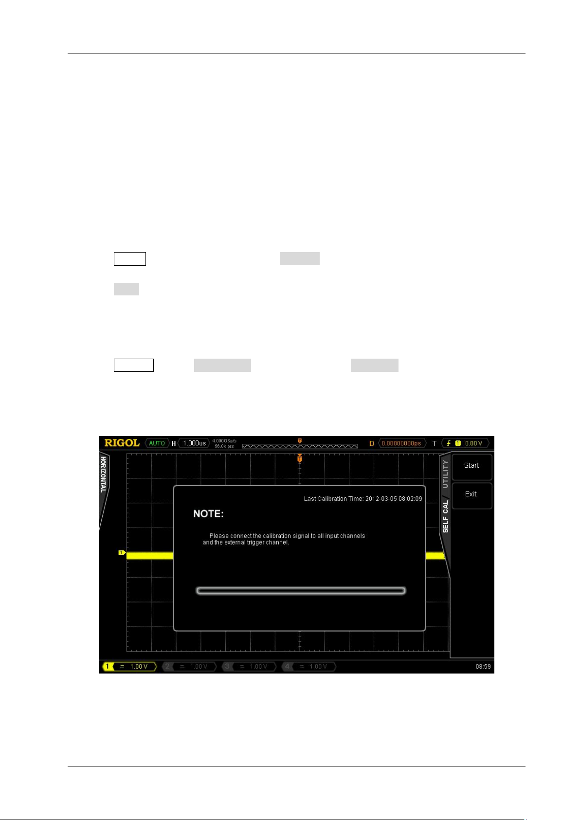
1. Connec t all the input channels and external trigger channel of the oscilloscope to the [Trig
Out/Calibration] connector at the rear panel using the BNC One-to-Five Cable.
2. Press Utility at the fr o nt pa nel and s ele ct Self-Cal in the first-page menu.
3. Press Start to perform self-calibration (as s hown in Figure 6).
4. The self-cali br atio n wo uld last for abo ut 3 0 mi nut es (2 0 mi nut es f or d ual-channel models). Restart
the oscilloscope when “Calibration finished, please restart the oscilloscope!” is displayed.
5. Press Acquire, set the Acquisition to “Average” and the Averages to 16.
6. Disconn ect the i nput sig nals of all the chann els to view the off set of the w avef orm of each c hannel
at 2mV/div scale. Calibrate again if the offset exceeds 0.5div.
Figure 6
DS4000 Calibration Guide
Page 12

RIGOL Chapter 2 Calibration Procedures
2-2
Equivalent Calibratio n
Make sure the oscilloscope has been warmed up for 30 minutes before performing equivalent
calibration. Then, follow the st eps below to calibrate the instrume nt.
1. Disconnect all the channels as well as the external trigger channel. Enter the proj ect mode and
select EqualCal (Figure 4) to star t the calibration.
2. The equivalent calibrati on would last for about 1 minute. Restar t the oscilloscope when
“Calibration finished, please restart the oscilloscope!” is display ed.
3. Con nec t CH1 of the os cill o scop e to the [Tri g Out/Calibration] connector at the rear panel
using the BNC Cable.
4. Press Utility, enter the second-page me nu and pr es s AuxOutput to select “Fast”.
5. Press CH1 and set the input impedance of CH1 to 50 Ω and the vertical scale to 200 mV/di v.
Adjust th e trigger level t o get stable wav eform. Adjust the vertical position of CH1 to display the
waveform within t he screen range.
6. Observe whether jitter occurs at the signal trigger position at 10 ns and 2 ns horizontal scale s
respectively. If yes , calibr ate agai n. The norm al calibr ation waveform should be as show n in Fig ure
7.
Figure 7
DS4000 Calibration Guide
Page 13

Chapter 2 Calibration Procedures RIGOL
2-3
Delay Calibration
Make sure the oscilloscope has been warmed up for 30 minutes before performin g delay calibration.
Then, f ollow the steps below to calibrate the instrument.
1. Output a sq uare w avefor m with 100 kHz freq uency, 4 Vpp amplitude and 50 Ω impedance from the
signal generator.
2. Connect the above-m ention ed signal to al l the input c hannels (except t he exter nal trigg er channel )
of the oscillosc ope usi ng t he BNC One-to-Five C able.
3. Enter the second-page menu (Figure 4) of the proj ect mode and select DelayCal to start the
calibration.
4. The del ay calibratio n would last for about 2 minut es. Restart t he oscilloscope when the
“Calibration finished, please restart the oscilloscope!” message is displayed.
5. Set the time base to the minimum s cale (500MHz oscilloscope: 1ns scale; 350 MHz and 200 MHz
oscillosc ope s: 2 ns scale; 100MHz oscilloscope: 5 ns scale) and set the vertical scale and i n put
impedance of each channel to 500 mV/div and 50 Ω respectively to view whether offset to the zero
point of the waveform of each channel occurs. If yes, calibrate again. The fail ed waveform is as
shown in Figure 8.
6. Keep t he tim e bas e set ting unc hang ed . Turn all the channel s on, th en tu rn an y of t he cha nnel s o ff
and view w hether other ch annels are affected and wheth er the waveforms jump. If yes, perform
delay calibration ag ain. The normal waveform should be as s hown in Figure 9.
Figure 8
DS4000 Calibration Guide
Page 14

RIGOL Chapter 2 Calibration Procedures
2-4
Figure 9
By now, the calibration finishes.
DS4000 Calibration Guide
 Loading...