

Page 1

RIGOL
Programming Guide
DS4000E Series Digital Oscilloscope
Aug. 2016
RIGOL TECHNOLOGIES, INC.
Page 2

Page 3

RIGOL
Guaranty and Declaration
Copyright
© 2016 RIGOL TECHNOLOGIES, INC. All Rights Reserved.
Trademark Information
RIGOL is a registered trademark of RIGOL TEC H NO LOGI ES, INC .
Publication Number
PGA21101-1110
Software Version
00.02.03
Software upgrade might change or add product features. Please acquire the latest version of the manual
from RIGOL website or contact RIGOL to upgrade the software.
Notices
RIGOL products are covered by P.R.C. and foreign patents, issued and pending.
RIGOL reserves the right to modify or change parts or all of the specifications and pricing policies at
the company's sole decision.
Information in this publication replaces all previously released ma terials.
Information in this publication is subject to change without notice.
RIGOL shall no t be liable for either incidental or consequential losses in connection with the furnishing,
use, or performance of this manual as well as any information contained.
Any par t of this document is forbidden to be copied, photocopied, or rearranged without prior written
approval of RIGOL.
Product Certification
RIGOL guarantees that this product conforms to the n ational and industrial standards in China as well as
the ISO9001:2008 standard and the ISO14001:2004 standard. Other international standard conformance
certifications are in progress.
Contact Us
If you have any problem or requirement when using our products or this manual, please contact RIGOL.
E-mail: service@rigol.com
Website: www.rigol.com
DS4000E Programming Guide I
Page 4

RIGOL
Tip
RIGOL
Document Overview
This manual is your guide to programming RIGOL DS4000E series digital os cilloscope.
For the newest version of this manual, please download it from
official website (www.rigol.com).
Main Topics in this Manual:
Chapter 1 SCPI Command Overview
This chapter introduces the syntax, symbols, paramet ers, and abbreviation rules of the SCPI commands.
Chapter 2 Command System
This chapter introduce s the syntax, function, parameters, and usage of each command.
Chapter 3 Programming Examples
This chapter illustrates how t o control the DS400 0E series digital oscilloscope by programming i n Excel,
LabVIEW, MATLAB, Visual Basic 6.0, and Visual C++ 6.0.
Format Conventions in this Manual:
1. Function Key
The key on the front panel is denoted by the format of “Key Name (Bold) + Text Box” in the manual.
For example, Utility denotes the "Utility" key.
2. Menu Softkey
The menu softkey is denoted by the format of "Menu Name (Bold) + Character Shading" in the manual.
For example, System denotes the "System" softkey under Utility.
3. Operation Procedures
The next step is denoted by the arrow key (""). For example, Utility System denotes that first
press Utility, and then press the System softkey.
Content Conventions in this Manual:
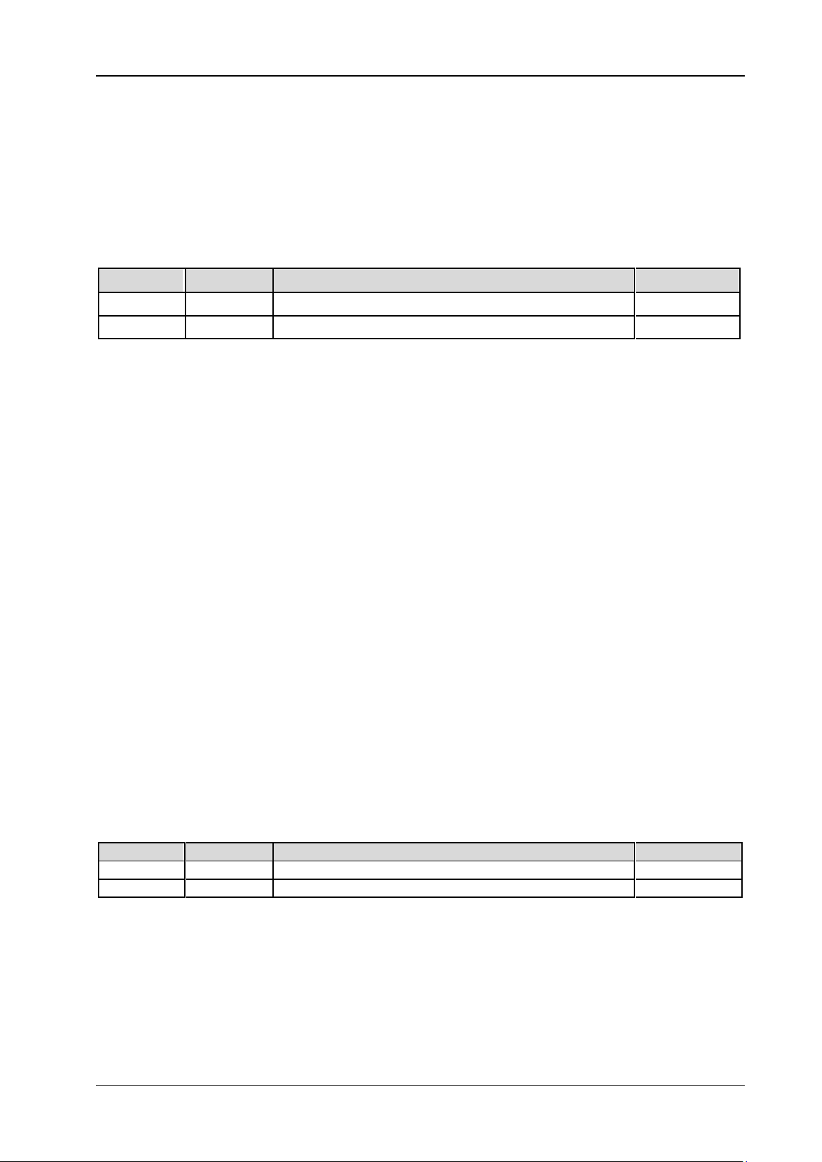
DS4000E series includes the following models. Unless otherwise specified, this manua l takes DS4024E as
an example to make a detailed introduction about the commands of DS4000E series.
Model
DS4024E
DS4014E
Bandwidth
200 MHz
100 MHz
No. of Channels
4
4
II DS4000E Programming Guide
Page 5

Contents RIGOL
Contents
Guaranty and Declaration ......................................................................................................... I
Document Overview ................................................................................................................. II
Chapter 1 SCPI Command Overview .................................................................................. 1-1
Syntax ..................................................................................................................................... 1-1
Symbol Description ................................................................................................................... 1-1
Parameter Type ........................................................................................................................ 1-2
Command Abbreviation ............................................................................................................. 1-2
Chapter 2 Command System ............................................................................................... 2-1
:AUToscale ............................................................................................................................... 2-1
:CLEar...................................................................................................................................... 2-2
:RUN ........................................................................................................................................ 2-2
:STOP ...................................................................................................................................... 2-2
:SINGle .................................................................................................................................... 2-2
:TFORce ................................................................................................................................... 2-3
:TLHAlf .................................................................................................................................... 2-3
:ACQuire Commands ................................................................................................................. 2-4
:ACQuire:AALias ................................................................................................................. 2-4
:ACQuire:AVERages ............................................................................................................ 2-4
:ACQuire:MDEPth ............................................................................................................... 2-5
:ACQuire:SRATe? ................................................................................................................ 2-5
:ACQuire:TYPE ................................................................................................................... 2-5
:BUS<n> Commands ................................................................................................................ 2-7
:BUS<n>:DATA? ................................................................................................................ 2-7
:BUS<n>:DISPlay .............................................................................................................. 2-8
:BUS<n>:EEXPort .............................................................................................................. 2-8
:BUS<n>:EVENt ................................................................................................................ 2-8
:BUS<n>:FORMat .............................................................................................................. 2-9
:BUS<n>:MODE ................................................................................................................ 2-9
:BUS<n>:CAN (Option) .................................................................................................... 2-10
:BUS<n>:FLEXray (Option) .............................................................................................. 2-14
:BUS<n>:IIC (Option) ...................................................................................................... 2-17
:BUS<n>:PARallel ............................................................................................................ 2-20
:BUS<n>:RS232 (Option) ................................................................................................. 2-23
:BUS<n>:SPI (Option) ..................................................................................................... 2-30
:CALCulate Commands ............................................................................................................ 2-38
:CALCulate:MODE ............................................................................................................ 2-38
:CALCulate:ADD ............................................................................................................... 2-39
:CALCulate:ADVanced ...................................................................................................... 2-41
:CALCulate:DIVision ......................................................................................................... 2-44
:CALCulate:FFT ................................................................................................................ 2-46
:CALCulate:LOGic ............................................................................................................. 2-51
:CALCulate:MULTiply ........................................................................................................ 2-54
:CALCulate:SUB ............................................................................................................... 2-56
:CALibrate Commands ............................................................................................................. 2-58
:CALibrate:DATE? ............................................................................................................. 2-58
:CALibrate:QUIT .............................................................................................................. 2-58
:CALibrate:STARt ............................................................................................................. 2-58
:CALibrate:TIME? ............................................................................................................. 2-59
:CHANnel<n> Commands ....................................................................................................... 2-60
:CHANnel<n>:BVOLtage .................................................................................................. 2-60
:CHANnel<n>:BWLimit ..................................................................................................... 2-60
:CHANnel<n>:COUPling ................................................................................................... 2-61
:CHANnel<n>:CSTart ....................................................................................................... 2-61
DS4000E Programming Guide III
Page 6

RIGOL Contents
:CHANnel<n>:DISPlay ...................................................................................................... 2-62
:CHANnel<n>:IMPedance ................................................................................................. 2-62
:CHANnel<n>:INVert ........................................................................................................ 2-62
:CHANnel<n>:OFFSet....................................................................................................... 2-63
:CHANnel<n>:PEND ......................................................................................................... 2-63
:CHANnel<n>:PROBe ....................................................................................................... 2-64
:CHANnel<n>:SCALe ........................................................................................................ 2-64
:CHANnel<n>:TCALibrate ................................................................................................. 2-65
:CHANnel<n>:TYPE? ........................................................................................................ 2-65
:CHANnel<n>:UNITs ........................................................................................................ 2-65
:CHANnel<n>:VERNier ..................................................................................................... 2-66
:CURSor Commands ................................................................................................................ 2-67
:CURSor:MODE ................................................................................................................ 2-68
:CURSor:MANual .............................................................................................................. 2-69
:CURSor:TRACk ................................................................................................................ 2-75
:DISPlay Commands ................................................................................................................ 2-81
:DISPlay:CLEar ................................................................................................................. 2-81
:DISPlay:DATA? ................................................................................................................ 2-81
:DISPlay:GBRightness ....................................................................................................... 2-82
:DISPlay:GRADing:TIME ................................................................................................... 2-82
:DISPlay:GRID ................................................................................................................. 2-83
:DISPlay:MPERsistence ..................................................................................................... 2-83
:DISPlay:TYPE .................................................................................................................. 2-84
:DISPlay:WBRightness ...................................................................................................... 2-84
:EXT Commands ..................................................................................................................... 2-85
:EXT:PEND ....................................................................................................................... 2-85
:EXT:CSTart ...................................................................................................................... 2-85
:FUNCtion Commands ............................................................................................................. 2-86
:FUNCtion:WRMode .......................................................................................................... 2-86
:FUNCtion:WRECord ......................................................................................................... 2-87
:FUNCtion:WREPlay .......................................................................................................... 2-89
:FUNCtion:WANalyze ........................................................................................................ 2-93
IEEE 488.2 Common Commands ............................................................................................ 2-100
*CLS .............................................................................................................................. 2-100
*ESE .............................................................................................................................. 2-100
*ESR? ............................................................................................................................ 2-101
*IDN? ............................................................................................................................ 2-101
*OPC ............................................................................................................................. 2-101
*OPC? ........................................................................................................................... 2-101
*RST ............................................................................................................................. 2-102
*SRE ............................................................................................................................. 2-102
*STB? ............................................................................................................................ 2-102
*TST? ............................................................................................................................ 2-103
:LAN Commands ................................................................................................................... 2-104
:LAN:APPLy .................................................................................................................... 2-104
:LAN:AUToip ................................................................................................................... 2-104
:LAN:DHCP .................................................................................................................... 2-105
:LAN:DNS ...................................................................................................................... 2-105
:LAN:GATeway ................................................................................................................ 2-106
:LAN:INITiate ................................................................................................................. 2-106
:LAN:IPADdress .............................................................................................................. 2-106
:LAN:MAC? ..................................................................................................................... 2-107
:LAN:MANual .................................................................................................................. 2-107
:LAN:SMASk ................................................................................................................... 2-108
:LAN:STATus? ................................................................................................................. 2-108
:LAN:VISA? .................................................................................................................... 2-108
:MASK Commands ................................................................................................................. 2-109
:MASK:CREate ................................................................................................................ 2-109
IV DS4000E Programming Guide
Page 7

Contents RIGOL
:MASK:DATA .................................................................................................................. 2-109
:MASK:ENABle ............................................................................................................... 2-110
:MASK:FAILed? .............................................................................................................. 2-110
:MASK:MDISplay ............................................................................................................ 2-110
:MASK:OPERate ............................................................................................................. 2-111
:MASK:OUTPut............................................................................................................... 2-111
:MASK:PASSed? ............................................................................................................. 2-112
:MASK:RESet ................................................................................................................. 2-112
:MASK:SOOutput ........................................................................................................... 2-112
:MASK:SOURce .............................................................................................................. 2-113
:MASK:TOTal? ................................................................................................................ 2-113
:MASK:X ........................................................................................................................ 2-113
:MASK:Y ........................................................................................................................ 2-114
:MEASure Commands ............................................................................................................ 2-115
:MEASure:ADISplay ........................................................................................................ 2-116
:MEASure:AMSource....................................................................................................... 2-116
:MEASure:AREA ............................................................................................................. 2-117
:MEASure:CLEar ............................................................................................................. 2-117
:MEASure:COUNter:SOURce ........................................................................................... 2-118
:MEASure:COUNter:VALue? ............................................................................................ 2-118
:MEASure:CREGion:CAX ................................................................................................. 2-118
:MEASure:CREGion:CBX ................................................................................................. 2-119
:MEASure:FDELay .......................................................................................................... 2-119
:MEASure:F2RDelay ....................................................................................................... 2-121
:MEASure:FPHase .......................................................................................................... 2-122
:MEASure:F2RPhase ....................................................................................................... 2-124
:MEASure:FREQuency .................................................................................................... 2-125
:MEASure:FTIMe ............................................................................................................ 2-126
:MEASure:HISTory:DISPlay ............................................................................................. 2-128
:MEASure:HISTory:DMODe ............................................................................................. 2-128
:MEASure:MARea ........................................................................................................... 2-129
:MEASure:MPARea ......................................................................................................... 2-130
:MEASure:NDUTy ........................................................................................................... 2-132
:MEASure:NWIDth ......................................................................................................... 2-133
:MEASure:OVERshoot ..................................................................................................... 2-134
:MEASure:PDUTy............................................................................................................ 2-136
:MEASure:PERiod ........................................................................................................... 2-137
:MEASure:PREShoot ....................................................................................................... 2-138
:MEASure:PVRMs ........................................................................................................... 2-140
:MEASure:PWIDth .......................................................................................................... 2-141
:MEASure:RECover ......................................................................................................... 2-143
:MEASure:RDELay .......................................................................................................... 2-143
:MEASure:R2FDelay ....................................................................................................... 2-145
:MEASure:RPHase .......................................................................................................... 2-146
:MEASure:R2FPhase ....................................................................................................... 2-148
:MEASure:RTIMe ............................................................................................................ 2-149
:MEASure:SETup:DSA ..................................................................................................... 2-151
:MEASure:SETup:DSB ..................................................................................................... 2-151
:MEASure:SETup:MAX .................................................................................................... 2-151
:MEASure:SETup:MID ..................................................................................................... 2-151
:MEASure:SETup:MIN ..................................................................................................... 2-151
:MEASure:SETup:PSA ..................................................................................................... 2-152
:MEASure:SETup:PSB ..................................................................................................... 2-152
:MEASure:SETup:TYPE ................................................................................................... 2-153
:MEASure:STATistic:DISPlay............................................................................................ 2-153
:MEASure:STATistic:MODE .............................................................................................. 2-153
:MEASure:STATistic:RESet .............................................................................................. 2-154
:MEASure:SOURce ......................................................................................................... 2-154
DS4000E Programming Guide V
Page 8

RIGOL Contents
:MEASure:VAMP ............................................................................................................. 2-155
:MEASure:VAVG.............................................................................................................. 2-156
:MEASure:VBASe ............................................................................................................ 2-158
:MEASure:VMAX ............................................................................................................. 2-159
:MEASure:VMIN.............................................................................................................. 2-161
:MEASure:VPP ................................................................................................................ 2-162
:MEASure:VRMS ............................................................................................................. 2-164
:MEASure:VTOP.............................................................................................................. 2-165
:RECall Commands ................................................................................................................ 2-167
:RECall:MTESt ................................................................................................................ 2-167
:RECall:REFerence .......................................................................................................... 2-167
:RECall:SETup ................................................................................................................ 2-168
:RECall:TRACe ................................................................................................................ 2-168
:RECall:WAVeform .......................................................................................................... 2-169
:REFerence Commands .......................................................................................................... 2-170
:REFerence:COLor .......................................................................................................... 2-170
:REFerence:CURRent? ..................................................................................................... 2-170
:REFerence:DISPlay ........................................................................................................ 2-171
:REFerence:RESet........................................................................................................... 2-171
:REFerence:SAVe ............................................................................................................ 2-171
:REFerence:SOURce ....................................................................................................... 2-172
:REFerence:VOFFset ....................................................................................................... 2-172
:REFerence:VSCale ......................................................................................................... 2-172
:REFerence<n>:CURRent ............................................................................................... 2-173
:REFerence<n>:ENABle .................................................................................................. 2-173
:SAVE Commands ................................................................................................................. 2-174
:SAVE:CSV[:STARt] ......................................................................................................... 2-174
:SAVE:CSV:FACTors ........................................................................................................ 2-174
:SAVE:CSV:LENGth ......................................................................................................... 2-175
:SAVE:FORMat ............................................................................................................... 2-175
:SAVE:IMAGe[:STARt] ..................................................................................................... 2-176
:SAVE:IMAGe:TYPE ......................................................................................................... 2-176
:SAVE:IMAGe:FACTors .................................................................................................... 2-176
:SAVE:SETup[:STARt] ..................................................................................................... 2-177
:SAVE:TRACe[:STARt] ..................................................................................................... 2-177
:SAVE:WAVeform[:STARt] ............................................................................................... 2-178
:SAVE:REFerence[:STARt] ............................................................................................... 2-178
:SAVE:MTESt[:STARt] ..................................................................................................... 2-179
:SYSTem Commands ............................................................................................................. 2-180
:SYSTem:AOUTput .......................................................................................................... 2-180
:SYSTem:AUToscale ........................................................................................................ 2-181
:SYSTem:BEEPer ............................................................................................................ 2-181
:SYSTem:DATE ............................................................................................................... 2-182
:SYSTem:ERRor[:NEXT]? ................................................................................................. 2-182
:SYSTem:ETIMpedence ................................................................................................... 2-182
:SYSTem:EXPand ............................................................................................................ 2-183
:SYSTem:GAMount? ........................................................................................................ 2-183
:SYSTem:GPIB ................................................................................................................ 2-183
:SYSTem:LANGuage ........................................................................................................ 2-184
:SYSTem:OPTion:INSTall ................................................................................................. 2-184
:SYSTem:OPTion:UNINSTall ............................................................................................ 2-184
:SYSTem:PON ................................................................................................................ 2-185
:SYSTem:PSTatus ........................................................................................................... 2-185
:SYSTem:RAMount? ........................................................................................................ 2-185
:SYSTem:RCLOck ............................................................................................................ 2-186
:SYSTem:RESet .............................................................................................................. 2-186
:SYSTem:SETup .............................................................................................................. 2-186
:SYSTem:SSAVer:TIME .................................................................................................... 2-187
VI DS4000E Programming Guide
Page 9

Contents RIGOL
:SYSTem:TIME ............................................................................................................... 2-187
:SYSTem:UDEVice .......................................................................................................... 2-188
:SYSTem:VERSion? ......................................................................................................... 2-188
:TIMebase Commands .......................................................................................................... 2-189
:TIMebase:DELay:ENABle ............................................................................................... 2-189
:TIMebase:DELay:OFFSet ............................................................................................... 2-189
:TIMebase:DELay:SCALe ................................................................................................ 2-190
:TIMebase:HREF:MODE .................................................................................................. 2-190
:TIMebase:HREF:POSition .............................................................................................. 2-191
:TIMebase:MODE ........................................................................................................... 2-191
:TIMebase:VERNier ........................................................................................................ 2-191
:TIMebase:XY1:DISPlay .................................................................................................. 2-192
:TIMebase:XY2:DISPlay .................................................................................................. 2-192
:TIMebase[:MAIN]:OFFSet.............................................................................................. 2-192
:TIMebase[:MAIN]:SCALe ............................................................................................... 2-193
:TRIGger Commands ............................................................................................................ 2-194
:TRIGger:COUPling ........................................................................................................ 2-194
:TRIGger:HOLDoff ......................................................................................................... 2-195
:TRIGger:MODE ............................................................................................................. 2-195
:TRIGger:STATus? .......................................................................................................... 2-195
:TRIGger:SWEep ............................................................................................................ 2-196
:TRIGger:NREJect .......................................................................................................... 2-196
:TRIGger:CAN ................................................................................................................ 2-197
:TRIGger:EDGe .............................................................................................................. 2-201
:TRIGger:IIC ................................................................................................................. 2-203
:TRIGger:PATTern .......................................................................................................... 2-207
:TRIGger:PULSe ............................................................................................................. 2-209
:TRIGger:RUNT ............................................................................................................. 2-212
:TRIGger:NEDGe ............................................................................................................ 2-216
:TRIGger:RS232............................................................................................................. 2-218
:TRIGger:SLOPe ............................................................................................................. 2-222
:TRIGger:SPI ................................................................................................................. 2-226
:TRIGger:USB ................................................................................................................ 2-231
:TRIGger:VIDeo ............................................................................................................. 2-234
:TRIGger:FLEXray .......................................................................................................... 2-237
:WAVeform Commands ......................................................................................................... 2-239
:WAVeform:BEGin .......................................................................................................... 2-240
:WAVeform:DATA?.......................................................................................................... 2-240
:WAVeform:END ............................................................................................................. 2-242
:WAVeform:FORMat ....................................................................................................... 2-242
:WAVeform:MODE .......................................................................................................... 2-243
:WAVeform:POINts ......................................................................................................... 2-243
:WAVeform:PREamble? ................................................................................................... 2-244
:WAVeform:RESet .......................................................................................................... 2-244
:WAVeform:SOURce ....................................................................................................... 2-245
:WAVeform:STARt .......................................................................................................... 2-245
:WAVeform:STATus? ....................................................................................................... 2-246
:WAVeform:STOP ........................................................................................................... 2-246
:WAVeform:XINCrement? ............................................................................................... 2-246
:WAVeform:XORigin? ...................................................................................................... 2-247
:WAVeform:XREFerence? ................................................................................................ 2-247
:WAVeform:YINCrement? ............................................................................................... 2-247
:WAVeform:YORigin? ...................................................................................................... 2-248
:WAVeform:YREFerence? ................................................................................................ 2-248
Chapter 3 Programming Examples ..................................................................................... 3-1
Programming Preparations ........................................................................................................ 3-1
Excel Programming Example...................................................................................................... 3-2
DS4000E Programming Guide VII
Page 10

RIGOL Contents
LabVIEW Programming Example ................................................................................................ 3-7
MATLAB Programming Example ................................................................................................ 3-11
Visual Basic 6.0 Programming Example ..................................................................................... 3-13
Visual C++ 6.0 Programming Example ..................................................................................... 3-15
VIII DS4000E Programming Guide
Page 11

Chapter 1 SCPI Command Overview RIGOL
Chapter 1 SCPI Command Overview
This chapter introduces the syntax, symbols, paramet ers, and abbreviation rules of the SCPI commands.
Contents in this chapter:
Syntax
Symbol Description
Parameter Type
Command Abbreviation
Syntax
The SCPI commands provide a hierarchical tree structure, and consist of multiple subsystems. Each
command subsystem consis ts of one root keyword and one or more sub-keywords. The command line
usually starts with a colon; the keywords are separated by colons, and following the keywords are the
parameter settings available. The command ending with a question mark indicates querying a certain
function. The keywords of the command and the first parameter is separated by a space.
For example,
:CALCulate:ADVanced:EXPRession <str>
:CALCulate:ADVanced:EXPRession?
CALCulate is the ro ot k ey word of th e c ommand. ADVanced is th e secon d-level keyword, and EXPRession is
the third-level keyword. The command line starts with a colon, a nd a colon is also used to separate the
multiple-level keywords. <str> represents the parameters available for setting. The command line ending
with a question mark indicates that it is a quer y command.
The command :CALCulate:ADVanced:EXPRession and the parameter <str> are separated by a space.
In some commands with multiple parameters, commas are often used to separate these parameters. For
example,
:SYSTem:DATE <yea r>,<month >, <da y >.
Symbol Description
1. Braces { }
The contents enclosed in the br aces are par ameter options, which are usually separated by the vertical
bar "|". When using the command, you must select one of the parameter options.
2. Vertical Bar |
The vertical bar is used to separate multiple parameter options. When using the command, you must
select one of the parameter options.
3. Square Brackets [ ]
The contents in the square brackets can be omitted.
4. Angle Brackets < >
The parameter enclosed in the angle brackets must be replaced by an effective value.
DS4000E Programming Guide 1-1
Page 12

RIGOL Chapter 1 SCPI Command Overview
Parameter Type
1. Bool
The available values for the parameter is 1 (ON) or 0 (OFF). For example,
:MEASure:ADISplay <bool >
:MEASure:ADISplay?
Wherein, <bool> can be set to {{1|ON}|{0|OFF}}.
The query returns 1 or 0.
2. Discrete
The parameter can be any of the values listed. For example,
:ACQuire:TYPE <type>
:ACQuire:TYPE?
Wherein, <type> can be set to NORMal, AVERages, PEAK, or HRESolution.
The query returns NORM, AVER, PEAK, or HRES.
3. Integer
Unless otherwise specified, the parameter can be any integer wit hi n the effective value r an ge. Do no t
set the parameter to a decimal or in scientific notation, otherwise, errors will occur. For example,
:DISPlay:GBRightne ss <br i ght>
:DISPlay:GBRightness?
Wherein, <brightness> can be set to an integer between 0 and 100.
The query returns an integer between 0 and 100.
4. Real
The parameter can be any real-value (in decimal form or in scientif ic notation) within the effective
value range. For example,
:FUNCtion:WREPlay:INTerval <interval>
:FUNCtion:WREPlay:INTerval?
Wherein, <interval> can be set to any real number between 0.0000 001 and 10; or any real numbe r
between (1.000000e-07, namely 100 ns) and (0.1e+02, namely 10 s).
The query returns a real number in scientific notation.
5. ASCII String
The parameter can be the combinations of ASCII characters. For example,
:CALCulate:ADVanced:EXPRession <str>
:CALCulate:ADVanced:EXPRession?
Wherein, <str> can be set to a legitimate expression that consists of any combinations of CH1, CH2,
CH3, CH4, and operators. For example, CH1+CH2.
The query returns in strings.
Command Abbreviation
All the commands are case-insensitive. The commands can be all input in uppercase letters or in lowercase
letters. For abbreviations, you must enter all the uppercase letters that exist in the command syntax.
For example, :MEASure:ADISplay?
can be abbreviated to :MEAS:ADIS?
1-2 DS4000E Programming Guide
Page 13

Chapter 2 Command System RIGOL
Chapter 2 Command System
This chapter introduces the syntax, function, parameters, and usage of each DS4000E command.
Contents in this chapter:
:AUToscale
:CLEar
:RUN
:STOP
:SINGle
:TFORce
:TLHAlf
:ACQuire Commands
:BUS<n> Commands
:CALCulate Commands
:CALibrate Commands
:CHANnel<n> Commands
:CURSor Commands
:DISPlay Commands
:EXT Commands
:FUNCtion Commands
IEEE 488.2 Common Commands
:LAN Commands
:MASK Commands
:MEASure Commands
:RECall Commands
:REFerence Commands
:SAVE Commands
:SYSTem Commands
:TIMebase Commands
:TRIGger Commands
:WAVeform Commands
Note:
1. Unless otherwise specified, the descriptions and parameter ra nge in this manual all take DS4024E as
an example.
2. For the parameter setting command (time, frequency, amplitude, etc.), the digital oscilloscope can
only recognize the numbers, unable to recognize the unit sent together with them. The unit of the
parameter is a default one. For the default units of various parameters, refer to the descriptions for the
specified command.
:AUToscale
Syntax
:AUToscale
Description
Enables the waveform auto setting function. The oscilloscope will automatically adjust the parameters such
as vertical scale, horizontal time base, and trigger mode according to the input signal to realize an optimum
waveform display. This command functions the same as the AUTO key on the front panel
Remarks
When the waveform auto setting function is disabled (refer to the :SYSTem:AUToscale command), this
DS4000E Programming Guide 2-1
.
command is invalid.
Page 14

RIGOL Chapter 2 Command System
When the pass/fail test function is enabled (refer to the :MASK:ENABle command), this command is
invalid.
The waveform auto setting function requires that the frequency of sine waveform is no less than 20 Hz
the duty cycle is greater than 1%, and the amplitude is at least 20 mVpp. Otherwise, the waveform
auto setting function may be invalid.
:CLEar
Syntax
:CLEar
Description
Clears all the waveforms on the screen. If the oscilloscope is in the RUN state, after the waveform data is
cleared, new waveform d ata will be displ ayed.
front panel.
This command functions the same as the CLEAR key on the
:RUN
:STOP
Syntax
:RUN
:STOP
Description
The :RUN command starts the oscilloscope and the :STOP command stops the oscilloscope. This command
functions the same as the Run/Stop key on the front panel.
Remarks
If the oscilloscope is in a single trigger mode (refer to the :SINGle command), you can use the :RUN
command to set the trigger mode of the oscilloscope to "Auto", and keep the oscilloscope in the "Run" state.
If the oscilloscope is in a single trigger mode (refer to the :SINGle command) and in WAIT state, you can
use the :STOP command to set the trigger mode of the oscilloscope to "Auto", and keep the oscilloscope in
the "Stop" state.
,
:SINGle
Syntax
:SINGle
Description
Sets the trigger mode of the oscilloscope to "Singl e". This command func tions the same as the Single key
on the front panel.
Remarks
In the single trigger mode, the oscilloscope performs a single tr ig g er when the trigger conditions are
If the oscilloscope is in a single trigger mode, you can use the :RUN command to set the trigger mode
If the oscilloscope is in a single trigger mode and in WAIT state, you can use the :STOP command to
2-2 DS4000E Programming Guide
met and then it stops. You can use the :TFORce command to generate a trigger by force.
of the oscillosc ope to "Auto", and keep the os cilloscope in the "Run" state.
set the trigger mode of the oscilloscope to "Auto", and keep the oscilloscope in the "Stop" state.
Page 15

Chapter 2 Command System RIGOL
:TFORce
Syntax
:TFORce
Description
Generates a trigger signal forcefully. This com mand is only applicable to the normal and single trigger
modes, refer to the :TRIGger:SWEep
the trigger contro l area of the front p anel.
command. This command functions the same as the FORCE key in
:TLHAlf
Syntax
:TLHAlf
Description
Sets the trigger level to the vertical midpoint of the amplitude of a trigger signal. This command functions
the same as the 50% key in the trigger control area of the front panel.
DS4000E Programming Guide 2-3
Page 16
RIGOL Chapter 2 Command System
Name
Type
Range
Default
:ACQuire Commands
Command List
:ACQuire:AALias
:ACQuire:AVERages
:ACQuire:MDEPth
:ACQuire:SRATe?
:ACQuire:TYPE
[1]
Note
omitted. You can refer to the complete introdu ctions of the c o m ma n ds in th e body of the t ext b a s ed o n t h e key w o r ds
listed here.
: In the "Command List" in this manual, the query commands and the parameters in the setting commands are
:ACQuire:AALias
Syntax
:ACQuire:AALias <bool>
:ACQuire:AALias?
Description
Enables or disables the anti-aliasing function of the oscilloscope; or queries the on/off status of the
anti-aliasing function.
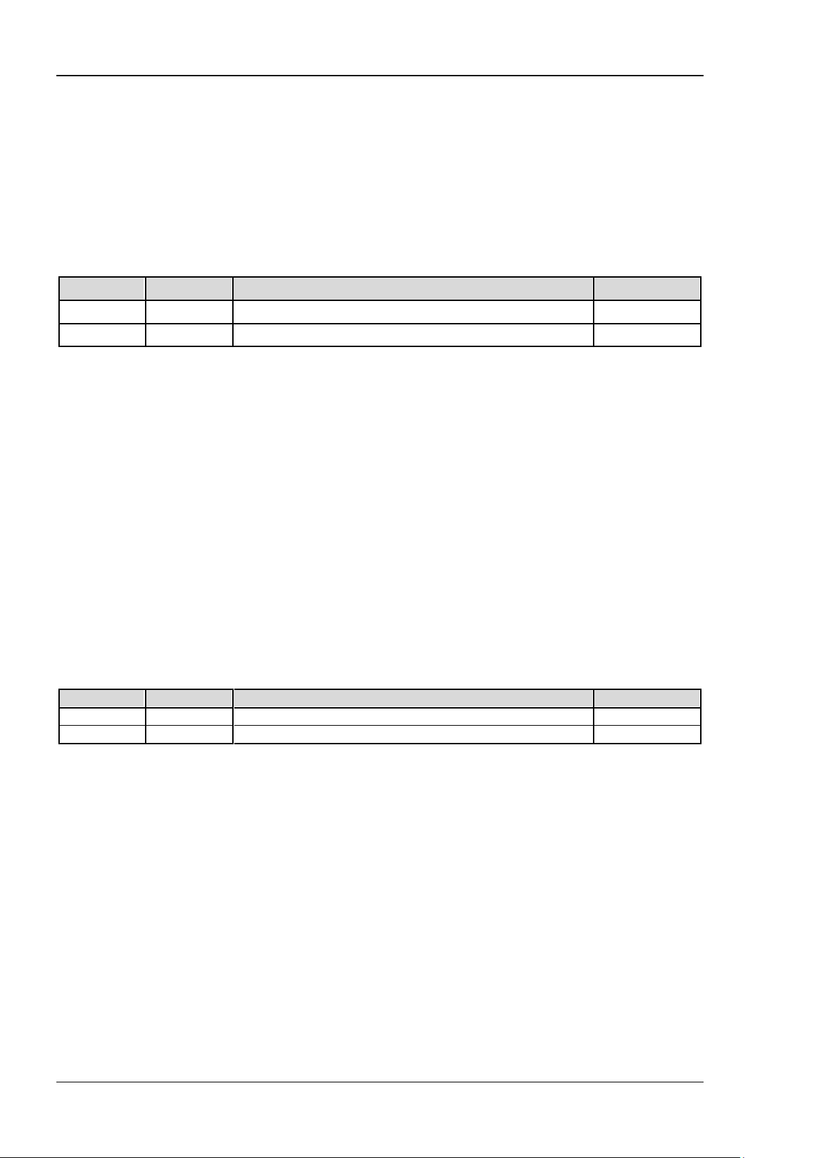
Parameter
Name Type Range Default
[1]
:
<bool> Bool {{1|ON}|{0|OFF}} 0|OFF
Return Format
The query returns 1 or 0.
:ACQuire:AVERages
Syntax
:ACQuire:AVERages <count>
:ACQuire:AVERages?
Description
Sets or queries the number of averages in the average acquisition mode (refer to the :ACQuire:TYPE
command).
Parameter
Remarks
In the average acquisition mode, the oscilloscope will acquire the waveform samples for several times, then
make an average o n th e w av ef o rms, so as to lo wer th e ran dom no is es of th e inpu t sign als and incr ease its
vertical resolution. Greater number of averages can lower the noises and increase the vertical resolution,
but will also slow the response of the displayed waveform to the waveform changes.
Return Format
The query returns a n integer.
<count> Integer 2n (n indicates an integer between 1 and 13). 2
2-4 DS4000E Programming Guide
Page 17

Chapter 2 Command System RIGOL
:ACQuire:MDEPth
Syntax
:ACQuire:MDEPth <mdep>
:ACQuire:MDEPth?
Description
Sets or queries the memory depth of the oscilloscope (namely the number of waveform points th at can be
stored through sampling in a single trigger). The default unit is pts (points).
Parameter
Remarks
The formula below describes the relationship among memory depth, sample rate, and waveform length:
Wherein, waveform length = horizontal time base x number of grids in the horiz ontal direction on t he
screen. For DS4000E, the number of grids in the horizontal direction on the screen is a fixed value 14. When
<mdep> is set to "AUTO", the oscilloscope will select the memory depth automatically according to the
current sample rate and horizontal time base (refer to the :TIMebase[:MAIN]:SCALe command).
Return Format
The query returns a n integer.
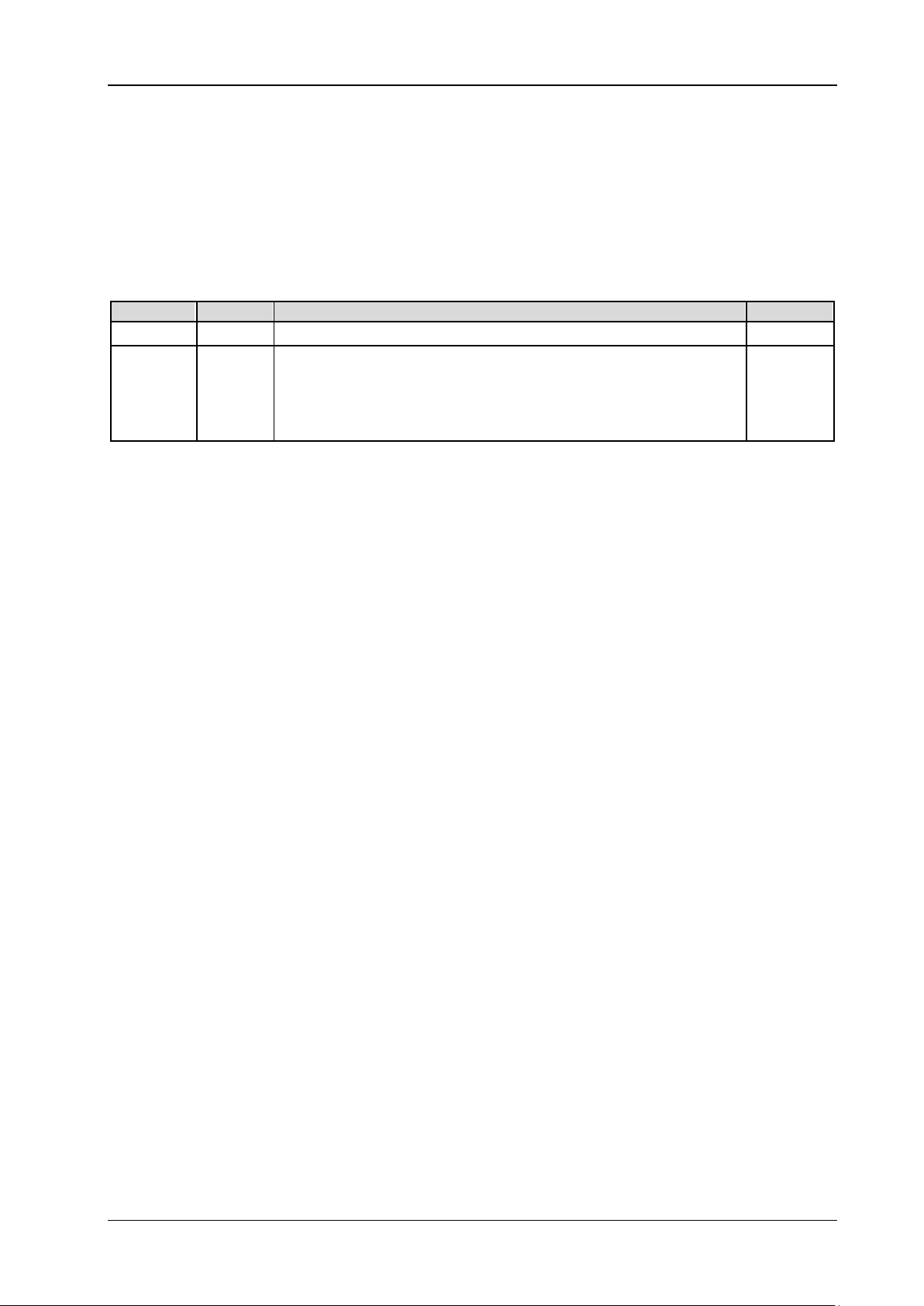
Name
<mdep> Discrete AUTO|7000|70000|700000|7000000 AUTO
Type Range Default
memory depth = sample rate x waveform length
:ACQuire:SRATe?
Syntax
:ACQuire:SRATe?
Description
Queries the current sample rate of the oscilloscope. The default unit is Sa/s.
Return Format
The query returns the sample rate in s cientific notation.
:ACQuire:TYPE
Syntax
:ACQuire:TYPE <type>
:ACQuire:TYPE?
Description
Sets or queries the data acquisition mode of the oscilloscope.
Parameter
Remarks
NORMa l: In this mode, the oscilloscope samples the signal at the same interval to reconstruct the
AVERages: In this mode, the oscilloscope will acquire the waveform samples for several times, then
DS4000E Programming Guide 2-5
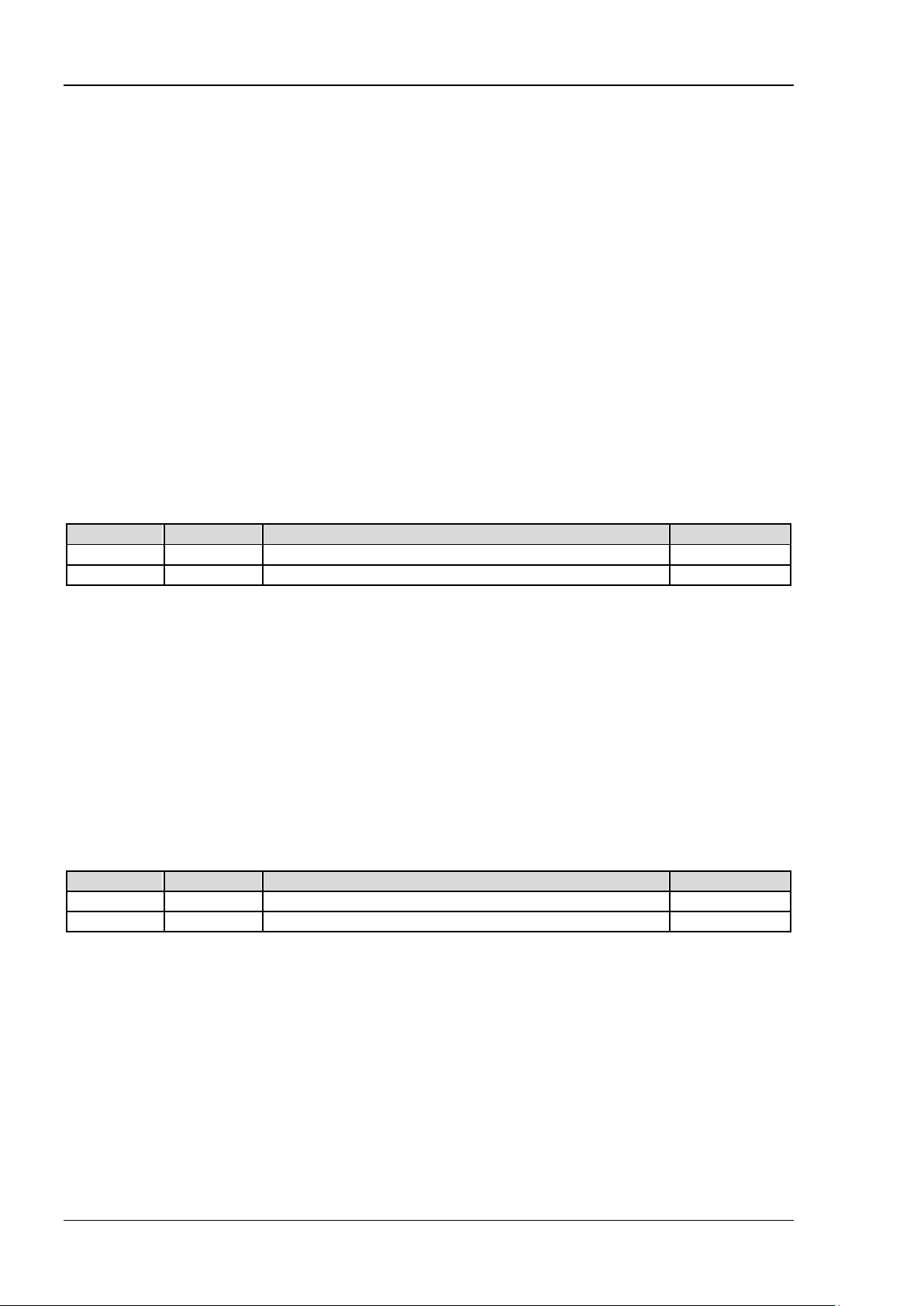
Name Type Range Default
<type> Discrete {NORMal|AVERages|PEAK|HRESolution} NORMal
waveform. For most of the waveforms, this mode can realize the best display effects.
Page 18

RIGOL Chapter 2 Command System
make an average on the waveforms, so as to lower the random noises of the input signals and increase
its vertical resolution. You can use the :ACQuire:AVERages command to set the number of av erages in
this mode.
PEAK: The oscilloscope samples the maximum and minimum value of the signal at the fixed sampling
interval to acquire the signal envelope or the narrow pulses that might be lost. This mode can avoid the
signal aliasing, but produces greater noises.
HRE Solution: The oscilloscope will average the adjacent sample points of the sample waveform to
lower the random noises of the input signals and display much more smoother waveforms. If the
sample rate of the digital convertor is greater than the storage rate of the acquisition memory, this
mode is often adopted.
Return Format
The query returns NORM, AVER, PEAK, or HRES.
2-6 DS4000E Programming Guide
Page 19

Chapter 2 Command System RIGOL
Name
Type
Range
Default
<n>
Discrete
{1|2}
--
:BUS<n> Commands
Command List:
:BUS<n>:DATA?
:BUS<n>:DISPlay
:BUS<n>:EEXPort
:BUS<n>:EVENt
:BUS<n>:FORMat
:BUS<n>:MODE
:BUS<n>:CAN (Option)
:BUS<n>:FLEXray (Opti on)
:BUS<n>:IIC (Option)
:BUS<n>:PARallel
:BUS<n>:RS232 (Option)
:BUS<n>:SPI (Option)
:BUS<n>:DATA?
Syntax
:BUS<n>:DATA?
Description
Reads the data in the decoding event table.
Parameter
Return Format
Returns the data in the decoding event table with the following formats.
#9000000077Parallel
Time,Data,
-9.3508796E-04,1,
6.5072008E-05,1,
1.0636000E-03,1,
Wherein, "#9000000077" is t he TMC data block header, which is followed by the data in the event table.
The 9-digit data following #9 in the data block header indicates the number of bytes of the effective data.
"Parallel" indicates the decoding type. The available decoding type can also be RS232, I2C, SPI, CAN, or
Flex. The data are separated by colons, and will automatically switch to the next line according to the line
length limit in the decoding list. The data value is related to the set numeral system.
Note: You can save all the data except TMC data block header (#9) and decoding type (Parallel)
"*.csv" file and view the data in the form of a list.
as the
DS4000E Programming Guide 2-7
Page 20
RIGOL Chapter 2 Command System
:BUS<n>:DISPlay
Syntax
:BUS<n>:DISPlay <bool>
:BUS<n>:DISPlay?
Description
Enables or disables the display of the specified decoding bus; or queries the on/off display status of the
specified decoding bus.
Parameter
Return Format
The query returns 1 or 0.
Name Type Range Default
<n> Discrete {1|2} -<bool> Bool {{1|ON}|{0|OFF}} 0|OFF
:BUS<n>:EEXPort
Name
Type Range Default
Syntax
:BUS<n>:EEXPort
Description
Exports the decoding information in the specified decoding bus event table to the external USB storage
device (if detected) in CSV form.
Parameter
<n> Discrete {1|2} --
:BUS<n>:EVENt
Syntax
:BUS<n>:EVENt <bool>
:BUS<n>:EVENt?
Description
Enables or disables the event table of the specified decoding bus; or queries the on/off status of the
specified decoding bus event table.
Parameter
Remarks
Before using the command, enable the display of the specified decodi ng bus (refer to the :BUS<n>:DISPlay
command).
Return Format
The query returns 1 or 0.
Name Type Range Default
<n> Discrete {1|2} -<bool> Bool {{1|ON}|{0|OFF}} 0|OFF
2-8 DS4000E Programming Guide
Page 21
Chapter 2 Command System RIGOL
:BUS<n>:FORMat
Syntax
:BUS<n>:FORMat <form at>
:BUS<n>:FORMat?
Description
Sets or queries the display format of decoding data of the specified decoding bus.
Parameter
Name
<n> Discrete {1|2} -<format> Discrete {HEX|DEC|BIN|ASCii} HEX
Return Format
The query returns HEX, DEC, BIN, or ASC.
Type Range Default
:BUS<n>:MODE
Syntax
:BUS<n>:MODE <mod e>
:BUS<n>:MODE?
Description
Sets or queries the decoding type of the specified decoding bus.
Parameter
Remarks
RS232 decoding, IIC decoding, SPI decoding, CAN decoding, and FlexRay decoding are optional functions.
This command can be used only when you have installed these options.
Return Format
The query returns PAR, RS232, IIC, SPI, CAN, or FLEX.
Name
<n> Discrete {1|2} -<mode> Discrete {PARallel|RS232|IIC|SPI|CAN|FLEXray} PARallel
Type Range Default
DS4000E Programming Guide 2-9
Page 22
RIGOL Chapter 2 Command System
<baud>
Discrete
{100000|125000|250000|400000|500000|800000|1000000|USER}
500000
:BUS<n>:CAN (Opti o n )
Command List:
:BUS<n>:CAN:BAUD
:BUS<n>:CAN:BUSer
:BUS<n>:CAN:OFFSet
:BUS<n>:CAN:SOURce
:BUS<n>:CAN:SPOint
:BUS<n>:CAN:STYPe
:BUS<n>:CAN:THReshold
:BUS<n>:CAN:BAUD
Syntax
:BUS<n>:CA N:BAUD <baud>
:BUS<n>:CAN:BAUD?
Description
Sets or queries the signal rate of CAN decoding on the specified bus. The default unit is b/s.
Parameter
Name
<n> Discrete {1|2} --
Type Range Default
Remarks
When <baud> is set to "U S E R ", you can use the :BUS<n>:CAN:BUSer command to self-define the signal
rate of CAN decoding on the specified bus.
Return Format
The query returns 100000, 125000, 250000, 400000, 500000, 800000, 1000000, or USER.
:BUS<n>:CAN:BUSer
Syntax
:BUS<n>:CA N:B USe r <ba u d>
:BUS<n>:CAN:BUSer?
Description
Sets or queries the user-defined signal rate of CAN decoding on the specified bus. The default unit is b/s.
Parameter
Return Format
The query returns an integer between 10000 and 1000000.
Name
<n> Discrete {1|2} -<baud> Integer 10000 to 1000000 500000
Type Range Default
2-10 DS4000E Programming Guide
Page 23
Chapter 2 Command System RIGOL
:BUS<n>:CAN:OFFSet
Syntax
:BUS<n>:CAN:OFFSet <val>
:BUS<n>:CAN:OFFSet?
Description
Sets or queries the vertical position of CAN decoding data line on the specified bus.
Parameter
Remarks
Before using the command, enable the display of the specified decoding bus (refer to
The range of <val> is related to the screen display mode and the on/off status of the statistic function
When the data line that displays the decoding is located in the middle part of the screen, <val > is 0;
Return Format
The query returns a n integer.
Name
<n> Discrete {1|2} -<val> Integer Refer to Remarks 0
the :BUS<n>:DISPlay command).
(refer to the :MEASure:STATistic:DISPlay command).
When the display mode is "Full Screen" and the statistics function is disabled, the <val> parameter
ranges from -166 to +148.
When the display mode is "Full Screen" and the statistics function is enabled, the <val> parameter
ranges from -163 to +143.
When the display mode is "Split" (refer to the :TIMebase:DELay:ENABle and :CALCulate:FFT:SPLit
command), the <val> parameter ranges from -103 to +52.
when it is located above the middle part of the screen, <val> is a positive value; when it is located
below the middle part of the screen, <val> is a negative value.
Type Range Default
:BUS<n>:CAN:SOURce
Syntax
:BUS<n>:CAN:SO UR ce <s ourc e >
:BUS<n>:CAN:SOURce?
Description
Sets or queries the source channel of CAN decoding on the specified bus.
Parameter
Name
<n> Discrete {1|2} -<source> Discrete {CHANnel1|CHANnel2|CHANnel3|CHANnel4} CHANnel1
Type Range Default
Return Format
The query returns CHAN1, CHAN2, CHAN3, or CHAN4.
DS4000E Programming Guide 2-11
Page 24
RIGOL Chapter 2 Command System
Name
Type
Range
Default
<stype>
Discrete
{RX|TX|CANH|CANL|DIFFerential}
RX
:BUS<n>:CAN:SPOint
Syntax
:BUS<n>:CAN:SPOint <spo>
:BUS<n>:CAN:SPOint?
Description
Sets or queries the sample point position of CAN decoding on the specified bus (expressed in %).
Parameter
Name
<n> Discrete {1|2} -<spo> Integer 5 to 95 50
Remarks
The sample point is within the range of the bit time. The oscilloscope samples the bit level at the sample
point. The sample point position is expressed as the ratio of "time from the bit start to the sample point" to
"bit time", in %.
Return Format
The query returns an integer between 5 and 95.
Type Range Default
:BUS<n>:CAN:STYPe
Syntax
:BUS<n>:CAN:S TYPe <stype>
:BUS<n>:CAN:STYPe?
Description
Sets or queries the signal type of CAN decoding on the specified bus.
Parameter
<n> Discrete {1|2} --
Remarks
RX: indicates the Receive signal from the CAN bus transceiver.
TX: indicates the Transmit signal from the CAN bus transceiver.
CANH: indicates the actual CAN_H differential bus signal.
CANL: indicates the actual CAN_L differential bus signal.
DIFFerential: indicates the CAN differential bus signal connected to an analog channel by using a
differential probe. The positive polarity of the differential probe connects the CAN_H bus signal, a nd
the negative polarity connects the CAN_L bus signal.
Return Format
The query returns RX, TX, CANH, CANL, or DIFF.
2-12 DS4000E Programming Guide
Page 25
Chapter 2 Command System RIGOL
Name
Type
Range
Default
--
:BUS<n>:CAN:THReshold
Syntax
:BUS<n>:CAN:THR eshold <thre>
:BUS<n>:CAN:THReshold?
Description
Sets or queries the threshold of the current source channel of CAN decoding on the specified bus.
Parameter
<n> Discrete {1|2}
(-4 x VerticalScale - Offset) to (4 x VerticalScale - Offset)
Wherein, VerticalScale is the vertical scale of the source channel,
<thre> Real
Return Format
The query returns the threshold level in scientific notation.
refer to the :CHANnel<n>:SCALe command; Offset is the vertical
position of the source channel, refer to t he :CHANnel<n>:OFFSet
command.
0
DS4000E Programming Guide 2-13
Page 26
RIGOL Chapter 2 Command System
Name
Type
Range
Default
Remarks
:BUS<n>:FLEXray (Option)
Command List:
:BUS<n>:FLEXray:BAUD
:BUS<n>:FLEXray:OFFSet
:BUS<n>:FLEXray:SOURce
:BUS<n>:FLEXray:SPoint
:BUS<n>:FLEXray:STYPe
:BUS<n>:FLEXray:THReshold
:BUS<n>:FLEXray:BAUD
Syntax
:BUS<n>:FLEXray:BAUD <baud>
:BUS<n>:FLEXray:BAUD?
Description
Sets or queries the signal rate of FlexRay decoding on the specified bus. The default unit is b/s.
Parameter
Return Format
The query returns 2500000, 5000000, or 10000000.
:BUS<n>:FLEXray:OFFSet
Syntax
:BUS<n>:FLEXra y :OF F Set <val>
:BUS<n>:FLEXray:OFFSet?
Description
Sets or queries the vertical position of FlexRay decoding on the specified bus.
Parameter
Remarks
Before using the command, enable the display of the specified decoding bus (refer to
The range of <val> is related to the screen display mode and the on/off status of the statistic function
When the data line that displays the decoding is located in the middle part of the screen, <val > is 0;
Name
<n> Discrete {1|2} -<baud> Discrete {2500000|5000000|10000000} 10000000
Type Range Default
<n> Discrete {1|2} -<val> Integer Refer to
the :BUS<n>:DISPlay command).
(refer to the :MEASure:STATistic:DISPlay command).
When the display mode is "Full Screen" and the statistics function is disabled, the <val> parameter
ranges from -166 to +148.
When the display mode is "Full Screen" and the statistics function is enabled, the <val> parameter
ranges from -163 to +143.
When the display mode is "Split" (refer to the :TIMebase:DELay:ENABle and :CALCulate:FFT:SPLit
command), the <val> parameter ranges from -103 to +52.
when it is located above the middle part of the screen, <val> is a positive value; when it is located
0
2-14 DS4000E Programming Guide
Page 27
Chapter 2 Command System RIGOL
Name
Type
Range
Default
below the middle part of the screen, <val> is a negative value.
Return Format
The query returns a n integer.
:BUS<n>:FLEXray:SOURce
Syntax
:BUS<n>:FLEXra y :SO UR ce <source>
:BUS<n>:FLEXray:SOURce?
Description
Sets or queries the source channel of FlexRay decoding on the specified bus.
Parameter
Return Format
The query returns CHAN1, CHAN2, CHAN3, or CHAN4.
<n> Discrete {1|2} -<source> Discrete {CHANnel1|CHANnel2|CHANnel3|CHANnel4} CHANnel1
:BUS<n>:FLEXray:SPoint
Syntax
:BUS<n>:FLEXray:SPoint <spo>
:BUS<n>:FLEXray:SPoint?
Description
Sets or queries the sample point position of FlexRa y decoding on the specified bus (expressed in %).
Parameter
Remarks
The sample point is within the range of the bit time. The oscilloscope samples the bit level at the sample
point. The sample point position is expressed as the ratio of "time from the bit start to the sample poi nt" to
"bit time", in %.
Return Format
The query returns an integer between 5 and 95.
Name
<n> Discrete {1|2} -<spo> Integer 5 to 95 50
Type Range Default
:BUS<n>:FLEXray:STYPe
Syntax
:BUS<n>:FLEXray:STYPe <type>
:BUS<n>:FLEXray:STYPe?
Description
Sets or queries the signal type of FlexRay decoding on the specified bus.
DS4000E Programming Guide 2-15
Page 28
RIGOL Chapter 2 Command System
Name
Type
Range
Default
<n>
Discrete
{1|2}
--
<type>
Discrete
{BP|BM|RT}
BP
Name
Type
Range
Default
(-4 x VerticalScale - Offset) to (4 x VerticalScale - Offset)
Parameter
Return Format
The query returns BP, BM, or RT.
:BUS<n>:FLEXray:THReshold
Syntax
:BUS<n>:FLEXray:THReshold <thre>
:BUS<n>:FLEXray:THReshold?
Description
Sets or queries the threshold of the current source channel of FlexRay decoding on the speci fi ed bus.
Parameter
<n> Discrete {1|2}
--
Wherein, VerticalScale is the vertical scale of the source
<thre> Real
Return Format
The query returns the threshold level in scientific notation.
channel, refer to the :CHANnel<n>:SCALe command;
Offset is the vertical position of the source channel, refer
to the :CHANnel<n>:OFFSet command.
0
2-16 DS4000E Programming Guide
Page 29
Chapter 2 Command System RIGOL
:BUS<n>:IIC (Option)
Command List:
:BUS<n>:IIC:OFFSet
:BUS<n>:IIC:SCLK:SOURce
:BUS<n>:IIC:SCLK:THReshold
:BUS<n>:IIC:SDA:SOURce
:BUS<n>:IIC:SDA:THReshold
:BUS<n>:IIC:OFFSet
Syntax
:BUS<n>:IIC:OFF Set <val>
:BUS<n>:IIC:OFFSet?
Description
Sets or queries the vertical position of IIC decoding on the specified bus.
Parameter
Name Type Range Default
<n> Discrete {1|2} -<val> Integer Refer to Remarks 0
Remarks
Before using the command, enable the display of the specified decoding bus (refer to
the :BUS<n>:DISPlay command).
The range of <val> is related to the screen display mode and the on/off status of the statistic function
(refer to the :MEASure:STATistic:DISPlay command).
When the display mode is "Full Screen" and the statistics function is disabled, the <val> parameter
ranges from -166 to +148.
When the display mode is "Full Screen" and the statistics function is enabled, the <val> parameter
ranges from -163 to +143.
When the display mode is "Split" (refer to the :TIMebase:DELay:ENABle and :CALCulate:FFT:SPLit
command), the <val> parameter ranges from -103 to +52.
When the data line that displays the decoding is located in the middle part of the screen, <val > is 0;
when it is located above the middle part of the screen, <val> is a positive value; when it is located
below the middle part of the screen, <val> is a negative value.
Return Format
The query returns a n integer.
:BUS<n>:IIC:SCLK:SOURce
Syntax
:BUS<n>:IIC:SCLK:SOURce <source>
:BUS<n>:IIC:SCLK:SOURce?
Description
Sets or queries the source channel of the clock line of IIC decoding on the specified bus.
DS4000E Programming Guide 2-17
Page 30
RIGOL Chapter 2 Command System
Name
Type
Range
Default
<n>
Discrete
{1|2}
--
<source>
Discrete
{CHANnel1|CHANnel2|CHANnel3|CHANnel4}
CHANnel1
(-4 x VerticalScale - Offset) to (4 x VerticalScale - Offset)
Name
Type
Range
Default
<n>
Discrete
{1|2}
--
Parameter
Return Format
The query returns CHAN1, CHAN2, CHAN3, or CHAN4.
:BUS<n>:IIC:SCLK:THReshold
Syntax
:BUS<n>:IIC:SCLK:THReshold <thre>
:BUS<n>:IIC:SCLK:THReshold?
Description
Sets or queries the threshold of the current clock line source channel of IIC decoding on the specified bus.
The default unit is V.
Parameter
Name Type Range Default
<n> Discrete {1|2}
--
Wherein, VerticalScale is the vertical scale of the clock line source
<thre> Real
Return Format
The query returns the threshold level in scientific notation.
channel, refer to the :CHANnel<n>:SCALe command; Offset is the
vertical position of the clock line source channel, refer to
the :CHANnel<n>:OFFSet command.
0
:BUS<n>:IIC:SDA:SOURce
Syntax
:BUS<n>:IIC:S DA :SO UR ce <s o urce>
:BUS<n>:IIC:SDA:SOURce?
Description
Sets or queries the source channel of the data line of IIC decoding on the specified bus.
Parameter
Return Format
The query returns CHAN1, CHAN2, CHAN3, or CHAN4.
<source> Discrete {CHANnel1|CHANnel2|CHANnel3|CHANnel4} CHANnel2
2-18 DS4000E Programming Guide
Page 31

Chapter 2 Command System RIGOL
Name
Type
Range
Default
--
:BUS<n>:IIC:SDA:THReshold
Syntax
:BUS<n>:IIC:SDA:THReshold <thre>
:BUS<n>:IIC:SDA:THReshold?
Description
Sets or queries the threshold of the current data line source channel of IIC decoding on the specified bus.
Parameter
<n> Discrete {1|2}
(-4 x VerticalScale - Offset) to (4 x VerticalScale - Offset)
Wherein, VerticalScale is the vertical scale of the data line source
<thre> Real
Return Format
The query returns the threshold level in scientific notation.
channel, refer to the :CHANnel<n>:SCALe command; Offset is the
vertical position of the data line source channel, refer to
the :CHANnel<n>:OFFSet command.
0
DS4000E Programming Guide 2-19
Page 32

RIGOL Chapter 2 Command System
<n>
Discrete
{1|2}
--
<b0>
Discrete
{CHANnel1|CHANnel2|CHANnel3|CHANnel4}
CHANnel1
<b1>
Discrete
{CHANnel1|CHANnel2|CHANnel3|CHANnel4}
CHANnel1
<b2>
Discrete
{CHANnel1|CHANnel2|CHANnel3|CHANnel4}
CHANnel1
<b3>
Discrete
{CHANnel1|CHANnel2|CHANnel3|CHANnel4}
CHANnel1
Name
Type
Range
Default
--
:BUS<n>:PARallel
Command List:
:BUS<n>:PARallel:BSET
:BUS<n>:PARallel:CLK
:BUS<n>:PARallel:OFFSet
:BUS<n>:PARallel:SLOPe
:BUS<n>:PARallel:THReshold
:BUS<n>:PARallel:BSET
Syntax
:BUS<n>:PARallel:BSET <b0>[,<b1>[,<b2>[,<b3>]]]
:BUS<n>:PARallel:BSET?
Description
Sets or queries the source channel of each bit of the data line of Parallel decoding on specified bus; or
queries the data line source channel of Parallel decoding on the specified bus.
Parameter
Name
Type Range Default
Remarks
This com ma nd als o sets the bit width (ranges from 1 to 4 and equals to the number of the specified
channel sources) of Parallel decoding.
The bit order is LSB first.
Return Format
The query returns the channel source of each bit (with the LSB-first bit order) of the current data line. The
channel sources are separated by commas.
:BUS<n>:PARallel:CLK
Syntax
:BUS<n>:PARa lle l:CLK <so ur ce>
:BUS<n>:PARallel:CLK?
Description
Sets or queries the source channel of the clock line of Parallel decoding on the specified bus.
Parameter
<n> Discrete {1|2}
<source> Discrete {CHANnel1|CHANnel2|CHANnel3|CHANnel4|OFF} CHANnel1
2-20 DS4000E Programming Guide
Page 33

Chapter 2 Command System RIGOL
Name
Type
Range
Default
Remarks
You can send the :BUS<n>:PARallel:SLOPe command to sample data channel's data on the rising edge,
falling edge, or either of the edges of the clock signal. When <sour ce> is set to "OFF" (disabling the clock
channel), sampling is performed whe n a hop occurs to the data of the data channel during decoding.
Return Format
The query returns CHAN1, CHAN2, CHAN3, CHAN4, or OFF.
:BUS<n>:PARallel:OFFSet
Syntax
:BUS<n>:PARa lle l:O F FSet <val>
:BUS<n>:PARallel:OFFSet?
Description
Sets or queries the vertical position of Parallel decoding on the specified bus.
Parameter
Remarks
Before using the command, enable the display of the specified decoding bus (refer to
The range of <val> is related to the screen display mode and the on/off status of the statistic function
When the data line that displays the decoding is located in the middle part of the screen, <val> is 0;
Return Format
The query returns an integer.
Name Type Range Default
<n> Discrete {1|2} -<val> Integer Refer to Remarks 0
the :BUS<n>:DISPlay command).
(refer to the :MEASure:STATistic:DISPlay command).
When the display mode is "Full Screen" and the statistics function is disabled, the <val> parameter
ranges from -166 to +148.
When the display mode is "Full Screen" and the statistics function is enabled, the <val> parameter
ranges from -163 to +143.
When the display mode is "Split" (refer to the :TIMebase:DELay:ENABle and :CALCulate:FFT:SPLit
command), the <val> parameter ranges from -103 to +52.
when it is located above the middle part of the screen, <val> is a positive value; when it is located
below the middle part of the screen, <val> is a negative value.
:BUS<n>:PARallel:SLOPe
Syntax
:BUS<n>:PARallel:SLOPe <slope>
:BUS<n>:PARallel:SLOPe?
Description
Sets or queries the edge type of the clock signal of Parallel decoding on the specified bus.
Parameter
<n> Discrete {1|2} -<slope> Discrete {POSitive|NEGative|BOTH} POSitive
DS4000E Programming Guide 2-21
Page 34

RIGOL Chapter 2 Command System
(-4 x VerticalScale - Offset) to (4 x VerticalScale - Offset)
Remarks
POSitive: samples the data of the data channel on the rising edge of the clock signal.
NEGative:
BOTH: samples the data of the data cha nnel on both the rising and falling edge of the clock signal.
If t he clock channel is currently not set (refer to the :BUS<n>:PARallel:CLK command), you do not
need to use the command to set the edge type.
Return Format
The query returns POS, NEG, or BOTH.
samples the data of the data channel on the falling edge of the clock signal.
:BUS<n>:PARallel:THReshold
Syntax
:BUS<n>:PARallel:THReshold <source>,<thre>
:BUS<n>:PARallel:THReshold? <source>
Description
Sets or queries the threshold level of the sp ecified analog channel of Parallel decoding on the specified bus.
Parameter
Name
<n> Discrete {1|2} -<source> Discrete {CHANnel1|CHANnel2|CHANnel3|CHANnel4} CHANnel1
Type Range Default
Wherein, VerticalScale is the vertical scale of the specified
<thre> Real
Return Format
The query returns the threshold level in scientific notation.
analog channel, refer to the :CHANnel<n>:SCALe command;
Offset is the vertical position of the specified analog channel,
refer to the :CHANnel<n>:OFFSet command.
0
2-22 DS4000E Programming Guide
Page 35

Chapter 2 Command System RIGOL
Name
Type
Range
Default
Name
Type
Range
Default
:BUS<n>:RS232 (Option)
Command List:
:BUS<n>:RS232:BAUD
:BUS<n>:RS232:BUSer
:BUS<n>:RS232:DBITs
:BUS<n>:RS232:ENDian
:BUS<n>:RS232:OFFSet
:BUS<n>:RS232:PACKet
:BUS<n>:RS232:PARity
:BUS<n>:RS232:PEND
:BUS<n>:RS232:POLarity
:BUS<n>:RS232:RTHReshold
:BUS<n>:RS232:RX
:BUS<n>:RS232:SBITs
:BUS<n>:RS232:TTHReshold
:BUS<n>:RS232:TX
:BUS<n>:RS232:BAUD
Syntax
:BUS<n>:RS232 :BAUD <baud>
:BUS<n>:RS232:BAUD?
Description
Sets or queries the baud rate of data of RS232 decoding on the specified bus. The default unit is bps.
Parameter
Remarks
When <baud> is set to "USER", you can use the :BUS<n>:RS232:BUSer command to self-define the signal
rate of RS232 decoding on the specified bus.
Return Format
The query returns a n integer or USER.
:BUS<n>:RS232:BUSer
Syntax
:BUS<n>:RS232 :B USe r <b a ud>
:BUS<n>:RS232:BUSer?
Description
Sets or queries the us er-defined baud rate of data of RS232 decoding on the specified bus. The default unit
is bps.
Parameter
<n> Discrete {1|2} -<baud> Discrete
{2400|4800|9600|19200|38400|57600|115200|
230400|460800|921600|1000000|USER}
9600
<n> Discrete {1|2} -<baud> Integer 11 to 20000000 9600
DS4000E Programming Guide 2-23
Page 36

RIGOL Chapter 2 Command System
Name
Type
Range
Default
Name
Type
Range
Default
<n>
Discrete
{1|2}
--
<endian>
Discrete
{LSB|MSB}
LSB
Return Format
The query returns a n integer.
:BUS<n>:RS232:DBITs
Syntax
:BUS<n>:RS232:DBITs <bits>
:BUS<n>:RS232:DBITs?
Description
Sets or queries the data width (namely the actual number of data bits for each frame of data) of RS232
decoding on the specified bus.
Parameter
Return Format
The query returns 5, 6, 7, 8, or 9.
<n> Discrete {1|2} -<bits> Discrete {5|6|7|8|9} 8
:BUS<n>:RS232:ENDian
Syntax
:BUS<n>:RS232:EN Dia n < endi an>
:BUS<n>:RS232:ENDian?
Description
Sets or queries the bit order of data of RS232 decoding on the specified bus.
Parameter
Remarks
LSB: Least Significant Bit. The transmission sequence shall be is in as ce nding order.
MSB: Most Significa nt Bit. The transmission sequence shall be is in descending order.
Return Format
The query returns LSB or MSB.
:BUS<n>:RS232:OFFSet
Syntax
:BUS<n>:RS232 :OF FSe t <va l>
:BUS<n>:RS232:OFFSet?
Description
Sets or queries the vertical position of TX and/or RX of RS232 decoding on the specified bus.
2-24 DS4000E Programming Guide
Page 37

Chapter 2 Command System RIGOL
Parameter
Name
<n> Discrete {1|2} -<val> Integer Refer to Remarks 0
Remarks
Before using the command, enable the display of the specified decoding bus (refer to
the :BUS<n>:DISPlay command).
The range of <val> is related to the screen display mode and the on/off status of the statistic function
(refer to the :MEASure:STATistic:DISPlay command).
When the display mode is "Full Screen" and the statistics function is disabled, the <val> parameter
ranges from -166 to +148.
When the display mode is "Full Screen" and the statistics function is enabled, the <val> parameter
ranges from -163 to +143.
When the display mode is "Split" (refer to the :TIMebase:DELay:ENABle and :CALCulate:FFT:SPLit
command), the <val> parameter ranges from -103 to +52.
When the data line that displays the decoding is located in the middle part of the screen, <val > is 0;
when it is located above the middle part of the screen, <val> is a positive value; when it is located
below the middle part of the screen, <val> is a negative value.
Return Format
The query returns a n integer.
Type Range Default
:BUS<n>:RS232:PACKet
Syntax
:BUS<n>:RS232:PACKet <bool>
:BUS<n>:RS232:PACKet?
Description
Enables or disables the packet display of data of RS232 decoding on the specified bus; or queries th e on/off
status of data packet display of RS232 decoding on the specified b us.
Parameter
Remarks
When the packet display is on, multiple data blocks will be combined based on the currently selected packet
end (refer to the :BUS<n>:RS232:PEND command).
Return Format
The query returns 1 or 0.
Name
<n> Discrete {1|2} -<bool> Bool {{1|ON}|{0|OFF}} 0|OFF
Type Range Default
:BUS<n>:RS232:PARity
Syntax
:BUS<n>:RS232 :PA Ri ty <p a r ity>
:BUS<n>:RS232:PARity?
Description
Sets or queries the parity mode of data of RS232 decoding on the specified bus.
DS4000E Programming Guide 2-25
Page 38

RIGOL Chapter 2 Command System
Name
Type
Range
Default
<n>
Discrete
{1|2}
--
<parity>
Discrete
{NONE|ODD|EVEN}
NONE
Name
Type
Range
Default
<n>
Discrete
{1|2}
--
Parameter
Remarks
None: indicates that there is no parity bit in data transmission.
ODD: indicates the odd parity bit. The total count of occurrences of 1 in the data bit and check bit is an
odd number. For example, if 0x55 (01010101) is transmitted, 1 shall be added to the check bit.
Even: indicates the even parity bit. The total count of occurrences of 1 in the data bit and check bit is
an even number. For example, if 0x55 (01010101) is transmitted, 0 shall be added to the check bit.
Return Format
The query returns NONE, ODD, or EVEN.
:BUS<n>:RS232:PEND
Syntax
:BUS<n>:RS232:PEND <package end>
:BUS<n>:RS232:PEND?
Description
Sets or queries the packet end of data of RS232 decoding on the specified bus.
Parameter
<package end> Discrete {NULL|LF|CR|SP|FF} NULL
Remarks
The parameters are represented in hexadecimal as follows:
When the packet display is on (refer to the :BUS<n>:RS232:PACKet command), multiple data blocks
Return Format
The query returns NULL, LF, CR, SP, or FF.
NULL: 00
LF: 0A
CR: 0D
SP: 20
FF: FF
will be combined based on the currently selected end of packet (EOP).
:BUS<n>:RS232:POLarity
Syntax
:BUS<n>:RS232 :PO La rit y <pol >
:BUS<n>:RS232:POLarity?
Description
Sets or queries the polarity of RS232 d ecoding on the specified bus.
2-26 DS4000E Programming Guide
Page 39

Chapter 2 Command System RIGOL
Name
Type
Range
Default
<n>
Discrete
{1|2}
--
<pol>
Discrete
{POSitive|NEGative}
NEGative
Name
Type
Range
Default
<n>
Discrete
{1|2}
--
(-4 x VerticalScale - Offset) to (4 x VerticalScale - Offset)
<n>
Discrete
{1|2}
--
<source>
Discrete
{CHANnel1|CHANnel2|CHANnel3|CHANnel4|OFF}
OFF
Parameter
Remarks
NEGative: Use negative logic. High level indicates logic "0"; low level indicates logic "1".
PO Sitive: U se positive logic. High level indicates logic "1"; low level indicates logic "0".
Return Format
The query returns POS or NEG.
:BUS<n>:RS232:RTHReshold
Syntax
:BUS<n>:RS232:RTHReshold <rthre>
:BUS<n>:RS232:RTHReshold?
Description
Sets or queries the threshold of RX source channel of RS232 decoding on the specified bus.
Parameter
Wherein, VerticalScale is the vertical scale of RX source
<rthre> Real
Return Format
The query returns the threshold level in scientific notation.
channel, refer to the :CHANnel<n>:SCALe command;
Offset is the vertical position of RX source channel, refer
to the :CHANnel<n>:OFFSet command.
0
:BUS<n>:RS232:RX
Syntax
:BUS<n>:RS232 :RX <so urce >
:BUS<n>:RS232:RX?
Description
Sets or queries RX source channel of RS232 decoding on the specified bus.
Parameter
Remarks
When <source> is set to "OFF", it indicates that no RX source channel will be set.
TX source channel (refer to the :BUS<n>:RS232:TX command) and RX source channel cannot be both
Return Format
The query returns CHAN1, CHAN2, CHAN3, CHAN4, or OFF.
Name
set to "OFF".
Type Range Default
DS4000E Programming Guide 2-27
Page 40

RIGOL Chapter 2 Command System
Name
Type
Range
Default
<n>
Discrete
{1|2}
--
(-4 x VerticalScale - Offset) to (4 x VerticalScale - Offset)
:BUS<n>:RS232:SBITs
Syntax
:BUS<n>:RS232:SBITs <stop bits>
:BUS<n>:RS232:SBITs?
Description
Sets or queries the number of stop bits following each frame of data of RS232 decoding on the specified
bus.
Parameter
Return Format
The query returns 1, 1.5, or 2.
<stop bits> Discrete {1|1.5|2} 1
:BUS<n>:RS232:TTHReshold
Syntax
:BUS<n>:RS232:TTHReshold <tthre>
:BUS<n>:RS232:TTHReshold?
Description
Sets or queries the threshold of TX source channel of RS232 de coding on the specified bus.
Parameter
Name
<n> Discrete {1|2} --
Type Range Default
Wherein, VerticalScale is the vertical scale of TX source
<tthre> Real
Return Format
The query returns the threshold level in scientific notation.
channel, refer to th e :CHANnel<n>:SCALe command; Offset is
the vertical position of TX source channel, refer to
the :CHANnel<n>:OFFSet command.
0
:BUS<n>:RS232:TX
Syntax
:BUS<n>:RS232 : TX <so urc e >
:BUS<n>:RS232:TX?
Description
Sets or queries TX source channel of RS232 decoding on the specified bus.
Parameter
Name
<n> Discrete {1|2} -<source> Discrete {CHANnel1|CHANnel2|CHANnel3|CHANnel4|OFF} CHANnel1
Type Range Default
2-28 DS4000E Programming Guide
Page 41

Chapter 2 Command System RIGOL
Remarks
Whe n <so urce > is set to "OFF", it indicates that TX source channel is not set.
TX source channel and RX source channel (refer to the :BUS<n>:RS232:RX command) cannot be both
set to "OFF".
Return Format
The query returns CHAN1, CHAN2, CHAN3, CHAN4, or OFF.
DS4000E Programming Guide 2-29
Page 42

RIGOL Chapter 2 Command System
<n>
Discrete
{1|2}
--
<endian>
Discrete
{MSB|LSB}
MSB
:BUS<n>:SPI (Opt ion)
Command List:
:BUS<n>:SPI:DBITs
:BUS<n>:SPI:ENDian
:BUS<n>:SPI:MISO:POLarity
:BUS<n>:SPI:MISO:SOURce
:BUS<n>:SPI:MISO:THReshold
:BUS<n>:SPI:MODE
:BUS<n>:SPI:MOSI:POLarity
:BUS<n>:SPI:MOSI:SOURce
:BUS<n>:SPI:MOSI:THReshold
:BUS<n>:SPI:OFFSet
:BUS<n>:SPI:SCLK:SLOPe
:BUS<n>:SPI:SCLK:SOURce
:BUS<n>:SPI:SCLK:THReshold
:BUS<n>:SPI:SS:POLarity
:BUS<n>:SPI:SS:SOURce
:BUS<n>:SPI:SS:THReshold
:BUS<n>:SPI:TIMeout:TIME
:BUS<n>:SPI:DBITs
Syntax
:BUS<n>:SPI:DBITs <width>
:BUS<n>:SPI:DBITs?
Description
Sets or queries the bus width of SPI decoding on the specified bus.
Parameter
Name Type Range Default
<n> Discrete {1|2}
<width> Integer 4 to 32 8
Return Format
The query returns an integer between 4 and 32.
:BUS<n>:SPI:ENDian
Name
Type Range Default
Syntax
:BUS<n>:SPI:EN Dian <e nd ia n>
:BUS<n>:SPI:ENDian?
Description
Sets or queries the bit order of data transmission of SPI decoding on the specified bus.
Parameter
--
2-30 DS4000E Programming Guide
Page 43

Chapter 2 Command System RIGOL
Name
Type
Range
Default
Remarks
MSB: Most Significa nt Bit. The transmission sequence shall be is in descending order.
LSB: Least Significant Bit. The transmission sequence shall be is in as ce nding order.
Return Format
The query returns MSB or LSB.
:BUS<n>:SPI:MISO:POLarity
Syntax
:BUS<n>:SPI:MISO:POLarit y <pol>
:BUS<n>:SPI:MISO:POLarity?
Description
Sets or queries the polarity of MISO data line of SPI decoding on the specified bus.
Parameter
Name Type Range Default
<n> Discrete {1|2}
<pol> Discrete {HIGH|LOW} HIGH
Remarks
If t he source channel of MISO data line of SPI decoding on the specified bus is not set (refer to
the :BUS<n>:SPI:MISO:SOURce command), the :BUS<n>:SPI:MISO:POLarity <pol>command is
invalid.
LOW: indicates that low level is 1 and high level is 0.
HIGH: indicates that high level is 1 and low level is 0.
Return Format
The query returns HIGH or LOW.
--
:BUS<n>:SPI:MISO:SOURce
Syntax
:BUS<n>:SPI:MISO:SOURce <source>
:BUS<n>:SPI:MISO:SOURce?
Description
Sets or queries the source channel of MISO data line of SPI decoding on the sp ecified bus.
Parameter
Remarks
When <source> is se t to "OFF", it indicates that the source channel of MISO data line is not set.
If <source> is set to "CHANnel1", "CHANnel2", "CHANnel3", or "CHANnel4", you can use
The source channels of MISO data line and M OSI data line (refer to the :BUS<n>:SPI:MOSI:SOURce
<n> Discrete {1|2} -<source> Discrete {CHANnel1|CHANnel2|CHANnel3|CHANnel4|OFF} CHANnel2
the :BUS<n>:SPI:MISO:THReshold command to set the threshold of the source channel of MISO data
line.
command) cannot be both set to "OFF".
DS4000E Programming Guide 2-31
Page 44

RIGOL Chapter 2 Command System
Return Format
The query returns CHAN1, CHAN2, CHAN3, CHAN4, or OFF.
:BUS<n>:SPI:MISO:THReshold
Syntax
:BUS<n>:SPI:MI SO: THReshol d <thre >
:BUS<n>:SPI:MISO:THReshold?
Description
Sets or queries the threshold of the source channel of MISO data line of SPI decoding on the specified bus.
The default unit is V.
Parameter
Return Format
The query returns the threshold level in scientific notation.
Name
<n> Discrete {1|2} --
<thre> Real
Type Range Default
(-4 x VerticalScale - Offset) to (4 x VerticalScale - Offset)
Wherein, VerticalScale is the vertical scale of the MISO data
line source channel, refer to the :CHANnel<n>:SCALe
command; Offset is the vertical position of the MISO data line
source channel, refer to the :CHANnel<n>:OFFSet command.
0
:BUS<n>:SPI:MODE
Name
Type Range Default
Syntax
:BUS<n>:SPI:MODE <m od e >
:BUS<n>:SPI:MODE?
Description
Sets or queries the decode mode of SPI decoding on the specified bus.
Parameter
<n> Discrete {1|2}
<mode> Discrete {CS|TIMeout} TIMeout
Remarks
TIMeout: When the clock signal keeps in idle state for a specified time (greater than the time-out
CS: When the chip select signal is the specified level, the oscilloscope will sample the data of the
Return Format
The query returns CS or TIM.
2-32 DS4000E Programming Guide
period), the oscilloscope will sample the data of the source channel of data line on the specified edge
of the clock signal.
source channel of data line on the specified edge of the clock signal.
--
Page 45

Chapter 2 Command System RIGOL
Name
Type
Range
Default
:BUS<n>:SPI:MOSI:POLarity
Syntax
:BUS<n>:SPI:MOSI:POLarity <pol>
:BUS<n>:SPI:MOSI:POLarity?
Description
Sets or queries the polarity of MOSI data line of SPI decoding on the specified bus.
Parameter
Name Type Range Default
<n> Discrete {1|2}
<pol> Discrete {HIGH|LOW} HIGH
Remarks
If t he source channel of MOSI data line of SPI decoding on the specified bu s is not set (refer to
the :BUS<n>:SPI:MOSI:SOURce command), the :BUS<n>:SP I:MOSI:POLarity <p ol> command is
invalid.
LOW: indicates that low level is 1 and high level is 0.
HIGH: indicates that high level is 1 and low level is 0.
Return Format
The query returns HIGH or LOW.
--
:BUS<n>:SPI:MOSI:SOURce
Syntax
:BUS<n>:SPI:MOSI:SOURce <source>
:BUS<n>:SPI:MOSI:SOURce?
Description
Sets or queries the source channel of MOSI data line of SPI decoding on the specified bus.
Parameter
Remarks
When <source> is set to "OFF", i t indicates that the source channel of MOSI data line is not set.
If <source> is set to "CHANnel1", "CHANnel2", "CHANnel3", or "CHANnel4", you can use
The source channels of MISO data line (refer to the :BUS<n>:SPI:MISO:SOURce command) and MOSI
Return Format
The query returns CHAN1, CHAN2, CHAN3, CHAN4, or OFF.
<n> Discrete {1|2} -<source> Discrete {CHANnel1|CHANnel2|CHANnel3|CHANnel4|OFF} OFF
the :BUS<n>:SPI:MOSI:THReshold command to set the threshold of the source channel of MOSI data
line.
data line cannot be both set to "OFF".
DS4000E Programming Guide 2-33
Page 46

RIGOL Chapter 2 Command System
(-4 x VerticalScale - Offset) to (4 x VerticalScale - Offset)
<n>
Discrete
{1|2}
--
<val>
Integer
Refer to Remarks
0
:BUS<n>:SPI:MOSI:THReshold
Syntax
:BUS<n>:SPI:MOSI : THReshol d <thre >
:BUS<n>:SPI:MOSI:THReshold?
Description
Sets or queries the threshold of the source channel of MOSI data line of SPI decoding on the specified bus.
Parameter
Return Format
The query returns the threshold level in scientific notation.
Name
<n> Discrete {1|2} --
<thre> Real
Type Range Default
Wherein, VerticalScale is the vertical scale of the MOSI data
line source channel, refer to the :CHANnel<n>:SCALe
command; Offset is the vertical position of the MOSI data line
source channel, refer to the :CHANnel<n>:OFFSet command.
0
:BUS<n>:SPI:OFFSet
Name
Type Range Default
Syntax
:BUS<n>:SPI:OF FSet <val >
:BUS<n>:SPI:OFFSet?
Description
Sets or queries the vertical position of MISO and/or M OSI data line of SPI decoding on the specified bus.
Parameter
Remarks
Before using the command, enable the display of the specified decoding bus (refer to
the :BUS<n>:DISPlay command).
The range of <val> is related to the screen display mode and the on/off status of the statistic function
(refer to the :MEASure:STATistic:DISPlay command).
When the display mode is "Full Screen" and the statistics function is disabled, the <val> parameter
ranges from -166 to +148.
When the display mode is "Full Screen" and the statistics function is enabled, the <val> parameter
ranges from -163 to +143.
When the display mode is "Split" (refer to the :TIMebase:DELay:ENABle and :CALCulate:FFT:SPLit
command), the <val> parameter ranges from -103 to +52.
When the data line that displays the decoding is located in the middle part of the screen, <val > is 0;
when it is located above the middle part of the scre en, <val> is a positive value; when it is located
below the middle part of the screen, <val> is a negative value.
Return Format
The query returns a n integer.
2-34 DS4000E Programming Guide
Page 47

Chapter 2 Command System RIGOL
Name
Type
Range
Default
<n>
Discrete
{1|2}
--
<n>
Discrete
{1|2}
--
<source>
Discrete
{CHANnel1|CHANnel2|CHANnel3|CHANnel4}
CHANnel1
:BUS<n>:SPI:SCLK:SLOPe
Syntax
:BUS<n>:SPI:SCLK :SLOPe <slope>
:BUS<n>:SPI:SCLK:SLOPe?
Description
Sets or queries on which type of edges of the clock signal is sampling performed on the data of source
channel of data line of SPI decoding on the speci fie d bus .
Parameter
Remarks
POSitive: indicates the rising edge. NEGative: indicates the falling edge.
Return Format
The query returns POS or NEG.
<slope> Discrete {POSitive|NEGative} POSitive
:BUS<n>:SPI:SCLK:SOURce
Name
Type Range Default
Syntax
:BUS<n>:SPI:SCLK:SOURce <source>
:BUS<n>:SPI:SCLK:SOURce?
Description
Sets or queries the source channel of the clock line of SPI decoding on the specified bus.
Parameter
Return Format
The query returns CHAN1, CHAN2, CHAN3, or CHAN4.
:BUS<n>:SPI:SCLK:THReshold
Syntax
:BUS<n>:SPI:SCLK :THR e s hold <t hre>
:BUS<n>:SPI:SCLK:THReshold?
Description
Sets or queries the threshold of the clock channel of SPI decoding on the specified bus.
DS4000E Programming Guide 2-35
Page 48

RIGOL Chapter 2 Command System
Name
Type
Range
Default
<n>
Discrete
{1|2}
--
(-4 x VerticalScale - Offset) to (4 x VerticalScale - Offset)
Name
Type
Range
Default
Parameter
Wherein, VerticalScale is the vertical scale of the source
<thre> Real
Return Format
The query returns the threshold level in scientific notation.
channel, refer to the :CHANnel<n>:SCALe command;
Offset is the vertical position of the source channel, refer
to the :CHANnel<n>:OFFSet command.
0
:BUS<n>:SPI:SS:POLarity
Syntax
:BUS<n>:SPI:S S:P OLa ri t y <pol>
:BUS<n>:SPI:SS:POLarity?
Description
Sets or queries the polarity of CS line of SPI decoding on the specified bus.
Parameter
Name Type Range Default
<n> Discrete {1|2} -<pol> Discrete {HIGH|LOW} LOW
Remarks
HIGH: indicates that the oscilloscope samples data of the source channel of data line on the specified
edge of the clock signal when the CS signal is high level.
LOW: indicates that the oscilloscope samples data of the source channel of data line on the specified
edge of the clock signal when the CS signal is low level.
Return Format
The query returns HIGH or LOW.
:BUS<n>:SPI:SS:SOURce
Syntax
:BUS<n>:SPI:SS:SOUR ce <so ur ce>
:BUS<n>:SPI:SS:SOURce?
Description
Sets or queries the source channel of the CS line of SPI d ecoding on the specified bus.
Parameter
<n> Discrete {1|2} -<source> Discrete {CHANnel1|CHANnel2|CHANnel3|CHANnel4} CHANnel2
Return Format
The query returns CHAN1, CHAN2, CHAN3, or CHAN4.
2-36 DS4000E Programming Guide
Page 49

Chapter 2 Command System RIGOL
Name
Type
Range
Default
<n>
Discrete
{1|2}
--
(-4 x VerticalScale - Offset) to (4 x VerticalScale - Offset)
:BUS<n>:SPI:SS:THReshold
Syntax
:BUS<n>:SPI:SS:THReshold <thre>
:BUS<n>:SPI:SS:THReshold?
Description
Sets or queries the threshold of the source channel of the CS line of SPI decoding on the speci fi ed bus.
Parameter
Return Format
The query returns the threshold level in scientific notation.
<thre> Real
Wherein, VerticalScale is the vertical scale of the CS line
source channel, refer to the :CHANnel<n>:SCALe
command; Offset is the vertical position of the CS line
source channel, refer to the :CHANnel<n>:OFFSet
command.
0
:BUS<n>:SPI:TIMeout:TIME
Name
Type Range Default
Syntax
:BUS<n>:SPI:TIMeout:TIME <time>
:BUS<n>:SPI:TIMeout:TIME?
Description
Sets or queries the timeout value in the timeout decode mode of SPI decoding on the specified bus. The
default unit is s.
Parameter
<n> Discrete {1|2} -<time> Real 100 ns to 1 s 1 μs
Return Format
The query returns the timeout value i n scientific notation.
DS4000E Programming Guide 2-37
Page 50

RIGOL Chapter 2 Command System
:CALCulate Commands
Command List:
:CALCulate:MODE
:CALCulate:ADD
:CALCulate:ADVanced
:CALCulate:DIVision
:CALCulate:FFT
:CALCulate:LOGic
:CALCulate:MULTiply
:CALCulate:SUB
:CALCulate:MODE
Syntax
:CALCulate:MODE <mod>
:CALCulate:MODE?
Description
Sets or queries the type of math operation.
Parameter
Remarks
ADD: adds the waveform voltage value of Source A and that of Source B point by point, then displays
SUB : subtracts the waveform volta ge value of Source B from t hat of Source A p oint by point, then
MULTiply: multiplies the waveform voltage value of Source A by that of Source B point by point, then
DIV ision: divides the waveform volt age value of Source A b y that of Source B at e ach point, then
FF T: quickly performs Fourier transform on the wa veform of the source channel, t hen displays the
LOGi c: performs log ic operation on the logic level (1 or 0) of t he waveform of Source A and that of
ADVanced: performs advanced operation based on user-def ined operation formula, then displays the
OFF: disables the math operation function.
Return Format
The query returns ADD, SUB, MULT, DIV, FFT, LOG, ADV, or OFF.
Name
<mod> Discrete {ADD|SUB|MULTiply|DIVision|FFT|LOGic|ADVanced|OFF} OFF
Type Range Default
the results.
displays the results.
displays the results.
displays the results. When the waveform voltage value of Source B is 0, the result of the division is
treated as 0.
results.
Source B point by point, then displays the results.
results.
2-38 DS4000E Programming Guide
Page 51

Chapter 2 Command System RIGOL
:CALCulate:ADD
Command List:
:CALCulate:ADD:INVert :CALCulate:ADD:SA :CALCulate:ADD:SB :CALCulate:ADD:VOFFset :CALCulate:ADD:VSCale
:CALCulate:ADD:INVert
Syntax
:CALCulate:ADD:INVert <bool>
:CALCulate:ADD:INVert?
Description
Enables or disables the invert display of the waveform of addition operation; or queries the on/off status of
the invert display of the waveform of addition operation.
Parameter
Name Type Range Default
<bool> Bool {{1|ON}|{0|OFF}} 0|OFF
Remarks
1|ON: turns the waveform invert on. The waveform voltage values are inverted and then displayed.
0|OFF: turns the waveform invert off. The waveform is displayed normally.
Return Format
The query returns 1 or 0.
:CALCulate:ADD:SA
:CALCulate:ADD:SB
Syntax
:CALCulate:ADD :SA <so urc e >
:CALCulate:ADD:SA?
:CALCulate:ADD:SB <source>
:CALCulate:ADD:SB?
Description
Sets or queries the channel source of Source A or Source B in "add" operation.
Parameter
Name
<source> Discrete {CHANnel1|CHANnel2|CHANnel3|CHANnel4} CHANnel1
Return Format
The query returns CHAN1, CHAN2, CHAN3, or CHAN4.
Type Range Default
DS4000E Programming Guide 2-39
Page 52

RIGOL Chapter 2 Command System
Name
Type
Range
Default
(-40 x vertical s c ale of the addition operation waveform) to (40
<scale>
Real
Refer to Remarks
2 V/div
:CALCulate:ADD:VOFFset
Syntax
:CALCulate:ADD:VOFFset <offs>
:CALCulate:ADD:VOFFset?
Description
Sets or queries the vertical position of the addition operation waveform. The unit is related to the current
amplitude unit of the source channel.
Parameter
<offs> Real
Return Format
The query returns the vertical position in scientific notation.
x vertical scale of the addition operation waveform)
0
:CALCulate:ADD:VSCale
Name
Type Range Default
Syntax
:CALCulate:ADD:V SCa le <s ca le >
:CALCulate:ADD:VSCale?
Description
Sets or queries the vertical scale of the addition operation waveform. The unit is related to the current
amplitude unit of the source channel.
Parameter
Remarks
The default range of <scale> is from 0.02 V/div to 500 V/div. Its actual range is related to the vertical scale
of the source channel (refer to the :CHANnel<n>:SCALe command), at 1-2-5 step.
Note: After the vertical scale of the source channel is modified, the range of <scale> will not be changed
until the addition operation is re-enabled.
Return Format
The query returns the vertical scale in scientific notation.
2-40 DS4000E Programming Guide
Page 53

Chapter 2 Command System RIGOL
<str>
ASCII String
Refer to Remarks
CH1+CH2
:CALCulate:ADVanced
Command List:
:CALCulate:ADVanced:EXPRession
:CALCulate:ADVanced:INVert
:CALCulate:ADVanced:VARiable1
:CALCulate:ADVanced:VARiable2
:CALCulate:ADVanced:VOFFset
:CALCulate:ADVanced:VSCale
:CALCulate:ADVanced:EXPRession
Name
Type Range Default
Syntax
:CALCulate:ADVanced:EXPRession <str>
:CALCulate:ADVanced:EXPRession?
Description
Sets or queries the expression of advanced operation.
Parameter
Remarks
Please enter legal expression by using the characters shown in the following figure.
Y ou can specify Variable1 (refer to the :CALCulate:ADVanced:VARiable1 command) and/or Variable2
Return Format
The query returns the expression of advanced operation in strings.
Note: The length of the expression is limited to 64 bytes.
(refer to the :CALCulate:ADVanced:VARiable2 command) in the expression.
:CALCulate:ADVanced:INVert
Syntax
:CALCulate:ADVanced:INVert <bool>
:CALCulate:ADVanced:INVert?
Description
Enables or disables the invert display of the advanced opera tion waveform; or queries the on/off status of
the invert display of the advanced operation waveform.
DS4000E Programming Guide 2-41
Page 54

RIGOL Chapter 2 Command System
Name
Type
Range
Default
<variable>
Real
Refer to Remarks
0
Name
Type
Range
Default
(-40 x vertical s c ale of the advanced operation waveform) to
Parameter
Name
<bool> Bool {{1|ON}|{0|OFF}} 0|OFF
Remarks
1|ON: turns the waveform invert on. The waveform voltage values are inverted and then displayed.
0|OFF: turns the waveform invert off. The waveform is displayed normally.
Return Format
The query returns 1 or 0.
Type Range Default
:CALCulate:ADVanced:VARiable1
:CALCulate:ADVanced:VARiable2
Syntax
:CALCulate:ADVanced:VARiable1 <variable>
:CALCulate:ADVanced:VARiable1?
:CALCulate:ADVanced:VARiable2 <variable>
:CALCulate:ADVanced:VARiable2?
Description
Sets or queries Variable1 or Variable2 in the expressio n of advanced operation.
Parameter
Remarks
<variable> is in the AeB format. Wherein, A is mantissa, and its available range is from -9.9999 to +9.9999
(with the minimum step of 0.0001, that is, precision to four decimals). B refers to the exponent with 10 as
the base, and its available value is an integer ranging from -9 to +9. In addition, <variable> can also be
expressed in decimal, and its available range is the same with that of the AeB format.
Return Format
The query returns Variable1 or Variable2 in scientific notation.
:CALCulate:ADVanced:VOFFset
Syntax
:CALCulate:ADVanced:VOFFset <offs>
:CALCulate:ADVanced:VOFFset?
Description
Sets or queries the vertical position of the advanced operation waveform. The unit is related to the
expression of advanced operation.
Parameter
<offs> Real
(40 x vertical scale of the advanced operation waveform)
0
2-42 DS4000E Programming Guide
Page 55

Chapter 2 Command System RIGOL
Remarks
The expression of advanced operation (refer to the :CALCulate:ADVanced:EXPRession command) may
contain CH1, CH2, CH3, or CH4.
Return Format
The query returns the vertical position in scientific notation.
:CALCulate:ADVanced:VSCale
Syntax
:CALCulate:ADVanced:VSCale <scale>
:CALCulate:ADVanced:VSCale?
Description
Sets or queries the vertical scale of the advanced operation waveform. The unit is related to the expression
of advanced operation.
Parameter
Remarks
The default range of <scale> is from 0.02 V/div to 500 V/div. Its actual range is related to the
If the e xpression of advanced operation contains C H1, CH2, CH3, or CH4, then, the a ctual range of
Return Format
The query returns the vertical scale in scientific notation.
Name
<scale> Real Refer to Remarks 2 V/div
expression of the advanced operation (refer to the :CALCulate:ADVanced:EXPRession command), at
1-2-5 step.
<scale> is related to the vertical scale of the specifi ed channel (refer to the :CHANnel<n>:SCALe
command).
For integration and differentiati on operations, the actual range of <scale> is related to the current
horizontal time base (refer to the :TIMebase[:MAIN]:SCALe command).
Note: After the vertical scale of the specif ied channel is mo dif ied, the range of <scale > will not be
changed until the advanced operation is re-enabled.
Type Range Default
DS4000E Programming Guide 2-43
Page 56

RIGOL Chapter 2 Command System
Name
Type
Range
Default
<source>
Discrete
{CHANnel1|CHANnel2|CHANnel3|CHANnel4}
CHANnel1
:CALCulate:DIVision
In the division operation, when the waveform voltage value of Source B is 0, the result of the division is
treated as 0.
Command List:
:CALCulate:DIVision:INVert :CALCulate:DIVision:SA :CALCulate:DIVision:SB :CALCulate:DIVision:VOFFset :CALCulate:DIVision:VSCale
:CALCulate:DIVision:INVert
Name
Type Range Default
Syntax
:CALCulate:DIVision:INVert <bool>
:CALCulate:DIVision:INVert?
Description
Enables or disables the invert display of the division operation waveform; or queries the on/off status of the
invert display of the division operation waveform.
Parameter
<bool> Bool {{1|ON}|{0|OFF}} 0|OFF
Remarks
1|ON: turns the waveform invert on. The waveform voltage values are inverted and then displayed.
0|OFF: turns the waveform invert off. The waveform is displayed normally.
Return Format
The query returns 1 or 0.
:CALCulate:DIVision:SA
:CALCulate:DIVision:SB
Syntax
:CALCulate:DIVision:SA <source>
:CALCulate:DIVision:SA?
:CALCulate:DIVision:SB <source>
:CALCulate:DIVision:SB?
Description
Sets or queries the channel source of Source A or Source B in division operation.
Parameter
Return Format
The query returns CHAN1, CHAN2, CHAN3, or CHAN4.
2-44 DS4000E Programming Guide
Page 57

Chapter 2 Command System RIGOL
Name
Type
Range
Default
(-40 x vertical scale of the division operation waveform) to (40 x
<scale>
Real
Refer to Remarks
2 U/div
:CALCulate:DIVision:VOFFset
Syntax
:CALCulate:DIVision:VOFFset <offs>
:CALCulate:DIVision:VOFFset?
Description
Sets or queries the vertical position of the division operation waveform. The unit is related to the current
amplitude unit of the source channel.
Parameter
<offs> Real
Return Format
The query returns the vertical position in scientific notation.
vertical scale of the division operation waveform)
0
:CALCulate:DIVision:VSCale
Name
Type Range Default
Syntax
:CALCulate:DIVision:VSCale <scale>
:CALCulate:DIVision:VSCale?
Description
Sets or queries the vertical scale of the division operation waveform. The unit is related to the current
amplitude unit of the source channel.
Parameter
Remarks
The default range of <scale> is from 20 nU/div to 100 MU/div. Its actual range is related to the vertical
scale of the source channel (refer to the :CHANnel<n>:SCALe command), at 1-2-5 step.
Note: After the vertical scale of the source channel is modified, the range of <scale> will not be changed
until the division operation is re-enabled.
Return Format
The query returns the vertical scale in scientific notation.
DS4000E Programming Guide 2-45
Page 58

RIGOL Chapter 2 Command System
Name
Type
Range
Default
<center>
Real
FFT horizontal position + 7 x FFT horizontal scale
8.750 MHz
:CALCulate:FFT
Command List:
:CALCulate:FFT:HCENter
:CALCulate:FFT:HOFFset
:CALCulate:FFT:HSCaLe
:CALCulate:FFT:HSPan
:CALCulate:FFT:SOURce
:CALCulate:FFT:SPLit
:CALCulate:FFT:VOFFset
:CALCulate:FFT:VSCale
:CALCulate:FFT:VSMode
:CALCulate:FFT:WINDow
:CALCulate:FFT:HCENter
Syntax
:CALCulate:FFT:HCENter <center>
:CALCulate:FFT:HCENter?
Description
Sets or queries the center frequency of FFT operation. The default unit is Hz.
Parameter
Return Format
The query returns the center frequency in scientific n otation.
:CALCulate:FFT:HOFFset
Syntax
:CALCulate:FFT:HOFFset <offs>
:CALCulate:FFT:HOFFset?
Description
Sets or queries the horizontal position of the FFT operation waveform. The default unit is Hz.
Parameter
Remarks
The range of <offs> is related to the on/off status of the anti-aliasing function, FFT sample rate (Sa),
FF T Sample Rate = Number of Pixels Per Grid Horizont ally/Horizontal Time Base
Name
<offs> Real Refer to Remarks 0
and FFT horizontal scale (Hspan). The relationship is shown as below:
When the anti-aliasing function is disabled, the range of <offs> is from (max{-0.5 x Sa, -14 x Hspan})
to (0.5 x Sa).
When the anti-aliasing function is enabled, the range of <offs> is from (max{-0.4 x Sa, -14 x Hspan})
to (0.4 x Sa).
Note: max{A, B} indicates selecting a greater value from A and B.
Wherein, Number of Pixels Per Grid Horizonta lly is related to the on/off status of FFT anti-aliasing
function. When the function is disabled, Number of Pixels Per Grid Horizontally is 50; when enabled, it
Type Range Default
2-46 DS4000E Programming Guide
Page 59

Chapter 2 Command System RIGOL
Name
Type
Range
Default
<span>
Real
Refer to Remarks
1.25 MHz/div
is 100. For the value of Horizontal Time Base, refer to the :TIMebase[:MAIN]:SCALe command.
The FFT horizontal s cale is related to the FFT sample rate and FFT horizontal coefficient, refer to
the :CALCulate:FFT:HSPan command.
Return Format
The query returns the horizontal position in scientific notation.
:CALCulate:FFT:HSCaLe
Syntax
:CALCulate:FFT:HSCale <hscale >
:CALCulate:FFT:HSCale?
Description
Sets or queries the horizontal coefficient of FFT operation.
Parameter
Remarks
This command indirectly sets the horizontal scale of FFT operation (refer to the :CALCulate:FFT:HSPan
FF T Sample Rate = Number of Pixels Per Grid Horizont ally/Horizontal Time Base
Return Format
The query returns 1, 2, 3, or 4.
Name
<hscale> Discrete {1|2|3|4} 2
command). Different FFT horizontal coefficients represent differe nt relationships between the FFT
horizontal scale (Hspan) and FFT sample rate (Sa), as shown below.
1: Hspan = Sa/20
2: Hspan = Sa/40
3: Hspan = Sa/100
4: Hspan = Sa/200
Wherein, Number of Pixels Per Grid Horizonta lly is related to the on/off status of FFT anti-aliasing
function. When the function is disabled, Number of Pixels Per Grid Horizontally is 50; when enabled, it
is 100. For the value of Horizontal Time Base, refer to the :TIMebase[:MAIN]:SCALe command.
Type Range Default
:CALCulate:FFT:HSPan
Syntax
:CALCulate:FF T:HSPan <span>
:CALCulate:FFT:HSPan?
Description
Sets or queries the horizontal scale (namely the frequency value per grid horizontally) of the FFT operation
waveform. The default unit is Hz/div.
Parameter
Remarks
The FFT horizonta l scale is related t o the current F FT sample r ate (Sa), a nd it can be Sa/ 20, Sa/40,
FF T Sample Rate = Number of Pixels Per Grid Horizont ally/Horizontal Time Base
DS4000E Programming Guide 2-47
Sa/100, or Sa/ 200.
Wherein, Number of Pixels Per Grid Horizonta lly is related to the on/off status of FFT anti-aliasing
Page 60

RIGOL Chapter 2 Command System
Name
Type
Range
Default
function. When the function is disabled, Number of Pixels Per Grid Horizontally is 50; when enabled, it
is 100. For the value of Horizontal Time Base, refer to the :TIMebase[:MAIN]:SCALe command.
You can set the FFT horizontal scale indirectly by setting the FFT horizontal coefficient (refer to
the :CALCulate:FFT:HSCaLe command).
Return Format
The query returns the horizontal scale in scientific notation.
:CALCulate:FFT:SOURce
Syntax
:CALCulate:FFT:SOURce <source>
:CALCulate:FFT:SOURce?
Description
Sets or queries the source channel of FFT operation.
Parameter
Return Format
The query returns CHAN1, CHAN2, CHAN3, or CHAN4.
Name
<source> Discrete {CHANnel1|CHANnel2|CHANnel3|CHANnel4} CHANnel1
Type Range Default
:CALCulate:FFT:SPLit
Syntax
:CALCulate:FFT:SPLit <bool>
:CALCulate:FFT:SPLit?
Description
Turns on or off the split display of FFT operation; or queries the on/off status of the split display of FFT
operation.
Parameter
Remarks
1|ON: turns on split display. The source channel waveform and FFT operation waveform are displayed
0|OFF: turns off split display. The source channel waveform and FFT operatio n wavef orm are display ed
Return Format
The query returns 1 or 0.
<bool> Bool {{1|ON}|{0|OFF}} 1|ON
separately, with the time domain and frequency domain signals displayed clearly.
in the same window (namely full-screen display). You can observe the frequency spectrum more
clearly and make more accurate measurements.
2-48 DS4000E Programming Guide
Page 61

Chapter 2 Command System RIGOL
Name
Type
Range
Default
(-40 x vertical s c ale of the FFT operation waveform) to (40 x
<scale>
Real
Refer to Remarks
20 dBV/div
:CALCulate:FFT:VOFFset
Syntax
:CALCulate:FFT:VOFFset <offs>
:CALCulate:FFT:VOFFset?
Description
Sets or queries the horizontal position of the FFT operation waveform. The unit is related to the current
vertical scale type of FFT operation and the current amplitude unit of the s ource channel.
Parameter
<offs> Real
Return Format
The query returns the vertical position in scientific notation.
vertical scale of the FFT operation waveform)
60 dBV
:CALCulate:FFT:VSCale
Syntax
:CALCulate:FFT:VSCale <scale>
:CALCulate:FFT:VSCale?
Description
Sets or queries the vertical scale of the FFT operation waveform. The unit is related to the current vertical
scale type of FFT ope ration and the current amplitude uni t of the source channel.
Parameter
Remarks
The range of <scale> is related to the vertical scale type of FFT operation (refer to
the :CALCulate:FFT:VSMode command).
W hen the vertical s c ale type is "DB", t he range of <scale> is from 1 dBV/div to 100 dBV/div, at 1-2-5
W hen the vertical s c ale type is "VRMS", the default range o f <scale> is from 0.01 V/div to 200 V/div.
Return Format
The query returns the vertical scale in scientific notation.
Name
step.
Its actual range is related to the vertical scale of the source channel (refer to the :CHANnel<n>:SCALe
command), at 1-2-5 step.
Note: After the vertical scale of the source channel is modified, the range of <scale> will not be
changed until the FFT operation is re-enabled.
Type Range Default
:CALCulate:FFT:VSMode
Syntax
:CALCulate:FFT:VSMode <vmode>
:CALCulate:FFT:VSMode?
Description
Sets or queries the vertical scale type of FFT operation.
DS4000E Programming Guide 2-49
Page 62

RIGOL Chapter 2 Command System
Name
Type
Range
Default
<vmode>
Discrete
{VRMS|DB}
DB
<window>
Discrete
{RECTangle|HANNing|HAMMing|BLACkman}
RECTangle
Parameter
Remarks
VRMS: displays the vertical amplitude in linear mode.
DB: disp lays the vertical amplitude in log mode.
Return Format
The query returns V RMS or DB.
:CALCulate:FFT:WINDow
Syntax
:CALCulate:FFT:WINDow <window>
:CALCulate:FFT:WINDow?
Description
Sets or queries the window function of FFT operation.
Parameter
Name Type Range Default
Remarks
The window function can effectively reduce the spectrum leakage effect.
Different window functions are applicable to measurements of different waveforms. Please select the
proper window function according to the characteristics of the waveform to be measured.
Return Format
The query returns RECT, HANN, HAMM, or BLAC.
2-50 DS4000E Programming Guide
Page 63

Chapter 2 Command System RIGOL
:CALCulate:LOGic
Command List:
:CALCulate:LOGic:ATHReshold :CALCulate:LOGic:BTHReshold :CALCulate:LOGic:INVert :CALCulate:LOGic:OPERator :CALCulate:LOGic:SA :CALCulate:LOGic:SB :CALCulate:LOGic:VOFFset :CALCulate:LOGic:VSCale
:CALCulate:LOGic:ATHReshold
:CALCulate:LOGic:BTHReshold
Syntax
:CALCulate:LOGic:ATHReshold <thre>
:CALCulate:LOGic:ATHReshold?
:CALCulate:LOGic:BTHReshold <thre>
:CALCulate:LOGic:BTHReshold?
Description
Sets or queries the threshold of Source A or Source B in logic operation.
Parameter
Return Format
The query returns the threshold level in scientific notation.
:CALCulate:LOGic:INVert
Syntax
:CALCulate:LOGic:INVert <bool>
:CALCulate:LOGic:INVert?
Description
Enables or disables the invert display of the logic operation waveform; or queries the on/off status of the
invert display of the logic operation waveform.
Parameter
Name
<thre> Real
Type Range Default
Name
Type Range Default
(-4 x VerticalScale - Offset) to (4 x VerticalScale - Offset)
Wherein, VerticalScale is the vertical scale of the source
channel, refer to the :CHANnel<n>:SCALe command;
Offset is the vertical position of the source channel, refer
to the :CHANnel<n>:OFFSet command.
0
<bool> Bool {{1|ON}|{0|OFF}} 0|OFF
Remarks
1|ON: turns the waveform invert on. The waveform voltage values are inverted and then displayed.
0|OFF: turns the waveform invert off. The waveform is displayed normally.
DS4000E Programming Guide 2-51
Page 64

RIGOL Chapter 2 Command System
Name
Type
Range
Default
Name
Type
Range
Default
Return Format
The query returns 1 or 0.
:CALCulate:LOGic:OPERator
Syntax
:CALCulate:LOGic:OPERator <oper>
:CALCulate:LOGic:OPERator?
Description
Sets or queries the logic operation formula.
Parameter
Return Format
The query returns AND, OR, NOT, or XOR.
<oper> Discrete {AND|OR|NOT|XOR} AND
:CALCulate:LOGic:SA
:CALCulate:LOGic:SB
Syntax
:CALCulate:LO Gic: SA <sou r ce >
:CALCulate:LOGic:SA?
:CALCulate:LO Gic: SB <so ur ce >
:CALCulate:LOGic:SB?
Description
Sets or queries the channel source of Source A or Source B in logic operatio n.
Parameter
<source> Discrete {CHANnel1|CHANnel2|CHANnel3|CHANnel4} CHANnel1
Remarks
If the logic operation formula (refer to the :CALCulate:LOGic:OPERator command) is "NOT", use
the :CALCulate:LOGic:SA command only to specify the source channel.
Return Format
The query returns CHAN1, CHAN2, CH AN3, or CHAN4.
2-52 DS4000E Programming Guide
Page 65

Chapter 2 Command System RIGOL
Name
Type
Range
Default
(-40 x vertical s c ale of the logic operation waveform) to (40 x
:CALCulate:LOGic:VOFFset
Syntax
:CALCulate:LOGic:V O F Fse t <o ffs>
:CALCulate:LOGic:VOFFset?
Description
Sets or queries the vertical position of the logic oper ation waveform. The default unit is U.
Parameter
<offs> Real
Return Format
The query returns the vertical position in scientific notation.
vertical scale of the logic operation waveform)
0
:CALCulate:LOGic:VSCale
Syntax
:CALCulate:LOGic:VSCale < sc al e>
:CALCulate:LOGic:VSCale?
Description
Sets or queries the vertical scale of the logic operation waveform. The default unit is U.
Parameter
Return Format
The query returns the vertical scale in scientific notation.
Name
<scale> Real 0.05 U/div to 100 U/div, at 1-2-5 step 1 U/div
Type Range Default
DS4000E Programming Guide 2-53
Page 66

RIGOL Chapter 2 Command System
:CALCulate:MULTiply
Command List:
:CALCulate:MULTiply:INVert :CALCulate:MULTiply:SA :CALCulate:MULTiply:SB :CALCulate:MULTiply:VOFFset :CALCulate:MULTiply:VSCale
:CALCulate:MULTiply:INVert
Syntax
:CALCulate:MULTiply:INVert <bool>
:CALCulate:MULTiply:INVert?
Description
Enables or disables the invert display of the multiplication operation waveform; or queries the on/off status
of the multiplication operation waveform.
Parameter
Name Type Range Default
<bool> Bool {{1|ON}|{0|OFF}} 0|OFF
Remarks
1|ON: turns the waveform invert on. The waveform voltage values are inverted and then displayed.
0|OFF: turns the waveform invert off. The waveform is displayed normally.
Return Format
The query returns 1 or 0.
:CALCulate:MULTiply:SA
:CALCulate:MULTiply:SB
Syntax
:CALCulate:MU LTi ply :SA <s our ce >
:CALCulate:MULTiply:SA?
:CALCulate:MU LTi ply :SB <s ourc e >
:CALCulate:MULTiply:SB?
Description
Sets or queries the channel source of Source A or Source B in multiplication operation.
Parameter
Return Format
The query returns CHAN1, CHAN2, CHAN3, or CHAN4.
Name
<source> Discrete {CHANnel1|CHANnel2|CHANnel3|CHANnel4} CHANnel1
Type Range Default
2-54 DS4000E Programming Guide
Page 67

Chapter 2 Command System RIGOL
Name
Type
Range
Default
(-40 x vertical scale of the multiplication operation waveform) to
:CALCulate:MULTiply:VOFFset
Syntax
:CALCulate:MULTiply:VOFFset <offs>
:CALCulate:MULTiply:VOFFset?
Description
Sets or queries the vertical position of the multiplication operation waveform. The unit is related to the
current amplitude unit of the source channel.
Parameter
<offs> Real
Return Format
The query returns the vertical position in scientific notation.
(40 x vertical scale of the multiplication operation waveform)
0
:CALCulate:MULTiply:VSCale
Syntax
:CALCulate:MULTiply:VSCale <scale>
:CALCulate:MULTiply:VSCale?
Description
Sets or queries the vertical scale of the multiplication operation waveform. The unit is related to the current
amplitude unit of the source channel.
Parameter
Name
<scale> Real Refer to Remarks 2 U/div
Remarks
The default range of <scale> is from 20 nU/div to 10 MU/div . Its actual range is related to the vertical scale
of the source channel (refer to the :CHANnel<n>:SCALe command), at 1-2-5 step.
Note: After the vertical scale of the source channel is modified, the range of <scale> will not be changed
until the multiplication operation is re-enabled.
Return Format
The query returns the vertical scale in scientific notation.
Type Range Default
DS4000E Programming Guide 2-55
Page 68

RIGOL Chapter 2 Command System
:CALCulate:SUB
Command List:
:CALCulate:SUB:INVert :CALCulate:SUB:SA :CALCulate:SUB:SB :CALCulate:SUB:VOFFset :CALCulate:SUB:VSCale
:CALCulate:SUB:INVert
Syntax
:CALCulate:S UB:INVert <bool>
:CALCulate:SUB:INVert?
Description
Enables or disables the invert display of the subtraction operation waveform; or queries the on/off status of
the invert display of the subtraction operation waveform.
Parameter
Name Type Range Default
<bool> Bool {{1|ON}|{0|OFF}} 0|OFF
Remarks
1|ON: turns the waveform invert on. The waveform voltage values are inverted and then displayed.
0|OFF: turns the waveform invert off. The waveform is displayed normally.
Return Format
The query returns 1 or 0.
:CALCulate:SUB:SA
:CALCulate:SUB:SB
Syntax
:CALCulate:SUB:SA <source>
:CALCulate:SUB:SA?
:CALCulate:SUB:SB <so urc e >
:CALCulate:SUB:SB?
Description
Sets or queries the channel source of Source A or Source B in subtraction operation.
Parameter
Return Format
The query returns CHAN1, CHAN2, CHAN3, or CHAN4.
Name
<source> Discrete {CHANnel1|CHANnel2|CHANnel3|CHANnel4} CHANnel1
Type Range Default
2-56 DS4000E Programming Guide
Page 69

Chapter 2 Command System RIGOL
Name
Type
Range
Default
Name
Type
Range
Default
Remarks
:CALCulate:SUB:VOFFset
Syntax
:CALCulate:S UB:VOFFset <offs>
:CALCulate:SUB:VOFFset?
Description
Sets or queries the vertical position of the subtraction operation waveform. The unit is related to the current
amplitude unit of the source channel.
Parameter
<offs> Real
Return Format
The query returns the vertical position in scientific notation.
(-40 x vertical s c ale of the subtraction operation waveform) to
(40 x vertical scale of the subtraction operat ion waveform)
0
:CALCulate:SUB:VSCale
Syntax
:CALCulate:SUB:VSCale <scale>
:CALCulate:SUB:VSCale?
Description
Sets or queries the vertical scale of the subtractio n operation waveform. The unit is related to the current
amplitude unit of the source channel.
Parameter
<scale> Real Refer to
Remarks
The default range of <scale> is from 1 pV/div to 200 V/div . Its actual range is related to the vertical scale of
the source channel (refer to the :CHANnel<n>:SCALe command), at 1-2-5 step.
Note: After the vertical scale of the source channel is modified, the range of <scale> will not be changed
until the subtraction o peration is re-enabled.
Return Format
The query returns the vertical scale in scientific notation.
2 V/div
DS4000E Programming Guide 2-57
Page 70

RIGOL Chapter 2 Command System
:CALibrate Commands
Command List:
:CALibrate:DATE?
:CALibrate:QUIT
:CALibrate:STARt
:CALibrate:TIME?
:CALibrate:DATE?
Syntax
:CALibrate:DATE?
Description
Queries the date when the last self-calibration was performed.
Return Format
The query returns <year>,<month>,<day>. Wherein, <year>, <month>, and <day> represent year,
month, and day res pectively.
:CALibrate:QUIT
Syntax
:CALibrate:QUIT
Description
Stops performing the self-calibration opera tion.
Remarks
You can enable the oscilloscope to stop performing the self-calibration operation at any time.
:CALibrate:STARt
Syntax
:CALibrate:STARt
Description
Enables the oscilloscope to start executing the self-calibration operation.
Remarks
The self-calibration operation enables the oscilloscope to work in an optimal state and obtain accurate
Before executing the self-calibration operation, pr operly connect the calibration signal to the exter na l
During the self-calibration process, most of the keys are disabled.
2-58 DS4000E Programming Guide
measurement results.
trigger input channel and four input channels.
Page 71

Chapter 2 Command System RIGOL
:CALibrate:TIME?
Syntax
:CALibrate:TIME?
Description
Queries the time when the last self-calibration was performed.
Return Format
The query returns <hours>,<minutes>,<seconds>. Wherein, <hours>, <minutes>, and <s econds>
represent hour, minute, and second respectively.
DS4000E Programming Guide 2-59
Page 72

RIGOL Chapter 2 Command System
Name
Type
Range
Default
:CHANnel<n> Commands
Command List:
:CHANnel<n>:BVOLtage
:CHANnel<n>:BWLimit
:CHANnel<n>:COUPling
:CHANnel<n>:CSTart
:CHANnel<n>:DISPlay
:CHANnel<n>:IMPedance
:CHANnel<n>:INVert
:CHANnel<n>:OFFSet
:CHANnel<n>:PEND
:CHANnel<n>:PROBe
:CHANnel<n>:SCALe
:CHANnel<n>:TCALibrate
:CHANnel<n>:TYPE?
:CHANnel<n>:UNITs
:CHANnel<n>:VERNier
:CHANnel<n>:BVOLtage
Syntax
:CHANnel<n>:BVOLtage <vol>
:CHANnel<n>:BVOLtage?
Description
Sets or queries the bias voltage of the active probe currently connected to the specified analog channel.
The oscilloscope provides the bias voltage adjustment function for the active probe. This function is used to
adjust the signal under test that exceeds the input dynamic range of the probe amplifier to an appropriate
range to ensure the signal integrity.
Parameter
Return Format
The query returns the bias voltage in scientific notation.
<n> Discrete {1|2|3|4} -<vol> Real -12 V to 12 V 0
:CHANnel<n>:BWLimit
Syntax
:CHANnel<n>:BWLimit <type>
:CHANnel<n>:BWLimit?
Description
Sets or queries the bandwidth limit of the specified analog channel.
Parameter
2-60 DS4000E Programming Guide
Name
<n> Discrete {1|2|3|4} -<type> Discrete
Type Range Default
DS4024E: {20M|100M|OFF}
DS4014E: {20M|OFF}
OFF
Page 73

Chapter 2 Command System RIGOL
Name
Type
Range
Default
Name
Type
Range
Default
<n>
Discrete
{1|2|3|4}
--
Remarks
20M| 100M: enables the bandwidth limit and sets the bandwidth limit to 20 MHz or 100 MHz. The
high-frequency comp one nt s tha t a re g re at er t han 20 MHz or 1 00 MHz in the signal unde r te st wil l be
attenuated.
OFF: disables the bandwidth limit function. The high -frequency compone nts in the signa l under test
can pass through the channel.
Return Format
The query returns 20M, 100M, or OFF.
:CHANnel<n>:COUPling
Syntax
:CHANnel<n>:COUPling <coupling>
:CHANnel<n>:COUPling?
Description
Sets or queries the coupling mode of the specified analog channel.
Parameter
Remarks
AC: the DC components of the signal under test are blocked.
DC: both DC and AC components of the signal under test can pass through the channel.
GND: both DC and AC components of the signal under test are blocked.
Return Format
The query returns AC, DC, or GND.
<n> Discrete {1|2|3|4} -<coupling> Discrete {AC|DC|GND} DC
:CHANnel<n>:CSTart
Syntax
:CHANnel<n>:CSTart
Description
Starts calibratio n for the active probe currently connected to the specified analog channel.
Parameter
Remarks
This command is only valid when an active probe is correctly connected.
DS4000E Programming Guide 2-61
Page 74

RIGOL Chapter 2 Command System
<n>
Discrete
{1|2|3|4}
--
<imped>
Discrete
{OMEG|FIFTy}
OMEG
:CHANnel<n>:DISPlay
Syntax
:CHANnel<n>:DISPlay <bool>
:CHANnel<n>:DISPlay?
Description
Turns on or off the specified analog channel; or queries the on/off status of the specified analog channel.
Parameter
Return Format
The query returns 1 or 0.
Name
<n> Discrete {1|2|3|4} -<bool> Bool {{1|ON}|{0|OFF}}
Type Range Default
CH1: 1|ON
CH2, CH3, CH4: 0|OFF
:CHANnel<n>:IMPedance
Name
Type Range Default
Syntax
:CHANnel<n>:IMPedance <imped>
:CHANnel<n>:IMPedance?
Description
Sets or queries the input impedance of the specified analog channel. The default unit is Ω.
Parameter
Remarks
OMEG: 1 MΩ. This indicates that the input impedance of the oscilloscope is rather high, and the
current flowing from the circuit under test to the oscilloscope can be ignored.
FIFTy: 50 Ω. This indicates that the oscilloscope shall be matched with a device whose output
impedance is 50 Ω.
Return Format
The query returns OMEG or FIFT.
:CHANnel<n>:INVert
Syntax
:CHANnel<n>:INVert <bool>
:CHANnel<n>:INVert?
Description
Turns on or off the invert display of the specified analog channel; or queries the on/off status of the invert
display of the specified analog channel.
2-62 DS4000E Programming Guide
Page 75

Chapter 2 Command System RIGOL
Name
Type
Range
Default
Name
Type
Range
Default
Parameter
Name
<n> Discrete {1|2|3|4} -<bool> Bool {{1|ON}|{0|OFF}} 0|OFF
Remarks
1|ON: turns the waveform invert on. The waveform voltage values are inverted and then displayed.
0|OFF: turns the waveform invert off. The waveform is displayed normally.
Return Format
The query returns 1 or 0.
Type Range Default
:CHANnel<n>:OFFSet
Syntax
:CHANnel<n >:OFFSet <offset>
:CHANnel<n>:OFFSet?
Description
Sets or queries the vertical position of the specifie d analog channel. The unit is related to the current
amplitude unit of the specified analog channel. The default unit i s V.
Parameter
Return Format
The query returns the vertical position in scientific notation.
<n> Discrete {1|2|3|4} --
<offset> Real
Related to the current input impedance, probe ratio, and the
vertical scale (the default unit is V).
When the input impedance is 50 Ω and the probe ratio is 1X:
When the input impedance is 1 MΩ and the probe ratio is 1X:
1 mV/div to 124 mV/div: -1.2 V to +1.2 V
125 mV/div to 1 V/ div: -12 V to +12 V
1 mV/div to 229 mV/div: -2 V to +2 V
230 mV/div to 5 V/ div: -40 V to +40 V
0
:CHANnel<n>:PEND
Syntax
:CHANnel<n>:PE N D <type>
:CHANnel<n>:PEND?
Description
Sets or queries the probe head type of an active probe currently conn ected to the specified analog channel.
Parameter
DS4000E Programming Guide 2-63
<n> Discrete {1|2|3|4} -<type> Discrete {SEND|DIFFerential} SEND
Page 76

RIGOL Chapter 2 Command System
Name
Type
Range
Default
Name
Type
Range
Default
<n>
Discrete
{1|2}
--
Related to the current inp ut impedance and the probe ratio
When the input impedance is 50 Ω and the probe ratio is 1X,
Remarks
SEND: indicates a single-ended probe head.
DIF Fe r ential: indicates a differential probe head.
Return Format
The query returns SEND or DIFF.
:CHANnel<n>:PROBe
Syntax
:CHANnel<n>:PROBe <atten>
:CHANnel<n>:PROBe?
Description
Sets or queries the probe ratio of the probe currently connected to the specified analog channel.
Parameter
Remarks
Probe ra tio = displayed amplitude of the signal under te st/actual amplitude of the signal under test
If you select a different probe ratio, the range for the vertical scale (refer to the :CHANnel<n>:SCALe
Return Format
The query returns 0.01, 0. 02, 0.05 , 0.1, 0.2 , 0.5, 1, 2, 5, 10, 20, 50 , 100, 20 0, 50 0, or 1000.
<n> Discrete {1|2|3|4} -<atten> Discrete {0.01|0.02|0.05|0.1|0.2|0.5|1|2|5|10|20|50|100|200|500|1000} 1
The oscilloscope will display the waveform s of the sig nal u nder test ba sed on the currently set probe
ratio, without affecting the actual amplitude of the signal.
command) of the analog channel is different.
:CHANnel<n>:SCALe
Syntax
:CHANnel<n>:SCALe <scale>
:CHANnel<n>:SCALe?
Description
Sets or queries the vertical scale of the specified analog channel. The unit is related to the current
amplitude unit of the specified analog channel. The default unit is V/div.
Parameter
Return Format
The query returns the vertical scale in scientific notation.
<offset> Real
(the default unit is V/div).
the value of <scale> is from 1 mV/div to 1 V/div.
When the input impedance is 1 MΩ and the probe ratio is 1X,
the value of <scale> is from 1 mV/div to 5 V/div.
1 V/div
2-64 DS4000E Programming Guide
Page 77

Chapter 2 Command System RIGOL
Name
Type
Range
Default
<n>
Discrete
{1|2|3|4}
--
<units>
Discrete
{VOLTage|WATT|AMPere|UNKNown}
VOLTage
:CHANnel<n>:TCALibrate
Syntax
:CHANnel<n>:TCALibrate <tcal>
:CHANnel<n>:TCALibrate?
Description
Sets or queries the delay calibration time (used to calibrate the zero offset) of th e specified analog channel.
The default unit is s.
Parameter
Remarks
When the horizontal time base is greater than or equal to 10 us (refer to the :TIMebase[:MAIN]:SCALe
command), the delay calibration time cannot be adjusted.
Return Format
The query returns the delay calibration time in scientific notation.
Name
<n> Discrete {1|2|3|4} -<tcal> Real -100 ns to +100 n s 0 s
Type Range Default
:CHANnel<n>:TYPE?
Syntax
:CHANnel<n>:TYPE?
Description
Sets or queries the type of a probe currently connected to the specified analog channel.
Parameter
Return Format
The query returns NORM or DIFF. NORM indicates the normal probe, and DIFF indicates the active probe.
<n> Discrete {1|2|3|4} --
:CHANnel<n>:UNITs
Name
Type Range Default
Syntax
:CHANnel<n >: UNI Ts <units>
:CHANnel<n>:UNITs?
Description
Sets or queries the amplitude display unit of the specified analog channel.
Parameter
Return Format
The query returns VOLT, WATT, AMP, or UNKN.
DS4000E Programming Guide 2-65
Page 78

RIGOL Chapter 2 Command System
:CHANnel<n>:VERNier
Syntax
:CHANnel<n>:VERNier <bool>
:CHANnel<n>:VERNier?
Description
Enables or disables the fine adjustment of the vertical scale of the specified analog channel; or queries the
on/off status of the fine adjustment function of the vertical scale of the specified analo g channel.
Parameter
Remarks
1|ON: enables the fine adjustment function. Rotate VERTICAL
To better observe the signal details, enable the fine adjustment function to improve the waveform
Return Format
The query returns 1 or 0.
Name
<n> Discrete {1|2|3|4} -<bool> Bool {{1|ON}|{0|OFF}} 0|OFF
vertical scale at a relatively smaller step.
0|OFF: disables the fine adjustment function. R otate VERTICAL
within the adjustable range at 1-2-5 step.
display amplitude if the following conditions occ ur: the a mplitude of the i nput waveform is a little bit
greater than the full scale of the current scale; using the next scale for adjustment makes the
amplitude a little bit lower than expected.
Type Range Default
SCALE to further adjust the
SCALE to adjust the vertical scale
2-66 DS4000E Programming Guide
Page 79

Chapter 2 Command System RIGOL
Cursor A (X Cursor)
:CURSor Commands
Cursors are the horizontal and vertical marks that can be used to measure the X-axis values and Y-axis
values of the source channel waveform. The cursor measurement function provides X cursors and Y cursors
(as shown in the figure below).
Cursor A
(Y Cursor)
Cursor B
(Y Cursor)
Cursor B (X Cursor)
X Cursor
X cursor is a vertical solid/dotted line that is used to make horizontal adjustments. It can be used to
measure time (s), frequency (Hz), phase (°), and ratio (%).
― Cursor A (X cursor) is a vertical solid line, and Cursor B (X cursor) is a vertical dotted line.
― When the measurement source is FFT, X cursor denotes frequency.
― In the X-Y cursor mode, X cursor is used to measure the waveform amplitude of CH1 or CH3.
Y Cursor
Y cursor is a horizontal solid/dotted line that is used to make vertical adjustment. It can be used to
measure amplitude (the unit is the same as that of the source channel amplitude) and ratio (%).
― Cursor A (Y cursor) is a horizontal solid line, and Cursor B (Y cursor) is a horizontal dotted line.
― When the measurement source is MATH, the measurement unit corresponds to the MATH
function unit.
― In the X-Y cursor mode, Y cursor is used to measure the waveform amplitude of CH2 or CH4.
Command List:
:CURSor:MODE
:CURSor:MANual
:CURSor:TRACk
DS4000E Programming Guide 2-67
Page 80

RIGOL Chapter 2 Command System
:CURSor:MODE
Syntax
:CURSor:MOD E <mode>
:CURSor:MODE?
Description
Sets or queries the mode of the cursor measurement.
Parameter
Remarks
O FF: disables the cursor measurement function.
MANual: enables the manual mode of cursor measurement.
TRACk: enables the track mode of cursor measurement.
AUTO: enables the auto mode of cursor measurement.
Return Format
The query returns OFF, MAN, TRAC, or AUTO.
Name
<mode> Discrete {OFF|MANual|TRACk|AUTO} OFF
Type Range Default
2-68 DS4000E Programming Guide
Page 81

Chapter 2 Command System RIGOL
:CURSor:MANual
Command List:
:CURSor:MANual:AXValue?
:CURSor:MANual:AYValue?
:CURSor:MANual:BXValue?
:CURSor:MANual:BYValue?
:CURSor:MANual:CAX
:CURSor:MANual:CAY
:CURSor:MANual:CBX
:CURSor:MANual:CBY
:CURSor:MANual:IXDelta?
:CURSor:MANual:SOURce
:CURSor:MANual:TUNit
:CURSor:MANual:TYPE
:CURSor:MANual:VUNit
:CURSor:MANual:XDELta?
:CURSor:MANual:YDELta?
:CURSor:MANual:AXValue?
Syntax
:CURSor:MANual:AXValue?
Description
Queries the X value at Cursor A (X cursor) i n the manual mode o f cursor measurement. The unit is
determined by the currently selected horizontal unit.
Remarks
For the horizontal position of Cursor A (X cursor), refer to the :CURSor:MANual:CAX command.
Return Format
The query returns the X value in scientific notation.
:CURSor:MANual:AYValue?
Syntax
:CURSor:MANual:AYValue?
Description
Queries the Y value at Cursor A (Y cursor) in the manual mode of cursor measurement. The unit is
determined by the currently selected vertical unit.
Remarks
For the vertical position of Cursor A (Y cursor), refer to the :CURSor:MANual:CAY command.
Return Format
The query returns the Y value in scientific notation.
DS4000E Programming Guide 2-69
Page 82

RIGOL Chapter 2 Command System
Name
Type
Range
Default
<ax>
Integer
0 to 699
150
:CURSor:MANual:BXValue?
Syntax
:CURSor:MANual:BXValue?
Description
Queries the X value at Cursor B (X cursor) in the manual mode of cursor measurement. The unit is
determined by the currently selected horizontal unit.
Remarks
For the horizontal position of Cursor B (X cursor), refer to the :CURSor:MANual:CBX command.
Return Format
The query returns the X value in scientific notation.
:CURSor:MANual:BYValue?
Syntax
:CURSor:MANual:BYValue?
Description
Queries the Y value at Cursor B (Y curs or) in the manual mode of cursor measurement. The unit is
determined by the currently selected vertical unit.
Remarks
For the vertical position of Cursor B (Y cursor), refer to the :CURSor:MANual:CBY command.
Return Format
The query returns the Y value in scientific notation.
:CURSor:MANual:CAX
Syntax
:CURSor:MANua l:C AX <a x >
:CURSor:MANual:CAX?
Description
Sets or queries the horizontal position of Cursor A (X cursor) in the manual mode of cursor measurement.
Parameter
Remarks
The horizontal position of the cursor is defined by the pixel coordinate of the screen. The range of the pixel
coordinate on the screen horizontally is from 0 to 699 (from left to right).
Return Format
The query returns a n integer between 0 and 699.
2-70 DS4000E Programming Guide
Page 83

Chapter 2 Command System RIGOL
Name
Type
Range
Default
<ay>
Integer
0 to 399
100
Name
Type
Range
Default
:CURSor:MANual:CAY
Syntax
:CURSor:MANual:CAY <ay>
:CURSor:MANual:CAY?
Description
Sets or queries the vertical position of Cursor A (Y cursor) in the manual mode of cursor measurement.
Parameter
Remarks
The vertical position of the cursor is defined by the pix el coordinate of the scree n. The ra nge of the pixe l
coordinate on the screen vertically is from 0 to 399 (from top to bottom).
Return Format
The query returns a n integer between 0 and 399.
:CURSor:MANual:CBX
Syntax
:CURSor:MANua l:C BX <bx>
:CURSor:MANual:CBX?
Description
Sets or queries the horizontal position of Cursor B (X cursor) in the manual mode of cursor measurement.
Parameter
<bx> Integer 0 to 699 550
Remarks
The horizontal position of the cursor is defined by the pixel coordinate of the screen. The range of the pixel
coordinate on the screen horizontally is from 0 to 699 (from left to right).
Return Format
The query returns a n integer between 0 and 699.
:CURSor:MANual:CBY
Syntax
:CURSor:MANual:CBY <by>
:CURSor:MANual:CBY?
Description
Sets or queries the vertical position of Cursor B (Y cursor) in the manual mode of cursor measurement.
Parameter
Name
<by> Integer 0 to 399 300
Type Range Default
DS4000E Programming Guide 2-71
Page 84

RIGOL Chapter 2 Command System
Name
Type
Range
Default
Remarks
The vertical position of the cursor is defined by the pix el coordinate of the scree n. The ra nge of the pixe l
coordinate on the screen vertically is from 0 to 399 (from top to bottom).
Return Format
The query returns a n integer between 0 and 399.
:CURSor:MANual:IXDelta?
Syntax
:CURSor:MANual:IXDelta?
Description
Queries the reciprocal (1/△X) of the difference between X values at Cursor A (X cursor) and Cursor B (X
cursor) in the manual mode of cursor measurement. The unit is determined by the currently selected
horizontal unit.
Remarks
For the horizontal position of Cursor A (X cursor), refer to the :CURSor:MANual:CAX command.
For the horizontal position of Cursor B (X cursor), refer to the :CURSor:MANual:CBX command.
Return Format
The query returns the reciprocal (1/△X) of the difference between X values in scientific notation. When △X
is 0 s, the query returns 9.9e37.
:CURSor:MANual:SOURce
Syntax
:CURSor:MANual :SOURce <source >
:CURSor:MANual:SOURce?
Description
Sets or queries the source channel of the manual mode of cursor measurement.
Parameter
Remarks
O nly the currently enabled channel can be selected as the source channel.
When <source> is set to "NONE", neither cursors nor measure ment results will be displayed.
Return Format
The query returns CHAN1, CHAN2, CHAN3, CHAN4, MATH, or NONE.
<source> Discrete {CHANnel1|CHANnel2|CHANnel3|CHANnel4|MATH|NONE} CHANnel1
:CURSor:MANual:TUNit
Syntax
:CURSor:MANual:TUNit <unit>
:CURSor:MANual:TUNit?
Description
Sets or queries the horizontal unit in the manual mode of cursor measurement.
2-72 DS4000E Programming Guide
Page 85

Chapter 2 Command System RIGOL
Name
Type
Range
Default
<unit>
Discrete
{SECond|HZ|DEGRee|PERCent}
SECond
Name
Type
Range
Default
<type>
Discrete
{TIME|AMPLitude}
TIME
Parameter
Remarks
SECond: when the X value at Cursor A (X cursor), the X value at Cursor B (X cursor), and the difference
HZ: when the X value at Cursor A (X cursor) , the X value at Cursor B ( X cursor) , and the di fference
DEGRee: when the X value at Cursor A (X cursor), the X value at Cursor B (X cursor), and the
PERCent: when the X value at Cursor A (X cursor), the X value at Cursor B (X cursor), and the
Return Format
The query returns SE C, HZ, DEGR, or PERC.
between the two values (namely A->X, B->X, and △X in the measurement results) are queried, the
returned values are expressed in s. When the reciprocal of the difference between the two values
(namely 1/△X in the measurement results) are queried, the returned value is expressed in Hz.
between the two values (namely A->X, B->X, and △X in the measurement results) are queried, the
returned values are expressed in Hz. When the reciprocal of the difference between the two values
(namely 1/△X in the measurement results) are queried, the returned value is expressed in s.
difference between the two values (namely A->X, B->X, and △X i n the measurement results) are
queried, the returned values are expressed in degree.
difference between the two values (namely A->X, B->X, and △X in the measurement results) are
queried, the returned values are expressed in percentage.
:CURSor:MANual:TYPE
Syntax
:CURSor:MANual:TYPE <type>
:CURSor:MANual:TYPE?
Description
Sets or queries the cursor type in the manual mode of cursor measurement.
Parameter
Remarks
TIME: represents X cursor.
AMPLitude: represents Y cursor.
Return Format
The query returns TIME or AMPL.
:CURSor:MANual:VUNit
Syntax
:CURSor:MAN ua l :VU Ni t <u ni t>
:CURSor:MANual:VUNit?
Description
Sets or queries the vertical unit in the manual mode of cursor measurement.
DS4000E Programming Guide 2-73
Page 86

RIGOL Chapter 2 Command System
Name
Type
Range
Default
<unit>
Discrete
{SUNit|PERCent}
SUNit
Parameter
Remarks
SUNit: when the Y value at Cursor A (Y cursor), the Y value at Cursor B (Y cursor), and the difference
PERCent: when the Y value at Cursor A (Y cursor), the Y value at Cursor B (Y cursor), and the
Return Format
The query returns SUN or PERC.
between the two values (namely A-> Y, B->Y, and △Y in the measurement results) are queried, the
returned values are expressed in the current amplitude unit of the source channel.
difference between the two values (namely A->Y, B -> Y, a n d △Y in the measurement results) are
queried, the returned values are expressed in percentage.
:CURSor:MANual:XDELta?
Syntax
:CURSor:MANual:XDELta?
Description
Queries the difference (namely △X) between the X value at Cursor A (X cursor) and the X value at Cursor B
(X cursor) in the manual mode of cursor measurement. The unit is determined by the currently selected
horizontal unit.
Remarks
For the horizontal position of Cursor A (X cursor), refer to the :CURSor:MANual:CAX command.
For the horizontal position of Cursor B (X cursor), refer to the :CURSor:MANual:CBX command.
Return Format
The query returns the current difference in scientific no tation.
:CURSor:MANual:YDELta?
Syntax
:CURSor:MANual:YDELta?
Description
Queries the difference (namely △Y) between the Y value at Cursor A (Y cursor) and the Y value at Cursor B
(Y cursor) in the manual mode of cursor measurement. The unit is determined by the currently selected
vertical unit.
Remarks
For the vertical position of Cursor A (Y cursor), refer to the :CURSor:MANual:CAY command.
For the vertical position of Cursor B (Y cursor), refer to the :CURSor:MANual:CBY command.
Return Format
The query returns the current difference in scientific notation.
2-74 DS4000E Programming Guide
Page 87

Chapter 2 Command System RIGOL
Name
Type
Range
Default
<mode>
Discrete
X|Y
Y
:CURSor:TRACk
Command List:
:CURSor:TRACk:AXValue?
:CURSor:TRACk:AXIS
:CURSor:TRACk:AYValue?
:CURSor:TRACk:BXValue?
:CURSor:TRACk:BYValue?
:CURSor:TRACk:CAX
:CURSor:TRACk:CAY
:CURSor:TRACk:CBX
:CURSor:TRACk:CBY
:CURSor:TRACk:IXDelta?
:CURSor:TRACk:SEQuence
:CURSor:TRACk:SOURce1
:CURSor:TRACk:SOURce2
:CURSor:TRACk:XDELta?
:CURSor:TRACk:YDELta?
:CURSor:TRACk:AXValue?
Syntax
:CURSor:TRACk:AXValue?
Description
Queries the X value at Cursor A (X cursor) in the track mode of cursor measurement. The default unit is s.
Remarks
In the tra ck mode, when Cursor A (Y cursor) is adjusted vertica lly, Cursor A (X cursor) will
For the horizontal position of Cursor A (X cursor), refer to the :CURSor:TRACk:CAX command.
Return Format
The query returns the X value in scientific notation.
:CURSor:TRACk:AXIS
Syntax
:CURSor:TRACk:AXIS <mode>
:CURSor:TRACk:AXIS?
Description
Sets or queries the track axis in the track mode of cursor measurement.
Parameter
automatically track the tim e or frequency of the waveform of the correspond ing track source channel
at Cursor A (Y cursor).
Remarks
When X is selected as the track axis, you can use the :CURSor:TRACk:CAY and :CURSor:TRACk:CBY
commands to adjust the vertical position of Y cursor . Then, X cursor will automatically track the time or
frequency of the waveform of the corresponding measurement source at Y cursor. Besides, you can
also use the :CURSor:TRACk:SEQuence command to set the track type of X cursor.
DS4000E Programming Guide 2-75
Page 88

RIGOL Chapter 2 Command System
When Y is selected as the track axis, you can use the :CURSor:TRACk:CAX and :CURSor:TRACk:CBX
commands to adjust the horizontal po sition of X cursor. Then, Y cursor will automatically track the
vertical amplitude of the waveform of the corresponding measurement source at X cursor.
Return Format
The query returns X or Y.
:CURSor:TRACk:AYValue?
Syntax
:CURSor:TRACk:AYValue?
Description
Queries the Y value at Cursor A (Y cursor) in the track mode of cursor measurement. The unit is related to
the current amplitude unit of the track source channel of Cursor A (X cursor).
Remarks
In the track mode, when Cursor A (X cursor) is adjusted horizontally, Cursor A (Y cursor) will
For the vertical position of Cursor A (Y cursor), refer to the :CURSor:TRACk:CAY command.
Return Format
The query returns the Y value in scientific notation. W hen the Y value at Cursor A (Y cursor) exceeds the
screen range, the query returns 9.9e37.
automatically track the vertical amplitude of the waveform of the corresponding track source channel
at Cursor A (X cursor).
:CURSor:TRACk:BXValue?
Syntax
:CURSor:TRACk:BXValue?
Description
Queries the X value at Cursor B (X cursor) in the track mode of cursor measurement. The default unit is s.
Remarks
In the tra ck mode, when Cursor B (Y cursor) is adjusted vertically, Cursor B (X cursor) will
For the horizontal position of Cursor B (X cursor), refer to the :CURSor:TRACk:CBX command.
Return Format
The query returns the X value in scientific notation.
automatically track the tim e or frequency of t he waveform of the corresponding track source channel
at Cursor B (Y cursor).
:CURSor:TRACk:BYValue?
Syntax
:CURSor:TRACk:BYValue?
Description
Queries the Y value at Cursor B (Y cursor) in the track mode of cursor measurement. The unit is related to
the current amplitude unit of the track source channel of Cursor B (X cursor).
2-76 DS4000E Programming Guide
Page 89

Chapter 2 Command System RIGOL
Remarks
In the tra ck mode, when Cursor B (X cursor) is adjusted horizontally, Cursor B (Y cursor) will
automatically track the vertical amplitude of the waveform of the corresponding track source channel
at Cursor B (X cursor).
For the vertical position of Cursor B (Y cursor), refer to the :CURSor:TRACk:CBY command.
Return Format
The query returns the Y value in scientific notation. W hen the Y value at Cursor B (Y cursor) exceeds the
screen range, the query returns 9.9e37.
:CURSor:TRACk:CAX
Syntax
:CURSor:TRACk:CAX <ax>
:CURSor:TRACk:CAX?
Description
Sets or queries the horizontal position of Cursor A (X cursor) in the track mode of cursor measurement.
Parameter
Remarks
The horizontal position of the cursor is defined by the pixel coordinate of the screen. The range of the
When X is selected as the track axis (refer to the :CURSor:TRACk:AXIS command),
Return Format
The query returns a n integer between 0 and 699.
Name
<ax> Integer 0 to 699 150
pixel coordinate on the screen horizontally is from 0 to 699 (from left to right).
the :CURSor:TRACk:CAX <ax> command is invalid.
Type Range Default
:CURSor:TRACk:CAY
Syntax
:CURSor:TRACk:CAY <ay>
:CURSor:TRACk:CAY?
Description
Sets or queries the vertical position of Cursor A (Y cursor) in the track mode of cursor measurement.
Parameter
Remarks
The vertical positi on of the cursor is defined by the pixel coordina te of the scree n. The range of the
When Y is selected as the track axis (refer to the :CURSor:TRACk:AXIS command),
Return Format
The query returns a n integer between 0 and 399.
Name
<ay> Integer 0 to 399 300
pixel coordinate on the screen vertically is from 0 to 399 (from top to bottom).
the :CURSor:TRACk:CAY <ay> command is invalid.
Type Range Default
DS4000E Programming Guide 2-77
Page 90

RIGOL Chapter 2 Command System
Name
Type
Range
Default
<bx>
Integer
0 to 699
550
Name
Type
Range
Default
<ay>
Integer
0 to 399
300
:CURSor:TRACk:CBX
Syntax
:CURSor:TRACk:CBX <bx>
:CURSor:TRACk:CBX?
Description
Sets or queries the horizontal position of Cursor B (X cursor) in the track mode of cursor measurement.
Parameter
Remarks
The horizontal position of the cursor is defined by the pixel coordinate of the screen. The range of the
When X is selected as the track axis (refer to the :CURSor:TRACk:AXIS command),
Return Format
The query returns a n integer between 0 and 699.
pixel coordinate on the screen horizontally is from 0 to 699 (from left to right).
the :CURSor:TRACk:CBY <by> command is invalid.
:CURSor:TRACk:CBY
Syntax
:CURSor:TRACk:CBY <by>
:CURSor:TRACk:CBY?
Description
Sets or queries the vertical position of Cursor B (Y cursor) in the track mode of cursor measurement.
Parameter
Remarks
The vertical position of the cursor is defined by the pixel coordinate of the screen. The range of the
pixel coordinate on the screen vertically is from 0 to 399 (from top to bottom).
When Y is selected as the track axis (refer to the :CURSor:TRACk:AXIS command),
the :CURSor:TRACk:CBY <by> command is invalid.
Return Format
The query returns a n integer between 0 and 399.
:CURSor:TRACk:IXDelta?
Syntax
:CURSor:TRACk:IXDelta?
Description
Queries the reciprocal (1/△X) of the difference between the X value at Cursor A (X cursor) and the X value
at Cursor B (X cursor) in the track mode of cursor measurement. The default unit is Hz.
2-78 DS4000E Programming Guide
Page 91

Chapter 2 Command System RIGOL
Name
Type
Range
Default
<source>
Discrete
{CHANnel1|CHANnel2|CHANnel3|CHANnel4|MATH|NONE}
CHANnel1
Remarks
For the horizontal position of Cursor A (X cursor), refer to the :CURSor:TRACk:CAX command.
For the horizontal position of Cursor B (X cursor), refer to the :CURSor:TRACk:CBX command.
Return Format
The query returns the reciprocal of the current difference in scientific notation. When the difference is 0 s,
the query returns 9.9e37.
:CURSor:TRACk:SEQuence
Syntax
:CURSor:TRACk :SE Quence <seq>
:CURSor:TRACk:SEQuence?
Description
Sets or queries the track type of X cursor when X is selected as the track axis (refer to
the :CURSor:TRACk:AXIS command).
Parameter
Remarks
FIRSt: When you adjust the vertical position of Y cursor, if the waveforms of corresponding
LAST: When you adjust the vertical position of Y cursor, if the waveforms of corresponding
Return Format
The query return FIRS or LAST.
Name
<seq> Discrete {FIRSt|LAST} FIRSt
Type Range Default
measurement channels have formed multiple crossing points along the cursor, then X cursor will be
automatically located at the crossing point of the most left side of the screen.
measurement channels have formed multiple crossing points along the cursor, then X cursor will be
automatically located at the crossing point of the most right side of the screen.
:CURSor:TRACk:SOURce1
Syntax
:CURSor:TRACk :SOURce1 <source>
:CURSor:TRACk:SOURce1?
Description
Sets or queries the track source of Cursor A (X cursor) in the track mode of cursor measurement.
Parameter
Remarks
O nly the currently enabled channel can be selected as the source channel.
When <source> is set to "NONE", it indicates that Cursor A (X cursor) will not be used.
Return Format
The query returns C H AN1, CHAN2, CHAN3, CHAN4, MATH, or NONE.
DS4000E Programming Guide 2-79
Page 92

RIGOL Chapter 2 Command System
Name
Type
Range
Default
<source>
Discrete
{CHANnel1|CHANnel2|CHANnel3|CHANnel4|MATH|NONE}
CHANnel1
:CURSor:TRACk:SOURce2
Syntax
:CURSor:TRACk :SOURce2 <source>
:CURSor:TRACk:SOURce2?
Description
Sets or queries the track source of Cursor B (X cursor) in the track mode of cursor measurement.
Parameter
Remarks
O nly the currently enabled channel can be selected as the source channel.
When <source> is set to "NONE", it indicates that Cursor B (X cursor) will not be used.
Return Format
The query returns CHAN1, CHAN2, CHAN3, CHAN4, MATH, or NONE.
:CURSor:TRACk:XDELta?
Syntax
:CURSor:TRACk:XDELta?
Description
Queries the difference (n amely △X) between the X value at Cursor A (X cursor) and the X value at Cursor B
(X cursor) in the track mode of cursor measurement. The default unit is s.
Remarks
For the horizontal position of Cursor A (X cursor), refer to the :CURSor:TRACk:CAX command.
For the horizontal position of Cursor B (X cursor), refer to the :CURSor:TRACk:CBX command.
Return Format
The query returns the current difference in scientific notation.
:CURSor:TRACk:YDELta?
Syntax
:CURSor:TRACk:YDELta?
Description
Queries the difference (namely △Y) between the Y value at Cursor A (Y cursor) and the Y value at Cursor B
(Y cursor) in the track mode of cursor measur ement. The unit is related to the current amplitude unit of the
track source channel of Cursor A (X cursor) and Cursor B (X cursor).
Remarks
For the vertical position of Cursor A (Y cursor), refer to the :CURSor:TRACk:CAY command.
For the vertical position of Cursor B (Y cursor), refer to the :CURSor:TRACk:CBY command.
Return Format
The query returns the current difference in scientific notation. When the Y value at Cursor A (Y cursor)
and/or the Y value at Cursor B (Y cursor) exceed(s) the screen range; or when the amplitude units of the
track source channel of current Cursor A (X cursor) and that of current Cursor B (X cursor) are inconsistent,
the query returns 9.9e37.
2-80 DS4000E Programming Guide
Page 93

Chapter 2 Command System RIGOL
:DISPlay Commands
Command List:
:DISPlay:CLEar
:DISPlay:DATA?
:DISPlay:GBRightness
:DISPlay:GRADing:TIME
:DISPlay:GRID
:DISPlay:MPERsistence
:DISPlay:TYPE
:DISPlay:WBRightness
:DISPlay:CLEar
Syntax
:DISPlay:CLEar
Description
Clears all the waveforms on the screen. If the oscilloscope is in the RUN state, after the waveform data is
cleared, new waveform d ata will be displ ayed.
front panel.
This command functions the same as the CLEAR key on the
:DISPlay:DATA?
Syntax
:DISPlay:DATA?
Description
Reads the bitmap data stream of the currently displayed image on the screen.
Remarks
The command is sent from the PC to the instrument through the VISA interface. The instrument
responds to the command and directly returns the bitmap data stream of the currently displayed
image on the screen to the buffer area of the PC.
Ensure that there is enough buffer space to receive the data stream; otherwise, errors might occur in
reading the program.
To acquire the standard bitmap data, remove the TMC data block header in the returned string.
When the length of the data stream is greater than 1 MByte, you need to set a proper timeout time if
the communication speed of the interface is not fast enough.
You need to remove the end mark (\n(0X0A)) at the end of the data.
DS4000E Programming Guide 2-81
Page 94

RIGOL Chapter 2 Command System
Size
Name
Type
Range
Default
<time>
Discrete
{MIN|0.05|0.1|0.2|0.5|1|2|5|10|20|INFinite}
MIN
Return Format
The query returns the bitmap data stream in strings.
The returned value consists of the TMC data block header and BMP data. The format and detailed Remarks
of each part are as shown in the table below.
TMC Data Block Header BMP Data
[1]
N
(Length)
Format #NX…X BM...
Remarks
[1]
Note
For example, 9 in #9001152054.
Note
file header.
: N is the width of the bits that are used to describe the data length in the TMC data block header.
[2]
: The width is 800, the height is 480, the bit depth is 24 bit (3 bytes), and 54 is the size of the bitmap
+2 800x480x3+54=1152054
It is used to describe the length of the data stream (the
number of bytes).
Wherein, # is the start identifier of the data stream; N≤9
denotes that N-digit data following the start identifier are
used to describe the length of the data stream (the
number of bytes).
For example, #9001152054.
Wherein, N is 9, and 001152054 represents that the data
stream contains 1152054 bytes of effective data.
Bitmap data
[2]
:DISPlay:GBRightness
Syntax
:DISPlay:GBRight ne ss <bright>
:DISPlay:GBRightness?
Description
Sets or queries the display brightness of the screen grid (in percentage).
Parameter
Return Format
The query returns a n integer between 0 and 100.
Name
<bright> Integer 0 to 100 50
Type Range Default
:DISPlay:GRADing:TIME
Syntax
:DISPlay:GRADi ng :TIME <time>
:DISPlay:GRADing:TIME?
Description
Sets or queries the persistence time. The default unit is s.
Parameter
Remarks
MIN: sets t he persistence time to its minimum value to view how the waveform changes with high
2-82 DS4000E Programming Guide
refresh rate.
Page 95

Chapter 2 Command System RIGOL
Name
Type
Range
Default
<time>
Discrete
{1|2|5|10|20|INFinite}
INFinite
0.0 5, 0 .1, 0.2 , 0. 5, 1, 2, 5 , 10, 20 : set s t he p er sis te nce t im e t o a spe cific value t o obs er ve glitch that
changes relatively slowly or glitch with low occurrence proba bility.
INFinite : sets the persist ence time to infinite (the osc illoscope displ ays the newly acquired waveform
without clearing the waveform formerly acquired) to measure noise and jitter as well as capture
incidental events.
Return Format
The query returns MIN, 0.05, 0.1, 0.2, 0.5, 1, 2, 5, 10, 20, or INF.
:DISPlay:GRID
Syntax
:DISPlay:GRID <grid>
:DISPlay:GRID?
Description
Sets or queries the display type of the screen grid.
Parameter
Remarks
FULL: displays the background grid and the coordinate.
HALF: does not display the background grid, but only the coordinate.
NONE: neither displays the background grid nor the coordinate.
Return Format
The query returns FULL, HALF, or NONE.
<grid> Discrete {FULL|HALF|NONE} FULL
:DISPlay:MPERsistence
Name
Type Range Default
Syntax
:DISPlay:MPERsistence <time>
:DISPlay:MPERsistence?
Description
Sets or queries the menu display time. The default unit is s.
Parameter
Return Format
The query returns 1, 2, 5, 10, 20, or INF.
DS4000E Programming Guide 2-83
Page 96

RIGOL Chapter 2 Command System
Name
Type
Range
Default
:DISPlay:TYPE
Syntax
:DISPlay:TYPE <type>
:DISPlay:TYPE?
Description
Sets or queries the display type of the waveform.
Parameter
Remarks
VECTors: The sample points are connected by lines and displayed. Normally , this mode can provide the
DOTS: displays the sample points directly. You can directly view each sample point and use the cursor
Return Format
The query returns V ECT or DOTS.
Name
<type> Discrete {VECTors|DOTS} VECTors
Type Range Default
most vivid waveform to view the steep edge of the waveform (such as square waveforms).
to measure X and Y values at this sample point.
:DISPlay:WBRightness
Syntax
:DISPlay:WBRightness <bright>
:DISPlay:WBRightness?
Description
Sets or queries the display brightness of the waveform on the screen (in percentage).
Parameter
Return Format
The query returns a n integer between 0 and 100.
<bright> Integer 0 to 100 50
2-84 DS4000E Programming Guide
Page 97

Chapter 2 Command System RIGOL
Name
Type
Range
Default
:EXT Commands
Command List:
:EXT:PEND
:EXT:CSTart
:EXT:PEND
Syntax
:EXT:PEND <type>
:EXT:PEND?
Description
Sets or queries the head type of the active probe currently connected to the external trigger channel
(namely the [EXT TRIG] connector on the front panel of the instrument).
Parameter
Remarks
SEND: indicates a single-ended probe head.
DIF Fe r ential: indicates a differential probe head.
Return Format
The query returns SE ND or DIF F.
:EXT:CSTart
Syntax
:EXT:CSTart
Description
Enables the calibration for the active probe currently connected to the external trigger channel.
Remarks
This command is only valid when an active probe is correctly connected.
<type> Discrete {SEND|DIFFerential} SEND
DS4000E Programming Guide 2-85
Page 98

RIGOL Chapter 2 Command System
Name
Type
Range
Default
:FUNCtion Commands
Command List:
:FUNCtion:WRMode
:FUNCtion:WRECord
:FUNCtion:WREPlay
:FUNCtion:WANalyze
:FUNCtion:WRMode
Syntax
:FUNCtion:WRMode <mode>
:FUNCtion:WRMode?
Description
Sets or queries the waveform recording mode.
Parameter
Remarks
RECord: indicates the recording mode.
"PLAY" (playback mode) and "ANALyze" (analysis mode) are only available when the waveform
Return Format
The query returns OFF, REC, PLAY, KEEP, or ANAL.
<mode> Discrete {OFF|RECord|PLAY|KEEP|ANALyze} OFF
PLAY: indicate s the playbac k mode.
KEEP: indicates the "constant-on" mode.
ANALyze: indicates the analysis mode.
recording is finished.
2-86 DS4000E Programming Guide
Page 99

Chapter 2 Command System RIGOL
recorded currently
Related to the current “Sample Rate” and “Horizontal Time Base” (refer to
:FUNCtion:WRECord
Command List:
:FUNCtion:WRECord:FEND
:FUNCtion:WRECord:FMAX?
:FUNCtion:WRECord:INTerval
:FUNCtion:WRECord:OPERate
:FUNCtion:WRECord:FEND
Syntax
:FUNCtion:W R EC or d:FE N D <fram e >
:FUNCtion:WRECord:FEND?
Description
Sets or queries the end fr ame of the wavefor m recording in the recording mode. The oscilloscope stops the
recording operation automatically when the number of recorded frames reaches the set end frame.
Parameter
Name
<frame> Integer
Type Range Default
1 to the maximum number of frames that can be
7996
Return Format
The query returns a n integer.
:FUNCtion:WRECord:FMAX?
Syntax
:FUNCtion:WRECord:FMAX?
Description
Queries the maximum number of frames that can be recorded currently in the recording mode.
Remarks
The maximum number of frames that can be recorded is the maximum number of end frames of
The maximum number of frames that can be recorded is related to the currently selected memory
waveform recording that can be set (refer to the :FUNCtion:WRECord:FEND command).
depth (refer to the :ACQuire:MDEPth command).
Memory Depth Maximum Number of Frames
7 kpts 31986
70 kpts 1999
700 kpts 249
7 Mpts 31
AUTO
Return Format
The query returns a n integer.
DS4000E Programming Guide 2-87
the :TIMebase[:MAIN]:SCALe command).
Page 100

RIGOL Chapter 2 Command System
Name
Type
Range
Default
<interval>
Real
100 ns to 10 s
100 ns
:FUNCtion:WRECord:INTerval
Syntax
:FUNCtion:WRECord:INTerval <interval>
:FUNCtion:WRECord:INTerval?
Description
Sets or queries the interval (namely the time between frames) of the waveform recording in the recording
mode. The default unit is s.
Parameter
Return Format
The query returns the interval in scientific notation.
:FUNCtion:WRECord:OPERate
Syntax
:FUNCtion:WRECord:OPERate <oper>
:FUNCtion:WRECord:OPERate?
Description
Starts or stops the wavef orm recording operation in the rec ording mo de; or queries the status of waveform
recording in the recording mode.
Parameter
Remarks
Before st arting the recording operation, turn on the desired channel and adjust the waveform display
You can send thi s comma nd to stop t he recording ope ration; or wait for the os cilloscope t o stop the
Return Format
The query returns R EC or STOP.
Name
<oper> Discrete {RECord|STOP} STOP
Type Range Default
to the desired state.
recording operation automatically after the oscilloscope completes re cording a specified number of
waveform frames (end frames, refer to the :FUNCtion:WRECord:FEND command).
2-88 DS4000E Programming Guide
 Loading...