

Page 1

RIGOL
快速指南
MSO4000/DS4000 系列数字示波器
2014 年 2 月
RIGOL Technologies, Inc.
Page 2

Page 3

RIGOL
I
保证和声明
版权
© 2013 北京普源精电科技有限公司版权所有。
商标信息
RIGOL 是北京普源精电科技有限公司的注册商标。
文档编号
QGA15003-1110
声明
本公司产品受已获准及尚在审批的中华人民共和国专利的保护。
本公司保留改变规格及价格的权利。
本手册提供的信息取代以往出版的所有资料。
对于本手册可能包含的错误,或因手册所提供的信息及演绎的功能,以及因使用本手册而导致
的任何偶然或继发的损失,RIGOL 概不负责。
未经 RIGOL 事先书面许可不得影印复制或改编本手册的任何部分。
产品认证
RIGOL 认证本产品符合中国国家产品标准和行业产品标准及 ISO9001:2008标准和
ISO14001:2004 标准,并进一步认证本产品符合其它国际标准组织成员的相关标准。
联系我们
如您在使用此产品或本手册的过程中有任何问题或需求,可与 RIGOL 联系:
电子邮箱:service@rigol.com
网址:www.rigol.com
MSO4000/DS4000 快速指南
Page 4

RIGOL
II
安全要求
一般安全概要
了解下列安全性预防措施,以避免受伤,并防止损坏本产品或与本产品连接的任何产品。为避免可
能的危险,请务必按照规定使用本产品。
使用正确的电源线。
只允许使用所在国家认可的本产品专用电源线。
将产品接地。
本产品通过电源电缆的保护接地线接地。为避免电击,在连接本产品的任何输入或输出端子之前,
请确保本产品电源电缆的接地端子与保护接地端可靠连接。
正确连接探头。
探头地线与地电势相同。请勿将地线连接至高电压。
查看所有终端额定值。
为避免起火和过大电流的冲击,请查看产品上所有的额定值和标记说明,请在连接产品前查阅产品
手册以了解额定值的详细信息。
使用合适的过压保护。
确保没有过电压(如由雷电造成的电压)到达该产品。否则操作人员可能有遭受电击的危险。
请勿开盖操作。
请勿在仪器机箱打开时运行本产品。
避免电路外露。
电源接通后,请勿接触外露的接头和元件。
怀疑产品出故障时,请勿进行操作。
如果您怀疑本产品出现故障,请联络RIGOL授权的维修人员进行检测。任何维护、调整或零件更换
必须由RIGOL授权的维修人员执行。
保持适当的通风。
通风不良会引起仪器温度升高,进而引起仪器损坏。使用时应保持良好的通风,定期检查通风口和
风扇。
请勿在潮湿环境下操作。
为避免仪器内部电路短路或发生电击的危险,请勿在潮湿环境下操作仪器。
请勿在易燃易爆的环境下操作。
为避免仪器损坏或人身伤害,请勿在易燃易爆的环境下操作仪器。
请保持产品表面的清洁和干燥。
为避免灰尘或空气中的水分影响仪器性能,请保持产品表面的清洁和干燥。
MSO4000/DS4000 快速指南
Page 5

RIGOL
III
警告
注意
危险
警告
注意
防静电保护。
静电会造成仪器损坏,应尽可能在防静电区进行测试。在连接电缆到仪器前,应将其内外导体短暂
接地以释放静电。
注意搬运安全。
为避免仪器在搬运过程中滑落,造成仪器面板上的按键、旋钮或接口等部件损坏,请注意搬运安全。
安全术语和符号
本手册中的术语。以下术语可能出现在本手册中:
警告性声明指出可能会危害操作人员生命安全的条件和行为。
注意性声明指出可能导致本产品损坏或数据丢失的条件和行为。
产品上的术语。以下术语可能出现在产品上:
表示您如果进行此操作可能会立即对您造成危害。
表示您如果进行此操作可能会对您造成潜在的危害。
表示您如果进行此操作可能会对本产品或连接到本产品的其他设备造成损坏。
产品上的符号。以下符号可能出现在产品上:
高电压 安全警告 保护性接地端 壳体接地端 测量接地端
MSO4000/DS4000 快速指南
Page 6
RIGOL
IV
警告
警告
测量类别
测量类别
MSO4000/DS4000 系列数字示波器可在测量类别 I 下进行测量。
本示波器仅允许在指定的测量类别中使用。
测量类别定义
测量类别 I 是指在没有直接连接到主电源的电路上进行测量。例如,对没有从主电源导出的电路,
特别是受保护(内部)的主电源导出的电路进行测量。在后一种情况下,瞬间应力会发生变化。因
此,用户应了解设备的瞬间承受能力。
测量类别 II 是指在直接连接到低压设备的电路上进行测量。例如,对家用电器、便携式工具和类似
的设备进行测量。
测量类别 III 是指在建筑设备中进行测量。例如,在固定设备中的配电板、断路器、线路(包括电缆、
母线、接线盒、开关、插座)以及工业用途的设备和某些其他设备(例如,永久连接到固定装置的
固定电机)上进行测量。
测量类别 IV 是指在低压设备的源上进行测量。例如,电量计在主要过电保护设备与脉冲控制单元上
的测量。
通风要求
本示波器通过风扇强制冷却。请确保进气和排气区域无阻塞并有自由流动的空气。为保证充分的通
风,在工作台机架中使用示波器时,请确保其两侧、上方、后面应留出至少 10 厘米的间隙。
通风不良会引起仪器温度升高,进而引起仪器损坏。使用时应保持良好的通风,定期检
查通风口和风扇。
MSO4000/DS4000 快速指南
Page 7

RIGOL
V
警告
警告
工作环境
温度
操作时:0℃至+50℃
非操作时:-40℃至+70℃
湿度
0℃至+30℃:≤95%相对湿度
+30℃至+40℃:≤75%相对湿度
+40℃至+50℃:≤45%相对湿度
为避免仪器内部电路短路或发生电击的危险,请勿在潮湿环境下操作仪器。
海拔高度
操作时:3000 米以下
非操作时:15000 米以下
安装(过电压)类别
本产品由符合安装(过电压)类别 II 的主电源供电。
确保没有过电压(如由雷电造成的电压)到达该产品。否则操作人员可能有遭受电击的
危险。
安装(过电压)类别定义
安装(过电压)类别 I 是指信号电平,其适用于连接到源电路中的设备测量端子,其中已经采取措
施,把瞬时电压限定在相应的低水平。
安装(过电压)类别 II 是指本地配电电平,其适用于连接到市电(交流电源)的设备。
污染程度
2 类
污染程度定义
污染度 1:无污染,或仅发生干燥的非传导性污染。此污染级别没有影响。例如:清洁的房间或有
空调控制的办公环境。
污染度 2:一般只发生干燥非传导污染。有时可能发生由于冷凝而造成的暂时性传导。例如:一般
室内环境。
污染度 3:发生传导性污染,或干燥的非传导性污染,由于冷凝而变为具有传导性。例如:有遮棚
MSO4000/DS4000 快速指南
Page 8

RIGOL
VI
注意
警告
的室外环境。
污染度 4:通过传导性的尘埃、雨水或雪产生永久的可导性污染。例如:户外场所。
安全级别
1 级 - 接地产品
保养与清洁
保养:
请勿将仪器放置在长时间受到日照的地方。
清洁:
请根据使用情况经常对仪器进行清洁。方法如下:
1. 断开电源。
2. 用潮湿但不滴水的软布(可使用柔和的清洁剂或清水)擦试仪器外部的浮尘。清洁液晶显示屏
时,注意不要划伤透明的 LCD 保护屏。
请勿使任何腐蚀性的液体沾到仪器上,以免损坏仪器。
重新通电之前,请确认仪器已经干透,避免因水分造成电气短路甚至人身伤害。
环境注意事项
以下符号表明本产品符合欧盟根据关于废弃电气、电子设备(WEEE)的Directive 2002/96/EC 所制
定的要求。
设备回收
本产品中包含的某些物质可能会对环境或人体健康有害,为避免将有害物质释放到环境中或危害人
体健康,建议采用适当的方法回收本产品,以确保大部分材料可正确地重复使用或回收。有关处理
或回收的信息,请与当地权威机构联系。
MSO4000/DS4000 快速指南
Page 9

RIGOL
VII
目录
保证和声明 ......................................................................................................................... I
安全要求 ............................................................................................................................ II
一般安全概要 .............................................................................................................. II
安全术语和符号 ......................................................................................................... III
测量类别 .................................................................................................................... IV
通风要求 .................................................................................................................... IV
工作环境 ..................................................................................................................... V
保养与清洁 ................................................................................................................. VI
环境注意事项 .............................................................................................................. VI
快速入门 ............................................................................................................................. 1
一般性检查 .................................................................................................................. 1
外观尺寸 ..................................................................................................................... 2
使用前准备 .................................................................................................................. 3
拆卸保护壳 .......................................................................................................... 3
调节支撑脚 .......................................................................................................... 3
连接电源 .............................................................................................................. 4
开机检查 .............................................................................................................. 4
连接探头 .............................................................................................................. 5
功能检查 .............................................................................................................. 6
探头补偿 .............................................................................................................. 7
连接逻辑探头 ....................................................................................................... 7
前面板总览 .................................................................................................................. 8
后面板总览 .................................................................................................................. 9
前面板功能概述 ......................................................................................................... 10
垂直控制 ............................................................................................................ 10
水平控制 ............................................................................................................ 11
触发控制 ............................................................................................................ 12
全部清除 ............................................................................................................ 12
波形自动显示 ..................................................................................................... 12
运行控制 ............................................................................................................ 13
单次触发 ............................................................................................................ 13
多功能旋钮 ........................................................................................................ 13
导航旋钮 ............................................................................................................ 14
默认配置 ............................................................................................................ 14
打印键 ............................................................................................................... 14
功能按键 ............................................................................................................ 15
波形录制 ............................................................................................................ 15
逻辑分析仪 ........................................................................................................ 16
用户界面 ................................................................................................................... 17
使用安全锁 ................................................................................................................ 20
使用内置帮助系统 ...................................................................................................... 21
故障处理 ........................................................................................................................... 22
MSO4000/DS4000 快速指南
Page 10

Page 11

1
快速入门
一般性检查
1. 检查运输包装
如运输包装已损坏,请保留被损坏的包装或防震材料,直到货物经过完全检查且
仪器通过电性和机械测试。
因运输造成仪器损坏,由发货方和承运方联系赔偿事宜。RIGOL公司恕不进行
免费维修或更换。
2. 检查整机
若存在机械损坏或缺失,或者仪器未通过电性和机械测试,请联系您的 RIGOL
经销商。
3. 检查随机附件
请根据装箱单检查随机附件,如有损坏或缺失,请联系您的RIGOL经销商。
RIGOL
MSO4000/DS4000 快速指南
Page 12

RIGOL
2
外观尺寸
图 1 正视图 单位:mm
图 2 侧视图 单位:mm
MSO4000/DS4000 快速指南
Page 13

RIGOL
使用前准备
拆卸保护壳
使用示波器之前,请先拆除前面板保护壳。双手拉住前面板保护壳两边的横向卡钩,
沿下图箭头所指方向适当用力即可将保护壳卸下。
图 3 拆卸保护壳
调节支撑脚
适当的调整支撑脚,将其作为支架使示波器向上倾斜,以稳定放置示波器,便于更好
的操作和观察显示屏。按下图中箭头所指的方向打开或关闭支撑脚。
图 4 调节支撑脚
MSO4000/DS4000 快速指南 3
Page 14

RIGOL
4
连接电源
本示波器可输入两种规格的交流电源:100-127V,45-440Hz 和 100-240 V,45-65Hz。
请使用附件提供的电源线将示波器连接到电源中。打开电源插孔下面的电源开关后示
波器处于通电状态,前面板左下角的电源键
图 5 连接电源
呈呼吸状态。
交流电源输入端
开机检查
当示波器处于通电状态时,按前面板左下角的电源键
程中示波器执行一系列自检,您可以听到继电器切换的声音。自检结束后出现开机画
面,如果您的仪器当前安装了试用版本的选件,屏幕将弹出“当前选件”对话框,您
可以查看当前安装的选件类型、选件名称、选件版本和剩余时间,仪器出厂时我们将
为用户提供选件的试用版本,剩余时间约为 2000 分钟。自检结果可以通过 Utility
系统 自检信息 查看。
即可启动示波器。开机过
MSO4000/DS4000 快速指南
Page 15

RIGOL
型号
描述
连接探头
RIGOL 为 MSO4000/DS4000 系列示波器提供无源和有源两种探头。有关探头的详细
技术信息请参考相应的探头用户手册。下表为本示波器推荐使用的探头。
RP3500A
RP7150
连接探头:
1. 将探头的 BNC 端连接到示波器前面板的通道 BNC 连接器。
2. 将探针连接至待测电路测试点中,并将探头接地鳄鱼夹连接至电路接地端。
500 MHz,无源探头,标配,自动识别
1.5 GHz,有源探头,选配,自动识别
图 6 连接探头
MSO4000/DS4000 快速指南 5
Page 16

RIGOL
6
警告
提示
功能检查
1. 按 Default,将示波器恢复为默认配置。
2. 将探头的接地鳄鱼夹与探头补偿信号输出端下面的“接地端”相连。
3. 使用探头连接示波器的通道 1(CH1)输入端和探头“补偿信号输出端”。
补偿信号输出端
接地端
图 7 使用补偿信号
4. 按 AUTO 键。
5. 观察示波器显示屏上的波形,正常情况下应显示下图所示的方波:
图 8 方波信号
6. 用同样方法检查其他通道。如实际显示的方波形状与上图不相符,请执行下一节
“
探头补偿”。
为避免使用探头时被电击,请首先确保探头的绝缘导线完好,并且在连接
高压源时不要接触探头的金属部分。
探头补偿连接器上输出的信号仅作探头补偿调整之用,不可用于校准。
MSO4000/DS4000 快速指南
Page 17

RIGOL
补偿过度 补偿正确 补偿不足
探头补偿
首次使用探头时,应进行探头补偿调节,使探头与示波器输入通道匹配。未经补偿或
补偿偏差的探头会导致测量误差或错误。探头补偿步骤如下:
1. 执行上一节“
2. 检查所显示的波形形状并与下图对比。
3. 用非金属质地的改锥调整探头上的可变电容,直到显示的波形如上图“补偿正
确”。
功能检查”中的步骤 1、2、3 和 4。
图 9 探头补偿
连接逻辑探头
RIGOL 为 MSO4000 系列示波器提供逻辑探头。有 关 逻辑探头的详细技术信息请参考
相应的逻辑探头用户手册。
将逻辑探头的单线端连接至 MSO4000 系列数字示波器前面板的[LOGIC D0-D15]数
字通道连接器。注意:将逻辑探头连接至被测设备前须将附件提供的逻辑探头适配器
与其对应的支线端(即通道组)相连接。
图 10 连接逻辑探头
MSO4000/DS4000 快速指南 7
Page 18
RIGOL
8
编号
说明
编号
说明
24
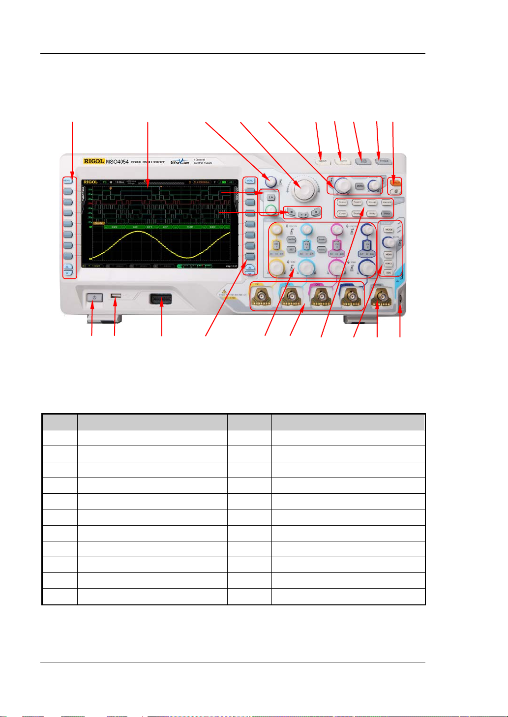
前面板总览
1 2
13 14 15 16 17 18 19 20 21 22
表 1 前面板说明
3 4 5
11
12
图 11 前面板总览
6 7 8 9 10
1
2 LCD 13
3
4
5
6
7
8
9
10
11
MSO4000/DS4000 快速指南
种参数测量菜单软键
多功能旋钮
导航旋钮
水平控制区
全部清除键
波形自动显示
运行控制键
单次触发控制键
默认配置/打印键
逻辑分析仪控制区
12
14
15
16
17
18
19
20
21
22
波形录制按键
电源键
USB HOST 接口
数字通道输入端
功能设置菜单软键
垂直控制区
模拟通道输入端
功能菜单键
触发控制区
外触发输入端
探头补偿器信号输出端/接地端
Page 19

后面板总览
1. 触发输出/自校正
该连接器可输出多种信号(按 Utility Aux 输出,选择所需的输出类型。):
1) 触发输出:选择该类型后,示波器产生一次触发时,输出一个可反映示波器
当前的捕获率的信号。
2) 快沿:选择该类型后,可输出一个快沿信号,该信号可用于示波器的自校正。
3) GND:选择该类型后,可输出一个接地电平。
4) 通过失败:选择该类型后,当示波器测试到失败的波形,将输出一个脉冲信
号,将该信号转接到其他控制系统中可方便查看测试结果。
2. 参考时钟
使用参考时钟可以为示波器提供更准确的采样时钟信号,还可同步两台或多台示
波器的时钟。
3. 视频输出
通过该接口将示波器与外部显示器相连,可以观察到更清晰的波形显示。注意此
时示波器的显示屏仍然有效。
4. LAN
通过该接口将示波器连接到局域网中,对其进行远程控制。本示波器符合 LXI-C
类仪器标准,可快速搭建测试系统,并通过网页访问。
5. USB DEVICE
通过该接口可连接打印机以打印数据波形,或者连接 PC,通过上位机软件对示波
1 2 3 4 5 6 7 8
图 12 后面板总览
RIGOL
MSO4000/DS4000 快速指南 9
Page 20
RIGOL
10
器进行控制。
6. USB HOST
通过该接口可连接打印机以打印波形数据,或插入 U盘以存储波形文件。可以使
用 RIGOL 提供的 USB-GPIB 转接模块(选配)实现 GPIB 接口通信。注意示波器
前面板也提供了该接口。
7. 锁孔
可以使用安全锁(用户自行购买)通过该锁孔将示波器锁定在固定位置。
8. AC 电源插孔/开关
AC 电源输入端。本示波器的供电要求为 100-127 V,45-440 Hz 和 100-240 V,
45-65 Hz,CAT II。请使用附件提供的电源线将示波器连接到 AC 电源中。之后,
打开 AC 电源开关,示波器已上电。按下前面板电源键即可开机。
前面板功能概述
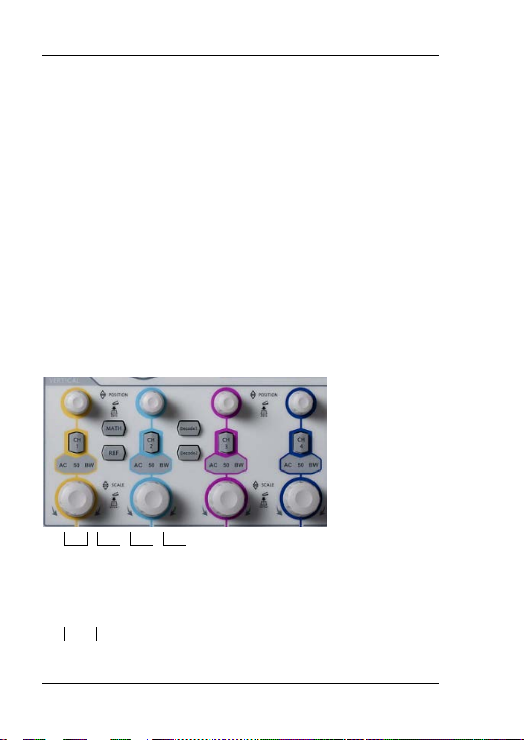
垂直控制
MSO4000/DS4000为四个模拟输入通道提供单独的垂直控制系统。
CH1、CH2、CH3、CH4:模拟输入通道。4 个通道标签用不同颜色标识,并且
屏幕中的波形和通道输入连接器的颜色也与之对应。按下任一按键打开相应通道
菜单,再次按下关闭通道。
AC:通道耦合方式为 AC 时变亮。
50:通道输入阻抗为 50 Ω 时变亮。
BW:带宽限制打开时变亮。
MATH:按下该键打开数学运算功能菜单。可进行加、减、乘、除、FFT、逻辑
和高级运算。
MSO4000/DS4000 快速指南
Page 21

RIGOL
REF:按下该键打开参考波形功能。可将实测波形和参考波形比较。
垂直 POSITION:垂直位移旋钮。修改位移时,屏幕左下角的位移标识实时变
化。顺时针转动增大位移;逆时针转动减小位移;按下旋钮可快速将垂直偏移归
零。
垂直 SCALE:垂直档位旋钮。修改档位时,屏幕下方的档位实时变化。顺时针
转动减小档位,步进为 5-2-1;逆时针转动增大档位,步进为 1-2-5;按下旋钮切
换刻度调整方式为“粗调/微调”。
Decode1、Decode2 :解码功能按键。按下相应的按键打开解码功能菜单。
MSO4000/DS4000支持并行解码和协议解码。
水平控制
MENU:按下该键打开水平控制菜单。可开关延迟扫描功能、切换不同的时基模
式,切换档位的微调和粗调,以及修改水平参考设置。
水平 SCALE:修改水平时基。顺时针转动减小时基,逆时针转动增大时基。修
改过程中,所有通道的波形被扩展或压缩显示,同时屏幕上方的时基信息(如
)实时变化。按下该旋钮可快速切换至延迟扫描状态。
水平 POSITION:修改触发位移。转动旋钮时触发点相对屏幕中心左右移动。
修改过程中,所有通道的波形左右移动,同时屏幕右上角的触发位移信息(如
)实时变化。按下该旋钮可快速复位触发位移(或延迟扫描位
移 )。
MSO4000/DS4000 快速指南 11
Page 22

RIGOL
12
”状态,
整垂直档位、水平时基以及触发方式,使波形显示达到最佳状态,
触发
触发控制
MODE:按下 该键切换触发方式为 Auto、 Normal 或
Single,当前触发方式对应的状态背灯会变亮。
针转动减小电平。修改过程中,触发电平线上下移动,同时
屏幕左下角的触发电平消息框(如 )中的值实时变
化。按下该旋钮可快速将触发电平恢复至零点。
MENU:按下该键打开触发操作菜单。本示波器提供丰富的
触发类型。
FORCE:在 Normal 和 Single 触发方式下,按下该键将强
制产生一个触发信号。
50%:按下该键将触发电平设置为触发信号幅值的垂直中
点。
LEVEL:修改触发电平。顺时针转动增大电平,逆时
全部清除
按下该键清除屏幕上所有的波形。如果示波器处于“RUN
则继续显示波形。
波形自动显示
按下该键启用波形自动设置功能。示波器将根据输入信号自动调
注意,应用自动设置要求被测信号的频率不小于 50 Hz,占空比大于 1%,幅度至少
为 20 mVpp,如果超出此参数范围,按下该键后会弹出“Auto 失败!”消息框而且菜
单可能不显示快速参数测量功能。
并提供快速参数测量功能。
MSO4000/DS4000 快速指南
Page 23

运行控制
按下该键将示波器的运行状态设置为“运行”或“停止”。“运行”
”。单次触发方式下,
单次触发
多功能旋钮
RIGOL
状态下,该键黄灯点亮。“停止”状态下,该键红灯点亮。
按下该键将示波器的触发方式设置为“Single
示波器将在符合触发条件下进行一次触发,然后停止。
该旋钮可用于调节参数的大小、波形的亮度,还可用于选择菜单(操作时,背灯变亮)。
输入参数时,顺时针转动增大参数值;逆时针转动减小参数值。
非菜单操作时(菜单隐藏),转动该旋钮可调整波形显示的亮度。亮度可调节范
围为 0%至 100%。顺时针转动增大波形亮度,逆时针转动减小波形亮度。按下
旋钮将波形亮度恢复至 50%。进入 Display 波形亮度 菜单,同样可通过该
旋钮调节波形亮度。
菜单操作时,按下某个菜单软键后,转动该旋钮还可用于选择该菜单下的子菜单,
然后按下旋钮可选中当前选择的子菜单。还可以用于修改参数、文件名输入等。
MSO4000/DS4000 快速指南 13
Page 24

RIGOL
14
状态,按下该键执行打印功能;
”
放的波形帧(“当前帧”菜单)。类似的菜单还有:触
导航旋钮
对于某些可设置范围较大的数值参数,该旋钮提供了
快速调节/定位的功能。顺时针(逆时针)旋转增大
(减小)数值;内层旋钮可微调,外层旋钮可粗调,
外层旋钮旋转的幅度越大,数值变化的速度越快。例
如,在回放波形时,使用该旋钮可以快速定位需要回
默认配置
打印键
发释抑、脉宽设置、斜率时间等。
按下该键,示波器将恢复为默认配置。
按下该键执行打印功能或将屏幕保存到U盘中。当前已连接
打印机,并且打印机处于空闲
当前未连接打印机,但连接 U盘,按下该键将屏幕以“.bmp
格式图片保存到 U 盘中(若当前存储类型为图像存储时,会
以指定的图片格式保存到 U 盘中)。同时连接打印机和 U 盘
时,打印机优先级较高。
MSO4000/DS4000 快速指南
Page 25

RIGOL
录制
回放/暂停
停止
停止 回放/暂停 录制
功能按键
Measure:按下该键进入测量设置菜单。可设置与测量相关的参数。
Acquire:按下该键进入采样设置菜单。可设置示波器的获取方式、存储深度和
抗混叠功能。
Storage:按下该键进入文件存储和调用界面。可存储的文件类型包括:轨迹存
储、波形存储、设置存储、图像存储和 CSV 存储。支持内、外部存储和磁盘管理。
Cursor:按下该键进入光标测量菜单。示波器提供手动测量、追踪测量和自动测
量三种光标模式。
Display:按下该键进入显示设置菜单。设置波形显示类型、余辉时间、波形亮
度、屏幕网格、网格亮度和菜单保持时间。
Utility:按下该键进入系统功能设置菜单。设置系统相关功能或参数,例如接口、
扬声器、语言等。此外,还支持一些高级功能,例如通过/失败测试和打印设置等。
Record:按下该键系统进入波形录制菜单。示波器提供波形录制功能并支持录
制常开模式,回放和分析已录制波形。
Help:按下该键打开帮助界面。详情请参考“使用内置帮助系统”中的介绍。
波形录制
MSO4000/DS4000 快速指南 15
:按下该键开始波形录制,按键背灯为红色。此外,打开录制常开模式时,
该按键背灯点亮。
放,按键背灯为黄色。
:按下该键停止正在录制或回放的波形,按键背灯为橙色。
:在停止或暂停的状态下,按下该键回放波形,再次按下该键暂停回
Page 26

RIGOL
16
LA
逻辑分析仪
LA_ :使用该旋钮可以重新排列数字通道。连续按下该旋
注意:该功能仅适用于 MSO4000 系列数字示波器。
:按下该键打开逻辑分析仪设置界面。您可以打开或关
闭通道组或任意通道、更改数字通道的显示大小、更改数字
通道的逻辑阈值、对 16 个数字通道进行分组并将其显示为
总线,您还可以为每一个数字通道设置标签。
钮可以按照数字通道编号(从小至大)依次切换当前打开的
数字通道,选中的通道突出显示为红色,旋转该旋钮将其移
至所需位置,再次按下旋钮固定该通道的位置同时选中下一
通道。
MSO4000/DS4000 快速指南
Page 27

RIGOL
用户界面
MSO4000/DS4000示波器提供 9英寸 WVGA(800*480)160,000色 TFT LCD。值得
一提的是,14 格超宽的屏幕可让您观察到更“长”时间的波形。
1 2 3 4 5 6 7 8 9 10 11 12
13 14 15 16 17 18 19 20
图 13 用户界面
1. 自动测量选项
提供 12 种水平(HORIZONTAL)和 12 种垂直(VERTICAL)测量参数。按下屏
幕左侧的软键即可打开相应的测量项。
2. 模拟通道标记/波形
不同通道用不同的颜色表示,通道标记和波形的颜色一致。
3. 数字通道标记/波形
数字波形的逻辑高电平显示为蓝色,逻辑低电平显示为绿色与通道标记颜色一
致,边沿呈白色。当前选中的数字通道标记和波形均显示为红色。
MSO4000/DS4000 快速指南 17
Page 28

RIGOL
18
注意:该功能仅适用于 MSO4000 系列数字示波器。
4. 运行状态
可能的状态包括:RUN(运行)、STOP(停止)、T’D(已触发)、WAIT(等待)
和 AUTO(自动)。
5. 水平时基
表示屏幕水平轴上每格所代表的时间长度。
使用水平 SCALE 可以修改该参数,可设置范围为 1.000 ns 至 1000 s。
6. 采样率/存储深度
显示当前示波器使用的采样率以及存储深度。
使用水平 SCALE 可以修改该参数。
7. 波形存储器
提供当前屏幕中的波形在存储器中的位置示意图。
屏幕中的波形
8. 触发位置
显示波形存储器和屏幕中波形的触发位置。
9. 水平位移
使用水平 POSITION 可以调节该参数。按下旋钮时参数自动被设为 0。
10. 触发类型
显示当前选择的触发类型及触发条件设置。选择不同触发类型时显示不同的标
识。
例如,
表示在“边沿触发”的上升沿处触发。
11. 触发源
显示当前选择的触发源(CH1-CH4、EXT、EXT/5、市电或 D0-D15)。选择不同
触发源时,显示不同的标识,并改变触发参数区的颜色。
例如,
表示选择 CH1 作为触发源。
12. 触发电平/阈值
当触发信源选择 CH1 至 CH4 时,屏幕右侧将出现触发电平标记 ,右上角
为触发电平值。注意:欠幅脉冲触发和斜率触发时,有两个触发电平标记(
和 )。
使用触发 LEVEL 修改触发电平时,触发电平值会随 的上下移动而改变。
当选择触发信源选择 D0 至 D15 时,右上角的数值变为触发阈值,此时无触
发电平标记(仅适用于 MSO4000 系列)。
13. CH1 垂直档位
显示屏幕垂直方向 CH1 每格波形所代表的电压大小。
使用垂直 SCALE 可以修改该参数。
MSO4000/DS4000 快速指南
Page 29

此外还会根据当前的通道设置给出如下标记:“通道耦合”(如交流耦合时显
示“
入阻抗为 50Ω 时显示“
”)、“ 带宽限制”(如带宽限制打开时显示“ ”)、“ 输入阻抗”( 如 输
”)。
14. CH2 垂直档位
显示屏幕垂直方向 CH2 每格波形所代表的电压大小。
使用垂直 SCALE 可以修改该参数。
此外还会根据当前的通道设置给出如下标记:“通道耦合”( 如交流耦合时显
示“
入阻抗为 50Ω 时显示“
”)、“ 带宽限制”( 如带宽限制打开时显示“ ”)、“ 输入阻抗”( 如输
”)。
15. CH3 垂直档位
显示屏幕垂直方向 CH3 每格波形所代表的电压大小。
使用垂直 SCALE 可以修改该参数。
此外还会根据当前的通道设置给出如下标记:“通道耦合”( 如交流耦合时显
示“
入阻抗为 50Ω 时显示“
”)、“ 带宽限制”( 如带宽限制打开时显示“ ”)、“ 输入阻抗”( 如输
”)。
16. CH4 垂直档位
显示屏幕垂直方向 CH4 每格波形所代表的电压大小。
使用垂直 SCALE 可以修改该参数。
此外还会根据当前的通道设置给出如下标记:“通道耦合”( 如交流耦合时显
示“
”)、“ 带宽限制”( 如带宽限制打开时显示“ ”)、“ 输入阻抗”( 如输入
阻抗为 50Ω 时显示“
”)。
17. 消息框
显示提示消息。
18. 数字通道状态区
显示 16 个数字通道当前的状态。从右至左依次为 D0 至 D15,当前打开的数字通
道显示为绿色,当前选中的数字通道突出显示为红色。在数字通道活动区中任何
已关闭的数字通道均显示为灰色。
注意:该功能仅适用于 MSO4000 系列数字示波器。
19. 通知区域
显示系统时间、声音图标和 U 盘图标。
系统时间:以“hh:mm(时:分)”的格式显示。在打印或存储波形时,输出
文件将包含该时间信息。按 Utility 系统 系统时间,通过下面格式设
置:
yyyy-mm-dd hh-mm-ss (年-月-日 时-分-秒)
RIGOL
声音图标:声音打开时,该区域显示 。按 Utility 声音 可以打开或关
闭声音。
MSO4000/DS4000 快速指南 19
Page 30

RIGOL
20
U 盘图标:当示波器检测到 U盘时,该区域显示 。
20. 操作菜单
按下任一软键可激活相应的菜单。下面的符号可能显示在菜单中:
表示可以用前面板上的多功能旋钮
选择参数项。 的背灯在参数
选择有效时变亮。
表示可以用 修改参数值。 的背灯在参数输入有效时变亮。
表示可以用导航旋钮快速调节/定位参数。
表示使用 选择参数,然后按下
选中参数。
表示当前菜单有若干选项。
表示当前菜单有下一层菜单。
按下该键可以返回上一级菜单。
注意,操作菜单左下角的网格中也可能出现下面的方向键:
表示可以打开下一页菜单。
表示可以返回上一页菜单。
使用安全锁
如有必要,您可以使用安全锁(请自行购买)将示波器锁在固定位置。方法如下,沿
与后面板垂直的方向对准锁孔将锁头插入,顺时针旋转钥匙锁定示波器,然后拔出钥
匙。
安全锁孔
图 14 使用安全锁
注意:请勿将其它物品插入安全锁孔以免损坏仪器。
MSO4000/DS4000 快速指南
Page 31

RIGOL
使用内置帮助系统
本示波器的帮助系统提供了前面板各功能键(包括菜单键)的说明。按 Help 键打开
帮助界面,再次按下则关闭。帮助界面主要分两部分,左边为“帮助选项”,可使用
“Button”或“Index”方式选择,右边为“帮助显示区”。
帮助选项 帮助显示区
图 15 帮助信息
Button
默认方式。该方式下,您可以直接按面板上的按键(电源键
单翻页键
:
、多功能旋钮 和菜
/ 除外)或旋转导航旋钮即可在“帮助显示区”中获得相应按键的帮助
信息。
使用
选择“To Index”后按下旋钮可切换到 Index 方式。
Index
该方式下,使用
:
选择需要获得帮助的选项(例如“带宽”),当前选中的选项显示
棕黄色底纹,按下旋钮,即可在“帮助显示区”中获得相应的帮助信息。
使用
选择“To Button”后按下旋钮可切换到 Button 方式。
MSO4000/DS4000 快速指南 21
Page 32

RIGOL
22
故障处理
下面列举了示波器在使用过程中可能出现的故障及排查方法。当您遇到这些故障时,
请按照相应的步骤进行处理,如不能处理,请与 RIGOL 公司联系,同时请提供您机
器的设备信息(获取方法:Utility 系统 系统信息)。
1. 如果按下电源键示波器仍然黑屏,没有任何显示:
(1) 检查电源接头是否接好。
(2) 检查电源开关是否打开。
(3) 做完上述检查后,重新启动仪器。
(4) 如果仍然无法正常使用本产品,请与 RIGOL 联系。
2. 采集信号后,画面中并未出现信号的波形:
(1) 检查探头是否正常接在信号连接线上。
(2) 检查信号连接线是否正常接在 BNC(即通道连接器)上。
(3) 检查探头是否与待测物正常连接。
(4) 检查待测物是否有信号产生(可将探头补偿输出信号连接到有问题的通道确
定是通道还是待测物的问题)。
(5) 再重新采集信号一次。
3. 测量的电压幅度值比实际值大或者小(注意,此处一般在使用探头时才会出现):
检查通道衰减系数是否与实际使用的探头衰减比例相符。
4. 有波形显示,但不能稳定下来:
(1) 检查触发信源:检查触发面板的 信源选择 是否与实际使用的信号通道相
符。
(2) 检查触发类型:一般的信号应使用“边沿触发”方式,视频信号应使用“视
频触发”方式。只有应用适合的触发方式,波形才能稳定显示。
(3) 尝试改变 耦合 为“高频抑制”或“低频抑制”显示,以滤除干扰触发的高
频或低频噪声。
(4) 改变触发释抑设置。
5. 按下 RUN/STOP 键无任何显示:
检查触发面板(TRIGGER)的 触发方式 是否为“普通”或“单次”档,且触发
电平是否超出波形范围。如果是,将触发电平居中或者设置 触发方式 为“自动”
档。
MSO4000/DS4000 快速指南
Page 33

注意:使用自动设置 AUTO 按钮可自动完成以上设置。
6. 波形显示呈阶梯状:
(1) 水平时基档位可能过低,增大水平时基以提高水平分辨率,可以改善显示。
(2) 若 显示类型 为“矢量”,采样点间的连线,可能造成波形阶梯状显示。将 显
示类型 设置为“点”显示方式,即可解决。
7. 通过 USB 连接 PC 或打印机失败:
检查 Utility 的 接口设置 菜单中,USB 设备 中的设置是否与当前连接的设备
匹配。必要时重启示波器。
8. U 盘不能被识别:
(1) 检查 U 盘是否可以正常工作。
(2) 确认使用的为 Flash 型 U 盘,本仪器不支持硬盘型 U 盘。
(3) 确认使用的 U 盘容量是否过大,本示波器推荐使用不超过 8 GBytes 的 U 盘。
(4) 重新启动仪器后,再插入 U 盘进行检查。
(5) 如果仍然无法正常使用 U 盘,请与 RIGOL 联系。
RIGOL
MSO4000/DS4000 快速指南 23
Page 34

Page 35

RIGOL
I
Guaranty and Declaration
Copyright
© 2013 RIGOL Technologies, Inc. All Rights Reserved.
Trademark Informat ion
RIGOL is a registered trademark of RIGOL Technologies, Inc.
Publicatio n Number
QGA15103-1110
Notices
RIGOL products are pr o t ec t ed by patent law in and outside of P.R.C.
RIGOL reserves the right to modify or change parts of or all the specifications and pricing
policies at company’s sole decision.
Information in this publication replaces all previously corresponding materials.
RIGOL shall not be liable for losses caused by either incidental or consequential in
connection with the furnishing , use or performa nce of this manual as well as any inf ormation
contained.
Any part of this document is forbidden to be copied or photocopied or rearranged without
prior written approval of RIGOL.
Product Certification
RIGOL guarantees this product conforms to the national and industrial standards in China as well
as the ISO9001:2008 standard and the ISO14001:2004 standard. Other international standard
conformance certification is in progress.
Contact Us
If you have any pro blem o r requ irement when usin g our produc ts or this manual , ple ase c ont act
RIGOL.
E-mail: service@rigol.com
Website: www.rigol.com
MSO4000/DS4000 Quick Guide
Page 36

RIGOL
II
Safety Requirement
General Safety Summary
Please review the following safety precautions carefully before putting the instrument into
operation so as to avoid any personal injuries o r damages to the instrum ent and any product
connected to it. To prevent po tential hazards, please use t he instrument only specifi ed by this
manual.
Use Proper Power Cord.
Only the power cord designed for the instrument and authorized by local country could be used.
Ground The Instrument.
The instrument is grounded through the Protective Earth lead of the power cord. To avoid electric
shock, it is essential to connect the earth terminal of power cord to the Protective Earth terminal
before any inputs or outputs.
Connect the Probe Correctly.
Do not connect the ground lead to high voltage since it has the isobaric electric potential as ground.
Observe All Terminal Ratings.
To avoid f ire o r sh ock ha zard, obser ve al l ratings and m arkers on t he in strum ent and check your
manual for more information about r a t i ngs be fore connecting.
Use Proper Overvoltage Protection.
Make sure that no overvoltage (such as that caused by a thunderstorm) can reach the product, or
else the operator might expose to danger of electrical shock.
Do Not Operate Without Covers.
Do not operate the instrument with cover s or panels removed.
Avoid Circuit or Wire Exposure.
Do not touch exposed junctions and components when the unit is powered.
Do Not Operate With Suspected Failures.
If you suspect damage occurs to the instrument, have it inspected by qualified service personnel
before further operations. Any maintenance, adjustment or replacement especially to circuits or
accessories must be performed by RIGOL authorized personnel.
Keep Well Ventilation.
Inadequate ventilation may cause increasing of temperature or damages to the device. So please
keep well ventilated and inspect the intake and fan regularly .
Do Not Operate in Wet Conditions.
In order to avoid sho rt circuiting to the in terior of the device o r electric shock, please do not
MSO4000/DS4000 Quick Guide
Page 37

RIGOL
III
operate in a humid environment.
Do Not Operate in an Explosive Atmosphere.
In order to avoid damages to the device or personal injuries, it is important to operate the device
away from an explosive atmosphere.
Keep Product Surfaces Clean and Dry.
To avoid the influence of dust and/or moisture in air, please keep the surface of device clean a nd
dry.
Electrostatic Prevention.
Operate in an electrostatic dischar ge protective ar ea environm ent to avoid d amages indu ced by
static discharges. Always ground both the internal and external conductors of the cable to release
static before connecting.
Handling Safety.
Please handle w ith care during transpo rtation to avoid damages t o buttons, knob inter faces and
other parts on the panels.
Safety Terms and Symbols
Terms in this Manual. The following terms may appear in this manual:
WARNING
Warning statements indicate the conditions or practices that could result in injuries or
loss of life.
CAUTION
Caution statements indicate the conditions or practices that could result in damage to
this product or loss of data.
Terms on the Product. The following terms may appear on the product:
DANGER indicates an injury or hazard may immediately happen.
WARNING indicates an injury or hazard may be accessible potentially.
CAUTION indicates a potential damage to the instrument or other property might occur.
MSO4000/DS4000 Quick Guide
Page 38

RIGOL
IV
Symbols on the Product. The following symbols may appear on the product:
Hazardous
Voltage
Safety Warning
Protective
Earth
Terminal
Chassis
Ground
Test
Ground
Measurement Category
Measurement Category
MSO4000/DS4000 series digital oscilloscopes can make measurements in Measurement Category I.
WARNING
This oscilloscope can only be used for measurements within its specified measurement
categories.
Measurement Category Definitions
Measurement category I is for measurements performed on circuits not directly connected to
MAINS. Examples are measurements on circuits not derived from MAINS, and specially protected
(internal) MAINS derived circuits. In the latter case, transient stresses are variable; for that reason,
the transient withstand capability of the equipment is made known to the user.
Measurement category II is for measurements performed on circuits directly connected to the low
voltage installation. Examples are measurements on household appliances, portable tools and
similar equipment.
Measurement category III is for measurements performed in the building installation. Examples are
measurements on distribution boards, circuit-breakers, wiring, including cables, bus-bars, junction
boxes, switches, socket-outlets in the fixed installation, and equipment for industrial use and some
other equipment, for example. Stationary motors with permanent connection to the fixed
installation.
Measurement category IV is for measurements performed at the source of the low-voltage
installation. Examples are electricity meters and measurements on primary overcurrent protection
devices and ripple control units.
MSO4000/DS4000 Quick Guide
Page 39

RIGOL
V
Ventilation Requirement
This oscilloscope uses fan to force cooling. Please make sure that the air intake and exhaust areas
are free from obst ruct ions and hav e free air. When using the osc illosc ope in a bench-top setting,
provide at least 10 cm clearance beside, above and behind the instrument for adequate ventilation.
WARNING
Inadequate ventilation may cause temperature increase which would damage the
instrument. So please keep the instrument well ventilated during operation and inspect
the intake and fan regularly.
Working Environment
Temperature
Operating: 0℃ to +50℃
Non-operating: -40℃ to +70℃
Humidity
0℃ to +30℃:≤95% relative humidity
+30℃ to +40℃:≤75% relative humidity
+40℃ to +50℃:≤45% relative humility
WARNING
To avoid short circuit inside the instrument or electric shock, please do not operate in
humid environment.
Altitude
Operating: less than 3 km
Non-operating: less than 15 km
Installation (overvo lta ge) Cat ego ry
This product is powered by MAINS conforming to installation (overvoltage) category II.
MSO4000/DS4000 Quick Guide
Page 40

RIGOL
VI
WARNING
Make sure that no overvoltage (such as that caused by thunderbolt) can reach the
product, or else the operator might expose to danger of electric shock.
Installation (overvoltage) Category Definitions
Installation (overvoltage) category I refers to signal level which is applicable to equipment
measurement terminals connected to the source circuit. In these terminals, precautions are done
to limit the transient voltage to the corresponding low level.
Installation (overvoltage) category II refers to the local power distribution level which is applicable
to equipment connected to the AC line (AC power).
Pollution Degree
Degree 2
Pollution Degree Definitions
Pollution deg ree 1 : No pol l ut i on or only dry, non-conductive pollution occurs. The pollution has no
influence. For example: a clean room or air-conditioned office environment.
Pollution degree 2: Normally only dry, non-conductive pollution occurs. Occasionally a temporary
conductivity caused by condensation may occur. For example: general indoor environment.
Pollution degree 3: Conductive pollution occurs, or dry, non-conductive pollution occurs which
becomes conductive due to condensation which is expected. For example: Sheltered outdoor
environment.
Pollution degree 4: Pollution that generates persist e nt conductivi ty t hroug h cond ucti ve dust, rain,
or snow. For example: outdoor locations.
Safety Class
Class 1 – Grounded Product
General Care and Cleaning
General Care:
Do not store or leave the instrument in where the instrument will be exposed to direct sunlight for
long periods of time.
MSO4000/DS4000 Quick Guide
Page 41

RIGOL
VII
Cleaning:
Clean the instrument regularly according to its operating conditions. To clean the exterior surface,
perform the following steps:
1. Disconnect the instrument from all power sources.
2. Clean the loose dust o n the outside of the in strument with a lint- free cloth (with a mild
detergent or water). When cleaning the LCD, take care to avoid scarifying it.
CAUTION
To avoid damages to the instrument, do not expose them to liquids which have
causticity.
WARNING
T o a void injury res ulting from short circuit, make sure the instrument is completely dry
before reconnecting to a power source.
Environmental Consideratio ns
The following symbol indicates that this product complies with the requirements of European Union
according to Directives 2002/96/EC on waste electrical and electronic equipment (WEEE).
Product End-of-Life Handling
The equipment may contain substances that could be harmful to the environment or human health.
In order to avoid release of such substances into the environment and harm to human health, we
encourage you to recycle this product in an appropriate system that will ensure that most of the
materials are reused or recycled appropriately. Please contact your local authorities for disposal or
recycling information.
MSO4000/DS4000 Quick Guide
Page 42

RIGOL
VIII
Contents
Guaranty and Declaration ................................................................................................ I
Safety Requirement ....................................................................................................... II
General Safety Summary .............................................................................................. II
Safety Terms and Symbols ........................................................................................... III
Measurement Category ............................................................................................... IV
Ventilation Requirement ................................................................................................V
Working Environment ....................................................................................................V
General Care and Cleaning .......................................................................................... VI
Environmental Considerations ..................................................................................... VII
Quick Start ....................................................................................................................... 1
General Inspection........................................................................................................ 1
Appearance and Dimensions .......................................................................................... 2
To Prepare for Operation ............................................................................................... 3
To Remove the Cover ............................................................................................ 3
To Adjust the Supporting Legs................................................................................ 3
To Connect to AC Power Supply .............................................................................. 4
Power-on Inspection ............................................................................................. 4
To Connect the Probe ............................................................................................ 5
Function Inspection ............................................................................................... 5
Probe Compensation ............................................................................................. 7
To Connect the Logic Pr obe ................................................................................... 7
Front Panel Overview .................................................................................................... 8
Rear Panel Overview ..................................................................................................... 9
Front Panel Function Overview ..................................................................................... 11
VERTICAL........................................................................................................... 11
HORIZONTAL...................................................................................................... 12
TRIGGER............................................................................................................ 13
CLEAR ............................................................................................................... 13
AUTO ................................................................................................................. 14
RUN/STOP.......................................................................................................... 14
SINGLE .............................................................................................................. 14
Knob .................................................................................................................. 15
Navigation Knob ................................................................................................. 15
Default ............................................................................................................... 16
Print .................................................................................................................. 16
Function Keys ..................................................................................................... 16
Record ............................................................................................................... 17
LOGIC ANALYZER ................................................................................................ 18
User Interface ............................................................................................................ 19
To Use the Security Lock ............................................................................................. 23
To Use the Built-in Help System ................................................................................... 24
Troubleshooting ............................................................................................................ 25
MSO4000/DS4000 Quick Guide
Page 43

1
Quick Start
General Inspection
1. Inspect the shipping container for damage
Keep the damaged shipping container or cushioning material until the contents
of the shipment have been checked for completeness and the instrument has
passed both ele ctrical and mechanical tests.
The consigner or carrier shall be liable for the damage to instrument resulting
from shipment. RIGOL would not be responsible for free maintenance/rework
or replacement of the unit.
2. Inspect the instrument
In case of any damage, or defect, or failure, notify your RIGOL sales
representative.
3. Check the accessories
Please check the accessories according to the packing lists. If the accessories
are incomplete or damaged, pleas e contact your RIGOL sales representative.
RIGOL
MSO4000/DS4000 Quick Guide
Page 44

RIGOL
2
Appearance and Dimensions
Figure 1 Front View Unit: mm
Figure 2 Side View Unit: mm
MSO4000/DS4000 Quick Guide
Page 45

RIGOL
3
To Prepare for Operation
To Remove the Cover
Before using the oscilloscope, remove the front panel cover by grasping the
transverse grab on each side and pull them in the arrow directions as shown in the
figure below.
Figure 3 To Rem ove th e Cover
To Adjust the Supporting Legs
Adjust the suppo rting legs properly to us e them as stands to tilt the oscilloscope
upwards, thus to place the oscilloscope stably and to operate an d observe the display
better. You can u nf old or f old the supp orting le gs in the ar row dire ctions as sh own in
the fi g ure below.
Figure 4 To Adjust the Supporting Legs
MSO4000/DS4000 Quick Guide
Page 46

RIGOL
4
AC Power Input Terminal
To Connect to AC Power Supply
This oscilloscope accepts two kinds of AC power supplies: 100-127V, 45-440Hz and
100-240V, 45-65Hz. Please use the power cord supplied with the accessories to
connect the oscilloscope to the power source. Turn on the power switch under t he
power plug; at this point, the oscilloscope is energized and the power key
the lower-left corner of the front panel is in breath state.
at
Figure 5 To Connect to AC Power Suppl y
Power-on Inspection
When the oscilloscope is energized, press the power key
corner of the front panel to start the oscilloscope. During the start-up process, the
oscilloscope performs a series of self-tests and you can hear the sound of relay
switching. After the self-test is finishe d, the welcome screen is displayed and yo u can
view the Option Type, Option name, Option Edition and Left time of the option
currently installed in the “Installed Options” pop-up dialog box on the screen. When
the instrument is shipped, a t rial version of the optio n is provided and the left time i s
about 2000 minutes. Press Utility System SelfTestInfo to view the self-test
results.
at the low er -left
MSO4000/DS4000 Quick Guide
Page 47

RIGOL
5
To Connect the Probe
RIGOL provides passive and active probes for the MSO4000/DS4000 series
oscilloscopes. For detailed technical information of the probes, please refer to the
corresponding Probe User’s Guide. The following are the probes recommended for
this oscilloscope.
Model Description
RP3500A 500 MHz, passive probe, standard, auto detection
RP7150 1.5 GHz, active probe, optional, auto detection
Connect the Probe:
1. Connect the BNC terminal of the probe to a channel BNC connector of the
oscilloscope at the front panel.
2. Connect the probe tip to the circuit point under test and connect the ground
alligator clip of the probe to the circuit ground terminal.
Figure 6 To Connect the Probe
Function Inspection
1. Press Default to restore the oscilloscope to its default configuration.
2. Connect the ground alligator clip of the pr obe to the “Ground Terminal” under the
“Compensation Signal Output Terminal”.
3. Connect the input terminal of CH1 of the oscilloscope with the “Compensation
Signal Output Terminal” of the probe using the probe.
MSO4000/DS4000 Quick Guide
Page 48

RIGOL
6
o avoid electric shock during the use of probe, please make sure that
Tip
probe compensation adjustment and can not be used for calibration.
Compensation Signal Output T erminal
Ground Terminal
Figure 7 To Use the Compensation Signal
4. Press the AUTO key.
5. Observe the wavef orm o n the displa y. In normal condition, the dis play s hould be
a square waveform as shown in the figure below:
Figure 8 Square Waveform
6. Use the same method to test the other channels. If the square waveforms
actually shown do not match that in the f igure above, please perform “Probe
Compensation” in the next section.
WARNING
T
the insulated wire of the probe is in good condition and do not touch
the metallic part of the probe when the probe is connected to high
voltage source.
The signal output from the probe compensation connector can only be used for
MSO4000/DS4000 Quick Guide
Page 49

RIGOL
7
Over compensated Perfectly compensated Under c ompensated
Probe Compensation
When the probes are used for the first time, you should compensate the probes to
match the input channels of the oscilloscope. Non-compensated or poorl y
compensate d probes may cause mea s ure m ent i n accurac y and error. The probe
compensation procedure is as follows:
1. Perform s tep 1, 2, 3 and 4 of “Function Inspection” in the previous section.
2. Check the displayed waveforms and compare them with the following figures.
Figure 9 Probe Compensation
3. Use a nonmetallic driver to adjust the variable capacitor on the probe until the
displayed waveform is as the “Perfectly compensated” in the figure above.
To Connect the Logic Probe
RIGOL provides logic probe for the MSO4000 series digital oscilloscope. For detailed
technical information of the logic probe, please refer to the corresponding Probe
User’s Guide.
Connect the logic probe single head to the digital channel input terminal [LOGIC
D0-D15] at the front panel of the MSO4000 series digital oscilloscope. Note:
connect the logic probe adaptor supplies with the accessories to the corresponding
branch header (called channel g roup) before connecting the logic probe to the devi ce
under test.
Figure 10 To Connect the Logic Probe
MSO4000/DS4000 Quick Guide
Page 50

RIGOL
8
Front Panel Overview
1 2
13 14 15 16 17 18 19 20 21 22
Figure 11 Front Panel Overview
Table 1 Front Panel Description
3 4 5
12
11
6 7 8 9 10
No. Description No. Description
1 Menu 12 Record
2 LCD 13 Power Key
3 Knob 14 USB HOST
4 Navigation Knob 15 Digital Channel Input Terminal
5 HORIZONTAL 16 Function Setting Menu Softkeys
6 CLEAR 17 VERTICAL
7 AUTO 18 Analog Channel Input Terminals
8 RUN/STOP 19 Function Menu Keys
9 SINGLE 20 TRIGGER
10 Default&Print 21 EXT TRIG Input Terminal
11 LOGIC ANALYZER 22 Probe Compensation Signal Output
Terminal/Ground Terminal
MSO4000/DS4000 Quick Guide
Page 51

9
Rear Panel Overview
1. Trig Out/Calibratio n
Various kinds of signals can be output from this connector (press Utility
AuxOutput to select the desired outpu t type).
1) TrigOut: the oscilloscope outputs a signal which can reflect the current
capture rate of the oscilloscope each time a trigger is generated.
2) Fast: the oscilloscope outputs a fast edge signal which can be used in the
self-calibration of the oscilloscope .
3) GND: the oscilloscope outputs a ground level.
4) PassFail: the oscilloscope outputs a pulse when failed waveform is
detected and the pulse can be transmitted to o ther control system for easy
view of the test result.
2. Reference Clock
Provide more precise sample clock signal for the oscilloscope and it can also
synchronize two or more oscilloscope clocks.
3. Video Output
Through this interface, the oscilloscope can be conne cted to external m onitors to
get clearer w aveform dis play. Note that the display of the oscilloscope is still
valid.
1 2 3 4 5 6 7 8
Figure 12 Rear Panel Overview
RIGOL
MSO4000/DS4000 Quick Guide
Page 52

RIGOL
10
4. LAN
Through this interface, the oscilloscope can be connected to the network for
remote cont rol. As t he osci lloscope conforms to the LXI-C instrument standard, a
test system can be built quickly an d accessed t hrough we b page.
5. USB DEVICE
Through this interface, the oscill osc ope can be c onnected to the printer or PC to
print data waveform or control the oscilloscope through PC software.
6. USB HOST
Through this interface, the oscilloscope can be connec ted to the printer to print
wavef orm data or be connected to a USB storage device to store waveform files.
GPIB interface communication can be realized by using the USB-GPIB interface
converter provided by RIGOL.
Note that there is also a USB HOST interface at the front panel.
7. Lock Hole
Use th e security lock (please buy it yourself) to lock the oscilloscope to a fixed
location.
8. AC Input/Switch
AC power input terminal. The power supply require ments of this oscilloscope are
100-127 V, 45-440 Hz and 100-240 V, 45-65 Hz; CAT II. Please connect the
oscilloscope to AC power using the power cord prov i de d with the accessories.
Then, turn on the AC power switch to energize the oscillosc ope. Press the power
key at the front panel to start the oscilloscope.
MSO4000/DS4000 Quick Guide
Page 53

RIGOL
11
Front Panel Function Overview
VERTICAL
MSO4000/DS4000 provi des independent vertical control systems for the four analog
input channels.
CH1, CH2, CH3, CH4: analog input channels. The four channels are marked
by different colors which are also used to mark both the corresponding
waveforms on the screen and the channel input connectors. Press any key to
open the corresponding channel menu and press again to turn off the channel.
AC: illuminated when AC channel coupling mode is enabled.
50: illuminated when the channel input impedance is 50 Ω.
BW: illuminated when bandwidth limit is enabled.
MATH: press this key to open the math operation menu under which add,
subtract, multiply, divide operations, FFT operation, logic operation and
advanced operation are p r o vided .
REF: press this key to enable t h e re fer e n c e wav efo r m fu nction t o c o mp ar e t h e
waveform actually tested with the reference waveform.
VERTICAL POSITION: vertical position knobs. During the modification,
the position label at the lower left corner of the sc reen would change a ccordingly.
Turn clockwise to increase the position and counterclockwise to decrease. Press
down the knob to quickly reset the vertical position to zero.
VERTICAL SCALE: vertical scale knobs. During the modification, the scale
label at the bottom of the screen would change accordingly. Turn clockwise to
decrease the scale with a step of 5-2-1 and turn counterclockwise to increase
MSO4000/DS4000 Quick Guide
Page 54

RIGOL
12
with a step of 1-2-5. Press down the knob to switch the vertical scale adjustment
mode between “Coarse” and “Fine”.
Decode1 and Decode2: decoding function keys. Press the corresponding key
to open the decoding function menu. MSO4000/DS4000 supports parallel
decoding and p rotocol decoding.
HORIZONTAL
MENU: press this key to open the horizont al control menu with which users can
turn on or off the delayed sweep function, switch between different time base
modes, switch between “Coarse” and “Fine” adjustments of scale as well as
modify the horizontal reference setting.
HORIZONTAL SCALE: modify the horizontal time base. Turn clockwise to
reduce the time base and turn counterclockwise to increase the time base.
During the modification, waveforms of all the channels will be displayed in
expanded or compressed mode and the time base message (e.g.
at the upper side of the screen would change accordingly. Press down the knob
to quickly switch to delayed sweep state.
HORIZONTAL
would move left or right relative to the center of the screen when you turn the
knob. During the modification, waveforms of all the channels would move left or
right and the trigger position message (e.g.
upper-right corne r of the screen w ould change accor dingly . P ress down the knob
to quickly reset the trigger position (or the delayed sweep position)
POSITION: modify the trigger position. The trigger point
) at the
)
MSO4000/DS4000 Quick Guide
Page 55

13
TRIGGER
MODE: press this key to switch the trigger mode to Auto,
RIGOL
Normal or Single and the state backlight of the current
trigger mode would be illuminated.
TRIGGER LEVEL: modify the trigger level. Turn clockwise
to increase the level and turn counterclockwise to reduce the
level. During the modification, the trigger level line moves up
and down and the value in the trigger level message box (e.g.
) at the lower-left corner of the screen would
MENU: press this key to turn on t he trig ger oper atio n menu. This oscillos cope
provides various trigger types.
FORCE: in Normal and Single trigger modes, press this key to generate a
trigger signal forcefully.
50%: press this key to set the trigger level to the vertical midpoint of the
trigger signal amplitude.
change accordingly. Press down the knob to quickly reset the
trigger level to zero point.
CLEAR
Press this key to clear all the waveforms on the screen. If the
oscilloscope is in “Run” state, waveforms will still be displayed.
MSO4000/DS4000 Quick Guide
Page 56

RIGOL
14
ote that auto set ting requires t hat the f requency of the signal unde r test shou ld be
AUTO
Press this key to enable the waveform auto setting function. The
oscilloscope will automatically adjust the vertical scale, horizontal
time base and trigger mode according to the input signal to realize
optimum waveform dis play . Besides, quick parameter measurement
function is also provided.
N
no lower than 50 Hz, the duty cycle be greater than 1% and the amplitude be at
least 20 mVpp. If the parameters exceed theses limits, “Auto failed” would be
displayed after pressing this key and the quick parameter measurement menu
might not be displayed.
RUN/STOP
Press this key to set the state of the oscilloscope to “Run” or “Stop”.
In “Run” state, the key is illuminated in yellow and red in “Stop”
state.
SINGLE
Press this key to set the trigger mode to “Single”. In single trigger
mode, the oscilloscope triggers when the trigger condition is met
and then stops.
MSO4000/DS4000 Quick Guide
Page 57

RIGOL
15
be used to quickly l ocate t he w a vef orm fr a me (“C urr ent
Knob
This knob can be used to adjust the value of the parameters, adjust the waveform
brightness and select the desired menu (the backlight turns on during the operation).
During parameter input, turn the knob clockwise to increase the parameter and
count erclockwise to decrease.
When the menu blanks off, rotate the knob to adjust the waveform brightness.
The adjustable range is from 0% to 100%. Turn the knob clockwise to increase
the waveform brightness and counterclockwise to decrease. Press down the
knob to reset the waveform brightness to 50%. Users can also press Display
WaveIntensity and then rotate the knob to adjust the waveform brightness.
During menu operation, after pressing a menu softkey, rotate the knob to switch
to t he desired su b-menu under that menu and then press down the knob to
select this sub-menu. You can also use it to modify parameter and input
filename.
Navigation K n ob
This knob provides quick Adjust/Locate fun ction for
numerical parameters with relatively larger settable
ranges. Turn t h e knob clockwise (counter-clockwise) to
increase (reduce) the value. Note that the inner knob is
used for fine adjustment and the outer knob for coarse
MSO4000/DS4000 Quick Guide
adjustment. The more the outer knob is rotated, the
faster the value will cha nge. F or example, this knob can
Frame” men u) to be playe d back in wa vefor m play back.
Similar menus include trigger holdoff, pulse width
setting, slope time etc.
Page 58

RIGOL
16
Press this key to restore the oscilloscope to its default
Default
configuration.
Press this key to execute print function or save the screen
in the USB storage device. If the oscilloscope is currently
connected to a printer and the printer is in i dle state, press
this key to execute print function. If no printer but a USB
storage device is currently connected, press this key to
save the screen to the USB storage device in “.bmp” format
(if the current storage type is picture, the screen will be
stored in the USB storage device in picture format). When
printer and USB storage device are connected at the same
time, the printer enjoys higher priority.
Function Keys
Measure: press this key to enter the measurement setting menu to set the
measurement-related parameters.
Acquire: press this key to enter the sample setting menu to set t he acquisition
mode, the memory depth and the antialiasing function of the oscilloscope.
Storage: press this key to enter the file store and recall interface. The storable
file types include traces, waveforms, setups, picture and CSV. This instrument
supports internal and external storage as well as disk management.
Cursor: press this key to enter the cursor measurement menu. The oscilloscope
MSO4000/DS4000 Quick Guide
Page 59

RIGOL
17
Stop Play/Pause Record
provides thre e cursor modes: manual, track and auto.
Display: press this key to enter the display setting menu to set the dis play type,
persistence time, wave intensity, grid type, grid brightness and menu display
time o f t he waveform.
Utility: press this key to enter the system function setting menu to set the
system-related functions or parameters, such as I/O setting, sound and
language. The oscilloscope also supports some advanced functions such as
pass/fail test and print setting.
Record: press this key to enter the waveform record menu. The oscilloscope
provides wavef orm record function and supports rec ord constant ope n mode as
well as playback and analysis of recorded waveform.
Help: press this key to open the help interface. For detailed information, pleas e
refer to the introduction in “To Use the Built-in Help Syste m ”.
Record
Record: press this key to start recording the waveform. The backlight is
illuminated in red. Besides, the backlight will also be illuminated when record
constant on (open) mode is enabled.
Play/Pause: in stop or pause state, press this key to play back the wavefo rm
and press again to pause the play. The backlight is illuminated in yellow.
Stop: press this key to stop the waveform in record or p layback mode. The
backlight is illuminated in orange.
MSO4000/DS4000 Quick Guide
Page 60

RIGOL
18
LA
LOGIC ANALYZER
LA_ : this knob can be used to reposition the digital
Note: this function is only available for MSO4000 series digital oscilloscope.
: press this key to enter the logic analyzer setting
interface. You can enable or disable groups of channels or
a single channel, change the display size and the logic
threshold of the digital channels and group the 16 digital
channels and display them as a bus. You also can set a
label for each digital channel.
channels. Press this knob continu ously to swit ch the digital
channels currently enabled by the number of the digital
channel (from small to large) and the channel selected is
highlighted in red. Rotate the knob to move the digital
waveform to desired position, press this knob again to fix
this channel and select the next channel.
MSO4000/DS4000 Quick Guide
Page 61

RIGOL
19
13 14 15 16 17 18 19 20
User Interface
MSO4000/DS4000 oscilloscope pro vi des 9 inches, WVGA (800*480) 160,000 color
TFT LCD. What is worth mentioning is that the 14-grid ultra-wide screen makes you
view “longer” waveform.
1 2 3 4 5 6 7 8 9 10 11 12
Figure 13 User Interfa ce
1. Measurement Menu
Provide 12 horizontal (HORIZO NTAL) and 12 vertical (VERTICAL)
measurement parameters. Press the softkey at the left of the screen to
activate corresponding measurement item.
2. Analog Channel Label/Waveform
Different channels are marked by different colors and the color of the
waveform complies with the color of the channel.
3. Digital Channel Label/Waveform
MSO4000/DS4000 Quick Guide
Page 62

RIGOL
20
The logic high levels of the digital waveforms are displayed in blue, the logic
low levels are displayed in green which complies with the color of the digital
channel label and the edges are displayed in white. Both the label and the
waveform of the digital channel currently selected are displayed in red.
Note: this function is only available for MSO4000 series digital oscilloscope.
4. Status
Available states include RUN, STOP, T’D (triggered), WAIT and AUTO.
5. Horizontal Time Base
Represent t he time p er grid on the horizontal axis on the screen.
Use HORIZONTAL
SCALE
to modify this parameter. The range
available is from 1.000 ns to 1000 s.
6. Sample Rate/Memo ry Depth
Display the current sample rate and memory depth of the oscilloscope.
Use HORIZONTAL
SCALE to modify this parameter.
7. Waveform Memory
Provide the schematic diagram of the memory position of the waveform
currently on the screen.
waveform on the
screen
8. Trigger Position
Display the trigger position of the waveform in the waveform memo ry and
on the screen.
9. Horizontal Position
Use HORIZONTAL
POSITION to modify this parameter. Press down
the knob to automatically set the parameter to zero.
10. Trigger Type
Display the currently selected trigger type and trigger condition setting.
Different labels are displayed when different trigger types are selected.
For example:
represents triggering on the rising edge in “Edge” trigger.
11. Trigger Source
Display the trigger source (CH1-CH4, EXT, EXT/5, AC L ine or D 0-D15)
currently selected. Different labels are displayed when different trigger
sources are sel e cted an d t he colo r o f t he t ri gger pa r a met er a rea w ill cha n ge
accordingly.
For example:
MSO4000/DS4000 Quick Guide
denotes that CH1 is selecte d as the trigger so urce.
Page 63

21
12. Trigger Level/threshold
The trigger level label
will be displayed at the right of the screen
when the trigger source is selected CH1 to CH4 and the trigger level
value is displayed at the upper-right corner of the screen. Note: in runt
trigger and slope trigger, there are two trigger level labels (
).
When Using TRIGGER
trigger level value will change with the up and down of
There is no trigger level label
LEVEL to modify the trigger level, the
.
displayed when the trigger source is
selected D0 to D15 and the trigger threshold is displayed at the
upper-right corner of the screen (only available for MSO4000 series
digital oscilloscope.).
13. CH1 Vertical Scale
Display the voltage value per grid of CH1 wa veform vertically.
Use VIRTICAL
SCALE to modify this par ameter.
The following labels will be provided according to the current channel
setting: channel coupling (e.g.
in AC coupling), ban dwidth limit (e .g .
when bandwidth limit is enabled) and input impedance (e.g.
when the input impedance is 50Ω).
14. CH2 Vertical Scale
Display the voltage value per grid of CH2 waveform vertically.
Use VIRTICAL
SCALE to modify this par ameter.
The following labels will be provided according to the current channel
setting: channel coupling (e.g.
in AC coupling), ban dwidth limit (e .g .
when bandwidth limit is enabled) and input impedance (e.g.
when the input impedance is 50Ω).
15. CH3 Vertical Scale
Display the voltage value per grid of CH3 waveform vertically.
Use VIRTICAL
SCALE to modify this par ameter.
The following labels will be provided according to the current channel
setting: channel coupling (e.g.
in AC coupling), bandwidth limit (e.g.
when bandwidth limit is enabled) and input impedance (e.g.
when the input impedance is 50Ω).
16. CH4 Vertical Scale
Display the voltage value per grid of CH4 waveform vertically.
Use VIRTICAL
SCALE to modify this parameter.
The following labels will be provided according to the current channel
RIGOL
and
MSO4000/DS4000 Quick Guide
Page 64

RIGOL
22
setting: channel coupling (e.g. in AC coupling), bandwidth limit (e.g.
when bandwidth limit is enabled) and input impedance (e.g.
when the input impedance is 50Ω).
17. Message Box
Display prompt messages.
18. Digital Channel Status Area
Display the current state of the 16 digital channels. It is D0 to D15 from right
to left. The digital channels cur rently ena bled are displayed in green and the
digital channel currently selected is highlighted in red. Any digital channel
that is turned off will be grayed out in the Digital Channel Status Area.
Note: this function is only available for MSO4000 series digital oscilloscope.
19. Notification Area
Display system time, sound icon and USB storage device icon.
System Time: displayed in “hh:mm (hour:minute)” format. When
printing or storing the waveform, the output file will contain this time
message. Press Utility System Syste m Time to set the time in
the following format:
yyyy-mm-dd hh-mm-ss (year-month-dat e hour-minute-second)
Sound Icon: when sound is enabled,
is displayed. Press Utility
Sound to turn the sound on or off.
USB Storage Device Icon: when the oscilloscope detects a USB storage
device,
is displayed.
20. Operation Menu
Press any softkey to activate the corresponding menu. The following
symbols might be displayed in the menu:
Denote that
items. The backlight of
at the front panel can be used to select parameter
turns on when parameter selection is
valid.
Denote that
backlight of
Denote that you can use the nevigation knob to quickly adjust/locate
can be used to mod ify paramete r value. The
turns on when parameter input is valid.
parameters.
Denote that users can rotate and then press down
to select the
desired paramet er.
Denote that the current menu has several options.
Denote that the current menu has a lower level menu.
MSO4000/DS4000 Quick Guide
Page 65

RIGOL
23
Press this key to return to the previous menu.
Note that the following direction keys might appear in the grid at the
lower-left corner of the menu bar:
Denote that you can open the next page menu.
Denote that you can open the previous page menu.
To Use the Security Lock
If needed, you can use the security lock (please buy it yourself) to lock the
oscilloscope to a fixed location. The method is as follows, align the lock wit h the lo ck
hole and plug it into the lock hole vertically, turn the key clockwise to lock the
oscilloscope and then pull the key out.
Security Lock Hole
Figure 14 To Use the Security Loc k
Note: do not insert other articles into the security lock hole to avoid damaging the
instrument.
MSO4000/DS4000 Quick Guide
Page 66

RIGOL
24
To Use the Built-in Help System
The help system of this oscilloscope provides instructions for all the function keys
(including menu keys) at t he front panel. Press Help to open the help interface and
press ag ain to clos e the inter face. The help interface mainly consists of two parts.
The left is “Help Options” and you can use “Button” or “Index” mode for selection.
The right is “Help Display Area”.
Help Options Help Display Area
Figure 15 Help Information
Button:
Default mode. In this mode, you can press the button (ex cep t th e pow er key
the knob
and menu page up/ down key / ) or rotate the knob at the front
panel directly to get the corresponding help information of that button in the “Help
Display Area”.
Use
to select “To I nd e x” and then press down the knob to switch to Index
mode.
Index:
In this mode, use
to select th e item that needs to get help (for example: “Band
Width”). The item currently selected is displayed with brown shading. Press down
the knob to get the corresponding help information in the “Help Display Area”.
Use
to select “To B ut t o n ” a nd then pre ss down t he knob to switch t o Button
mode.
MSO4000/DS4000 Quick Guide
,
Page 67

RIGOL
25
Troubleshooting
The commonly encountered failures and their solutions are listed below. When you
encounter those problems, please solve them following the corresponding steps. If
the problem remains still, please contact RIGOL and provide yo ur device
information (acquisition method: Utility System System Info).
1. The screen is still dark (no display) after power on:
(1) Check whether the power is correctly conne cted.
(2) Check whether the power switch is really on.
(3) Restart the instrument after finishing the above inspections.
(4) If it still does not work correctly, please contact RIGOL.
2. The signal is sampled but no waveform of the signal is displayed:
(1) Check whether the probe is correctly connected to the signal connecting
wire.
(2) Check whether the signal connecting wi re is correctly connected to the BNC
(namely channel connector).
(3) Check whether the probe is correctly connected to the item under test.
(4) Check whether there are signals generated from the item under test (you
can connect the probe compensation output signal to the problematic
channel to determine which has problems, the channel or the item under
test).
(5) Resample the signal.
3. The tested voltage amplitude is greater or lower than the actual value
(note that this problem usually occurs when probe is used):
Check whether the attenuation coefficient of the channel complies with the
attenuation ratio of the probe.
4. There is waveform display but not stable:
(1) Check the trigger signal source: check whether the Source in the trigger
menu complies with the signal channel actually used.
(2) Check the trigger t y pe: ge neral sig nals sh ould use “ Edge” trigger and video
signal should use “ Video” trigger. Only when the proper trigger type is used,
can the waveform be displayed stably.
MSO4000/DS4000 Quick Guide
Page 68

RIGOL
26
(3) Try to change the Coupling to “HF Reject” or “LF Reject” to filter out the
high-frequency or low-frequency noise that disturbs the trigger.
(4) Change the trigger holdoff setting.
5. No display after pressing RUN/STOP:
Check whether the MODE at the trigger panel (TRIGGER) is “Normal” or
“Single” and whether the trigger level exceeds the waveform range. If yes, set
the trigger level to the middle or set the MODE to “Auto”.
Note that using the AUTO button could automatically finish the above setting.
6. The display of waveform is ladder-like:
(1) The horizontal ti me base might be too low. Increase the horizontal time
base to increase the horizontal resolution and improve the display.
(2) If the display Type is “Vectors”, the lines between the sample points may
cause ladder-like display. Set Type to “Dots” to solve the problem.
7. Fail to connect PC or printer through USB:
Check the IO Se tting menu in Utility t o make sure whet her the setting in USB
Device matches the currently connected device. If needed, restart the
oscilloscope.
8. The USB storage device can not be recognized:
(1) Check whether the USB storage device can work normally.
(2) Make sure that the USB storage device used is flash storage type. This
oscilloscope does not support hardware storage type.
(3) Make sure whether the capacity of the USB storage device is too large. It is
recommended that the capacity of the USB storage device being used with
this oscilloscope is no larger than 8 GBytes.
(4) Restart the instrument and then insert the USB storage device.
(5) If the USB storage device still can not be used normally, please contact
RIGOL.
MSO4000/DS4000 Quick Guide
 Loading...