

Page 1

RIGOL
Programming Guide
DS2000E Series Digital Oscillosc o pe
Sept. 2017
RIGOL TECHNOLOGIES, INC.
Page 2

Page 3

RIGOL
Guaranty and Declaration
Copyright
© 2017 RIGOL TECHNOLOGIES, INC. All Rights Reserved.
Trademark Information
RIGOL is a registered trademark of RIGOL TECHNOLOGIES, INC.
Publication Number
PGA23101-1110
Software Version
00.03.05.SP3
Software upgrad e might change o r add pro duct f eatu res . Pl ease ac qu ire th e l atest v ers ion of th e manu al
from RIGOL website or contact RIGOL to upgrade the software.
Notices
RIGOL products are covered by P.R.C. and foreign patents, issued and pending.
RIGOL r eserves the right to m odify or chan ge parts of or all the specifications and pricing policies at
the company’s sole decision.
Information in this publication replaces all previously released materials.
Information in this publication is subject to change without notice.
RIGOL shall not be liable for either incidental or cons equential losses in connection with the
furnishing, use, or performance of this manual, as well as any information contained.
Any part of this document is forbidden to be copied, photocopied, or rearranged without prior written
approval of RIGOL.
Product Certification
RIGOL guarantees this product conforms to the national and industrial standards in China as well as the
ISO9001:2008 standard and the ISO14001:2004 standard. Other international standard conformance
certifications are in progress.
Contact Us
If you have any pro blem or requirement when using our products or this manual, please contact RIGOL.
E-mail: [email protected]
Website: www.rigol.com
DS2000E Programming Guide I
Page 4
RIGOL
Document Overview
This manual provides guidance on how to use the SCPI commands in programming to realize remote
control of RIGOL DS2000E series digital oscilloscope through the remote interface. DS2000E can
communicate with a PC through the USB, LAN, or GPIB (wit h the USB-GPIB interface converter provided
by RIGOL) interface.
Main Topics in this Manual:
SCPI Overview
Command System
Programming Demos
Content Conventions in this Manual :
The DS2000E series includes the following models. Unless otherwise noted, this manual takes DS2202E as
an example to illustrate the functions and usage of the command system of the DS2000E series.
Model Analog Bandwidth Number of Channels
DS2102E 100 MHz 2
DS2202E 200 MHz 2
II DS2000E Programming Guide
Page 5

Contents RIGOL
III
Contents
Guaranty and Declaration ......................................................................................................... I
Document Overview ................................................................................................................. II
1 SCPI Overview ..................................................................................................................... 1-1
Syntax ..................................................................................................................................... 1-1
Symbol Description ................................................................................................................... 1-2
Parameter Type ........................................................................................................................ 1-2
Command Abbreviation ............................................................................................................. 1-3
2 Command System ................................................................................................................ 2-1
:AUToscale ............................................................................................................................... 2-2
:CLEar...................................................................................................................................... 2-2
:RUN ........................................................................................................................................ 2-2
:STOP ...................................................................................................................................... 2-2
:SINGle .................................................................................................................................... 2-3
:TFORce ................................................................................................................................... 2-3
:TLHAlf .................................................................................................................................... 2-3
IEEE 488.2 Common Commands................................................................................................ 2-4
*CLS ................................................................................................................................. 2-4
*ESE ................................................................................................................................. 2-5
*ESR? ............................................................................................................................... 2-6
*IDN? ............................................................................................................................... 2-6
*OPC ................................................................................................................................. 2-7
*RST ................................................................................................................................. 2-7
*SRE ................................................................................................................................. 2-8
*STB? ............................................................................................................................... 2-9
*TST? ............................................................................................................................. 2-10
:ACQuire Commands ............................................................................................................... 2-11
:ACQuire:AVERages .......................................................................................................... 2-11
:ACQuire:MDEPth ............................................................................................................. 2-12
:ACQuire:SRATe? .............................................................................................................. 2-12
:ACQuire:TYPE ................................................................................................................. 2-13
:ACQuire:AALias ............................................................................................................... 2-14
:BUS<n> Commands .............................................................................................................. 2-15
:BUS<n>:MODE .............................................................................................................. 2-15
:BUS<n>:DISPlay ............................................................................................................ 2-16
:BUS<n>:FORMat ............................................................................................................ 2-16
:BUS<n>:EVENt .............................................................................................................. 2-17
:BUS<n>:EEXPort ............................................................................................................ 2-17
:BUS<n>:DATA? .............................................................................................................. 2-18
:BUS<n>:PARallel ............................................................................................................ 2-19
:BUS<n>:RS232 (Option) ................................................................................................. 2-23
DS2000E Programming Guide
Page 6

RIGOL Contents
:BUS<n>:IIC (Option) ...................................................................................................... 2-31
:BUS<n>:SPI (Option) ...................................................................................................... 2-34
:BUS<n>:CAN (Option) .................................................................................................... 2-40
:CALCulate Commands ............................................................................................................ 2-44
:CALCulate:MODE ............................................................................................................. 2-44
:CALCulate:ADD ............................................................................................................... 2-45
:CALCulate:SUB ................................................................................................................ 2-48
:CALCulate:MULTiply ......................................................................................................... 2-51
:CALCulate:DIVision .......................................................................................................... 2-54
:CALCulate:FFT ................................................................................................................ 2-57
:CALCulate:LOGic ............................................................................................................. 2-65
:CALCulate:ADVanced ....................................................................................................... 2-69
:CALibrate Commands ............................................................................................................. 2-73
:CALibrate:DATE? ............................................................................................................. 2-73
:CALibrate:STARt .............................................................................................................. 2-73
:CALibrate:TIME? ............................................................................................................. 2-74
:CALibrate:QUIT ............................................................................................................... 2-74
:CHANnel<n> Commands........................................................................................................ 2-75
:CHANnel<n>:BWLimit ..................................................................................................... 2-75
:CHANnel<n>:COUPling ................................................................................................... 2-76
:CHANnel<n>:DISPlay ...................................................................................................... 2-76
:CHANnel<n>:INVert ........................................................................................................ 2-77
:CHANnel<n>:IMPedance ................................................................................................. 2-77
:CHANnel<n>:OFFSet....................................................................................................... 2-78
:CHANnel<n>:SCALe ........................................................................................................ 2-79
:CHANnel<n>:PROBe ....................................................................................................... 2-80
:CHANnel<n>:UNITs ........................................................................................................ 2-80
:CHANnel<n>:VERNier ..................................................................................................... 2-81
:CHANnel<n>:TCAL ......................................................................................................... 2-82
:CURSor Commands ................................................................................................................ 2-83
:CURSor:MODE ................................................................................................................ 2-83
:CURSor:MANual .............................................................................................................. 2-84
:CURSor:TRACk ................................................................................................................ 2-92
:DISPlay Commands ................................................................................................................ 2-97
:DISPlay:CLEar ................................................................................................................. 2-97
:DISPlay:TYPE .................................................................................................................. 2-98
:DISPlay:GRADing:TIME ................................................................................................... 2-99
:DISPlay:WBRightness ...................................................................................................... 2-99
:DISPlay:GRID ............................................................................................................... 2-100
:DISPlay:GBRightness ..................................................................................................... 2-100
:DISPlay:MPERsistence ................................................................................................... 2-101
:DISPlay:DATA? ............................................................................................................. 2-102
:FUNCtion Commands ........................................................................................................... 2-104
:FUNCtion:WRMode ........................................................................................................ 2-104
IV DS2000E Programming Guide
Page 7

Contents RIGOL
V
:FUNCtion:WRECord ....................................................................................................... 2-105
:FUNCtion:WREPlay ........................................................................................................ 2-108
:FUNCtion:WANalyze ...................................................................................................... 2-113
:LAN Commands ................................................................................................................... 2-121
:LAN:DHCP .................................................................................................................... 2-121
:LAN:AUToip .................................................................................................................. 2-122
:LAN:GATeway ............................................................................................................... 2-123
:LAN:DNS ...................................................................................................................... 2-123
:LAN:MAC? .................................................................................................................... 2-124
:LAN:MANual ................................................................................................................. 2-124
:LAN:INITiate ................................................................................................................ 2-125
:LAN:IPADdress ............................................................................................................. 2-125
:LAN:SMASk .................................................................................................................. 2-126
:LAN:STATus? ................................................................................................................ 2-126
:LAN:VISA? .................................................................................................................... 2-127
:LAN:APPLy .................................................................................................................... 2-127
:MASK Commands ................................................................................................................ 2-128
:MASK:ENABle ............................................................................................................... 2-128
:MASK:SOURce .............................................................................................................. 2-129
:MASK:OPERate ............................................................................................................. 2-129
:MASK:MDISplay ............................................................................................................ 2-130
:MASK:SOOutput ........................................................................................................... 2-130
:MASK:OUTPut............................................................................................................... 2-131
:MASK:X ........................................................................................................................ 2-132
:MASK:Y ........................................................................................................................ 2-132
:MASK:CREate ............................................................................................................... 2-132
:MASK:PASSed? ............................................................................................................. 2-133
:MASK:FAILed? .............................................................................................................. 2-133
:MASK:TOTal? ................................................................................................................ 2-133
:MASK:RESet ................................................................................................................. 2-134
:MASK:DATA .................................................................................................................. 2-134
:MEASure Commands ............................................................................................................ 2-135
:MEASure:SOURce ......................................................................................................... 2-136
:MEASure:COUNter:SOURce ........................................................................................... 2-137
:MEASure:COUNter:VALue? ............................................................................................ 2-137
:MEASure:CLEar ............................................................................................................. 2-138
:MEASure:RECover ......................................................................................................... 2-138
:MEASure:ADISplay ........................................................................................................ 2-139
:MEASure:AMSource....................................................................................................... 2-139
:MEASure:STATistic:DISPlay............................................................................................ 2-140
:MEASure:STATistic:MODE .............................................................................................. 2-140
:MEASure:STATistic:RESet .............................................................................................. 2-141
:MEASure:SETup:TYPE ................................................................................................... 2-141
:MEASure:SETup:MAX .................................................................................................... 2-142
DS2000E Programming Guide
Page 8

RIGOL Contents
:MEASure:SETup:MID ..................................................................................................... 2-142
:MEASure:SETup:MIN ..................................................................................................... 2-142
:MEASure:SETup:PSA ...................................................................................................... 2-143
:MEASure:SETup:PSB ...................................................................................................... 2-143
:MEASure:SETup:DSA ..................................................................................................... 2-144
:MEASure:SETup:DSB ..................................................................................................... 2-144
:MEASure:AREA .............................................................................................................. 2-145
:MEASure:CREGion:CAX .................................................................................................. 2-146
:MEASure:CREGion:CBX .................................................................................................. 2-146
:MEASure:HISTory:DISPlay ............................................................................................. 2-147
:MEASure:HISTory:DMODe .............................................................................................. 2-147
:MEASure:FDELay ........................................................................................................... 2-148
:MEASure:F2RDelay ........................................................................................................ 2-150
:MEASure:FPHase ........................................................................................................... 2-152
:MEASure:F2RPhase ....................................................................................................... 2-154
:MEASure:FREQuency ..................................................................................................... 2-156
:MEASure:FTIMe ............................................................................................................ 2-158
:MEASure:NDUTy ............................................................................................................ 2-160
:MEASure:NWIDth .......................................................................................................... 2-162
:MEASure:OVERshoot ..................................................................................................... 2-164
:MEASure:PDUTy ............................................................................................................ 2-166
:MEASure:PERiod ........................................................................................................... 2-168
:MEASure:PREShoot ....................................................................................................... 2-170
:MEASure:PWIDth .......................................................................................................... 2-172
:MEASure:RTIMe ............................................................................................................ 2-174
:MEASure:RDELay .......................................................................................................... 2-176
:MEASure:R2FDelay ........................................................................................................ 2-178
:MEASure:RPHase .......................................................................................................... 2-180
:MEASure:R2FPhase ....................................................................................................... 2-182
:MEASure:VAMP ............................................................................................................. 2-184
:MEASure:VAVG.............................................................................................................. 2-186
:MEASure:VBASe ............................................................................................................ 2-188
:MEASure:VMAX ............................................................................................................. 2-190
:MEASure:VMIN.............................................................................................................. 2-192
:MEASure:VPP ................................................................................................................ 2-194
:MEASure:VRMS ............................................................................................................. 2-196
:MEASure:PVRMs ............................................................................................................ 2-198
:MEASure:VTOP.............................................................................................................. 2-200
:MEASure:MARea ........................................................................................................... 2-202
:MEASure:MPARea .......................................................................................................... 2-204
:RECall Commands ................................................................................................................ 2-206
:RECall:SETup ................................................................................................................ 2-206
:RECall:TRACe ................................................................................................................ 2-207
:RECall:WAVeform .......................................................................................................... 2-207
VI DS2000E Programming Guide
Page 9

Contents RIGOL
VII
:REFerence Commands ......................................................................................................... 2-208
:REFerence<n>:CURRent ............................................................................................... 2-208
:REFerence<n>:ENABle ................................................................................................. 2-209
:REFerence:COLor .......................................................................................................... 2-209
:REFerence:CURRent? .................................................................................................... 2-210
:REFerence:DISPlay ....................................................................................................... 2-210
:REFerence:RESet .......................................................................................................... 2-210
:REFerence:SAVe ........................................................................................................... 2-211
:REFerence:SOURce ....................................................................................................... 2-211
:REFerence:VSCale ......................................................................................................... 2-212
:REFerence:VOFFset ...................................................................................................... 2-213
:SAVE Commands ................................................................................................................. 2-214
:SAVE:CSV[:STARt] ........................................................................................................ 2-215
:SAVE:CSV:FACTors ....................................................................................................... 2-216
:SAVE:CSV:LENGth......................................................................................................... 2-216
:SAVE:FORMat ............................................................................................................... 2-217
:SAVE:IMAGe[:STARt] .................................................................................................... 2-217
:SAVE:IMAGe:TYPE ........................................................................................................ 2-218
:SAVE:IMAGe:FACTors ................................................................................................... 2-218
:SAVE:SETup[:STARt] .................................................................................................... 2-219
:SAVE:TRACe[:STARt] .................................................................................................... 2-220
:SAVE:WAVeform[:STARt] .............................................................................................. 2-220
:SAVE:REFerence[:STARt] .............................................................................................. 2-221
:SAVE:MTESt[:STARt] .................................................................................................... 2-222
:SYSTem Commands ............................................................................................................. 2-223
:SYSTem:AOUTput ......................................................................................................... 2-224
:SYSTem:AUToscale........................................................................................................ 2-224
:SYSTem:BEEPer ............................................................................................................ 2-225
:SYSTem:DATE............................................................................................................... 2-225
:SYSTem:ERRor[:NEXT]? ................................................................................................ 2-226
:SYSTem:EXPand ........................................................................................................... 2-226
:SYSTem:GAMount? ....................................................................................................... 2-227
:SYSTem:GPIB ............................................................................................................... 2-227
:SYSTem:KEY:PRESs ....................................................................................................... 2-228
:SYSTem:KEY:INCRease .................................................................................................. 2-230
:SYSTem:KEY:DECRease ................................................................................................. 2-230
:SYSTem:LANGuage ....................................................................................................... 2-231
:SYSTem:OPTion:INSTall ................................................................................................ 2-232
:SYSTem:OPTion:UNINSTall ............................................................................................ 2-232
:SYSTem:OPTion:VALid? ................................................................................................ 2-233
:SYSTem:PON ................................................................................................................ 2-233
:SYSTem:PSTatus .......................................................................................................... 2-234
:SYSTem:RAMount? ........................................................................................................ 2-234
:SYSTem:RESet .............................................................................................................. 2-234
DS2000E Programming Guide
Page 10

RIGOL Contents
:SYSTem:SSAVer:TIME .................................................................................................... 2-235
:SYSTem:SETup .............................................................................................................. 2-235
:SYSTem:TIME ............................................................................................................... 2-236
:SYSTem:UDEVice .......................................................................................................... 2-236
:SYSTem:VERSion? ......................................................................................................... 2-237
:TIMebase Commands ........................................................................................................... 2-238
:TIMebase:DELay:ENABle ............................................................................................... 2-238
:TIMebase:DELay:OFFSet ............................................................................................... 2-239
:TIMebase:DELay:SCALe ................................................................................................. 2-239
:TIMebase[:MAIN]:OFFSet .............................................................................................. 2-240
:TIMebase[:MAIN]:SCALe ............................................................................................... 2-241
:TIMebase:HREF:MODE .................................................................................................. 2-242
:TIMebase:HREF:POSition ............................................................................................... 2-242
:TIMebase:MODE ........................................................................................................... 2-243
:TIMebase:VERNier ........................................................................................................ 2-243
:TRIGger Commands ............................................................................................................. 2-244
:TRIGger:COUPling ......................................................................................................... 2-245
:TRIGger:HOLDoff .......................................................................................................... 2-245
:TRIGger:MODE ............................................................................................................. 2-246
:TRIGger:NREJect .......................................................................................................... 2-246
:TRIGger:STATus? .......................................................................................................... 2-247
:TRIGger:SWEep ............................................................................................................ 2-248
:TRIGger:CAN (Option) ................................................................................................... 2-249
:TRIGger:DELay (Option) ................................................................................................ 2-254
:TRIGger:DURATion (Option) .......................................................................................... 2-257
:TRIGger:EDGe .............................................................................................................. 2-261
:TRIGger:IIC .................................................................................................................. 2-263
:TRIGger:NEDGe (Option) ............................................................................................... 2-269
:TRIGger:PATTern ........................................................................................................... 2-272
:TRIGger:PULSe ............................................................................................................. 2-275
:TRIGger:RS232 ............................................................................................................. 2-279
:TRIGger:RUNT .............................................................................................................. 2-285
:TRIGger:SHOLd ............................................................................................................ 2-289
:TRIGger:SLOPe ............................................................................................................. 2-293
:TRIGger:SPI ................................................................................................................. 2-298
:TRIGger:TIMeout (Option) ............................................................................................. 2-303
:TRIGger:USB (Option) ................................................................................................... 2-305
:TRIGger:VIDeo (HDTV Option)....................................................................................... 2-308
:TRIGger:WINDows (Option)........................................................................................... 2-313
:WAVeform Commands .......................................................................................................... 2-316
:WAVeform:SOURce ....................................................................................................... 2-317
:WAVeform:MODE .......................................................................................................... 2-318
:WAVeform:FORMat ........................................................................................................ 2-319
:WAVeform:POINts ......................................................................................................... 2-319
VIII DS2000E Programming Guide
Page 11

Contents RIGOL
IX
:WAVeform:DATA?.......................................................................................................... 2-320
:WAVeform:XINCrement? ............................................................................................... 2-324
:WAVeform:XORigin? ...................................................................................................... 2-325
:WAVeform:XREFerence? ................................................................................................ 2-325
:WAVeform:YINCrement? ............................................................................................... 2-326
:WAVeform:YORigin? ...................................................................................................... 2-326
:WAVeform:YREFerence? ................................................................................................ 2-326
:WAVeform:STARt .......................................................................................................... 2-327
:WAVeform:STOP ........................................................................................................... 2-328
:WAVeform:PREamble? ................................................................................................... 2-329
3 Programming Demos ........................................................................................................... 3-1
Programming Preparations ........................................................................................................ 3-2
Excel Programming Demo ......................................................................................................... 3-3
LabVIEW Programming Demo.................................................................................................... 3-7
MATLAB Programming Demo ................................................................................................... 3-11
Visual Basic 6.0 Programming Demo ........................................................................................ 3-13
Visual C++ 6.0 Programming Demo ......................................................................................... 3-15
DS2000E Programming Guide
Page 12

Page 13

1 SCPI Overview RIGOL
1 SCPI Overview
SCPI (Standard Comm ands for Programmable Instruments) is a standardized instrument programming
language that is built upon the standard IEEE 488.1 and IEEE 488.2 and conforms to various standards
(such as the float ing point operation rule in IEEE 754 standard, ISO 646 7-bit coded character for
information interchange (equivalent to ASCII programming)). The SCPI commands provide a hierarchical
tree structure and consist of multiple subsystems. Each command subsystem consists of a root keyword
and one or more sub-keywords.
The topics of this chapter:
Syntax
Symbol Description
Parameter Type
Command Abbreviation
Syntax
The command string usually starts with ":"; the keywords are separated by ":" and are followed by the
parameter settings available; "?" is added at the end of the command string to indicate query or execute
the corresponding function and then make query (for example, *TST?); the command keywords and the
first parameter are separated by a space.
For example,
:CALCulate:ADVanced:EXPRession <expression>
:CALCulate:ADVanced:EXPRession?
CALCulate is the root keyword of the command. ADVanced and EXPRession are the second-level and
third-level keywords respectively. The command string starts with ":" which is also used to separate the
multiple-level keywords. <expression> represents the parameters available for setting. "?" represents
query. The command keywords :CALCulate:ADVanced:EXPRession and parameter <expression> are
separated by a space.
"," is generally used for separating multiple parameters contained in the same command, for example,
:SYSTem:DATE <yea r>,<month >, <da y >
DS2000E Programming Guide 1-1
Page 14

RIGOL 1 SCPI Overview
Symbol Description
The following symbols will not be sent with the commands.
1. Braces {}
The parameters enclo sed in the b races are optio nal and are u sually separ ated by th e v ertical bar "|".
When you use the command, one of the parameters must be selected.
2. Vertical Bar |
The vertical bar is used to separate multiple parameters and one of the parameter s must be selected
when you use the command.
3. Square Brackets []
The content in the square brackets can be omitted.
4. Triangle Brackets <>
The parameter enclosed in the triangle brackets must be replaced by an effective value.
Parameter Type
1. Bool
The parameter could be ON, OFF, 1 or 0. For example,
:MEASure:ADISplay <bool >
:MEASure:ADISplay?
Wherein, <bool> can be set to {{1|ON}|{0|OFF}}.
The query returns 1 or 0.
2. Discrete
The parameter could be any of the values listed. For example,
:ACQuire:TYPE <type>
:ACQuire:TYPE?
Wherein, <type> can be set to NORMal|AVERages|PEAK|HRESolution.
The query returns the abbreviations (NORM, AVER, PEAK or HRES).
3. Integer
Unless otherwise noted, the parameter can be any integer within the effective value range. Note that
do not set the parameter to a decimal, otherwise errors will occur.
For example,
:DISPlay:GBRightne ss <br i ghtne ss >
:DISPlay:GBRightness?
Wherein, <brightness> can be set to any integer between 0 and 100.
The query returns a n integer between 0 and 100.
1-2 DS2000E Programming Guide
Page 15

1 SCPI Overview RIGOL
1-3
4. Real
The parameter can be any real number within the effective value range and this command accepts
decimal and scientific notation parameter input. For example,
:FUNCtion:WREPlay:INTerval <interval>
:FUNCtion:WREPlay:INTerval?
Wherein, <interval> can be set to any real number between 0.0000001 (or 1e-07, namely 100ns) to
10 (or 1e+01, namely 10s).
The query returns a real number in scientific notation.
5. ASCII String
The parameter should be the combinations of ASCII characters. For example,
:CALCulate:ADVanced:EXPRession <expression>
:CALCulate:ADVanced:EXPRession?
Wherein, <expression> can be set to CH1+CH2
The query returns a n ASCII string.
Command Abbreviation
All the commands are case-insensitive and you can use any of them. If abbreviation is used, all the capital
English letters and numbers in the command must be written completely. For example,
:CALCulate:ADVanced:VARiable1?
can be abbreviated to
:CALC:ADV:VAR1?
DS2000E Programming Guide
Page 16

Page 17

2 Command System RIGOL
2 Command System
This chapter introduces the command subsystems of DS2000E command set.
The topics of this chapter:
:AUToscale
:CLEar
:RUN
:STOP
:SINGle
:TFORce
:TLHAlf
IEEE 488.2 Common Commands
:ACQuire Commands
:BUS<n> Commands
:CALCulate Commands
:CALibrate Commands
:CHANnel<n> Commands
:CURSor Commands
:DISPlay Commands
:FUNCtion Commands
:LAN Commands
:MASK Commands
:MEASure Commands
:RECall Commands
:REFerence Commands
:SAVE Commands
:SYSTem Commands
:TIMebase Commands
:TRIGger Commands
:WAVeform Commands
Note:
1. Unless otherwise noted, the descriptions and parameter ranges in this manual are based on
DS2202E.
2. For parameter set ting c ommands (such as time, frequenc y and amplitud e), the oscilloscope can only
accept numbers and set the parameters using the default unit s; it cannot recognize the units sent
with the parameters. For the default unit of each parameter, please refer to the description in each
command in the following introductions.
DS2000E Programming Guide 2-1
Page 18

RIGOL 2 Command System
:AUToscale
Syntax
:AUToscale
Description
Enable the waveform auto setting function. The oscilloscope adjusts the vertical scale, horizontal time
base and trigger mode according to the input signal automatically to realize optimum waveform display.
The function of this command is the same with that of AUTO on the front panel.
Explanation
This command is invalid when the AUTO function is disabled. For the details, please refer
to
:SYSTem:AUToscale.
When the current status of the pass/fail function is "Enable Test", this command is not available. For
the details, please refer to
:MASK:ENABle.
:CLEar
Syntax
:CLEar
Description
Clear all the waveforms on the screen. New waveforms will still be displayed if the oscilloscope is in RUN
state. The function of this command is the same with that of CLEAR on the front panel.
:RUN
:STOP
Syntax
:RUN
:STOP
Description
The :RUN c ommand starts the oscilloscope and the :STOP command stops the oscilloscope. The functions
of these commands are the same with those of RUN/STOP on the front panel.
Explanation
These commands are invalid when waveform recording or waveform playback is turned on.
2-2 DS2000E Programming Guide
Page 19

2 Command System RIGOL
2-3
:SINGle
Syntax
:SINGle
Description
Set the oscilloscope to single trigger mode.
Explanation
In single trigger mode, the oscilloscope triggers once the trigger conditions are met and then stops.
In single trigger mode, using the
You can use the
state respectively.
:RUN and :STOP command to set the oscilloscope to Auto trigger mode and STOP
:TFORce command can generate a trigger signal forcefully.
:TFORce
Syntax
:TFORce
Description
Generate a trigger signal forcefully. The function of this command is the same with that of FORCE in the
trigger control area on the front panel.
:TLHAlf
Syntax
:TLHAlf
Description
Set the trigger level to the vertical midpoint of the trigger signal amplitude.
DS2000E Programming Guide
Page 20

RIGOL 2 Command System
IEEE 488.2 Common Commands
The IEEE 488 .2 standard defines some common commands used for querying the basic i nformation of the
instrument or executing basic operations. These commands usually start with "*" and the keyword of the
command is usually 3-character long.
*CLS
*ESE
*ESR?
*IDN?
*OPC
*RST
*SRE
*STB?
*TST?
*CLS
Syntax
*CLS
Description
Clear all the event registers and clear the error queue.
2-4 DS2000E Programming Guide
Page 21
2 Command System RIGOL
2-5
*ESE
Syntax
*ESE <mask>
*ESE?
Description
Set or query the enable register for the standard event status register set.
Parameter
Name Type Range Default
<mask> Integer 0 to 255 0
Explanation
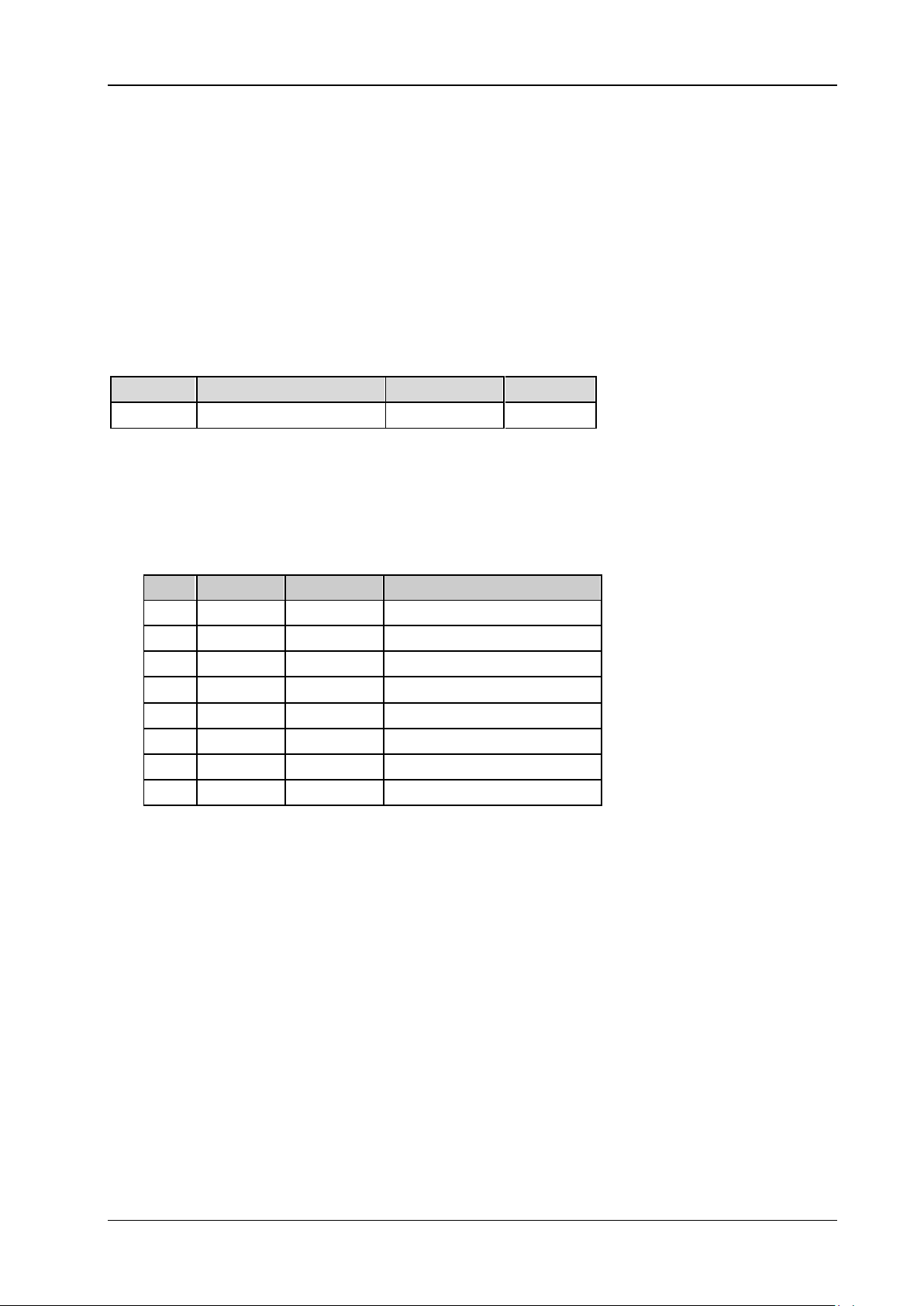
<mask> is the sum of the binary weights (expressed in decimal) of all the bits between bit 0 and bit
7 that have already been set. If the bit has already been set, the corresponding binary bit is 1;
otherwise, it is 0.
Definit ions of the bits in ESE register:
Bit Weights Name Enable
7 128 PON Power On
6 64 URQ User Request
5 32 CME Command Error
4 16 EXE Execution Error
3 8 DDE Dev. Dependent Error
2 4 QYE Query Error
1 2 RQL Request Control
0 1 OPC Operation Complete
Return Format
The query returns an integer between 0 and 255 which equals the sum of the binary weights (expressed
in decimal) of all the bits that have already been set in the register.
For example, the query returns 144 if bit 4 (16 in decimal) and bit 7 (128 in decimal) are enabled.
Example
*ESE 16 /*Bit 4 is enabled*/
*ESE? /*The query retur ns 16*/
DS2000E Programming Guide
Page 22
RIGOL 2 Command System
*ESR?
Syntax
*ESR?
Description
Query the event status register for the standard event register set.
Explanation
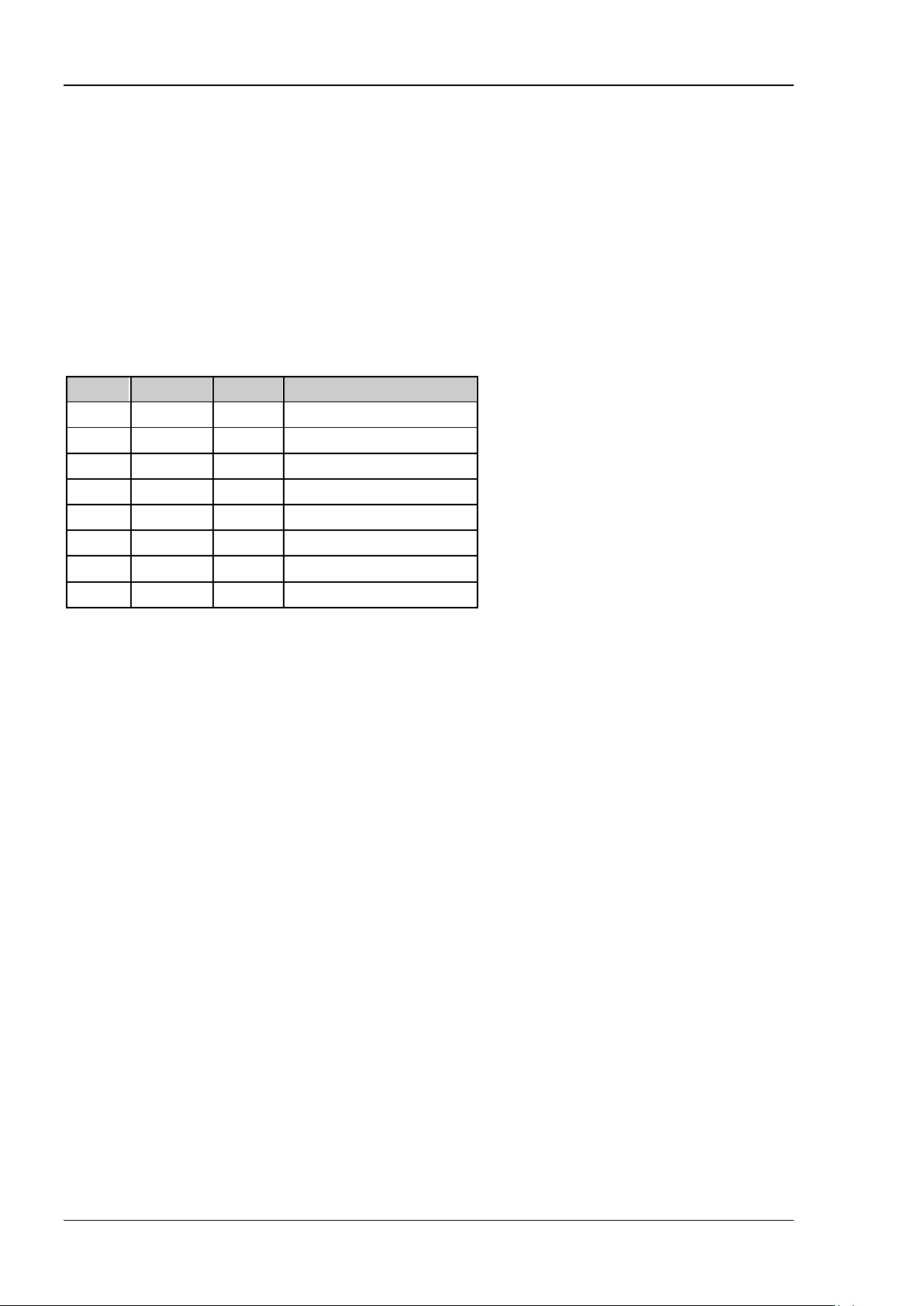
Definit ions of the bits of ESE register:
Bit Weights Name Enable
7 128 PON Power On
6 64 URQ User Request
5 32 CME Command Error
4 16 EXE Execution Error
3 8 DDE Dev. Dependent Error
2 4 QYE Query Error
1 2 RQL Request Control
0 1 OPC Operation Complete
Return Format
The query returns an integer between 0 and 255 which equals the sum of the binary weights (expressed
in decimal) of all the bits that have already been set in the register. For example, the query retu rns 144 if
bit 4 (16 in decimal) and bit 7 (128 in decimal) are enabled.
*IDN?
Syntax
*IDN?
Description
Query the current device information.
Return Format
The query returns R IGOL TECHNOLO GI ES ,<model>,<serial number>,<software version>.
Wherein,
<model> is the model number of the instrument. <serial numb er> is th e serial number of the instrument.
<software version> is the softw are version of the instrument.
2-6 DS2000E Programming Guide
Page 23

2 Command System RIGOL
2-7
*OPC
Syntax
*OPC
*OPC?
Description
Set the Operation Complete bit (bit 0) in the standard event status register to 1 after the current
operation is finished.
Query whether the current operation is finished.
Return Format
The query returns 1 if the current operation is finished ; otherwise, returns 0.
*RST
Syntax
*RST
Description
Restore the instrument to the factory setting.
DS2000E Programming Guide
Page 24
RIGOL 2 Command System
*SRE
Syntax
*SRE <mask>
*SRE?
Description
Set or query the enable register for the state byte register set.
Parameter
Name Type Range Default
<mask> Integer 0 to 255 0
Explanation
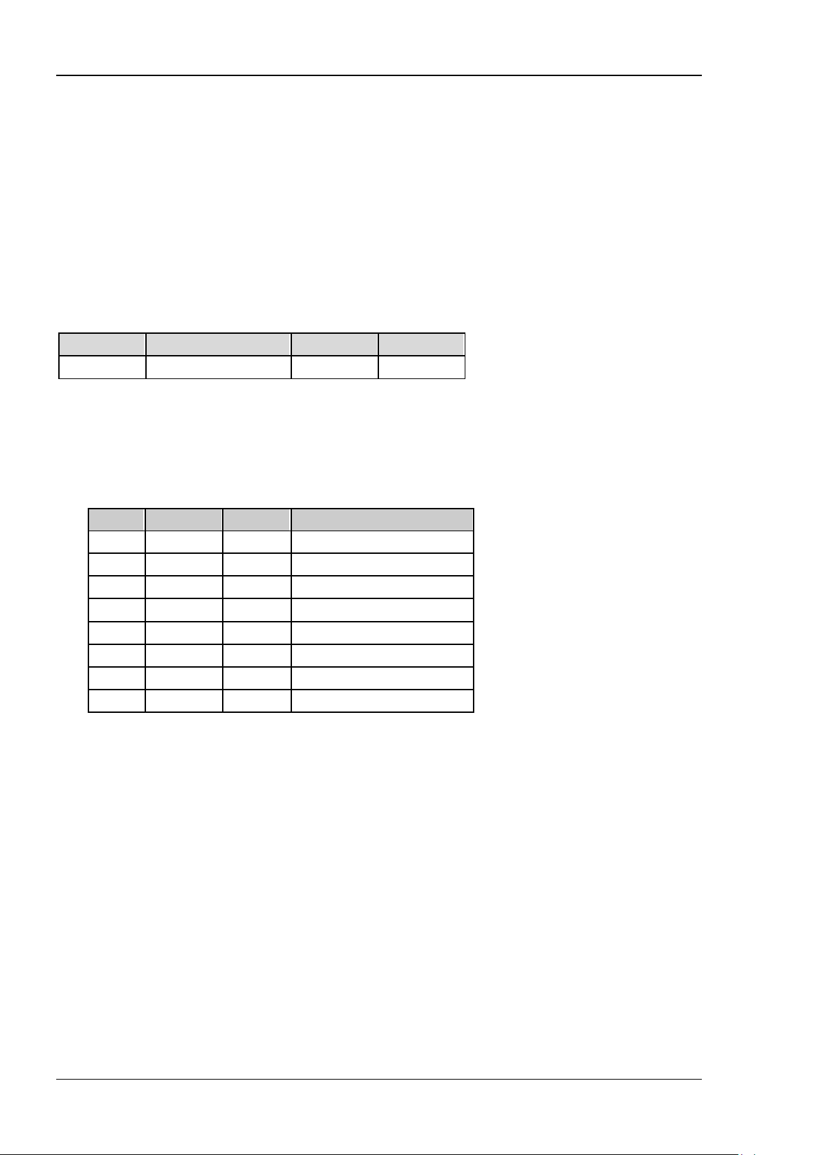
<mask> is the sum of the binary weights (expressed in decimal) of all the bits between bit 0 and bit
7 that have already been set. If the bit has already been set, the corresponding binary bit is 1;
otherwise, it is 0.
Definit ions of the bits of SRE register:
Bit Weights Name Enable
7 128 OPER Operation Status Reg
6 64 -- Not used
5 32 ESB Event Status Bit
4 16 MAV Message Available
3 8 -- Not used
2 4 MSG Message
1 2 USR User
0 1 TRG Trigger
Return Format
The query returns an integer between 0 and 255 which equals the sum of the binary weights (expressed
in decimal) of all the bits that have already been set in the register. For example, the query returns 144 if
bit 4 (16 in decimal) and bit 7 (128 in decimal) are enabled.
Example
*SRE 16 /*Bit 4 is enabled*/
*SRE? /*The query returns 16*/
2-8 DS2000E Programming Guide
Page 25
2 Command System RIGOL
2-9
*STB?
Syntax
*STB?
Description
Query the condition register for the state byte register set.
Explanation
Definit ions of the bits of SRE register:
Bit Weights Name Enable
7 128 OPER Operation Status Reg
6 64 -- Not used
5 32 ESB Event Status Bit
4 16 MAV Message Available
3 8 -- Not used
2 4 MSG Message
1 2 USR User
0 1 TRG Trigger
Return Format
The query returns an integer between 0 and 255 which equals the sum of the binary weights (expressed
in decimal) of all the bits that have already been set in the register. For example, the query retu rns 144 if
bit 4 (16 in decima l) and bit 7 (128 in decimal) are enabled.
Example
*STB? /*The query returns 24 (bit 3 and bit 4 are enabled)*/
DS2000E Programming Guide
Page 26

RIGOL 2 Command System
*TST?
Syntax
*TST?
Description
Perform a self-test and query the result .
Explanation
The self-test result is denoted by a 32-bit binary number. If the corresponding binary bit is 0, the self-test
item passes the test; while 1 indicates a failure. The return value is the decimal integer corresponding to
the binary number.
The self-test item represented by each bit is as shown below. The bit that is not used is always 0.
bit0: system voltage
bit1: analog voltage
bit2: storage system
bit3: digital core
bit4: digital IO
bit9: fan 1
bit10: fan 2
bit12: inlet temperature
bit13: outlet temperature
bit16: real-time clock
Return Format
The query returns a decimal integer.
Example
*TST? /*The query returns 0 (namely the 32 bits of the binary number are all 0*/
2-10 DS2000E Programming Guide
Page 27
2 Command System RIGOL
2-11
:ACQuire Commands
:ACQuire:AVERages
:ACQuire:MDEPth
:ACQuire:SRATe?
:ACQuire:TYPE
:ACQuire:AALias
:ACQuire:AVERages
Syntax
:ACQuire:AVERages <count>
:ACQuire:AVERages?
Description
Set or query the number of averages in average acquisition mode.
Parameter
Name Type Range Default
<count> Discrete 2n (n is an integer from 1 to 13) 2
Explanation
You can use the
oscilloscope averages the waveforms from multiple samples to reduce the random noise on the input
signal and improve the vertical resolution. Greater number of averages can lower the noise and increase
the vertical resolution; while at the same time, it will slower the response of the displayed waveform to
the waveform changes.
Return Format
The query returns the number of averages in average acquisition mode in integer.
:ACQuire:TYPE command to select the average acquisition mode. In this mode, the
DS2000E Programming Guide
Page 28
RIGOL 2 Command System
:ACQuire:MDEPth
Syntax
:ACQuire:MDEPth <mdep>
:ACQuire:MDEPth?
Description
Set or query the memory depth of the oscilloscope; namely the number of waveform points that can be
stored in a single trigger sample. The default unit is pts (points).
Parameter
Name Type Range Default
<mdep> Discrete Refer to Explanation AUTO
Explanation
Non-interweave: AUTO|7000|70000|700000|7000000|28000000 (option).
Return Format
The query returns the memory depth of the oscilloscope in integer.
:ACQuire:SRATe?
Syntax
:ACQuire:SRATe?
Description
Query the current sample rate. The default unit is Sa/s.
Return Format
The query returns the current sample rate in scientific notation. For example, 1.00000e+09; name ly
1.000GSa/s.
2-12 DS2000E Programming Guide
Page 29
2 Command System RIGOL
2-13
:ACQuire:TYPE
Syntax
:ACQuire:TYPE <type>
:ACQuire:TYPE?
Description
Set or query the acquisition mode of the sample.
Parameter
Name Type Range Default
<type> Discrete {NORMal|AVERages|PEAK|HRESolution} NORMal
Explanation
NORMal: the oscilloscope samples the signal at equal time interval. For most of waveforms, this
mode can ensure the optimum display effect.
AVERages: the oscilloscope averages the waveforms from multiple samples to reduce the random
noise on the input signal and increase the vertical resolution. In this mode, you can use
the
:ACQuire:AVERages command to set the number of averages.
PEAK: the oscilloscope samples the maximum and minimum values of the signal within the sample
interval to acquire the envelop of the signal and na r r ow pulses that might be lost. But in this mode,
the display noise is relatively larger.
HRESolution: the oscilloscope averages the neighbouring points of the sampled waveform. This
mode is usually used when the sample rate of the digital converter is greater than the storage rate of
the sample storage.
Return Format
The query returns NORM, AVER, PEAK, or HRES.
DS2000E Programming Guide
Page 30
RIGOL 2 Command System
:ACQuire:AALias
Syntax
:ACQuire:AALias <bool>
:ACQuire:AALias?
Description
Enable or disable the antialiasing function of the oscill o scope; or query the current state of the
antialiasing function of the oscilloscope.
Parameter
Name Type Range Default
<bool> Bool {{1|ON}|{0|OFF}} 0|OFF
Return Format
The query returns 1 or 0.
2-14 DS2000E Programming Guide
Page 31
2 Command System RIGOL
2-15
:BUS<n> Commands
:BUS<n>:MODE
:BUS<n>:DISPlay
:BUS<n>:FORMat
:BUS<n>:EVENt
:BUS<n>:EEXPort
:BUS<n>:DATA?
:BUS<n>:PARallel
:BUS<n>:RS232 (Option)
:BUS<n>:IIC (Option)
:BUS<n>:SPI (Option)
:BUS<n>:CAN (Option)
:BUS<n>:MODE
Syntax
:BUS<n>:MODE <mode>
:BUS<n>:MODE?
Description
Set or query the decoding mode of the specified bus.
Parameter
Name Type Range Default
<n> Discrete {1|2} -<mode> Discrete {PARallel|RS232|IIC|SPI|CAN} PARallel
Explanation
RS232 decoding, I2C decoding, SPI decoding and CAN decoding are options and this command is only
valid when the corresponding options are installed.
Return Format
The query returns PAR, RS232, IIC, SPI, or CA N.
DS2000E Programming Guide
Page 32
RIGOL 2 Command System
:BUS<n>:DISPlay
Syntax
:BUS<n>:DISPlay <bool>
:BUS<n>:DISPlay?
Description
Enable or disable the display of the specified bus; or query the current display status of the specified bus.
Parameter
Name Type Range Default
<n> Discrete {1|2} -<bool> Bool {{1|ON}|{0|OFF}} 0|OFF
Return Format
The query returns 1 or 0.
:BUS<n>:FORMat
Syntax
:BUS<n>:FORMat <form at>
:BUS<n>:FORMat?
Description
Set or query the display format of the specified bus.
Parameter
Name Type Range Default
<n> Discrete {1|2} -<format> Discrete {HEX|DEC|BIN|ASCii} HEX
Explanation
HEX: hexadecimal;
DEC: decimal;
BIN: binary;
ASCii: ASCII.
Return Format
The query returns HEX, DEC, BIN, or ASC.
2-16 DS2000E Programming Guide
Page 33
2 Command System RIGOL
2-17
:BUS<n>:EVENt
Syntax
:BUS<n>:EVENt <bool>
:BUS<n>:EVENt?
Description
Enable or disable the even t table of the specified bus; or query the current status of the event table of the
specified bus.
Parameter
Name Type Range Default
<n> Discrete {1|2} -<bool> Bool {{1|ON}|{0|OFF}} 0|OFF
Explanation
This command is only available when t he displayof the specified bus is enabled (
Return Format
The query returns 1 or 0.
:BUS<n>:DISPlay).
:BUS<n>:EEXPort
Syntax
:BUS<n>:EEXPort
Description
Export the event table of the specified bus.
Parameter
Name Type Range Default
<n> Discrete {1|2} --
Explanation
The data list can be exported to an external USB storage device in CSV f ormat if an USB storage device is
currently connecte d.
DS2000E Programming Guide
Page 34
RIGOL 2 Command System
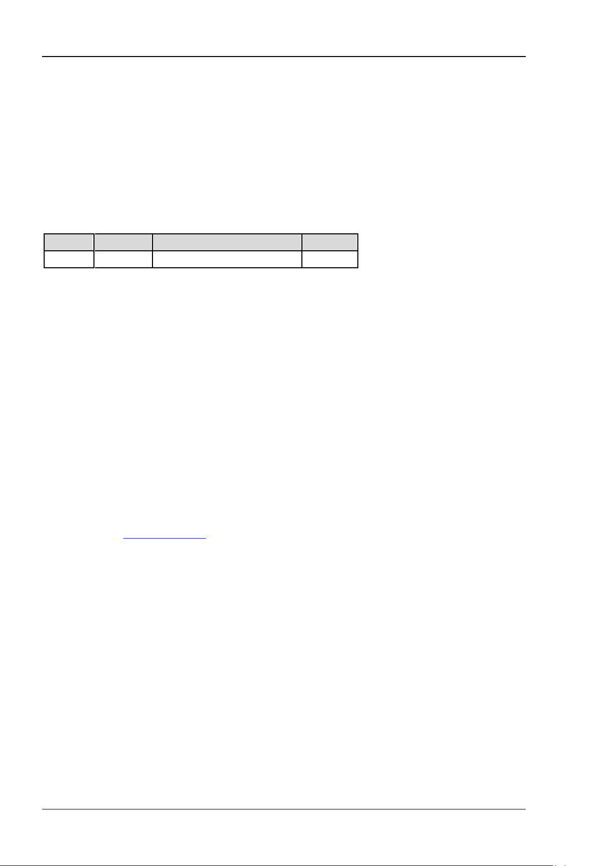
:BUS<n>:DATA?
Syntax
:BUS<n>:DATA?
Description
Read the decoding event table data.
Parameter
Name Type Range Default
<n> Discrete {1|2} --
Return Format
The query returns the decoding event table data in the following format.
#9000000141RS232
Time,TX,TX ERR,
-6.1352322E-03,*,,
-4.0554402E-03,R,,
-1.9756482E-03,I,,
1.0414385E-04,G,,
2.1839839E-03,O,,
4.2637759E-03,L,,
Wherein, #9000000141 is the TMC data block header following which is the data in the event table. The
figure behind #9 denotes the number of bytes of th e effective data. RS232 deno tes the decoding mode (it
can also be Parallel, I2C, SPI or CAN). The data are se parated by commas and will be displayed in
different lines automatically according to the lines in the decoding table. The data value is related to the
specified format (
Note: You can save the data (except the TMC data block header and the decoding type; for example,
#9000000141RS232) as a *.csv file and view the data in table form.
:BUS<n>:FORMat).
2-18 DS2000E Programming Guide
Page 35
2 Command System RIGOL
2-19
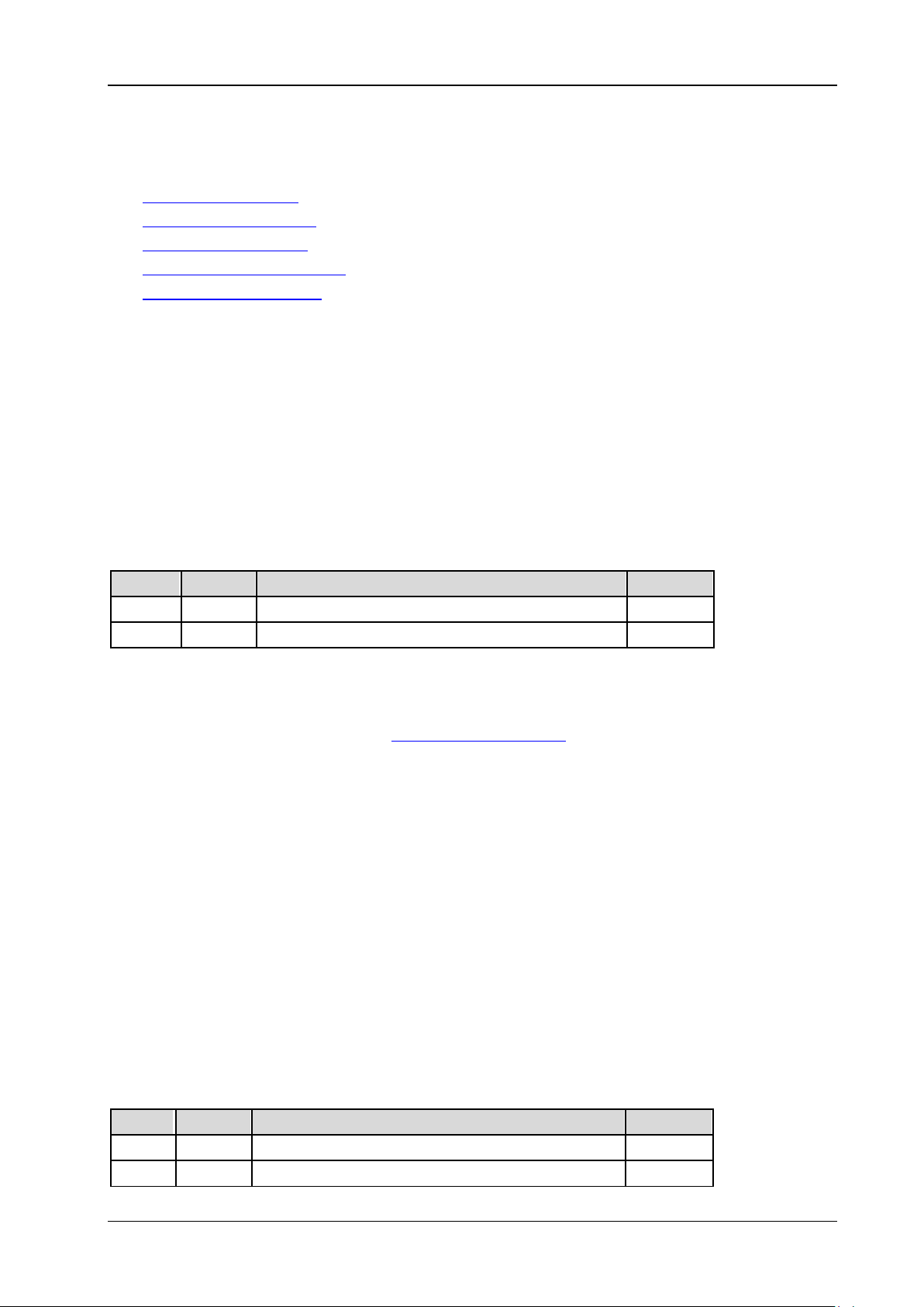
:BUS<n>:PARallel
:BUS<n>:PARallel:CLK
:BUS<n>:PARallel:SLOPe
:BUS<n>:PARallel:BSET
:BUS<n>:PARallel:THReshold
:BUS<n>:PARallel:OFFSet
:BUS<n>:PARallel:CLK
Syntax
:BUS<n>:PARallel:CLK <sour>
:BUS<n>:PARallel:CLK?
Description
Set or query the clock channel source of parallel decoding on the specified bus.
Parameter
Name Type Range Default
<n> Discrete {1|2} -<sour> Discrete {CHANnel1|CHANnel2|OFF} CHANnel1
Explanation
When OFF is selected, no clock channel is set and the oscilloscope samples data once the channel data
jumps. At this point, the edge set by the
Return Format
The query returns CHAN1, CHAN2, or OFF.
:BUS<n>:PARallel:SLOPe
Syntax
:BUS<n>:PARallel:SLOPe <pos>
:BUS<n>:PARallel:SLOPe?
Description
Set or query the edge of the clock on which the oscilloscope samples the channel data.
Parameter
Name Type Range Default
<n> Discrete {1|2} -<pos> Discrete {POSitive|NEGative|BOTH} POSitive
:BUS<n>:PARallel:SLOPe command can be ignored.
DS2000E Programming Guide
Page 36
RIGOL 2 Command System
Explanation
POSitive: rising edge
NEGative: falling edge
BOTH: rising/falling edge
When no clock cha nnel is set (refer to the
samples data once the channel data jumps and the edge set by this command will be ignored.
Return Format
The query returns POS, NEG, or BOTH
.
:BUS<n>:PARallel:CLK command), the oscilloscope
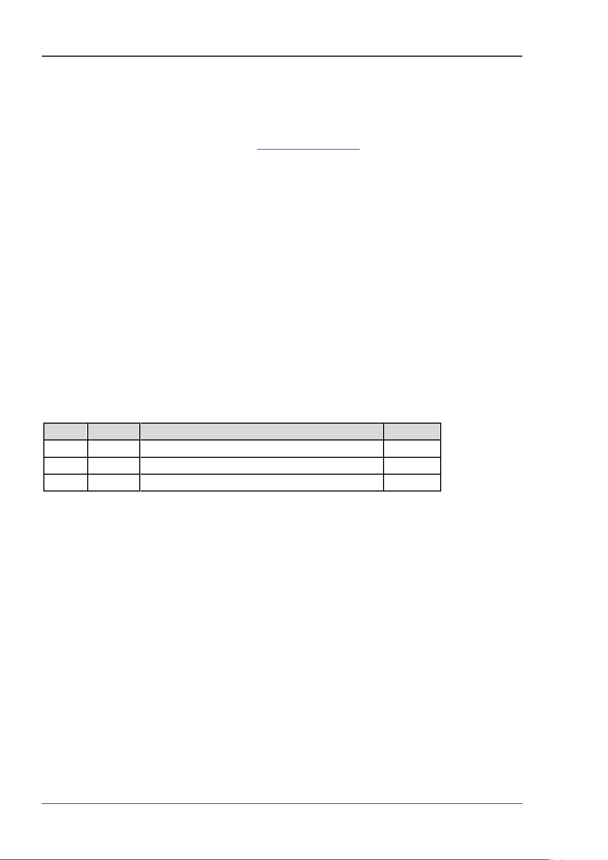
:BUS<n>:PARallel:BSET
Syntax
:BUS<n>:PARallel:BSET <b0>,<b1>
:BUS<n>:PARallel:BSET?
Description
Set the data width of parallel decoding on the specified bus and the channel source for each bit; or query
the channel source of each bit.
Parameter
Name Type Range Default
<n> Discrete {1|2} -<b0> Discrete {CHANnel1|CHANnel2} CHANnel1
<b1> Discrete {CHANnel1|CHANnel2} CHANnel2
Explanation
This command sets the bus data width and the setting sequence of the bits is LSB. For example, when the
parameter is set to CHAN2,CHAN1, the bus data width is set to 2, bit 0 is CHAN2 and bit 1 is CHAN1.
Return Format
The query returns the channel source of each bit in the current data channel. The number of the channel
sources is determined by the current data width and multiple channels are separated by commas.
Example
:BUS1:PARallel:BSET CHAN nel1,CHANnel2
/*Set the data width to 2 and the channel sources of the bits are CH1 and
CH2 respectively*/
:BUS1:PARallel:BSET? /*The query returns CHAN1,CHAN2*/
2-20 DS2000E Programming Guide
Page 37
2 Command System RIGOL
2-21
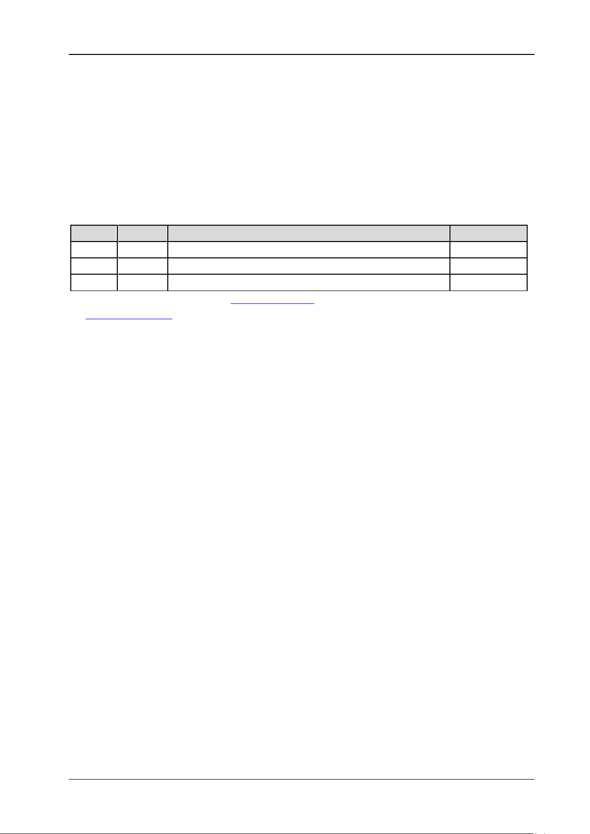
:BUS<n>:PARallel:THReshold
Syntax
:BUS<n>:PARallel:THReshold <sour>,<thre>
:BUS<n>:PARallel:THReshold? <sour>
Description
Set or query the analog channel threshold of parallel decoding on the specified bus.
Parameter
Name Type Range Default
<n> Discrete {1|2} -<sour> Discrete {CHANnel1|CHANnel2} -<thre> Real (-5 x VerticalScale - OFFSet) to (+5 x VerticalScale - OFFSet) 0
Note: For the VerticalScale, refer to the :CHANnel<n>:SCALe command. For the OFFSet, refer to
the
:CHANnel<n>:OFFSet command.
Return Format
The query returns the analog channel threshold of parallel decoding on the specified bus in scientific
notation.
DS2000E Programming Guide
Page 38
RIGOL 2 Command System
[1]
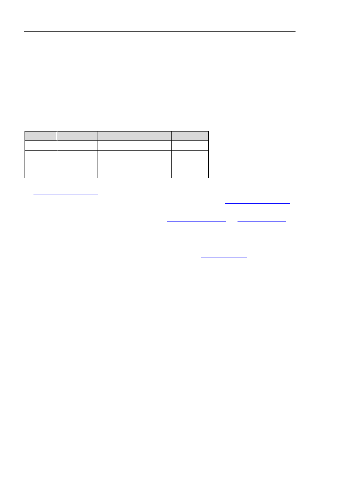
:BUS<n>:PARallel:OFFSet
Syntax
:BUS<n>:PARallel:OFFSet <val>
:BUS<n>:PARallel:OFFSet?
Description
Set or query the vertical offset of parallel decoding on the specified bus.
Parameter
Name Type Range Default
<n> Discrete {1|2} --
Normal
<val> Integer
Statistic
Half screen
[1]
Note
the
Note
command).
Note
commands).
: The screen display is normal and the statistic function is not enabled (refer to
:MEASure:STATistic:DISPlay command).
[2]
: The screen display is normal and the statistic function is enabled (refer to the :MEASure:STATistic:DISPlay
[3]
: The screen is divided into two windows (refer to the :TIMebase:DELay:ENABle and :CALCulate:FFT:SPLit
Explanation
Before using this command, enable the bus display (refer to the
When the data line is located in the middle of the screen, <val> is 0; when it is located above the
middle of the screen, <val> is positive; when it is located below the middle of the screen, <val> is
negative.
Return Format
The query returns t he ve rt i ca l offset of parallel decoding on the specified bus in integer.
: -166 to 148
[2]
: -163 to 143
[3]
: -103 to 52
0
:BUS<n>:DISPlay command).
2-22 DS2000E Programming Guide
Page 39
2 Command System RIGOL
2-23
:BUS<n>:RS232 (Option)
:BUS<n>:RS232:TX
:BUS<n>:RS232:RX
:BUS<n>:RS232:POLarity
:BUS<n>:RS232:ENDian
:BUS<n>:RS232:BAUD
:BUS<n>:RS232:BUSer
:BUS<n>:RS232:DBITs
:BUS<n>:RS232:SBITs
:BUS<n>:RS232:PARity
:BUS<n>:RS232:PACKet
:BUS<n>:RS232:PEND
:BUS<n>:RS232:TTHReshold
:BUS<n>:RS232:RTHReshold
:BUS<n>:RS232:OFFSet
:BUS<n>:RS232:TX
Syntax
:BUS<n>:RS232 : TX <so urc e >
:BUS<n>:RS232:TX?
Description
Set or query the TX channel source of RS232 decoding on the specified bus.
Parameter
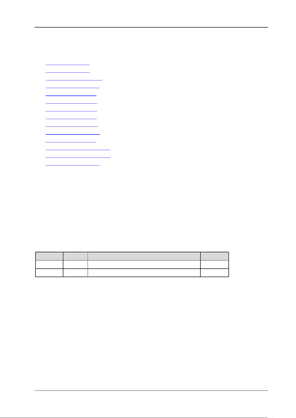
Name Type Range Default
<n> Discrete {1|2} -<source> Discrete {CHANnel1|CHANnel2|OFF} CHANnel1
Explanation
When OFF is selected, no TX channel source will be set. The TX channel source and RX channel source
cannot both be set to OFF.
Return Format
The query returns CHAN1, CHAN2, or OFF.
DS2000E Programming Guide
Page 40
RIGOL 2 Command System
:BUS<n>:RS232:RX
Syntax
:BUS<n>:RS232:RX <source>
:BUS<n>:RS232:RX?
Description
Set or query the RX channel source of RS232 decoding on the specified bus.
Parameter
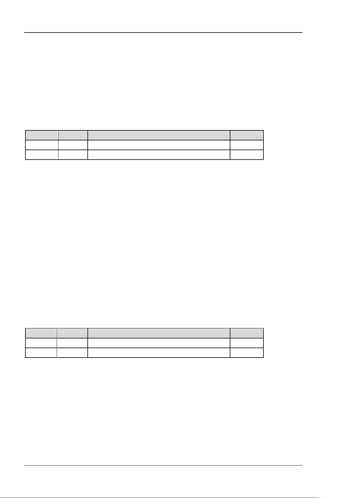
Name Type Range Default
<n> Discrete {1|2} -<source> Discrete {CHANnel1|CHANnel2|OFF} OFF
Explanation
When OFF is selected, no RX channel source will be set. The TX channel source and RX channel source
cannot both be set to OFF.
Return Format
The query returns CHAN1, CHAN2, or OFF.
:BUS<n>:RS232:POLarity
Syntax
:BUS<n>:RS232 :PO La rity <pol>
:BUS<n>:RS232:POLarity?
Description
Set or query the polarity of RS232 decod ing on the specified bus.
Parameter
Name Type Range Default
<n> Discrete {1|2} -<pol> Discrete {POSitive|NEGative} NEGative
Explanation
The RS232 standard uses negative logic; namely high level is 0 and low level is 1. Therefore, when <pol>
is set to NEGative, the polarity is set to negative logic (namely "Normal" polarity); when <pol> is set to
POSitive, the polarity is set to positive polarity (namely "Invert" polarity).
Return Format
The query returns POS or NEG.
2-24 DS2000E Programming Guide
Page 41
2 Command System RIGOL
2-25
:BUS<n>:RS232:ENDian
Syntax
:BUS<n>:RS232 :EN Di an < endian>
:BUS<n>:RS232:ENDian?
Description
Set or query the endian of data transmission of RS232 decoding on the specified bus.
Parameter
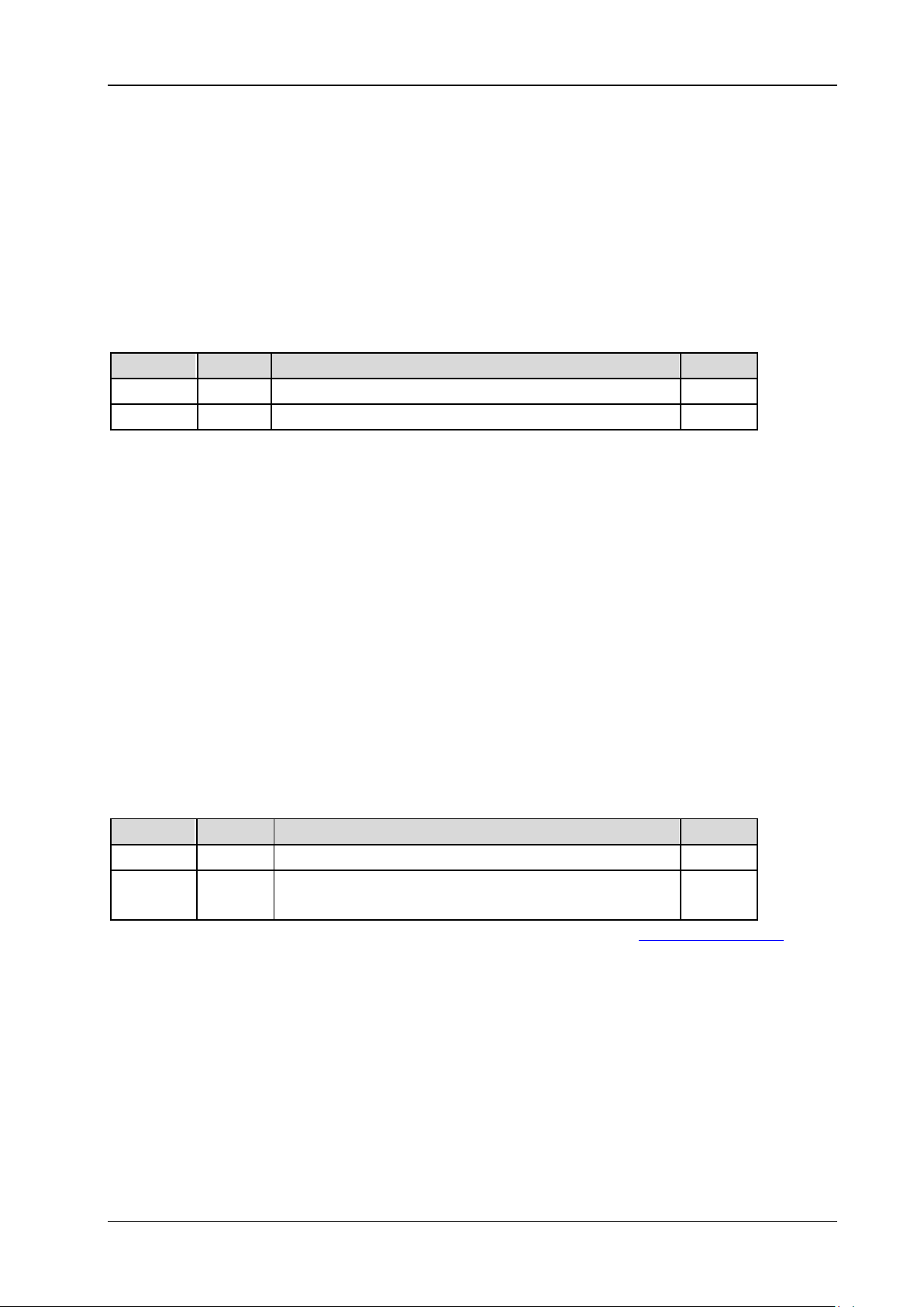
Name Type Range Default
<n> Discrete {1|2} -<endian> Discrete {MSB|LSB} LSB
Return Format
The query returns MSB or LSB.
:BUS<n>:RS232:BAUD
Syntax
:BUS<n>:RS232 :BAUD <baud>
:BUS<n>:RS232:BAUD?
Description
Set or query the baud rate of data transmission of RS232 decoding on the specified bus. The default unit
is bps.
Parameter
Name Type Range Default
<n> Discrete {1|2} -<baud> Discrete
Note: When the baud rate is set to USER, you can set a specific baud rate using the :BUS<n>:RS232:BUSer
command.
Return Format
The query returns the baud rate of data transmission of RS232 decoding on the specified bus in integer or
returns USER.
{2400|4800|9600|19200|38400|57600|115200|
230400|460800|921600|1000000|USER}
9600
DS2000E Programming Guide
Page 42
RIGOL 2 Command System
:BUS<n>:RS232:BUSer
Syntax
:BUS<n>:RS232:BUSer <baud>
:BUS<n>:RS232:BUSer?
Description
Set or q uery the user -defined baud rate of data transmission of RS232 decoding on the specified bus. The
default unit is bps.
Parameter
Name Type Range Default
<n> Discrete {1|2} -<baud> Integer 110 to 20000000 9600
Return Format
The query returns the user-defined baud rate of data transmission of RS232 decoding o n the specified
bus in integer.
:BUS<n>:RS232:DBITs
Syntax
:BUS<n>:RS232:DBITs <bits>
:BUS<n>:RS232:DBITs?
Description
Set or query the number of bits of data of RS232 decoding on the specified bus.
Parameter
Name Type Range Default
<n> Discrete {1|2} -<bits> Discrete {5|6|7|8|9} 8
Return Format
The query returns 5, 6, 7, 8, or 9.
2-26 DS2000E Programming Guide
Page 43
2 Command System RIGOL
2-27
:BUS<n>:RS232:SBITs
Syntax
:BUS<n>:RS232:SBITs <stop bits>
:BUS<n>:RS232:SBITs?
Description
Set or query the stop bit after each frame of data of RS232 decoding on the specified bus.
Parameter
Name Type Range Default
<n> Discrete {1|2} -<stop bits> Discrete {1|1.5|2} 1
Return Format
The query returns 1, 1.5, or 2.
:BUS<n>:RS232:PARity
Syntax
:BUS<n>:RS232 :PA Ri ty <parity>
:BUS<n>:RS232:PARity?
Description
Set or query the even-odd check mode of data transmission of RS232 decoding on the specified bus.
Parameter
Name Type Range Default
<n> Discrete {1|2} -<parity> Discrete {NONE|ODD|EVEN} NONE
Return Format
The query returns NONE, ODD, or EVEN.
DS2000E Programming Guide
Page 44
RIGOL 2 Command System
:BUS<n>:RS232:PACKet
Syntax
:BUS<n>:RS232:PACKet <bool>
:BUS<n>:RS232:PACKet?
Description
Enable or disable the packet end in data transmission; or query the current status of the packet end in
data transmission.
Parameter
Name Type Range Default
<n> Discrete {1|2} -<bool> Bool {{1|ON}|{0|OFF}} 0|OFF
Explanation
When the packet end is enabled, several data blocks are combined according to the packet end.
Return Format
The query returns 1 or 0.
:BUS<n>:RS232:PEND
Syntax
:BUS<n>:RS232:PEND <package end>
:BUS<n>:RS232:PEND?
Description
Set or query the packet end of data transmission.
Parameter
Name Type Range Default
<n> Discrete {1|2} -<package end> Discrete {NULL|LF|CR|SP|FF} NULL
Explanation
The hexadecimal numbers corresponding to the parameters are as follows.
NULL: 00 LF: 0A CR: 0D SP: 20 FF: FF
Return Format
The query returns NULL, LF, CR, SP, or FF.
2-28 DS2000E Programming Guide
Page 45
2 Command System RIGOL
2-29
:BUS<n>:RS232:TTHReshold
Syntax
:BUS<n>:RS232:TTHReshold <tthre>
:BUS<n>:RS232:TTHReshold?
Description
Set or query
the TX channel threshold of R232 decoding on the spe cified bus.
Parameter
Name Type Range Default
<n> Discrete {1|2} -<tthre> Real (-5 x VerticalScale - OFFSet) to (+5 x VerticalScale - OFFSet) 0
Note: For the VerticalScale, refer to the :CHANnel<n>:SCALe command. For the OFFSet, refer to
the
:CHANnel<n>:OFFSet command.
Explanation
This command is only available when the TX channel source is CH1 or CH2.
Return Format
The query returns the TX channel threshold of R232 decoding on the specified bus in scientific notation.
:BUS<n>:RS232:RTHReshold
Syntax
:BUS<n>:RS232:RTHReshold <rthre>
:BUS<n>:RS232:RTHReshold?
Description
Set or query
Parameter
Name Type Range Default
<n> Discrete {1|2} -<rthre> Real (-5 x VerticalScale - OFFSet) to (+5 x VerticalScale - OFFSet) 0
Note: For the VerticalScale, refer to the :CHANnel<n>:SCALe command. For the OFFSet, refer to
the
:CHANnel<n>:OFFSet command.
Explanation
This command is only available when the RX channel source is CH1 or CH2.
Return Format
The query returns the RX channel threshold of R232 decoding on the specified bus in scientific notation.
the RX channel threshold of R232 decoding on the specified bus.
DS2000E Programming Guide
Page 46
RIGOL 2 Command System
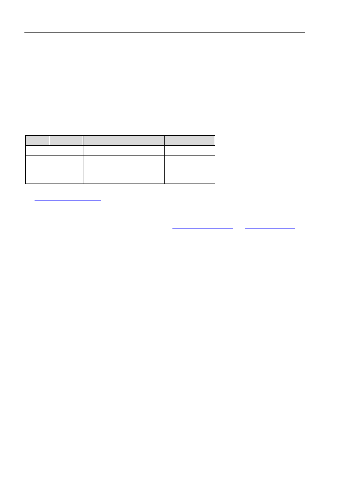
[1]
:BUS<n>:RS232:OFFSet
Syntax
:BUS<n>:RS232 :OF FSe t <va l>
:BUS<n>:RS232:OFFSet?
Description
Set or query the vertical offset of RS232 decoding on the specified bus.
Parameter
Name Type Range Default
<n> Discrete {1|2} --
Normal
<val> Integer
Statistic
Half screen
[1]
Note
the
Note
command).
Note
commands).
: The screen display is normal and the statistic function is not enabled (refer to
:MEASure:STATistic:DISPlay command).
[2]
: The screen display is normal and the statistic function is enabled (refer to the :MEASure:STATistic:DISPlay
[3]
: The screen is divided into two windows (refer to the :TIMebase:DELay:ENABle and :CALCulate:FFT:SPLit
Explanation
Before using this command, enable the bus display (refer to the
When the data line is located in the m iddle of the screen, <val> is 0; when it is located above the
middle of the screen, <val> is positive; when it is locate d below the m iddle o f t he screen, <val> is
negative.
Return Format
The query returns the vertical offset of RS232 decoding on the specified bus in integer.
: -166 to 148
[2]
: -163 to 143
[3]
: -103 to 52
0
:BUS<n>:DISPlay command).
2-30 DS2000E Programming Guide
Page 47
2 Command System RIGOL
2-31
:BUS<n>:IIC (Option)
:BUS<n>:IIC:SCLK:SOURce
:BUS<n>:IIC:SCLK:THReshold
:BUS<n>:IIC:SDA:SOURce
:BUS<n>:IIC:SDA:THReshold
:BUS<n>:IIC:OFFSet
:BUS<n>:IIC:SCLK:SOURce
Syntax
:BUS<n>:IIC:SCLK:SOURce <sour>
:BUS<n>:IIC:SCLK:SOURce?
Description
Set or query the clock channel source of I2C decoding on the specified bus.
Parameter
Name Type Range Default
<n> Discrete {1|2} -<sour> Discrete {CHANnel1|CHANnel2} CHANnel1
Return Format
The query returns CHAN1 or CHAN2.
:BUS<n>:IIC:SCLK:THReshold
Syntax
:BUS<n>:IIC:SCLK:THReshold <thre>
:BUS<n>:IIC:SCLK:THReshold?
Description
Set or query the clock channel thres hold of I2C decoding on the specified bus.
Parameter
Name Type Range Default
<n> Discrete {1|2} -<thre> Real (-5 x VerticalScale - OFFSet) to (+5 x VerticalScale - OFFSet) 0
Note: For the VerticalScale, refer to the :CHANnel<n>:SCALe command. For the OFFSet, refer to
the
:CHANnel<n>:OFFSet command.
DS2000E Programming Guide
Page 48
RIGOL 2 Command System
Return Format
The query returns the clock channel threshold of I2C decoding on the specified bus in scientific notation.
:BUS<n>:IIC:SDA:SOURce
Syntax
:BUS<n>:IIC:S DA :SO UR ce <s o ur>
:BUS<n>:IIC:SDA:SOURce?
Description
Set or query the data channel source of I2C decoding on the specified b us.
Parameter
Name Type Range Default
<n> Discrete {1|2} -<sour> Discrete {CHANnel1|CHANnel2} CHANnel2
Return Format
The query returns CHAN1 or CHAN2.
:BUS<n>:IIC:SDA:THReshold
Syntax
:BUS<n>:IIC:SDA:THReshold <thre>
:BUS<n>:IIC:SDA:THReshold?
Description
Set or query the data channel threshold of I2C decoding on the specified bus.
Parameter
Name Type Range Default
<n> Discrete {1|2} -<thre> Real (-5 x VerticalScale - OFFSet) to (+5 x VerticalScale - OFFSet) 0
Note: For the VerticalScale, refer to the :CHANnel<n>:SCALe command. For the OFFSet, refer to
the
:CHANnel<n>:OFFSet command.
Return Format
The query returns the data channel thres hold of I2C decoding on the specified bus in scientific notation.
2-32 DS2000E Programming Guide
Page 49
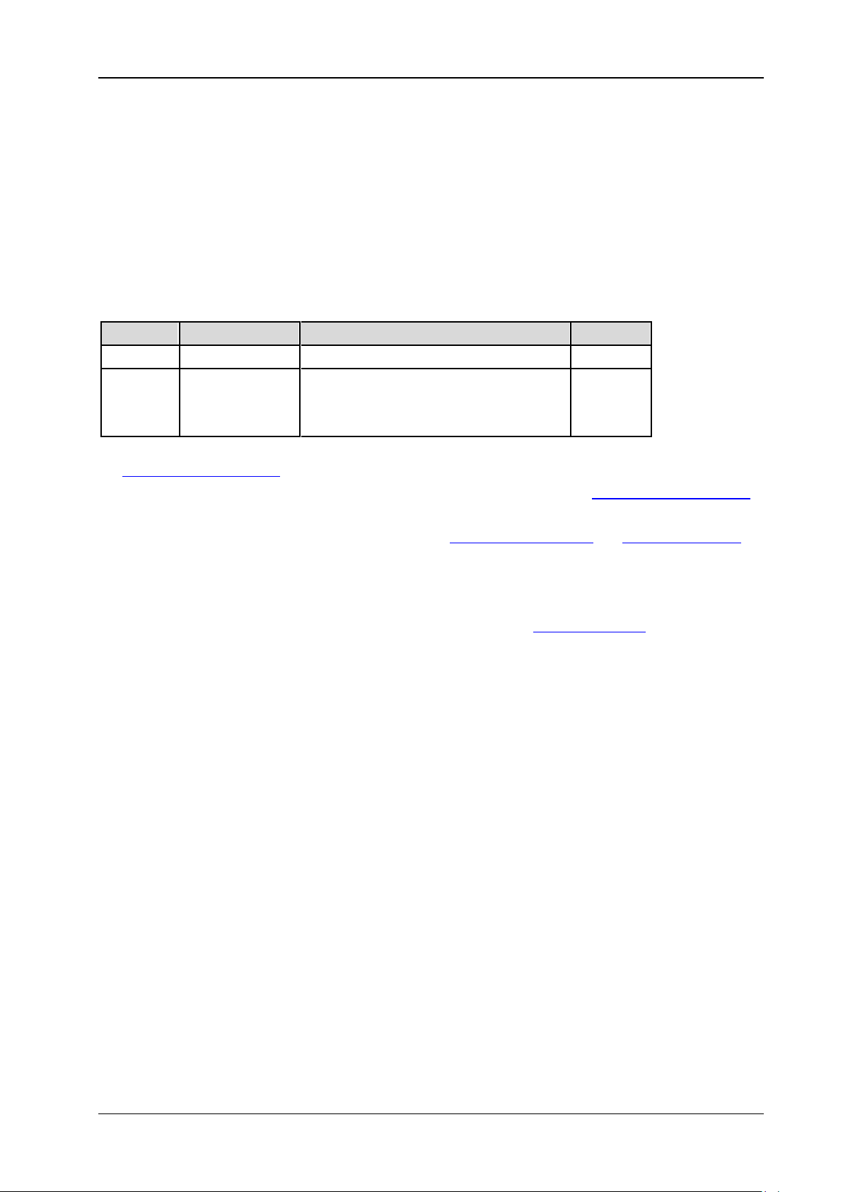
2 Command System RIGOL
2-33
[1]
:BUS<n>:IIC:OFFSet
Syntax
:BUS<n>:IIC:OFF Set <val>
:BUS<n>:IIC:OFFSet?
Description
Set or query the vertical offset of I2C decoding on the specified bus.
Parameter
Name Type Range Default
<n> Discrete {1|2} --
Normal
<val> Integer
Statistic
Half screen
[1]
Note
the
Note
command).
Note
commands).
: The screen display is normal and the statistic function is not enabled (refer to
:MEASure:STATistic:DISPlay command).
[2]
: The screen display is normal and the statistic function is enabled (refer to the :MEASure:STATistic:DISPlay
[3]
: The screen is divided into two windows (refer to the :TIMebase:DELay:ENABle and :CALCulate:FFT:SPLit
Explanation
Before using this command, enable the bus display (refer to the
When the data line is located in the middle of the screen, <val> is 0; when it is l ocated above the
middle of the screen, <val> is positive; when it is located be low the middle of the screen, <val> is
negative.
Return Format
The query returns the vertical offset of I2C decoding on the specified bus in integer.
: -166 to 148
[2]
: -163 to 143
[3]
: -103 to 52
0
:BUS<n>:DISPlay command).
DS2000E Programming Guide
Page 50
RIGOL 2 Command System
:BUS<n>:SPI (Option)
:BUS<n>:SPI:SCLK:SOURce
:BUS<n>:SPI:SCLK:SLOPe
:BUS<n>:SPI:SCLK:THReshold
:BUS<n>:SPI:SDA:SOURce
:BUS<n>:SPI:SDA:POLarity
:BUS<n>:SPI:SDA:THReshold
:BUS<n>:SPI:DBITs
:BUS<n>:SPI:ENDian
:BUS<n>:SPI:OFFSet
:BUS<n>:SPI:TIMeout:TIME
:BUS<n>:SPI:SCLK:SOURce
Syntax
:BUS<n>:SPI:SCLK:SOURce <sour>
:BUS<n>:SPI:SCLK:SOURce?
Description
Set or query the clock channel s ource of SPI decoding on the specified bus.
Parameter
Name Type Range Default
<n> Discrete {1|2} -<sour> Discrete {CHANnel1|CHANnel2} CHANnel1
Return Format
The query returns CHAN1 or CHAN2.
2-34 DS2000E Programming Guide
Page 51
2 Command System RIGOL
2-35
:BUS<n>:SPI:SCLK:SLOPe
Syntax
:BUS<n>:SPI:SC LK : SLOP e <pos>
:BUS<n>:SPI:SCLK:SLOPe?
Description
Set or query the clock edge type of SPI decoding on the specified bus.
Parameter
Name Type Range Default
<n> Discrete {1|2} -<pos> Discrete {POSitive|NEGative} POSitive
Return Format
The query returns POS or NEG.
:BUS<n>:SPI:SCLK:THReshold
Syntax
:BUS<n>:SPI:SCLK :THR e s hold <t hre>
:BUS<n>:SPI:SCLK:THReshold?
Description
Set or query the clock channel thres hold of SPI decoding on the specified bus.
Parameter
Name Type Range Default
<n> Discrete {1|2} -<thre> Real (-5 x VerticalScale - OFFSet) to (+5 x VerticalScale - OFFSet) 0
Note: For the VerticalScale, refer to the :CHANnel<n>:SCALe command. For the OFFSet, refer to
the
:CHANnel<n>:OFFSet command.
Return Format
The query returns the clock channel threshold of SPI decoding on the specified bus in scientific notation.
DS2000E Programming Guide
Page 52
RIGOL 2 Command System
:BUS<n>:SPI:SDA:SOURce
Syntax
:BUS<n>:SPI:SDA:SOURce <s our>
:BUS<n>:SPI:SDA:SOURce?
Description
Set or query the data channel source of SPI decoding on the specified bus.
Parameter
Name Type Range Default
<n> Discrete {1|2} -<sour> Discrete {CHANnel1|CHANnel2} CHANnel2
Return Format
The query returns CHAN1 or CHAN2.
:BUS<n>:SPI:SDA:POLarity
Syntax
:BUS<n>:SPI:SDA:POLarity <pos>
:BUS<n>:SPI:SDA:POLarity?
Description
Set or query the pol arity of the SDA data line of SPI decoding on the specified bus.
Parameter
Name Type Range Default
<n> Discrete {1|2} -<pos> Discrete {HIGH|LOW} HIGH
Explanation
HIGH: low level is 0; high le vel is 1. LOW: high level is 0; low level is 1.
Return Format
The query returns HIGH or LOW.
2-36 DS2000E Programming Guide
Page 53
2 Command System RIGOL
2-37
:BUS<n>:SPI:SDA:THReshold
Syntax
:BUS<n>:SPI:SDA:THReshold <thre>
:BUS<n>:SPI:SDA:THReshold?
Description
Set or query the data channel threshold of SPI decoding on the specified bus.
Parameter
Name Type Range Default
<n> Discrete {1|2} -<thre> Real (-5 x VerticalScale - OFFSet) to (+5 x VerticalScale - OFFSet) 0
Note: For the VerticalScale, refer to the :CHANnel<n>:SCALe command. For the OFFSet, refer to
the
:CHANnel<n>:OFFSet command.
Return Format
The query returns the data channel threshold of SPI decoding on the specified bus in scientific notation.
:BUS<n>:SPI:DBITs
Syntax
:BUS<n>:SPI:DBITs <width>
:BUS<n>:SPI:DBITs?
Description
Set or query the number o f bits of data of SPI decoding on the specified bus.
Parameter
Name Type Range Default
<n> Discrete {1|2} -<width> Integer 4 to 32 8
Return Format
The query returns an integer between 4 and 32.
DS2000E Programming Guide
Page 54
RIGOL 2 Command System
[1]
:BUS<n>:SPI:ENDian
Syntax
:BUS<n>:SPI:EN Dian <endian>
:BUS<n>:SPI:ENDian?
Description
Set or query the endian of data transmission of SPI decoding on the specified bus.
Parameter
Name Type Range Default
<n> Discrete {1|2} -<endian> Discrete {MSB|LSB} MSB
Return Format
The query returns MSB or LSB.
:BUS<n>:SPI:OFFSet
Syntax
:BUS<n>:SPI:OF FSet <val>
:BUS<n>:SPI:OFFSet?
Description
Set or query the vertical offset of SPI decoding on the specified bus.
Parameter
Name Type Range Default
<n> Discrete {1|2} --
Normal
<val> Integer
Statistic
Half screen
[1]
Note
the
Note
command).
Note
commands).
: The screen display is normal and the statistic function is not enabled (refer to
:MEASure:STATistic:DISPlay command).
[2]
: The screen display is normal and the statistic function is enabled (refer to the :MEASure:STATistic:DISPlay
[3]
: The screen is divided into two windows (refer to the :TIMebase:DELay:ENABle and :CALCulate:FFT:SPLit
Explanation
Before using this command, enable the bus display (refer to the
When the data line is locat ed in the middle of the screen, <val> is 0; when it is located above the
middle of the screen, <val> is positi ve; when it is loc ate d below the m iddle o f the screen, <val> is
negative.
: -166 to 148
[2]
: -163 to 143
[3]
: -103 to 52
0
:BUS<n>:DISPlay command).
2-38 DS2000E Programming Guide
Page 55
2 Command System RIGOL
2-39
Return Format
The query returns the vertical offset of SPI decoding on the specified bus in integer.
:BUS<n>:SPI:TIMeout:TIME
Syntax
:BUS<n>:SPI:TIMeout:TIME <val>
:BUS<n>:SPI:TIMeout:TIME?
Description
Set or query the timeout time of SPI decoding on the specified bus. The default unit is s.
Parameter
Name Type Range Default
<n> Discrete {1|2} -<val> Real 100ns to 1s 1us
Return Format
The query returns the timeout time of SPI decoding on the specified bus in scientific notation.
DS2000E Programming Guide
Page 56
RIGOL 2 Command System
:BUS<n>:CAN (Option)
:BUS<n>:CAN:SOURce
:BUS<n>:CAN:STYPe
:BUS<n>:CAN:BAUD
:BUS<n>:CAN:BUSer
:BUS<n>:CAN:SPOint
:BUS<n>:CAN:THReshold
:BUS<n>:CAN:OFFSet
:BUS<n>:CAN:SOURce
Syntax
:BUS<n>:CAN:SOURce <sour>
:BUS<n>:CAN:SOURce?
Description
Set or query the channel source of CAN decoding on the specified bus.
Parameter
Name Type Range Default
<n> Discrete {1|2} -<sour> Discrete {CHANnel1|CHANnel2} CHANnel1
Return Format
The query returns CHAN1 or CHAN2.
:BUS<n>:CAN:STYPe
Syntax
:BUS<n>:CAN:STYPe <stype>
:BUS<n>:CAN:STYPe?
Description
Set or query the signal type of CAN decoding on the specified bus.
Parameter
Name Type Range Default
<n> Discrete {1|2} -<stype> Discrete {TX|RX|CANH|CANL|DIFFerential} RX
Return Format
The query returns TX, RX, CANH, CANL, or DIFF.
2-40 DS2000E Programming Guide
Page 57
2 Command System RIGOL
2-41
:BUS<n>:CAN:BAUD
Syntax
:BUS<n>:CAN:BAUD <baud>
:BUS<n>:CAN:BAUD?
Description
Set or query the signal rate of CAN decoding on the specified bus. The default unit is b/s.
Parameter
Name Type Range Default
<n> Discrete {1|2} -<baud> Discrete {100000|125000|250000|400000|500000|800000|1000000|USER} 500000
Note: When the signal rate is set to USER, you can use the :BUS<n>:CAN:BUSer command to set a user-defined
signal rate.
Return Format
The query returns the signal rate of CAN decoding on the specified bus in inte ger or returns USER.
:BUS<n>:CAN:BUSer
Syntax
:BUS<n>:CAN:BUSer <baud>
:BUS<n>:CAN:BUSer?
Description
Set or query the user-defined signal rate of CAN decoding on the specified bus. The default unit is b/s.
Parameter
Name Type Range Default
<n> Discrete {1|2} -<baud> Integer 10000 to 1000000 500000
Return Format
The query returns the user-de fined signal rate of CAN decoding on the specified bus in integer.
:BUS<n>:CAN:SPOint
Syntax
:BUS<n>:CAN:SPOint <spo>
:BUS<n>:CAN:SPOint?
DS2000E Programming Guide
Page 58
RIGOL 2 Command System
Description
Set or query the sample position (expressed in percentage) of CAN decoding on the specified bus.
Parameter
Name Type Range Default
<n> Discrete {1|2} -<spo> Integer 5 to 95 50
Return Format
The query returns the sample position of CAN decoding on the specified bus in integer.
:BUS<n>:CAN:THReshold
Syntax
:BUS<n>:CAN:THR eshold <thre>
:BUS<n>:CAN:THReshold?
Description
Set ro query the threshold of CAN decoding on the specified bus.
Parameter
Name Type Range Default
<n> Discrete {1|2} -<thre> Real (-5 x VerticalScale - OFFSet) to (+5 x VerticalScale - OFFSet) 0
Note: For the VerticalScale, refer to the :CHANnel<n>:SCALe command. For the OFFSet, refer to
the
:CHANnel<n>:OFFSet command.
Return Format
The query returns the threshold of CAN decoding on the specified bus in scientific notation.
:BUS<n>:CAN:OFFSet
Syntax
:BUS<n>:CAN:OFFSet <val>
:BUS<n>:CAN:OFFSet?
Description
Set or query the vertical offset of CAN decoding on the specified bus.
2-42 DS2000E Programming Guide
Page 59
2 Command System RIGOL
2-43
[1]
Parameter
Name Type Range Default
<n> Discrete {1|2} --
Normal
<val> Integer
Statistic
Half screen
[1]
Note
the
Note
command).
Note
commands).
: The screen display is normal and the statistic function is not enabled (refer to
:MEASure:STATistic:DISPlay command).
[2]
: The screen display is normal and the statistic function is enabled (refer to the :MEASure:STATistic:DISPlay
[3]
: The screen is divided into two windows (refer to the :TIMebase:DELay:ENABle and :CALCulate:FFT:SPLit
: -166 to 148
[2]
: -163 to 143
[3]
: -103 to 52
0
Explanation
Before using this command, enable the bus display (refer to the
:BUS<n>:DISPlay command).
When the data line is located in the middle of the screen, <val> is 0; when it is located above the
middle of the screen, <val> is positi ve; when it is located below the m iddle of the screen, <val> is
negative.
Return Format
The query returns the vertical offset of CAN decoding on the specified bus in integer.
DS2000E Programming Guide
Page 60
RIGOL 2 Command System
:CALCulate Commands
:CALCulate:MODE
:CALCulate:ADD
:CALCulate:SUB
:CALCulate:MULTiply
:CALCulate:DIVision
:CALCulate:FFT
:CALCulate:LOGic
:CALCulate:ADVanced
:CALCulate:MODE
Syntax
:CALCulate:MODE <m od >
:CALCulate:MODE?
Description
Set or query the math operation type.
Parameter
Name Type Range Default
<mod> Discrete {ADD|SUB|MULTiply|DIVision|FFT|LOGic|ADVanced|OFF} OFF
Return Format
The query returns ADD, SUB, MULT, DIV, FFT, LOG, ADV, or OFF.
2-44 DS2000E Programming Guide
Page 61
2 Command System RIGOL
2-45
:CALCulate:ADD
:CALCulate:ADD:SA :CALCulate:ADD:SB :CALCulate:ADD:INVert :CALCulate:ADD:VSCale :CALCulate:ADD:VOFFset
:CALCulate:ADD:SA
:CALCulate:ADD:SB
Syntax
:CALCulate:ADD :SA <so urc e >
:CALCulate:ADD:SA?
:CALCulate:ADD:SB <source>
:CALCulate:ADD:SB?
Description
Set or query the channel source of source A in the addition operation.
Set or query the channel source of source B in the addition operation.
Parameter
Name Type Range Default
<source> Discrete {CHANnel1|CHANnel2} CHANnel1
Return Format
The query returns CHAN1 or CHAN2.
DS2000E Programming Guide
Page 62
RIGOL 2 Command System
:CALCulate:ADD:INVert
Syntax
:CALCulate:ADD:INVert <bool>
:CALCulate:ADD:INVert?
Description
Enable or disable the inverted display of the addition operation result; or query the current status of the
inverted display of the addition operation result.
Parameter
Name Type Range Default
<bool> Bool {{1|ON}|{0|OFF}} 0|OFF
Return Format
The query returns 1 or 0.
:CALCulate:ADD:VSCale
Syntax
:CALCulate:ADD:VSCale <scale>
:CALCulate:ADD:VSCale?
Description
Set or query the vertical scale of the addition operation result. The unit is related to the amplitude unit of
the signal source channel .
Parameter
Name Type Range Default
The default range is from 0.02V to 500V.
<scale> Real
Note: For the channel vertical scale, refer to the :CHANnel<n>:SCALe command.
Return Format
The query returns the vertical scale of the addition operation result in scientific notation.
The actual range is related to the vertical scal e of the signal
source channel.
2V
2-46 DS2000E Programming Guide
Page 63
2 Command System RIGOL
2-47
:CALCulate:ADD:VOFFset
Syntax
:CALCulate:ADD:VOFFset <offs>
:CALCulate:ADD:VOFFset?
Description
Set or query the vertical offset of the addition operation result. The unit is related to the amplitude unit of
the signal source channel .
Parameter
Name Type Range Default
<offs> Real (-40 x VScale) to (40 x VScale) 0
Note: For the VScale (the vertical scale of MATH), refer to the :CALCulate:ADD:VSCale command.
Return Format
The query returns the vertical offset of the addition ope r ation result in scientific notation.
DS2000E Programming Guide
Page 64
RIGOL 2 Command System
:CALCulate:SUB
:CALCulate:SUB:SA :CALCulate:SUB:SB :CALCulate:SUB:INVert :CALCulate:SUB:VSCale :CALCulate:SUB:VOFFset
:CALCulate:SUB:SA :CALCulate:SUB:SB
Syntax
:CALCulate:SUB:SA <source>
:CALCulate:SUB:SA?
:CALCulate:SUB:SB <source>
:CALCulate:SUB:SB?
Description
Set or query the channel source of source A in the subtraction operation.
Set or query the channel source of source B in the subtraction operation.
Parameter
Name Type Range Default
<source> Discrete {CHANnel1|CHANnel2} CHANnel1
Return Format
The query returns CHAN1 or CHAN2.
2-48 DS2000E Programming Guide
Page 65
2 Command System RIGOL
2-49
:CALCulate:SUB:INVert
Syntax
:CALCulate:S UB:INVert <bool>
:CALCulate:SUB:INVert?
Description
Enable or disable the inverted display of the subtraction operation result; or query the current status of
the inverted display of the subtraction operation result.
Parameter
Name Type Range Default
<bool> Bool {{1|ON}|{0|OFF}} 0|OFF
Return Format
The query returns 1 or 0.
:CALCulate:SUB:VSCale
Syntax
:CALCulate:SUB:VSCale <scal e>
:CALCulate:SUB:VSCale?
Description
Set or query the vertical scale of th e subtraction operation result. T he unit is related to the amplitude unit
of the signal source channel.
Parameter
Name Type Range Default
The default range is from 1pV to 200V.
<scale> Real
Note: For the channel vertical scale, refer to the :CHANnel<n>:SCALe command.
Return Format
The query returns the vertical scale of the subtraction operation result in scientific notation.
The actual range is related to the vertical scale o f the signal
source channel.
2V
DS2000E Programming Guide
Page 66
RIGOL 2 Command System
:CALCulate:SUB:VOFFset
Syntax
:CALCulate:SUB:VOFFset <offs>
:CALCulate:SUB:VOFFset?
Description
Set or query the vertical offset of the subtraction operation result. The unit is related to the amplitude unit
of the signal source channel.
Parameter
Name Type Range Default
<offs> Real (-40 x VScale) to (40 x VScale) 0
Note: For the VScale (the vertical scale of MATH), refer to the :CALCulate:SUB:VSCale command.
Return Format
The query returns the vertical offset of the subtraction operation result in scientific notation.
2-50 DS2000E Programming Guide
Page 67
2 Command System RIGOL
2-51
:CALCulate:MULTiply
:CALCulate:MULTiply:SA :CALCulate:MULTiply:SB :CALCulate:MULTiply:INVert :CALCulate:MULTiply:VSCale :CALCulate:MULTiply:VOFFset
:CALCulate:MULTiply:SA :CALCulate:MULTiply:SB
Syntax
:CALCulate:MU LTi ply :SA <s our ce >
:CALCulate:MULTiply:SA?
:CALCulate:MULTiply:SB <source>
:CALCulate:MULTiply:SB?
Description
Set or query the channel source of source A in the multiplication operation.
Set or query the channel source of source B in the multiplication operation.
Parameter
Name Type Range Default
<source> Discrete {CHANnel1|CHANnel2} CHANnel1
Return Format
The query returns CHAN1 or CHAN2.
DS2000E Programming Guide
Page 68
RIGOL 2 Command System
:CALCulate:MULTiply:INVert
Syntax
:CALCulate:MULTiply:INVert <bool>
:CALCulate:MULTiply:INVert?
Description
Enable or disable the inverted display of the multiplication operation result; or q uery the current status of
the inverted display of the multiplication operation result.
Parameter
Name Type Range Default
<bool> Bool {{1|ON}|{0|OFF}} 0|OFF
Return Format
The query returns 1 or 0.
:CALCulate:MULTiply:VSCale
Syntax
:CALCulate:MULTiply:VSCale <scale>
:CALCulate:MULTiply:VSCale?
Description
Set or query the vertical scale of the multiplication operation result.
Parameter
Name Type Range Default
The default range is from 50nU to 10MU.
<scale> Real
Note: For the channel vertical scale, refer to the :CHANnel<n>:SCALe command.
Return Format
The query returns the vertical scale of the multiplication operation result in scientific notation.
The actual range is related to the vertical scale of the signal
source channel.
2U
2-52 DS2000E Programming Guide
Page 69
2 Command System RIGOL
2-53
:CALCulate:MULTiply:VOFFset
Syntax
:CALCulate:MULTiply:VOFFset <offs>
:CALCulate:MULTiply:VOFFset?
Description
Set or query the vertical offset of the multiplication operation result.
Parameter
Name Type Range Default
<offs> Real (-40 x VScale) to (40 x VScale) 0
Note: For the VScale (the vertical scale of MATH), refer to the :CALCulate:MULTiply:VSCale command.
Return Format
The query returns the vertical offset of the multiplication operat ion result in scientific notation.
DS2000E Programming Guide
Page 70
RIGOL 2 Command System
:CALCulate:DIVision
:CALCulate:DIVision:SA :CALCulate:DIVision:SB :CALCulate:DIVision:INVert :CALCulate:DIVision:VSCale :CALCulate:DIVision:VOFFset
:CALCulate:DIVision:SA :CALCulate:DIVision:SB
Syntax
:CALCulate:DIVision:SA <source>
:CALCulate:DIVision:SA?
:CALCulate:DIVision:SB <source>
:CALCulate:DIVision:SB?
Description
Set or query the channel source of source A in the division operation.
Set or query the channel source of source B in the division operation.
Parameter
Name Type Range Default
<source> Discrete {CHANnel1|CHANnel2} CHANnel1
Return Format
The query returns CHAN1 or CHAN2.
2-54 DS2000E Programming Guide
Page 71
2 Command System RIGOL
2-55
:CALCulate:DIVision:INVert
Syntax
:CALCulate:DIVision:INVert <bool>
:CALCulate:DIVision:INVert?
Description
Enable or disable the inverted display of the division operation result; or query the current sta tus of the
inverted display of the division operation result.
Parameter
Name Type Range Default
<bool> Bool {{1|ON}|{0|OFF}} 0|OFF
Return Format
The query returns 1 or 0.
:CALCulate:DIVision:VSCale
Syntax
:CALCulate:DIVision:VSCale <scale>
:CALCulate:DIVision:VSCale?
Description
Set or query the vertical scale of the division operation result.
Parameter
Name Type Range Default
The default range is from 50nU to 50MU.
<scale> Real
Note: For the channel vertical scale, refer to the :CHANnel<n>:SCALe command.
Return Format
The query returns the vertical scale of the division operation result in scientific notation.
The actual range is related to the vertical scale of the signal
source channel.
2U
DS2000E Programming Guide
Page 72
RIGOL 2 Command System
:CALCulate:DIVision:VOFFset
Syntax
:CALCulate:DIVision:VOFFset <offs>
:CALCulate:DIVision:VOFFset?
Description
Set or query the vertical offset of the division operation result.
Parameter
Name Type Range Default
<offs> Real (-40 x VScale) to (40 x VScale) 0
Note: For the VScale (the vertical scale of MATH), refer to the :CALCulate:DIVision:VSCale command.
Return Format
The query returns the vertical offset of the division operation result in scientific notation.
2-56 DS2000E Programming Guide
Page 73
2 Command System RIGOL
2-57
:CALCulate:FFT
:CALCulate:FFT:SOURce
:CALCulate:FFT:WINDow
:CALCulate:FFT:SPLit
:CALCulate:FFT:VSMode
:CALCulate:FFT:VSCale
:CALCulate:FFT:VOFFset
:CALCulate:FFT:HSCale
:CALCulate:FFT:HOFFset
:CALCulate:FFT:HSPan
:CALCulate:FFT:HCENter
:CALCulate:FFT:SOURce
Syntax
:CALCulate:FFT:SOURce <source>
:CALCulate:FFT:SOURce?
Description
Set or query the signal source of FFT operation.
Parameter
Name Type Range Default
<source> Discrete {CHANnel1|CHANnel2} CHANnel1
Return Format
The query returns CHAN1 or CHAN2.
DS2000E Programming Guide
Page 74
RIGOL 2 Command System
:CALCulate:FFT:WINDow
Syntax
:CALCulate:FF T:W IN Dow < window>
:CALCulate:FFT:WINDow?
Description
Set or query the wi ndow function of the FFT operation.
Parameter
Name Type Range Default
<window> Discrete {RECTangle|HANNing|HAMMing|BLACkman} RECTangle
Explanation
The window function can effectively reduce the spectrum leakage effect.
Different window function is suitable for measuring different waveform; therefore, please select the
desired window function according to the waveform to be measured and its characteristics.
Return Format
The query returns RECT, HANN, HAMM, or BLAC.
:CALCulate:FFT:SPLit
Syntax
:CALCulate:FF T:SP Lit <bo ol>
:CALCulate:FFT:SPLit?
Description
Enable or disable the split display of the FFT operation; or query the current sta tus of the split display of
the FFT operation.
Parameter
Name Type Range Default
<bool> Bool {{1|ON}|{0|OFF}} 1|ON
Explanation
ON: the signal source channel waveform and the FFT operation results are displayed separately. The
time domain and frequency domain signals are displayed clearly.
OFF (Full Screen): the signal source channel waveform and the FFT operation results are displayed in
the same window to view the frequency spectrum more clearly and to perform more precise
measurement.
Return Format
The query returns 1 or 0.
2-58 DS2000E Programming Guide
Page 75
2 Command System RIGOL
2-59
:CALCulate:FFT:VSMode
Syntax
:CALCulate:FF T:V SMo de <vmode>
:CALCulate:FFT:VSMode?
Description
Set or query the vertical scale type of the FFT operation result.
Parameter
Name Type Range Default
<vmode> Discrete {VRMS|DB} DB
Return Format
The query returns VRMS or DB.
:CALCulate:FFT:VSCale
Syntax
:CALCulate:FFT:VSCale <vscale>
:CALCulate:FFT:VSCale?
Description
Set or query the vertical scale of the FFT operation result. The unit is related to the current vertical scale
type of FFT operation and the amplitude unit of the signal source channel.
Parameter
Name Type Range Default
Related to the current vertical scale type of FFT operation:
<vscale> Real
Note: For the vertical scale type of FFT operation, refer to the :CALCulate:FFT:VSMode command. For the channel
vertical scale, refer to the
<vscale> will be changed only after the MATH channel is re-activated.
Return Format
The query returns the vertical scale of the FFT operation result in scientific notation.
dB: 1 to 100
Vrms: the default range is from 0.01 to 200. The actual range is
20dBV/div
related to the vertical scale of the signal source channel.
:CHANnel<n>:SCALe command. Once you change the channel vertical scale, the range of
DS2000E Programming Guide
Page 76
RIGOL 2 Command System
:CALCulate:FFT:VOFFset
Syntax
:CALCulate:FF T:V O FFse t < off s>
:CALCulate:FFT:VOFFset?
Description
Set or query the vertical offset of the FFT operation result. The unit is related to the current vertical scale
type of FFT operation and the amplitude unit of the signal source channel.
Parameter
Name Type Range Default
<offs> Real (-40 x VScale) to (40 x VScale) 60dBV
Note: For the VScale (the vertical scale of MATH), refer to the :CALCulate:FFT:VSCale command.
Return Format
The query returns the vertical offset of the FFT operation result in scientifc notation.
2-60 DS2000E Programming Guide
Page 77
2 Command System RIGOL
2-61
:CALCulate:FFT:HSCale
Syntax
:CALCulate:FFT:HSCale <hscale>
:CALCulate:FFT:HSCale?
Description
Set or query the horizontal coefficient of FFT operation. This command indirectly sets the horizontal scale
of FFT operation.
Parameter
Name Type Range Default
<hscale> Discrete {1|2|3|4} 2
Note: You can use the :CALCulate:FFT:HSPan command to set the horizontal scale of FFT operation directly.
Explanation
The FFT horizontal coefficient represents the relationship between the FFT horizontal scale (Hspan)
and the current FFT sample rate of the screen (Sa).
1: Hspan=Sa/20
2: Hspan=Sa/40
3: Hspan=Sa/100
4: Hspan=Sa/200
The current FFT sample rate of the screen=the number of pixels per grid horizontally/the horizontal
timebase. The number of pixels per grid horizontally is related to the on/off status of the
aunti-aliasing function; it is 50 when the anti-aliasing function is disa bled and 100 when the
anti-aliasing function is enabled. For the horizontal timebase, refer to the
command.
Return Format
The query returns 1, 2, 3, or 4.
:TIMebase[:MAIN]:SCALe
DS2000E Programming Guide
Page 78
RIGOL 2 Command System
:CALCulate:FFT:HOFFset
Syntax
:CALCulate:FFT:HOFFset <offs>
:CALCulate:FFT:HOFFset?
Description
Set or query the h orizontal offset of the FFT operation result. The unit is Hz.
Parameter
Name Type Range Default
<offs> Real Refer to Explanation 0
Explanation
The range of <offs> is related to the on/off status of the anti-aliasing function, the current FFT
sample rate of the screen (Sa) and the current FFT horizontal scale (Hspan).
When the anti-aliasing function is disabled: max{-0.5 x Sa, -14 x Hspan} to 0.5 x Sa
When the anti-aliasing function is enabled: max{-0.4 x Sa, -14 x Hspan} to 0.4 x Sa
Note: max{A, B} means using the larger one of A and B.
The current FFT sample rate of the screen=the number of pixels per grid horizontally/the horizontal
timebase. The number of pixels per grid horizontally is related to the on/off status of the FFT
anti-aliasing function; it is 50 when the ainti-aliasing function is disabled and 100 when the
anti-aliasing function is enabled. For the horizontal timebase, refer to the
command.
The FFT horizontal scale is related to the current FFT sample rate of the screen and the FFT
horizontal coefficient. Please refer to the
:CALCulate:FFT:HSPan command.
Return Format
The query returns the horizontal of fs et of the FFT operation result in scientific notation.
:TIMebase[:MAIN]:SCALe
2-62 DS2000E Programming Guide
Page 79
2 Command System RIGOL
2-63
:CALCulate:FFT:HSPan
Syntax
:CALCulate:FF T:H SPa n <span>
:CALCulate:FFT:HSPan?
Description
Set or query the horizontal scale of the FFT operation result. T he unit is Hz/div.
Parameter
Name Type Range Default
<span> Discrete Refer to Explanation 1.25MHz/div
Explanation
The FFT horizontal scale is related to the current FFT sample rate of the sc reen (Sa). It can be Sa/20,
Sa/40, Sa/100, and Sa/200.
The current FFT sample rate of the sc reen = the number of pixels per grid horizontally/the horizontal
timebase. The number of pixels per grid horizontally is related to the on/off status of the FFT
anti-aliasing function; it is 50 when the ainti-aliasing function is disabled and 100 when the
anti-aliasing function is enabled. For the horizontal timebase, refer to the
command.
You can set the horizontal scale of FFT operation indirectly by setting the FFT horizontal coefficient
(:CALCulate:FFT:HSCale
).
Return Format
The query returns the horizontal scale of the FFT operation result in scientific notation.
:TIMebase[:MAIN]:SCALe
DS2000E Programming Guide
Page 80
RIGOL 2 Command System
:CALCulate:FFT:HCENter
Syntax
:CALCulate:FFT:HCENter <center>
:CALCulate:FFT:HCENter?
Description
Set or query the center frequency of the FFT operation result. The unit is Hz.
Parameter
Name Type Range Default
<center> Real
Note: For the horizontal offset, refer to the :CALCulate:FFT:HOFFset command; for the horizontal scale, refer to
the
:CALCulate:FFT:HSCale and :CALCulate:FFT:HSPan commands.
Return Format
The query returns the center frequency of the FFT operation result in scientific notation.
Horizontal offset of the operation result + 7 x (the current
horizontal scale)
8.75MHz
2-64 DS2000E Programming Guide
Page 81
2 Command System RIGOL
2-65
:CALCulate:LOGic
:CALCulate:LOGic:SA :CALCulate:LOGic:SB :CALCulate:LOGic:INVert :CALCulate:LOGic:VSCale :CALCulate:LOGic:VOFFset :CALCulate:LOGic:OPERator :CALCulate:LOGic:ATHReshold :CALCulate:LOGic:BTHReshold
:CALCulate:LOGic:SA :CALCulate:LOGic:SB
Syntax
:CALCulate:LO Gic: SA <sou r ce >
:CALCulate:LOGic:SA?
:CALCulate:LOGic:SB <source>
:CALCulate:LOGic:SB?
Description
Set or query the channel source of source A in the logic operation.
Set or query the channel source of source B in the logic operation.
Parameter
Name Type Range Default
<source> Discrete {CHANnel1|CHANnel2} CHANnel1
Explanation
If the current logic operation type is NOT, only use the :CALCulate:LOGic:SA command to specify the
channel source of signal source A.
Return Format
The query returns CHAN1 or CHAN2.
DS2000E Programming Guide
Page 82
RIGOL 2 Command System
:CALCulate:LOGic:INVert
Syntax
:CALCulate:LOGic:INVert <bo ol>
:CALCulate:LOGic:INVert?
Description
Enable or disable the inverted display of the logic operation result; or query the current status of the
inverted display of the logic operation result.
Parameter
Name Type Range Default
<bool> Bool {{1|ON}|{0|OFF}} 0|OFF
Return Format
The query returns 1 or 0.
:CALCulate:LOGic:VSCale
Syntax
:CALCulate:LOGic:VSCale <sc ale>
:CALCulate:LOGic:VSCale?
Description
Set or query the vertical scale of the logic operation result.
Parameter
Name Type Range Default
<scale> Real 0.05U to 100U 1U
Return Format
The query returns the vertical scale of the logic operation result in scientific notation.
2-66 DS2000E Programming Guide
Page 83
2 Command System RIGOL
2-67
:CALCulate:LOGic:VOFFset
Syntax
:CALCulate:LOGic:VOFFset <of fs >
:CALCulate:LOGic:VOFFset?
Description
Set or query the vertical offset of the logic operation result.
Parameter
Name Type Range Default
<offs> Real (-40 x VScale) to (40 x VScale) 0
Note: For the VScale (the vertical scale of MATH), refer to the :CALCulate:LOGic:VSCale command.
Return Format
The query returns the vertical offset of the logic operation result in scientifc notation.
:CALCulate:LOGic:OPERator
Syntax
:CALCulate:LOGic:OPERator <oper>
:CALCulate:LOGic:OPERator?
Description
Set or query the operator of logic operation.
Parameter
Name Type Range Default
<oper> Discrete {AND|OR|NOT|XOR} AND
Return Format
The query returns AND, OR, NOT, or XOR.
DS2000E Programming Guide
Page 84
RIGOL 2 Command System
:CALCulate:LOGic:ATHReshold :CALCulate:LOGic:BTHReshold
Syntax
:CALCulate:LOGic:ATHReshold <thre>
:CALCulate:LOGic:ATHReshold?
:CALCulate:LOGic:BTHReshold <thre>
:CALCulate:LOGic:BTHReshold?
Description
Set or query the threshold of source A in the logic operation.
Set or query the threshold of source B in the logic operation.
Parameter
Name Type Range Default
<thre> Real (-4 x VerticalScale - OFFSet) to (4 x VerticalScale - OFFSet) 0
Note: For the VerticalScale, refer to the :CHANnel<n>:SCALe command. For the OFFSet, refer to
the
:CHANnel<n>:OFFSet command.
Explanation
If the current logic operation type is NOT, you only need to set the threshol d of source A.
Return Format
The query returns the threshold of source A or B of logic operation in scientific notation.
2-68 DS2000E Programming Guide
Page 85
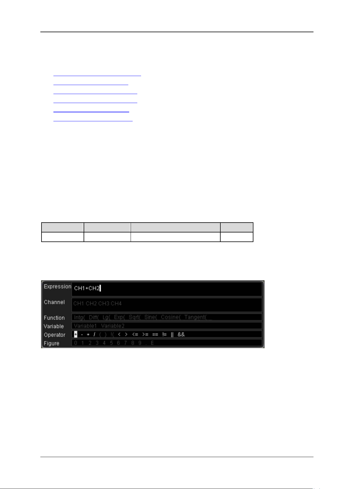
2 Command System RIGOL
2-69
:CALCulate:ADVanced
:CALCulate:ADVanced:EXPRession
:CALCulate:ADVanced:INVert
:CALCulate:ADVanced:VARiable1
:CALCulate:ADVanced:VARiable2
:CALCulate:ADVanced:VSCale
:CALCulate:ADVanced:VOFFset
:CALCulate:ADVanced:EXPRession
Syntax
:CALCulate:ADVanced:EXPRession <expression>
:CALCulate:ADVanced:EXPRession?
Description
Set or query the expression of advanced operation.
Parameter
Name Type Range Default
<expression> ASCII string Refer to Explanation CH1+CH2
Explanation
Input valid expressions using the characters as shown i n the figure below.
Note: The length of t he expression should be no greater than 64 bytes.
Return Format
The query returns the current expression in string.
DS2000E Programming Guide
Page 86
RIGOL 2 Command System
:CALCulate:ADVanced:INVert
Syntax
:CALCulate:ADVanced:INVert <bool>
:CALCulate:ADVanced:INVert?
Description
Enable or disable the inverted display of the advanced operation result; or query the current status of the
inverted display of the advanced operation result.
Parameter
Name Type Range Default
<bool> Bool {{1|ON}|{0|OFF}} 0|OFF
Return Format
The query returns 1 or 0.
2-70 DS2000E Programming Guide
Page 87
2 Command System RIGOL
2-71
:CALCulate:ADVanced:VARiable1 :CALCulate:ADVanced:VARiable2
Syntax
:CALCulate:ADVanced:VARiable1 <numeric_value>
:CALCulate:ADVanced:VARiable1?
:CALCulate:ADVanced:VARiable2 <numeric_value>
:CALCulate:ADVanced:VARiable2?
Description
Set or query the variable1 in the advanced operation expression.
Set or query the variable2 in the advanced operation expressi on.
Parameter
Name Type Range Default
<numeric_value> Real Refer to Explanation 0
Explanation
The format of <numeric_value> is AeB. The range of A (mantissa) is from -9.9999 to 9.9999 (the
minimum step is 0.0001; namely the number can contain at most 4 decimal places). B (exponent, its
base is 10) is an integer from -9 to 9. For example, 1.2037e5 de notes setting the viariable to
1.2037×10
that in AeB format.
This command sets the value of variable1 or variab le2 which might be used in
the
:CALCulate:ADVanced:EXPRession command.
Return Format
The query returns the value of variable1 or variable2 in the advanced operation expression in scientific
notation.
5
. <numeric_value> can also be expressed in decimal format; its range corresponds to
DS2000E Programming Guide
Page 88
RIGOL 2 Command System
:CALCulate:ADVanced:VSCale
Syntax
:CALCulate:ADVanced:VSCa le <numeric_value>
:CALCulate:ADVanced:VSCale?
Description
Set or query the vertical scale of the advanced operation result. The unit is related to the advanced
operation expression.
Parameter
Name Type Range Default
The default range is from 0.02V to 500V.
<numeric_value> Real
The actual range is related to the advanced
2V
operation expression.
Note: For the advanced operation expression, refer to the :CALCulate:ADVanced:EXPRession command. The
expression might include CH1 or CH2; at this point, the actual ra nge of <numeric_value> ia also related to the
channel vertical scale. For the channel vertical scale, refer to the
:CHANnel<n>:SCALe command.
Return Format
The query returns the vertical scale of the advanced operation result in scientific notation.
:CALCulate:ADVanced:VOFFset
Syntax
:CALCulate:ADVanced:VOFFset <offs>
:CALCulate:ADVanced:VOFFset?
Description
Set or query the vertical offset of the advanced operation result. The unit is related to the advanced
operation expression.
Parameter
Name Type Range Default
<offs> Real (-40 x VScale) to (40 x VScale) 0
Note: For the VScale (the vertical scale of MATH), refer to the :CALCulate:ADVanced:VSCale command.
Return Format
The query returns the vertical offset of the advanced operation result in scientific notation.
2-72 DS2000E Programming Guide
Page 89

2 Command System RIGOL
2-73
:CALibrate Commands
:CALibrate:DATE?
:CALibrate:STARt
:CALibrate:TIME?
:CALibrate:QUIT
:CALibrate:DATE?
Syntax
:CALibrate:DATE?
Description
Query the date of the last calibration.
Return Format
The query returns the date in <year>,<month>,<day> format. Wherein, <day> and <month> are
double-digit figures, and <year> is a four-digit figure. For example, 2013,10,27.
:CALibrate:STARt
Syntax
:CALibrate:STARt
Description
The oscilloscope starts to execute self-calibration.
Explanation
The self-calibration can make the oscilloscope quickly reach its optimum working state to obtain the
most accurate measurement values.
The functions of most of th e keys are disabled during the self-calibration.
DS2000E Programming Guide
Page 90

RIGOL 2 Command System
:CALibrate:TIME?
Syntax
:CALibrate:TIME?
Description
Query the time of the last calibration.
Return Format
The query returns the time in <hours>,<minutes>,<seconds> format. Wherein, <hours>, <minutes>,
and <seconds> are all double-digit figures. For example, 15,19,25.
:CALibrate:QUIT
Syntax
:CALibrate:QUIT
Description
Exit the self-calibration at any time.
2-74 DS2000E Programming Guide
Page 91
2 Command System RIGOL
2-75
:CHANnel<n> Commands
:CHANnel<n>:BWLimit
:CHANnel<n>:COUPling
:CHANnel<n>:DISPlay
:CHANnel<n>:INVert
:CHANnel<n>:IMPedance
:CHANnel<n>:OFFSet
:CHANnel<n>:SCALe
:CHANnel<n>:PROBe
:CHANnel<n>:UNITs
:CHANnel<n>:VERNier
:CHANnel<n>:TCAL
:CHANnel<n>:BWLimit
Syntax
:CHANnel<n>:BWLimit <type>
:CHANnel<n>:BWLimit?
Description
Set or query bandwidth lim it of the specified analog channel.
Parameter
Name Type Range Default
<n> Discrete {1|2} -<type> Discrete {20M|100M|OFF} OFF
Note: For 100MHz oscilloscopes, the bandwidth limit can only be 20MHz.
Return Format
The query returns 20M, 100M, or OFF.
DS2000E Programming Guide
Page 92
RIGOL 2 Command System
:CHANnel<n>:COUPling
Syntax
:CHANnel<n>:COUPling <coupling>
:CHANnel<n>:COUPling?
Description
Set or query the coupling mode of the specified analog channel.
Parameter
Name Type Range Default
<n> Discrete {1|2} -<coupling> Discrete {AC|DC|GND} DC
Explanation
AC: the DC components of the signal under test are blocked.
DC: the DC and AC com ponents of the signal under test can both pass the channel.
GND: the DC and A C components of the signal under tes t are both blocked.
Return Format
The query returns AC, DC, or GND.
:CHANnel<n>:DISPlay
Syntax
:CHANnel<n>:DISPlay <bool>
:CHANnel<n>:DISPlay?
Description
Enable or disable the specified analog channel; or q uery the current status of the specified analog
channel.
Parameter
Name Type Range Default
<n> Discrete {1|2} -<bool> Bool {{1|ON}|{0|OFF}} 1|ON
Return Format
The query returns 1 or 0.
2-76 DS2000E Programming Guide
Page 93
2 Command System RIGOL
2-77
:CHANnel<n>:INVert
Syntax
:CHANnel<n>:INVert <bool>
:CHANnel<n>:INVert?
Description
Enable or disable the inverted display of the speci fied analog channel; or query the current status of the
inverted display of the specified analog channel.
Parameter
Name Type Range Default
<n> Discrete {1|2} -<bool> Bool {{1|ON}|{0|OFF}} 0|OFF
Return Format
The query returns 1 or 0.
:CHANnel<n>:IMPedance
Syntax
:CHANnel<n>:IMPedance <impedance>
:CHANnel<n>:IMPedance?
Description
Set or query the input impedance of the specified analo g channel. The default unit is Ω.
Parameter
Name Type Range Default
<n> Discrete {1|2} -<type> Discrete {OMEG|FIFTy} OMEG
Explanation
OMEG: 1MΩ; FIFTy: 50Ω
Return Format
The query returns OMEG or FIFT.
DS2000E Programming Guide
Page 94

RIGOL 2 Command System
:CHANnel<n>:OFFSet
Syntax
:CHANnel<n>:OFFSet <offset>
:CHANnel<n>:OFFSet?
Description
Set or query the vertical offset of the specifie d analog channel. The default unit is V.
Parameter
Name Type Range Default
<n> Discrete {1|2} --
When the input impedance is 50Ω and the
probe ratio is 1X:
500μV/div to 50mV/div: -2V to 2V
51mV/div to 200mV/div: -10V to 10V
205mV/div to 1V/div: -12V to 12V
<offset> Real
When the input imped ance is 1MΩ and the
probe ratio is 1X:
500μV/div to 50mV/div: -2V to 2V
51mV/div to 200mV/div: -10V to 10V
205mV/div to 2V/div: -50V to 50V
2.05V/div to 10V/div: -100V to 100V
Note: The range of the vertical offset is related to the vertical scale, probe ratio, and input impedance currently set.
For the vertical scale, refer to the
the
:CHANnel<n>:PROBe command. For the input impedance, refer to the :CHANnel<n>:IMPedance command.
:CHANnel<n>:SCALe command. For the probe ratio, refer t o
Return Format
The query returns the vertical offset of the specified analog channel i n scientific notation.
CHANnel1: 2V
CHANnel2: -2V
2-78 DS2000E Programming Guide
Page 95
2 Command System RIGOL
2-79
:CHANnel<n>:SCALe
Syntax
:CHANnel<n>:SCALe <scale>
:CHANnel<n>:SCALe?
Description
Set or query the vertical scale of the specified analog channel. The default unit is V/div.
Parameter
Name Type Range Default
<n> Discrete {1|2} --
When the input impeda nce is 50Ω
and the probe ratio is 1X:
<scale> Real
Note: The range of the vertical scale is related to the probe ratio and input impedance currently set. For the setting
of the probe ratio, refer to the
the
:CHANnel<n>:IMPedance command.
Return Format
The query returns the vertical scale of the specified analog channel in scientific notation.
500μV/div to 1V/div
When the input impedance is 1MΩ
and the probe ratio is 1X:
500μV/div to 10V/div
:CHANnel<n>:PROBe command. For the input impedance, refer to
1V/div
DS2000E Programming Guide
Page 96
RIGOL 2 Command System
:CHANnel<n>:PROBe
Syntax
:CHANnel<n>:PROBe <atten>
:CHANnel<n>:PROBe?
Description
Set or query the probe attenuation ratio of the specified analog channel.
Parameter
Name Type Range Default
<n> Discrete {1|2} -<atten> Discrete
Explanation
After setting the probe ratio, multiply the sampled signal by the specified multiple, and then d isplay
the result (the actual amplitude of the signal will not be affected).
Setting the probe ratio affects the range of the vertical scale.
Return Format
The query returns the attenuation ratio currently set.
{0.01|0.02|0.05|0.1|0.2|0.5|1|2|5|10|20|
50|100|200|500|1000}
1
:CHANnel<n>:UNITs
Syntax
:CHANnel<n >: UNI Ts <un it s >
:CHANnel<n>:UNITs?
Description
Set or query the amplitude display unit of the specified analog channel.
Parameter
Name Type Range Default
<n> Discrete {1|2} -<units> Discrete {VOLTage|WATT|AMPere|UNKNown} VOLTage
Return Format
The query returns VOLT, WATT, AMP, or UNKN.
2-80 DS2000E Programming Guide
Page 97
2 Command System RIGOL
2-81
:CHANnel<n>:VERNier
Syntax
:CHANnel<n>:VERNier <bool>
:CHANnel<n>:VERNier?
Description
Enable or disable the fine adjustment function of the vertical scale of the specified analog channel; or
query the current status of the fine adjustment function of the vertical scale o f the specified analog
channel.
Parameter
Name Type Range Default
<n> Discrete {1|2} -<bool> Bool {{1|ON}|{0|OFF}} 0|OFF
Explanation
By default, the fine adjus tment function is disabled. At this point, you can only set t he vertical scale in
1-2-5 step; namely 500uV/div, 1 mV/div, 2mV/div, 5mV/div, 10mV/div…10V/div. When the fine adjustment
function is enabled, you can further adjust the vertical scale within a relatively smaller range to improve
vertical resolution. If the amplitud e of the input waveform is a little bit greater than the full scale under
the current scale, and the amplitude would be a little bit lower if the next sca le is used, fine adjustment
can be used to improve the amplitude of waveform display to view signal details.
Return Format
The query returns 1 or 0.
DS2000E Programming Guide
Page 98
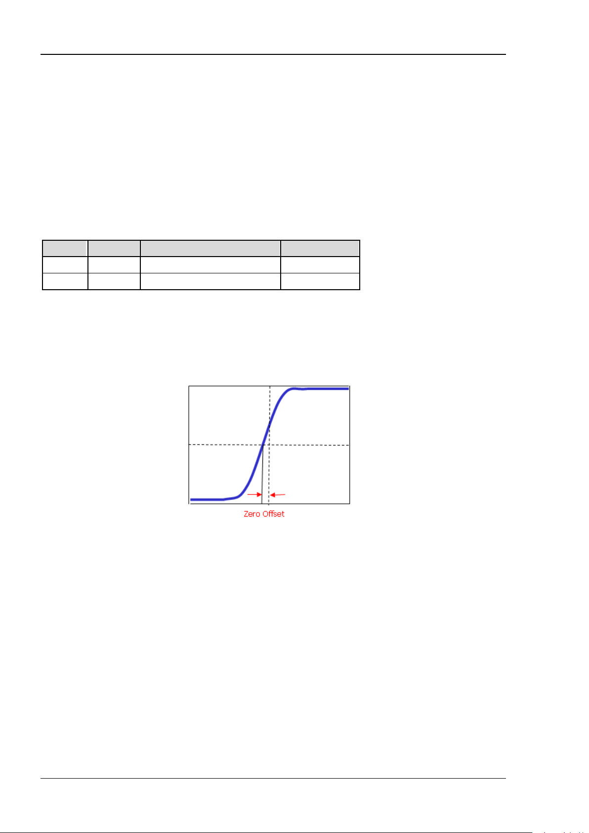
RIGOL 2 Command System
:CHANnel<n>:TCAL
Syntax
:CHANnel<n>:TCAL <time>
:CHANnel<n>:TCAL?
Description
Set or query the delay calib r ation time of the specified analog channel. The default unit is s.
Parameter
Name Type Range Default
<n> Discrete {1|2} -<time> Real -200ns to 200ns 0s
Note: When the horizontal timebase is greater than or equal to 10us, the delay calibration time cannot be adjusted.
Explanation
When you use an oscilloscope for actual measurement, the transmission delay of the probe cable may
bring relatively greater error (zero offset). Z ero offset is defined as the offset of the crossing point of the
waveform and trigger level line relative to the trigger position, as shown in the figure below.
Return Format
The query returns the delay calibration time of the specified analog channel in scientific notation.
2-82 DS2000E Programming Guide
Page 99
2 Command System RIGOL
2-83
:CURSor Commands
:CURSor:MODE
:CURSor:MANual
:CURSor:TRACk
:CURSor:MODE
Syntax
:CURSor:MODE <mode>
:CURSor:MODE?
Description
Set or query the cursor measurement mode.
Parameter
Name Type Range Default
<mode> Discrete {OFF|MANual|TRACk|AUTO|XY} OFF
Explanation
OFF: disable the cursor measurement.
MANual: enable the manual measurement with cursor.
TRACk: enable the track measurement with cursor.
AUTO: enable the auto measurement with cursor.
XY: enable the X-Y curs or measurement. This mode is only valid when the horizontal time base mode
is X-Y (please refer to the
Return Format
The query returns OFF, MAN, TRAC, AUTO, or XY.
:TIMebase:MODE command).
DS2000E Programming Guide
Page 100
RIGOL 2 Command System
:CURSor:MANual
:CURSor:MANual:TYPE
:CURSor:MANual:SOURce
:CURSor:MANual:TUNit
:CURSor:MANual:VUNit
:CURSor:MANual:CAX
:CURSor:MANual:CBX
:CURSor:MANual:CAY
:CURSor:MANual:CBY
:CURSor:MANual:AXValue?
:CURSor:MANual:BXValue?
:CURSor:MANual:AYValue?
:CURSor:MANual:BYValue?
:CURSor:MANual:XDELta?
:CURSor:MANual:IXDelta?
:CURSor:MANual:YDELta?
:CURSor:MANual:TYPE
Syntax
:CURSor:MANua l:TYPE <type>
:CURSor:MANual:TYPE?
Description
Set or query the cursor type of manual measurement with cursor.
Parameter
Name Type Range Default
<type> Discrete {TIME|AMPLitude} TIME
Explanation
TIME: X cursors which are usually used to measure time parameters.
AMPLitude: Y cursors which are usually used to measure voltage parameters.
Return Format
The query returns TIME or AMPL.
2-84 DS2000E Programming Guide
 Loading...