

Page 1

RIGOL
User’s Guide
DS2000A Series Digital Oscilloscope
Sept. 2013
RIGOL Technologies, Inc.
Page 2

Page 3

RIGOL
I
Guaranty and Declaration
Copyright
© 2013 RIGOL Technologies, Inc. A ll Rights Reserved.
Trademark Information
RIGOL is a registered trademark of RIGOL Technologies, Inc.
Publication Number
UGA16102-1112
Notices
RIGOL products are protected by patent law in and outside of P.R.C.
RIGOL reserves the right to modify or change parts of or all the specifications
and pricing policies at company’s sole decision.
Information in this publication replaces all previously corresponding material.
RIGOL shall not be liable f or losses caused by either inc idental or consequential
in connection with the furnishing, use or performance of this manual as well as
any information contained.
Any part of this document is forbidden to be copied or photocopied or
rearranged without prior written approval of RIGOL.
Product Certification
RIGOL guar antees this pr oduct confo rms to the national and i ndus trial s tandar ds in
China as well as the ISO9001:2008 standard and the ISO14001:2004 standard.
Other international standard conformance cert ification is in progress.
Contact Us
If you have any problem or requirement when using our products or this manual,
please contact RIGOL.
E-mail: service@rigol.com
Websites: www.rigol.com
DS2000A User’s Guide
Page 4

RIGOL
II
Safety Requirement
General Safety Summary
Please review the following safety precautions carefully before putting the
instrument into operation so as to avoid any personal injury or damage to the
instrument and any p roduct connec ted to it. To prevent potential hazards, p lease use
the instrument only specified by this manual.
Use Proper Power Cord.
Only the power cord designed for the instrument and authorized for use within the
local country could be used.
Ground The Instrument.
The instrument is grounded through the Protective Earth lead of the power cord. To
avoid electric shock, it is essent ial to connect the earth termina l of power c ord t o the
Protective Earth terminal before any inputs or outputs.
Connect the Probe Correctly.
If a probe is used, do not connect the ground lead to high voltage since it has the
isobaric electric potential as ground.
Observe All Terminal Ratings.
To avoid fire or s hock ha z ard , obs erve all r atings and m arkers on the i nst rument and
check your manual for more information about ratings before connecting.
Use Proper Overvoltage Protection.
Make sure that no overvoltage (such as that caused by a thunderstorm) can reach
the product, or else the operator might expose to danger of electrical shock.
Do Not Operate Without Covers.
Do not operate the instrument with covers or panels removed.
Do Not Insert Anything into the Holes of Fan.
Do not insert anything into the holes of the fan to avoid damaging the instrument.
DS2000A User’s Guide
Page 5

RIGOL
III
Use Proper Fuse.
Please use the specif ied fuses.
Avoid Circuit or Wire Exposure.
Do not touch exposed junctions and components when the unit is powered.
Do Not Operate With Suspected Failures.
If you suspect damage occurs to the instrument, have it inspected by qualified
service personnel before further operations. Any maintenance, adjustment or
replacement especial ly to circuits or accessories must be performed by RIGOL
authorized personnel.
Keep Well Ventilation.
Inadequate ventilation may cause increasing of temperature or damages to the
device. So please keep well ventilated and inspect the intake and fan regularly.
Do Not Operate in Wet Conditions.
In order to av oid s hort circuiting to the inte rior of the device or electric shock, please
do not operate in a humid environment.
Do Not Operate in an Explosive Atmosphere.
In order to avoid damages to the device or personal injuries, it is important to
operate the device away from an explosive atmosphere.
Keep Product Surfaces Clean an d Dry .
To avoid the influence of dust and/or moisture in air, please keep the surface of
device clean and dry.
Electrostatic Prevention.
Operate in an electrostatic discharge protective area environment to avoid damages
induced by static discharges. Always ground both the internal and external
conductors of the cable t o rel ea se static before connecting.
Proper Use of Battery.
If a battery is supplied, it must not be exposed to high temperature or in contact with
fire. Keep it out of the reach of children. Improper change of battery (note: lithium
battery) may cause explosion. Use RIGOL specified battery only.
DS2000A User’s Guide
Page 6
RIGOL
IV
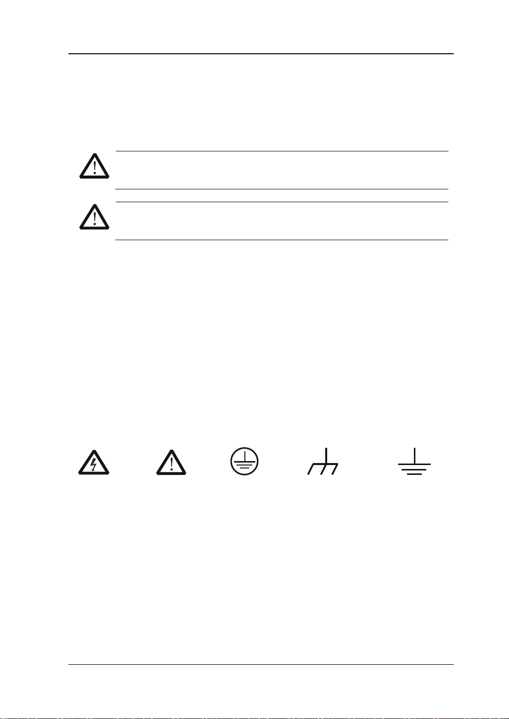
DANGER
CAUTION
indicates potential damage to the instrument or other property might
Hazardous
Safety
Protective
Chassis
Test
Handling Safety.
Please handle with care during transportation to avoid damages to buttons, knob
interfaces and other parts on the panels.
Safety Terms and Symbols
Terms Used in this Manual. These terms may appear in this manual:
WARNING
Warning statements indicate the conditions or practices that could result
in injury or loss of life.
CAUTION
Caution statements indicate the c onditions or p rac tices t hat could res ult in
damage to this product or other property.
Terms Used on the Product. These terms may appear on the Product:
indicates an injury or hazard may immediately happen.
WARNING
Symbols Used on the Product. These symbols may appear on the product:
indicates an injury or hazard may be accessible potentially.
occur.
Voltage
Warning
Earth
Terminal
Ground
Ground
DS2000A User’s Guide
Page 7

RIGOL
V
Allgemeine Sicherheits Informationen
Überprüfen Sie diefolgenden Sicherheitshinweise
sorgfältigumPersonenschädenoderSchäden am Gerätundan damit verbundenen
weiteren Gerätenzu vermeiden.Zur Vermeidung vonGefahren, nutzen Sie bitte das
Gerät nur so, wiein diesem Handbuchangegeben.
Um Feuer oder Verletzungen zu vermeiden, verwenden Sie ein
ordnungsgemäßes Netzkabel.
Verwenden Sie für dieses Gerät nur das für ihr Land zugelassene und genehmigte
Netzkabel.
Erden des Gerätes.
Das Gerät ist durch den Schutzleiter im Netzkabel geerdet. Um Gefahren durch
elektrischen Schlag zu verme iden, ist es unerläss lich, die Erdung durchzufüh ren. Erst
dann dürfen weitere Ein- oder Ausgänge verbunden werden.
Anschluss einesTastkopfes.
Die Erdungsklemmen der Sonden sindauf dem gleichen Spannungspegel des
Instruments geerdet. SchließenSie die Erdungsklemmen an keine hohe Spannung
an.
Beachten Sie alle Anschlüsse.
Zur Vermeidung von Feuer oder Stromschlag, beachten Sie alle Bemerkungen und
Markierungen auf dem Instrument. Befolgen Sie die Bed ienungsanleitung für weitere
Informationen, bevor Sie weitere Anschlüsse an das Instrument legen.
Verwenden Sie einen geeigneten Überspannungsschutz
Stellen Sie sicher, daß keinerlei Überspannung (wie z.B. durch Gewitter verursacht)
das Gerät erreichen kann. Andernfallsbestehtfür den Anwender die
GefahreinesStromschlages.
Nicht ohne Abdeckung einschalten.
Betreiben Sie das Gerät nicht mit entfernten Gehäuse-Abdeckungen.
Betreiben Sie das Gerät nicht geöffnet
Der Betrieb mit offenen oder entfernten Gehäuseteilen ist nicht zulässig. Nichts in
entsprechende Öffnungen stecken (Lüfter z.B.)
Passende Sicherung verwenden
Setzen Sie nur die spezifikationsgemäßen Sicherungen ein.
Vermeiden Sie ungeschützte Verbindungen
Berühren Sie keine unisolierten Verbindungen oder Baugruppen, während das Gerät
DS2000A User’s Guide
Page 8

RIGOL
VI
in Betrieb ist.
Betreiben Sie das Gerät nic h t i m Fehlerfall
Wenn Sie am Gerät einen Defekt vermuten, sorgen Sie dafür, bevor Sie das Gerät
wieder betreiben, dass e ine Untersuc hung durch qua lifiziertes Kund endienstpers onal
durchgeführt wird.Jedwede Wartung, Einstellarbeiten oder Austausch von Teilen am
Gerät, sowie am Zubehör dürfen nur von RIGOL autorisiertem Personal
durchgeführt werden.
Belüftung sicherstellen
Unzureichende Belüftung kann zu Temperaturanstiegen und somit zu thermischen
Schäden am Gerät führen. Stellen Sie deswegen die Belüftung sicher und
kontrollieren regelmäßig Lüfter und Belüftungsöffnungen.
Nicht in feuc h te r Um g ebung betrei be n
Zur Verm eidung von K urzschluß im G eräteinneren und Stromschlag b etreiben Sie das
Gerät bitte niemals in feuchter Umgebung.
Nicht in explosiver Atmosphäre betreiben
Zur Vermeidung von Personen- und Sachschäden ist es unumgänglich, das Gerät
ausschließlich fernab jedweder explosiven Atmosphäre zu betreiben.
Geräteoberflächen sauber und trocken halten
Um den Einfluß von Staub und Feuchtigkeit aus der Luft auszuschließen, halten Sie
bitte die Geräteoberflächen sauber und trocken.
Schutz gegen elektrostatische Entladung (ESD)
Sorgen Sie für eine elektrostatisch geschützte Umgebung, um somit Schäden und
Funktionsstörungen durch ESD zu vermeiden. Erden Sie vor dem Anschluß immer
Innen- und Außenleiter d er V erbindungs leitung, um s tatische Aufladung zu e ntladen.
Die richtige Verwendung desAkku.
Wenneine Batterieverwendet wird, vermeiden Sie hohe Temperaturen bzw. Feuer
ausgesetzt werden.Bewahren Sie es außerhalbder Reichweitevon Kindern
auf.UnsachgemäßeÄnderung derBatterie(Anmerkung:Lithium-Batterie)kann zu einer
Explosion führen. VerwendenSie nur von RIGOLangegebenenAkkus.
Sicherer Transport
Transportieren Sie das Gerät sorgfältig (Verpackung!), um Schäden an
Bedienelementen, Anschlüssen und anderen Teilen zu vermeiden.
DS2000A User’s Guide
Page 9
RIGOL
VII
WARNING
Schäden oder den Tod von Personen zur Folge haben können.
CAUTION
Schäden am Gerät hervorrufen können.
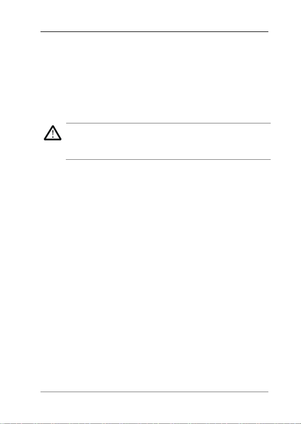
DANGER
weist auf eine Verletzung oder Gefährdung hin, die sofort
geschehen kann.
WARNING
weist auf eine V erletzung ode r Gefährdung hin, d ie möglicherweis e
nicht sofort geschehen.
CAUTION
bedeutet, dass eine mögliche Beschädigung des Ins truments oder
anderer Gegenstände auftreten kann.
Sicherheits Begriffe und Symbole
Begriffe in diesem Guide. Diese Begriffe können in diesem Handbuch
auftauchen:
Die Kennzeichnung WARNING beschreibt Gefahrenquellen die leibliche
Die Kennzeichnung Caution (Vorsicht) beschreibt Gefahrenquellen die
Begriffe auf dem Produkt. Diese Bedingungen können auf dem Produkt
erscheinen:
Symbole auf dem Produkt. Diese Symbole können auf dem Produkt
erscheinen:
GefährlicheS
pannung
SicherheitsHinweis
Schutz-erde Gehäusemasse Erde
DS2000A User’s Guide
Page 10
RIGOL
VIII
WARNING
Measurement Category
Measurement Category
DS2000A series digital oscilloscopes can make measurements in Measurement
Category I.
This oscilloscope can only be used for measurements within its specified
measurement categories.
Measurement Category Definitions
Measurement category I is for measurements performed on circuits not directly
connected to MAINS. Examples are measurements on circuits not derived from
MAINS, and specially protected (internal) MAINS derived circuits. In the latter case,
transient stresses are variable; for that reason, the transient withstand capability of
the equipment is made known to the user.
Measurement category II is for measurements performed on circuits directly
connected to the low volta ge ins tallation. Exam ples are meas urements on household
appliances, portable tools and similar equipment.
Measurement category III is fo r meas urements p erformed in the b uilding ins tallation.
Examples are measurements on distribution boards, circuit-breakers, wiring,
including cables, bus-bars, junction boxes, switches, socket-outlets in the fixed
installation, and equipment for industrial use and some other equipment, for
example. Stationary motors with permanent connection to the fixed installation.
Measurement category IV is for measurements performed at the source of the
low-voltage installation. Examples are electricity meters and measurements on
primary overcurrent protection devices and ripple control units.
DS2000A User’s Guide
Page 11
RIGOL
IX
WARNING
Ventilation Requirement
This oscilloscope uses fan to force cooling. Please make sure that the air intake and
exhaust areas are free from obstructions and have free air. When using the
oscilloscope in a bench-top or rack setting, provide at least 10 cm clearance beside,
above and behind the instrument for adequate ventilation.
Inadequate ventilation may cause temperature increase which would
damage the instrument. So please keep the instrument well ventilated
during operation and inspect the intake and fan regularly.
DS2000A User’s Guide
Page 12
RIGOL
X
o avoid short circuit i nside the i nstrument or electric shock, p lease d o not
WARNING
Working Environment
Temperature
Operating: 0℃ to +50℃
Non-operating: -40℃ to +70℃
Humidity
0℃ to +30℃: ≤95% relative humidity
+30℃ to +40℃: ≤75% relative humidity
+40℃ to +50℃: ≤45% relative humidity
WARNING
T
operate in humid environment.
Altitude
Operating: less than 3 km
Non-operating: less than 15 km
Installation (overvoltage) Category
This product is powered by mains conforming to installation (overvoltage) category
II.
Make sure that no overvoltage (such as that caused by thunderbolt) can
reach the product, or else the operator might expose to danger of electric
shock.
Installation (overvoltage) Category Definitions
Installation (overvoltage) category I refers to signal level which is applicable to
equipment measurement terminals connected to the source circuit. In these
terminals, precautions are done to limit the transient voltage to the corresponding
low level.
Installation (overvoltage) category II refers to the local power distribution level
which is applicable to equipment connected to the AC line (AC power).
DS2000A User’s Guide
Page 13

RIGOL
XI
Pollution Degree
Degree 2
Pollution Degree Definitions
Pollution degree 1: No pollution or only dry, non-conductive pollution occurs. The
pollution has no influence. For example: a clean room or air-conditioned office
environment.
Pollution degree 2: Normally only dry, non-conductive pollution occurs. Occasionally
a temporary conductivity caused by co n de n sati o n may o ccu r. For example: general
indoor environment.
Pollution degree 3: Conductive pollution occurs, or dry, non-conductive pollution
occurs which becomes conductive due to condensation which is expected. For
example: Sheltered outdoor environment.
Pollution degree 4: Pollution that generates persistent conductivity through
conductive dust, rain, or snow. For example: outdoor locations.
Safety Class
Class 1 – Grou n de d Pro duct
DS2000A User’s Guide
Page 14
RIGOL
XII
General Care and Cleaning
General Care:
Do not store or leave the instrume nt at places where the instrument will b e exposed
to direct sunlight for long periods of time.
Cleaning:
Clean the instrument regularly according to its operating conditions. To clean the
exterior surface:
1. Disconnect the instrument from all power sources.
2. Clean the l oose dust on the outs ide of the instrument with a lint- free cl oth (with
mild detergent or water). When cleaning the LCD, ta ke c a re to avoid scarifying
it.
CAUTION
To avoid damages to the instrument, do not expose them to corrosive
liquids.
WARNING
To avoid injury resulting from short circuit, make sure the instrument is
completely dry before reco n n ect in g it to a power source.
DS2000A User’s Guide
Page 15
RIGOL
XIII
Environmental Consideratio ns
The following symbol indicates that this product complies with the applicable
European Union requirements according to Directives 2002/ 96/EC on waste electrical
and electronic equipment (WEEE).
Product End-of-Life Handling
The equipment may contain substances tha t could be harmful to the envi ronm ent or
human health. In order to avoid release of suc h substances i nto the environment and
harm to human health, we encourage you to recycle this product in an appropriate
system that will ensure that most of the materials are reused or recycled
appropriately. Please contact your local authorities for disposal or recycling
information.
DS2000A User’s Guide
Page 16

RIGOL
XIV
DS2000A Series Overview
DS2000A is a high-performance digital oscillosco pe developed on the basis of the
Ultra Vision technique. DS2000A, featuring rather deep memory depth, ultra-wide
dynamic range, superb waveform capture rate and all-round trigger functions as well
as hardware waveform record function and good display e ffect, is an invaluable
debug instrument in various fields (such as communication, cosmonautics, defense,
embedded system, computer, research and educa ti o n ) a n d is th e on e w i th the most
complete functions and most outstanding specifications among the digital
oscilloscopes with lower than 300 MHz bandwidth.
Main feature s:
300MHz, 200 MHz, 100 MHz and 70 MHz bandwidth.
Ultra Vision technique.
2 GSa/s maximum r eal-time sample rate.
50,000 wfms/s (dots display) waveform captu re rate.
Real-time hardware waveform recording, waveform playback, record open
(constant on) and waveform analysis functions. Up to 65,000 frames of
waveform can be recorded.
56 Mpts maximum memory depth (option) and 14 Mpts standard memory
depth.
256 degree gray scale display.
Low noise floor, 500 μV/div to 10 V/div ultra-wide vertical dynamic range.
8.0 inches, WVGA (800*480) 160,000 color TFT LCD, with ultra-wide screen,
vivid picture, low power consumption and long service life.
Adjustable brightness of analog channel waveform.
Auto setting of waveform display (AUTO).
16 kinds of trigger functions including multiple protocol triggers.
Standard parallel decodi ng and multiple serial decoding options.
Auto measurements of 24 waveform parameters and measurement functions
with statistic.
Precise delayed sweep function.
Built-in FFT function.
Pass/Fail test function.
Multiple waveform math operation functions.
Built-in dual-channel and 25 MHz signal generator function (only applicable to
DS2000A-S).
Standard configuration inte rfaces: USB Device, USB Host, LAN and GPIB
DS2000A User’s Guide
Page 17

RIGOL
XV
(optional).
Support USB storage device and PictBrige printer.
Conform to LXI-C instrument standards. Enable quick, economic and efficient
creation and reconfiguration of test system.
Support remote command control.
Embedded help enables easier information access.
Support multiple languages and Chinese/English input.
Novel and delicate industrial design and easier operation.
DS2000A User’s Guide
Page 18

RIGOL
XVI
1 Quick Star t
Provide information about preparations
introduction of the instrument.
2 To Set the Vertical System
Introduce the functions of the vertical
system of the osci lloscope.
3 To Set the Horizontal System
Introduce the functions of the horizontal
system of the osci lloscope.
4 To Set the Sample System
Introduce the functions of the sample
5 To Trigger the Oscilloscope
Introduce the trigger mode, trigger coupling,
6 To Make Measurements
Introduce how to make math operation,
measurement.
7 Protocol Decoding
Introduce how to decode the input signal
using those common protocols.
8 Reference Waveform
Introduce how to compare the input
waveform with the reference waveform.
9 Pass/Fail Test
Introduce how to monitor the input signal
using the Pass/Fail test.
10 Waveform Record
Introduce how to analyze the input signal
using waveform record.
11 Display Control
Introduce how to control the display of the
oscilloscope.
12 Signal Source
Introduce how to use the built-in signal
generator.
13 Store and Recall
Introduce how to store and recall the
oscilloscope.
14 System Function Setting
Introduce how to set the remote interface
and system-related functions.
15 Remote Control
Introduce how to control the oscilloscope
16 Troubleshooting
Introduce how to deal with common failures
of the oscilloscope.
17 Specifications
Provide the specifications and general
specifications of the oscilloscope.
18 Appendix
Provide common information such as options
Document Overview
before using the instrument and a brief
system of the osci lloscope.
trigger holdoff, external trigger and various
trigger types of the oscillo scope.
cursor measurement and auto
measurement result and the setting of the
remotely.
and accessories.
DS2000A User’s Guide
Page 19
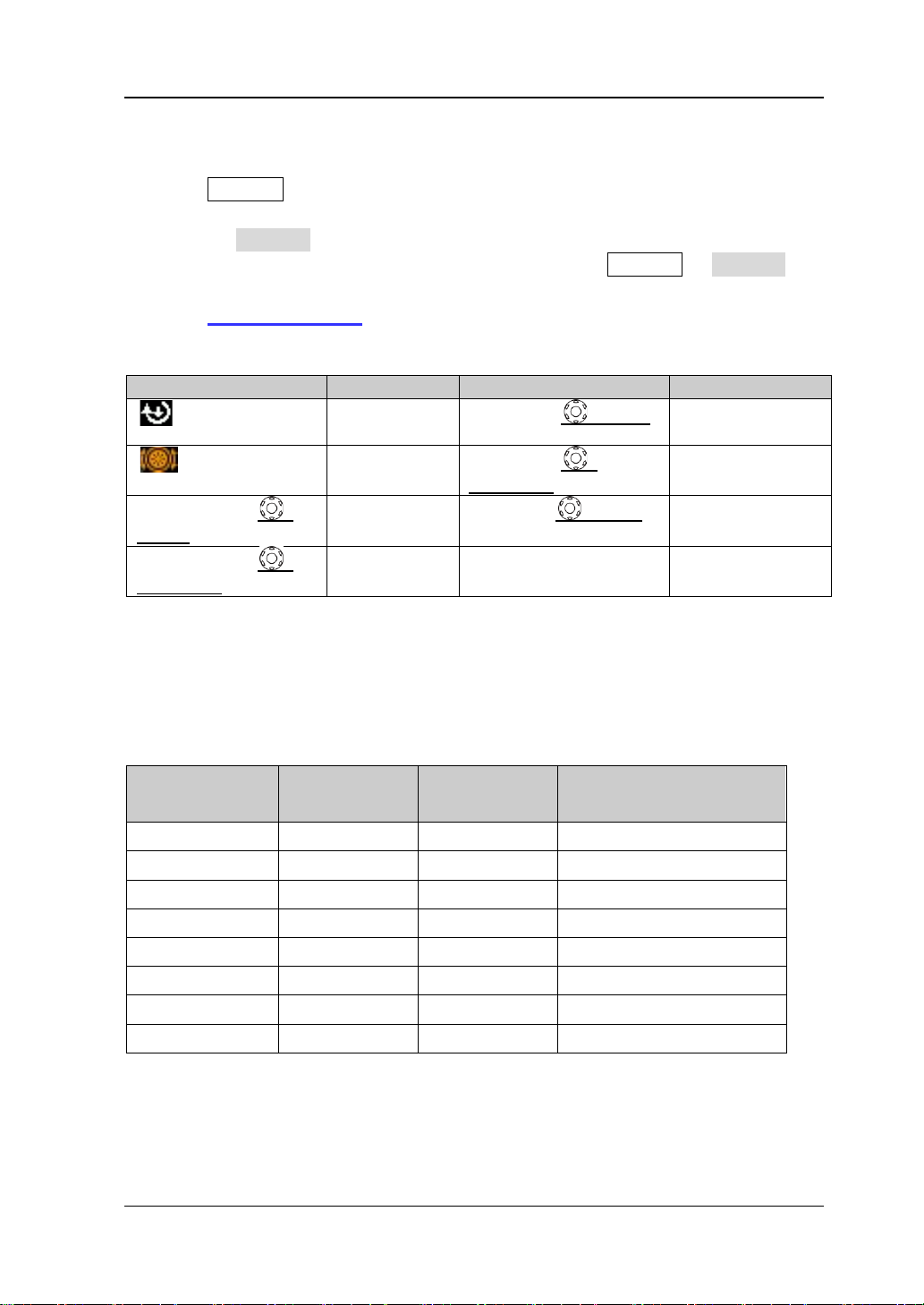
RIGOL
XVII
Logo
Knob
Logo
Knob
Multi-function
Vertical Scale
Navigation
Vertical Position
Horizontal
Trigger Level
POSITION
Horizontal
--
--
Format Conventions in this Manual:
Front panel key: denoted by the format of “Text Box + Button Name (Bold)”, for
example, Storage.
Menu softkey: denoted by the format of “Charac te r Shading + Menu Word (Bold)”,
for example, Storage.
Operation steps: denoted by the arrow “”, for example, Storage Storage.
Cross reference: denoted by the format of “underscore + word (Blue and Bold), for
example,
Store and Recall.
Knob:
HORIZONTAL
SCALE
Knob
Knob
Scale Knob
VERTICAL SCALE
VERTICAL
POSITION
TRIGGER LEVEL
Knob
Knob
Knob
HORIZONTAL
Position Knob
Content Con v entions in this Man ual:
This manual takes DS 2302A -S for example and the d es criptions here ha ve cont ained
all the functions and performances of other models. DS2000A series includes the
following models:
Model
Analog
Bandwidth
Channels
Channels of the Signal
Generator
DS2072A 70 MHz 2 -DS2072A-S 70 MHz 2 2
DS2102A 100 MHz
2 -DS2102A-S 100 MHz 2 2
DS2202A 200 MHz 2 -DS2202A-S 200 MHz 2 2
DS2302A 300 MHz 2 -DS2302A-S 300 MHz 2 2
DS2000A User’s Guide
Page 20

RIGOL
XVIII
Contents
Guaranty and Declaration ......................................................................... I
Safety Requirement ................................................................................. II
General Safety Summary ............................................................................. II
Safety Terms and Symbo l s .......................................................................... IV
Allgemeine Sicherheits Informationen ........................................................... V
Sicherheits Begriffe und Symbole ............................................................... VII
Measurement Category ............................................................................. VIII
Ventilation Requirement .............................................................................. IX
Working Environment ...................................................................................X
General Care and Cleaning ......................................................................... XII
Environmental Considerations ................................................................... XIII
DS2000A Series Overview .................................................................... XIV
Document Overview ............................................................................. XVI
1 Quick Start ........................................................................................ 1-1
General Inspection .................................................................................... 1-2
Appearance and Dimensions ...................................................................... 1-3
To Prepare the Oscilloscope for Use ............................................................ 1-4
To Adjust the Supporting Legs ............................................................. 1-4
To Connect to Power Supply ................................................................ 1-4
Power-on Inspection ........................................................................... 1-5
To Connect the Probe ......................................................................... 1-5
Function Inspection ............................................................................ 1-6
Probe Compensation ........................................................................... 1-7
Front
Panel Overview ................................................................................. 1-8
Rear Panel Overview ................................................................................ 1-10
Front Panel Function Overview ................................................................. 1-12
VERTICAL ......................................................................................... 1-12
HORIZONTAL ................................................................................... 1-13
TRIGGER .......................................................................................... 1-14
CLEAR .............................................................................................. 1-14
RUN/STOP ........................................................................................ 1-14
SINGLE ............................................................................................ 1-15
DS2000A User’s Guide
Page 21

RIGOL
XIX
AUTO ............................................................................................... 1-15
Knob ................................................................................................ 1-16
Navigation Knob ............................................................................... 1-16
Menu ............................................................................................... 1-17
Source ............................................................................................. 1-18
Record ............................................................................................. 1-18
Print ................................................................................................ 1-19
User Interface ......................................................................................... 1-20
To Use the Security Lock .......................................................................... 1-24
To Use the Built-in Help System ............................................................... 1-25
2 To Set the Vertical System ................................................................. 2-1
To Enable the Channel ............................................................................... 2-2
Channel Coupling ...................................................................................... 2-3
Bandwidth Limit ........................................................................................ 2-3
Probe Ratio ............................................................................................... 2-4
Input Impedance....................................................................................... 2-4
Waveform Invert ....................................................................................... 2-5
Vertical Sca l e ............................................................................................ 2-5
Vertical Expansion ..................................................................................... 2-6
Amplitude Unit .......................................................................................... 2-6
Channel Label ........................................................................................... 2-7
Delay Calibration ....................................................................................... 2-8
3 To Set the Horizontal System ............................................................. 3-1
Delayed Sweep ......................................................................................... 3-2
Time Base Mode........................................................................................ 3-4
Y-T Mode ............................................................................................ 3-4
X-Y Mode ........................................................................................... 3-4
Roll Mode ........................................................................................... 3-7
Horizontal Scale ........................................................................................ 3-8
Horizontal Reference ................................................................................. 3-9
4 To Set the Sample System .................................................................. 4-1
Acquisition Mode ....................................................................................... 4-2
Normal ............................................................................................... 4-2
Average ............................................................................................. 4-2
Peak Detect ........................................................................................ 4-4
High Resolution .................................................................................. 4-4
DS2000A User’s Guide
Page 22

RIGOL
XX
Sample Mode ............................................................................................ 4-5
Sample Rate ............................................................................................. 4-6
Memory Depth .......................................................................................... 4-8
Antialiasing ............................................................................................... 4-9
5 To Trigger the Oscilloscope ............................................................... 5-1
Trigger Source ........................................................................................... 5-2
Trigger Mode ............................................................................................. 5-3
Trigger Coupling ........................................................................................ 5-5
Trigger Holdoff .......................................................................................... 5-6
Noise Rejection ......................................................................................... 5-7
Trigger Type .............................................................................................. 5-8
Edge Trigger ....................................................................................... 5-9
Pulse Tr igger .................................................................................... 5-10
Runt Tr igger ..................................................................................... 5-12
Windows Trigger (Option) ................................................................. 5-14
Nth Edge Trigger (Option) ................................................................. 5-16
Slope Trigger .................................................................................... 5-18
Video Trigger (HDTV Option) ............................................................. 5-21
Pattern Trigger ................................................................................. 5-23
Delay Trigger (Option) ...................................................................... 5-25
TimeOut Trigger (Option) .................................................................. 5-27
Duration Trigger (Option) .................................................................. 5-29
Setup/Hold Trigger ........................................................................... 5-31
RS232 Trigger................................................................................... 5-33
I2C T rigger ....................................................................................... 5-35
SPI Trigger ....................................................................................... 5-38
USB Trigger (Option) ........................................................................ 5-40
Trigger Output Connector ........................................................................ 5-42
6 To Mak e Measurem ents ..................................................................... 6-1
Math Operation ......................................................................................... 6-2
Addition ............................................................................................. 6-2
Substraction ....................................................................................... 6-2
Multiplication ...................................................................................... 6-3
Division .............................................................................................. 6-3
FFT .................................................................................................... 6-4
Logic Operation .................................................................................. 6-7
DS2000A User’s Guide
Page 23

RIGOL
XXI
Advanced Operation ........................................................................... 6-9
Auto Measurement .................................................................................. 6-12
Quick Measurement after AUTO ........................................................ 6-12
One-key Measurement of 24 Parameters ........................................... 6-13
Frequency Counter Measurement ...................................................... 6-18
Measurement Setting ........................................................................ 6-19
To Clear the Measurement ................................................................ 6-21
All Measurement ............................................................................... 6-22
Statistic Function .............................................................................. 6-23
Measurement History ........................................................................ 6-24
Cursor Measurement ............................................................................... 6-24
Manual Mode .................................................................................... 6-24
Track Mode ...................................................................................... 6-28
Auto Mode ....................................................................................... 6-31
X-Y Mode ......................................................................................... 6-32
7 Protocol Decoding .............................................................................. 7-1
Parallel Decoding ....................................................................................... 7-2
RS232 Decoding (Option) .......................................................................... 7-5
I2C Decoding (Option) ............................................................................. 7-10
SPI Decoding (Option) ............................................................................. 7-13
8 Reference Waveform ......................................................................... 8-1
To Enable REF Function ............................................................................. 8-2
To Set the Color ........................................................................................ 8-3
To Select REF Source ................................................................................. 8-3
To Save to Internal Memor y ....................................................................... 8-3
To Adjust REF Waveform Display ................................................................ 8-4
To Export to Internal or External Memory ................................................... 8-4
To Import from Internal or External Memory ............................................... 8-4
9 Pass/Fail Test .................................................................................... 9-1
To Enable Pass/Fail Test ............................................................................. 9-2
To Select Source........................................................................................ 9-2
Mask Range .............................................................................................. 9-2
Test and Ouput ......................................................................................... 9-3
To Save the Test Mask ............................................................................... 9-4
To Load the Test Mask ............................................................................... 9-4
DS2000A User’s Guide
Page 24

RIGOL
XXII
10 Waveform Record .......................................................................... 10-1
Waveform Record .................................................................................... 10-2
Record Constant On ................................................................................ 10-4
Waveform Playback ................................................................................. 10-6
Waveform Analysis .................................................................................. 10-8
Analysis Based on Trace .................................................................. 10-12
Analy sis Based o n Pass/Fail Mask .................................................... 10-13
11 Display Control .............................................................................. 11-1
To Select the Display Type ....................................................................... 11-2
To Set the Persistence Time ..................................................................... 11-3
To Set the Waveform Intensity ................................................................. 11-5
To Set the Screen Grid ............................................................................. 11-5
To Set the Grid Brightness ....................................................................... 11-5
To Set the Menu Display .......................................................................... 11-5
12 Signal Source ................................................................................. 12-1
To Output Basic Waveform ....................................................................... 12-2
To Output Sine ................................................................................. 12-2
To Output Square ............................................................................. 12-4
To Output Ramp Waveform ............................................................... 12-4
To Output Pulse Waveform ................................................................ 12-5
To Output DC ................................................................................... 12-5
To Output Noise ............................................................................... 12-6
To Output Built-in Waveform .................................................................... 12-7
To Output Arbitrary Waveform ............................................................... 12-11
To Select Waveform ........................................................................ 12-13
To Create Waveform ....................................................................... 12-14
To Edit Waveform ........................................................................... 12-16
Modulation ............................................................................................ 12-17
13 Store and Recall ............................................................................ 13-1
Storage System ....................................................................................... 13-2
Storage Type ........................................................................................... 13-3
Internal Storage and Recall ...................................................................... 13-5
External Storage and Recall ..................................................................... 13-7
Disk Management .................................................................................. 13-10
To Select File Type .......................................................................... 13-11
To Create a New File or Folder ........................................................ 13-12
DS2000A User’s Guide
Page 25

RIGOL
XXIII
To Delete a File or Folder ................................................................ 13-15
To Rename a File or Folder .............................................................. 13-16
To Clear the Local Memory .............................................................. 13-16
Factory ................................................................................................. 13-17
14 System Function Setting ................................................................ 14-1
Remote Interface Configuration ............................................................... 14-2
LAN Setting ...................................................................................... 14-2
USB Device ...................................................................................... 14-6
To Set the GPIB Address ................................................................... 14-6
System-related ........................................................................................ 14-7
Sound .............................................................................................. 14-7
Language ......................................................................................... 14-7
System Informat i on .......................................................................... 14-8
Power-off Recall ............................................................................... 14-8
System Time .................................................................................... 14-9
Screen ........................................................................................... 14-10
Self-calibration ............................................................................... 14-11
Aux Output .................................................................................... 14-12
Option Management ....................................................................... 14-13
15 Remote Control .............................................................................. 15-1
Remote Control via USB ........................................................................... 15-2
Remote Control via LAN ........................................................................... 15-6
Remote Control via GPIB ......................................................................... 15-9
16 Troubleshooting ............................................................................. 16-1
17 Specifications ................................................................................. 17-1
18 Appendix ........................................................................................ 18-1
Appendix A: Accessories an d Opt ions ....................................................... 18-1
Appendix B: Warranty .............................................................................. 18-3
Index ....................................................................................................... 1
DS2000A User’s Guide
Page 26

Page 27

1 Quick Start RIGOL
1-1
1 Quick Start
This chapter introduces the preparations when using the oscilloscope for the first
time, the front panel, rear panel and user interface of t he oscilloscope as well as the
using method of the built-in help syst em.
The contents of this chapter:
General Inspection
Appearance and Dimensions
To Prepare the Oscilloscope for Use
Front Panel Overview
Rear Panel Overview
Front Panel Function Overview
User Interface
To Use the Security Lock
To Use the Built-in Help System
DS2000A User’s Guide
Page 28

RIGOL 1 Quick Start
1-2
General Inspection
1. Inspect the shipping container for damage.
Keep the damaged shipping container or cushioning material until the contents
of the shipment have been checked for completeness and the instrument has
passed both electrical and mechanical tests.
The consigner or carrier shall be liable for the damage to instrument resulting
from shipment. RIGOL would not be responsible for free maintenance/rework
or replacement of the unit.
2. Inspect the instrument.
In case of any damage, or defect, or failure, notify your RIGOL sales
representative.
3. Check the Accessories
Please check the accessories according to the packing li st s . If the acces sories
are incomplete or damaged, please contact your RIGOL sales representative.
DS2000A User’s Guide
Page 29
1 Quick Start RIGOL
1-3
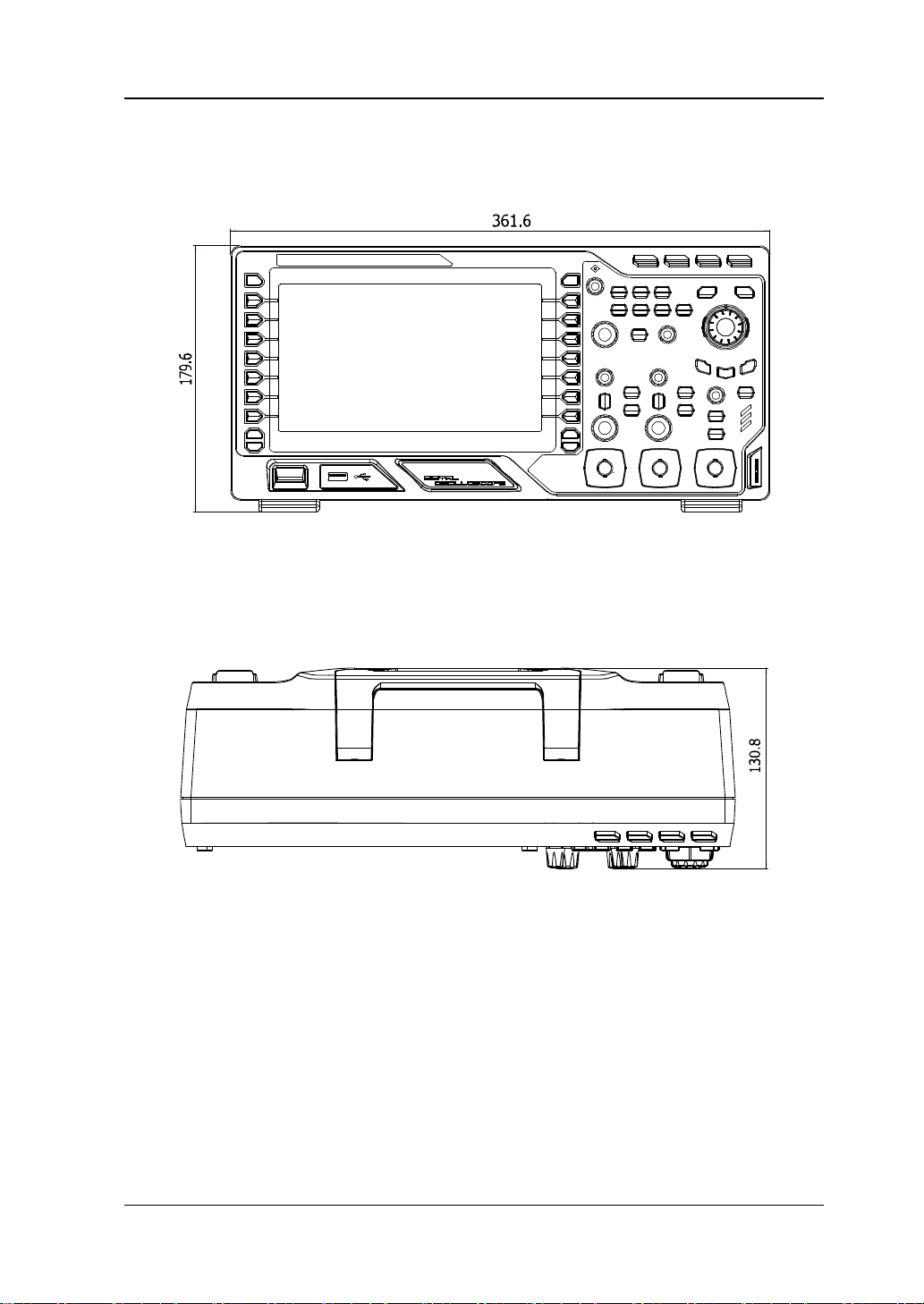
Appearance and Dimensions
Figure 1-1 Front View Unit: mm
Figure 1-2 Top View Unit: mm
DS2000A User’s Guide
Page 30

RIGOL 1 Quick Start
1-4
To Prepare the Oscilloscope for Use
To Adjust the Supporting Legs
Adjust the supporting legs properly to use them as stands to tilt the oscilloscope
upwards for stable placement of the oscilloscope as well as better operation and
observation.
Figure 1-3 To Adjust the Supporting Legs
To Connect to Power Supply
The power requirements of the oscilloscope are 100-240 V, 45-440 Hz. Please use
the power cord supplied with th e ac ces sories to connect the oscillo s co pe to the
power source. At this point, the power key at the lower-left corner of the
front panel is in breathing state.
Power Socket
Figure 1-4 To Connect to Power Supply
DS2000A User’s Guide
Page 31

1 Quick Start RIGOL
1-5
Power-on Inspection
When the oscilloscope is energized, press the power key at the lower-left
corner of the front panel to start the osci lloscope. D uring the start-up process, t he
oscilloscope performs a series of self-tests and you can hear the sound of relay
switching. After the self-test, the “Current Options” dialog box will be displayed if
your instrument currently installs the trial versions of opetions. From this dialog box
you can view the types, names, versions and the time left of the options currently
installed. The trial versions of the opetions will be provided when the instrument
leaves factory and the time left is about 2000 minutes.
To Connect the Probe
RIGOL provides passive probes for the DS2000A series oscil l oscopes. For detailed
technical information of the probes, please refer to the corresponding Probe User’s
Guide. The following are the probes recommended for this oscilloscope.
Model Description
RP3300 350 MHz, passive probe, standard
RP3500A 500 MHz, passive probe, optional
Connect the Probe:
1. Connect the BNC terminal of the probe to a channel BNC connector of the
oscilloscope at the front panel.
2. Connect the ground al ligat or c lip of the p robe to the circuit gr ound terminal and
connect the probe tip to the circuit point to be tested.
Figure 1-5 To Connect the Probe
DS2000A User’s Guide
Page 32

RIGOL 1 Quick Start
1-6
o avoid electric shock during the use of probe, please make sure that
Function Inspection
1. Press Storage Default to restore the instrument to its default configuratio n.
2. Connect the ground alligator clip of the probe to the “Ground Terminal” under
the probe compensation signal output terminal.
3. Use the probe to connect the input terminal of CH1 of the oscilloscope and the
“Compensation Signal Output Terminal” of the probe.
Compensation Signal Output Terminal
Ground Terminal
Figure 1-6 To Use the Compensation Signal
4. Press AUTO.
5. Observe the wav eform on the disp lay. In normal condition, the displa y should be
a square waveform as shown in the figure below:
Figure 1-7 Square Waveform
6. Use the same method to test the other channels. If the square waveforms
actually shown do not match that in the figure above, please perform
Compensation in the next section.
WARNING
T
the insulated wire of the probe is in good condition and do not touch
the metallic part of the probe when the probe is connected to high
voltage source.
Probe
DS2000A User’s Guide
Page 33

1 Quick Start RIGOL
1-7
Tip
probe compensation adjustment and can not be used for calibration.
Over compensated Perfectly compensated Under compensated
The signal output from the probe compensation connector can only be used for
Probe Compensation
When the probes are used for the first time, you should compensate the probes to
match the input channels of the oscilloscope. Non-compensated or poorly
compensated probes may c ause measurement inaccuracy or error. The prob e
compensation pro cedur e s are as follows.
1. Perform steps 1, 2, 3 and 4 of
2. Check the waveforms displayed and compare them with the following.
Figure 1-8 Probe Com pensation
3. Use a nonmetallic driver to adjust the low-frequency compensation adjustment
hole on t he prob e until the wavef orm displa yed is as the “Perfectly compensated”
in the figure above.
Function Inspection in the previous section.
DS2000A User’s Guide
Page 34

RIGOL 1 Quick Start
1-8
3 4 5 6 7 8 9 10 11
Front Panel Overview
1 2
12 13 14 15 16 17 18 19 20 21
Figure 1-9 Front Panel Overview
DS2000A User’s Guide
Page 35

1 Quick Start RIGOL
1-9
[1]
Table 1-1 Front Panel Desc ript ion
No. Description No. Description
1 Menu 12 Power Key
2 LCD 13 USB HOST
3 Multi-function Knob 14 HORIZONTAL
4 Function Menu Keys 15 Function Setting Menu Softkeys
5 Signal Generator
16 VERTICAL
6 Navigation Knob 17 Analog Channel Input Area
7 CLEAR 18 Waveform Record/Playback
8 AUTO 19 TRIGGER
9 RUN/STOP 20 EXT TRIG Input Terminal
10
SINGLE
21 Probe Compensation Signal Output
Terminal/Ground Terminal
11 Help&Print -- --
[1]
Note
: Only applicable to DS2000A-S.
DS2000A User’s Guide
Page 36

RIGOL 1 Quick Start
1-10
Rear Panel Overview
1 2 3
4 5 6 7 8
Figure 1-10 Rear Panel Overview
1. Handle
Pull up the handle vertically for easy carrying of the instrument. When you do
not need the handle, press it down.
2. LAN
Connect the instrument to the network via this interface f or remote control. This
oscilloscope conforms to the LXI-C class instrument standards and can quickly
build test system with other instruments.
3. USB DEVICE
PictBridge printer or PC can be connected via this interface to print waveform
data or control the instrument using PC software or user-defined programming.
4. Fuse
If a new fuse is required, please use the specified fuse (250V, T2A).
DS2000A User’s Guide
Page 37

1 Quick Start RIGOL
1-11
a) Turn off the instrument and remove the power cord.
b) Insert a small straight s cre w driv er into the g roove at the p owe r s ocke t and
prize out the fuse seat gently.
c) T ake out the f use and replace it with a s pecified one. R eins tall the fuse s eat.
5. AC Power Socket
AC power input terminal. The power requirements of this oscilloscope are
100-240 V, 45-440 Hz. Use the power cord provided with t h e accesso ries to
connect the instrument to AC power. Then, you can press the power key at the
front panel to start the instrument.
6. Lock Hole
You can lock the instrument to a fixed location using the security lock (please
buy it yourself) via the lock hole.
7. Trigger Out
The oscilloscope outputs a signal that can reflect the current c apture rate of the
oscilloscope at each trigger via this interface. Connect this sig nal t o a waveform
display device to measure the frequency of the signal and the measurement
result should be the same with the current capture rate.
8. Signal Output
When the corresponding signal source 1 or signal source 2 is enabled, the
current signal can be output to the analog channel output terminal of the
oscilloscope or the external device connected via [Source 1] or [Source 2].
This function is only applicable to DS2000A-S.
DS2000A User’s Guide
Page 38

RIGOL 1 Quick Start
1-12
waveforms on the screen and the c hannel input
Front Panel Function Overview
VERTICAL
CH1, CH2: analog input channels. The 2
channels are marked by different colors which
are also used to mark both the corresponding
connectors. Pres s any key to o pe n the
corresponding channel me nu and p ress again t o
turn off the channel.
MATH: press this key to open the math
operation menu under whi ch ad d, subtract, multiply , divide, FFT, logic and advanced
operations are provided.
REF: press this key to enable the reference waveform function to compare the
waveform actually tested with the reference waveform.
Vertical POSITION: modify the vertical position of the current channel
waveform. Turn clockwise to increase the position and turn counterclockwise to
decrease. During the modification, the waveform would move up and down and the
position message (e.g. ) at the lower-left corner of the screen would
change accordingly. Press down this knob to quickly reset the vertical position to
zero.
VERTICAL SCALE: modify the vertical scale of the current channel. Turn
clockwise to decrease the scale and turn counterclockwise to increase. During the
modification, the amplitude of the waveform would enlarge or reduce and the scale
information (e.g. ) at the lower side of the screen would change
accordingly. Press down this knob to quickly switch the vertical scale adjustment
modes between “Coars e” and “Fin e”.
DS2000A User’s Guide
Page 39

1 Quick Start RIGOL
1-13
Decode1, Decode2: decoding function keys. Press the correspondin g key to open
the decoding function menu. DS2000A supports parallel decoding and protocol
decodings.
HORIZONTAL
MENU: press this key to open the
horizontal control menu under which
to turn on or off the delayed sweep
function, switch between different
time base modes, switch between
“Coarse” and “Fine” adjustment of scale as well as modify the horizontal reference
setting.
HORIZONTAL SCALE: modify the horizontal time base. Turn clockwise to
reduce the time base and turn counterclockwise to increase the time base. During
the modification, waveforms of all the channels will be displayed in expanded or
compressed mode and the time base me ssage (e.g. ) at the upper side
of the screen would change accordingly. Press down this knob to quickly switch to
delayed sweep state.
HORIZONTAL POSITION: modify the horizontal position. The trigger point
would move left or right relative to the center of the screen when you turn the knob.
During the modificat ion, w avef orms of all the c hannels would mo ve left or right and
the horizontal position message (e.g. ) at the upper-right corner of
the screen would change accordingly. Pressing down this knob will q uickly reset the
horizontal position (or the delayed sweep position).
DS2000A User’s Guide
Page 40

RIGOL 1 Quick Start
1-14
MODE
Press this k ey to clear all t he wavef orms on the sc reen. If
still be displayed.
Press this key to set the state of the oscilloscope to
TRIGGER
: press this key to switch the trigger mode to
Auto, Normal or Single and the corresponding
state backlight of the current tr i gger mode would
be illuminated.
TRIGGER LEVEL: modify the trigger level .
Turn clockwise to increase the level and turn
counterclockwise to reduce the level. During the
modification, the trigger level line would move up
and down and the value in the trigger level message box (e.g. ) at the
lower-left corner of the screen would change accordingly. Pressing down the knob
will quickly reset the trigger level to zero point.
MENU: press this key to open the trigger operation menu. This oscillos cope provides
various trigger types.
FORCE: in Normal and Single trigger mode s, pres s this key to generate a trigger
signal forcefully.
CLEAR
the oscilloscope is in “RUN” state, new waveforms will
RUN/STOP
“RUN” or “STOP”.
In “RUN” state, the key is illuminated in yellow.
In “STOP” state, the key is illuminated in red.
DS2000A User’s Guide
Page 41

1 Quick Start RIGOL
1-15
according to the input signal t o realize optimum waveform
SINGLE
Press this key to set the trigger mode to “Single”. In
single trigger mode, pres s FORCE to generate a trigger
signal immediately.
AUTO
Press this key to enable the waveform auto setting
function. The oscilloscope will automatically adjust the
vertical scale, horizontal time base and trigger mode
display. Note that auto setting requires that the frequency
of the signal under test s hould be no lower than 50 Hz, the
duty cycle be greater than 1% and the amplit u de be at
least 20 mVpp. If the parameters exceed these limits,
“Auto failed!” would be displayed after pressing this key
and the quick param eter meas urement menu m ight not b e
displayed.
DS2000A User’s Guide
Page 42

RIGOL 1 Quick Start
1-16
Adjust waveform brightness:
For example, this knob ca n be used to quic kly loca te the w a vef orm fr ame (“ Current
Knob
In non-menu-operation mode (menu is hidden), turn this
knob to adjust the brightness of waveform display. The
adjustable range is from 0% to 100%. Turn clockwise to
increase the brightness and counterclockwise to reduce.
Multifunction Knob (the backlight goes on during operation):
In menu operation, press any menu softkey and turn the knob to switch to the
desired submenu under this menu and then press down the knob to select the
current submenu. It can also be used to modify parameters and input filename.
Besides, for DS2000A-S oscilloscope, when the current operation interface is signal
generator, the numeric keyboard will be dis playe d when you press the corresponding
menu key and press down the kn ob. At this point, you can us e t he knob to inp ut the
desired parameter value and unit directly.
Pressing down this knob w ill reset the brightness to 50%.
You ca n also press Display WaveIntensity and use
the knob to adjust the waveform brightness.
Navigation K n ob
This knob provides quick Adjust/L ocate
function for numerical parameters with
relatively larger settable range. Turn clockwise
(counterclockwise) to increase (reduce) the
value. The inner knob is used for fine
adjustment and the oute r knob for coarse
adjustment。
Frame” menu) to be played back in the waveform playback function. Similar menus
include trigger holdoff, pulse width setting, slope time etc.
DS2000A User’s Guide
Page 43
1 Quick Start RIGOL
1-17
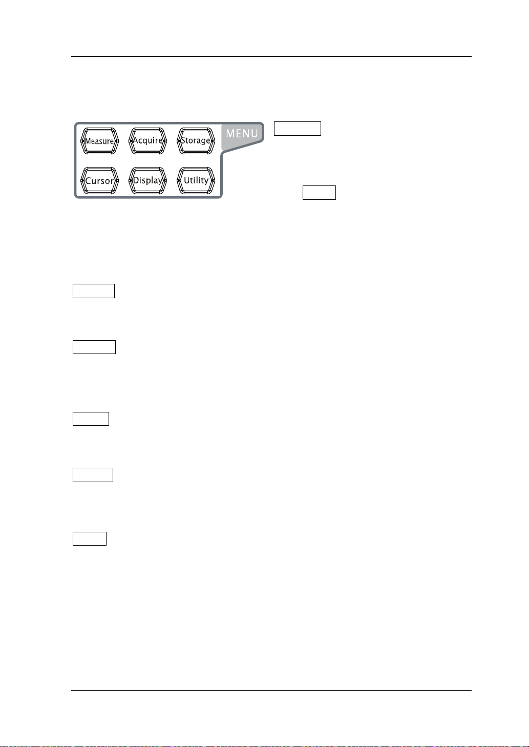
Measure
Menu
: press this key to ope n the
measurement setting menu. You can set
the measurement setting, all measure,
statistic function etc.
Press MENU at the left of the screen
to open the measurement menus of 24 waveform pa rameters. Then, press down the
corresponding menu softkey to quickly realize one-key measurement and the
measurement result will be displayed at the bottom of the screen.
Acquire: press this key to enter the sample setting menu to set the acquisition
mode, memory depth and antialiasing function of the oscilloscope.
Storage: press this key to enter the file store and recall interface. The storable file
types include traces, waveforms, setups, picture and CSV. Internal and external
storage as well as disk management are also supported.
Cursor: press this key to enter the cursor measurement menu. The oscilloscope
provides three cursor modes: manual, track and auto.
Display: press this key to enter the display setting menu to set the display type,
persistence time, wav e intens it y, grid type, grid brightness and m enu disp la y time of
the waveform.
Utility: press this key to enter the system function setting menu to set the
system-related functions or parameters, such as I/O setting, sound and language.
Besides, some advanced functions (such as pass/fail test, waveform record and print
setting) are also supported.
DS2000A User’s Guide
Page 44

RIGOL 1 Quick Start
1-18
Source
Press this key to enter the signal source setting interface. You can
Note: This function is only applicable to DS2000A-S.
turn onor off the outpts of the [Source1] and [Source2]
connectors and set the par ameters of the output s ignal (such as the
frequency, amplitude, offset and phase).
Record
Stop Play/Pause Record
Record: press this ke y to s ta rt rec ord ing th e w a v ef o rm. The bac klight is illuminated
in red. Besides, when record constant on (Open) is enabled, the backlig ht will also be
illuminated.
Play/Pause: in stop or pause state, press this key to play back the waveform and
press again to pause the play. The backlight is illuminated in yellow.
Stop: press this key to stop the waveform being recorded or being played back. The
backlight is illuminated in orange.
DS2000A User’s Guide
Page 45

1 Quick Start RIGOL
1-19
Press this k ey to execute the print f unction or save t he screen in the
USB storage device. If a PictBridge printer is currently connected
and the printer is in idle state, pressing this key will execute the
print function. If no printer but a USB storage device is currently
connected, pressing this key will save the screen to the U SB storage
device in “.bmp” format. If the current storage type is picture, the
screen will be saved in the USB storage device in the specified
picture format (bmp, png, jpeg and ti ff). When printer and USB
storage device are connected at the same time, the printer enjoys
higher priority.
DS2000A User’s Guide
Page 46

RIGOL 1 Quick Start
1-20
User Interface
DS2000A provides 8.0 inches, WVGA (800*480) 160,000 color TFT LCD. What is
worth mentioning is that the 14-grid ultra-wide screen enables you to view “longer”
waveform.
1 2 3 4 5 6 7 8 9 10 11
12 13 14 15 16 17 18
Figure 1-11 User Interface
1. Auto Measurement Items
Provide 12 horizontal (HORIZONTAL) and 12 vertical (VERTICAL) measurement
parameters. Press the softkey at the left of the screen to activate the
corresponding measurement item. Press MENU continuously to switch b etween
the horizontal and vertical parameters.
2. Channel Label/Waveform
Different channels are mar ked by dif f erent colors and the c ol or of the w a v e form
DS2000A User’s Guide
Page 47

1 Quick Start RIGOL
1-21
screen
complies with the color of the channel.
3. Status
Available states include RUN, STOP, T’D (triggered), WAIT and AUTO.
4. Horizontal Time Base
Represent the time per grid on the horizontal axis on the screen.
Use HORIZONTAL SCALE to modify this parameter. The range
available is from 1.000 ns to 1000 s (for 200 MHz bandwidth oscilloscope,
the range is from 2.000 ns to 1000 s; for 100 MHz and 70 MHz bandwidth
oscilloscopes, the range is from 5.000 ns to 1000 s).
5. Sample Rate/Memory Depth
Display the current sample rate and memory depth of the oscilloscope.
Use HORIZONTAL SCALE to modify this parameter.
6. Waveform Memory
Provide the schematic diagram of the memory position of the waveform
currently on the screen.
waveform on the
7. Trigger Position
Display the trigger position of the waveform in the waveform memory and on
the screen.
8. Horizontal Position
Use HORIZONTAL POSITION to mo di fy thi s paramete r. Pressing down
the knob will automatically set the parameter to zero.
9. Trigger Type
Display the trigger type currently selected and trigger condition setting.
Different labels are displayed when different trigger types are selected.
For example: represents triggering on the rising edge in “Edge” trigger.
10. Trigger Source
Display the trigger source currently selected (CH1, CH2, EXT, or AC Line).
Different labels are displayed when different trigger sources are selected and
the color of the trigger parameter area will change accordingly.
For example: denotes that CH1 is selected as the trigger source.
11. Tri gger Level
at the right of the screen is the trigger level label and the trigger level
value is displayed at the upper-right corner of the screen.
When using TRIGGER LEVEL to modify the trigger level, the trigger
level value will change with the up and down of .
DS2000A User’s Guide
Page 48

RIGOL 1 Quick Start
1-22
Note: In slope trigger, runt trigger and windo ws tr i gge r, there are two trigger
level labels ( and ).
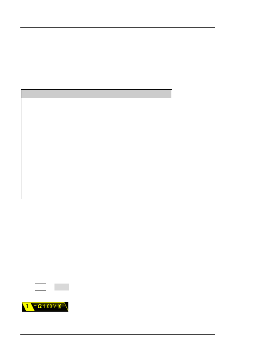
12. CH1 Vertical Scale
Display the voltage value per grid of CH1 waveform vertically.
Use VIRTICAL SCALE to modify this parameter.
The following labels will be displayed according to the current channel
setting: channel coupling (e.g. ), input impeda n ce ( e .g. ) and
bandwidth limit (e.g. ).
13. CH2 Vertical Scale
Display the voltage value per grid of CH2 w aveform vertically.
Use VIRTICAL SCALE to modify this parameter.
The following labels will be displayed according to the current channel
setting: channel coupling (e.g. ), input impedance (e.g. ) and
bandwidth limit (e.g. ).
14. Source 1 Waveform
Display the current waveform type in Src1 Setup.
When the impedance of the source is set to 50 Ω, is displayed at the
right of Source 1 Waveform.
When modulation is turned on, is displayed at the right of Source 1
Waveform.
Only applicable to DS2000A-S.
15. Source 2 Waveform
Display the current waveform type in Src2 Setup.
When the impedance of the source is set to 50 Ω, is displayed at the
right of Source 2 Waveform.
When modulation is turned on, is displayed at the right of Source 2
Waveform.
Only applicable to DS2000A-S.
16. Message Box
Display prompt messages.
17. Notification Area
Display system time, sound icon and USB storage device icon.
System Time: displayed in “hh:mm (hour:minute)” format. When printing
or storing the waveform, the output file will contain this time message.
Press Utility System System Time to set through the following
format:
yyyy-mm-dd hh-mm-ss (year-month-date hour-minute-second)
Sound Icon: when sound is enabled, will be displayed. Press Utility
Sound to enable or disable the sound.
USB Storage device Icon: when a USB storage device is detected, will
be displayed.
DS2000A User’s Guide
Page 49

1 Quick Start RIGOL
1-23
Denote that at the front panel can be used to select parameter
items. The backlight of turns on when parameter selection is valid.
Denote that can be used to modify parameter values. The backlight
of turns on when parameter input is valid.
Denote that can be used to modify parameters and the numeric
when parameter input is valid.
Denote that you can use the
to quickly adjust/locate parameters.
Denote that you can use to adjust the parameter and then press
down to select the parameter.
Denote that the current menu has several options.
Denote that the current menu has a lower level menu.
Press this key to return to the previous menu.
Note: The following direction keys might appear in the grid at the lower-left
corner of the menu bar:
Denote that you can open the next page menu.
Denote that you can open the previous page menu.
18. Operation MENU
Press any softkey to activate the corresponding menu. The following symbols
might be displayed in the menu:
keyboard with which you can input parameter values directly will be
displayed when is pressed do wn . The backlight of turns on
DS2000A User’s Guide
Page 50

RIGOL 1 Quick Start
1-24
To Use the Security Lock
If needed, you can use the security lock (please buy it yourself) to lock the
oscilloscope to a fixed locat ion. The me thod is as f oll ows, align the l ock with th e l ock
hole and plug it into the lock hole vertically, turn the key clockwise to lock the
oscilloscope and then pull the key out.
Figure 1-12 To Use the Security Lock
Note: Do not insert any other articles into the security lock hole to avoid damaging
the instrument.
Security Lock
Hole
DS2000A User’s Guide
Page 51

1 Quick Start RIGOL
1-25
To Use the Built-in Help System
The help system of this oscilloscope provides instructions for all the function keys
(including menu keys) at the f ront p anel . P res s Help to open the help interface and
press again to close the inter face . The help interface mainly consists of two parts.
The left is “Help Options” and you can use “Button” or “Index” mode to select. The
right is “Help Display Area”.
Help Options Help Display Area
Figure 1-13 Help Information
Button:
Default mode. In this mode, you can press the button (except the pow e r key ,
the knob and th e men u page up/do w n key / ) or rotate the navigation
knob at the front panel directly to get the corresponding help information in the
“Help Display Area”.
Use to select “To Index” and then press the knob to switch to Index mode.
Index:
In this mode, use to select the desired item (for example, “Band Width”). The
item currently selected is displayed in brown. Press the knob to get the
corresponding help information in the “Help Display Area”.
Use to select “To Button” and then press the knob to switch to Button mode.
DS2000A User’s Guide
Page 52

Page 53

2 To Set the Vertical System RIGOL
2-1
2 To Set the Vertical System
The contents of this chapter:
To Enable the Channel
Channel Coupling
Bandwidth Limit
Probe Ratio
Input Impedance
Waveform Invert
Vertical Scale
Vertical Expansion
Amplitude Unit
Channel Label
Delay Calibration
DS2000A User’s Guide
Page 54

RIGOL 2 To Set the Vertical System
2-2
To Enable the Channel
DS2000A provides 2 analog input c hannels (CH1 and CH2) and provides independent
vertical control system for each channel. As the vertical system setting methods of
the 2 channels are completely the same, this chapter takes CH1 as an example to
introduce the setting method of the vertical system.
Connect a signal to the channel connector of any channel (for example, CH1) and
then pre ss CH1 in the vertical control area (VERTICAL) at the front panel to enable
CH1.
Screen:
The channel setting menu is disp layed at the right side of the screen and the channel
label at the bottom of the screen (as shown in the figure below) is highlighted. The
information displayed in the channel label is related to the current channel setting.
After the channel is turned on, modify the parameters such as the vertical scale,
horizontal time base and trigger mode according to the input signal to make the
waveform display easy to observe and measure.
DS2000A User’s Guide
Page 55

2 To Set the Vertical System RIGOL
2-3
Channel Coupling
The undesired s ignals can be filtered out by s etting the coupling mode. For example,
the signal under test is a square waveform with DC offset.
When the coupling m ode is “DC”: the DC and AC components of the sig nal under
test can both pass the channel.
When the coupling mode is “AC”: the DC components of the signal under test
are blocked.
When the coupling mode is “GND”: the DC and AC components of the signal
under test are both blocked.
Press CH1 Coupling and use to select the desired coupling mode (the
default is DC). The current coupling mode is displayed in the channel label at the
bottom of the screen. You can also pr ess Coupling continuously to switch the
coupling mode.
Bandwidth Limit
Setting the bandwidth limit can reduce the display noise. For example, the signal
under test is a pulse with high frequency oscillation.
When bandwidth limit is disabled, the high frequency components of the signal
under test can pass the channel.
Enable bandwidth limit and limit the bandwidth to 20 MHz or 100 MHz (only
applicable to 200 MHz and 300 MHz oscilloscopes), the high frequency
components that exceed 20 MHz or 100 MHz are attenuated.
Note: for DS2102 and DS2072, the bandwidth limit can only b e set to 20 MHz.
Press CH1 BW Limit and use to enable or disable bandwidth limit (the
default is OFF). When bandwidth limit (20 MHz or 100 MHz) is e nabled, the cha racter
“B” will be displayed in the channel label at the bottom of the screen. You can also
press BW Limit continuously to switch between on and off of the bandwidth limit.
DS2000A User’s Guide
Page 56
RIGOL 2 To Set the Vertical System
2-4
0.01X
1000X
1:100
1000:1
Probe Ratio
You can set the probe attenuation ratio manually. The probe ratio values available
are as shown in the table below.
Table 2-1 Probe Attenuation Coefficient
Menu Attenuation Coefficient
0.02X
0.05X
0.1X
0.2X
0.5X
1X
2X
5X
10X
20X
50X
100X
200X
500X
1:50
1:20
1:10
1:5
1:2
1:1
2:1
5:1
10:1
20:1
50:1
100:1
200:1
500:1
Input Impedance
This coscilloscope provides two input impedance modes (1 MΩ (default) and 50 Ω) to
reduce the circuit load c aus ed by the inte ract ion of t he oscill oscope and the circ uit to
be tested.
1 MΩ: the input impedance of the oscilloscope is rather high and the current
flowing into the oscilloscope from the circuit under test can not be ignored.
50 Ω: match the oscilloscope with a device with 50 Ω output impedance.
Press CH1 Input to set the inp ut impedance of the oscillos cope. When “50 Ω” is
selected, “Ω” is displayed in the channel label at the bottom of the screen.
DS2000A User’s Guide
Page 57

2 To Set the Vertical System RIGOL
2-5
Waveform Invert
When waveform invert is enabled, the waveform display rotates 180 degree relative
to the ground potential. When waveform invert is disabled, the wav e fo rm display is
normal. Press CH1 Invert to enable or disable waveform invert.
Vertical Scale
The vertical scale can be adjusted in “Coarse” or “Fine” mode.
Press CH1 Volts/Div to s elect the desired mode. Rotate VERTICAL SCALE
to adjust the vertical scale (clockwise to reduce the scale and counterclockwise to
increase).
The scale information (such as ) in the channel label at the
bottom of the screen will change accordingly during the adjustment. The adjustable
range of the vertical scale is related to the probe ratio currently set. By default, the
probe ratio is 1X and the adjustable range of the vertical scale is from 500 μV/div to
10 V/div.
Coarse adjustment (take counterclockwise as an example): set the vertical scale
in 1-2-5 step namely 5 00 μV/div, 1 mV/div, 2 mV/div, 5 mV/div, 10 mV/div…10
V/div.
Fine adjustment: further adjust the vertical scale within a relatively smaller
range to improve v e rtical r es olution. If the am plitud e of the input waveform is a
little bit greater than the full scale under the current scale and the amplitude
would be a little bit lower if the next scale is used, fine adjustment can be used
to improve the amplitude of waveform display to view signal details.
Note: You can also press VERTICAL SCALE to quickly switch between “Coarse”
and “Fine” adjustments.
DS2000A User’s Guide
Page 58
RIGOL 2 To Set the Vertical System
2-6
Vertical Expansion
When using VERTICAL SCALE to change the vertical scale of the analog
channel, you can choose to expand or compress the signal vertically around the
center of the screen or the ground point of the signal.
Press Utility System VerticalExp to select “Center” or “Ground” and the
default is “Ground”.
Center: when the vertical scale is modified, the waveform will expand or
compress around the center of the screen.
Ground: when the vertical scale is modified, the waveform ground level will
remain at the same point on the screen and the waveform will expand or
compress around this point.
Amplitude Unit
Select the amplitude dis play unit f or the cur rent channel. The av ailable units a re W, A,
V and U. When the unit is changed, the unit displayed in the channel label will
change accordingly.
Press CH1 Unit to select the desired unit and the default is V.
DS2000A User’s Guide
Page 59
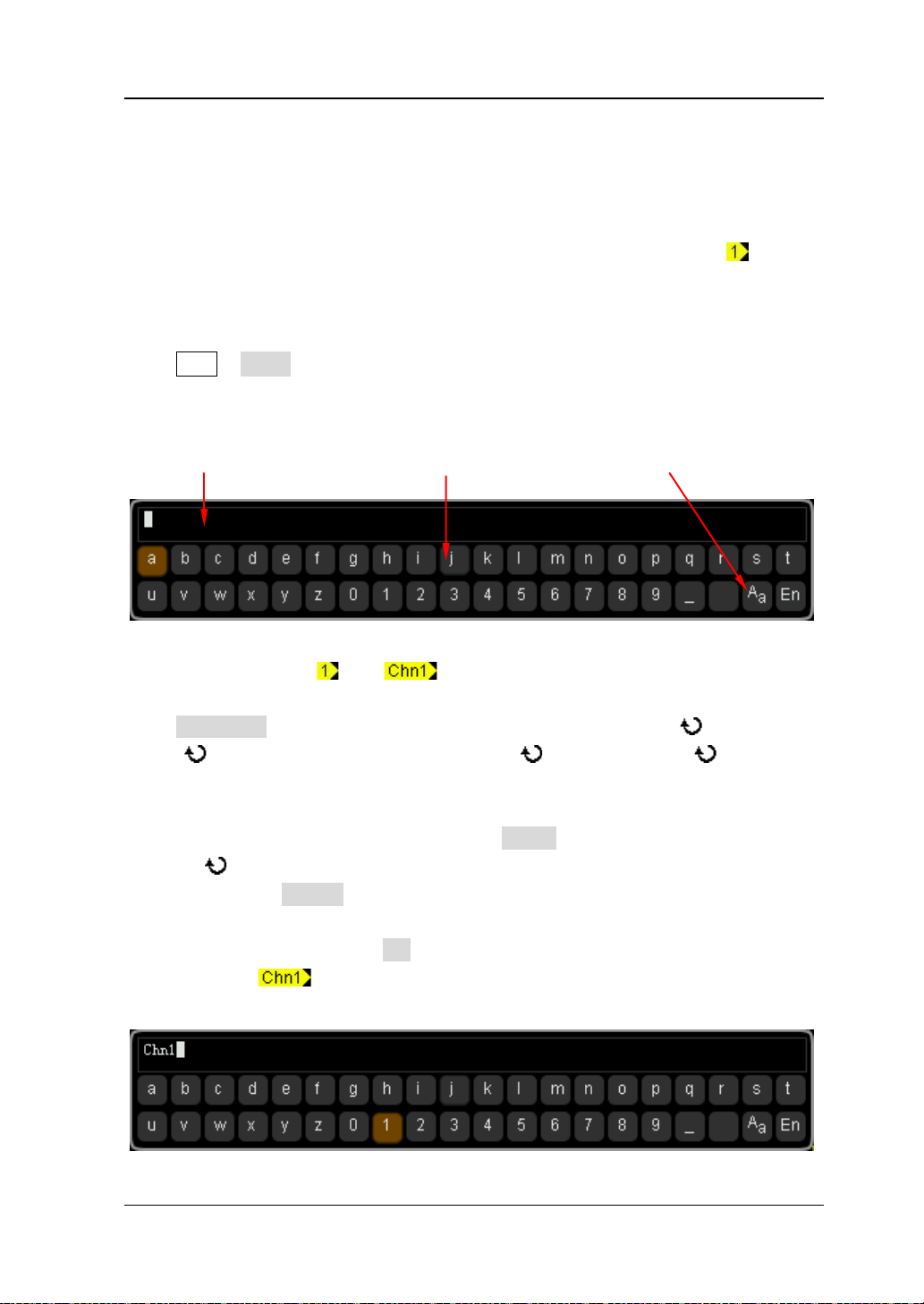
2 To Set the Vertical System RIGOL
2-7
Channel Label
You can modify the labels used to mark the analog channels (CH1 and CH2) at the
left side of the screen. The label is the number of the channel (such as ) by
default and the length of the label can not exceed 4 characters. Note: Only English
input method can be used for this operation.
Press CH1 Label to enter the label modification interface as shown in the figure
below.
Name Input Area Keyboard Upper/Lower Case Switch
For example, change “ ” to “ ”.
Press Keyboard to select the “Keyboard” area. Select “Aa” using and press
down to switch it to “
a
A”. Select “C” using and press down to input the
character. Use the same method to input “hn1”.
T o modify or delete the input character, press Name to select the “Name Input Area”
and use to select the character to be modified or deleted. Enter the desired
character or press Delete to delete the character selected.
After finishing the input, press OK to finish the modification and the channel label
will change to “ ”.
DS2000A User’s Guide
Page 60

RIGOL 2 To Set the Vertical System
2-8
Delay Calibration
When using an oscilloscope for actual measurement, the transmission delay of the
probe cable may bring relatively greater error (zero offset). DS2000A allows users to
set a delay time to calibrate the zero offset of the corresponding channel. Zero offset
is defined as the offset of the crossing point of the waveform and trigger level line
relative to the trigger position, as shown in the figure below.
Press CH1 Delay-Cal and use to set the desired delay time. The range
available is from -200 ns to 200 ns.
Note: This parameter is related to the instrument model and the current horizontal
scale setting. The larger the horizontal scaleis, the larger the scale will be.
DS2000A User’s Guide
Page 61

3 To Set the Horizontal System RIGOL
3-1
3 To Set the Horizontal System
The contents of this chapter:
Delayed Sweep
Time Base Mode
Horizontal Scale
Horizontal Reference
DS2000A User’s Guide
Page 62
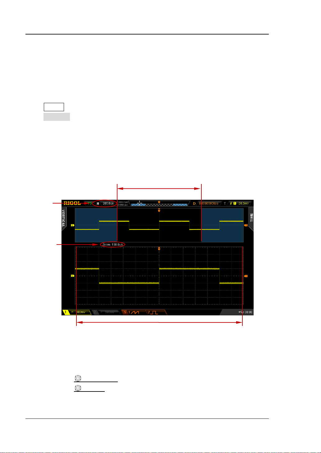
RIGOL 3 To Set the Horizontal System
3-2
enlargement
Delayed Sweep
Delayed sweep can be us ed to enla rge a leng th of waveform horizontally t o view the
waveform details.
Press MENU in the horizontal control area (HORIZONTAL) at the front panel and
press Delayed to enable or disable delayed sweep. Note that to enable delayed
sweep, the current time base mode must be “Y-T” and the “Pass/Fail test” must be
disabled.
In delayed sweep mode, the screen is divided into two display areas as shown in the
figure below.
Main time
base
Delayed
Sweep
Time Base
The waveform before
The waveform after enlargement
The waveform before enlargement:
The waveform in the area that has not been covered by the subtransparent blue in
the upper part of the screen is the waveform before enlargement. You can turn
HORIZONTAL POSITION
HORIZONTAL SCALE
to move the area left and right or turn
to enlarge or reduce this area.
DS2000A User’s Guide
Page 63
3 To Set the Horizontal System RIGOL
3-3
Tip
to directly switch to delayed sweep mo de.
The waveform after enlargement:
The waveform in the l ower part of the screen is the h orizontally expand ed wa veform.
Note: Compared to the main time base, the delayed time base has increased the
waveform resolution (as shown in the figure above). The delayed time base should
be less than or equal to the main time base.
You can also press down HORIZONTAL SCALE (delayed sweep shortcut key)
DS2000A User’s Guide
Page 64

RIGOL 3 To Set the Horizontal System
3-4
The signal must be
Time Base Mode
Press MENU in the horizontal control area (HORIZONTAL) at the front panel and
then press Time Base to select the time base mode of the oscilloscope and the
default is Y-T.
Y-T Mode
This mode is the main time base mode and is applicable to both of the input
channels.
In this mode, the Y a xis rep resents volt age and the X axis represents time. Note that
only when this mode is enabled can
X-Y Mode
Delayed Sweep be turned on.
In this mode, the oscilloscope changes the two channels from voltage-time display
mode to voltage-voltage display mode. Wherein, the X axis and Y axis tracks the
voltages of CH2 and CH1 respectively. The phase deviation between two s ignals with
the same frequency can be easily measured via Lissajous method. The figure below
shows the measurement schematic diagram of the phase deviation.
D
centered horizontally
II I
B
A
C
III IV
DS2000A User’s Guide
Page 65

3 To Set the Horizontal System RIGOL
3-5
According to sinθ=A/B or C/D (wherein, θ is the phase deviation angle between
the two channels and the definitions of A, B, C and D are as shown in the figure
above), the phase deviation angle is obtained, that is:
θ=±arcsin (A/B) or ±arcsin( C/ D)
If the principal axis of the ellipse is within quadrant I and III, the phase deviation
angle obtained should be within quadr ant I and IV, namely within (0 t o π/2) or (3π/2
to 2π). If the principal axis of the ellipse is within quadrant II and IV, the phase
deviation angle obtained s hould be wit hin quad r ant II and II I, name ly within (π/2 to
π) or (π to 3π/2).
X-Y function can be used to measure the phase deviation occurred when the signal
under test passes through a c ircuit network. Connect the oscilloscope to the circuit to
monitor the input and output signals of the circuit.
Application example: measure the phase deviation of the input signals of two
channels.
Method 1: Use Lissajous method
1. Connect a sine signal to CH1 and then connect a sine signal with the same
frequency and amplitude but a 90° phase deviation to CH2.
2. Press AUTO and enable X -Y mode. Rotate Horizontal SCALE to ajdust the
sample rate properly to get better Lissajous figure for better observation and
measurement.
3. Roate VERTICAL POSITION of CH1 and CH2 to display the signals at the
center of the screen and roate VERTICAL SCALE
of CH1 and CH2 to make
the signals easy to observe. At this point, the circle as shown in the fig ure b elow
should be displayed.
DS2000A User’s Guide
Page 66

RIGOL 3 To Set the Horizontal System
3-6
4. As shown in the figure abo v e, t he dis tances from the c ros sing points of a xis an d
the circle to the origin of the coordinates are approximately equal. Thus, the
phase deviation angle
θ=±arcsin1=90°.
Note:
In Y -T mode, the oscilloscope could use any sa mpl e rate (wit hin the guaranteed
range) to capture waveform. The maximum samp l e rate of X-Y mode is 1.0
GSa/s. Generally, reducing the sample rate properly could improve the display
effect of Lissajous figure.
When X-Y mode is enabl e d,
Delayed Sweep will be disabled automatically.
The following functions are not available in X-Y mode:
Auto measure, cursor measure, math operation, reference waveform, delayed
sweep, vector display, HORIZONTAL POSITION
, trigger c on t rol, memory
depth, acquisition mo de , Pass/Fail test and waveform record.
Method 2: Use the shortcut measurement function
Please refer to “Phase A→B ” and “Phase A→B ” measurement functions of “Delay
and Phase” in page
6-15.
DS2000A User’s Guide
Page 67

3 To Set the Horizontal System RIGOL
3-7
Slow Sweep
s, the instrument continues to finish the wa veform at the rig ht
signal, it is recommended that the Channel Coupling is set to “DC”.
Roll Mode
In this mode, the waveform s crolls from the right to the left to update the display and
the waveform horizontal position and trigger control are not available. The range of
horizontal scale adjustment is from 200.0 ms to 1000 s.
Note: When Roll mode is enabled,
Pass/ Fail Test, Measurement Range, Waveform Record, To Set the
Persistence Time and To Trigger the Oscilloscope are not available.
Another mode similar to R oll m ode. When the ho rizo ntal tim e base is s et to 200 ms
or slower, the instrument enters “slow sweep” mode in which the instrument first
acquires the data at the left of the trigger point and then waits for trigger event.
After the trigger occur
of the trigger point. When slow sweep mode is used to observe low frequency
Delayed Sweep, Protocol Decoding,
DS2000A User’s Guide
Page 68

RIGOL 3 To Set the Horizontal System
3-8
Horizontal Scale
Being similar to
“Fine” mode.
Press MENU ScaleAdjust in the horizontal control area (HORIZONTAL) at the
front panel to select the desired mode. Turn HORIZONTAL SCALE to ad j ust
the horizontal scale. Turn clockwise to reduce the horizontal scale and turn
counterclockwise to increase.
The scale information (s uch as ) at the upper left corner of the screen
will change accordingly during the adjustment. The range of horizontal scale
adjustment is from 1.000 ns to 1000 s (for 200 MHz bandwidth oscilloscope, the
range is from 2.000 ns to 1000s; for 100 MHz and 75 MHz bandwidth oscil l o sc opes,
the range is from 5.000 ns to 1000 s).
Coarse (take counterclockwise as an example): set the horizontal scale in 1-2-5
step namely 1 ns、2 ns、5 ns、10 ns…1.000 ks.
Fine: further adjust within smaller range.
Vertical Scale, the horizontal scale can be adjusted in “Coarse” or
DS2000A User’s Guide
Page 69

3 To Set the Horizontal System RIGOL
3-9
Horizontal Reference
Horizontal reference is the reference position according to which the screen
waveform expands or compresses horizontally when ad justing HORIZONTAL
SCALE. In Y-T mode (this function is not a vailable in X -Y mode and Roll mode), press
MENU HorRef in the horiz onta l c ontrol a rea (HO RIZ ONTAL) at the front panel to
select the desired reference mode and the default is “Center”.
1. Center
When changing the ho riz o nt al t ime base, the waveform expands or compres ses
horizontally around the center of the screen.
2. Trig Pos
When changing the horiz o nt al t im e b ase, the waveform e xpand s or compresses
horizontally around the trigger point.
3. User
When changing the ho riz o nt al t im e b ase, the waveform e xpand s or compresses
horizontally around the user-defined reference position. In the horizontal
direction, the screen can display a maximum of 700 points with the leftmost as
350 and the rightmost as -350. For example, set the reference position to 150.
DS2000A User’s Guide
Page 70

Page 71

4 To Set the Sample System RIGOL
4-1
4 To Set the Sample System
The contents of this chapter:
Acquisition Mode
Sample Mode
Sample Rate
Memory Depth
Antialiasing
DS2000A User’s Guide
Page 72

RIGOL 4 To Set the Sample System
4-2
Acquisition Mode
The acquisition mode is used to control how to generate waveform points from
sample points.
Press Acquire Acquisition in the function menu at the front panel and use
to select the desired acquisition mode (the default is normal), then press down the
knob to select this m ode. You can also press Acquisition continuously to s witch the
acquisition mode.
Normal
In this mode, the oscilloscope s ampl es the sig nal at eq ual time int erval to reb uild t he
wavef orm. For mos t of the wa veforms, the best display e ffect can be obtained using
this mode.
Average
In this mode, the oscilloscope averages the waveforms from multiple samples to
reduce the rand om noise of the input signal and improve t he vertical resolution. The
greater the number of averages is, the lower the noise will be and the higher the
vertical resolution will be but the slower the response of the displayed waveform to
the waveform changes will be.
The available rang e of the number of ave rages i s from 2 to 8192 a nd the def ault is 2.
When “Average” mode is selected, press Averages and use to set the desired
number of averages as the power function of 2.
DS2000A User’s Guide
Page 73

4 To Set the Sample System RIGOL
4-3
The Waveform before Average:
The Waveform after 256 Averages:
DS2000A User’s Guide
Page 74

RIGOL 4 To Set the Sample System
4-4
Peak Detect
In this mode, the oscilloscope acquires the maximum and minimum values of the
signal within the samp le interval to g et the envelop e of the sig nal or the narrow pulse
of the signal that mi g ht b e lost. In this mode, sig nal confusion can be prev ent ed but
the noise displayed would be larger.
In this mode, the oscilloscope can displa y all t he pulses with pulse widths at least as
wide as the sample period.
High Resolution
This mode uses a kind of ultra-sample technique to average the neighboring points
of the sample w aveform to reduce the random n oise on the input signal a nd generate
much smoother waveforms on the screen. This is generally used when the sample
rate of the digital converter is higher than the stor age rate of the acquisit ion memory.
Note: “Average” and “High Res” modes use different averaging methods. The former
uses “Multi-sample Average” and the latter uses “Single Sample Average”.
DS2000A User’s Guide
Page 75
4 To Set the Sample System RIGOL
4-5
Tip
to stop the sample, the oscilloscope will hold the las t disp lay. At
zoom the waveform.
Sample Mode
This oscilloscope only supports real-time sample. In this mode, the oscilloscope
samples and displays waveform within a trigger event. The maximum real-time
sample rate of DS2000A is 2 GSa/s and the current sample rate is displayed under
the Sa Rate menu.
Press RUN/STOP
this point, you can still use the vertical control and horizontal control to pan and
DS2000A User’s Guide
Page 76

RIGOL 4 To Set the Sample System
4-6
Sample Rate
The sample rate of this oscilloscope is up to 2 GSa/s. Note that the sample rate is
displayed in the status bar at the upper side of the screen and in the Sa Rate menu
and can be changed by adjusting the horizontal time base (s/div) through
HORIZONTAL SCALE
The influence on the waveform when the sample rate is too low:
1. Waveform Distortion: when the sample rate is too low, some waveform
details are lost and the waveform displayed is rather different from the actual
signal.
or modifying the Memory Depth.
2. Waveform Confusion: when the sample rate is lower than twice the actual
signal frequency (Nyquist Frequency), the frequency of the waveform rebuilt
from the sample da ta is lower than the actual signal frequency. The most
common aliasing is the jitter on fast edge.
DS2000A User’s Guide
Page 77
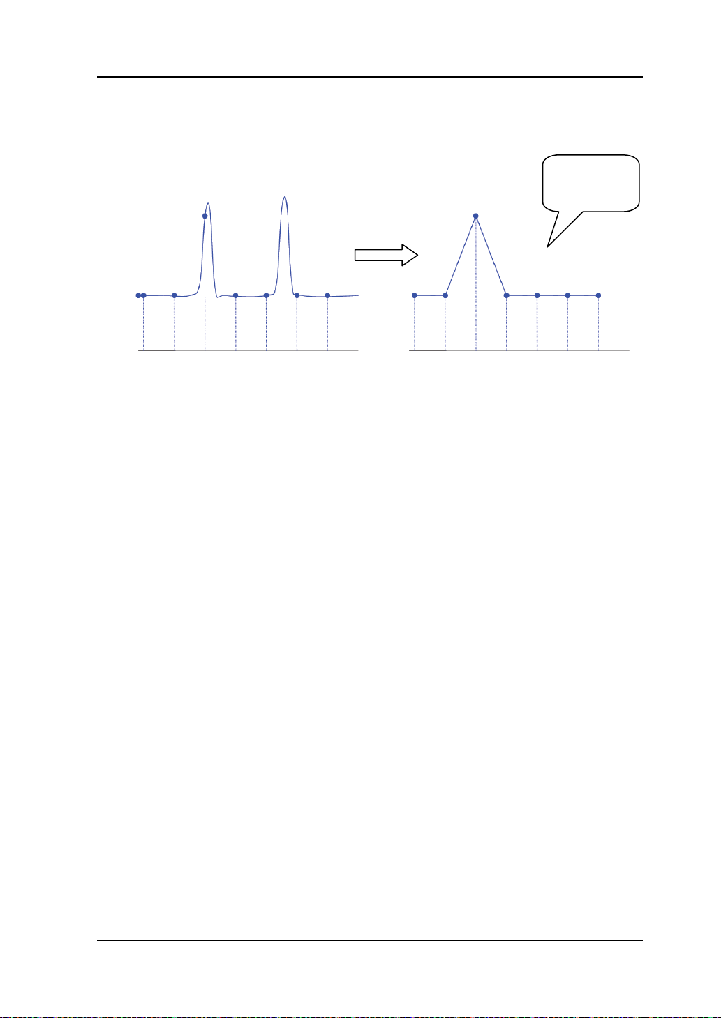
4 To Set the Sample System RIGOL
4-7
3. Waveform Leakage: when the sample rate is too low, the waveform rebuilt
from the sample data does not reflect all the actual signal information.
Pulse
disappeared
DS2000A User’s Guide
Page 78
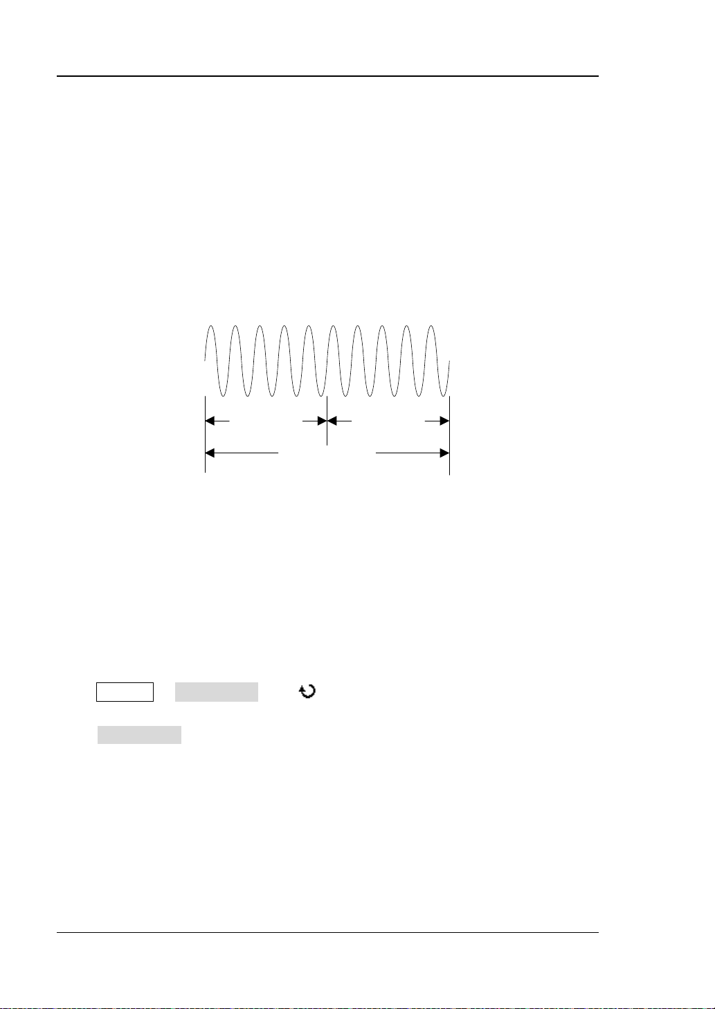
RIGOL 4 To Set the Sample System
4-8
T
Trigger Point
Pre-sample
Delayed Sample
Memory Depth
Memory Depth
Memory depth refers to the number of waveform points that the oscilloscope can
store in a single trigger sample and it reflects the storage ability of the sample
memory. DS2000A provides up to 56 Mpts memory depth (option) an d 14 Mpts
standard memory depth.
The relation of memory de pth, sa mple ra te and w avef orm length f ulfills the equation
below:
Memory depth = sample rate (Sa/s) × waveform length (s/div × div)
Therefore, under the same timebase scale, higher memory depth can ensure higher
sample rate.
Press Acquire Mem Dep th, use to switch to the desired memory depth (the
default is auto) and then press down the knob to select the option. You can also
press Mem Depth continuously to switch the memory depth.
When a single channel is enabled, the memory depths available include Auto,
14kPoints, 140kPoints, 1.4MPoints, 14MPoints and 56MPoints (option). In “Auto”
mode, the oscilloscope selects the memory depth a uto mat ic al l y according to the
current sample rate.
When CH1 and CH2 are enabled, the memory dep ths availab le include Auto, 7kPoints,
DS2000A User’s Guide
Page 79

4 To Set the Sample System RIGOL
4-9
70kPoints, 700kPoints, 7MPoints and 28MPoints (option). In “Auto” mode, the
oscilloscope selects the m emory depth aut omatically acc ording to the current sample
rate.
Antialiasing
At slower sweep speed, the sample rate is reduced and a dedicated display algorithm
is used to minimize the possibility of aliasing.
Press Acquire Anti_Aliasing to enable or disable the antialiasing function. By
default, ant ialiasing is disabled. The displayed waveforms will be more susceptible to
aliasing when this function is disabled.
DS2000A User’s Guide
Page 80

Page 81

5 To T rigger the Oscilloscope RIGOL
5-1
5 To Trigger the Oscilloscope
For trigger, you set cer ta i n tr i gger condition according to the requirement and when
a waveform in the waveform stream meets this condition, the oscilloscope captures
this wavef orm as well as the neighb ouring p art and displays them on the sc reen. For
digital oscilloscope, it displays waveform continuously no matter whether it is stably
triggered, but only stable trigger can ensures stable display. The trigger circuit
ensures that every time base sweep or acquisition starts from the input signal and
the user-defined trigger condition, namely every sweep is synchronous to the
acquisition and the waveforms acquired overlap to display stable waveform.
T rigger setting should be based on the features of the input signal, thus you n eed to
have some knowledge of the signal under test to quickly capture the desired
waveform. This oscilloscope provides abundant adv anced trigger func tions which can
help you to focus on the desired waveform details.
The contents of this chapter:
Trigger Source
Trigger Mode
Trigger Coupling
Trigger Holdoff
Noise Rejectio
Trigger Type
Trigger Output Connector
DS2000A User’s Guide
Page 82

RIGOL 5 To T rigger the Oscilloscope
5-2
Trigger Source
Press MENU Source in the trigger control area (TRIGGER) at the front panel to
select the desired trigger source. Siganls input from CH1/CH2 and the [EXT TRIG]
connector as well as the AC Line can all be used as trigger sou rce.
Analog channel input:
Signals input from analog channels CH1 and CH 2 can all be used as the trigger
source. No matt er w he the r the input of the channe l s elected is enabled, the c hannel
can work normally.
External trigger input:
External trigger source can be used to connect external trigger signal to the EXT
TRIG channel when both of the two channels are sampling data. The trigger sig nal
(such as external clock and signal of the circuit to be tested) will be connected to
EXT trigger s ource via the [EXT TRIG] connector. You can set the trigger condition
within the range of trigger level (-4 V to +4 V).
AC line:
The trigger signal is obtained from the AC power input of the oscilloscope. This kind
of signal source can be used to display the relationship between signal (such as
illuminating device) and p ower ( power s upply d evic e). For example, to stably trigger
the waveform output from the transformer of a transformer substation, which is
mainly used in related measurement of the power industry.
DS2000A User’s Guide
Page 83

5 To T rigger the Oscilloscope RIGOL
5-3
Trigger Mode
Trigger mode affects the way in which the oscilloscope searches for the trigger. The
following is the schematic diagram of the acquis ition mem ory. As shown in the fig ure
below, the position of the trigger ev ent is determined by the reference time point and
the delay setting. Note that the acquisition memory of the oscilloscope is a cyclic
buffer and the new data would overwrite the old data until the acquisition finishes.
Pre-trigger Buffer Post-trigger Buffer
Acquisition memory
Pre-trigger/Delayed trigger:
Acquire data before/after the trigger event. The trigger position is usually at the
horizontal center of the screen. In full-screen display, seven-grid pre-trigger and
delayed trigger informati on are displayed r espectively. You can adjust the horizontal
position of the waveform through HORIZONTAL POSITION
pre-trigger information and delayed trigger information, through which the signal
information before/after the trigger (such as capture the glitch generated by the
circuit and analyze the pre-trigger data to find out the reasons for glitch) can be
obtained.
Press MODE in the trigger control area (TRIGGER) at the front panel or press
MENU Sweep to s elect the desired trigger mode. The corresponding st atus light
of the mode currently selected turns on.
Auto:
No matter whether the trigger condition is met, there is always waveform display. A
horizontal line is displayed when no signal is input.
In this mode, the oscilloscope operates by first filling the pre-trigger buffer. It starts
searching for a trigger after the pre-t rigger buf fe r is filled and c ontinue s t o flo w data
through this buffer while it searches for the trigger. While searching for the trigger,
Trigger Event
to view more
DS2000A User’s Guide
Page 84

RIGOL 5 To T rigger the Oscilloscope
5-4
the oscillos cope ov erflow s t he pre-t rigger b uffer and the first d ata put into the buf fer
is first p ushed out (First Input First Out, FIFO). When a trigger is found, the
pre-trigger buffer would contain the data acquired just before the trigger. If no
trigger is found, the oscilloscop e will trigger forcef ully. If forceful trigger is invalid, the
oscilloscope still displays waveform but the wa v efor m is not s tab le; if forceful trigger
is valid, the oscilloscope displays stable waveform.
This trigger mode is applicable to low-repetitive-rate signals and unknown signal
levels. To display DC signals, you must use a uto trigger mode.
Note: When the horizontal time base is set to 50 ms/div or greater, this trigger mode
allows the absence of trigger signal.
Normal:
Display waveform when the trigger condition is met; otherwise, the oscilloscope
holds the original waveform and waits for the next trigger.
In this mode, the oscilloscope fills the pre-trigger buffer first and then search for a
trigger while at the same time continues filling data. While searching for the trigger,
the oscillos cope ov erflow s t he pre-trigger buffer and the first da ta put into the buf fer
is first pushed out (FIFO). When a trigger is found, the oscilloscope will fill the
post-trigger buffer and display the acquisition memory.
Use normal trigger mode for low-repetitive-rate signals or when auto trigger is not
required.
Note: In this mode, pressing FORCE can generate a trigger signal forcefully.
Single:
When this mode is selected, the backlight of SINGLE turns on. The oscilloscope
waits for a trigger and displays the waveform when the trigger condition is met and
then stops.
Note: In this mode, pressing FORCE can generate a trigger signal forcefully.
DS2000A User’s Guide
Page 85

5 To T rigger the Oscilloscope RIGOL
5-5
Trigger Coupling
Trigger coupling decid es whi ch kind of components will b e transmitted to the trigger
circuit. Please distinguish it with
DC: allow DC and AC components into the trigger path.
AC: block all the DC components and attenuate signals lower than 8 Hz.
LF Reject: block the DC compone n ts an d r e j e ct t h e lo w fr e qu en cy components
(lower than 75 kHz).
HF Reject: reject the high frequency components (higher than 75 kHz).
Press MENU Setting Coupling in the trigger control area (TRIGGER) at the
front panel to select the desired coupling type (the default is DC). Note that trigger
coupling is only valid in edge trigger.
Channel Coupling.
DS2000A User’s Guide
Page 86

RIGOL 5 To T rigger the Oscilloscope
5-6
Trigger Position
Trigger Holdoff
Trigger holdoff can be used to stably trigger the complex waveforms (such as pulse
series). Holdoff time is the amount of time that the oscilloscope waits before
re-arming the trigger circuitry. The oscilloscope will not trigger until the holdoff time
expires.
Holdoff Time
Press MENU Setting Holdoff in the trigger control area (TRIGGER) at the
front panel and use to modify the holdoff time (the default is 100 ns) until the
waveform triggers stably. The adjustable rang e of holdoff time is from 100 ns to 10 s.
Note that trigger hol doff is not available for Nth edge trigger, v i deo trigger, RS232
trigger, I 2 C trigger, SPI trigger an d US B tr i gge r.
DS2000A User’s Guide
Page 87

5 To T rigger the Oscilloscope RIGOL
5-7
Noise Rejection
Noise Rejection adds additional hysteresis to the trigger circuitry. Noise rejection
reduces the possibility of noise trigger but also reduces the trigger sensitivity;
therefore, a larger signal is required to trigger the oscilloscope.
Press MENU Setting Noise Reject in the trigger control area (TRIGGER) at
the front panel to enable or disable noise rejection.
DS2000A User’s Guide
Page 88

RIGOL 5 To T rigger the Oscilloscope
5-8
Trigger Type
DS2000A provides various trigger functions, including various serial bus triggers.
Edge Trigger
Pulse Trigger
Runt Trigger
Windows Trigger (Option)
Nth Edge Trigger
Slope Trigger
Video Trigger (HDTV Option)
Pattern Trigger
Delay Trigger (Option)
TimeOut Trigger (Option)
Duration Trigger (Option)
Setup/Hold Trigger
RS232 Trigger
I2C Trigger
SPI Trigger
USB Trigger (Option)
DS2000A User’s Guide
Page 89

5 To T rigger the Oscilloscope RIGOL
5-9
Edge Trigger
Trigger on the trigger thr eshold of the specified edge of the input signal.
Trigger Type:
Press Type to select “Edge”. At t his point, the trigger set ting information as shown in
the figure below is displayed at the upper right corner of the screen.
Source Selection:
Press Source to select CH1, CH2, EXT or AC Line as the Trigger Source. The
current trigger source is displayed at the upper right corner of the screen.
Note: Select channel with signal input as trigger source to obtain stable tri gger.
Edge Type:
Press Slope to select the kind of edge of the input signal on which the oscilloscope
triggers. The curre n t e dge type is displayed at th e upper right corner of the screen.
: trigger on the rising edge of the inp ut s ignal when the voltag e leve l mee ts
the preset trigger level.
: trigger on t he fal ling ed ge of the inp ut s ignal when the v oltage le vel m eets
the preset trigger level.
: trigger on the rising and falling edges of the input signal when the
voltage level meets the preset trigger level.
Trigger Mode:
Press Sweep to select the Trigger Mode (page 5-3) under this trigg er type as auto,
normal or single. The corresp onding status light o f the current trigg er mode tu rns on.
Trigger Setting:
Press Setting to set the trigger parameters (trigger coupling, trigger hol doff and
noise rejection) under this trigger type.
Trigger Level:
Trigger occurs only when the signal reaches the preset trigger level.
Use TRIGGER LEVEL to modify the level. An orange trigger level line and the
trigger mark “ ” appear on the screen and m o ve up and down with t he rotation of
the knob, while at the same time, the trigger level value (such as ) at the
lower left corner of the screen also changes accordingly. When stopping turning the
DS2000A User’s Guide
Page 90
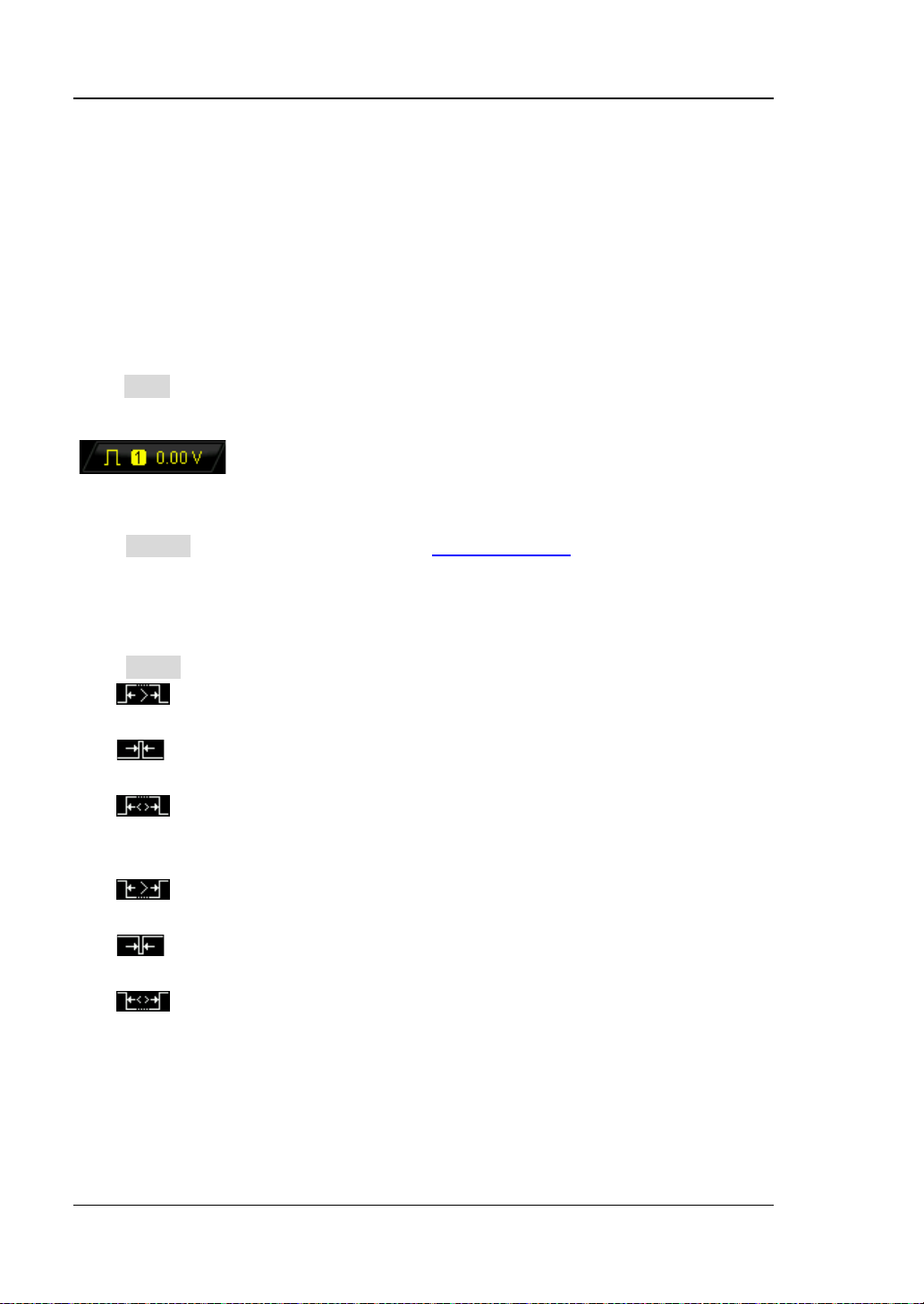
RIGOL 5 To T rigger the Oscilloscope
5-10
knob, the trigger level line and the trigger mark disappea r i n a bout 2 s.
Pulse Trigger
Trigger on the positive or negative pulse with a specified width.
Trigger Type:
Press Type to select “Pulse”. At this point, the trigger s etting informat ion as shown in
the figure below is displayed at the upper right corner of the screen.
Source Selection:
Press Source to select CH1 or CH2 as the Trigger Source. The current trigger
source is displayed at the upper right corner of the screen.
Note: Select channel with signal input as trigger source to obtain stable tr i gger.
Pulse Condition:
Press When to select the desired pulse condition.
: trigger when the positive pulse width of the input signal is great er than
the specified pulse width.
: trigger when the positive puls e width of the input s ignal is lower than t he
specified pulse width.
: trigger when the positive pulse width of the input signal is great er than
the specified lower limit of pulse width and lower than the upper limit of pulse
width.
: trigger when the neg ativ e pulse width of the inp ut signal is greater tha n
the specified pulse width.
: trigger when the negative pulse width of the input signal is lower than
the specified pulse width.
: trigger when the neg ativ e pulse width of the inp ut signal i s greater tha n
the specified lower limit of pulse width and lower than the upper limit of pulse
width.
DS2000A User’s Guide
Page 91

5 To T rigger the Oscilloscope RIGOL
5-11
A
B
Pulse Width Setting:
In this oscilloscope, positive pulse width is defined as the time difference between
the two crossing points of the trigger level and positive pulse as shown in the figure
below.
Trigger level
Positive
pulse width
When the Pulse Condition is set to , , or , p ress
Setting and use to input the desired value. The ran ge availab le is from 2 ns
to 4 s.
When the Pulse Condition is set to or , pr ess Upper Limit
and Lower Limit and use to input the desired values respectively. The
range of the upper limit is from 10 ns to 4 s. The range of the lower limit is from
2 ns to 3.99 s. Note that the lower limit of the pulse width must be lower than
the upper limit.
Trigger Mode:
Press Sweep to select the Trigger Mode (page 5-3) under this trigg er type as auto,
normal or single. The corresponding status light of t he current trigger mode turns on.
Trigger Setting:
Press Setting to set the trigger parameters (trigger holdoff and noise rejection)
under this trigger type.
Trigger Level:
Use TRIGGER LEVEL to modify the level. For details, please refer to the
description of
Trigger Level on page 5-9.
DS2000A User’s Guide
Page 92

RIGOL 5 To T rigger the Oscilloscope
5-12
Runt Trigger
This trigger mode is used to trigger pulses that pass through one trigger level but
fails to pass through the other trigger level as shown in the figure below.
Trigger Type:
Press Type to select “Runt”. At this point, the trigger set ting inf ormation as shown in
the figure below is displayed at the upper right corner of the screen.
Source Selection:
Press Source to select CH1 or CH2 as the Trigger Source. The current trigger
source is displayed at the upper right corner of the screen.
Pulse Polarity:
Press Polarity to select the pulse polarity of runt trigger.
: positive polarity. The instrument triggers on the positive runt pulse.
: negative polarity. The instrument triggers on the negative runt pulse.
Qualifier:
Press Qualifier to set the trigger conditions of runt trigger.
None: do not set the trigger condition of runt trigger.
>: trigger when the runt pulse width is greater than the lower limit of pulse
width. Press Lower Limit to set the minimum pulse width of runt trigger. The
range available is from 2 ns to 4 s.
<: trigger when the runt pulse width is lower than th e upper limit of pulse width.
Press Upper Limit to set the maximum pulse width of runt trigger. The range
DS2000A User’s Guide
Page 93

5 To T rigger the Oscilloscope RIGOL
5-13
available is from 2 ns to 4 s.
<>: trigger when the run t p ulse width is greater than the lower limit and lower
than the upper limit of pulse width. Press Upper Limit to set the maxi mu m
pulse width of runt trigger and the range is from 10 ns to 4 s; pre s s Lower
Limit to s et the m inim um puls e wid th of runt trigg er a nd the ra nge is f rom 2 ns
to 3.99 s.
Note: The lower limit of the pulse width must be lower than the upper limit.
Vertical Window:
Press Vertical to select the desired vertical window type. Note that under the “Runt
trigger” menu, you can press the trigger level knob continuously to switch among
different vertical window types.
You can select the boundary of the trigger level to be set and then use Trigger
LEVEL to adjust the trigger level. During the adjustment, two orange trigger level
lines and trigger marks ( and ) appear on the screen and move up and down
with the rotation of the knob. At the same time, the current trigger level values are
displayed at the lower left corner of the screen. The trigger level lines and trigger
marks disappear after you stop rotating the knob for about 2 s.
The adjustment mode of the trigger level differs when different vertical window is
selected.
: only adjust the upper limit of the trigger level. During the adjustment,
the “Up Level” changes accordingly and “Low Level” remains unchanged.
: only adjust the lower limit of the trigger level. During the adjustment,
the “Low Level” changes accordingly and the “Up Level” remains unchanged.
: adjust the upper and lower limits of the trigger level at the same time.
During the adjustment, the “Up Level” and “Low Level” change accordingly.
Trigger Mode:
Press Sweep to select the Trigger Mode (page 5-3) under this trigg er type as auto,
normal or single. The corresponding status light of t he current trigger mode turns on.
Trigger Setting:
Press Setting to set the trigger parameters (trigger holdoff and noise rejection)
under this trigger type.
DS2000A User’s Guide
Page 94
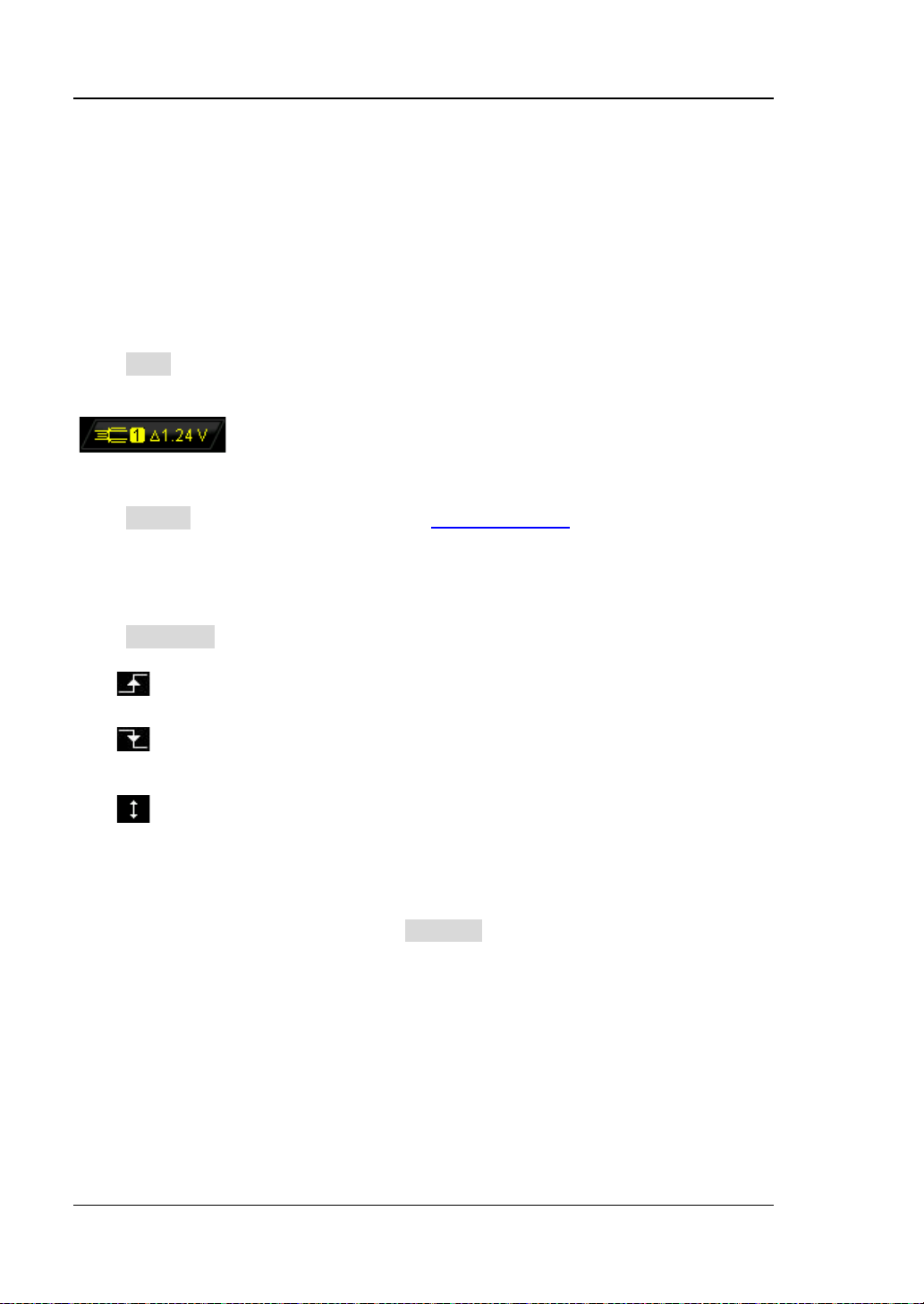
RIGOL 5 To T rigger the Oscilloscope
5-14
Windows Trigger (Option)
Windows trigger provides a hig h t rigge r level and a l ow trigg er lev el. The inst rument
triggers when the input signal pas ses through the high trigger level or the low trigger
level.
Trigger Type:
Press Type to select “Windows”. At this point, the trigger setting information as
shown in the figure below is displayed at the upper right corner of the screen.
Source Selection:
Press Source to select CH1 or CH2 as the Trigger Source. The current trigger
source is displayed at the upper right corner of the screen.
Note: Select channel with signal input as trigger source to obtain stable tri gger.
Windows Type:
Press WndType to select the kind of edge of the input signal on which the
oscilloscope triggers.
: trigger on the rising edge of the input signal when the voltage level is
greater than the preset high trigger level.
: trigger on the falling edge of the input signal when the voltage level is
lower than the preset low trigger level.
: trigger on any edge of the input signal when the voltage level meets the
preset trigger level.
Trigger Position:
After selecting the windows type, press Position to further s pec ify the tim e point of
trigger by selectin g th e t r igger position.
Enter: trigger when the trigger signal enters the specified trigger level range.
Exit: trigger when the input signal exits the specified trigger level range.
Time: used to specify the hold time of the input signal after entering the
specified trigger le vel range. The instrument triggers when the accumulated
hold time equals the windows time.
DS2000A User’s Guide
Page 95
5 To T rigger the Oscilloscope RIGOL
5-15
Vertical Window:
Press Vertical to select the desired vertical w in dow type. For detai l e d o peration ,
referto
Vertical Window:
Press Vertical to select the desired vertical window type. Note that under the “Runt
trigger” menu, you can press the trigger level knob continuously to switch among
different vertical window types.
You can select the boundary of the trigger level to be set and then use Trigger
LEVEL to adjust the trigger level. During the adjustment, two orange trigger level
lines and trigger marks ( and ) appear on the screen and move up and down
with the rotation of the knob. At the same time, the current trigger level values are
displayed at the lower left corner of the screen. The trigger level lines and trigger
marks disappear after you stop rotating the knob for about 2 s.
on page 5-13.
Trigger Mode:
Press Sweep to select the Trigger Mode (page 5-3) under this trigg er type as auto,
normal or single. The corresponding status light of t he current trigger mode turns on.
Trigger Setting:
Press Setting to set the trigger parameters (trigger holdoff and noise rejection)
under this trigger type.
DS2000A User’s Guide
Page 96

RIGOL 5 To T rigger the Oscilloscope
5-16
P1
P2
P3M
P1/P2/P3<Idle Time<M
Edge Type=
Edge Num=2
Nth Edge Trig ger (Option)
Trigger on the nth edge that appears after the specified idle time, as shown in the
figure below.
Trigger Type:
Press Type to select “Nth Edge”. At this point, the trigger setting information as
shown in the figure below is displayed at the upper right corner of the screen.
Source Selection:
Press Source to select CH1 or CH2 as the Trigger Source. The current trigger
source is displayed at the upper right corner of the screen.
Note: Select channel with signal input as trigger source to obtain stable trigger.
Edge Type:
Press Slope to select the kind of edge of the input signal on which the oscilloscope
triggers.
: trigger on the rising ed ge of the input s igna l when the v oltage lev el mee ts
the specified trigger level.
: trigger on the f alling edge of the input signal whe n t he voltag e level meets
the specified trigger level.
Idle Time:
Press Idle to set the idle time before the edge counting in Nth egde trigger. The
range available is from 16 ns to 4 s.
DS2000A User’s Guide
Page 97

5 To T rigger the Oscilloscope RIGOL
5-17
Edge Number:
Press Edge to set the v alue of “N” in Nth edge trigg er and the range av ailable is from
1 to 65535.
Trigger Mode:
Press Sweep to select the Trigger Mode (page 5-3) under this trigg er type as auto,
normal or single. The corresponding status light of t he current trigger mode turns on.
Trigger Setting:
Press Setting to set the trigger parameter (noise rejection) under this trigger type.
Trigger Level:
Use TRIGGER LEVEL to modify the level. For details, please refer to the
description of
Trigger Level on page 5-9.
DS2000A User’s Guide
Page 98

RIGOL 5 To T rigger the Oscilloscope
5-18
Slope Trigger
Trigger on the positive or negative slope of specified time.
Trigger Type:
Press Type to select “Slope”. At this point, the trigger setting information as shown
in the figure below is displayed at the upper right corner of the screen.
Source Selection:
Press Source to select CH1 or CH2 as the Trigger Source. The current trigger
source is displayed at the upper right corner of the screen.
Note: Select channel with signal input as trigger source to obtain stable tri gger.
Slope Condition:
Press When to select the desired slope condition.
: trigger when the positive slope time of the input signal is greater than
the specified time.
: trigger when the positive slope time of the input signal is lower than
the specified time.
: trigger when the positive slope time of the input signal is greater than
the specified lower limit of time and lower than the specified upper lim it of time.
: trigger when the negative slope ti me of the input signal is greater t han
the specified time.
: trigger when the negative slope time of the input signal is lower than
the specified time.
: trigger when the negative slope ti me of the input signal is greater t han
the specified lower limit of time and lower than the specified upper lim it of time.
Time Setting:
In this oscilloscope, positive sl ope time is defined as the t ime dif ference be tween t he
two crossing points of trigger level line A and B with the positive edge as shown in
the figure on the next page.
DS2000A User’s Guide
Page 99

5 To T rigger the Oscilloscope RIGOL
5-19
gValueTimeSettin
LowLevelUpLevel
SlewRate
−
=
imitTimeLowerL
LowLevelUpLevel
~
imitTimeUpperL
LowLevelUpLevel
SlewRate
−−
=
A
B
The upper limit of trigger level (Up Level)
The lower limit of trigger level (Low Level)
Positive
Slope time
When the Slope Condition is set to , , or ,
press Time and use to input the desired value. The range available is from
10 ns to 1 s.
When the Slope Condition is set to or , press Upper Limit
and Lower Limit and use to input the desired values respectively. The
range of time upper limit i s from 20 ns to 1 s . The r ange of the time lowe r limit i s
from 10 ns to 999 ms. Note that the time lower limit must be lower than the
upper limit.
Vertical Window:
Press Vertical to select the desired vertical window. Note that under the “Slope”
trigger menu, you can also press down the trigger level knob continuously to switch
the vertical window.
You can select the boundaries of the trigger level and then use TRIGGER
LEVEL to adjust the trigger level. During the adjustment, two orange trigger level
lines and two trigger marks ( and ) appear on the screen and move up and
down with the rotation of the knob, while at the same time, the trigger level value
and the slope value are displayed at the lower left corner of the screen. When
stopping turning the knob, the trigger level lines and trigger marks disappear in
about 2 s. When the Slope Condition is set t o or , the current
trigger level and slope range will be displayed at the lower left corner of the screen.
The adjustment mode of the trigger level is different when different vertical window
is selected.
DS2000A User’s Guide
Page 100

RIGOL 5 To T rigger the Oscilloscope
5-20
: only adjust the upper limit of the trigger level. During the adjustment,
“UP Level” and “Slew Rate” change acc o rdingly but “Low Level” remains
unchanged.
: only adjust the lower limit of the trigger level. During the adjustment,
“Low Level” and “Sle w Rate” change accordingly bu t “UP Level” remains
unchanged.
: adjust the upper and lower limits of the trigger level at the same time.
During the adjustment, “UP Level” and “Low Level” change accordin gly bu t
“Slew Rate” remains unchanged.
Trigger Mode:
Press Sweep to select the Trigger Mode (page 5-3) under this trigg er type as auto,
normal or single. The corresponding status light of the current trigger mode tu rns on.
Trigger Setting:
Press Setting to set the trigger parameters (trigger holdoff and noise rejection)
under this trigger type.
DS2000A User’s Guide
 Loading...