

Page 1

Performance Verification Guide
DS1000Z-E Series
Digital Oscilloscope
Aug. 2019
RIGOL (SUZHOU) TECHNOLOGIES INC.
Page 2

Page 3

RIGOL
I
Guaranty and Declaration
Copyright
© 2019 RIGOL (SUZHOU) TECHNOLOGIES INC. All Right s Reserved.
Trademark Information
RIGOL is a registered trademark of RIGOL (SUZHOU) TECHNOLOGIES INC.
Publication Number
PVA27100-1110
Notices
RIGOL products are covered by P.R.C. and foreign patents, issued and pending.
RIGOL reserves the right to modify or change parts of or all the specifications and pricing
policies at the company’s sole decision.
Information in this publica ti on re places all previously released materials.
Information in this publication is subject to change without notice.
RIGOL shall not be liable for either incidental or consequential losses in connection with the
furnishing, use, or performance of this manual, as well as any information contained.
Any part of this document is forbidden to be copied, photocopied, or rearranged without prior
written approval of RIGOL.
Product Certification
RIGOL guarantees that this product conf orms to the national and in dustrial standards in China as well
as the ISO9001:2015 standard and the ISO14001:2015 standard. Other international standard
conforman ce ce rt ifications are in progress.
Contact Us
If you have any problem or requirement when using our products or this manual, please contact
RIGOL.
E-mail: service@rigol.com
Website: www.rigol.com
DS1000Z-E Performance Verification Guide
Page 4

RIGOL
II
Safety Requirement
General Safety Summary
Please review the following safety precautions carefully before putting the instrument into operation
so as to avoid any personal injury or damage to the instrument and any product connected to it. To
prevent potential hazards, please follow the instructio ns specified in this manual to use the instrument
properly.
Use Proper Power Cord.
Only the exclusive power cord designed for the instrument and authorized for use within the local
country could be used.
Ground the Instrument.
The instrument is grounded through the Protective Earth lead of the power cord. To avoid electric
shock, connect the earth terminal of the power cord to the Protective Ea rth terminal before connecting
any input or output terminals.
Connect the Probe Correctly.
If a probe is used, the probe ground lead must be connected to earth ground. Do not connect the
ground lead to high voltage. Improper way of connection could result in dangerous voltages being
present on t he c onne ct ors , con t rols or oth e r surf aces of the oscill oscope a nd pro bes, whi ch will cause
potential hazards for operators.
Observe All Terminal Ratings.
To avoid fire or shock hazard, observe all ratings and markers on the instrument and check your
manual for more information about ratings before connecting the instrument.
Use Proper Overvoltage Protection.
Ensure that no overvoltage (such as that caused by a bolt of lightning) can reach the product.
Otherwise, the operator might be exposed to the d anger of an electric shock.
Do Not Operate Without Co v e rs.
Do not operate the instrument with covers o r panels removed.
Do Not Insert Objects Into the Air Outlet.
Do not insert anything into the holes of the fan to avoid damaging the instrument.
Use Proper Fuse.
Please use the specified fuses.
Avoid Circuit or Wire Exposure.
Do not touch exposed junctions and components when the unit is powered on.
Do Not Operate With Suspected Failures.
If you suspect that a ny da mage may occur to the inst rument, hav e it ins pected by RIGOL authorized
personnel before further operations. Any maintenance, adjustment or replacement especially to
circuits or accessories must be performed by RIGOL authorized personnel.
Provide Adequate Ventilation.
Inadequate ventilation may cause an increase of temperature in the instrument, which would cause
damage to the instrument . So please k eep the instrument w ell ventilated an d inspect the air outlet and
the fan regularly.
DS1000Z-E Performance Verification Guide
Page 5

RIGOL
III
Do Not Operate in Wet Conditions.
To avoid short circuit insi d e the instrument or electric shock, never operate the instrument in a humid
environment.
Do Not Operate in an Explosive Atmosphere.
To avoid personal injuries or damage to the instrument, never operate the instrument in an explosive
atmosphere.
Keep Product Surfaces Clean and Dry.
To avoid dust or moisture from affecting the performance of the instrument, keep the surfaces of the
instrument clean and dry.
Prevent Ele c tr o static Impact.
Operate the instrument in an ele ctrostatic discha rge protective en vi ronment to a void dama ge indu ced
by static discharges. Always ground both the internal and external conductors of cables to release
static before making connections.
Use the Battery Properly.
Do not expose the bat tery (if av ailable) t o high tem perature or fire. Keep it out of the rea ch of children.
Improper change of a battery (lithium battery) may cause an explosion. Use the RIGOL specified
battery only.
Handle with Caution.
Please handle with care during transportation to avoid damage to keys, knobs, interfac es, and other
parts on the panels.
DS1000Z-E Performance Verification Guide
Page 6
RIGOL
IV
WARNING
Indicates a potentially hazardous s ituation or pr actic e which, if not a v oided, will result i n
serious injury or death.
CAUTION
in damage to the product or loss of important data.
DANGER
It calls attention to an operation, if not correctly performed, could
result in injury or hazard immediately.
WARNING
It calls attention to an operation, if not correctly performed, could
result in potential injury or hazard.
CAUTION
It calls attention to an operation, if not correctly performed, could
product.
Hazardous Voltage
Safety Warning
Protective Earth
Terminal
Chassis Ground
Test Ground
Safety Notices and Symbols
Safety Notic e s in this Manual:
Indicates a potentially hazardous situatio n o r p ractice which, if not avoided, could result
Safety Terms on the Product:
result in damage to the product or other devices connected to the
Safety Symbols on the Product:
DS1000Z-E Performance Verification Guide
Page 7
RIGOL
V
Document Overview
This manual is used to g uide users to correctly test the performance specifications of RIGOL
DS1000Z-E series digital o scilloscope . For the operation methods used in the test procedures, please
refer to the corresponding User’s Guide.
Main Topics of this Manual:
Chapter 1 Overview
This chapter introduces th e pre parations befo re performing the performance verification tests and the
notices.
Chapter 2 Performance Verification Test
This chapter introduces the limit, test devices required as well as the test method and procedures of
each performance specification.
Appendix Test Record Form
The appendix provides a test record form for users to record the test results and judge whether each
performance specification can meet the requirement.
Format Conventions in this Manual:
1. Key
The front panel keys are denoted by the format of "Key Name ( B o l d ) + Text Box". For example,
Utility denotes the "Utility" key.
2. Menu
The menu items are denoted by the format of "Menu Word (Bold) + Character Shading". For
example, System denotes the "System" menu item under Utility.
3. Operation Step
The next step of operat ion is denoted by an ar row "". For example, Utility System denotes
pressing Utility on the front panel and then pressing System.
4. Knob
Label Knob
HORIZONTAL SCALE
HORIZONTAL POSITION
VERTICAL SCALE
VERTICAL POSITION
TRIGGER LEVEL
DS1000Z-E Performance Verification Guide
Horizontal Scale Knob
Horizontal Position Knob
Vertical Scale Knob
Vertical Position Knob
Trigger Level Knob
Page 8

RIGOL
VI
Model
Analog Bandwidth
Number of Analog Channels
DS1202Z-E
200 MHz
2
Content Conventions in this Manual:
DS1000Z-E series digital o scilloscope in clu des the fol lowing mo dels. Unless otherwise noted, this
manual takes DS1202Z-E for example t o illustrate the performance verification test methods of
DS1000Z-E series.
DS1000Z-E Performance Verification Guide
Page 9

RIGOL Contents
VII
Contents
Guaranty and Declaration ................................................................................................ I
Safety Requirement ........................................................................................................ II
General Safety Summary ................................................................................................... II
Safety Not ices and Symbols .............................................................................................. IV
Document Overview ......................................................................................................... V
Chapter 1 Overview ................................................................................................... 1-1
Test P reparations ............................................................................................................ 1-1
Self-test .................................................................................................................. 1-1
Self-calibration ......................................................................................................... 1-1
Test Resu lt Record .......................................................................................................... 1-1
Specifications ................................................................................................................. 1-2
Chapter 2 Performance Verification Test ................................................................... 2-1
Impedance Test ............................................................................................................. 2-2
Specification ............................................................................................................ 2-2
Test Connection Diagram .......................................................................................... 2-2
Test Procedures ....................................................................................................... 2-2
Test Record Form ..................................................................................................... 2-2
DC Gain Accuracy Te s t .................................................................................................... 2-3
Specification ............................................................................................................ 2-3
Test Connection Diagram .......................................................................................... 2-3
Test Procedures ....................................................................................................... 2-3
Test Record Form ..................................................................................................... 2-4
Bandwidth Test .............................................................................................................. 2-5
Specification ............................................................................................................ 2-5
Test Connection Diagram .......................................................................................... 2-5
Test Procedures ....................................................................................................... 2-5
Test Record Form ..................................................................................................... 2-6
Bandwidth Limit Test ...................................................................................................... 2-7
Specification ............................................................................................................ 2-7
Test Connection Diagram .......................................................................................... 2-7
Test Procedures ....................................................................................................... 2-7
Test Record Form ..................................................................................................... 2-8
Time Base Accuracy Test ................................................................................................. 2-9
Specification ............................................................................................................ 2-9
Test Connection Diagram .......................................................................................... 2-9
Test Procedures ....................................................................................................... 2-9
Test Record Form ................................................................................................... 2-10
Zero Point Offset Test ................................................................................................... 2-11
Specification .......................................................................................................... 2-11
Test Connection Diagram ........................................................................................ 2-11
Test Procedures ..................................................................................................... 2-11
Test Record Form ................................................................................................... 2-12
Appendix Test Record Form ............................................................................................. 1
DS1000Z-E Performance Verification Guide
Page 10

Page 11

Chapter 1 Overview RIGOL
1-1
results in the copy so that the form can be used repeatedly.
Chapter 1 Overview
Test Preparations
The following preparations should be done before the test:
1. Self-test
2. Warm-up (make sure that the instrument has been running for at least 30 minutes)
3. Self-calibration
Self-test
When the oscilloscope is in power-on state, press the power key at the lower left corner of the front
panel to start the oscilloscope. During the start-up, the instrument pe rforms a series of self -test items.
The welcome screen is displayed after the self-test is finished.
If the oscilloscope cannot start normally, refer to "Troubleshooting" section in
to locate the problem and resolve it. Do not perform self-calibration or performance tests until the
instrument passes the self-test.
Self-calibration
Make sure that the oscilloscope has been warmed up or running for more than 30 minutes before
performing self-calibration.
1. Disconnect the connections of all the channels.
2. Press Utility Self-Cal; pr e ss Start to execute sel f-calibration.
3. The self-calibration lasts for about 30 minutes. After the self-calibration is finished, the
corresponding prompt message is displayed. At this point, please restart the instrument.
4. Press Acquire Mode and use to select "Average"; press Averages and use to set it to
16.
5. Set the probe attenuation ratio of each channel to "1X" (press CH1 (or CH2) Probe).
6. Set the vertical scale of each channel to 2 mV/div and view the o ffs e t of the waveform of e ach
channel. If the offset is greater than 0.5 div, check whether there are interference signals around
you and whether the power source is well grounded. If yes, perform self-calibration again.
DS1000Z-E User Guide
Test Result Record
Record and keep the test result of each test. In the Appe ndi x of this man ual, a test result record form
which lists all the test it ems and their corresponding performance limits as well as spaces f or us ers to
record the test results, is provided.
Tip:
It is recommended that users photocopy the test record form before each test and record the test
DS1000Z-E Performance Verification Guide
Page 12

RIGOL Chapter 1 Overview
1-2
minutes.
Specifications
The specification of each test item is provided in chapter 2. For other specifications, refer to
DS1000Z-E Data Sheet
Tip:
All the specifications are only valid when the oscilloscope has been warm ed up for more than 30
(available to download from RIGOL official website (www.rigol.com)).
DS1000Z-E Performance Verification Guide
Page 13

Chapter 2 Performance Verification Test RIGOL
2-1
Recommended
Model
DC output voltage range:
Fast edge signal rise time: ≤ 150 ps
50 Ω Impedance
Adapter
Chapter 2 Performance Verification Test
This chapter introduces the performance verification test methods and procedures of DS1000Z-E
series digital oscilloscope by taking DS1202Z-E as an example. Fluke 9500B is used in this manual for
the tests. You can also use other devices that fulfill the “Specification” in Table 2-1.
Table 2-1 Test Devices Required
Device Specification
Oscilloscope
Calibrator
Note:
1. Make sure that the oscilloscope passes the self-test and self-calibration is performed before
executing the performance verification tests.
2. Make sure that the oscilloscope has bee n warmed u p for at lea st 30 minutes before exe cuting an y
of the following tests.
3. Please reset the instrument to the factory setting before or after executing any of the following
tests.
1 MΩ: 1 mV to 200 V
50 Ω: 1 mV to 5 V
BNC (M)-BNC (F) cable --
Fluke 9500B
DS1000Z-E Performance Verification Guide
Page 14

RIGOL Chapter 2 Performance Verification Test
2-2
Input Impedance
Analog Channel
1 MΩ: 0.99 MΩ to 1.01 MΩ
Channel
Vertical Scale
Test Result
Limit
Pass/Fail
100 mV/div
500 mV/div
100 mV/div
500 mV/div
Fluke 9500B
DS1000Z-E
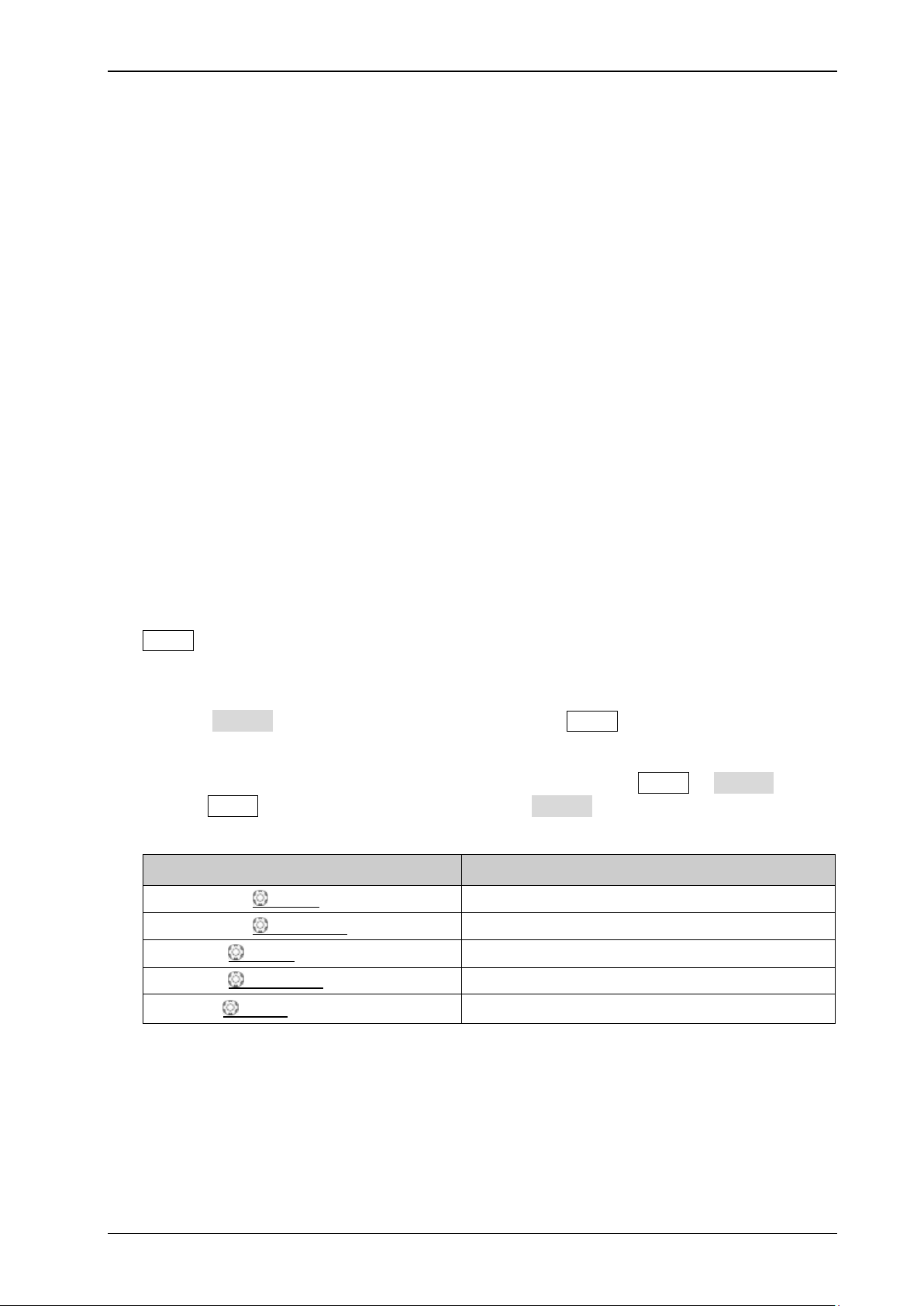
Impedance Test
Specification
Test Connection Di ag ram
Figure 2-1 Impedance Test Connection Diagram
Test Procedures
1. Connect the active head of Fluke 9500B to CH1 of th e osci llos cope , as shown in the figure above.
2. Configure the oscilloscope:
1) Press CH1 in the vertical control area (VERTICAL) on the front panel to turn on CH1.
2) Press CH1 Probe to set the probe attenuation ratio to "1X".
3) Rotate VERTICAL SCALE to set the vertical scale of CH1 to 100 mV/div.
3. Turn on Fluke 9500B; set its impedance to 1 MΩ and select the resistance mea surement f unction .
Read and record the resistance measured.
4. Rotate VERTICAL
mV/div; read and record the resistance measured.
5. Turn off CH1. Measure the resistance of CH2 using the method above and record the
measurement results.
Test Record Form
SCALE to adjust the vertical scale of CH1 of the oscilloscope to 500
CH1
CH2
0.99 MΩ to 1.01 MΩ
DS1000Z-E Performance Verification Guide
Page 15

Chapter 2 Performance Verification Test RIGOL
2-3
DC Gain Accuracy
< 10 mV: ±4% × Full Scale
[1]
≥ 10 mV: ±3% × Full Scale
Fluke 9500B
DS1000Z-E
DC Gain Accuracy Test
Specification
Specification
[1]
Note
: Full Scale = 8 × Current Vertical Scale
[1]
Test Connection Di ag ram
Figure 2-2 DC Gain Accurac y Test Connection Diagram
Test Procedures
1. Connect the active head of Fluke 9500B to CH1 of th e osci llos cope , as shown in the figure above.
2. Turn o n Fluke 9500B and set its impedance to 1 MΩ.
3. Output a DC signal with +3 mV
4. Configure the oscilloscope:
1) Press CH1 in the vertical control area (VERTICAL) on the front panel to turn on CH1.
2) Press CH1 Probe to set the probe attenuation ratio to "1X".
3) Rotate VERTICAL SCALE to set the vertical scale to 1 mV/div.
4) Rotate HORIZONTAL SCALE to set the horizontal time base to 100 us/div.
5) Press VERTICAL POSITION to set the vertical position to 0.
6) Press Acquire Mode and use to select "Average" acquisition mode; press Averages
and use to set the number of averages t o 32.
7) Adjust the trigger level to avoid that the signals are being triggered by mistake.
5. Press MENU Vavg at the left side of the screen of the oscilloscope to turn on the average
measurement function. Read and record Vavg1.
6. Adjust Fluke 9500B to make it output a DC signal with -3 mV
7. Press MENU Vavg at the left side of the screen of the oscilloscope to turn on the average
measurement function. Read and record Vavg2.
8. Calculate the relative error of this vertic al scale: |(Vavg1 - Vavg2) - (Vout1 - Vout2)|/Full
Scale × 100%.
9. Keep the other settings of the oscilloscope unchanged:
1) Set the vertical scale to 2 mV/div, 5 mV/div, 10 mV/div, 20 mV/div, 50 mV/div, 100 mV/div,
voltage (Vout1) via Fluke 9500B.
DC
voltage (Vout2).
DC
DS1000Z-E Performance Verification Guide
Page 16

RIGOL Chapter 2 Performance Verification Test
2-4
Vertical
Test Result
Vavg1
Vavg2
Calculation Result
[1]
1 mV/div
2 mV/div
5 mV/div
10 mV/div
20 mV/div
50 mV/div
100 mV/div
200 mV/div
500 mV/div
1 V/div
2 V/div
5 V/div
10 V/div
1 mV/div
2 mV/div
5 mV/div
10 mV/div
20 mV/div
50 mV/div
100 mV/div
200 mV/div
500 mV/div
1 V/div
2 V/div
5 V/div
10 V/div
200 mV/div, 500 mV/div, 1 V/div, 2 V/div, 5 V/div and 10 V/div respectively.
2) Adjust the output voltage of Fluke 9500B to 3 × the current vertical scale and -3 × the
current vertical scale respectively.
3) Repeat steps 3 to 7 and record the test results.
4) Calculate the relative err or of eac h v erti cal scale: |(Vavg1 - Vavg2) - (Vout1 - Vout2)|/
Full Scale × 100%.
10. Turn off CH1. Test the relative error of each scale of CH2 using the method above and record the
test results.
Test Record Form
Channel
CH1
CH2
Scale
Limit Pass/Fail
≤ 4%
≤ 3%
≤ 4%
≤ 3%
[1]
Note
are 3 × the current vertical scale and -3 × the current vertical scale respectively.
: The calculation formula is |(Vavg1 - Vavg2) - (Vout1 - Vout2)|/Full Scale × 100%; w h er ein , Vout1 and Vout2
DS1000Z-E Performance Verification Guide
Page 17

Chapter 2 Performance Verification Test RIGOL
2-5
Bandwidth
Amplitude Loss
[1]
200 MHz
-3 dB, all-channel mode
Fluke 9500B
DS1000Z-E
50 Ω Impedance Adapter
Bandwidth Test
The bandwidth test verif i es the bandwidth performance of the oscilloscope by testing the amplitude
loss of the oscilloscope under test at full bandwidth.
Specification
[1]
Note
effective value at 1MHz and Vrms2 is the measurement result of amplitude effective value at full bandwidth.
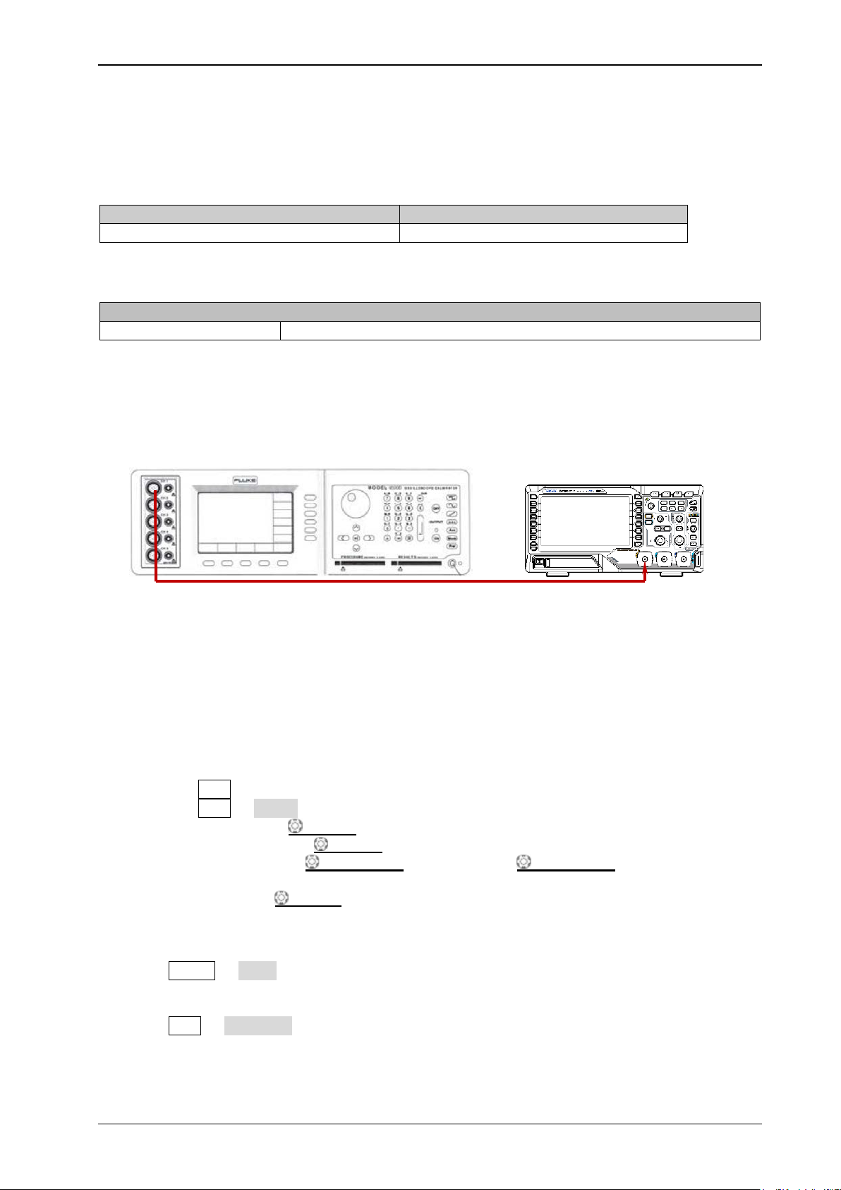
Test Connection Di ag ram
: Amplitude Loss (dB) = 20 × lg (Vrms2/Vrms1); wherein, Vrms1 is the measurement result of amplitude
Figure 2-3 Bandwidth Test Connection Diagram
Test Procedures
1. Connect the active head of Fluke 9500B to CH1 of the oscill osc ope via a 50 Ω impe dan ce a dapte r,
as shown in the figure above.
2. Turn o n Fluke 9500B and set its impedance to 50 Ω.
3. Configure the oscilloscope:
1) Press CH1 in the vertical control area (VERTICAL) on the front panel to turn on CH1.
2) Press CH1 Probe to set the probe attenuation ratio to "1X".
3) Rotate HORIZONTAL SCALE to set the horizontal time base to 500 ns/div.
4) Rotate VERTICAL SCALE to set the vertical scale to 10 0 mV /div.
5) Press HORIZONTAL POSITION and VERTICAL POSITION respectively to set the
horizontal position and vertical position to 0.
6) Press TRIGGER LEVEL to set the trigger level to 0 V.
4. Output a Sine with 1 MHz frequency and 600 mVpp amplitude via Fluke 9500B.
5. Press MENU Vrms at the left side of the screen of the oscilloscope to turn on the effective
value measurement function. Read and record Vrms1.
6. Output a Sine with 200 MHz frequenc y and 600 mVpp amplitude via Fluke 9500B.
7. Rotate HORIZONTAL
8. Press MENU Vrms at the left side of the screen of the oscilloscope to turn on the effective
value measurement function. Read and record Vrms2.
SCALE to set the horizontal time base to 2 ns/div.
DS1000Z-E Performance Verification Guide
Page 18

RIGOL Chapter 2 Performance Verification Test
2-6
Test Result
Amplitude
Loss
100 mV/div
500 mV/div
100 mV/div
500 mV/div
9. Calculate the amplitude loss: Amplitude Loss (dB) = 20 × lg (Vrms2/Vrms1).
10. Keep the other settings of the oscilloscope in Step 3 unchanged and set the vertical scale to 500
mV/div.
11. Output a Sine with 1 MHz frequency and 3 Vpp ampli t ude via Fluke 9500B.
12. Repeat Step 5.
13. Output a Sine with 200 MHz frequency and 3 Vpp amplitude via Fluke 9500B.
14. Repeat Step 7-9.
15. Turn off CH1. T est CH2 using the method above and record the test results.
Test Record Form
Channel
CH1
CH2
[1]
Note
: Amplitude Loss (dB) = 20 × lg (Vrms2/Vrms1).
Vertical
Scale
Vrms1 Vrms2
[1]
Limit Pass/Fail
-3 dB to 3 dB
DS1000Z-E Performance Verification Guide
Page 19
Chapter 2 Performance Verification Test RIGOL
2-7
Input Impedance of the Oscilloscope
Available Bandwidth Limit
1 MΩ
20 MHz
Bandwidth Limit
Amplitude Loss
[1]
-3 dB, all-channel mode
DS1000Z-E
Fluke 9500B
Bandwidth Limit Test
The bandwidth limit test v erifies the 20 MHz bandwidth limit function of the os cilloscope by testin g the
amplitude loss of the oscilloscope under test at the bandwidth limit.
Table 2-2 Bandwidth Limit
Specification
[1]
Note
effective value at 1 MHz; Vrms2 is the measurement result of amplitude effective value at the bandwidth limit.
Test Connection Di ag ram
: Amplitude Loss (dB) = 20 × lg (Vrms2/Vrms1). Wherein, Vrms1 is the measurement result o f ampl itude
Figure 2-4 Bandwidth Limit Test Connection Diagram
Test Procedures
1. Connect the active head of Fluke 9500B to CH1 of the oscilloscope , as shown in the figure above.
2. Turn o n Fluke 9500B and set its impedance to 1 MΩ.
3. Configure the oscilloscope:
1) Press CH1 in the vertical control area (VERTICAL) on the front panel to turn on CH1.
2) Press CH1 Probe to set the probe attenuation ratio to "1X".
3) Rotate VERTICAL SCALE to set the vertical scale to 100 mV/div.
4) Rotate HORIZONTAL SCALE to set the horizontal time base to 500 ns/div.
5) Press HORIZONTAL POSITION and VERTICAL POSITION respectively to set the
horizontal position and vertical position to 0.
6) Press TRIGGER LEVEL to set the trigger level to 0 V.
4. Output a Sine wit h 1 MHz frequency and 600 mVpp amplitude via Fluke 9500B.
5. Press MENU Vrms at the left side of the screen of the oscilloscope to turn on the effective
value measurement function. Read and record Vrms1.
6. Press CH1 BW Limit to set the bandwidth limit to "20 M".
7. Output a Sine with 20 MHz frequency and 600 mVpp amplitude via Fluke 9500B.
DS1000Z-E Performance Verification Guide
Page 20

RIGOL Chapter 2 Performance Verification Test
2-8
Test Result
Amplitude
Loss
100 mV/div
500 mV/div
100 mV/div
500 mV/div
8. Rotate HORIZONTAL SCALE to set the horizontal time base to 50 ns/div.
9. Press MENU Vrms at the left side of the screen of the oscilloscope to turn on the effective
value measurement function. Read and record Vrms2.
10. Calculate the amplitude loss: Amplitude Loss A1 (dB) = 20 × lg (Vrms2/Vrms1) and
compare the result with the specification. At this point, the amplitude loss should be within the
specification range .
11. Keep the other settings of the oscilloscope in Step 3 unchanged and set the vertical scale to 500
mV/div.
12. Output a Sine with 1 MHz frequency and 3 Vpp amplitude via Fluk e 9500B.
13. Repeat Step 5.
14. Output a Sine with 20 MHz frequency and 3 Vpp amplitude via Fluke 9500B.
15. Repeat Step 8-10.
16. Turn off CH1. T est CH2 usi ng the met ho d above.
Test Record Form
Channel
CH1
CH2
[1]
Note
Vertical
Scale
: Amplitude Loss (dB) = 20 × lg (Vrms2/Vrms1).
Vrms1 Vrms2
[1]
Limit Pass/Fail
-3 dB to 3 dB
DS1000Z-E Performance Verification Guide
Page 21

Chapter 2 Performance Verification Test RIGOL
2-9
Time Base Accuracy
[1]
≤ ±(25 ppm + Clock Drift
[2]
×Number of years t hat the instrument h as
been used
Fluke 9500B
DS1000Z-E
Time Base Accura cy Test
Specification
Specification
[1]
Note
Note
Note
verification certificate provided when the instrument leaves factory.
: Typical.
[2]
: Clock drift is lower than or equal to ±5 ppm/year.
[3]
: For the number of years that the instrument has been used, please calculate according to the date in the
[3]
)
Test Connection Diagram
Figure 2-5 Time Base Accurac y Test Connection Diagram
Test Procedures
1. Connect the active head of Fluke 9500B to CH1 of th e osci llos cope , as shown in the figure above.
2. Turn on Fl uke 9500B and set its impedance to 1 MΩ.
3. Output a Sine with 10 MHz frequency and 1.2 Vpp amplitude via Fluke 9500B.
4. Configure the oscilloscope:
1) Press CH1 in the vertical control area (VERTICAL) on the front panel to turn on CH1.
2) Press CH1 Probe to set the probe attenuation ratio to "1X".
3) Rotate VERTICAL SCALE to set the vertical scale to 200 mV/div.
4) Press VERTICAL POSITION to set the vertical position to 0.
5) Rotate HORIZONTAL SCALE to set the horizontal time base to 10 ns/div.
6) Rotate HORIZONTAL POSITION to set the horizontal p osition to 1 ms.
5. Observe the s creen of the o scilloscope . Press Cursor Mode "Manual" to t urn on the manual
cursor function. Measure the offset (ΔT) of the middle point o f t he signal ( namely the crossing
point of the rising edge of t he current signal and the trigger level line ) relative to the screen center
using manual cursor measurement and record the measurement result.
6. Calculate the time b ase ac curacy; na mely the ratio of ΔT to the horizontal position of the
oscilloscope. For example, if the offset measured is 1 ns, the time ba se accuracy is 1 ns/1 ms=1
ppm.
7. Calculate the time b ase accuracy limit using the formula "±(25 ppm + 5 ppm/year × number of
years that the instrument has been used).
DS1000Z-E Performance Verification Guide
Page 22

RIGOL Chapter 2 Performance Verification Test
2-10
Channel
Test Result ΔT
Calculation Result
[1]
Limit
Pass/Fail
±(25 ppm + 5 ppm/year ×
instrument has been used
)
Test Record Form
CH1
[1]
Note
Note
verification certificate provided when the instrument leaves factory.
: Calculation Result = Test Result ΔT/1 ms.
[2]
: For the number of years that the instrument has been used, please calculate according to the date in the
number of years that the
[2]
DS1000Z-E Performance Verification Guide
Page 23
Chapter 2 Performance Verification Test RIGOL
2-11
Zero Point Offset
Specification
2.5 ns
Fluke 9500B
DS1000Z-E
50 Ω Impedance Adapter
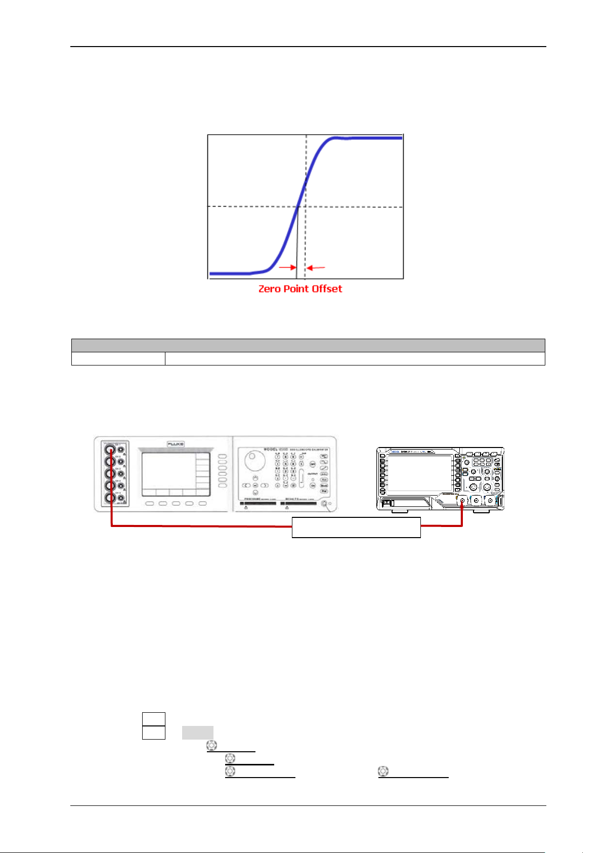
Zero Point Offset Test
Zero point offset is defined as the offset of the crossing point of the waveform and trigger level line
relative to the trigger position, as shown in the figure below.
Specification
Test Connection Diagram
Figure 2-6 Zero Point Offset Test Connection Diagram
Test Procedures
1. Connect the active signal terminal of Fluke 9500B to CH1 of the oscilloscope via a 50 Ω impedance
adapter, as shown in the figure above.
2. Turn o n Fluke 9500B an d se t i ts impedance to 50 Ω.
3. Output a fast edge signal with 500 ps rise time and 1.2 V amplitude via Fluke 9500B.
4. Configure the oscilloscope:
1) Press CH1 in the vertical control area (VERTICAL) on the front panel to turn on CH1.
2) Press CH1 Probe to set the probe attenuation ratio to "1X".
3) Rotate VERTICAL SCALE to set the vertical scale to 20 0 mV/div.
4) Rotate HORIZONTAL SCALE to set the horizontal time base to 5 ns/div.
5) Rotate HORIZONTAL POSITION and VERTICAL POSITION respectively to
DS1000Z-E Performance Verification Guide
Page 24

RIGOL Chapter 2 Performance Verification Test
2-12
Fast Edge Signal
Amplitude
Vertical
Scale
1.2 Vpp
200 mV/div
3 Vpp
500 mV/div
1.2 Vpp
200 mV/div
3 Vpp
500 mV/div
adjust the horizontal position and vertical position properly.
6) Rotate TRIGGER
LEVEL to adjust the trigger level to the middle of the screen.
5. Observe the s creen of the o scilloscope . Press Cursor Mode "Manual" to t urn on the manual
cursor function. Measure the zero point offset using manual cursor measurement and record the
measurement result.
6. Output a fast edge signal with 500 ps rise time and 3 V amplitude via Fluke 9500B.
7. Keep the oth er settings of the oscilloscope unchanged and set the vertical scale to 500 mV/div.
8. Repeat Step 5; measure the zero point offset and record the measurement result.
9. Turn off CH1. Test CH2 according to the method above and record the test results.
Test Record Form
Channel
Test Result Limit
Pass/Fail
CH1
≤ 2.5 ns
CH2
DS1000Z-E Performance Verification Guide
Page 25
Appendix Test Record Form RIGOL
1
Model:
Tested by:
Test Date:
Channel
Vertical Scale
Test Result
Limit
Pass/Fail
Test Result
Calculation
Result
1 mV/div
2 mV/div
5 mV/div
10 mV/div
20 mV/div
50 mV/div
100 mV/div
200 mV/div
500 mV/div
1 V/div
2 V/div
5 V/div
10 V/div
1 mV/div
2 mV/div
5 mV/div
10 mV/div
20 mV/div
50 mV/div
100 mV/div
200 mV/div
500 mV/div
1 V/div
2 V/div
5 V/div
10 V/div
Test Result
Amplitude
Loss
100 mV/div
500 mV/div
100 mV/div
500 mV/div
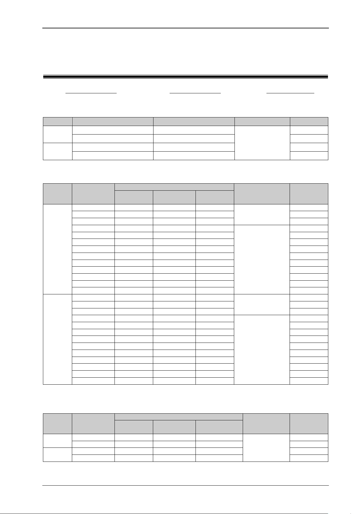
Appendix Test Record Form
RIGOL DS1000Z-E Series Digital Oscilloscope
Performance Verification Test Record Form
Impedance Test
CH1
CH2
100 mV/div
500 mV/div
100 mV/div
500 mV/div
DC Gain Accuracy Test
Channel
CH1
Vertical
Scale
Vavg1 Vavg2
0.99 MΩ to 1.01 MΩ
[1]
Limit Pass/Fail
≤ 4%
≤ 3%
≤ 4%
CH2
[1]
Note
are 3 × the current vertical scale and -3 × the current vertical scale respectively.
: The calculation formula is |(Vavg1 - Vavg2) - (Vout1 - Vout2)|/Full Scale × 100%; wh er ei n , Vout1 and Vout2
Bandwidth Test
Channel
CH1
CH2
[1]
Note
DS1000Z-E Performance Verification Guide
: Amplitude Loss (dB) = 20 × lg (Vrms2/Vrms1).
Vertical
Scale
Vrms1 Vrms2
[1]
≤ 3%
Limit Pass/Fail
-3 dB to 3 dB
Page 26

RIGOL Appendix Test Record Form
2
Test Result
Amplitude
Loss
100 mV/div
500 mV/div
100 mV/div
500 mV/div
Calculation
Result
±(25 ppm + 5 ppm/year × number of years
that the instrument has been used
)
Fast Edge Signal
Amplitude
1.2 Vpp
200 mV/div
3 Vpp
500 mV/div
1.2 Vpp
200 mV/div
3 Vpp
500 mV/div
Bandwidth Limit Test
Channel
Vertical
Scale
Vrms1 Vrms2
CH1
CH2
[1]
Note
: Amplitude Loss (dB) = 20 × lg (Vrms2/Vrms1).
Time Base Accuracy Test
Channel Test Result ΔT
CH1
[1]
Note
Note
verification certificate provided when the instrument leaves factory.
: Calculation Result = Test Result ΔT/1 ms.
[2]
: For the number of years that the instrument has been used, please calculate according to the date in the
[1]
Zero Point Offset Test
Channel
CH1
CH2
Vertical Scale Test Result Limit
[1]
-3 dB to 3 dB
Limit Pass/Fail
[2]
Limit Pass/Fail
≤ 2.5 ns
Pass/Fail
DS1000Z-E Performance Verification Guide
 Loading...