

Page 1

RIGOL
User’s Guide
MSO1000Z/DS1000Z Series
Digital Oscilloscope
Aug. 2015
RIGOL Technologies, Inc.
Page 2

Page 3

RIGOL
Guaranty and Declaration
Copyright
© 2014 RIGOL Technologies, Inc. All Rights Reserved.
Trademark Information
RIGOL is a registered trademark of RIGOL Technologies, Inc.
Publication Number
UGA19108-1110
Software Version
00.04.03.SP1
Software upgrade might change or add product features. Please acquire the latest
version of the manual from RIGOL website or contact RIGOL to upgrade the
software.
Notices
RIGOL products are cove red by P.R.C. and f oreign pa tents, issue d and pendin g.
RIGOL reserves the right to modify or change parts of or all the specifications
and pricing policies at company’s sole decision.
Information in this publica tion re places all previ ously corresponding material.
Information in this publication is subject to change without notice.
RIGOL shall not be liable for either incidental or consequential losses in
connection with the furnishing, use or performance of this manual as well as a ny
information contained.
Any part of this document is forbidden to be copi e d, photocopied or rearranged
without prior written approval of RIGOL.
Product Certification
RIGOL guar antees this pr oduct confo rms to the national and industrial standards in
China as well as the ISO9001:2008 standard and the ISO14001:2004 standard.
Other international standard conformance certif ication is in progress.
Contact Us
If you have any problem or requirement when using our products or this manual,
please contact RIGOL.
E-mail: service@rigol.com
Website: www.rigol.com
MSO1000Z/DS1000Z User’s Guide I
Page 4

RIGOL
Safety Requirement
General Safety Summary
Please review the following safety precautions carefully before putting the
instrument into operation so as to avoid any personal injury or damag e to the
instrument and any product connecte d to it. To prevent potential haza rds, please us e
the instrument only specified by this manual.
Use Proper Power Cord.
Only the power cord designed for the instrument and authorized for use within the
local country could be used.
Ground the Instrument.
The instrument is grounded through the Protective Earth lead of the power cord. To
avoid electric shock, it is e ssential t o connect the ea rth terminal of the power cord to
the Protective Earth terminal before connecting any inputs or outputs.
Connect the Probe Correctly.
If a probe is used, do not connect the ground lead to high vol t age since it has
isobaric electric potential as the ground.
Observe All Terminal Ratings.
To avoid fire or shock hazard, observe all ratin gs and markers on the instrume nt and
check your manual for more information about ratings before connecting the
instrument.
Use Proper Overvoltage Protection.
Make sure that no overvoltage (such as that caused by a thunderstorm) can reach
the product, or else the operator might be exposed to the danger of electrical shock .
Do Not Operate Without Covers.
Do not operate the instrument with covers or panels removed.
Do Not Insert Anything Into the Holes of Fan.
Do not insert anything into the holes of the fan to avoid damaging the instrument.
Use Proper Fuse.
Please use the specified fuses.
Avoid Circuit or Wire Exposure.
Do not touch exposed junctions and components when the unit is powered.
II MSO1000Z/DS1000Z User’s Guide
Page 5

RIGOL
Do Not Operate With Suspected Failures.
If you suspect damage occurs to the instrument, have it inspected by RIGOL
authorized personnel before further oper at io ns. Any maintenance, adjustment or
replacement especially to circuits or accessories must be performed by RIGOL
authorized personnel.
Keep Well Ventilation.
Inadequate ventilation may cause an increase of instrument temperature which
would cause damage to the instrument. So please keep the instrument well
ventilated and inspect the intake and fan regularly.
Do Not Operate in Wet Conditions.
In order to av oid short circuiting t o the interi or of the device or electric shock, please
do not operate the instrument in a humid environment.
Do Not Operate in an Explosive Atmosphere.
In order to avoid damage to the device or personal injuries, it is important to o perate
the device away fr om an expl osive atmosphere.
Keep Product Surfaces Clean and Dry.
To avoid the influence of dust and/or moisture in the air, please keep the surface of
the device clean and dry.
Electrostatic Prevention.
Operate the instrument i n an ele ctrostatic discha rge protectiv e envi ronment to avoid
damage induced by static discharges. Always ground both the internal and external
conductors of cables to release static before making connections.
Proper Use of Battery.
If a battery is supplied, it must not be exposed to high temperature or in contact with
fire. Keep it out of the reach of children. Improper change of battery (note: lithium
battery) may cause explosion. Use RIGOL specified battery on l y.
Handling Safety.
Please handle with care during transportation to avoid damage to keys, knob
interfaces and other parts on the panels.
MSO1000Z/DS1000Z User’s Guide III
Page 6
RIGOL
WARNING
injury or loss of life.
CAUTION
damage to this product or other property.
DANGER
It calls attention to an operation, if not correctly pe rformed, could
result in injury or hazard immediately.
WARNING
It calls attention to an operation, if not correctly pe rformed, could
result in potential injury or hazard.
CAUTION
It calls attention to an operation, if not correctly pe rformed, could
product.
Hazardous
Safety
Protective
Chassis
Test
Safety Terms and Symbols
Terms Used in this Manual. These terms may appear in this manual:
Warning statements indicate conditions or practices that could result in
Caution statements indicate conditions or practices that could result in
Terms Used on the Product. These terms may appear on the product:
result in damage to the product or other devices connected to the
Symbols Used on the Product. These symbols may appear on the product:
Voltage
Warning
Earth
Terminal
Ground
Ground
IV MSO1000Z/DS1000Z User’s Guide
Page 7

RIGOL
Allgemeine Sicherheits Informationen
Überprüfen Sie diefolgenden Sicherheitshinweise
sorgfältigumPersonenschädenoderSchäden am Gerätundan damit verbundenen
weiteren Gerätenzu vermeiden. Zur Vermeidung vonGefahren, nut zen Sie bitte das
Gerät nur so, wiein diesem Handbuchangegeben.
Um Feuer oder Verletzungen zu vermeiden, verwenden Sie ein
ordnungsgemäßes Netzkabel.
Verwenden Sie für dieses Gerät nur das für ihr Land zugelassene und genehmigte
Netzkabel.
Erden des Gerätes.
Das Gerät ist durch den Schutzleiter im Netzkabel geerdet. Um Gefahren durch
elektrischen Schlag zu vermeiden , ist es unerlässlich, die Er dung durchzufüh ren. Erst
dann dürfen weitere Ein- oder Ausgänge verbunden werden.
Anschluss einesTastkopfes.
Die Erdungsklemmen der Sonden sindauf dem gleichen Spannungspegel des
Instruments geerdet. SchließenSie die Erdungsklemmen an keine hohe Spannung
an.
Beachten Sie alle Anschlüsse.
Zur Vermeidung von Feuer oder Stromschlag, beachten Sie alle Bemerkungen und
Markierungen auf dem Instrument. Bef olgen Sie die Bedienun gsanleitung für weitere
Informationen, bevor Sie weitere Anschlüsse an das Instrument legen.
Verwenden Sie einen geeigneten Überspannungsschutz.
Stellen Sie sicher, daß keinerlei Überspannung (wie z.B. durch Gewitter verursacht)
das Gerät erreichen kann. Andernfallsbestehtfür den Anwender die
GefahreinesStromschlages.
Nicht ohne Abdeckung einschalten.
Betreiben Sie das Gerät nicht mit entfernten Gehäuse-Abdeckungen.
Betreiben Sie das Gerät nicht geöffnet.
Der Betrieb mit offenen oder entfernten Gehäuseteilen ist nicht zulässig. Nichts in
entsprechende Öffnungen stecken (Lüfter z.B.)
Passende Sicherung verwenden.
Setzen Sie nur die spezifikationsgemäßen Sicherungen ein.
Vermeiden Sie ungeschützte Verbindungen.
Berühren Sie keine unisolierten Verbindungen oder Baugruppen, während das Gerät
in Betrieb ist.
MSO1000Z/DS1000Z User’s Guide V
Page 8

RIGOL
Betreiben Sie das Gerät nic h t i m Fehlerfall.
Wenn Sie am Gerät einen Defekt vermuten, sorgen Sie dafür, bevor Sie das Gerät
wieder betreiben, dass eine Untersuchung durch RIGOL autorisiertem Personal
durchgeführt wird. Jedwede W artun g, Einstellarbeit en oder Austausch v on Teilen am
Gerät, sowie am Zubehör dürfen nur von RIGOL autorisiertem Pe rs onal
durchgeführt werden.
Belüftung sicherstellen.
Unzureichende Belüftung kann zu Temperaturanstiegen und somit zu thermischen
Schäden am Gerät führen. Stellen Sie deswegen die Belüftung sicher und
kontrollieren regelmäßig Lüfter und Belüftungsöffnungen.
Nicht in feuc h te r Um g ebung betrei be n .
Zur Vermeidun g von Kurzschluß im Geräteinne ren und Stromschlag betreiben Sie das
Gerät bitte niemals in feuchter Umgebung.
Nicht in explosiver Atmosphäre betreiben.
Zur Ve rm e idung von Pe rsonen- und Sachschäden ist es unumgänglich, das Gerät
ausschließlich fernab jedweder explosiven At mosphäre zu betreiben.
Geräteoberflächen sauber und trocken halten.
Um den Einfluß von Staub und Feuchtigkeit aus der Luft auszuschließen, halten Sie
bitte die Geräteoberflächen sauber und trocken.
Schutz gegen elektrostatische Entladung (ESD).
Sorgen Sie für eine elektrostatisch geschützte Umgebung, um somit Schäden und
Funktionsstörungen durch ESD zu vermeiden. Erden Sie vor dem Anschluß immer
Innen- und Außenleiter der V erbindungsleitung, um sta tische Aufladung zu entladen.
Die richtige Verwendung desAkku.
Wenneine Batterieverwendet wird, vermeiden Sie hohe Temperaturen bzw. Feuer
ausgesetzt werden. Bewahren Sie es außerhalbder Reichweitevon Kindern auf.
Unsachgemäße Änderung derBatt e rie (Anmerkung: Lithium-Batterie) kann zu einer
Explosion führen. VerwendenSie nur von RIGOL angegebenenAkkus.
Sicherer Transport.
Transportieren Sie das Gerät sorgfältig (Verpackung!), um Schäden an
Bedienelementen, Anschlüssen und anderen Teilen zu vermeiden.
VI MSO1000Z/DS1000Z User’s Guide
Page 9
RIGOL
WARNING
Schäden oder den Tod von Personen zur Folge haben können.
CAUTION
Schäden am Gerät hervorrufen können.
DANGER
weist auf eine Verletzung ode r Gefäh r dun g hin, die s o fort
geschehen kann.
WARNING
weist auf eine Verletzung oder Gefäh rdung hin, die möglicherweise
nicht sofort geschehen.
CAUTION
weist auf eine Verletzun g ode r Gefährdung hin und bedeutet, dass
Gegenstände auftreten kann.
Sicherheits Begriffe und Symbole
Begriffe in diesem Guide. Diese Begrif fe können in diesem Handbuch aufta uchen:
Die Kennzeichnung WARNING beschreibt Gefahrenquelle n die leibliche
Die Kennzeichnung Caution (Vorsicht) beschreibt Gefahrenquellen die
Begriffe auf dem Produkt. Diese Bedingungen können auf dem Produkt
erscheinen:
eine mögliche Beschädigung des Instruments oder anderer
Symbole auf dem Produkt. Diese Symbole können auf dem Produkt erscheinen:
Gefährliche
Spannung
SicherheitsHinweis
Schutz-erde Gehäusemasse Erde
MSO1000Z/DS1000Z User’s Guide VII
Page 10

RIGOL
WARNING
measurement categories.
Measurement Category
Measurement Category
MSO1000Z/DS1000Z series digital oscilloscopes can mak e meas urements in
Measurement Category I.
This oscilloscope can only be used for measurements within its specified
Measurement Category Definitions
Measuremen t c ategory I is for measurements performed on circuits not directly
connected to MAINS. Examples a re m e a s urements on circu its not derived from
MAINS, and specially protected (internal) MAINS derived circuits. In the latter case,
transient stresses are variable. For that reason, the transient withstand capability of
the equipment is made known to the user.
Measurement category II is for measurements performed on circuits directly
connected to low voltage installations. Examples are measurements on household
appliances , portable tools and similar equipment.
Measurement category III is for measurements performed in building installations.
Examples are measurements on distribution boards, circuit-breakers, wiring
(including cables, bus-bars, junction boxes, switches and socket-outlets) i n fix ed
installations, equipment for industrial use and some othe r equip ment. For exam ple,
stationary motors with permanent connection to a fixed installation.
Measurement category IV is for measurements performed at the source of a
low-voltage installation. Examples are electricity meters and measurements on
primary overcurrent protection devices and ripple control units.
VIII MSO1000Z/DS1000Z User’s Guide
Page 11

RIGOL
WARNING
during operation and inspect the intake and fan regularly.
Ventilation Requirement
This oscilloscope uses fan to force cooling. Please make sure that the air intake and
exhaust areas are free from obstructions and have free air. When using the
oscilloscope in a bench-top or rack setting, provide at least 10 cm clearance beside,
above and behind the instrument for adequate ventilation.
Inadequate ventilation may cause a temperature increase which can
damage the instrument. So please keep the instrument well ventilated
MSO1000Z/DS1000Z User’s Guide IX
Page 12
RIGOL
WARNING
not operate in humid environment.
WARNING
exposed to the danger of electric shock.
Working Environment
Temperature
Operating: 0℃ to +50℃
Non-operating: -40℃ to +70℃
Humidity
0℃ to +30℃: ≤95% relative humidity
+30℃ to +40℃: ≤75% relative humidity
+40℃ to +50℃: ≤45% relative humidity
To avoid short circuits inside the instrument or electric shocks, please do
Altitude
Operating: below 3 km
Non-operating: below 15 km
Installation (Overvoltage) Category
This product is powered by mains conforming to installation (overvoltage) category
II.
Installation (Overvoltage) Cate g o ry Definitio n s
Installation (overvoltage) category I refers to signal level which is applicable to
equipment measurement terminals connected to the source circuit. In these
terminals, precautions are done to limit the transient voltage to the corresponding
low level.
Installation (overvoltage) category II refers to the local power distribution level
which is applicable to equipment connected to the AC line (AC power).
Pollution Degree
Degree 2
Pollution Degree Definitions
Pollution degree 1: No pollution or only dry, non-conductive pollution occurs. The
pollution has no influence. For example, a clean room or air-conditioned office
environment.
X MSO1000Z/DS1000Z User’s Guide
Make sure that no over volta ge (such as that produced by a
thunderstorm) can reach the product, or else the operator might be
Page 13

RIGOL
Pollution degree 2: Normally only dry, non-conductive pollution occurs. Occasionally
a temporary conductivity caused by condensation may occur. For example, general
indoor environment.
Pollution degree 3: Conductive pollution occurs, or dry, non-conductive pollution
occurs which becomes conductive due to condensation which is expected. For
example, sheltered outdoor environment.
Pollution degree 4: Pollution that generates persistent conductivity through
conductive dust, rain, or snow. For ex amp le, outdoor locations.
Safety Class
Class 1 – Grounded Product
MSO1000Z/DS1000Z User’s Guide XI
Page 14
RIGOL
CAUTION
WARNING
supply.
General Care and Cleaning
General Care
Do not store or leave the instrument where it may be exposed to direct sunlight for
long periods of time.
Cleaning
Clean the instrument regularly according to its operating conditions. To clean the
exterior surface, perform the following steps:
1. Disconnect the instrument from all power sources.
2. Clean the loose dust on th e outs ide of the inst rumen t with a lint-free cloth (with
a mild detergent or water). When cleaning the LCD, take care to av oid scari fying
it.
To avoid damage to the instrument, do not expose it to caustic liquids.
To avoid short-circuit and personal injury resulting from moisture, make
sure the instrument is completely dry before reconnecting it to power
Environmental Consideratio ns
The following symbol indicates that this product complies with the WEEE Directive
2002/96/EC.
Product End-of-Life Handling
The equipment may c ontain s ubstan ces that could b e ha rmful t o the envi ronm ent o r
human health. In order to avoid release of such su bstances into the en vironment and
harm to human health, we encourage you to recycle this product in an appropriate
system that will ensure that most of the materials are reused or recycled
appropriately. Please contact your local authorities for disposal or recycling
information.
XII MSO1000Z/DS1000Z User’s Guide
Page 15
RIGOL
MSO1000Z/DS1000Z User’s Guide XIII
Page 16

RIGOL
MSO1000Z/DS1000Z Series Overview
MSO1000Z/DS1000Z series is a multifunctional and high-performance digital
oscilloscope designed on t he basis of t he Ultra Vision t echnique developed by RIGOL.
Featuring extremely high memo ry depth, wide dyn amic range, clear display,
excellent waveform capture rate and comprehensive triggering functions, it is a
useful commissioning instrument for various fields such as communication,
aerospace, defense, embedded systems, computers, research and education.
Wherein, the mixed signal digital oscilloscope aimed at the embedded design and
test field s allows users to measure analog and digital signals at the same time.
MSO1000Z/DS1000Z is the one with the most comprehensive functio ns and the most
outstanding specifications among the 100 MHz bandwidth digital oscilloscopes.
Main feature s:
1 GSa/s real-time sample rate of the analog channels; up to 24 Mpts memory
depth (optional) and 12 Mpts standard memory depth
1 GSa/s real-time sample rate of the digital channels
100 MHz, 70 MHz and 50 MHz analog channel bandwidth
4 analog channels, 16 digital channels (for MSO1000Z and MSO upgradable for
DS1000Z Plus)
Dual-channel 25 MHz signal source (applicable to digital oscilloscopes with
source channels)
30 000 wfms/s (dots display) waveform capture rate
Real-time hardware waveform recording and playback functions; up to 60 000
frames of waveform can be recorded
MSO field upgradable with MSO1000Z upgrade package (MSO upgrade option,
only for DS1000Z Plus)
Intensity graded color display
Low base noise, 1 mV/div to 10 V/div ultra-wide vertical dynamic range
7.0 inch WVGA (800*480) TFT LCD, with ultra-wide screen , vivid picture, low
power consumption and long service life
Adjustable waveform brig htne ss
Auto setting of waveform display (AUTO)
Up to 15 kinds of trigger functions, including various protocol triggers
Standard parallel decoding, supports multiple serial decoding options
Auto measurement of 33 waveform parameters (with statistics)
Fine delayed sweep function
Built-in FFT function
Multiple waveform math operation functions
Pass/fail test function
Standard interfaces: USB Device, U S B Host, LAN, Aux, GPIB (extend ed via the
USB Host interface)
Conform to LXI CORE 2011 DEVICE class instrument standards; enable quick,
economic and efficient creation and reconfiguration of test system
Supports remote command control
XIV MSO1000Z/DS1000Z User’s Guide
Page 17

RIGOL
Built-in help to facilitate information acquisition
Supports multiple languages and Chinese/English input
Novel and delicate industrial design and easy operation
MSO1000Z/DS1000Z User’s Guide XV
Page 18

RIGOL
Document Overview
Main Topics of this Manual:
Chapter 1 Quick Start
Introduce the preparations before using the oscilloscope and provide a basic
introduction of the instrument.
Chapter 2 To Set the Vertical System
Introduce the vertical system functions of the oscilloscope.
Chapter 3 To Set the Horizontal System
Introduce the horizontal system functions of the oscilloscope.
Chapter 4 To Set the Sample System
Introduce the sample system functions of the oscilloscope.
Chapter 5 To Trigger the Oscilloscope
Introduce the trigger mode, trigger coupling, trigger holdoff, external trigger and
various trigger types of the oscilloscope.
Chapter 6 MATH and Measurement
Introduce how to make math operation, auto measurement and cursor
measurement.
Chapter 7 Digital Chann e l
Introduce how to use the digital channels of the mixed signal digital oscilloscope.
Chapter 8 Protocol Decoding
Introduce how to decode the input signal using those common protocols.
Chapter 9 Reference Waveform
Introduce how to compare the input waveform with the reference wav ef o rm.
Chapter 10 Pass/Fail Test
Introduce how to monitor the input signal using the Pass/Fail test.
Chapter 11 Waveform Record
Introduce how to analyze the input signal using w aveform re cord.
Chapter 12 Display Control
Introduce how to control the display of the oscilloscope.
Chapter 13 Signal Source
Introduce how to use the built-in signal source.
XVI MSO1000Z/DS1000Z User’s Guide
Page 19
RIGOL
Chapter 14 Store and Recall
Introduce how to store and recall the measurement result and the setting of the
oscilloscope.
Chapter 15 Accessibility Setting
Introduce how to set the remote interfaces and system-related functions.
Chapter 16 Remote Control
Introduce how to control the oscilloscope remotely.
Chapter 17 Troubleshooting
Introduce how to deal with the common failures of the oscilloscope.
Chapter 18 Specifications
Provide the specifications and general specifications of the oscilloscope.
Chapter 19 Appendix
Provide common information such as the options and accessories.
Format Conventions in this Manual:
1. Key
The front panel keys are denoted by the f ormat of "Key Name (Bold) + T ext Box".
For example, Utility denotes the "Utility" key.
2. Menu
The menu items are denoted by the format of "Menu Word (Bold) + Character
Shading". For example, System denotes the "System" menu item under
Utility.
3. Operation Step
The next step of ope ration is denote d b y an a rrow "". For example, Utility
System denotes pressing Utility at the front panel and then pressi ng System.
4. Knob
Label Knob
HORIZONTAL SCALE
HORIZONTAL POSITION
VERTICAL SCALE
VERTICAL POSITION
TRIGGER LEVEL
Horizontal Scale Knob
Horizontal Position Knob
Vertical Scale Knob
Vertical Position Knob
Trigger Level Knob
MSO1000Z/DS1000Z User’s Guide XVII
Page 20
RIGOL
Number of
Channels
Number of
Channels
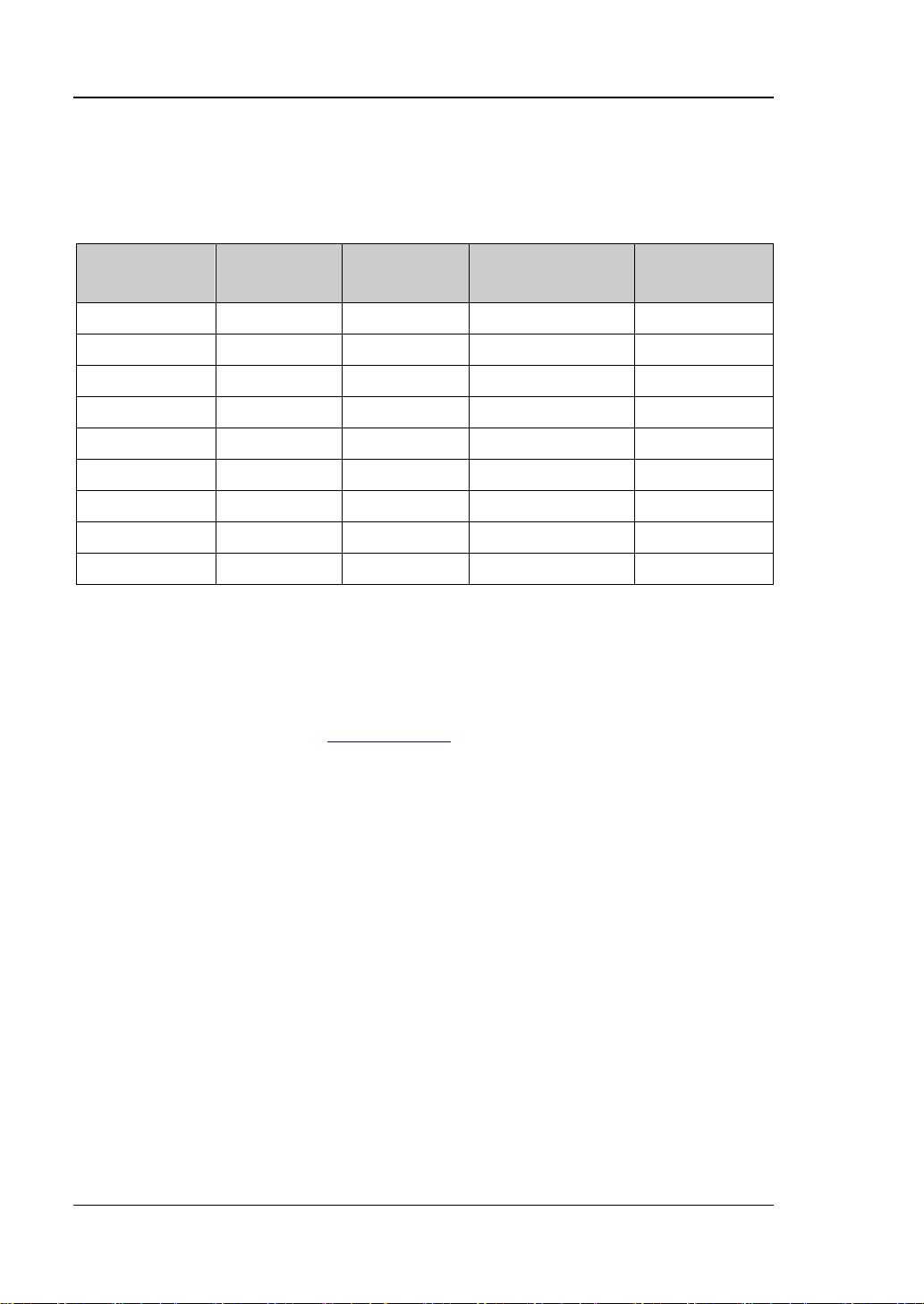
Content Conventions in this Manual:
MSO1000Z/DS1000Z series includes the following models. Unless otherwise noted,
this manual takes MSO1104Z-S for example to illustrate the functions and operation
methods of MSO1000Z/DS1000Z series.
Model
MSO1104Z-S 100 MHz 4 2 16
MSO1074Z-S 70 MHz 4 2 16
MSO1104Z 100 MHz 4 -- 16
MSO1074Z 70 MHz 4 -- 16
DS1104Z-S Plus 100 MHz 4 2 16
DS1074Z-S Plus 70 MHz 4 2 16
DS1104Z Plus 100 MHz 4 -- 16
DS1074Z Plus 70 MHz 4 -- 16
DS1054Z 50 MHz 4 -- --
[1]
Note
: Need to be upgraded to MSO using the MSO upgrade option.
Analog
Bandwidth
Analog
Number of Source
Channels
Digital
[1]
[1]
[1]
[1]
Manuals of this Product:
The manuals of this product include the quick guide, user’s guide, programming
guide, data sheet and etc. The latest versions of the manuals can be downloaded
from RIGOL official website (
www.rigol.com).
XVIII MSO1000Z/DS1000Z User’s Guide
Page 21

Contents RIGOL
Contents
Guaranty and Declaration ......................................................................... I
Safety Requirement ................................................................................ II
General Safety Summary ........................................................................... II
Safety Terms and Symbols ....................................................................... IV
Allgemeine Sicherheits Informationen ......................................................... V
Sicherheits Begriffe und Symbole ............................................................. VII
Measurement Category .......................................................................... VIII
Ventilation Requirement ........................................................................... IX
Working Enviro nment ............................................................................... X
General Care and Cleaning ...................................................................... XII
Environmental Considerations .................................................................. XII
MSO1000Z/DS1000Z Series Overview ................................................. XIV
Document Overview ............................................................................. XVI
Chapter 1 Qui ck Start ......................................................................... 1-1
General Inspection ................................................................................ 1-2
Appearance and Dim e nsions ................................................................... 1-3
To Prepare the Oscilloscope for Use ......................................................... 1-4
To Adjust the Supporting Legs .......................................................... 1-4
To Connect to Power Supply............................................................. 1-4
Power-on Inspection ....................................................................... 1-5
To Connect the Probe ...................................................................... 1-5
Function Inspection ......................................................................... 1-7
Probe Compensation ....................................................................... 1-8
Panel Overview ............................................................................. 1-9
Front
Rear Panel Overview ............................................................................. 1-10
Front Panel Function Overview............................................................... 1-12
VERTICAL ..................................................................................... 1-12
Logic Analyzer ............................................................................... 1-13
Signal Source ................................................................................ 1-13
HORIZONTAL ................................................................................ 1-14
TRIGGER ...................................................................................... 1-15
CLEAR .......................................................................................... 1-15
AUTO............................................................................................ 1-15
RUN/STOP .................................................................................... 1-16
SINGLE ......................................................................................... 1-16
Multifunction Knob ......................................................................... 1-16
Function Menus ............................................................................. 1-17
Print ............................................................................................. 1-18
User Interface ...................................................................................... 1-19
Parameter Setting Method ..................................................................... 1-24
To Use the Security Lock ....................................................................... 1-25
MSO1000Z/DS1000Z User’s Guide XIX
Page 22

RIGOL Contents
To Use the Built-in Help System ............................................................. 1-26
Chapter 2 To Set the Vertical System ................................................. 2-1
To Enable the Analog Channel ................................................................. 2-2
Channel Coupling ................................................................................... 2-2
Bandwidth Limit ..................................................................................... 2-3
Probe Ratio ........................................................................................... 2-3
Waveform Invert .................................................................................... 2-4
Vertical Scale ......................................................................................... 2-4
Amplitude Unit ....................................................................................... 2-5
Channel Label ........................................................................................ 2-5
Delay Calibration of the Analog Channel ................................................... 2-7
Chapter 3 To Set the Horizontal System ............................................ 3-1
Delayed Sweep ...................................................................................... 3-2
Time Base Mode .................................................................................... 3-3
YT Mode ......................................................................................... 3-3
XY Mode ......................................................................................... 3-3
Roll Mode ....................................................................................... 3-5
Chapter 4 To Set the Sample System ................................................. 4-1
Acquisition Mode .................................................................................... 4-2
Normal ........................................................................................... 4-2
Peak Detect .................................................................................... 4-2
Average .......................................................................................... 4-2
High Resolution ............................................................................... 4-3
Sin(x)/x ................................................................................................. 4-4
Sample Rate .......................................................................................... 4-4
Memory Depth ....................................................................................... 4-6
Antialiasing ............................................................................................ 4-7
Chapter 5 To Trigger the Oscilloscope ................................................ 5-1
Trigger Source ....................................................................................... 5-2
Trigger Mode ......................................................................................... 5-3
Trigger Coupling..................................................................................... 5-4
Trigger Holdoff ....................................................................................... 5-5
Noise Rejection ...................................................................................... 5-5
Trigger Type .......................................................................................... 5-6
Edge Trigger ................................................................................... 5-7
Pulse Trigger ................................................................................... 5-8
Slope Trigger ................................................................................. 5-10
Video Trigger................................................................................. 5-13
Pattern Tr igg er .............................................................................. 5-15
Duration Trigger ............................................................................ 5-17
TimeOut Trigger (Optional) ............................................................. 5-19
Runt Trigger (Optional) .................................................................. 5-21
Window Trigger (Optional) .............................................................. 5-23
Delay Trigger (Optional) ................................................................. 5-25
XX MSO1000Z/DS1000Z User’s Guide
Page 23

Contents RIGOL
Setup/Hold Trigger (Optional) ......................................................... 5-28
Nth Edge Trigger (Optional) ............................................................ 5-30
RS232 Trigger (Optional) ................................................................ 5-32
I2C Trigger (Optional) .................................................................... 5-34
SPI Trigger (Optional) .................................................................... 5-37
Trigger Output Connector ...................................................................... 5-39
Chapter 6 MATH and Measurement .................................................... 6-1
Math Operation ..................................................................................... 6-2
Addition ......................................................................................... 6-2
Subtraction .................................................................................... 6-3
Multiplication .................................................................................. 6-4
Division .......................................................................................... 6-4
FFT ............................................................................................... 6-6
"AND" Operation ............................................................................ 6-11
"OR" Operation .............................................................................. 6-12
"XOR" Operation ............................................................................ 6-13
"NOT" Operation ............................................................................ 6-14
Intg .............................................................................................. 6-15
Diff ............................................................................................... 6-16
Sqrt .............................................................................................. 6-17
Lg (Use 10 as the Base) ................................................................. 6-17
Ln ................................................................................................ 6-18
Exp .............................................................................................. 6-19
Abs .............................................................................................. 6-20
Filter............................................................................................. 6-21
Fx Operation ................................................................................. 6-22
Math Operation Label ..................................................................... 6-23
Auto Measurement ............................................................................... 6-24
Quick Measurement after AUTO....................................................... 6-24
One-key Measurement of 33 Parameters .......................................... 6-25
Frequency Counter Measurement .................................................... 6-30
Measuremen t Setting ..................................................................... 6-30
To Clear the Measurement .............................................................. 6-31
All Measurement ............................................................................ 6-33
Statistic Function ........................................................................... 6-33
Measurement History ..................................................................... 6-34
Measurement Result Display Type .................................................... 6-34
Cursor Measurement............................................................................. 6-35
Manual Mode ................................................................................. 6-35
Track Mode ................................................................................... 6-39
Auto Mode .................................................................................... 6-41
XY Mode ....................................................................................... 6-42
Chapter 7 Digital Channel ................................................................... 7-1
To Select the Digital Channel .................................................................. 7-2
To Turn on/off the Digital Channel ........................................................... 7-2
MSO1000Z/DS1000Z User’s Guide XXI
Page 24

RIGOL Contents
Group Set .............................................................................................. 7-3
To Set the Waveform Display Size ............................................................ 7-4
Reorder Setting ...................................................................................... 7-4
Auto View.............................................................................................. 7-4
To Set the Threshold .............................................................................. 7-4
To Set the Label ..................................................................................... 7-5
Probe Calibration .................................................................................... 7-5
Digital Channel Delay Calibration ............................................................. 7-5
Chapter 8 Protocol Decoding ............................................................. 8-1
Parallel Decoding ................................................................................... 8-2
RS232 Decodi n g (Optional) ..................................................................... 8-7
I2C Decoding (Optional) ....................................................................... 8-12
SPI Decoding (Optional) ....................................................................... 8-15
Chapter 9 Reference Waveform ......................................................... 9-1
To Enable REF Function .......................................................................... 9-2
To Select REF Source .............................................................................. 9-2
To Adjust REF Waveform Display ............................................................. 9-2
To Save to Internal Memory .................................................................... 9-2
To Set the Color ..................................................................................... 9-3
To Reset the Reference Waveform ........................................................... 9-3
To Export to Internal or Ext e rn al Memory ................................................. 9-3
To Import from Internal or External Memor y ............................................. 9-3
Chapter 10 Pass/Fail T est ............................................................ 10-1
To Enable Pass/Fail Test ........................................................................ 10-2
To Select Source .................................................................................. 10-2
Mask Range ......................................................................................... 10-2
Test and Output ................................................................................... 10-3
To Save the Test Mask .......................................................................... 10-4
To Load the Test Mask .......................................................................... 10-4
Chapter 11 Waveform Record ...................................................... 11-1
Common Settings ................................................................................. 11-2
Playback Option ................................................................................... 11-3
Record Option ...................................................................................... 11-4
Chapter 12 Display Control .......................................................... 12-1
To Select the Display Type .................................................................... 12-2
To Set the Persistence Time .................................................................. 12-2
To Set the Waveform Intensity .............................................................. 12-3
To Set the Screen Grid .......................................................................... 12-3
To Set the Grid Brightness..................................................................... 12-3
Chapter 13 Signal Source ............................................................ 13-1
To Output Basic Waveform .................................................................... 13-2
To Output Sine .............................................................................. 13-2
To Output Square .......................................................................... 13-3
XXII MSO1000Z/DS1000Z User’s Guide
Page 25

Contents RIGOL
To Output Ramp ............................................................................ 13-4
To Output Pulse ............................................................................. 13-5
To Output DC ................................................................................ 13-5
To Output Noise ............................................................................. 13-6
To Output Built-in Waveform .................................................................. 13-6
To Output Arbitrary Waveform ............................................................. 13-10
To Select Waveform ..................................................................... 13-11
To Create Waveform ..................................................................... 13-12
To Edit Waveform ........................................................................ 13-14
Modulation ........................................................................................ 13-15
AM ............................................................................................. 13-16
FM ............................................................................................. 13-17
Chapter 14 Store and Re call ......................................................... 14-1
Storage System .................................................................................... 14-2
Storage Type ....................................................................................... 14-2
Internal Storage and Recall ................................................................... 14-4
External Storage and Recall ................................................................... 14-5
Disk Management ................................................................................. 14-6
To Select File Type ......................................................................... 14-6
To Create a New File or Folder ........................................................ 14-7
To Delete a File or Folder .............................................................. 14-10
To Rename a File or Folder ........................................................... 14-10
To Clear the Local Memory ............................................................ 14-10
Factory .............................................................................................. 14-11
Chapter 15 Accessibil i ty Setting ................................................... 15-1
Remote Interface Configuration ............................................................. 15-2
LAN Configuration .......................................................................... 15-3
USB Device ................................................................................... 15-6
GPIB Address ................................................................................ 15-6
System-related ..................................................................................... 15-7
Sound ........................................................................................... 15-7
Language ...................................................................................... 15-7
System Informat i on ........................................................................ 15-7
Vertical Reference .......................................................................... 15-7
Power-off Recall ............................................................................. 15-8
Self-calibration ............................................................................... 15-8
Print Setting .................................................................................. 15-9
Aux Output ................................................................................. 15-11
Option Management ..................................................................... 15-12
Auto Options ............................................................................... 15-13
Key Lock ..................................................................................... 15-13
Chapter 16 Remote Control .......................................................... 16-1
Remote Control via USB ........................................................................ 16-2
Remote Control via LAN ........................................................................ 16-6
MSO1000Z/DS1000Z User’s Guide XXIII
Page 26

RIGOL Contents
Remote Control via GPIB ....................................................................... 16-7
Chapter 17 Troubleshooting ........................................................ 17-1
Chapter 18 Specifications ............................................................ 18-1
Chapter 19 Appendix ................................................................... 19-1
Appendix A: Accessories and Options ..................................................... 19-1
Append i x B: Warranty ........................................................................... 19-2
Index ........................................................................................................ 1
XXIV MSO1000Z/DS1000Z User’s Guide
Page 27

Chapter 1 Quick Start RIGOL
Chapter 1 Quick Start
This chapter introduces the preca utions when using t he oscilloscope for the first time,
the front/rear panels of th e os cillosc ope , the user interface and the using method of
the built-in help system.
The contents of this chapter:
General Inspection
Appearance and Dimensions
To Prepare the Oscilloscope for Use
Front
Rear Panel Overview
Front Panel Function Overview
User Interface
Parameter Setting Method
To Use the Security Lock
To Use the Built-in Help System
Panel Overview
MSO1000Z/DS1000Z User’s Guide 1-1
Page 28

RIGOL Chapter 1 Quick Start
General Inspection
1. Inspect the shipping container for damage
Keep the damaged shipping container or cushioning material until the contents
of the shipment have been checked for completeness and the instrument has
passed both ele ctrica l a nd mechanical tests.
The consigner or carrier shall be liable for the damage to instrument resulting
from shipment. RIGOL woul d n ot be responsible f or free maintenance/rework
or replacement of the unit.
2. Inspect the instrument
In case of any damage, or defect, or failure, notify your RIGOL sales
representative.
3. Check the accessories
Please check the accessories according to the packi ng l is t s. If t he accessories
are incomplete or damaged, pleas e contact your RIGOL sales representative.
1-2 MSO1000Z/DS1000Z User’s Guide
Page 29
Chapter 1 Quick Start RIGOL
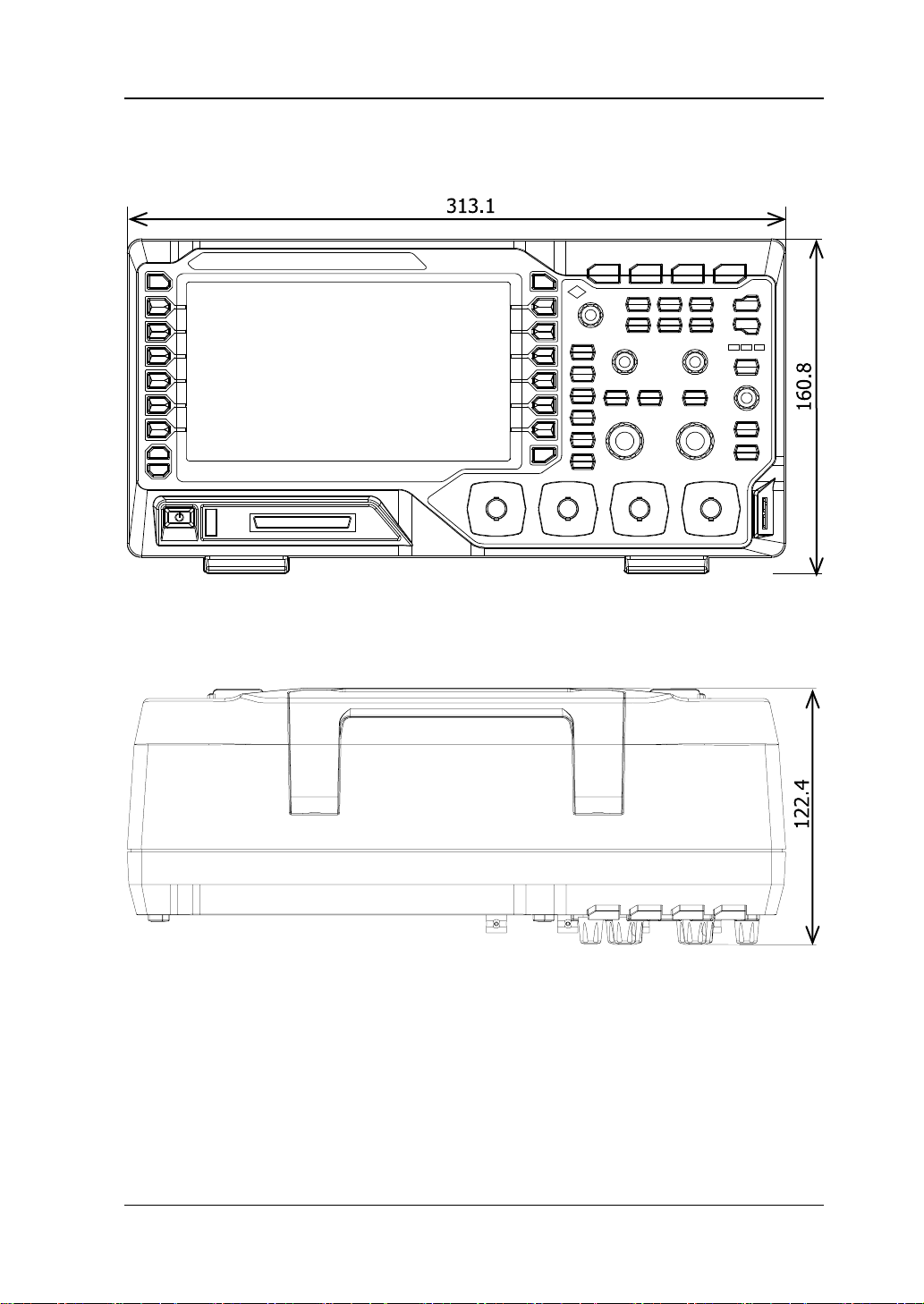
Appearance and Dimensions
Figure 1-1 Front View Unit: mm
Figure 1-2 Top View Unit: mm
MSO1000Z/DS1000Z User’s Guide 1-3
Page 30
RIGOL Chapter 1 Quick Start
Power Socket
To Prepare the Oscilloscope for Use
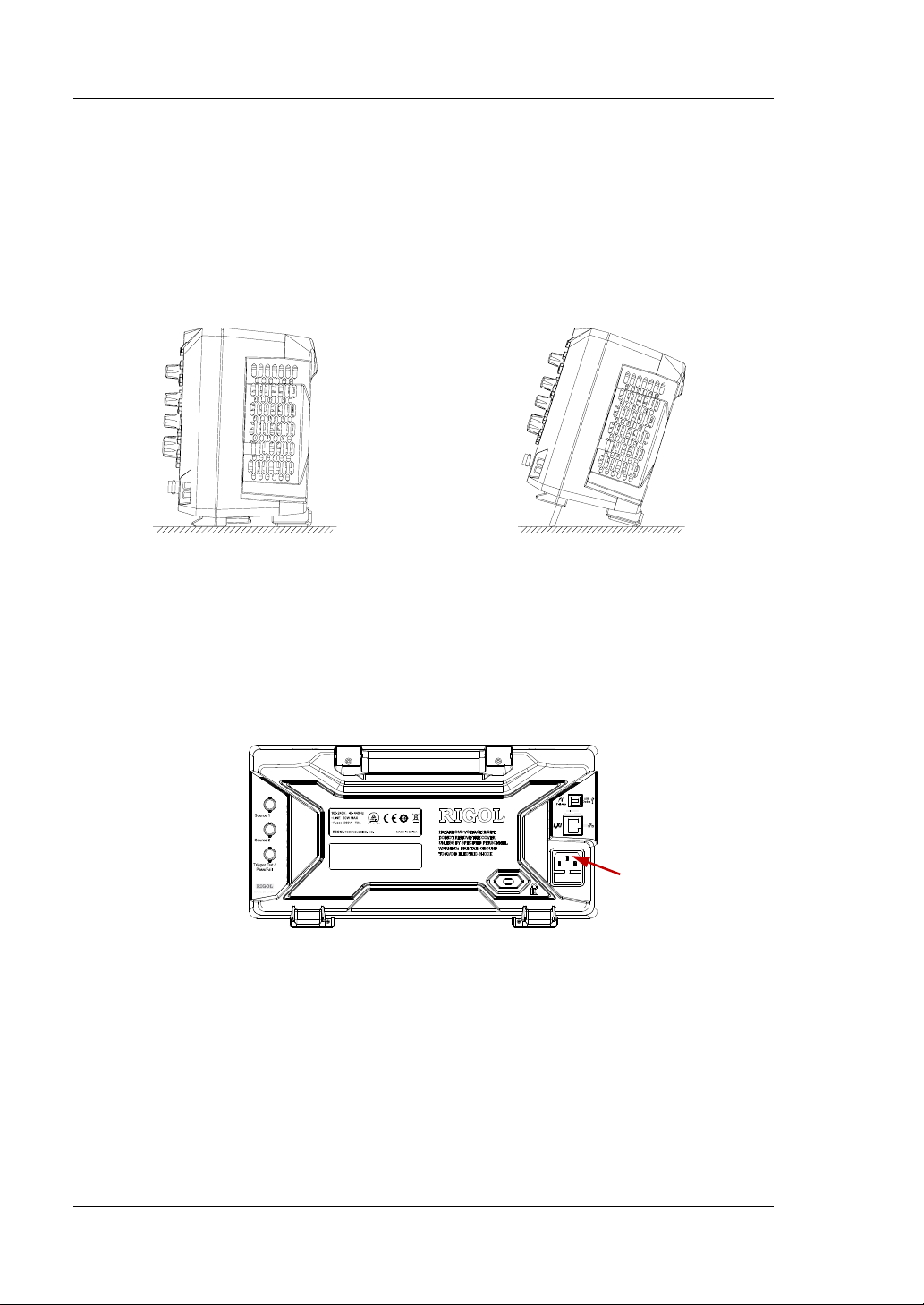
To Adjust the Supporting Legs
Adjust the supporting legs properly to use them as stands to tilt the oscilloscope
upwards for stable placement of the oscilloscope as well as better operation and
observation.
Figure 1-3 To Adjust the Supporting Legs
To Connect to Power Supply
The power requirements of the oscilloscope are 100-240 V, 45-440 Hz. Please use
the power cord supplied with the accessories to connect the oscilloscope to the AC
power source as shown in the figure below.
1-4 MSO1000Z/DS1000Z User’s Guide
Figure 1-4 To Connect to Power Supply
Page 31
Chapter 1 Quick Start RIGOL
Model
Description
RP2200
150 MHz, passive probe
RPL1116
Logic probe
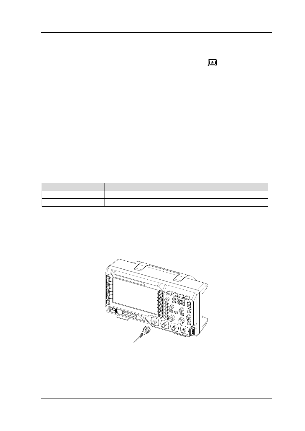
Power-on Inspection
When the oscilloscope is energized, pressing the power key
corner of the front panel can start the oscilloscope. During the start-up process, the
oscilloscope performs a series of self-tests. After the self-test, the welcome screen is
displayed. The instrument is installed with the trial versions of the options before
leaving factory and the remaining trial time is about 2000 minutes. The "Current
Options" dialog box will be displayed if your instrument currently installs the trial
versions of opti ons. F rom this dialog box you can view the name, detail, version and
remaining trial time of the option currently installed.
at the lower-left
To Connect the Probe
RIGOL provides passive probe (standard) for DS1000Z series as well as passive
probe (standard) and logic probe (standard) for MSO1 000Z series. For detailed
technical information of the probes, please refer to the corresponding Probe User’s
Guide. The following are the probes recommended for this oscilloscope.
Connect the passive probe:
1. Connect the BNC terminal of the prob e to an analog channel input terminal of
the oscilloscope at the front panel.
2. Connect the ground alligator clip or spring of the probe to the circuit ground
terminal and connect the probe tip to the circuit point to be tested.
Figure 1-5 To Connect the Passive Probe
MSO1000Z/DS1000Z User’s Guide 1-5
Page 32

RIGOL Chapter 1 Quick Start
Digital Channel Input Terminal
Connect the logic probe:
1. Connect the single-wire terminal of the logic probe to the digital channel input
terminal at the front panel of the oscilloscope in the correct direction.
2. Connect the signal unde r test to the other terminal of t he logic p robe. MSO1000Z
series is provided with the RPL1116 logic probe (standard) which provides two
connecting methods to connect the signal under test to realize convenient and
flexible detection. For the details, please refer to the
Guide
.
RPL1116 Logi c Probe Use r’s
Figure 1-6 To Connect the Logic Probe
Note: The digital channel input terminal does not support hot plug. Please do not
insert or pull out the logic probe when the instrument is powered on.
1-6 MSO1000Z/DS1000Z User’s Guide
Page 33

Chapter 1 Quick Start RIGOL
WARNING
source.
Tip
Compensation Signal Output Terminal
Function Inspection
1. Press Storage Default to restore the oscilloscope to its default
configuration.
2. Connect the earth alligator clip of the p robe to the "Ground Terminal" as shown
in the figure below.
3. Use th e p r obe to co nnect the input terminal of CH1 of the oscilloscope and the
"Compensation Signal Output Terminal" of the prob e.
Ground Terminal
Figure 1-7 To Use the Compensation Signal
4. Press AUTO.
5. Observe the wavefo rm on the display. In normal condition, the square wavef orm
as shown in the figure below should be displayed.
6. Use the same method to test the other channels. If the square waveforms
actually shown do not match that in the figure above, please perform "Probe
Compensation".
To avoid electric shock when using the probe, please make sure that the
insulated wire of the probe is in good condition and do not touch the
metallic part of the probe when the probe is connected to high voltage
The signal output from the probe compensation connector can only be used for
probe compensation adjustment and can not be used for calibration.
MSO1000Z/DS1000Z User’s Guide 1-7
Figure 1-8 Square Waveform
Page 34

RIGOL Chapter 1 Quick Start
Over compensated Perfectly compensated Under compensated
Probe Compensation
When the probes are used for the first time, you should compensate the probes to
make them match the input channels of the oscilloscope. Non-c ompensated or
poorly compensated probes may cause measurement inaccura cy or error. The probe
compensation procedures are as follows.
1. Perform steps 1, 2, 3 and 4 of "Function Inspection".
2. Check the displayed waveforms and compare them with the following figures.
Figure 1-9 Probe Compensation
3. Use a nonmetallic driver to adjust the low-frequency compensation adjustme nt
hole on the probe until the displayed waveform is as the "Perfectly
compensated" in the figure above.
1-8 MSO1000Z/DS1000Z User’s Guide
Page 35

Chapter 1 Quick Start RIGOL
No.
Description
No.
Description
1
Measurement Menu Softkeys
11
Power Key
2
LCD
12
USB Host Interface
3
Function Menu Softkeys
13
Digital Channel Input Interface
[1]
4
Multifunction Knob
14
Analog Channel Input Interface
5
Common Operation Ke ys
15
Logic Analyzer Control Key
[1]
6
CLEAR
16
Signal Source
[2]
7
AUTO
17
VERTICAL Control
8
RUN/STOP
18
HORIZONTAL Control
9
SINGLE
19
TRIGGER Control
10
Help/Print
20
Probe Compensation Sig nal
Output Terminal/Ground Terminal
3 4 5 6 7 8 9 10
1 2
11 12 13 14 15 16 17 18 19 20
Front Panel Overview
Figure 1-10 Front Panel Overview
Table 1-1 Front Panel Descriptions
[1]
Note
Note
: Only applicable to MSO1000Z and DS1000Z Plus.
[2]
: Only applicable to digital oscilloscopes with source channels.
MSO1000Z/DS1000Z User’s Guide 1-9
Page 36
RIGOL Chapter 1 Quick Start
1 2 3
4 5 6 7 8
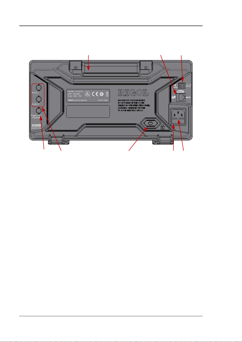
Rear Panel Overview
Figure 1-11 Rear Panel Overview
1. Handle
Pull up the handle vertically for easy carry of the instrument. When you do not
need the handle, press it down.
2. LAN
Connect the instrument to network via this interface for remote control. This
oscilloscope conforms to the LXI CORE 2011 DEVICE class instrument standards
and can quickly build test system with other instruments.
3. USB Device
You can con nect the oscill oscope to a PictBridge printer or PC via this interface.
When a PC is connected, users can send S CPI com mands usin g the PC s oftware
or control the oscilloscope via user-defined programming. When a printer is
connected, users can print the waveform displayed on the screen using the
printer.
4. Trigger Out and Pass/Fail
Trigger Out:
The oscilloscope can output a signal that can reflect the current capture
rate of the oscilloscope at each trigge r via this interf ace. Conne ct t he s ignal
to a wa vef orm displa y dev ice and measu re t he f requ ency of the signal. The
measurement result is the same with the current capture rate.
1-10 MSO1000Z/DS100 0Z U s e r’s Guide
Page 37

Chapter 1 Quick Start RIGOL
Pass/Fail:
The instrument can output a negative pulse via this connector when a failed
waveform is detecte d during the pass/fail test. The instrument continuously
outputs a low level via thi s c onnector when no failed waveform is detected.
5. Source Output
The output terminals of the built-in dual-channel source of the oscilloscope.
When source 1 or source 2 is enabled, the signal currently set can be output
through the [Source 1] or [Source 2] connector at the rear panel.
6. Lock Hole
You can lock the instrument to a fixed location using the security lock (please
buy it yourself) via the lock hole.
7. Fuse
If a new fuse is required, please use the specified fuse (250V, T2A). T he
replacing method is as follows.
a) Turn off the instrument, switch off the power supply and remove the power
cord.
b) Insert a small straight screwdriver into the slot at the power socket and pry
out the fuse seat gently.
c) Take out the fuse and replace it with a specif ied fuse. Then, install the fuse
seat.
8. AC Power Socket
AC power input terminal. The power requirements of this oscilloscope are
100-240 V, 45-440 Hz. Use the power cord provided with the accessories to
connect the instrument to AC power. Then, you can press the power key at the
front panel to start the instrument.
MSO1000Z/DS1000Z User’s Guide 1-11
Page 38
RIGOL Chapter 1 Quick Start
CH1, CH2, CH3, CH4: analog channel
options.
mode between "Coarse" and "Fine".
Tip
SCALE knobs to set the values.
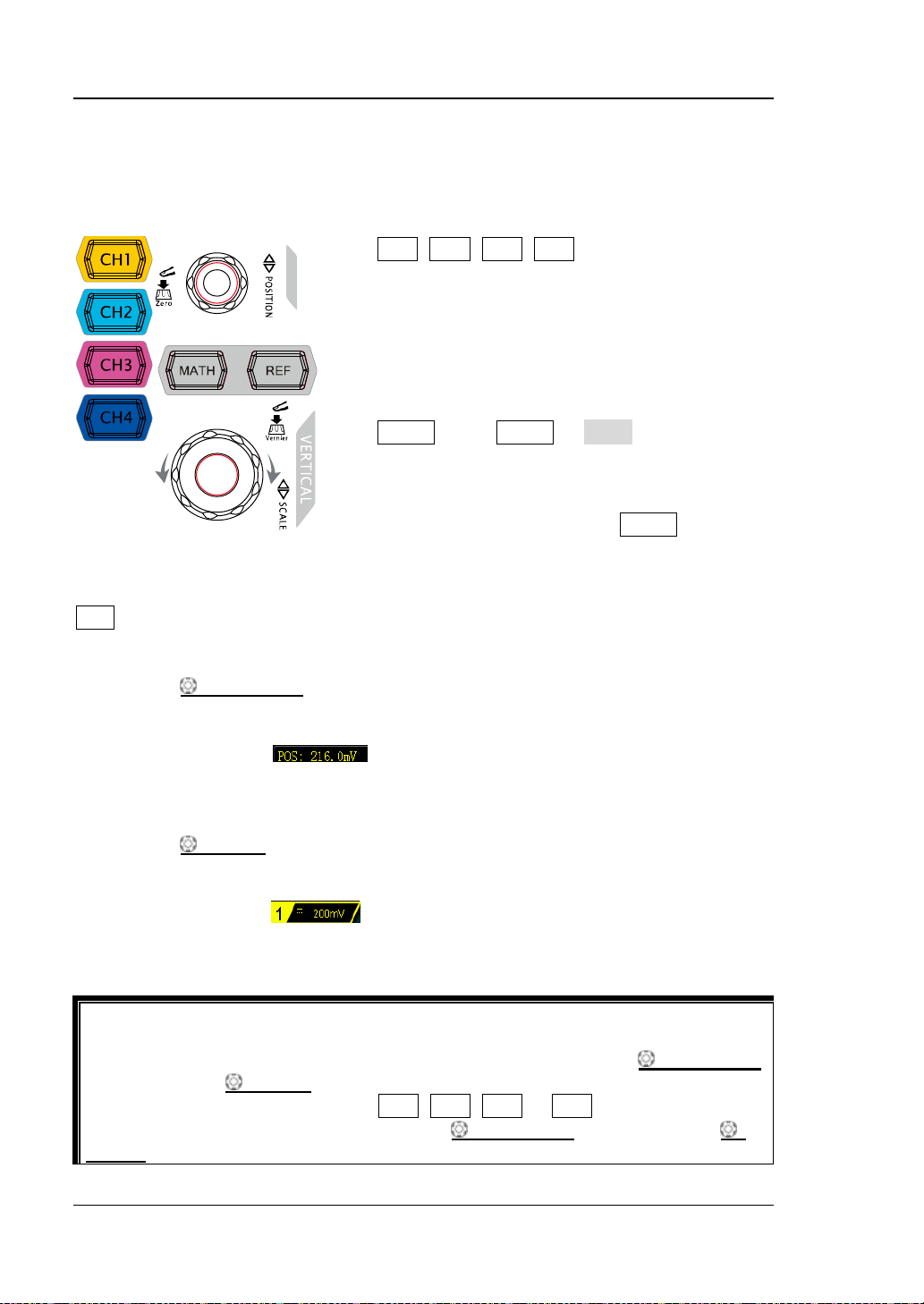
Front Panel Function Overview
VERTICAL
setting keys. The 4 channels are marked by
different colors which are also used to mark
both the corresponding waveforms on the
screen and the channe l input c onnectors. Press
any key to open the corresponding channel
menu and press again to turn off the channel.
MATH: press MATH Math to open the
math operation menu under which A+B, A-B,
A×B, A/B, FFT, A&&B, A||B, A^B, !A, Intg, Diff,
Sqrt, Lg, Ln, Exp, Abs and Filter operations are
provided. You can also press MATH to open
the decoding menu and set the decoding
REF: press this key to enable the reference waveform function to compare the
waveform actually measured with the reference waveform.
VERTICAL
waveform. Turn clockwise to increase the position and turn counterclockwise to
decrease. During the mo dification, the waveform would move up and down and the
position message (e.g.
change ac cordingly. Press down this knob to quickly reset the vertical position to
zero.
VERTICAL
clockwis e to decrease the scale and turn counterclockwise to increase. During the
modification, the display amplitude of the waveform would enlarge or reduce. The
scale information (e.g. ) at the lower side of the screen would change
accordingly. Press down this knob to quickly switch the vertical scale adjustment
How to set the vertical scale and vertical position of each channel?
The 4 channels of MSO1000Z/DS1000Z use the same VERTICAL
and VERTICAL
position of a channel, please press CH1, CH2, CH3 or CH4 at first to select the
desired channel. Then turn the VERTICAL POSITION and VERTICAL
POSITION: modify the vertical position of the current channel
SCALE: modify the vertical scale of the current channel. Turn
SCALE knobs. If you want t o set t he vertical scale and vertical
) at the lower-left corner of the screen would
POSITION
1-12 MSO1000Z/DS100 0Z U s e r’s Guide
Page 39

Chapter 1 Quick Start RIGOL
Press this key to open the logic analyzer control menu. You can turn
any channel or ch annel group, m odify the displa y size of the
each digital channel.
Press this key to ent er the sou rce setting interfa ce. You can enable or
on or off the state display of the current signal.
Logic Analyzer
on or off
digital channel, modify the logic threshold of the digital channel as
well as group the 16 digital channels. You can also set a label for
Note:
― This function is only applicable to MSO1000Z and DS1000Z Plus with the MSO
upgrade option.
― Press LA D7-D0; when "On" is selected, CH4 function is automatically
disabled; when "Off" is selected, CH4 function recovers automatically . P ress LA
D15-D8; when "On" is selected, CH3 function is automatically disabled;
when "Off" is selected, CH3 function recovers automatically.
Signal Source
disable the output of the [Source 1] or [Source 2] connector at
the rear panel, set the output signal waveform and parameters, turn
Note: This function is only applicab le to digital oscilloscopes with source channels.
MSO1000Z/DS1000Z User’s Guide 1-13
Page 40

RIGOL Chapter 1 Quick Start
HORIZONTAL POSITION: modify the horizontal
delayed sweep state.
HORIZONTAL
position. The trigger point would move left or right relative to
the center of the screen when you turn the knob. During the
modification, waveforms of all the cha nnels would m ove left or
right and the horizontal position message (e.g.
) at the upper-right corner of the screen
would change accordingly. Press down this knob to quickly
reset the horizontal position (or the delayed sweep position).
MENU: press this key to open the horizontal contro l menu
where you can turn on or off the delayed sweep function and
switch between different time base modes.
HORIZONTAL
Turn clockwise to reduce the time base and turn
counterclockwise to increase the time base. During the
modification, waveforms of all the channels will be displayed in
expanded or compressed mode and the time base message
(e.g.
accordingly. Press down this knob to quickly switch to the
SCALE: modify the horizontal time base.
) at the upper side of the screen would change
1-14 MSO1000Z/DS100 0Z U s e r’s Guide
Page 41

Chapter 1 Quick Start RIGOL
MODE: press this key to switch the trigger mode to Auto,
move up and down and the value in the trigger level message
Press this key to clear all the waveforms on the screen. If the
displayed.
Press this key to enable th e wavef orm auto setting function . The
TRIGGER
Normal or Single and the corresponding state backlight of
the current trigger mode would be illuminated.
TRIGGER
to increase the level and turn counterclockwise to reduce the
level. During the modification, the trigger level line would
box (e.g. ) at the l ower-left corner of the
screen would change accordingly. Press down the knob to
quickly reset the trigger level to zero point.
MENU: press this key to open the trigger operation menu.
This oscilloscope provides various trigger types. For more
details, please refer to "
FORCE: press this key to generate a trigger signal forcefully.
LEVEL: modify the trigger level. Turn clockwise
To Trigger the Oscilloscope".
CLEAR
oscilloscope is in the "RUN" state, new waveforms will still be
AUTO
Note: Waveform auto setting function requires that the f requency of sine is no l ower
than 41 Hz; the duty cycle should be greater than 1% and the amplitude must be at
least 20 mVpp for square. Otherwise, the Waveform auto setting function may be
invalid and the quick parameter measurement function displayed in the menu will
also be unavailable.
MSO1000Z/DS1000Z User’s Guide 1-15
oscilloscope will automatically adjust the vertical scale,
horizontal time base and trigger mode according to the input
signal to realize optimum wav eform display.
Page 42
RIGOL Chapter 1 Quick Start
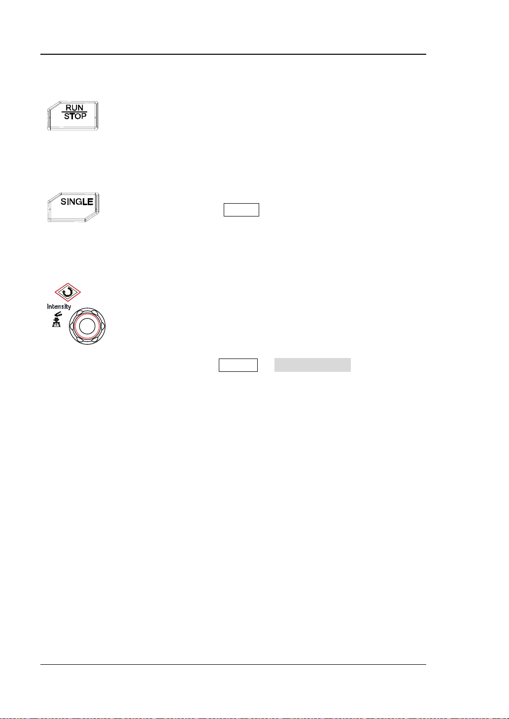
Press this key to "RUN" or "STOP" waveform samp ling. In the
state, the key is illumina ted in re d.
Press this key to set the trigger mode to "Single". In single
immediately.
Adjust waveform brightness:
RUN/STOP
"RUN" state, the key is illuminated in yellow. In the "STOP"
SINGLE
trigger mode, press FORCE to generate a trigger signal
Multifunction Knob
In non-menu-operation mode, turn this knob to adjust the
brightness of waveform display. The adjustable ra ng e is fro m
0% to 100%. Turn clockwise to increase the brightness and
counterclockwise to reduce. Press down this knob to reset the
brightness to 60%.
You can also press Display WaveIntensity and use the
knob to adjust the waveform brightness.
Multifunction:
In menu operation, the backlight of the knob goes on. Press any me nu softkey and
turn the knob to select the submenus under this men u and then p ress down the knob
to select the current submenu. It can also be used to modify parameters (please
refer to the introduction in "Parameter Setting Method ") and input filename.
1-16 MSO1000Z/DS100 0Z U s e r’s Guide
Page 43

Chapter 1 Quick Start RIGOL
Function Menus
Measure: press this key to open the measurement setting menu. You can set the
measurement source, turn on or off the frequency counter, all measure, statistic
function and etc. Press MENU at th e left of the screen to open the measurement
menus of 33 waveform parameters. Then, press down the correspondin g me nu
softkey to quickly realize one-key measurement and the measurement result will be
displayed at the bottom of the screen.
Acquire: press this key to enter the sample setting menu to set the acquisition
mode, Sin(x)/x and memory depth of th e oscilloscope.
Storage: press this key to enter the file store and recall interface. The storable file
types include picture, traces, waves, setups, CSV and parameters. Internal and
external storage as well as disk management are also supported.
Cursor: press this key to enter the cursor measurement menu. The oscilloscope
provides four cursor mo des: manual, tr ack, auto a nd XY. Note that XY cursor mode is
only available when the horizontal time base is set to XY.
Display: press this key to enter the display setting menu to set the display type,
persistence time, wave intensity, grid type and grid brightness.
Utility: press this key to enter the system function setting menu to set the
system-related functions or parameters, such as the I/O, sound and language.
Besides, some advanced functions (such as the pass /fail test, wa vefor m recor d, etc.)
are also supported.
MSO1000Z/DS1000Z User’s Guide 1-17
Page 44

RIGOL Chapter 1 Quick Start
Press this key to print the screen or save the screen to a USB
If a PictBridge printer is connected currently and the printer is
storage device of FAT32 format.
storage device.
―
in idle state, pressing this ke y will ex ecute the print operation.
― If no printer is connected but a USB storage device is inserted,
pressing this key can save the screen to the USB storage
device in the specified format. For more details, please refer to
the introduction in "Storage Type".
― If both a pr i nter and a USB storage device are co nnected at
the same time, the printer enjoys higher priority when
pressing this key.
Note: MSO1000Z/DS1000Z only supports the flash memory USB
1-18 MSO1000Z/DS100 0Z U s e r’s Guide
Page 45
Chapter 1 Quick Start RIGOL
12 13 14 15 16 17 18 19 20 21 22
1 2 3 4 5 6 7 8 9 10 11
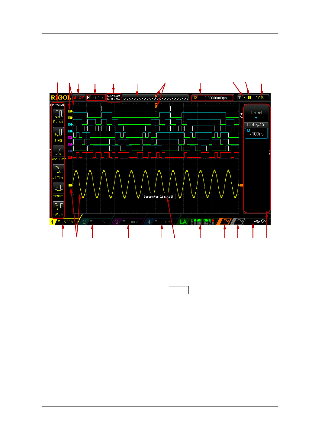
User Interface
MSO1000Z/DS1000Z provides 7.0 inch WVGA (800*480) TFT LCD.
Figure 1-12 User Interface
1. Auto Measurement Items
Provide 16 horizontal (HORIZO NTAL) and 17 vertical (VERTICAL) meas urement
parameters. Press the softkey at the left of the screen to activate the
corresponding measurement item. Press MENU continuously t o switch between
the horizontal and vertical parameters.
2. Digital Chan n el Label/Waveform
The logic high level o f the digital w avef orm is display ed in blue and the logi c low
level in green. Its edge is displayed in white. The waveform of the digital
channel currently selected and the channel label are displayed in red. The digital
channels can be divided into 4 channel groups by the grouping setting function
of the logic analyzer function menu. The channel labels of the same channel
group are displayed in the same color; diff erent channel groups are marked with
different colors.
Note: This function is only a ppli cable to MSO1000Z and DS1000Z Plus with the
MSO upgrade option.
MSO1000Z/DS1000Z User’s Guide 1-19
Page 46
RIGOL Chapter 1 Quick Start
waveform on the screen
waveform in the memory
3. Status
Available states include RUN, STOP, T’D (triggered), WAIT and AUTO.
4. Horizontal Time Base
Represen t the tim e per grid on the horizontal axis on the screen.
Use HORIZONTAL
SCALE to modify this parameter. The range
available is from 5 ns to 50 s .
5. Sample Rate/Memory Dep th
Display the current sample rate and memory depth of the oscilloscope.
The sample rate and memory depth will change in accordance with the
horizontal time base.
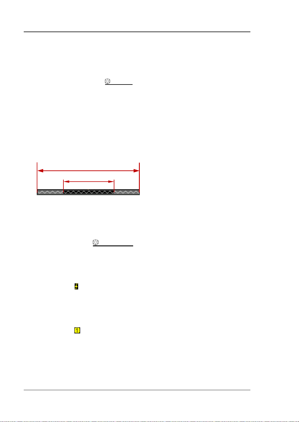
6. Waveform Memory
Provide t he schematic diagram of the memory position of the waveform
currently on the screen.
7. Trigger Position
Display the trigger position of the waveform in the waveform memory and on
the screen.
8. Horizontal Position
Use HORIZONTAL
POSITION to modify this parameter. Press down the
knob to automatically set the parameter to zero.
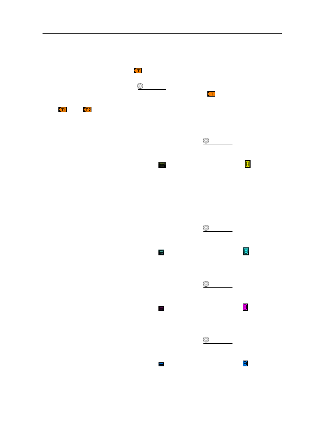
9. Trigger Type
Display the currently selected trigger type and trigger condition setting.
Different labels are displayed when different trigger types are selected.
For example,
represents triggering on the rising edge in "Edge" trigger.
10. Trigger Source
Display the trigger source currently selected (CH1-CH4, AC or D0-D15).
Different labels are displayed when different trigger sources are selected and
the color of the trigger parameter area will change accordingly.
For example,
denot es that CH1 is sel ected as th e trigger source .
1-20 MSO1000Z/DS100 0Z U s e r’s Guide
Page 47
Chapter 1 Quick Start RIGOL
11. Trigger Level
When an analog channel is selected as the trigger source, you need to set a
proper trigger level.
The trigger level label
is displayed at the right of the screen and the
trigger level value is displayed at the upper-right corner of the screen.
When using TRIGGER
level value will change with the up and down of
LEVEL to modify the trigger level, the trigger
.
Note: In slope trigger, runt trigger and window trigger, two trigger level labels
and ) are displayed.
(
12. CH1 Vertical Scale
Display the voltage value per grid of CH1 waveform vertically.
Press CH1 to select CH1, and use VERTICAL
SCALE to modify this
parameter.
The following labels will be displayed according to the current channel
setting: channel coupling (e.g.
) and bandwidth limit (e.g. ).
13. Analog Channel Label/Waveform
Different channels are ma rked with diffe rent colors and the col ors of the channel
label and wavefor m are the same.
14. CH2 Vertical Scale
Display the voltage value per grid of CH2 waveform vertically.
Press CH2 to select CH2, and use VERTICAL
SCALE to modify this
parameter.
The following labels will be displayed according to the current channel
setting: channel coupling (e.g.
) and bandwidt h limit (e.g. ).
15. CH3 Vertical Scale
Display the voltage value per grid of CH3 wa veform vertically.
Press CH3 to select CH3, and use VERTICAL
SCALE to modify this
parameter.
The following labels will be displayed according to the current channel
setting: channel coupling (e.g.
) and bandwidt h limit (e.g. ).
16. CH4 Vertical Scale
Display the voltage value per grid of CH4 waveform vertically.
Press CH4 to select CH4, and use VERTICAL
SCALE to modify this
parameter.
The following labels will be displayed according to the current channel
setting: channel coupling (e.g.
) and bandwidth limit (e.g. ).
17. Messa ge Box
Display the prompt messages.
MSO1000Z/DS1000Z User’s Guide 1-21
Page 48

RIGOL Chapter 1 Quick Start
Denote that the multifunction knob can be used to modify the
status.
Denote that you can use to select the desired items and the item
on after menus with this symbol are selected.
Denote that you can press to open the pop-up nume ric keyboard
constant on after menus with this symbol are selected.
18. Digital Channel Sta tu s A r e a
Display the current status of the 16 digital channels. The digital channels
currently turned on are displayed in green and the digital channel currently
selected is displayed i n red. The digital cha nnels turned off are displaye d in grey.
Note: This function is only a ppli cable to MSO1000Z and DS1000Z Plus with the
MSO upgrade option.
19. Source 1 Waveform
Display the type of waveform currently set for source 1.
When the modulation of source 1 is enabled,
will be displayed below
the source 1 waveform.
When the impedance of source 1 is set to 50 Ω,
will be displayed below
the source 1 waveform.
This function is onl y applicable to digital oscilloscopes with source channels.
20. Source 2 Waveform
Display the type of waveform currently set for source 2.
When the modulation of source 2 is enabled,
will be displayed below
the source 2 waveform.
When the impedance of source 2 is set to 50 Ω,
will be displayed below
the source 2 waveform.
This function is onl y applicable to digital oscilloscopes with source channels.
21. Notification Area
Display the sound ic on and USB stor age device icon.
Sound Icon: Press Utility Sound to enable or disable the sound. When
the sound is enabled, will be displayed; when the sound is disabled,
will be displayed.
USB Storage Device Icon: when a USB storage device is detected,
will
be displayed.
22. Operation Menu
Press any softkey to activate the corresponding menu. The following symbols
might be displayed in the menu:
parameters . The backli ght o f turns on in the parameter modification
currently s elected is displa yed in blue. Press down to enter the menu
bar corresponding to the selected item. The backlight of
and input the desired paramrter values directly. The backlight of is
1-22 MSO1000Z/DS100 0Z U s e r’s Guide
is constant
Page 49

Chapter 1 Quick Start RIGOL
Denote that the current menu has several options.
Denote that the current menu has a lower level menu.
Press this key to return to the previous menu.
The number of dots indicates the number of pages of the current menu.
MSO1000Z/DS1000Z User’s Guide 1-23
Page 50

RIGOL Chapter 1 Quick Start
Parameter Setting Method
MSO1000Z/DS1000Z supports the following two parameter setting methods.
Method one:
For the parameters with
knob
Method two:
For the parameters with
knob
the knob to select the desired value and press down the knob to input the value.
After entering all the v alue s, tu rn t he kn ob t o sele ct t he desired unit and press down
the knob to complete the parameter setting.
directly to set the desired values.
and the numeric keyboard as shown in the figure below is displayed. Turn
displayed on the menu, you can turn the multifunction
displayed on the menu, press down the multifunction
Figure 1-13 Numeric Ke yboard
1-24 MSO1000Z/DS100 0Z U s e r’s Guide
Page 51
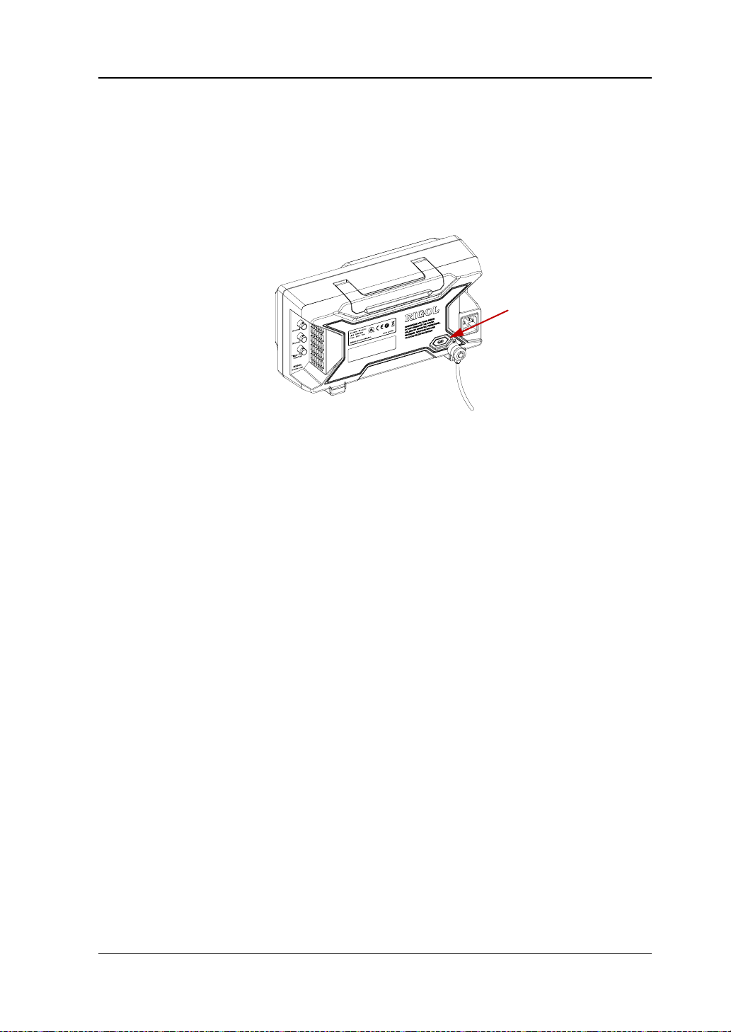
Chapter 1 Quick Start RIGOL
Security Lock Hole
To Use the Security Lock
If needed, you can use the security lock (please buy it yourself) to lock the
oscilloscope to a fixed loca tion. The meth od is as f ollows, ali gn the loc k with the lo ck
hole and plug it into the lock hole vertically, turn the key clockwise to lock the
oscilloscope and then pull the key out.
Figure 1-14 To Use the Security Lock
Note: Please do not insert other articles into the securi ty lock hole to avoid
damaging the instrument.
MSO1000Z/DS1000Z User’s Guide 1-25
Page 52

RIGOL Chapter 1 Quick Start
Help Options Help Display Area
To Use the Built-in Help System
The help system of this oscilloscope provides instructions for all the function keys
(including the menu keys) at the front panel. Press Help to open the help interface
and press again to close t he interface. The hel p interface mainl y consists of two parts.
The left are "Help Options". The right is the "Help Display Area".
Figure 1-15 Help Interface
You can press the button (except the power key
the menu page up/down key
/ ) directly a t the front panel to get the
, the multifunction knob and
corresponding help information in the "Help Display Area".
1-26 MSO1000Z/DS100 0Z U s e r’s Guide
Page 53

Chapter 2 To Set the Vertical System RIGOL
Chapter 2 To Set the Vertical System
The contents of this chapter:
To Enable the Analog Channel
Channel Coupling
Bandwidth Limit
Probe Ratio
Waveform Invert
Vertical Scale
Amplitude Unit
Channel Label
Delay Calibration of the Analog Channel
MSO1000Z/DS1000Z User’s Guide 2-1
Page 54

RIGOL Chapter 2 To Set the Vertical System
To Enable the Analog Channel
MSO1000Z/DS1000Z provides 4 analog input channels (CH1-CH4). As the setting
methods of the vertical systems of the four channels are the same, this chapter takes
CH1 as an example to illustrate the setting method of the vertical system.
Connect a signal to the ch annel connect or of CH 1 and the n p ress CH1 in the vertical
control area (VERTICAL) at the front panel to enable CH1. At this point, the channel
setting menu is displaye d at the ri ght si de of the scr een and the channel status label
at the bottom of the screen (as shown in the figure below) is highlighted. The
information displayed in the channel status label is related to the current channel
setting.
After the channel is turned on, modify the parameters such as the vertical scale,
horizontal time base, trigge r mode and trigger level according to the i nput signal for
easy observation and measurement of th e wav eform.
Channel Coupling
The undesire d signals can be filtered out by setting the coupling mode. For example,
the signal under test is a square waveform with DC offset.
When the coupling mode is "DC": the DC and AC components of the signal un der
test can both pass the channel.
When the coupling mode is "AC": the DC components of the signal under test
are blo cked.
When the coupling mode is "GND": the DC and AC components of the signal
under test are both blocked.
Press CH1 Coupling and use to select the desired coupling mode (the
default is DC). The current coupling mode is displayed in the channel status label at
the bottom of the s creen a s shown in t he figure below . You can also press Coupling
continuously to switch the coupling mode.
DC AC GND
2-2 MSO1000Z/DS1000Z User’s Guide
Page 55

Chapter 2 To Set the Vertical System RIGOL
Attenuation Ratio
amplitude of the signal)
0.01X
1000X
0.01:1
1000:1
Bandwidth Limit
MSO1000Z/DS1000Z supports the bandwidth limit function which can reduce the
display noise. For example, the signal under test is a pulse with high frequency
oscillation.
When the bandwidth limit is disabled, the high frequency components of the
signal under test can pass the channel.
When limiting the bandwidth to 20 MHz, the high frequency components of the
signal under test that exceed 20 MHz are attenuated.
Press CH1, then press BW Limit continuously to switch the bandwidth limit state
(the default is OFF). When the bandwidth limit is enabled, the character "B" will be
displayed in the channel status label at the bottom of the screen.
Note: Bandwidth limit can reduce the noise as well as attenuate or eliminate the
high frequency components of the signal.
Probe Ratio
MSO1000Z/DS1000Z allows user to set the probe attenuation ratio manually. Press
CH1 Probe and use to select the desired probe ratio. The probe ratio values
available are as shown in the table below.
Table 2-1 Probe Ratio
Menu
0.02X
0.05X
0.1X
0.2X
0.5X
1X
2X
5X
10X (the default value)
20X
50X
100X
200X
500X
MSO1000Z/DS1000Z User’s Guide 2-3
(display amplitude of the signal : actual
0.02:1
0.05:1
0.1:1
0.2:1
0.5:1
1:1
2:1
5:1
10:1
20:1
50:1
100:1
200:1
500:1
Page 56

RIGOL Chapter 2 To Set the Vertical System
(b) "Invert" On
Waveform Invert
Press CH1 Invert to turn on or off waveform invert. When waveform invert is
turned off, the waveform display is normal; when waveform invert is turned on, the
waveform voltage values are inverted (as shown in the figures below).
(a) "Invert" Off
Figure 2-1 Waveform Invert
Vertical Scale
Vertical scale refers to the voltage value per grid in the vertical direction on the
screen and is usually expressed as V/div.
Press CH1 and rotate VERTICAL
to reduce the scale and counterclockwise to increase). The size of the displayed
waveform will be changed accordingly. The scale information (as s hown in t he figure
below) in the channel label at the bottom of the screen will change accordingly
during the adjustment. The adjustable range of the vertical scale is related to the
probe ratio currently set. By default, the p robe rati o is 10X and the a djustable range
of the vertical scale is from 10 mV/div to 100 V/div.
The vertical scale can be adjusted in "Coarse" or "Fine" mode. Press CH1
Volts/Div to switch the adjustment mode.
Coarse adjustment (take counter clockwise as an example): s et the v ertical scale
in 1-2-5 step namely 10 mV/div, 20 mV/div, 50 mV/div, 100 mV/div…100 V/div.
Fine adjustment: further adjust the vertical scale within a relatively smaller
range to improve vertical resolution. If the a mplitu de of the input waveform is a
little bit greater than the full scale under the current scale and the amplitude
would be a little bit lower if the next scale is used, fine adjustment can be used
to improve the amplitude of waveform display to view signal details.
Note: You can also press VERTICAL
SCALE to adjust the vertical scale (clockwise
SCALE to quickly swit ch between "Coarse"
2-4 MSO1000Z/DS1000Z User’s Guide
Page 57
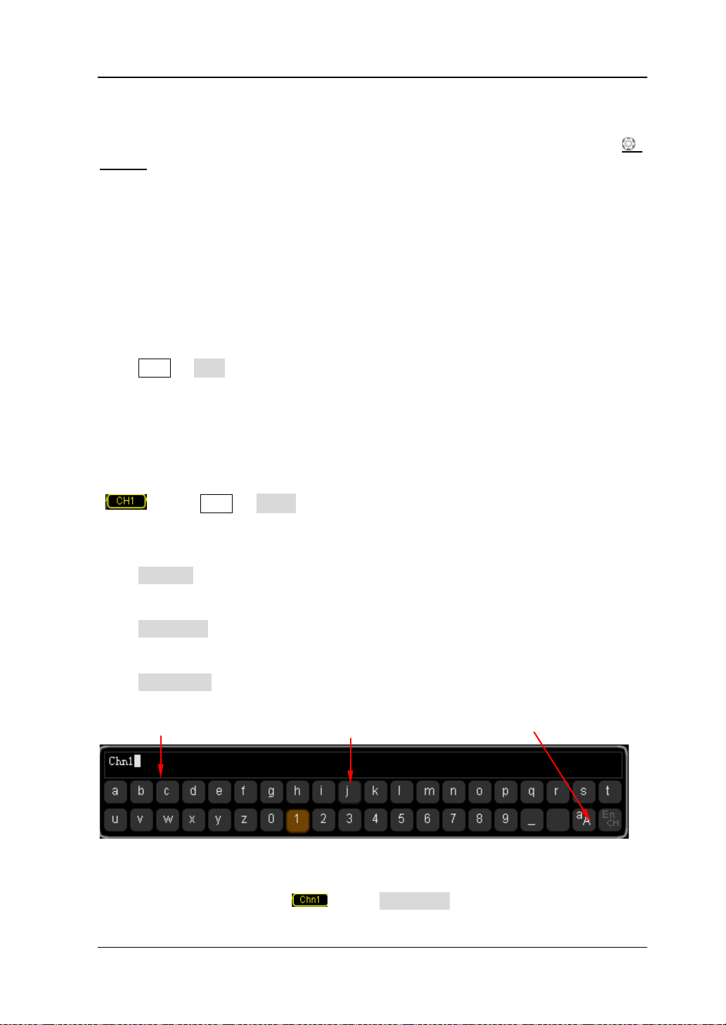
Chapter 2 To Set the Vertical System RIGOL
Name Input Area Keyboard Upper/Lower Case Switch
and "Fine" adjustments.
When changing the vertical scale of the analog channel by rotating VERTICAL
SCALE, you can select to expand or compress the waveform around the "Center" or
"Ground". For more details, please refer to the introduction in "
Reference".
Vertical
Amplitude Unit
Select the amplitude displ ay unit f or the cur rent channel. The av ailable units a re W, A,
V and U. When the unit is changed, the unit displayed in the channel label will
change accordingly.
Press CH1 Unit to select the desired unit and the default is V.
Channel Label
The instrument uses the number of the channel to mark the corresponding channel
by default. For ease of use, you can also set a label for each channel, for example,
" ". Press CH1 Label to enter the label setting menu. You can use the
built-in label or manually input a label. Manual input does not support the Chinese
input, and the length of the label cannot exceed 4 characters.
Press Display to turn on or off the channel label display. The default is CH1 when
the channel label display is enabled.
Press Template to select the preset labels such as CH1, ACK, ADDR, BIT, CLK, CS,
DATA, IN, MISO, MOSI, OUT, RX and TX, etc.
Press Label Edit and the label editing interface is automatically displayed as shown
in the figure below. You can input the label manually.
Figure 2-2 Label Editing Interface
For example, set the label to " ". Press Keyboard to select the "Keyboard" area.
MSO1000Z/DS1000Z User’s Guide 2-5
Page 58

RIGOL Chapter 2 To Set the Vertical System
Select "Aa" using and press down to swi tch it to "aA". Select "C" using
and press down
to input the character. Use the same method to input "hn1".
After finishing the input, press OK to finish the editing. If the Display is enabled,
the label
will be displayed at the left of CH1 waveform.
T o modify or delete the input character, press Name to select the "Name In put Area "
and use
to select the character to be modified or deleted. Enter the desired
character or press Delete to delete the character selected.
2-6 MSO1000Z/DS1000Z User’s Guide
Page 59

Chapter 2 To Set the Vertical System RIGOL
Horizontal Time Base
Delay Calibration Time Step
5 ns
100 ps
10 ns
200 ps
20 ns
400 ps
50 ns
1 ns
100 ns
2 ns
200 ns
4 ns
500 ns
10 ns
1 μs to 10 μs
20 ns
Delay Calibration of the Analog Channel
When using an oscilloscope for actual measurement, the transmission delay of the
probe cable may bring relatively greater error (zero offset). MSO1000Z/DS1000Z
supports user to set a delay time to calibrate the zero offset of the corresponding
channel. Zero offset is defined as the offset of the crossing point of the waveform
and trigger level line relative to the trigger position, as shown in the figure below.
Figure 2-1 Zero Offset
Press CH1 Delay-Cal and use to set the desired delay time. The range
available is from -100 ns to 100 ns. Pressing down the multifunction knob will
reset the delay time to 0.00 s.
Note: This parameter is related to the instrument model and the current horizontal
time base setting. The larger the horizontal time base is, the larger the setting step
will be. Take MSO1104Z-S as an example. The step values under differen t horizontal
time base ar e as shown in the table below.
Table 2-2 Relation between delay calibration time step and horizontal time base
Note: When the horizontal time base is equal to or greater than 10 μs, the delay
calibration time cannot be adjusted .
MSO1000Z/DS1000Z User’s Guide 2-7
Page 60

Page 61

Chapter 3 To Set the Horizontal System RIGOL
Chapter 3 To Set the Horizontal System
The contents of this chapter:
Delayed Sweep
Time Base Mode
MSO1000Z/DS1000Z User’s Guide 3-1
Page 62

RIGOL Chapter 3 To Set the Horizontal System
Main time
The waveform before
The waveform after enlargement
Delayed Sweep
Delayed sweep can be used to enlarge a length of waveform horizontally to view
waveform details.
Press MENU in the horizontal control area (HORIZONTAL) at the front panel and
press Delayed to enable or disable delayed sweep.
Note: To enable delayed sweep, the current time base mode must be "YT".
In delayed sweep mo de, t he s creen is divide d into t wo dis play a reas as show n in the
figure below.
base
Delayed
Sweep
Time Base
enlargement
The waveform before enlargement:
The waveform in the area that is not covered by subtransparent blue in the upper
part of the screen is the waveform before enlargement. You can turn HORIZONTAL
POSITION to move the area left an d right or turn HORIZONTAL SCALE to
enlarge or reduce this area.
The waveform after enlargement:
The waveform in the l ower part of the screen is the h orizontally expande d wav eform.
Compared to the main time base, the delayed time base has increased the waveform
resolution (as shown in the fig ure above).
Note: The delayed time base should be less than or equal to the main time base.
3-2 MSO1000Z/DS1000Z User’s Guide
放大后的波形
Figure 3-1 Delayed Sweep Mode
Page 63
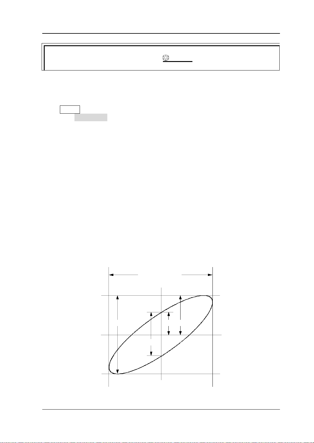
Chapter 3 To Set the Horizontal System RIGOL
Tip
to directly switch to the delayed sweep mode.
II I
III IV
The signal must be
A B C
D
II I
III IV
The signal must be
You can also p ress down HORIZONTAL SCALE (delayed sweep shortcut key)
Time Base Mode
Press MENU in the horizontal control area (HORIZONTAL) at the front panel and
then press Time Ba se to select the time base mode of the oscilloscope. The default
is YT.
YT Mode
In this mode, the Y axis represents voltage and the X axis represents time.
Note: Only when this mode is e nabled, can "Delayed Sweep" be turned on. In this
mode, when the horizontal time base is greater than or equal to 200 ms, the
instrument enters slow swee p mo de . For the details, please refer to the introduction
of slow sweep in "Roll Mode".
XY Mode
In this mode, the oscilloscope changes the two channels from voltage-time display
mode to voltage -voltage display mode. The phase deviation between two signals
with the same frequency can be easily measured via Lissajous method. The figure
below shows the measurement schematic diagram of the phase deviation.
centered horizontally
Figure 3-2 Measurement Schematic Diagram of Phase Deviation
centered horizontally
MSO1000Z/DS1000Z User’s Guide 3-3
Page 64

RIGOL Chapter 3 To Set the Horizontal System
According to sinθ=A/B or C/D (wherein, θ is the phase deviation angle between
the two channels and the definitions of A, B, C and D are as shown in the figure
above), the phase deviation angle is obtained, that is:
θ=±arcsin (A/B) or ±arcsin (C/D)
If the principal axis of the ellipse is within quadrant I and III, the phase deviation
angle obtained should be within quadr ant I an d IV, namely within (0 to π/2) or (3π/2
to 2π). If the principal axis of the ellipse is within quadrant II and IV, the phase
deviation angle obtained s hould be wit hin qua dr ant II an d III, namel y within (π/2 to
π) or (π to 3π/2).
The XY function can be used to measure the phase deviation occurred when the
signal under test passes through a circuit network. Connect the oscilloscope to the
circuit to monitor the input and output signals of the circuit.
Application example: measure the phase deviation of the input signals of two
channels.
Method 1: Use Lissajous method
1. Connect a sine signal to CH1 and then connect a sine signal with the same
frequency and amplitude but a 90° phase deviation to CH2.
2. Press AUTO and then adjust the vertical positions of CH1 and CH2 to 0 V.
3. Set the time base mode to XY, press X-Y and select "CH1-CH2". Rotate
Horizontal
SCALE to adjust the sample rate properly to get better
Lissajous figure for bet t e r obs e rvation and me a s urement.
4. Rotate VERTICAL SCALE of CH1 and CH2 to make the signals easy to
observe. At this point, the circle as shown in the figure below should be
displayed.
5. Observe the measurement result shown in the figure above. According to the
measurement schematic diagram of the phase deviation (as shown in Figure
), A/B (C/D) = 1. Thus, the phase deviation angle θ=±arcsin1=90°.
3-2
3-4 MSO1000Z/DS1000Z User’s Guide
Page 65

Chapter 3 To Set the Horizontal System RIGOL
Slow Sweep
observe low frequency signal, DC "Channel Coupling" mode is recommended.
Note:
The maximum sample rate of XY mode is 500 MSa/s. Generally, longer sample
waveform can ensure better display effect of Lissajous figure. But due to the
limitation of the memory depth, you have to r educe th e waveform s ample rate
to acquire longer waveform (refer to the introduction in "Memory Depth").
Therefore, during the measurement, reducing the sample rate properly can
acquire better display effect of Lissajous figure.
When XY mode is enabled, "Delayed Sweep" will be disabled automatically.
Press X-Y to select "CH1-CH2, CH1-CH3, CH1-CH4, CH2-CH3, CH2-CH4,
CH3-CH4". After you choose a ny o f t h e opt i ons, the instrument automatically
turns on the two corresponding channels and turns off the other two channels.
The X-axis tracks the vo ltage of the first channel in each option; the Y-axis
tracks the voltage of the second channel in each option.
The following functions are not available in XY mode:
"Delayed Sweep", "Vectors", "Pro to c ol Decoding", "Acquisition Mode",
"Pass/Fail Test", "W aveform Record" "Digital Channel" and "To Set the
Persistence Time
Method 2: Use the shortcut measurement function
Please refer to "Pha se 12 " and "Phase 12 " measurement fun ctio ns of "Delay
and Phase" on page 6-27.
".
Roll Mode
In this mode, the waveform scrolls from right to left to update the display.
The horizontal position and trigger control of the waveform are not available. The
range of horizontal scale adjustment is from 200 ms to 50.0 s.
Note: When R oll mode is enabled, the w av eform "horizontal position", "Delayed
Sweep", "Protocol Decoding", "Pass/Fail Test", "Waveform Record", "To
Set the Persistence Time" and "To Trigger the Oscilloscope" are not available.
Slow sweep is similar to Roll mode. In YT mode, when the horizontal time base is
set to 200 ms/div or slower, the instrument enters "slow sweep" mode in which the
instrument first acquires the data at the left of the trigger point an d then waits for a
trigger event. After the trigger occurs, the instrument continues to finish the
waveform at the right of the trigger point. When slow sweep mode is used to
MSO1000Z/DS1000Z User’s Guide 3-5
Page 66

Page 67

Chapter 4 To Set the Sample System RIGOL
Chapter 4 To Set the Sample System
The contents of this chapter:
Acquisition Mode
Sin(x)/x
Sample Rate
Memory Depth
Antialiasing
MSO1000Z/DS1000Z User’s Guide 4-1
Page 68

RIGOL Chapter 4 To Set the Sample System
Acquisition Mode
The acquisition mode is used to control how to generate waveform points from
sample points.
Press Acquire Mode at the front panel and use to select the desired
acquisition mode (the default is normal), then press down the knob to select this
mode. You can also press Mode continuously to switch the acquisition mode.
Normal
In this mode, the oscilloscope sam ples the signal at equal time int erval to re build th e
waveform. For most of the waveforms, the best display effect can be obtained using
this mode.
Peak Detect
In this mode, the oscilloscope acquires the maximum and minimum values of the
signal within the sample in terval to get the envel ope of the signal or the narrow pulse
of the signal that might be lost. In this mo de, s ignal confusion can be prevented but
the noise displayed would be larger.
In this mode, the oscilloscope can display a ll the pulses with pulse widths at least as
wide as the sample period.
Average
In this mode, the oscilloscope averages the waveforms from multiple samples to
reduce the random noise of the input signal and improve the vertical resolution.
Greater number of averages can lower the noise and increase the vertical resolution;
while at the same time, it will slow the respons e of the displayed waveform to the
waveform changes.
When "Average" mode is selected, press Averages and us e to set the desired
number of averages. The number of ave r ages can be set to 2, 4, 8, 16, 32, 64, 128,
256, 512 or 1024. The default is 2.
4-2 MSO1000Z/DS1000Z User’s Guide
Page 69

Chapter 4 To Set the Sample System RIGOL
Figure 4-1 The Waveform before Average
Figure 4-2 The Waveform after 256 Averages
High Resolution
This mode uses a kind of ultra-sample technique to average the neighboring points
of the sample waveform to reduce the random noise on the input signal and gener ate
much smoother waveforms on the screen. This is generally used when the sample
rate of the digital converter is hi gher than the st orage r ate of the a cquisition memory.
Note: "Average" and "High Res" modes use different averaging methods. The
former uses "Multi-sample Average" and the latter uses "Single Sample Average".
MSO1000Z/DS1000Z User’s Guide 4-3
Page 70

RIGOL Chapter 4 To Set the Sample System
Sin(x)/x
Press Sin(x)/x to enable or disable the dynamic sine interpolation function which
can acquire better restoration of the origina l wavefor m.
Note: If the number of ch annels cu rrent ly turned on is less than three, Sin(x)/x is
grayed out and disabled.
Sample Rate
The maximum sample rate of MSO1000Z/DS1000Z is 1 GSa/s.
Note: The sample rate is displayed in the status bar at the upper side of the screen
and in the Sa Rate menu and can be changed by adjusting the horizontal time base
through HORIZONTAL
The influence on the waveform when the sample rate is too low:
1. Waveform Distortion: when the sample rate is too low, some waveform
details are lost and the waveform displayed is rather different from the actual
signal.
SCALE or modifying the "Memory Depth".
2. Waveform Confusion: when the sample rate is lower than twice the actual
signal frequency (Nyquist Frequency), the frequency of the waveform rebuilt
from the sample data is lower than the actual signal frequency.
4-4 MSO1000Z/DS1000Z User’s Guide
Page 71

Chapter 4 To Set the Sample System RIGOL
Pulse
3. Waveform Leakage: when the sample rate is too low, the waveform rebuilt
from the sample data does not reflect all the actual signal information.
disappeared
MSO1000Z/DS1000Z User’s Guide 4-5
Page 72

RIGOL Chapter 4 To Set the Sample System
T
Trigger Point
Pre-sample
Delayed Sample
Memory Depth
MDepth SRate TScale HDivs=××
MDepth
SRate
TScale
HDivs
Memory Depth
Memory depth refers to the number of waveform points that the oscilloscope c a n
store in a single trigger sample and it reflects the storage ability of the sample
memory. MSO1000Z/DS1000Z provides up to 24 Mpts memory depth (optional) and
12 Mpts standard memory depth.
Figure 4-1 Memory Depth
The relation of memory depth, sample rat e and horiz ontal ti me base s cale fulfills the
equation below:
: Memory depth. The unit is pts.
: Sample rate. The unit is Sa/s.
: Horizontal time base scale. The unit is s/div.
: Number of grids horizontally. The unit is div. For MSO1000Z/DS1000Z, this
value is 12.
Therefore, under the same horizontal time base scale , higher memory dept h can
ensure higher sample rate.
Press Acquire Mem Depth, use to switch to the desired memory depth (the
default is auto) and then press down the knob to select the option. You can also
press Mem Depth continuously to switch the memory depth.
For analog channels:
― When a single channel is enabled, the memory depths available include
Auto, 12kPoints, 120kPoints, 1.2MPoints, 12MPoints and 24MPoints
(optional).
― When du al channels are enabled, the memory depths available include Auto,
6kPoints, 60kPoints, 600kPoints, 6MPoints and 12MPoints (optional).
― When three or four channels are enabled, the memory depths available
include Auto, 3kPoints, 30kPoints, 300kPoints, 3MPoints and 6MPoints
(optional).
(4-1)
4-6 MSO1000Z/DS1000Z User’s Guide
Page 73

Chapter 4 To Set the Sample System RIGOL
For digital channels:
― When 8 channels are enabled, the memory depths available include Auto,
12kPoints, 120kPoints, 1.2MPoints, 12MPoints and 24MPoints (optional).
― When 16 channels are en abled , the memory depths available include Auto,
6kPoints, 60kPoints, 600kPoints, 6MPoints and 12MPoints (opt ional).
Note: In "Auto" mode, the oscilloscope selects the memory depth automatically
according to the current sample rate.
Antialiasing
At slower sweep speed, the sample rate is reduced and a dedicated display algorithm
can be used to minimize the possibility of aliasing.
Press Acquire Anti-aliasing to enable or disable the antialiasing function. By
default, antialiasing is disabled and waveform aliasing is more possible.
MSO1000Z/DS1000Z User’s Guide 4-7
Page 74

Page 75

Chapter 5 To Trigger the Oscilloscope RIGOL
Chapter 5 To Trigger the Oscilloscope
As for trigger, you set certain trigger condition according to the requirement and
when a waveform in the waveform stream meets this condition, the oscilloscope
captures this waveform as well as the neighbouring part and displays them on the
screen. For digital oscilloscope, it samples wa veform continuously n o matter wh ether
it is stably triggered, but only stable trigger can ensure stable display. The trigger
module ensures that every time base sweep or acquisition starts from the
user-defined trigger condition, namely every sweep is synchronous to the acquisition
and the waveforms acq u ired overlap to displ ay sta ble waveform.
Trigger setting should be based on t he features of the input signal, thus you n eed to
have some knowledge of the signal under test to quickly capture the desired
waveform. This os cilloscope provides abundant adv anced trigger f unctions which can
help you to focus on t he desired waveform details.
The contents of this chapter:
Trigger Source
Trigger Mode
Trigger Coupling
Trigger Holdoff
Noise Rejection
Trigger Type
Trigger Output Connector
MSO1000Z/DS1000Z User’s Guide 5-1
Page 76

RIGOL Chapter 5 To Trigger the Oscilloscope
Trigger Source
Press MENU Source in the trigger control area (TRIGGER) at the front panel to
select the desi red tri gger s ource. A nalog channels CH1-CH4, digital c hannels D0-D15
or the AC Line can all be used as trigger source.
Analog channel input:
Signals input from analog channels CH1-CH4 can all be used as trigger source. No
matter whether the channel selected is enabled, the channel can work normally.
Note: When any channel among D7-D0 is enabled, CH4 cannot be us e d as trigger
source; when any channel among D15-D8 is enabled, CH3 cann ot be used as tr igger
source.
Digital ch an n e l in p ut:
Only the digital channels turned on can be used as trigger source. Please refer to the
introduction of "To Turn on/off the Digital Channel" to turn on the desired
digital channel.
AC line:
The trigger signal is obtained f rom the AC power input o f the oscilloscope. AC t rig ger
is usually used to measure signals relevant to the AC powe r fre que n cy. For exampl e ,
stably trigger the waveform output from the transformer of a transformer substation;
it is mainly used in related measurements of the power industry.
5-2 MSO1000Z/DS1000Z User’s Guide
Page 77
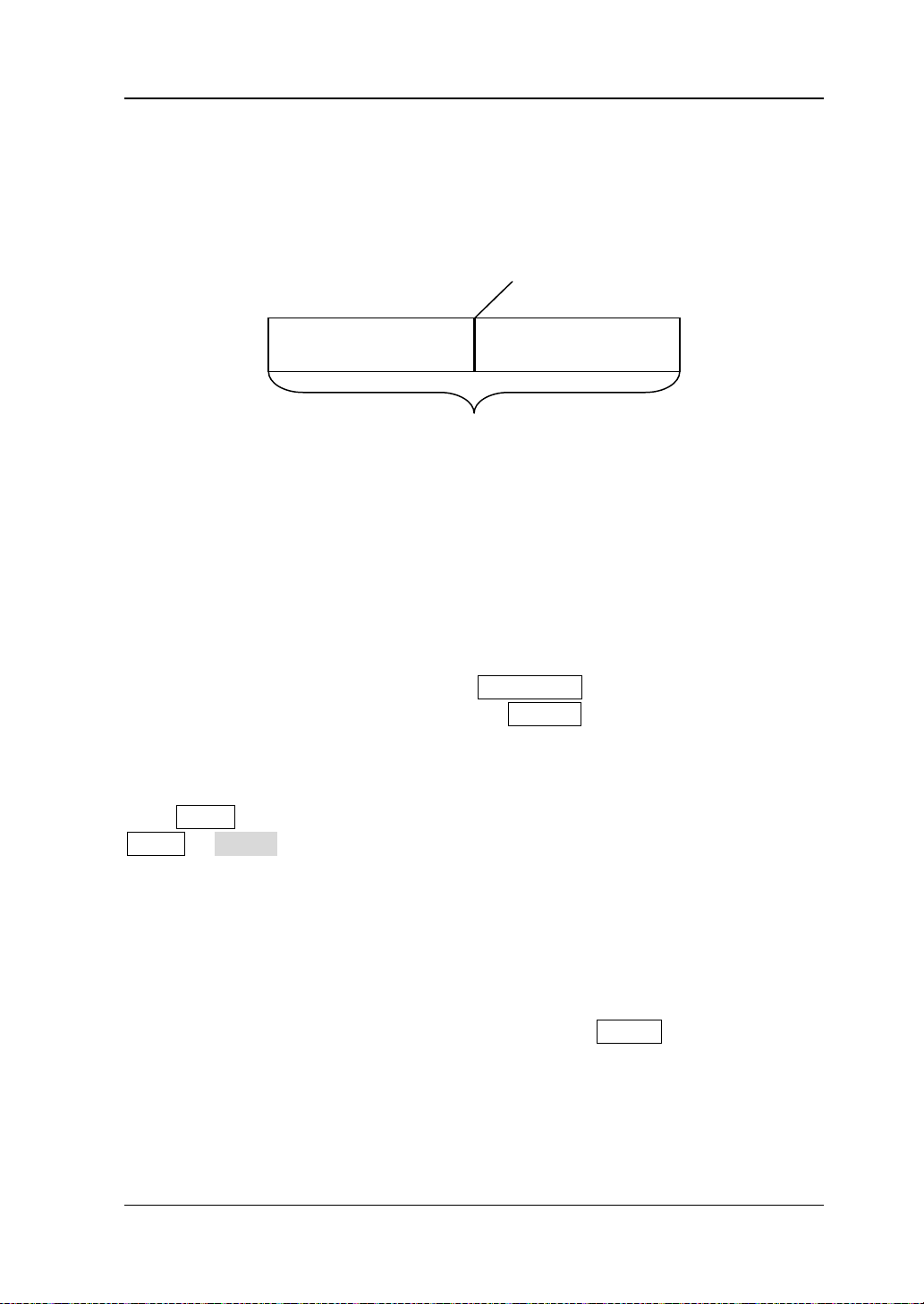
Chapter 5 To Trigger the Oscilloscope RIGOL
Pre-trigger Buffer
Post-trigger Buffer
Trigger Event
Acquisition Memory
Trigger Mode
The following is the schematic diagram of the acquisition memory. To easily
understand the trigger event, the acquisition memory is divided into the pre-trigger
buffer an d pos t-trigger buffer.
Figure 5-1 Schematic Diagram of the Acquisition Memor y
After the system runs, the oscilloscope operates by first filling the pre-trigger buffer.
It starts searching for a trigger after the pre-trigger buffer is filled. While searching
for the trigger, the data sampled will still be transmitted to the pre-trigger buffer (the
new data will continuously ove rwrite the previous date). When a trig ger is f ound, th e
pre-trigger buffer contains the data acquired just before the trigger. Then, the
oscilloscope will fill the post-trigger buffer and display the data in the acquisition
memory. If the acquisition is activated via RUN/STOP, the oscilloscope will repeat
this process; if the acquisition is activated via SINGLE, the oscilloscope will stop
after finishing a single acquisition (you can pan and zoom the waveform currently
displayed).
Press MODE in the trigger control area (TRIGGER) at the front panel or press
MENU Sweep to select the desired trigger mode. The corresponding s tatu s li ght
of the mode currently selected turns on.
Auto: in this trigger mode, the oscilloscope will force a trigger if the specified
trigger condition is not found.
Normal: in this trigger mode, the oscilloscope only triggers when the specified
trigger condition is found.
Single: in this trigger mode, the oscilloscope generates a trigger when the
specified trigger condition is found and then stops.
Note: In "Normal" and "Single" trigger modes, pressing FORCE can generate a
trigger signal forcibly.
MSO1000Z/DS1000Z User’s Guide 5-3
Page 78

RIGOL Chapter 5 To Trigger the Oscilloscope
Trigger Coupling
Trigger coupling decides which kind of components will be transmitted to the trigger
module. Please distinguish it from "Channel Coupling".
DC: allow DC and AC components into the trigger path.
AC: block all the DC components and attenuate signals lower than 75 Hz.
LF Reject: block the DC components and reject the low frequency components
(lower than 75 kHz).
HF Reject: reject the high frequency components (higher than 75 kHz).
Press MENU Setting Coupling in the trigger control area (TRIGGER) at the
front panel to select the desired coupling type (the default is DC).
Note: Trigger coupling is only valid in edge trigger.
5-4 MSO1000Z/DS1000Z User’s Guide
Page 79
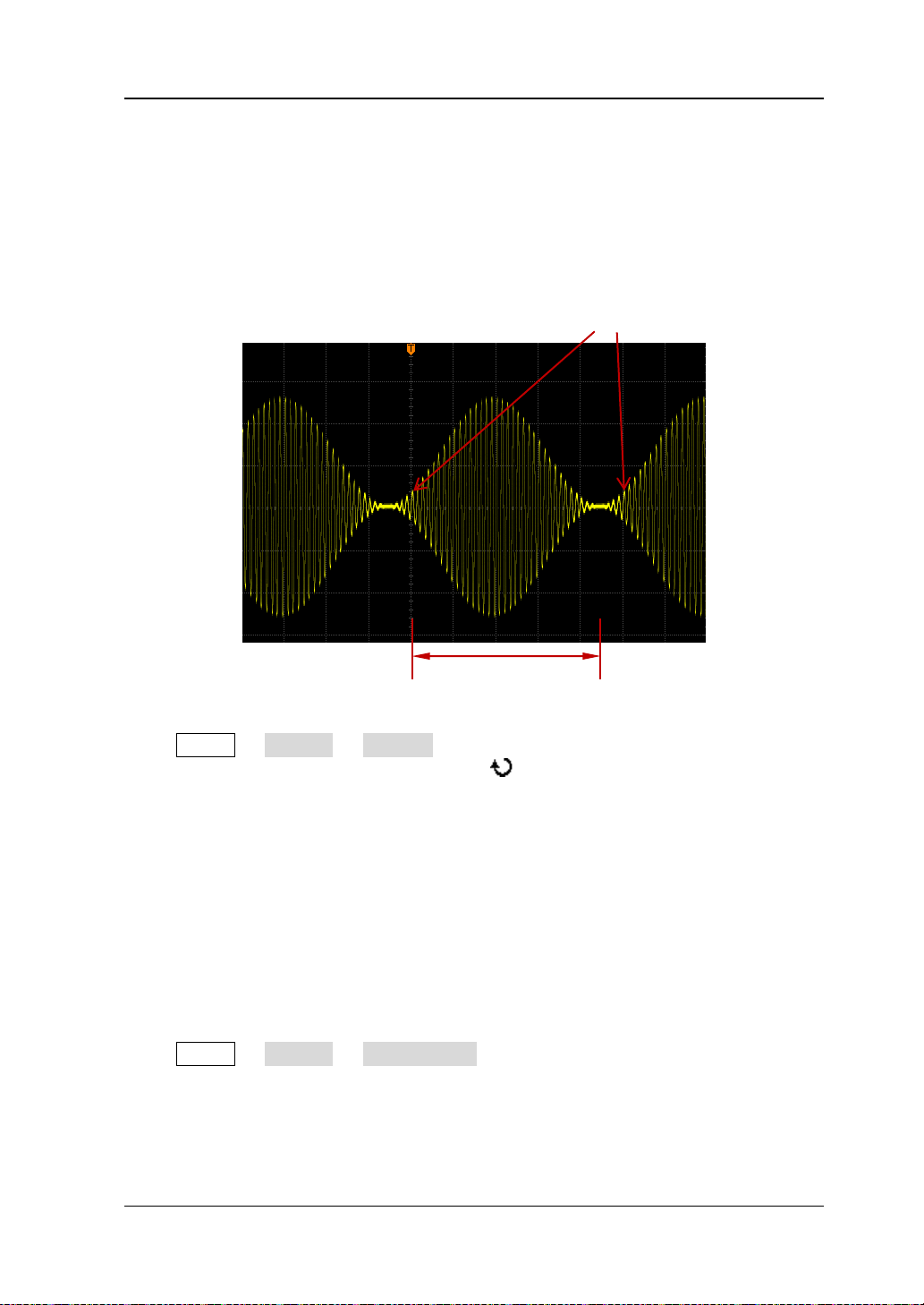
Chapter 5 To Trigger the Oscilloscope RIGOL
Trigger Position
Holdoff Time
Trigger Holdoff
Trigger hol doff can be used to stably trigger complex waveforms (such as mod ulated
waveform). Holdoff time is the am ount of time that the oscilloscope waits for
re-arming the trigger module after generating a correct trigger. The oscilloscope will
not trigger even if the trigger condition is met during the holdoff time and will only
re-arm the trigger module after the holdoff time expires.
Figure 5-2 Schematic Diagram of Trigger Holdoff
Press MENU Setting Holdoff in the trigger control area (TRIGGER) at the
front panel and use the multifunction knob to modify the holdoff time (the
default is 16 ns) until the waveform triggers stably. The adjustable range of h oldoff
time is from 16 ns to 10 s.
Note: Trigger holdoff is not available for video trigger, timeout trigger, setup/hold
trigger, Nth edge trigger, RS232 trigger, I2C trigger and SPI trigger.
Noise Rejection
Noise rejection can reject the high frequency noise in the signal and re du ce the
possibility of miss-trigger of the oscilloscope.
Press MENU Setting NoiseReject in the trigger control area (TRIGGER) at
the front panel to enable or disable noise rejection.
Note: This function is not available when the current trigger source is a digital
channel.
MSO1000Z/DS1000Z User’s Guide 5-5
Page 80

RIGOL Chapter 5 To Trigger the Oscilloscope
Trigger Type
MSO1000Z/DS1000Z provides various trigger functions, including various serial bus
triggers.
Edge Trigger
Pulse Trigger
Slope Trigger
Video Trigger
Pattern Tr igg er
Duration Trigger
TimeOut Trigger (Optional)
Runt Trigger (Optional)
Window Trigger (Optional)
Delay Trigger (Optional)
Setup/Hold Trigger (Optional)
Nth Edge Trigger (Optional)
RS232 Trigger (Optional)
I2C Trigger (Optional)
SPI Trigger (Optional)
5-6 MSO1000Z/DS1000Z User’s Guide
Page 81

Chapter 5 To Trigger the Oscilloscope RIGOL
Edge Trigger
Trigger on the trigger threshold of the specified edge of the input signal.
Trigger Type:
Press Type, rotate to select "Edge" and press down . At this point, the t rigger
setting information is displayed at the upper right corner of the screen.
For example,
is CH1; the trigger level is 0.00 V.
Source Selection:
Press Source to open the signal source list and select CH1-CH4, AC or D0-D15. For
the details, please refe r to the int roduction in "
source is displayed at the upper right corner of the screen.
Note: Select channel with signal input as trigger source to obtain stable trigger.
Edge Type:
Press Slope to select the kind of edge of the input signal on which the oscilloscope
triggers. The current edge type is displayed at the upper right corner of the screen.
: trigger on the rising e d g e of the input signal when the v oltage level meets
the preset trigger level.
Trigger Mode:
Press Sweep t o open t he trigger mo de list and select auto , nor mal or single . F or the
details, please refer to "
current trigger mode turns on.
Trigger Setting:
Press Setting to set the trigger parameters (trigger coupling, trigger holdoff and
noise rejection) under this trigger type.
Trigger Level:
When the trigger source is an analog channel, trigger occurs only when the signal
reaches the preset trigger level. You can modify the level using TRIGGER
LEVEL. At this point, an orange trigger level line and the trigger mark " " appear
on the screen and move up and down with the rotation of the knob . The trigger level
: trigger on the fallin g edge of the in put signal when the voltage level meets
the preset trigger level.
: trigger on the rising or falling edge of the input signal when the voltage
level meets the preset trigger level.
Trigger Mode". The corresponding status light of the
. The t rigge r type is ed ge t rigge r; the t rig ger s our ce
Trigger Source". The current trigger
value (such as
changes accordingly. When stopping turning the knob, the trigger level line
disappears in about 2 s.
MSO1000Z/DS1000Z User’s Guide 5-7
) at the lower left corner of the screen also
Page 82
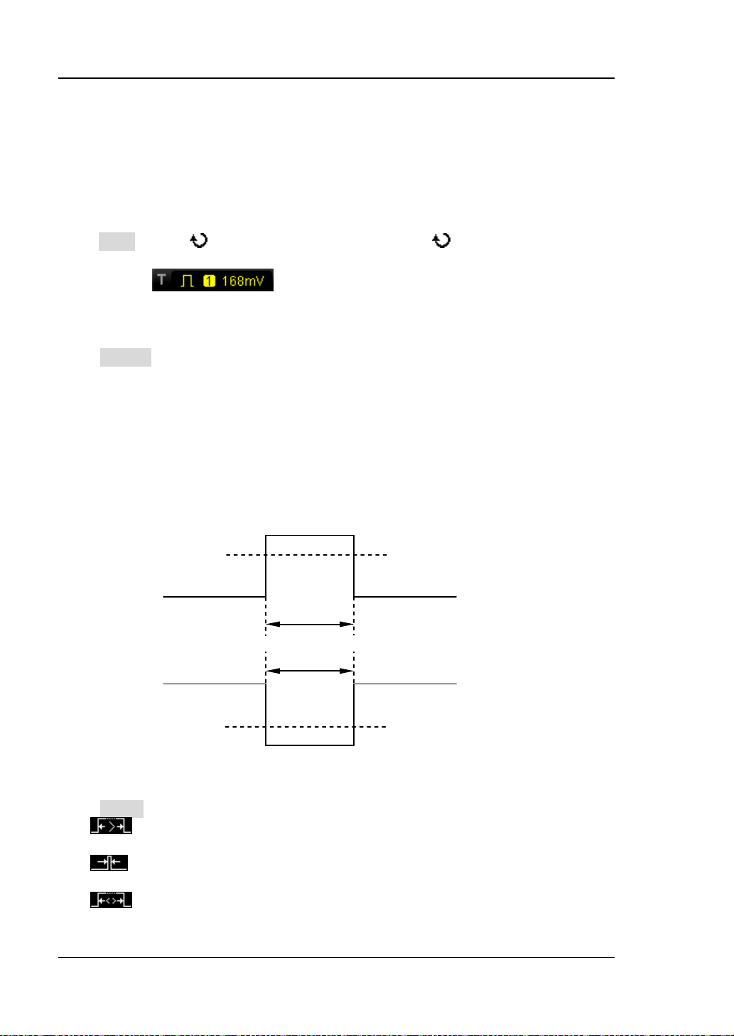
RIGOL Chapter 5 To Trigger the Oscilloscope
Positive
Trigger level
Trigger level
Negitive
A B A
B
Pulse Trigger
Trigger on the positive or negative pulse with a specified width. In this mode, the
oscilloscope will trigger when the pulse width of the input signal satisfies the
specified pulse width condition.
Trigger Type:
Press Type, rotate to select "Pulse" and press down . At this point, the trigger
setting information is displayed at the upper right corner of the screen.
For example,
. The trigger ty pe is pulse trigge r; the t rigger sou rce
is CH1; the trigger level is 168 mV.
Source Selection:
Press Source to open the signal source list and select CH1-CH4 or D0-D15. For the
details, please refer to the introduction in "
Trigger Source". The current trigger
source is displayed at the upper right corner of the screen.
Note: Select channel with signal input as trigger source to obtain stable trigger.
Pulse Condition:
In this oscilloscope, positive pulse width is defin ed as the time difference between
the two crossing points of the trigger lev el and positive pulse; negative pulse width is
defined as the time difference between the two crossing points of the trigger level
and negative pulse, as shown in the figure below.
pulse width
pulse width
Press When to select the desired pulse width condition.
: trigger when the positive pulse width of the input signal is greater than
5-8 MSO1000Z/DS1000Z User’s Guide
Figure 5-3 Positive Pulse Width/Negative Pulse Width
the specified pulse width.
: trigger when the positive pulse wi dth of the input si gnal is lower than the
specified pulse width.
: trigger when the positive pulse width of the input signal is greater than
the specified lower limit of pulse width and lower than the specified upper limit
Page 83

Chapter 5 To Trigger the Oscilloscope RIGOL
of pulse width.
: trigger when the negativ e pulse width of the input signal is great er tha n
the specified pulse width.
: trigger when the negative pulse width of the input signal is lower than
the specified pulse width.
: trigger when the negativ e pulse width of the input signal is greater tha n
the specified lower limit of pulse width and lower than the specified upper limit
of pulse width.
Pulse Width Setting:
When the Pulse Condition is set to
, , or , press
Setting and use to input the desired value. The range a vailable is from 8 ns
to 10 s.
When the Pulse Condition is set to or , press Upper Limit and
Lower Limit and use to input the desired values respectively. The range of
the upper limit is f rom 16 ns to 10 s. The range of the lower limit is fro m 8 ns to
9.99 s.
Note: The lower limit of the pulse width must be lower than the upper limit.
Trigger Mode:
Press Sweep t o open t he trigger mo de list and select auto , nor mal or single . F or the
details, please refer to "
Trigger Mode". The corresponding status light of the
current trigger mode turns on.
Trigger Setting:
Press Setting to set the trigger parameters (trigger holdoff and noise rejection)
under this trigger type.
Trigger Level:
When the trigger source is an analog channel, you can use TRIGGER LEVEL to
modify the level. For the d etails, please ref er to the introdu ction of "
Trigger Level".
MSO1000Z/DS1000Z User’s Guide 5-9
Page 84
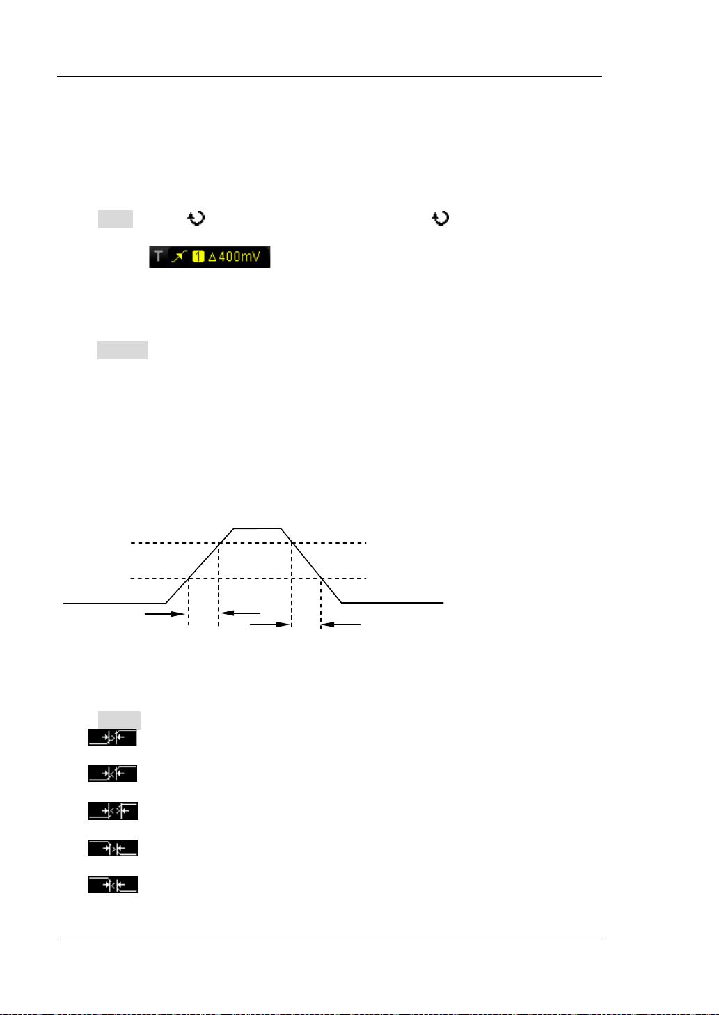
RIGOL Chapter 5 To Trigger the Oscilloscope
A
The upper limit of trigger level (Up Level)
Slope Trigger
In slope trigger, the oscilloscope triggers on the positive or negative slope of the
specif ied time. This trigger mode is applicable to ramp and triangle waveforms.
Trigger Type:
Press Type, rotate to select "Slope" and press down . At this point, the
trigger setting information is displayed at the upper right corner of the screen.
For example,
. The trigger type is slope trigger; the trigger source
is CH1; the difference between the upper limit of trigger level and the lower limit of
trigger level is 400 mV.
Source Selection:
Press Source to switch the signal source and select CH1-CH4. For the details, please
refer to the introduction in "
Trigger Source". The current trigger source is
displayed at the upper right corner of the screen.
Note: Select channel with signal input as trigger source to obtain stable trigger.
Slope Condition:
In this oscilloscope, positive slope time is defined as the time difference between the
two crossing points of trigger level line A and B with the rising edge; negative slope
time is defined as the time difference between the two crossing points of trigger level
line A and B with the falling edge as shown in the figure below.
B
The lower limit of trigger level (Low Level)
Positive
Slope Time
Negative
Slope Time
Figure 5-4 Positive Slope Time/Negative Slope Time
Press When to select the desired slope condition.
: trigger when the positive slope time of the input signal is greater than
the specified time.
: trigger when the positive slope time of the i nput signal is l ower than the
specif ied time.
: trigger when the positive slope time of the input signal is greater than
the specified lower limit of time and lower than the specified upper limit of time.
: trigger when the ne gativ e slope time of the inp ut si gnal is greater than
the specified time.
: trigger when the negative slope time of the input signal is lower than
the specified time.
5-10 MSO1000Z/DS100 0Z U s e r’s Guide
Page 85

Chapter 5 To Trigger the Oscilloscope RIGOL
UpLevel - LowLevel
SlewRate=
Time
UpLevel - LowLevel UpLevel - LowLevel
SlewRate= ~
UpperLimit LowerLimit
: trigger when the negative slope t ime of the input signal is greate r than
the specified lower limit of time and lower than the s pecified upper limit of time.
Time Setting:
When the Slope Condition is set to
, , or ,
press Time and use to input the desired value. The range a vailable is from 8
ns to 10 s.
When the Slope Condition is set to or , press Upper Limit
and Lower Limit and use to input the desired values respectively. The
range of time upper limit i s from 16 ns to 10 s . The r ange of the t ime lower li mit
is from 8 ns to 9.99 s.
Note: The time lower limit must be lower than the upper limit.
Vertical Window and Trigger Level:
After the trigger condition setting is completed, adjust the trigger level using
TRIGGER
LEVEL to correctly trigger the signal and obtain stable waveform. The
adjustment mode of the trigger level is different when different vertical window is
selected in slope trigg er. Press Vertical and use to sel ect the desired vertical
window or press down Vertical continuously to swi tch the vertical window. You can
choose to only adjust the upper limit, the lower limit or both of them.
: only adjust the upper limit of the trigger level. During the adjustment,
"UP Level" and "Slew Rate" change accordingly but "Low Level" remains
unchanged.
: only adjust the lower limit of th e trigg er level. During the adjustment,
"Low Level" and "Slew Rate" change accordingly but "UP Level" remains
unchanged.
: adjus t the upper and lower limits of the trigger level at the same time.
During the adjustment, "UP Level" and "Low Level" change accordingly but
"Slew Rate" remains unchanged.
When the Slope Condition is set to
, , , or , the
current trigger level and slew rate will be displayed at the lower left corner of the
screen, as shown in figure 5-5 (a). The formula of slew rate is:
When the Slope Condition is set to or , the current trigger level
and slew rate range will be displayed at t he low er left corner o f the s creen, as shown
in figure 5-5 (b). The formul a of sl ew rate range is:
MSO1000Z/DS1000Z User’s Guide 5-11
(5-1)
(5-2)
Page 86

RIGOL Chapter 5 To Trigger the Oscilloscope
(a) (b)
Figure 5-5 Trigger Level Information Display
Note: Under the "Slope" trigger menu, you can also press down the trigger level
knob continuously to switch the vertical window.
During the adjustment of trigger level, two o r a nge trigger level lines an d t wo t ri gge r
marks (
and ) appear on the screen and move up and down with the rotation
of the knob. At the same time, the current trigger level information is displayed at the
lower right corner of the s c reen according to different sl o pe co nditio n se ttings. After
stopping turning the knob, the trigger level lines and trigger level information
disappear in about 2 s.
Trigger Mode:
Press Sweep t o open t he trigger mo de list and select auto , nor mal or single . F or the
details, please refer to "
Trigger Mode". The corresponding status light of the
current trigger mode turns on.
Trigger Setting:
Press Setting to set the trigger parameters (trigger holdoff and noise rejection)
under this trigger type.
5-12 MSO1000Z/DS100 0Z U s e r’s Guide
Page 87
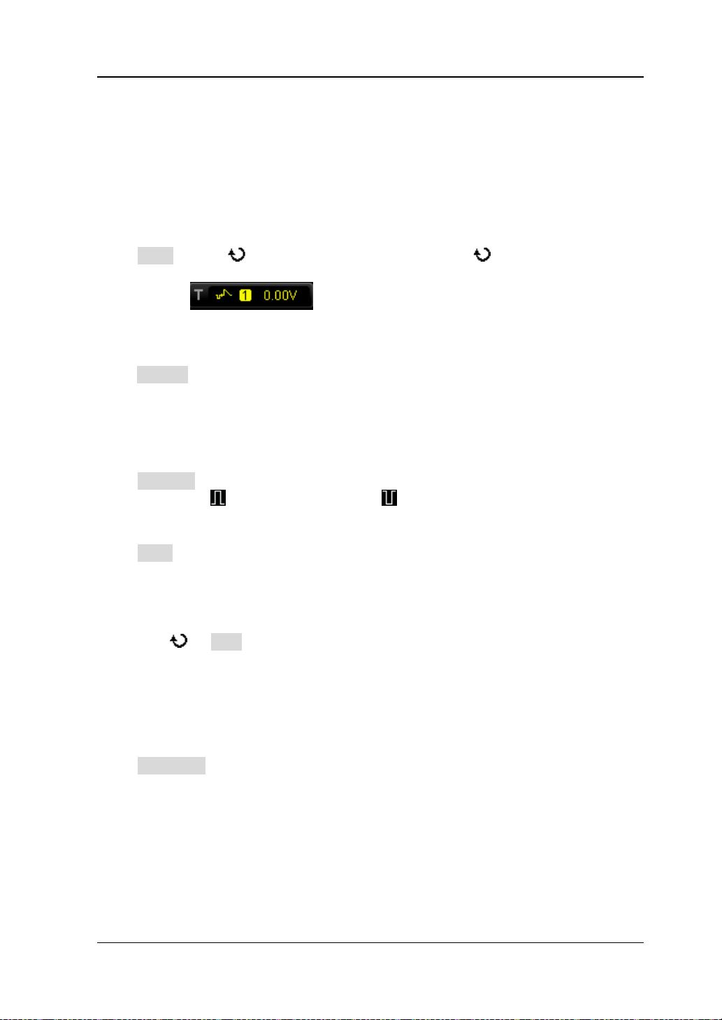
Chapter 5 To Trigger the Oscilloscope RIGOL
Video Trigger
The video signal can include ima ge information and timing information and can
adopt diff e re n t standards and formats. MSO1000Z/DS1000Z can trigg e r on the
standard video signal field or line of NTSC (National T el evision Standards Com mittee),
PAL (Phase Alternating Line) or SECAM (Sequential Couleur A Memoire).
Trigger Type:
Press Type, rotate to select "Video" and press down . At this point, the
trigger setting information is displayed at the upper right corner of the screen.
For ex ampl e,
source is CH1; the trigger level is 0.00 V.
Source Selection:
Press Source to switch the signal source and select CH1-CH4. For the details, please
refer to the introduction in "
displayed at the upper right corner of the screen.
Note: Select channel with signal input as trigger source to obtain stable trigger.
Video Polarity:
Press Polarity to select the desired video polarity. The polarities available are
positive polarity (
Sync:
Press Sync to select the desired sync type.
All Line: trigger on the first line found.
Line: for NTSC and PAL/SECAM video standards, trigger on the specified line in
the odd or even field.
Note: When this s ync t rigger m ode is sele cted, you can modify the li ne numbe r
using in Line menu w ith a step of 1.
The range of the line number is from 1 to 525 (NTSC), 1 to 625 (PAL/SECAM), 1
to 525 (480P) or 1 to 625 (576P).
Odd: trigger on the rising edge of the first ramp pulse in the odd field.
Even: trigger on the rising edge of the first ramp pulse in the even field.
Video Standard:
Press Standard to select the desired video standard.
NTSC: the field frequency is 60 fields per second a nd the frame freque nc y is 30
frames per second. The TV scan line is 525 with the even field goes first and the
odd field follows behind.
PAL/SECAM:
--PAL: the frame frequency is 25 frames per second. The TV scan line is 625 with
the odd field goes first and the even field follows behind.
--SECAM: the frame frequency is 25 frames per second. The TV scan li ne i s 625
with interlaced scan.
) and negative polarity ( ).
. The trigger type is video trigger; the trigger
Trigger Source". The current trigger source is
MSO1000Z/DS1000Z User’s Guide 5-13
Page 88
RIGOL Chapter 5 To Trigger the Oscilloscope
Tips
users can quickly judge the signal quality and discover abnormalities.
480P: the frame frequency is 60 frames per second; the TV scan line is 525;
progressive scan; the line frequency is 31.5 kHz.
576P: the frame frequency is 60 frames per second; the TV scan line is 625;
progressive scan.
Trigger Mode:
Press Sweep t o open t he trigger mo de list and select auto , nor mal or single . F or the
details, please refer to "
Trigger Mode". The corresponding status light of the
current trigger mode turns on.
Trigger Setting:
Press Setting to set the trigger parameter (noise rejection) under this trigger type.
Trigger Level:
Use TRIGGER LEVEL to modify the level. For the details, please refer to the
introduction o f "
Trigger Level".
For a better observation of the waveform details in the video signal, you can
set a larger memory depth f irst.
In the trigger debugging process of video signals, the frequency in different
part of the signal can be reflected by different brightness as RIGOL digital
oscilloscope provide s t he intensity graded c olor disp lay function. Experienced
5-14 MSO1000Z/DS100 0Z U s e r’s Guide
Page 89

Chapter 5 To Trigger the Oscilloscope RIGOL
…
L
H
(CH1-CH4 or D0-D15)
…
(CH1-CH4 or D0-D15)
Pattern Trigger
Identify a tri gger condition by lookin g for a specified pattern. This pattern is a l ogical
"AND" combination of channels. Each channel can have a value of high (H), low (L)
or don't care (X) . A risin g or falling edge (you can o nly specify a single edge) can be
specified for one channel included in the pattern. When an edge is specified, the
oscilloscope will trigger at the edge specified if the pattern set for the other channels
are true (namely the actual pattern of the channel is the same with the preset
pattern). If no edge is specified, the oscilloscope will trigger on the last edge that
makes the pattern true. If all the channels in the pattern a re set t o "Don’t Care", the
oscilloscope will not trigger.
Figure 5-6 Pattern Trigger
Trigger Type:
Press Type, rotate to select "Pattern" and press down . At this point, the
trigger setting information is displayed at the upper right corner of the screen.
For example, . The trigger type is pattern trigger; the current
trigger source is CH1; the trigger level is 0.00 V.
Source Selection:
Press Source to open the signal source list and select CH1-CH4 or D0-D15. For the
details, please refer to the introduction in "
source is displayed at the upper right corner of the screen.
Pattern Setting:
Press Code to set the pattern of the current signal source. At this point, the
corresponding pattern is displayed at the bottom of the screen. The patterns of
channels CH1-CH4 and D0-D15 are presented from left to right as shown in the
figure below.
MSO1000Z/DS1000Z User’s Guide 5-15
Trigger Source". The current trigger
: set the pattern of the channel selected to "H", namely the voltage level is
higher than the trigger level of the channel.
: set the pattern of the channel selected to "L", namely the voltage level is
lower than the trigger level of the channel.
: set the pattern of the channel selected to "Don’t Care", namely this channel
is not used as a part of the pattern. When all channels in the pattern are set to
Page 90

RIGOL Chapter 5 To Trigger the Oscilloscope
"Don’t Care", the oscilloscope will not trigger.
or : set the pattern to the risin g or fal ling edge of the channel selected.
Note:
When digital channels D7-D0 are enabled, CH4 is automatically disabled; the
corresponding pattern cannot be set and is replaced by X. When D15-D8 a re
enabled, CH3 is automatically disabled; the correspo nding pat tern cann ot be set
and is replaced by X.
Only one edge (rising or falling edge) can be specified in the pattern. If one
edge item is currently defined and t hen another edge item is defined in another
channel in the pattern, the former edge item defined will be replaced by X.
All Bits:
Press AllBits t o set the patte rns of all tri gger sou rces to the pattern settings selected
currently.
Trigger Mode:
Press Sweep t o open t he trigger mo de list and select auto , nor mal or single . F or the
details, please refer to "
Trigger Mode". The corresponding status light of the
current trigger mode turns on.
Trigger Setting:
Press Setting to set the trigger parameters (trigger holdoff and noise rejection)
under this trigger type.
Trigger Level:
For the analog channels, the trigger level of each channel needs to be set
independently. For exampl e, set the trigger level of CH1. Press Source to select CH1,
and then use TRIGGER
to the introduction of "
LEVEL to modify the level. For the details, please refer
Trigger Level".
5-16 MSO1000Z/DS100 0Z U s e r’s Guide
Page 91

Chapter 5 To Trigger the Oscilloscope RIGOL
Duration Trigge r
In duration trigger, the instrument identifies a trigger condition by looking for the
duration of a specified pattern. This pattern is a logical "AND" combination of the
channels. Each channel can have a value of high (H), low (L) or don’t care (X). The
instrument triggers when the duration (△T) of this pattern meets the preset time, as
shown in the figure below.
Figure 5-7 Duration Trigger
Trigger Type:
Press Type, rotate to select "Duration" and press down . At this point, the
trigger setting information is displayed at the upper right corner of the screen.
For example,
trigger source is CH1; the trigger level is 0.00 V.
Source Selection:
Press Source to open the signal source list and select CH1-CH4 or D0-D15. For the
details, please refer to the introduction in "
source is displayed at the upper right corner of the screen.
Pattern Setting:
Press Code to set the pattern of the current channel. At this point, the pattern
setting area (as sh own in the figure below) is displayed at t he bottom of the s c reen.
: set the pattern of the channel selected to "H", namely the voltage level is
higher than the trigger level of the channel.
: set the pattern of the channel selected to "L", namely the voltage level is
. The trigger type is duration trigger; the current
Trigger Source". The current trigger
MSO1000Z/DS1000Z User’s Guide 5-17
Page 92

RIGOL Chapter 5 To Trigger the Oscilloscope
lower than the trigger level of the channel.
: set the pattern of the channel selected to "Don’t Care", namely this channel
is not used as a part of the pattern. When all channels in the pattern are set to
"Don’t Care", the oscilloscope will not trigger.
Note: When digital channels D7-D0 are enabled, CH4 is automatically disabled; its
correspondin g pattern can not be set and is replaced by X. When D15-D8 are enabled,
CH3 is automatically disabled; its corresponding pattern cannot be set and is
replaced by X.
All Bits:
Press AllBits to set the pa tterns of a ll trigge r source s to the pattern settings selected
currently.
Trigger Condition:
Press When to select the desired trigger condition.
>: trigger when the duration of the pattern is greater than the preset time.
Press Time to set the duration of the pattern and the range is from 8 ns to 10 s.
<: trigger when the duration of the pattern is lower than the preset time. Press
Time to set the duration of the pattern and the range is from 8 n s t o 1 0 s.
<>: trigger when the dur ation of the pattern is l ower than the u pper limit of the
preset time and greater than the lower limit of the preset time. Press Upper
Limit to se t t he upper limit of the du r at ion of the pattern and the r a nge is from
16 ns to 10 s. Press Lower Limit to set the lower limit of the duration of the
pattern and the range is from 8 ns to 9.99 s.
Note: The time lower limit must be lower than the time upper limit.
Trigger Mode:
Press Sweep t o open t he trigger mo de list and select auto , nor mal or single . F or the
details, please refer to "
Trigger Mode". The corresponding status light of the
current trigger mode turns on.
Trigger Setting:
Press Setting to set the trigger parameters (trigger holdoff and noise rejection)
under this trigger type.
Trigger Level:
Press Source to select CH1 to CH4 respectively; use TRIGGER LEVEL to modify
the trigger level for each channel. For the details, please refer to the introduction of
Trigger Level".
"
5-18 MSO1000Z/DS100 0Z U s e r’s Guide
Page 93
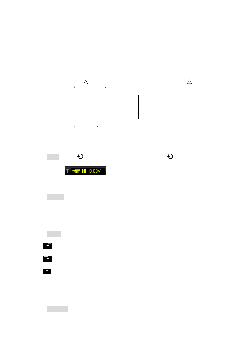
Chapter 5 To Trigger the Oscilloscope RIGOL
Time Out
T
Time Out< T
TimeOut Trigger (Optional)
In timeout trigger, the instrument triggers when the time interval (△T) from when
the rising edge (or falling edge) of t he input signal passes thro ugh the trigger level to
when the neighbouring falling edge (or rising edge) passes through the trigger level
is greater than the timeout time set, as shown in the f ig ure below.
Figure 5-8 TimeOut Trigger
Trigger Type:
Press Type, rotate to select "TimeOut" and press down . At this point, the
trigger setting information is displaye d at the upper right corner of the screen.
For example,
source is CH1; the trigger level is 0.00 V.
Source Selection:
Press Source to open the signal source list and select CH1-CH4 or D0-D15. For the
details, please refer to the introduction in "
source is displayed at the upper right corner of the screen.
Note: Select channel with signal input as trigger source to obtain stable trigger.
Edge Type:
Press Slope to select the type of the f ir st edge of the input signal that passes
through the trigger level.
: start timing when the rising edge of the input signal passes through the
trigger level.
Timeout Time:
Timeout time represents the minimum time that the clock signal must be in the idle
state before the oscilloscope starts searching for the data meets the trigger con dition.
Press TimeOut to set the timeout time of timeout trigger and the range is from 16
: start timing when the falling edge of the input signal passes through the
trigger level.
: start timing when any edge of the input signal passes through the trigger
level.
. The trigger type is timeout trigger; the trigger
Trigger Source". The current trigger
MSO1000Z/DS1000Z User’s Guide 5-19
Page 94

RIGOL Chapter 5 To Trigger the Oscilloscope
ns to 10 s.
Trigger Mode:
Press Sweep t o open t he trigger mo de list and select auto , nor mal or single . F or the
details, please refer to "
Trigger Mode". The corresponding status light of the
current trigger mode turns on.
Trigger Setting:
Press Setting to set the trigger parameter (noise rejection) under this trigger type.
Trigger Level:
When the trigger source is an analog channel, you can use TRIGGER LEVEL to
modify the level. For the details, plea se refe r to the i ntro ducti on of "
Trigger Level".
5-20 MSO1000Z/DS100 0Z U s e r’s Guide
Page 95
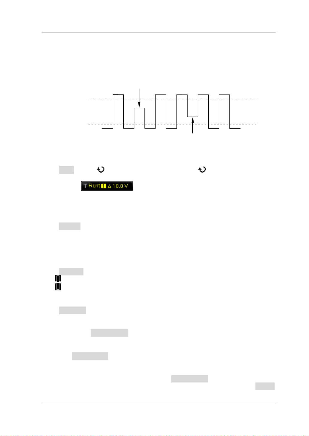
Chapter 5 To Trigger the Oscilloscope RIGOL
Upper Limit of the
Lower Limit of the
Positive Runt Pulse
Negative Runt Pulse
Runt Trigger (Opti onal)
This trigger mode is used to tri gger pulses that p ass through one trigger level but fail
to pass through the other trigger level as shown in the figure below.
Trigger Level
Trigger Level
Figure 5-9 Runt Trigger
Trigger Type:
Press Type, rotate to select "Runt" and press down . At this point, the trigger
setting information is displayed at the upper right corner of the screen.
For example,
. The trigger type is runt trigger; the trigger source
is CH1; the difference between the upper limit of trigger level and the lower limit of
trigger level is 10.00 V.
Source Selection:
Press Source to switch the signal source and select CH1-CH4. For the details, please
refer to the introduction in "
Trigger Source". The current trigger source is
displayed at the upper right corner of the screen.
Note: Select channel with signal input as trigger source to obtain stable trigger.
Pulse Polarity:
Press Polarity to select the pulse polarity of runt trigger.
: positive polarity. The instrument triggers on the positive runt pulse.
: negative polarity. The instrument triggers on the negative runt pulse.
Qualifier:
Press Qualifier to set the trigger conditions of runt trigger.
None: do not set the trigger condition of runt trigger.
>: trigg er when the runt pulse width is greater than the lower limit of pulse
width. Press Lower Limit to set the minimum pulse width of runt trigger. The
range available is from 8.00 ns to 10 s.
<: t rigger when the runt pulse width is lower than th e upper limit of pulse width .
Press Upper Limit to set the maximum pulse width of runt trigger. The range
available is from 16.0 n s to 10.0 s.
<>: trigger when the run t pulse width is greater than t he lower limit and lower
than the upper limit of pulse width. Press Upper Limit to set the maximum
pulse width of runt trigger and the ran ge is from 16.0 ns to 10.0 s; press Lower
MSO1000Z/DS1000Z User’s Guide 5-21
Page 96
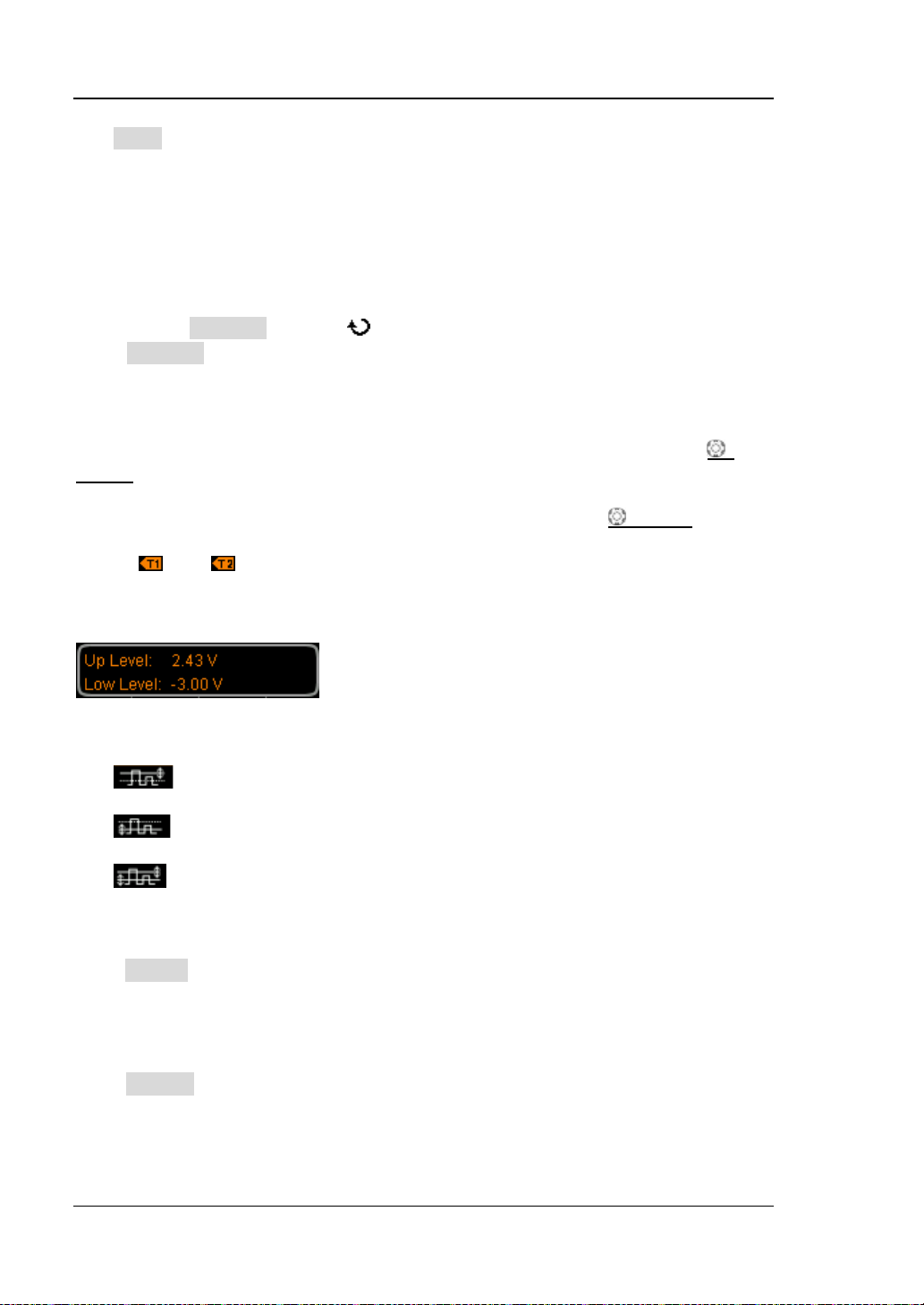
RIGOL Chapter 5 To Trigger the Oscilloscope
Limit to set the minimum pulse wi dth of runt t rigger and t he ran ge is f rom 8.00
ns to 9.99 s.
Note: The lower limit of the pulse width must be lower than the upper limit.
Vertical Window and Trigger Level:
After the trigger condition setting is completed, you need to adjust the trigger level
to correctly trigger the signal and obtain stable waveform. The adjustment mode of
the trigger level is different when different vertical window is selected in the runt
trigger. Press Window and use to select the desired vertical window or press
down Window continuously to switch the vertical window. You can choose to only
adjust the upper limit, t he lower limit or both of t hem. For more deta ils, please refer
to the following introduction.
Note: Under the "Runt" trigger menu, you can also press down TRIGGER
LEVEL continuously to switch the vertical window.
After the vertical wind ow type is selected, you can use Trigger LEVEL to adjust
the trigger level. During the adjustment, two orange trigger level lines and trigger
marks (
and ) appear on the screen and move up and down with the rotation
of the knob. At the same time, the current trigger level values are displayed at the
lower left corner of the screen (as shown in the figure below). The tri gger lev el li nes
and trigger marks disappear after you stop rotating the knob for abou t 2 s.
The adjustment mode of the trigger level differs when different vertical window is
selected.
: only adjust the upper limit of the trigger level. During the adjustment,
the "Up Level" changes accordingly and "Low Level" remains unchanged.
: only adjust the lower limit of the trigger level. During the adjustment,
the "Low Level" changes accordingly and the "Up Level" remains unchanged.
: adjust the upper and lower limits of the trigger level at the same time.
During the adjustment, the "Up Level" and "Low Level" change accordingly.
Trigger Mode:
Press Sweep t o open t he trigger mo de list and select auto , nor mal or single . F or the
details, please refer to "
Trigger Mode". The corresponding status light of the
current trigger mode turns on.
Trigger Setting:
Press Setting to set the trigger parameters (trigger holdoff and noise rejection)
under this trigger type.
5-22 MSO1000Z/DS100 0Z U s e r’s Guide
Page 97

Chapter 5 To Trigger the Oscilloscope RIGOL
Window Trigger ( Optio n al)
Window trigger provides a high trigger level and a low trigger level. The instrument
triggers when the input signal passe s through t he high tri gger level or the l ow trigger
level.
Trigger Type:
Press Type, rotate to select "Window" and press down . At this point, the
trigger setting information is displayed at the upper right corner of the screen.
For ex ampl e,
source is CH1; the difference between the upper limit of trigger level and the lower
limit of trigger level is 2.00 V.
Source Selection:
Press Source to switch the trigger source and select CH1-CH4. For the details,
please refer to the introduction in "
displayed at the upper right corner of the screen.
Note: Select channel with signal input as trigger source to obtain stable trigger.
Window Type:
Press WndType to select the kind of edge of the input signal on which the
oscilloscope triggers.
: trigger on the ris i ng edge of the input signal when the voltage level is
greater than the preset high trigger level.
Trigger Position:
After selecting the window t ype, press Position to further specify the time point of
trigger by selecting the trigger position.
Enter: trigger when the trigger signal enters the specified trigger level range.
Exit: trigger when the input signal exits the specified trigger level range.
Time: trigger when the accumulated hold time after the trigger signal enters
Vertical Window and Trigger Level:
Press Window to select the desired vertical window type and use Trigger
LEVEL to adjust the trigger level. For detailed operation, please refer to the
introduction in "
: trigger on the falling edge of the input signal when the voltage level is
lower than the preset low trigger level.
: trigger on any edge of the input signal when the voltage level meets the
preset trigger level.
the specified trigger level range is equal to the window time. When this type is
selected, press Time to set the window time. The range is from 8 ns to 10 s. For
the setting method, please refer to the introduction in "
Method".
Vertical Window and Trigger Level" in runt trigger.
. The trigger type is window trigger; the trigger
Trigger Source". The current trigger source is
Parameter Setting
MSO1000Z/DS1000Z User’s Guide 5-23
Page 98

RIGOL Chapter 5 To Trigger the Oscilloscope
Trigger Mode:
Press Sweep t o open t he trigger mo de list and select auto , nor mal or single . F or the
details, please refer to "
Trigger Mode". The corresponding status light of the
current trigger mode turns on.
Trigger Setting:
Press Setting to set the trigger parameters (trigger holdoff and noise rejection)
under this trigger type.
5-24 MSO1000Z/DS100 0Z U s e r’s Guide
Page 99
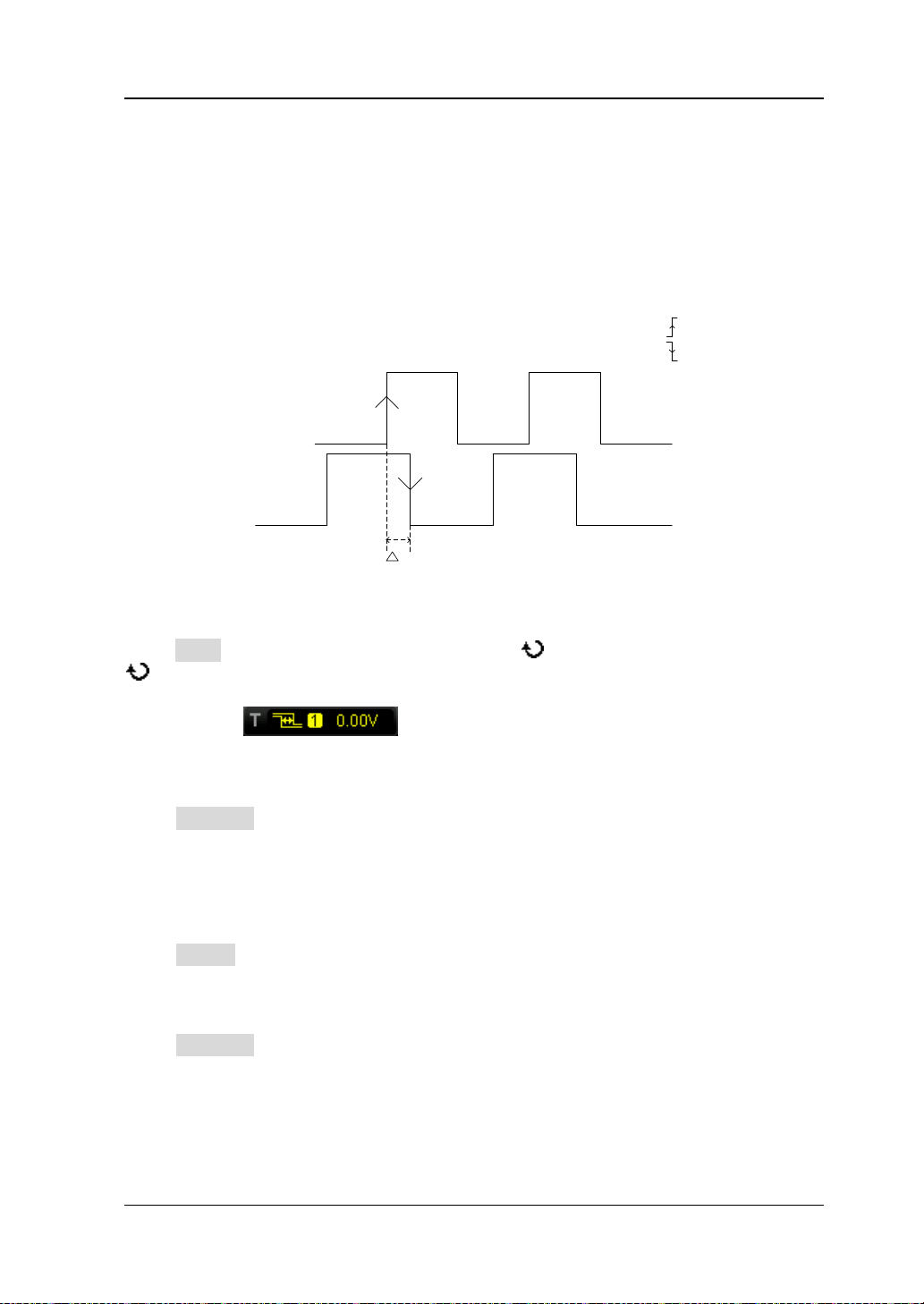
Chapter 5 To Trigger the Oscilloscope RIGOL
T
Source A
Source B
Edge A=
Edge B=
Delay Trigger (Optional)
In delay trigger, you need to set sig nal source A an d signal source B . The oscilloscope
triggers when the time difference (△T) between the specified edges of source A
(Edge A) and source B (Edge B) meets the preset time limit, as shown in the f ig ure
below.
Note: Edge A and Edge B must be neighbouring edges.
Figure 5-10 Delay Trigger
Trigger Type:
Press Type to open the trigger type list. Rotate to select "Delay" and press down
. At this point, the t rigger set ting information is dis played at the upper right corner
of the screen.
For ex ampl e,
. The trigger type is delay trigger; the current
trigger source is CH1; the trigger level is 0.00 V.
Source A:
Press SourceA to select CH1-CH4 as the trigger source of signal source A. For the
details, please refer to the introduction in "
Trigger Source". The current trigger
source is displayed at the upper right corner of the screen.
Note: Select channel with signal input as trigger source to obtain stable trigger.
Edge A:
Press EdgeA to sel ect t he tri gger edge t ype of sign al sou rce A i n dela y t rigger. It can
be set to the rising edge or falling edge.
Source B:
Press SourceB to select CH1-CH4 as the trigger source of signal source B. For the
details, please refer to the introduction in "
source is displayed at the upper right corner of the screen.
Trigger Source". The current trigger
Note: Select channel with signal input as trigger source to obtain stable trigger.
MSO1000Z/DS1000Z User’s Guide 5-25
Page 100

RIGOL Chapter 5 To Trigger the Oscilloscope
Edge B:
Press EdgeB to select the trigger edge t ype of signal s ource B in delay t rigger. It can
be set to the rising edge or falling edge.
Delay Type:
Press DelayType to set the time limit condition of delay trigger.
>: trigger when the time differen ce (△T) between the specified edges of source
A and source B is greater than the preset time lower limit. Press Lower Limit to
set the delay time lower limit in delay trigger and the range is from 8.00 ns to 10
s. For the setting method, please refer to the introduction in "
Parameter
Setting Meth o d ".
<: trigger when the time differen ce (△T) between the specified edges of source
A and source B is lower than the preset time upper limit. Press Upper Limit to
set the delay time upper limit in delay trigger and the range is from 16.0 ns to
10.0 s. For the setting method, please refer to the introduction in "
Parameter
Setting Meth o d ".
<>: trigger when the time difference (△T) between the specified edges of
source A and source B is greater than the lower limit of the preset time and
lower than the upper limit of the preset time. Press Upper Limit to set the
upper limit of the delay time in delay trigger and the range is from 16.0 ns to
10.0 s. Press Lower Limit to set the lower limit of the delay time in delay
trigger and the range is from 8.00 ns to 9.99 s. For the setting method, please
refer to the introduction in "
Paramete r Se t ting Method".
Note: The time lower limit must be lower than the time upper limit.
><: trigger when the time difference (△T) between the specified edges of
source A an d sou r ce B is l owe r t han t he l ow er limi t of th e p res et t ime o r gre at e r
than the upper limit of the preset time. Press Upper Limit to set the upper limit
of the delay time in delay trigger and the range is from 16.0 ns to 10.0 s. Press
Lower Limit to set the lower limit of the delay time in delay trigger and the
range is from 8.00 ns to 9.99 s. For the setting method, please refer to the
introduction in "
Parameter Setting Method".
Note: The time lower limit must be lower than the time upper limit.
Trigger Mode:
Press Sweep t o open t he trigger mo de list and select auto , nor mal or single. For the
details, please refer to "
Trigger Mode". The corresponding status light of the
current trigger mode turns on.
Trigger Setting:
Press Setting to set the trigger parameters (trigger holdoff and noise rejection)
under this trigger type.
Trigger Level:
The trigger level of each source needs to be set independently. For example, set the
trigger level of s ource A. Press SourceA to select the desired source, and then use
5-26 MSO1000Z/DS100 0Z U s e r’s Guide
 Loading...