

Page 1

RIGOL
User’s Guide
DS1000Z Series Digital
Oscilloscope
Jan. 2014
RIGOL Technologies, Inc.
Page 2

Page 3

RIGOL
I
Guaranty and Declaration
Copyright
© 2013 RIGOL Technologies, Inc. All Rights Reserved.
Trademark Information
RIGOL is a registered trademark of RIGOL Technologies, Inc.
Publication Number
UGA17102-1112
Notices
RIGOL products are protected by patent law in and outside of P.R.C.
RIGOL reserves the right to modify or change parts of or all the specifications
and pricing policies at company’s sole decision.
Information in this publication replaces all previously corresponding material.
RIGOL shall not be liable for losses caused by either inci dental or conse quential
in connection with the fu r nis hing , use or perfo rman ce of this manual as well as
any information contained.
Any part of this document is forbidden to be copied or photocopied or
rearranged without prior written approval of RIGOL.
Product Certification
RIGOL guar antees this pr oduct confo rms to the national and industrial stan dar ds in
China as well as the ISO9001:2008 standard and the ISO14001:2004 standard.
Other international standard conformance certif ication is in progress.
Contact Us
If you have any problem or requirement when using o ur products or this manual,
please contact RIGOL.
E-mail: service@rigol.com
Websites: www.rigol.com
DS1000Z User’s Guide
Page 4

RIGOL
II
Safety Requirement
General Safety Summary
Please review the following safety precautions carefully before putting the
instrument into operation so as to avoid any personal injury or damage t o t he
instrument and any product connecte d to it. To prevent potential haza rds, please use
the instrument only specified by this manual.
Use Proper Power Cord.
Only the power cord designed for the instrument and authorized for use within the
local country could be used.
Ground The Instrument.
The instrument is grounded through the Protective Earth lead of the power cord. To
avoid electric shock, it is e ssential t o connect the ea rth terminal of power cord to the
Protective Earth terminal before any inputs or outputs.
Connect the Probe Correctly.
If a probe is used, do not connect the ground lead to high vol t age since it has the
isobaric electric potential as ground.
Observe All Terminal Ratings.
To avoid fire or shock hazard, observe all rat in gs an d mark ers on the instrume nt and
check your manual for more information about ratings before connecting.
Use Proper Overvoltage Protection.
Make sure that no overvoltage (such as that caused by a thunderstorm) can reach
the product, or else the operator might expose to danger of electrical shock.
Do Not Operate Without Covers.
Do not operate the instrument with covers or panels removed.
Do Not Insert Anything into the Holes of Fan.
Do not insert anything into the holes of the fan to avoid damaging the instrument.
DS1000Z User’s Guide
Page 5

RIGOL
III
Use Proper Fuse.
Please use the specified fuses.
Avoid Circuit or Wire Exposure.
Do not touch exposed junctions and components when the unit is powered.
Do Not Operate With Suspected Failures.
If you suspect damage occurs to the instrument, have it inspected by qualified
service personnel before further oper at ions. Any maintenance, adjustment or
replacement especially to circuits or accessories must be performed by RIGOL
authorized personnel.
Keep Well Ventilation.
Inadequate ventilation may cause increasing of temperature or damages to the
device. So please keep well ventilated and inspect the intake and fan regularly.
Do Not Operate in Wet Conditions.
In order to av oid short circuiting t o the interi or of the device or electric shock, please
do not operate in a humid environment.
Do Not Operate in an Explosive Atmosphere.
In order to avoid damages to the device or personal injuries, it is important to
operate the device away from an explosive atmosphere.
Keep Product Surfaces Clean and Dry.
To avoid the influence of dust and/or moisture in air, please keep the surface of
device clean and dry.
Electrostatic Prevention.
Operate in an electrostatic discharge protective area environment to avoid damages
induced by static discharges. Always ground both the internal and external
conductors of the cable to release static before connecting.
Handling Safety.
Please handle with care during transportation to avoid damages to buttons, knob
interfaces and other parts on the panels.
DS1000Z User’s Guide
Page 6
RIGOL
IV
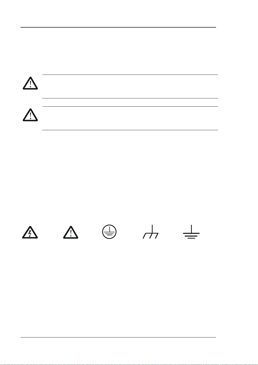
Warning state ments indicate the conditions or practices that could result in
CAUTION
Hazardous
Safety
Protective
Chassis
Test
Safety Terms and Symbols
Terms Used in this Manual. These terms may appear in this manual:
WARNING
injury or loss of life.
Caution statements indicate the c onditions or p ractic es that coul d result in
damage to this product or other property.
Terms Used on the Product. These terms may appear on the Product:
DANGER
WARNING indicates an injury or hazard may be accessible potentially.
CAUTION indicates potential damage to the instrument or other property might
Symbols Used on the Product. These symbols may appear on the product:
indicates an injury or hazard may immediately happen.
occur.
Voltage
Warnning
Earth
Terminal
Ground
Ground
DS1000Z User’s Guide
Page 7

RIGOL
V
Allgemeine Sicherheits Informationen
Überprüfen Sie diefolgenden Sicherheitshinweise
sorgfältigumPersonenschädenoderSchäden am Gerätundan damit verbundenen
weiteren Gerätenzu vermeiden. Zur Vermeidu ng vonGefahren, nutzen Sie bitte das
Gerät nur so, wiein diesem Handbuchangegeben.
Um Feuer oder Verletzungen zu vermeiden, verwenden Sie ein
ordnungsgemäßes Netzkabel.
Verwenden Sie für dieses Gerät nur das für ihr Land zugelass ene u nd genehm igte
Netzkabel.
Erden des Gerätes.
Das Gerät ist durch den Schutzleiter im Netzkabel geerdet. Um Gefahren durch
elektrischen Schlag zu vermeiden , ist es unerlässlich, die Er dung durchzufüh ren. Erst
dann dürfen weitere Ein- oder Aus gä nge verbunden werden.
Anschluss einesTastkopfes.
Die Erdungsklemmen der Sonden sindauf dem gleichen Spannungspegel des
Instruments geerdet. SchließenSie die Erdungsklemmen an keine hohe Spannung
an.
Beachten Sie alle Anschlüsse.
Zur Vermeidung von Feuer oder Stromschlag, beachten Sie alle Bemerkungen und
Markierungen auf dem Instrument. Bef olgen Sie die Bedienun gsanleitung für weitere
Informationen, bevor Sie weitere Anschlüsse an das Instrument legen.
Verwenden Sie einen geeigneten Überspannungsschutz.
Stellen Sie sicher, daß keinerlei Überspannung (wie z.B . du rch Gewitter verursacht)
das Gerät erreichen kann. Andernfallsbestehtfür den Anwender die
GefahreinesStromschlages.
Nicht ohne Abdeckung einschalten.
Betreiben Sie das Gerät nicht mit entfernten Gehäuse-Abdeckungen.
Betreiben Sie das Gerät nicht geöffnet.
Der Betrieb mit offenen oder entfernten Gehäuseteilen ist nicht zulässig. Nichts in
entsprechende Öffnungen stecken (Lüfter z.B.)
Passende Sicherung verwenden.
Setzen Sie nur die spezifikationsgemäßen Sicherungen ein.
Vermeiden Sie ungeschützte Verbindungen.
DS1000Z User’s Guide
Page 8

RIGOL
VI
Berühren Sie keine unisolierten Verbindungen oder Baugrup pen, w ährend das Gerät
in Betrieb ist.
Betreiben Sie das Gerät nic h t im Fehlerfall .
Wenn Sie am Gerät einen Defekt vermuten, sorgen Sie dafür, bevor Sie das Gerät
wieder betreiben, dass eine Untersuchung durch qualifiziertes Kundendienstpersonal
durchgeführt wird.Jedwede Wartung, Einstellarbeiten oder Austausch von Teilen am
Gerät, sowie am Zubehör dürfen nur von RIGOL au t orisiertem Personal
durchgeführt werden.
Belüftung sicherstellen.
Unzureichende Belüftung kann zu Temperaturanstiegen und somit zu thermischen
Schäden am Gerät führen. Stellen Sie deswegen die Belüftung sicher und
kontrollieren regelmäßig Lüfter und Belüftungsöffnungen.
Nicht in feuc h te r Um g ebung betreiben.
Zur Vermeidun g von Kurzschluß im Geräteinne ren und Stromschlag betreiben Sie das
Gerät bitte niemals in feuchter Umgebung.
Nicht in explosiver Atmosphäre betreiben.
Zur Ve rm e idung von Pe rs onen- und Sachschäden ist es unumgänglich, das Gerät
ausschließlich fernab jedweder explosiven At mosphäre zu betreiben.
Geräteoberflächen sauber und trocken halten.
Um den Einfluß von Staub und Feuchtigkeit aus der Luft auszuschließen, halten Sie
bitte die Geräteoberflächen sauber und trocken.
Schutz gegen elektrostatische Entladung (ESD).
Sorgen Sie für eine elektrostatisch geschützte Umgebung, um somit Schäden und
Funktionsstörungen durch ESD zu vermeiden. Erden Sie vor dem Anschluß immer
Innen- und Außenleiter der V erbindungsleitung, um st atische Aufladung zu entladen.
Die richtige Verwendung desAkku.
Wenneine Batterieverwendet wird, vermeiden Sie hohe Temperaturen bzw. Feuer
ausgesetzt werden.Bewahren Sie es außerhalbder Reichweitevon Kindern
auf . UnsachgemäßeÄnderung derBatterie(Anmerkung:Lithium-Batterie)kann zu einer
Explosion führen. VerwendenSie nur von RIGOLangegebenenAkkus.
Sicherer Transport.
Transportieren Sie das Gerät sorgfältig (Verpackung!), um Schäden an
Bedienelementen, Anschlüssen und anderen Teilen zu vermeiden.
DS1000Z User’s Guide
Page 9
RIGOL
VII
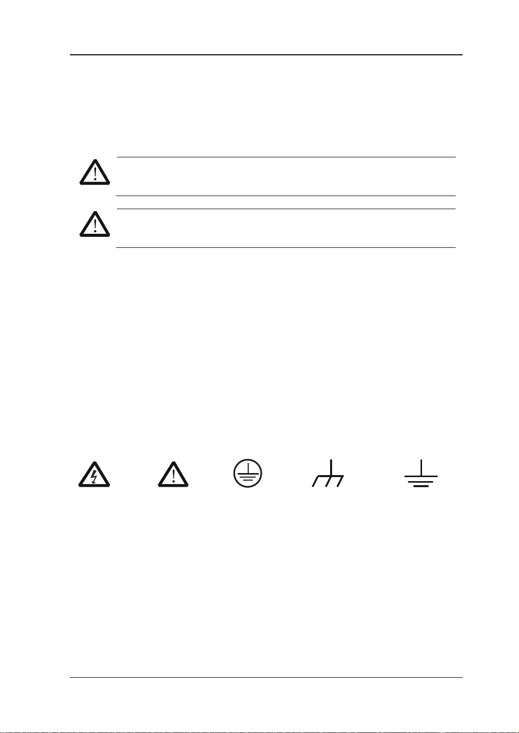
WARNING
Schäden oder den Tod von Personen zur Folge haben können.
CAUTION
Schäden am Gerät hervorrufen können.
DANGER
weist auf eine Verletzung ode r Gefäh r dun g hin, die sof ort
geschehen kann.
WARNING
weist auf eine Verletzung oder Gefährd ung hin, die möglicherweise
nicht sofort geschehen.
CAUTION
bedeutet, dass eine mögliche Beschädigung des Instruments oder
anderer Gegenstände auftreten kann.
Sicherheits Begriffe und Symbole
Begriffe in diesem Guide. Diese Begriffe können in diesem Handbuch
auftauchen:
Die Kennzeichnung WARNING beschreibt Gefahrenquell en die leibliche
Die Kennzeichnung Caution (Vorsicht) beschreibt Gefahrenquellen die
Begriffe auf dem Produkt. Diese Bedingungen können auf dem Produkt
erscheinen:
Symbole auf dem Produkt. Diese Symbole können auf dem Produkt
erscheinen:
GefährlicheS
pannung
SicherheitsHinweis
Schutz-erde Gehäusemasse Erde
DS1000Z User’s Guide
Page 10
RIGOL
VIII
WARNING
Measurement Category
Measurement Category
DS1000Z series digital oscilloscopes can make measurements in Measurement
Category I.
This oscilloscope can only be used for measurements within its specified
measurement categories.
Measurement Category Definitions
Measurement category I is for measurements performed on circuits not directly
connected to MAINS. Examples are measurements on circuits not deriv ed from
MAINS, and specially protected (internal) MAINS derived circuits. In the latter case,
transient stresses are variable; for that reason, the transient withstand capability of
the equipment is made known to the user.
Measurement category II is for measurements performed on circuits directly
connected to the low volta ge install ation. Exa mples a re measure ments o n house hold
appliances, portable tools and similar equipment.
Measurement category III is fo r measure ments perf ormed in the b uilding inst allation.
Examples are measurements on distribution boards, circuit-breakers, wiring,
including cables, bus-bars, junction boxes, switches, socket-outlets in the fixed
installation, and equipment for industrial use and some other equipment, for
example. Stationary motors with permanent connection to the fixed installation.
Measurement category IV is for measurements performed at the source of the
low-voltage installation. Examples are electricity meters and measurements on
primary overcurr e n t prot ec tion devices and ripple control units.
DS1000Z User’s Guide
Page 11
RIGOL
IX
WARNING
Ventilation Requirement
This oscilloscope uses fan to force cooling. Please make sure that the air intake and
exhaust areas are free from obstructions and have free air. When using the
oscilloscope in a bench-top or rack setting, provide at least 10 cm clearance beside,
above and behind the instrument for adequate ventilation.
Inadequate ventilation may cause temperature increase which would
damage the instrument. So please keep the instrument well ventilated
during operation and inspect the intake and fan regularly.
DS1000Z User’s Guide
Page 12
RIGOL
X
o avoid short ci rcuit insid e the instru ment or e lectric s hock, please do n ot
WARNING
reach the product, or else the operator might expose to danger of elect ric
Working Environment
Temperature
Operating: 0℃ to +50℃
Non-operating: -40℃ to +70℃
Humidity
0℃ to +30℃:≤95% relative humidity
+30℃ to +40℃:≤75% relative humidity
+40℃ to +50℃:≤45% relative humility
WARNING
T
operate in humid environment.
Altitude
Operating: less than 3 km
Non-operating: less than 15 km
Installation (overvoltage) Category
This product is powered by mains conforming to installation (overv oltage) category
II.
Make sure that no overvoltage (such as that caused by thunderbolt) can
shock.
Installation (overvoltage) Cate g ory Definitions
Installation (overvoltage) category I refers to signal level which is applicable to
equipment measurement terminals connected to the source circuit. In these
terminals, precautions are done to limit the transient voltage to the corresponding
low level.
Installation (overvoltage) category II refers to the local power distribution level
which is applicable to equipment connected to the AC line (AC power).
DS1000Z User’s Guide
Page 13

RIGOL
XI
Pollution Degree
Degree 2
Pollution Degree Definitions
Pollution degree 1: No pollution or only dry, non-conductive pollution occurs. The
pollution has no influence. For example: a clean room or air-conditioned office
environment.
Pollution degree 2: Normally only dry, non-conductive pollution occurs. Occasionally
a temporary conductivity caused by condensation may occur. For example: general
indoor environment.
Pollution degree 3: Conductive pollution occurs, or dry, non-conductive pollution
occurs which becomes conductive due to condensation which is expected. For
example: sheltered outdoor environment.
Pollution degree 4: Pollution that generates persistent conductivity through
conductive dust, rain, or snow. For example: outdoor locations.
Safety Class
Class 1 – Grounded Product
DS1000Z User’s Guide
Page 14
RIGOL
XII
General Care and Cleaning
General Care:
Do not store or leave the instrument in where the instrument will be exposed to
direct sunlight for long periods of time.
Cleaning:
Clean the instrument regularly according to its operating conditions. To clean the
exterior surface, perform the following steps:
1. Disconnect the instrument from all power sources.
2. Clean the loose dust on the outside of the instrument with a lint - free cloth (with
mild detergent or water). When cleaning t he LCD, tak e care to avoid scarifying
it.
CAUTION
To avoid damages to the instrument, do not expose them to liquids which
have causticity.
WARNING
To avoid injury resulting from short circuit, make sure the instrument is
completely dry before reconnecting it to a pow e r s ou r ce.
DS1000Z User’s Guide
Page 15

RIGOL
XIII
Environmental Considerations
The following symbol indicates that this product complies with the WEEE Directives
2002/96/EC.
Product End-of-Life Handling
The equipment may contain substances that could b e ha rmful to t he e nvironm ent o r
human health. In order to avoid release of such substances into the environment and
harm to human health, we encourage you to recycle this product in an appropriate
system that will ensure that most of the materials are reused or recycled
appropriately. Please contact your local authorities for disposal or recycling
information.
DS1000Z User’s Guide
Page 16

RIGOL
XIV
DS1000Z Series Overview
DS1000Z is a high-performance digital oscilloscope developed on the basis of the
UltraVision technique. DS1000Z, featuring rather deep memory depth, ultra-wide
dynamic range, superb waveform capture ra t e and all-round trigger functions, is an
invaluable debug instrument in va rious fields (such as communication, cosmonautics,
national defense, embedded system, computer, research and education) and is the
one with the most complete f unctions and most outstanding specification among the
digital oscilloscopes with 100 MHz bandwidth.
Main feature s:
100 MHz and 70 MHz bandwidth.
UltraVision technique.
1 GSa/s maximum real-time sample rate.
30,000 wfms/s (dots display) wavefo rm capture rat e .
Real-time hardware waveform recording, waveform playback functions. Up to
60,000 frames of waveform can be recorded.
24 Mpts maximum memory dep th (o ption) and 12 Mpts standar d memory
depth.
Multi-degree gray scale display.
Low noise, 1 mV/div to 10 V/div ultra-wide vertical dynamic range.
7.0 inch e s, WVGA (800*480) 160,000 color TFT LCD , vivid picture, low power
consumption and long service life.
Adjustable brightness of analog channel waveform.
Auto setting of waveform display (AUTO).
15 kinds of trigger functions including multiple protocol triggers.
Standard parallel decoding and multiple serial decoding options.
Auto measurements of 32 waveform parameters and measurement functions
with statistic.
Precise delayed sweep function.
Built-in FFT function.
Pass/Fail test function.
Multiple waveform math operation functions.
Built-in dual-channel, 25 MHz signal source function (only available for
DS1000Z-S).
Standard configuration interfaces: USB Device, USB Host, LAN and GPIB
(optional).
Conform to LXI Core Device 2011 class instrument standards. Enable quick,
DS1000Z User’s Guide
Page 17

RIGOL
XV
economic and efficient creation and reconfiguration of test system.
Support remote command control.
Embedded help enables easier information access.
Support multiple languages and Chinese/English input.
Novel and delicate industrial design and easier operation.
DS1000Z User’s Guide
Page 18

RIGOL
XVI
Chapter 1 Quick Start
Provide informat ion about preparations before using the instrument and a brief
Chapter 2 To Set the Vertical System
Introduce the functions of the vertical system of the oscilloscope.
Chapter 3 To Set the Horizontal System
Introduce the functions of the horizontal system of the oscilloscope.
Chapter 4 To Set the Sample System
Introduce the functions of the sample system of the oscilloscope.
Chapter 5 To Trigger the Oscilloscope
Chapter 6 To Make Measurements
Introduce how to make math operation, cursor measurement and auto
Chapter 7 Protocol Decoding
Introduce how to decode the input signal using those common protocols.
Chapter 8 Reference Waveform
Introduce how to compare the input waveform with the reference waveform.
Chapter 9 Pass/Fail Test
Introduce how to monitor the input signal using the Pass/Fail test.
Chapter 10 Waveform Record
Introduce how to analyze the input signal using waveform record.
Chapter 11 Display Control
Introduce how to control the display of the oscilloscope.
Chapter 12 Signal Source
Introduce how to use the built-in signal source.
Document Overview
Subjects in this Manual:
introduction of the instrument.
Introduce the trigger mode, trigger coupling, trigger holdoff, external trigger and
various trigger types of the oscilloscope.
measurement.
DS1000Z User’s Guide
Page 19
RIGOL
XVII
Chapter 13 Store and Recall
Introduce how to store and recall the measurement result and the setting of the
oscilloscope.
Chapter 14 System Function S etting
Introduce how to set the remote interface and system-related functions.
Chapter 15 Remote Control
Introduce how to control the oscilloscope remotely.
Chapter 16 Troubleshooting
Introduce how to deal with common failures of the oscilloscope.
Chapter 17 Specifications
Provide the specifications and general specifications of the oscilloscope.
Chapter 18 Appendix
Provide common information such as options and accessories.
Logo
Knob
Logo
Knob
Vertical Sca le Knob
Horizontal
POSITION
Vertical Position
POSITION
Horizontal
TRIGGER LEVEL
Trigger Level Knob
Format Conventions in this Manual:
1. Front panel key: denoted by the format of “Text Box + Button Name (Bold)”, for
example, Storage.
2. Menu softkey: denoted by the format of “Character Shading + Menu Word
(Bold)”, f o r example, Storage.
3. Operation steps: denot ed by the arrow “”, for example, Storage Storage.
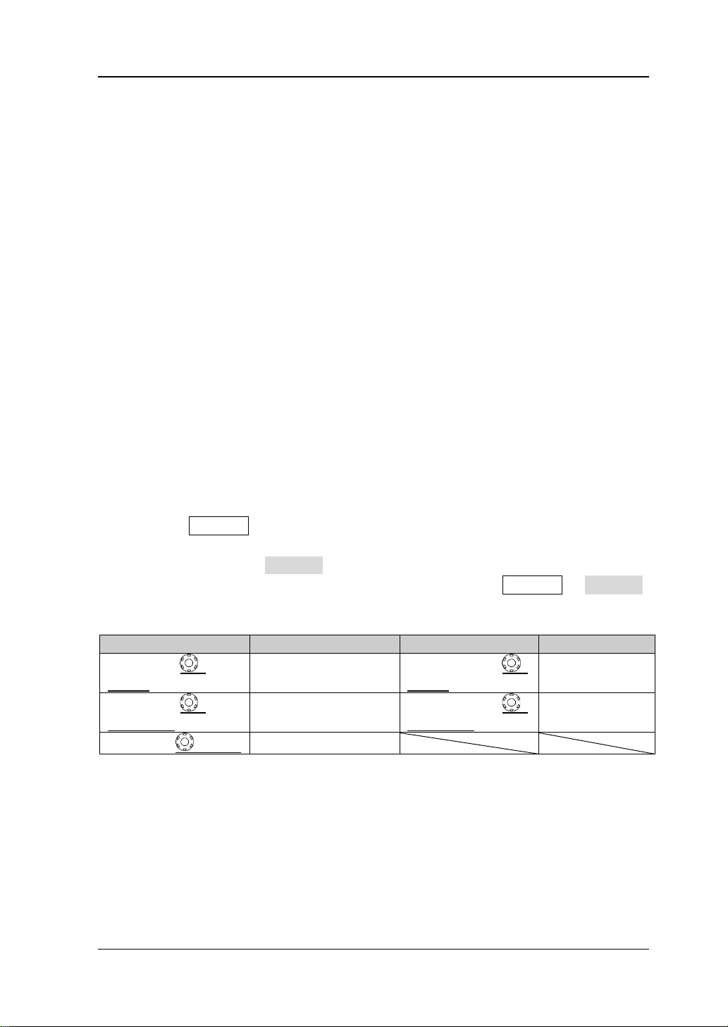
4. Knob: the expression method of each knob is as shown in the “Logo” column in
the table below.
VERTICAL
SCALE
VERTICAL
HORIZONTAL
SCALE
HORIZONTAL
Knob
DS1000Z User’s Guide
Scale Knob
Position Knob
Page 20
RIGOL
XVIII
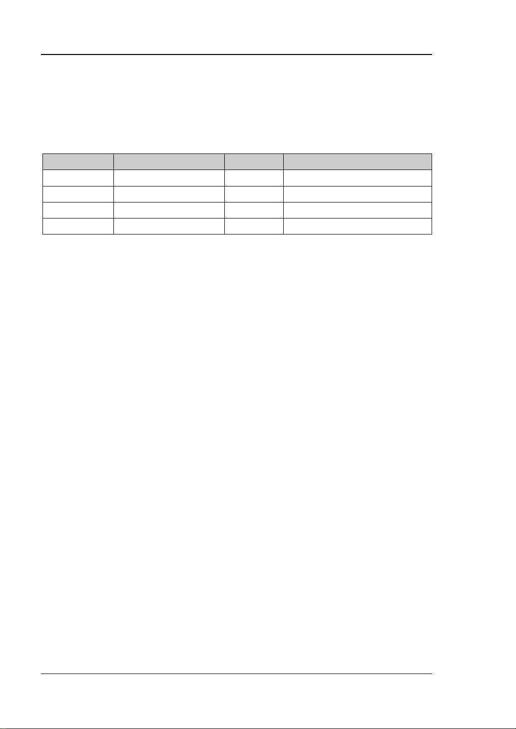
Content Conventions in this Manual:
DS1000Z series includes the following models. This manual takes DS1104Z-S for
example and the descriptions here have contained all the functions and
performances of other models.
Model Analog bandwidth Channels Cahnnels for signal source
DS1104Z 100 MHz 4 -DS1074Z 70 MHz 4 -DS1104Z-S 100 MHz 4 2
DS1074Z-S 70 MHz 4 2
DS1000Z User’s Guide
Page 21

Contents RIGOL
XIX
Contents
Guaranty and Declaration ......................................................................... I
Safety Requirement ................................................................................ II
General Safety Summary ........................................................................... II
Safety Terms and Symbols ....................................................................... IV
Allgemeine Sicherheits Informationen ......................................................... V
Sicherheits Begriffe und Symbole ............................................................. VII
Measurement Category .......................................................................... VIII
Ventilation Requirement ........................................................................... IX
Working Enviro nment ............................................................................... X
General Care and Cleaning ...................................................................... XII
Environmental Considerations ................................................................. XIII
DS1000Z Series Overview .................................................................... XIV
Document Overview ............................................................................. XVI
Chapter 1 Quick Start ......................................................................... 1-1
General Inspection ................................................................................ 1-2
Appearance and Dim e nsions ................................................................... 1-3
To Prepare the Oscilloscope for Use ......................................................... 1-4
To Adjust the Supporting Legs .......................................................... 1-4
To Connect to Power Suppl y............................................................. 1-5
Power-on Inspection ....................................................................... 1-6
To Connect the Probe ...................................................................... 1-7
Function Inspection ......................................................................... 1-8
Probe Compensation ...................................................................... 1-10
Front
Panel Overview ............................................................................ 1-11
Rear Panel Overview ............................................................................. 1-12
Front Panel Function Overview............................................................... 1-14
VERTICAL ..................................................................................... 1-14
Source .......................................................................................... 1-15
HORIZONTAL ................................................................................ 1-15
TRIGGER ...................................................................................... 1-16
CLEAR .......................................................................................... 1-16
AUTO............................................................................................ 1-16
DS1000Z User’s Guide
Page 22

RIGOL Contents
XX
RUN/STOP .................................................................................... 1-17
SINGLE ......................................................................................... 1-17
Knob ............................................................................................ 1-17
Function Menu .............................................................................. 1-18
Print ............................................................................................. 1-19
User Interface ...................................................................................... 1-20
Parameter Setting Methods ................................................................... 1-24
To Use the Security Lock ....................................................................... 1-25
To Use the Built-in Help System ............................................................. 1-26
Chapter 2 To Set the Vertical System ................................................. 2-1
To Enable the Channel ............................................................................ 2-2
Channel Coupling ................................................................................... 2-3
Bandwidth Limit ..................................................................................... 2-3
Probe Ratio ........................................................................................... 2-4
Waveform Invert .................................................................................... 2-5
Vertical Scale ......................................................................................... 2-5
Vertical Expansion .................................................................................. 2-6
Amplitude Unit ....................................................................................... 2-6
Channel Label ........................................................................................ 2-7
Delay Calibration .................................................................................... 2-8
Chapter 3 To Set the Horizontal System ............................................ 3-1
Delayed Sweep ...................................................................................... 3-2
Time Base Mode .................................................................................... 3-4
YT Mode ......................................................................................... 3-4
XY Mode ......................................................................................... 3-5
Roll Mode ....................................................................................... 3-8
Chapter 4 To Set the Sample System ................................................. 4-1
Acquisition Mode .................................................................................... 4-2
Normal ........................................................................................... 4-2
Average .......................................................................................... 4-2
Peak Detect .................................................................................... 4-3
High Resolution ............................................................................... 4-3
Sin(x)/x ................................................................................................. 4-4
Sample Rate .......................................................................................... 4-4
Memory Depth ....................................................................................... 4-6
Antialiasing ............................................................................................ 4-7
DS1000Z User’s Guide
Page 23

Contents RIGOL
XXI
Chapter 5 To Trigger the Oscilloscope ................................................ 5-1
Trigger Source ...................................................................................... 5-2
Trigger Mode ........................................................................................ 5-3
Trigger Coupling .................................................................................... 5-5
Trigger Holdoff ...................................................................................... 5-6
Noise Rejection ..................................................................................... 5-7
Trigger Type ......................................................................................... 5-8
Edge Trigger ................................................................................... 5-9
Pulse Trigger ................................................................................. 5-10
Slope Trigger ................................................................................. 5-12
Video Trigger ................................................................................. 5-16
Pattern Trigger .............................................................................. 5-18
Duration Trigger ............................................................................ 5-20
Setup/Hold Trigger (Option) ............................................................ 5-22
TimeOut Trigger (Option) ............................................................... 5-24
Runt Trigger (Option) ..................................................................... 5-26
Windows Trigger (Option) ............................................................... 5-29
Delay Trigger (Option) .................................................................... 5-31
Nth Edge Trigger (Option) ............................................................... 5-33
RS232 Trigger (Option) ................................................................... 5-35
I2C Trigger (Option) ....................................................................... 5-37
SPI Trigger (Option) ....................................................................... 5-40
Trigger Output Connector ...................................................................... 5-42
Chapter 6 To Make Measurements.................................................... 6-43
Math Operation .................................................................................... 6-44
Addition ........................................................................................ 6-44
Substraction .................................................................................. 6-45
Multiplication ................................................................................. 6-45
Division ......................................................................................... 6-46
FFT .............................................................................................. 6-47
“AND” Operation ............................................................................ 6-50
“OR” Operation .............................................................................. 6-52
“XOR” Operation ............................................................................ 6-53
“NOT” Operation ............................................................................ 6-54
Integrate ...................................................................................... 6-55
Differentiate .................................................................................. 6-55
Square Root .................................................................................. 6-56
DS1000Z User’s Guide
Page 24

RIGOL Contents
XXII
Base 10 Logarithm ......................................................................... 6-57
Natural Logarithm .......................................................................... 6-57
Exponential ................................................................................... 6-58
Absolute Value .............................................................................. 6-59
Auto Measurement ............................................................................... 6-60
Quick Measurement after AUTO ...................................................... 6-60
One-key Measurement of 32 Parameters .......................................... 6-61
Frequency Counter Measurement .................................................... 6-67
Measurement Setting ..................................................................... 6-68
To Clear the Measurement .............................................................. 6-69
All Measurement ............................................................................ 6-70
Statistic Function ........................................................................... 6-71
Cursor Measurement ............................................................................ 6-72
Manual Mode ................................................................................ 6-73
Track Mode ................................................................................... 6-76
Auto Mode .................................................................................... 6-78
XY Cursor Measurement ................................................................. 6-79
Chapter 7 Protocol Decoding ............................................................. 7-1
Parallel Decoding ................................................................................... 7-2
RS232 Decodi n g (Option) ....................................................................... 7-7
I2C Decoding (Option) .......................................................................... 7-13
SPI Decoding (Option) .......................................................................... 7-17
Chapter 8 Reference Waveform ......................................................... 8-1
To Enable REF Function .......................................................................... 8-2
To Select REF Source .............................................................................. 8-2
To Adjust REF Waveform Display ............................................................. 8-2
To Save to Internal Memory .................................................................... 8-3
To Set the Color ..................................................................................... 8-3
To reset the REF waveform ..................................................................... 8-3
To Export to Internal or External Memory ................................................. 8-3
To Import from Internal or External Memor y ............................................. 8-4
Chapter 9 Pass/ Fail Test .................................................................... 9-1
To Enable Pass/Fail Test .......................................................................... 9-2
To Select Source .................................................................................... 9-2
Mask Range ........................................................................................... 9-2
Test and Ouput ...................................................................................... 9-3
DS1000Z User’s Guide
Page 25

Contents RIGOL
XXIII
To Save the Test Mask ........................................................................... 9-4
To Load the Test Mask ........................................................................... 9-4
Chapter 10 Waveform Record ...................................................... 10-1
Playback Setting ................................................................................... 10-2
Record Setting ..................................................................................... 10-3
Chapter 11 Display Control .......................................................... 11-1
To Select the Display Type ..................................................................... 11-2
To Set the Persistence Time .................................................................. 11-3
To Set the Waveform Intensity ............................................................... 11-5
To Set the Screen Grid .......................................................................... 11-5
To Set the Grid Brightness ..................................................................... 11-5
Chapter 12 Signal Source ............................................................. 12-1
To Output Basic Waveform .................................................................... 12-2
To Output Sine Waveform ............................................................... 12-2
To Output Square Waveform ........................................................... 12-4
To Output Ramp Waveform ............................................................. 12-4
To Output Pulse Waveform .............................................................. 12-5
To Output DC Waveform ................................................................. 12-5
To Output Noise Waveform ............................................................. 12-6
To Output Built-In Waveform ................................................................. 12-7
To Output Arbitrary Waveform ............................................................. 12-12
To Select Waveform ..................................................................... 12-14
To Create Waveform ..................................................................... 12-14
To Edit Waveform ........................................................................ 12-16
Modulation ........................................................................................ 12-18
AM ............................................................................................. 12-18
FM ............................................................................................. 12-20
Chapter 1 3 St ore and Recall ......................................................... 13-1
Storage System .................................................................................... 13-2
Storage Type ....................................................................................... 13-3
Internal Storage and Recall ................................................................... 13-5
External Storage and Recall ................................................................... 13-6
Disk Management ................................................................................. 13-7
To Select File Type ......................................................................... 13-8
To Create a New File or Folder ........................................................ 13-9
DS1000Z User’s Guide
Page 26

RIGOL Contents
XXIV
To Delete a File or Folder .............................................................. 13-12
To Rename a File or Folder ........................................................... 13-13
To Clear the Local Memory ........................................................... 13-13
Factory.............................................................................................. 13-14
Chapter 14 System Func tion Settin g............................................ 14-1
Remote Int e rface Configuration ............................................................. 14-2
LAN Setting ................................................................................... 14-2
To Select USB Device ..................................................................... 14-6
To Set the GPIB Address ................................................................ 14-6
System-related .................................................................................... 14-7
Sound .......................................................................................... 14-7
Language ..................................................................................... 14-7
System Informat i on ....................................................................... 14-8
Power-on Recall ............................................................................. 14-8
Self-calibration .............................................................................. 14-9
Option Management .................................................................... 14-10
Auto Options ............................................................................... 14-11
Key Lock ..................................................................................... 14-12
Chapter 15 Remote Control ......................................................... 15-1
Remote Control via USB ........................................................................ 15-2
Remote Control via LAN ........................................................................ 15-6
Remote Control via GPIB ....................................................................... 15-9
Chapter 16 Troubleshooting ........................................................ 16-1
Chapter 17 Specifications ............................................................ 17-1
Chapter 18 Appendix ................................................................... 18-1
Appendix A: Accessories and Options ..................................................... 18-1
Appendix B: Warranty ........................................................................... 18-2
Index ........................................................................................................ 1
DS1000Z User’s Guide
Page 27

Chapter 1 Quick Start RIGOL
1-1
Chapter 1 Quick Start
This chapter introduces the preparations when using the oscilloscope for the first
time, the front panel, rear panel and user interface of the oscilloscope as well as t he
using method of the built-in help system.
The contents of this chapter:
General Inspection
Appearance and Dimensions
To Prepare the Oscilloscope for Use
Front
Rear Panel Overview
Front Panel Function Overview
User Interface
Parameter Setting Methods
To Use the Security Lock
To Use the Built-in Help System
Panel Overview
DS1000Z User’s Guide
Page 28

RIGOL Chapter 1 Quick Start
1-2
General Inspection
1. Inspect the shipping container for damage.
Keep the damaged shipping container or cushioning material until the contents
of the shipment have been checked for completeness and the instrument has
passed both ele ctrica l a nd mechanical tests.
The consigner or carrier shall be liable for the damage to instrument resulting
from shipment. RIGOL woul d n ot be responsible f or free maintenance/rework
or replacement of the unit.
2. Inspect the instrument.
In case of any damage, or defect, or failure, notify your RIGOL sales
representative.
3. Check the Accessories
Please check the accessories according to the packing l is t s. If t he accessories
are incomplete or damaged, pleas e contact your RIGOL sales representative.
DS1000Z User’s Guide
Page 29
Chapter 1 Quick Start RIGOL
1-3
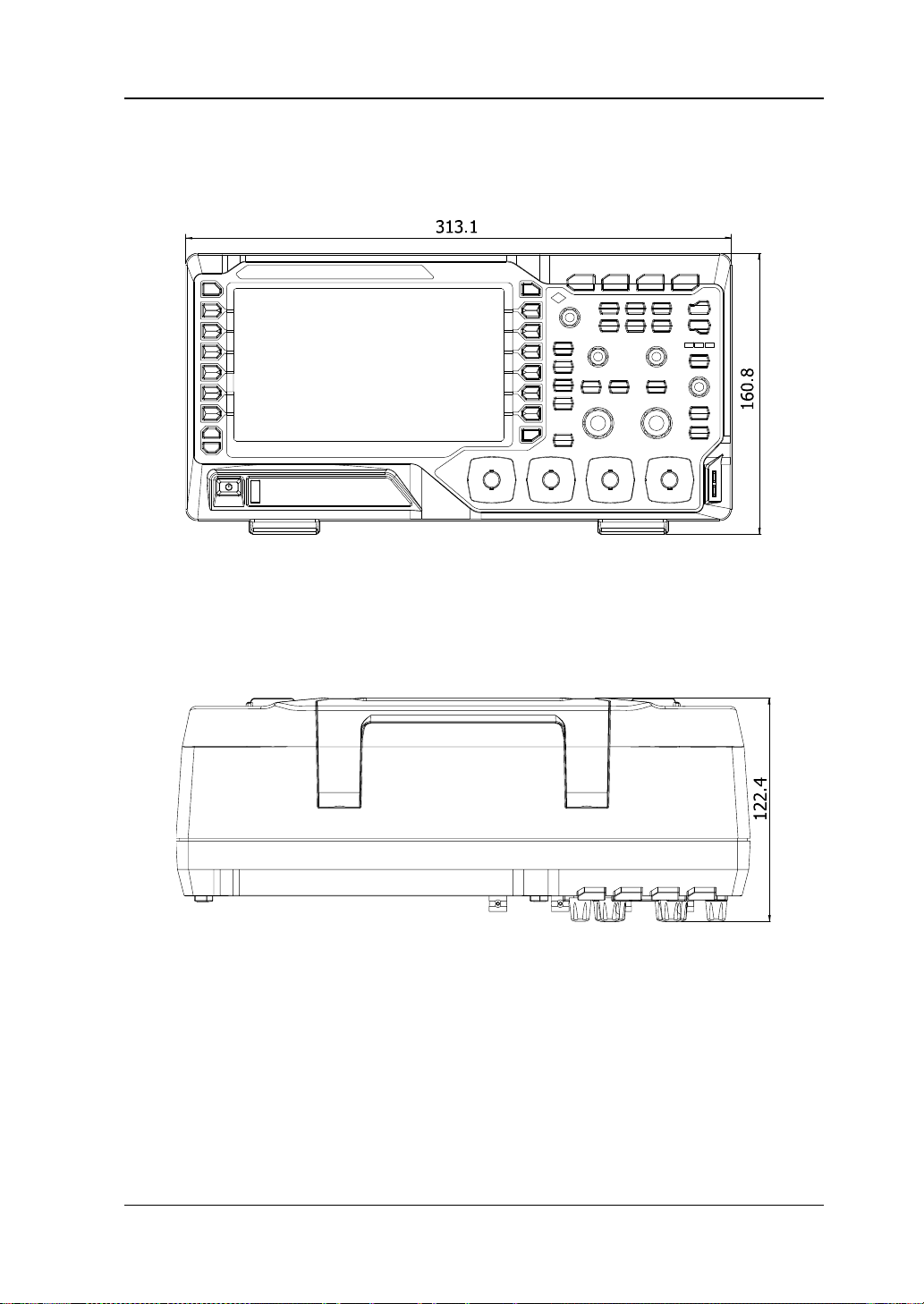
Appearance and Dimensions
Figure 1-1 Front View Unit: mm
Figure 1-2 Top View Unit: mm
DS1000Z User’s Guide
Page 30
RIGOL Chapter 1 Quick Start
1-4
To Prepare the Oscilloscope for Use
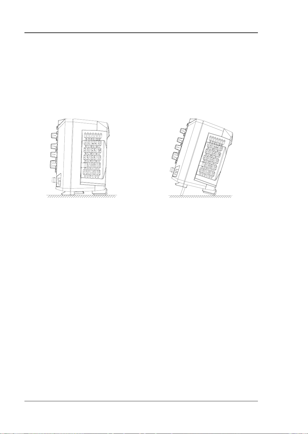
To Adjust the Supporting Legs
Adjust the supporting legs properly to use them as stands to tilt the oscilloscope
upwards for stable placement of the oscilloscope as well as better operation and
observation.
Figure 1-3 To Adjust the Supporting Legs
DS1000Z User’s Guide
Page 31
Chapter 1 Quick Start RIGOL
1-5
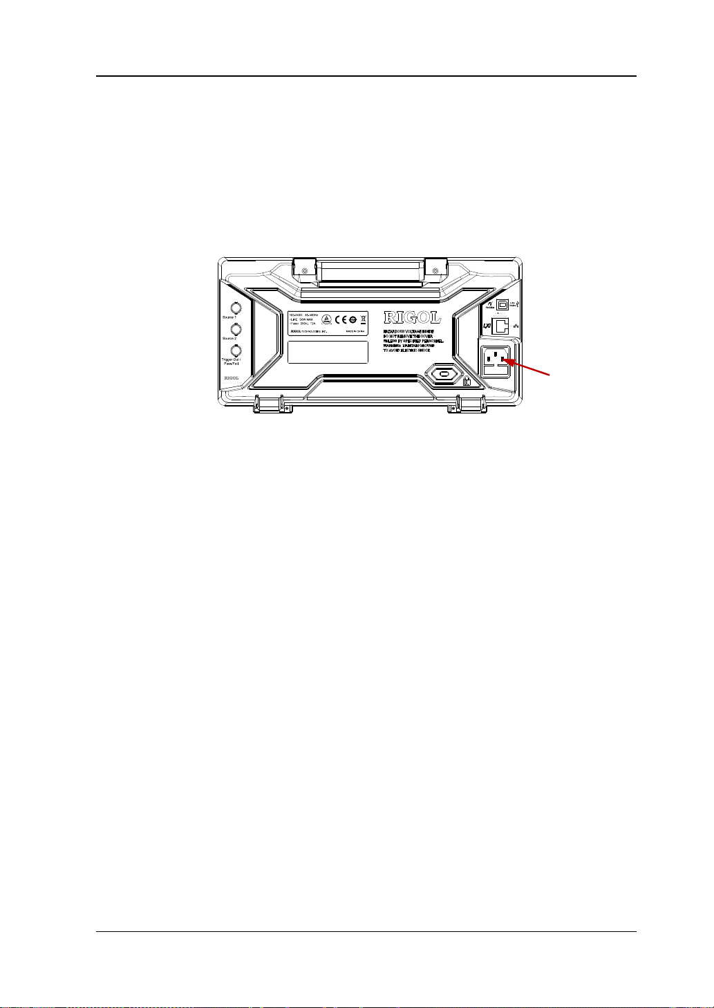
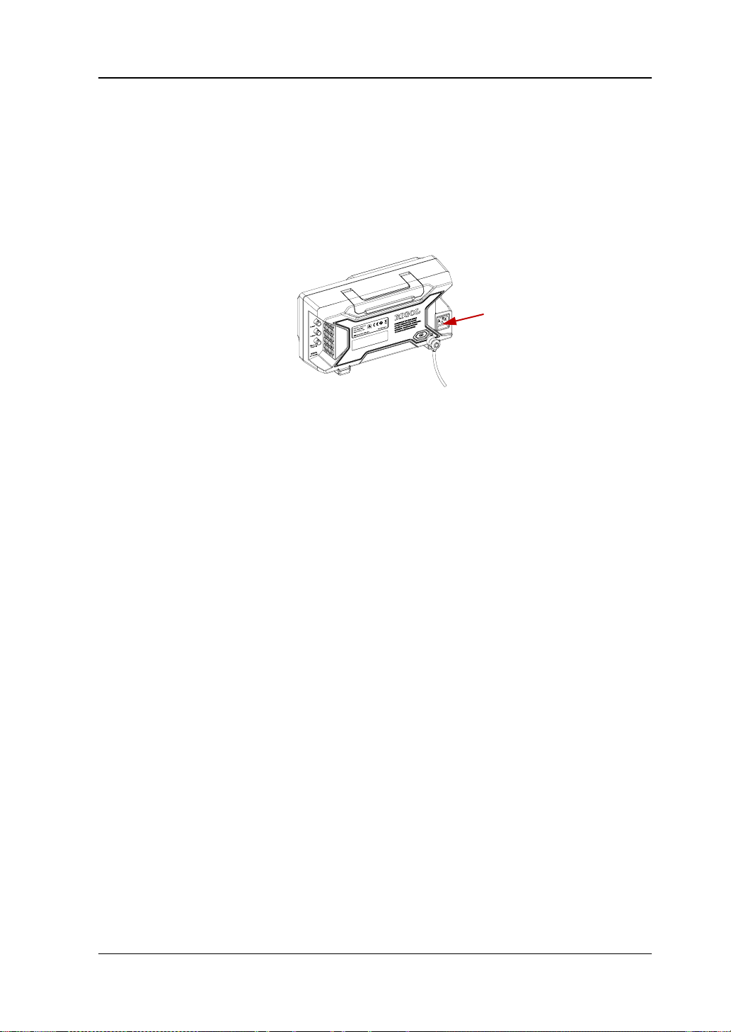
To Connect to Power Supply
The power requirements of DS1000Z are 100-240 V, 45-440 Hz. Please use the
power cord supplied with the accessories to connect the os cilloscope to the AC power
source.
Power Socket
Figure 1-4 To Connect to Power Source
DS1000Z User’s Guide
Page 32

RIGOL Chapter 1 Quick Start
1-6
Power-on Inspection
When the oscilloscope is energized, press the power key
of the front panel to start the oscilloscope. During the start-up process, the
oscilloscope performs a series of self-tests and after the self-test is finished, the
welcome screen is displayed and you can view the Option name, Option Edition and
Left time of the option currently installed in the “Installed Options” p op-up dialog box
on the screen. When the instrument is shipped, a trial version of the option is
provided and the left time is about 2000 minutes.
at the lower-left corner
Figure 1-5 Installed Options
DS1000Z User’s Guide
Page 33

Chapter 1 Quick Start RIGOL
1-7
To Connect the Probe
RIGOL provides passive probe for the DS1000Z series oscilloscopes, as shown in the
table below. For detailed technical information of the probe, please refer to the
corresponding Probe User’s Guide.
Model Description
RP2200 150 MHz, passive probe, standard
Connect the Probe:
1. Connect the BNC terminal of the probe to a channel BNC connector of the
oscilloscope at the front panel.
2. First connect the ground alligator clip of t he probe t o the cir cuit ground terminal
and then connect the probe tip to the circuit point to be tested.
Figure 1-6 To Connect the Probe
DS1000Z User’s Guide
Page 34

RIGOL Chapter 1 Quick Start
1-8
o avoid electric shock during the use of probe, please make sure that
Function Inspection
1. Press Storage Default to restore the instrument to its default configuration.
2. Connect the ground alligator clip of the probe to the “Ground Terminal” under
the probe compensation signal output terminal.
3. Use the probe to connect the input terminal of CH1 of the oscilloscope and the
“Compensation Signal Output Terminal” of the probe.
Compensation Signal Output Terminal
Ground Terminal
Figure 1-7 To Use the Compensation Signa l
4. Press AUTO.
5. Observe the wa veform on the display. In normal condition, the display should be
a square waveform as shown in the figure below:
Figure 1-8 Square Waveform
6. Use the same method to test the other channels. If the square waveforms
actually shown do not match that in the figure above, please perform “Probe
Compensation” in the next section.
WARNING
T
the insulated wire of the probe is in good condition and do not touch
the metallic part of the probe when the probe is connected to high
voltage source.
DS1000Z User’s Guide
Page 35

Chapter 1 Quick Start RIGOL
1-9
Tip
probe compensation adjustment and can not be used for calibration.
The signal output from the probe compensation connector can only be used for
DS1000Z User’s Guide
Page 36

RIGOL Chapter 1 Quick Start
1-10
Probe Compensation
When the probes are used for the first time, you should compensate the probes to
match the input channels of the oscilloscope. Non-com pe n s a t e d or poorly
compensate d probes may cause measurement inaccuracy or error. The probe
compensation procedures are as follows.
1. Perform steps 1, 2, 3 and 4 of “Function Inspection” in the previous section.
2. Check the waveforms displayed and compare them with the following.
3. Use a nonmetallic driver to adjust the low-frequency compensation adjustment
Over compensated Perfectly compensated Under c o m pen sated
Figure 1-9 Probe Compensation
hole on the probe until the waveform displayed is as the “Perfectly
compensated” in the figure above.
DS1000Z User’s Guide
Page 37

Chapter 1 Quick Start RIGOL
1-11
[1]
Front Panel Overview
1 2
3 4 5 6 7 8 9
10 11 12 13 14 15 16 17 18
Figure 1-10 Front Panel Overview
Table 1-1 Front Panel Description
No. Description No. Description
1 Measurement Menu
Softkeys
10
Power Key
2 LCD 11 USB HOST
3 Multi-function K no b 12 Function Menu Softkeys
4 Function Menu Keys 13 Analog Channel Input Area
5 CLEAR 14 Source
6 AUTO 15 VERTICAL
7 RUN/STOP 16 HORIZONTAL
8 SINGLE 17 TRIGGER
9 Help&Print 18 Probe Compensation Signal Output
Terminal/Ground Terminal
[1]
Note
: Only applicable to DS1104Z-S and DS1074Z -S.
DS1000Z User’s Guide
Page 38
RIGOL Chapter 1 Quick Start
1-12
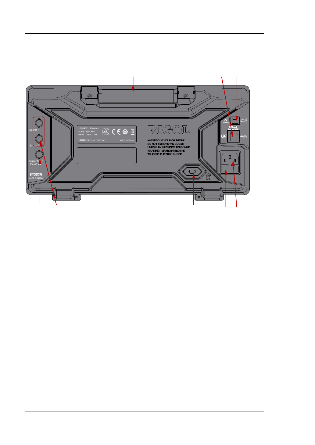
Rear Panel Overview
4 5 6 7 8
1 2 3
Figure 1-11 Rear Panel Overview
1. Handle
Pull up the handle vertically for easy carrying of the instrument. When you do
not need the handle, press it down.
2. LAN
Connect the instrument to the network via this interface fo r remote cont rol. This
oscilloscope conforms to the LXI Core Device 2011 class instrument standards
and can quickly build test system with other instruments.
3. USB DEVICE
PictBridge printer or PC can be connected via this interface to print waveform
displayed on the screen or control the instrument using PC s oftware by sending
SCPI commands or user-defined programming.
DS1000Z User’s Guide
Page 39

Chapter 1 Quick Start RIGOL
1-13
4. Trigger Out/Pass/Fail
Trigger Out
The oscilloscope outputs a signal that can reflect the current capture rate of
the oscilloscope at each trigger via this connector. You can connect the
signal to a waveform display instrument to measure the frequency of the
signal. The measurement result is equal to the current capture rate.
Pass/Fail
In the pass/fail test, this connector outputs a high level when failed
waveforms are detected by the oscilloscope and outputs low level when
passed waveforms are detected by the oscilloscope.
5. Source Output
The oscilloscope provides two built-in source channel output terminals. When
the output of Source1 or Source2 is enabled, the [Source1] or [Source2]
connectors at the rear panel outputs the current signal.
6. Lock Hole
You can lock the instrument to a fixed location using the security lock (please
buy it yourself) via the lock hole.
7. Fuse
If a new fuse is required, please use the specified fuse (250V, T2A) and follow
the steps below.
a) Turn off the instrument and remove the power cord.
b) Insert a straight screwdriver into the slot at t he power socket and prize out
the fuse seat gently.
c) Take out the fuse and replace it with s pecified fuse, and then install the fuse
seat to the original position.
8. AC Power Socket
AC power input terminal. The power requirements of this oscilloscope are
100-240 V, 45-440 Hz. Use the power cord provided with the accessories to
connect the instrument to AC power. Then, you can press the power key at the
front panel to start the instrument.
DS1000Z User’s Guide
Page 40

RIGOL Chapter 1 Quick Start
1-14
Front Panel Function Overview
VERTICAL
CH1, CH2, CH3, CH4: analog input channels. The 4
channels are marked b y different colors which are als o
used to mark both the corresponding waveforms on
the screen and the channel input connectors. Press
any key to open t he corre sponding channel menu a nd
press again to turn off the channel.
MATH: press this key to open the math operation
menu under which add, subtract, multiply , divide , FFT,
A&&B, A||B, A^B, !A, Intg, Diff, Sqrt, Lg, Ln, Exp and
Abs are provided.
REF: press this key to enable the reference waveform function to compare the
waveform actually tested with the reference waveform.
Vertical
waveform. Turn clockwise to increase the position and turn counterclockwise to
decrease. During the modific ation, the waveform would move up and down and the
position message (e.g.
change accordingly. Press down this knob to quickly reset the vertical position to
zero.
POSITION: modify the vertical position of the current channel
) at the lower-left corner of the screen would
VERTICAL
clockwis e to decrease the scale and turn counterclockwise to increase. During the
modification, the amplitude of the waveform would enlarge or reduce and the scale
information (e.g.
accordingly. Press down this knob to quickly switch the vertical scale adjustment
modes between “Coarse” and “Fine”.
SCALE: modify the vertical scale of the current channel. Turn
) at the lower side of the screen would change
DS1000Z User’s Guide
Page 41

Chapter 1 Quick Start RIGOL
1-15
Press this key to enter the sou rce set ting inter face . You can set
the horizontal control menu under whi ch to turn o n
Tip
How to set the vertical scale and vertical position of each channel?
The four channels of the DS1000Z series digital oscilloscope use the same set of
VERTICAL
scale and vertical position of a channel, press CH1, CH2, CH3 or CH4 to select
the desired channel and then rotate the VERTICAL POSITION and
VERTICAL
POSITION and VERTICAL SCALE knobs. To set the vertical
SCALE knobs.
Source
the waveform of the output signal of the source and the
waveform parameters, turn on or off the outputs of the
[Source1] and [Source2] connectors at the rear panel, view
the signal states (such as the frequency, amplitude, offset and
phase).
HORIZONTAL
HORIZONTAL POSITION: modify the horizontal position.
The trigger point would move left or right relative to the center of
the screen when you turn the knob. During the modification,
waveforms of all the channels would move left or right and the
horizontal position message (e.g.
upper-right corner of the screen would change accordingly. Press
down this knob to quickly reset the horizontal position (or the
delayed sweep position).
MENU: press this key to open
or off the delayed sweep function, switch between different time base modes.
HORIZONTAL SCALE: modify the horizontal time base. Turn clockwise to
reduce the time base and turn counte r clo ckwise to increase the time base. During
the modif ication, waveforms of all the channels will be displayed in expanded or
) at the
DS1000Z User’s Guide
Page 42
RIGOL Chapter 1 Quick Start
1-16
compressed mode and the time base message (e.g. ) at the upper side of
the screen would change accordingly. Press down this knob to quickly switch to
delayed sweep state.
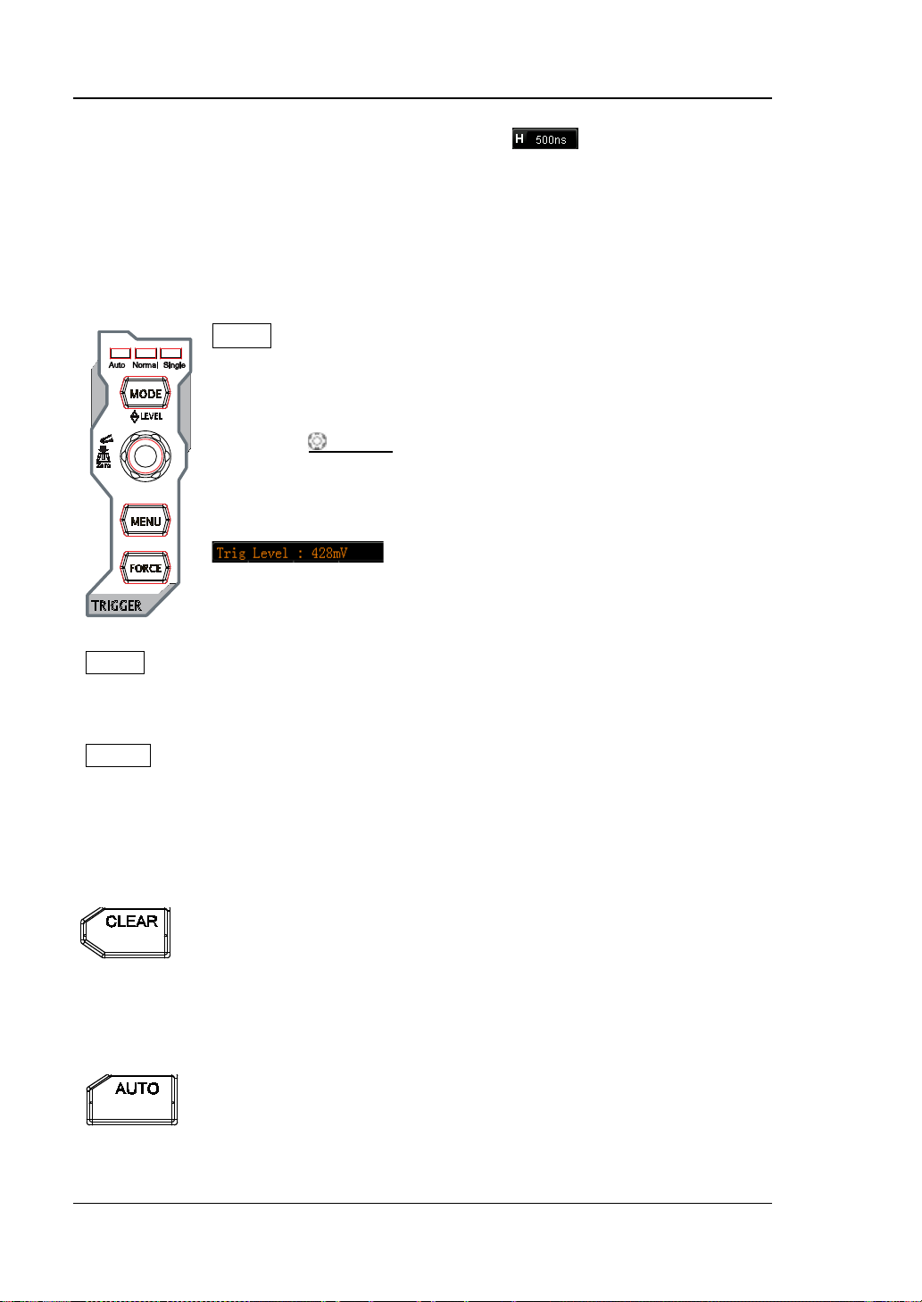
TRIGGER
MODE: press this key to switch the trigger mode to Auto, Normal
or Single and th e corresponding state backlight of the current
trigger mode would be illuminated.
TRIGGER
increase the level and turn counterclockwise to reduce the level.
During the modification, the trigger level line would move up and
down and the value in the trigger level message box (e.g.
change accordingly. Press down the knob to quickly reset the
trigger level to zero point.
LEVEL: modify the trigger level. Turn clockwise to
) at the lower-left corner of the screen would
MENU: press this key to open the trigger operation menu. This oscilloscope
provides various trigger types (for details, refer t o the int roductions in “To Trigger
the Oscilloscope
FORCE: press this key to generate a trigger signal forcefully.
”).
CLEAR
Press this key to clear all the waveforms on the screen. If the
oscilloscope is in “RUN” state, new w avefor ms will still be display ed.
AUTO
Press this key to enable the waveform auto setting function. The
oscilloscope will automatically adjust the vertical scale, horizontal
time base and trigger mode ac cor ding to the input signal to realize
DS1000Z User’s Guide
Page 43

Chapter 1 Quick Start RIGOL
1-17
optimum waveform display. Note that auto setting requires that the
frequency of the signal under test should be no lower than 41Hz,
the duty cycle be greater than 1% and the amplitude be at least
20mVpp. Otherwise, “Auto detected none!” would be displayed
after pressing this key and the quick paramet er me a sure ment
menu might not be displayed.
RUN/STOP
Press this key to set the state of the oscilloscope to “RUN” or
“STOP”. In “RUN” state, the key is illuminated in yellow. In “STOP”
state, the key is illuminated in red.
SINGLE
Press this key to set the trigger mode to “Single”. In single trigger
mode, press FORCE to generate a trigger signal immediately.
Knob
Adjust waveform brightness:
In non-menu-operation mode, turn this knob to adjust
the brightness of wa vefo rm dis play. The adjustable range
is from 0% to 100 %. Turn clockwise to increase the
brightness and counterclockwise to reduce. Press down
Multifunction Knob (the backlight goes on during operation):
In menu operation, press any menu softkey and turn the knob to switch the desired
submenu under this menu and then press down the knob to select the current
submenu. It can also be used to modify para mete rs and input filename. In addition,
DS1000Z User’s Guide
this knob to reset the brightness to 50%.
You can also press Display Intensity and use the
knob to adjust the waveform brightness.
Page 44

RIGOL Chapter 1 Quick Start
1-18
for DS1000Z-S models oscilloscope, in the source interface, press the corresponding
menu softkey and then press the knob; the numeric keyboard will pop-up on the
screen and you can input the desired parameter value and unit directly using this
knob.
Function Menu
Measure: press this key to open the measurement setting menu. You can set the
measurement source as well as turn on or off the frequency counter, all measure and
statistic function etc. Press MENU at the left of the screen to switch the
measurement menus of 32 waveform parameters. Then, press down the
corresponding menu softkey to quickly realize one-key measurement and the
measurement result will be displayed at the bottom of the screen.
Acquire: press this key to enter the sample setting menu to set the acquisition
mode a nd memory depth of the oscilloscope.
Storage: press this key to enter file store and recall interface. The storable file
types include picture, traces, waveforms, setups, CSV and parameter. Internal and
external storage as well as disk management are also supported.
Cursor: press this key to enter cursor measurement menu. The oscilloscope
provides manual, track, auto and XY cursor modes. Wherein, the XY mode is only
valid when the time base mode is “XY”.
Display: press this key to enter display setting menu to set the display type,
persistence time, wave intensity, grid type and grid bri gh t n e s s o f the waveform.
Utility: press this key to enter the system function setting menu to set the
system-related functions or parameters, such as I/O setting, sound and language.
Besides, some a dv a n ce d f u ncti ons (s u ch as pa ss/f a il t est , w a v ef or m rec o rd) a re also
supported.
DS1000Z User’s Guide
Page 45

Chapter 1 Quick Start RIGOL
1-19
pressing this key will save the screen to the USB storage device in
“.png” format. If the current storage type is picture, the screen will be
saved in the U SB storage dev ice in picture format (BMP8, BMP24, PNG
and TIFF).
DS1000Z User’s Guide
Page 46
RIGOL Chapter 1 Quick Start
1-20
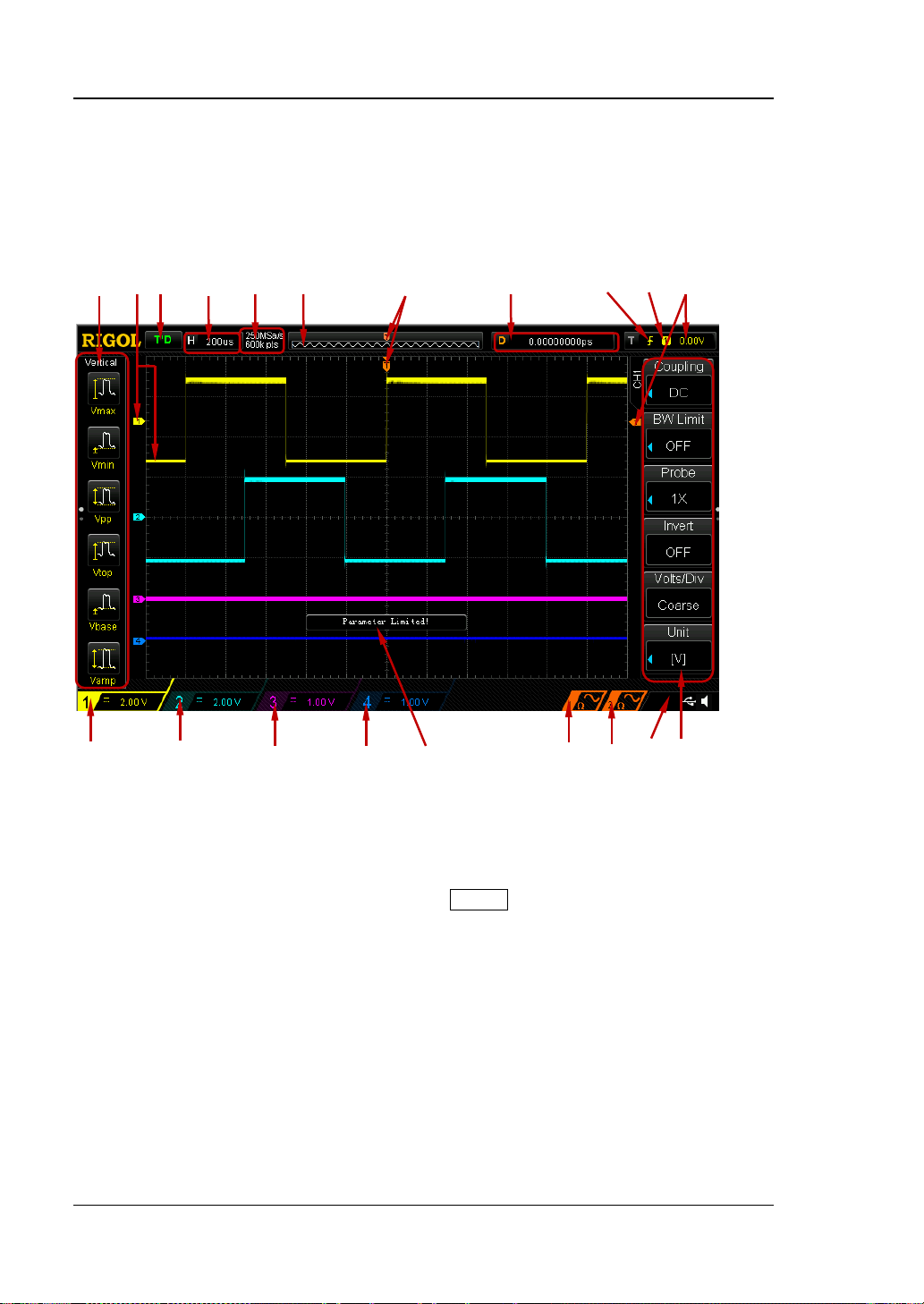
User Interface
DS1000Z provides 7.0 inches, WVGA (800*480) 160,000 color TFT LCD.
1 2 3 4 5 6 7 8 9 10 11
12 13 14 15 16 17 18 19 20
Figure 1-12 User Interface
1. Auto Measurement Items
Provide 16 horizontal (HORIZONTAL) and 16 vertical (VERT I CAL) me asuremen t
parameters. Press the softkey at the left of the screen to activate the
corresponding measurement item. Press MENU continuously t o switch between
the horizontal and vertical parameters.
2. Channel Label/Waveform
Different channels are mar ked b y dif fere nt col ors an d the color of the w av efo rm
complies with the color of the channel.
3. Status
Available states include RUN, STOP, T’D (triggere d), WAIT and AUTO.
4. Horizontal Time Base
Represen t the tim e per grid on the horizontal axis on the screen.
DS1000Z User’s Guide
Page 47
Chapter 1 Quick Start RIGOL
1-21
Use HORIZONTAL SCALE to modify this parameter. The range
available is from 5 ns to 50 s.
5. Sample Rate/Memor y De p th
Display the current sample rate and memory depth of the oscilloscope.
Use HORIZONTAL
SCALE to modify this parameter.
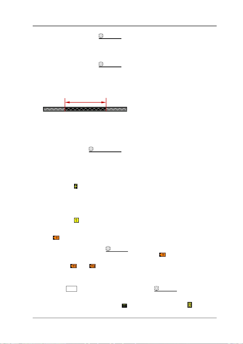
6. Waveform Memory
Provide t he schematic diagram of the memory position of the waveform
currently on the screen.
waveform on the
screen
7. Trigger Position
Display the trigger position of th e wav eform in the waveform memory and on
the screen.
8. Horizontal Position
Use HORIZONTAL
POSITION to modify this parameter. Press down the
knob to automatically set the parameter to zero.
9. Trigger Type
Display the currently selected trigger type and trigger condition setting.
Different labels are displayed when different trigger types are selected.
For example:
represents triggering on the rising edge in “Edge” trigger.
10. Trigger Source
Display the trigger source currently selected (CH1-CH4 or AC Line). Different
labels are displayed when different trigger sources are selected and t he color of
the trigger parameter area will change accordingly.
For example:
de notes that CH1 is sel ected as th e trigger source.
11. Trigger Level
at the right of the screen is the trigger level label and the trigger level
value is displayed at the upper-right corner of the screen.
When using TRIGGER
level value will change with the up and down of
LEVEL to modify the trigger level, the trigger
.
Note: In slope trigger, runt trigger and windows trigger, there are two trigger
level labels (
and ).
12. CH1 Vertical Scale
Display the voltage value per grid of CH1 waveform vertically.
Press CH1 to select CH1 and use VIRTICAL
SCALE to modify this
parameter.
The following labels will be displayed according to the current channel
setting: channel coupling (e.g.
) and bandwidth limit (e.g. ).
DS1000Z User’s Guide
Page 48

RIGOL Chapter 1 Quick Start
1-22
13. CH2 Vertical Scale
Display the voltage value per grid of CH2 waveform vertically.
Press CH2 to select CH2 and use VIRTICAL
SCALE to modify this
parameter.
The following labels will be displayed according to the current channel
setting: channel coupling (e.g.
) and bandwidth limit (e.g. ).
14. CH3 Vertical Scale
Display the voltage value per grid of CH3 waveform vertically.
Press CH3 to select CH3 and use VIRTICAL
SCALE to modify this
parameter.
The following labels will be displayed according to the current channel
setting: channel coupling (e.g.
) and bandwidt h limit (e.g. ).
15. CH4 Vertical Scale
Display the voltage value per grid of CH4 waveform vertically.
Press CH4 to select CH4 and use VIRTICAL
SCALE to modify this
parameter.
The following labels will be displayed according to the current channel
setting: channel coupling (e.g.
) and bandwidth limit (e.g. ).
16. Messa ge Box
Display pro mpt messages.
17. Source1 Waveform
Display the type of waveform currently set for Source1.
When the modulation of Source1 is enabled,
will be displayed at the
bottom of the Source1 waveform.
When the impedance of Source1 is set to 5 0 Ω,
will be displayed at the
bottom of the Source1 waveform.
Only available to DS1104Z-S and DS1074Z-S.
18. Source2 Waveform
Display the type of waveform currently set for Source1.
When the modulation of Source2 is enabled,
will be displayed at the
bottom of the Source2 waveform.
When the impedance of Source2 is set to 5 0 Ω,
will be displayed at the
bottom of the Source2 waveform.
Only available to DS1104Z-S and DS1074Z-S.
19. Notification Area
Display system time, sound icon and USB disk icon.
Sound Icon: when sound is enabled,
will be displayed. Press Utility
Sound to enable or disable the sound.
USB Disk Icon: when a USB disk is detected, will be displa yed.
20. Operation MEN U
Press any softkey to activate the corresponding menu.
DS1000Z User’s Guide
Page 49

Chapter 1 Quick Start RIGOL
1-23
The number of the dots denotes that the number of the pages the
current menu has.
The following symbols might be displayed in the menu:
Denote that the multifunction knob
to select parameter items. The backlight of the multifunction knob
at the front panel can be used
turns on when parameter selection is valid.
Denote that you can use the multifunction knob
parameter and then press down the multifunction k nob
the parameter. In this state, the backlight of the multif unction knob
to adj u st the
to select
is constant on.
Denote that press
the pop-up numeric ke yboard. The backlight of
to input desired paramrter values directly using
turns on when
parameter input is valid.
Denote that the current menu has several options.
Denote that the current menu has a lower level menu.
Press this key to return to the previous menu.
DS1000Z User’s Guide
Page 50

RIGOL Chapter 1 Quick Start
1-24
Parameter Setting Methods
DS1000Z supports the following two parameter setting methods.
Method 1:
For parameters displayed with
directly to set the desired value.
Method 2:
For parameters displayed with
and the numeric keyboard as shwon in the ficure below is displayed. Rotate the knob
to seelct the desired number and press the knob to input the num ber. After inputting
all the numbers, rotate the knob to select the desired unit and press the knob to
finish the parameter setting.
in the menu, rotate the multifunction knob
in the menu, press the multifunction knob
Figure 1-13 Numeric Ke yboard
Note: When using the numeric keyboard to input a parameter value, the length of
the value cannot exceed 10 digits. Otherwise, “DEL” will be selected automatically
and the input value will be deleted when you press knob again.
DS1000Z User’s Guide
Page 51
Chapter 1 Quick Start RIGOL
1-25
To Use the Security Lock
If needed, you can use the security lock (please buy it yourself) to lock t he
oscilloscope to a fixed location. The method is as f ollows, align the lock wi th the lo ck
hole and plug it into the lock hole vertically, turn the key clockwise to lock the
oscilloscope and then pull the key out.
Security Lock Hole
Figure 1-14 To Use the Security Lock
Note: Please do not insert other articles into the securi ty lock hole to avoid
damaging the instrument.
DS1000Z User’s Guide
Page 52

RIGOL Chapter 1 Quick Start
1-26
To Use the Built-in Help System
The help system of this oscilloscope provides instructions for all the function keys
(including menu keys) at t he front panel. Press Help to open the help interface and
press again to close the interface. The help interface mainly consists of two pa rt s .
The left is “Help Options” and you can use “Button” or “Index” mode to select. The
right is “Help Display Area”.
Help Options Help Display Area
Figure 1-15 Help Information
Button:
Default mode. In this mode, you can press the button (except the p ower key
various kinds of knobs
and the menu page up/down key / at the right of
, the
the screen) at the front panel directly to get the corresponding help information in
the “Help Display Area”. Use
to sel ect “To Index” and then press the knob to
switch to Index mode.
Index:
In this mode, use
to sel ect th e item tha t need s to get help (for example,
“Measure”). Press the knob to get the corresponding help information in the “Help
Display Area”. Use
to selec t “To Button” and then press the knob to switch to
Button mode.
DS1000Z User’s Guide
Page 53

Chapter 2 To Set the Vertical System RIGOL
2-1
Chapter 2 To Set the Vertical System
The contents of this chapter:
To Enable the Channel
Channel Coupling
Bandwidth Limit
Probe Ratio
Waveform Invert
Vertical Scale
Vertical Expansion
Amplitude Unit
Channel Label
Delay Calibration
DS1000Z User’s Guide
Page 54
RIGOL Chapter 2 To Set the Vertical System
2-2
To Enable the Channel
DS1000Z provides 4 analog input channels (CH1-CH4) and each channel can be
controlled independently. As the vertical syste m setting method s of the 4 channels
are completely the same, this chapter takes CH1 as an example to introduce the
setting method of the vertical system.
Connect a signal to the channel connect or of CH 1 and the n p ress CH1 in the v ertical
control area (VERTICAL) at the front panel to enable CH1. At this point, the channe l
setting menu is displa yed at the right side of the screen an d the channel label at t he
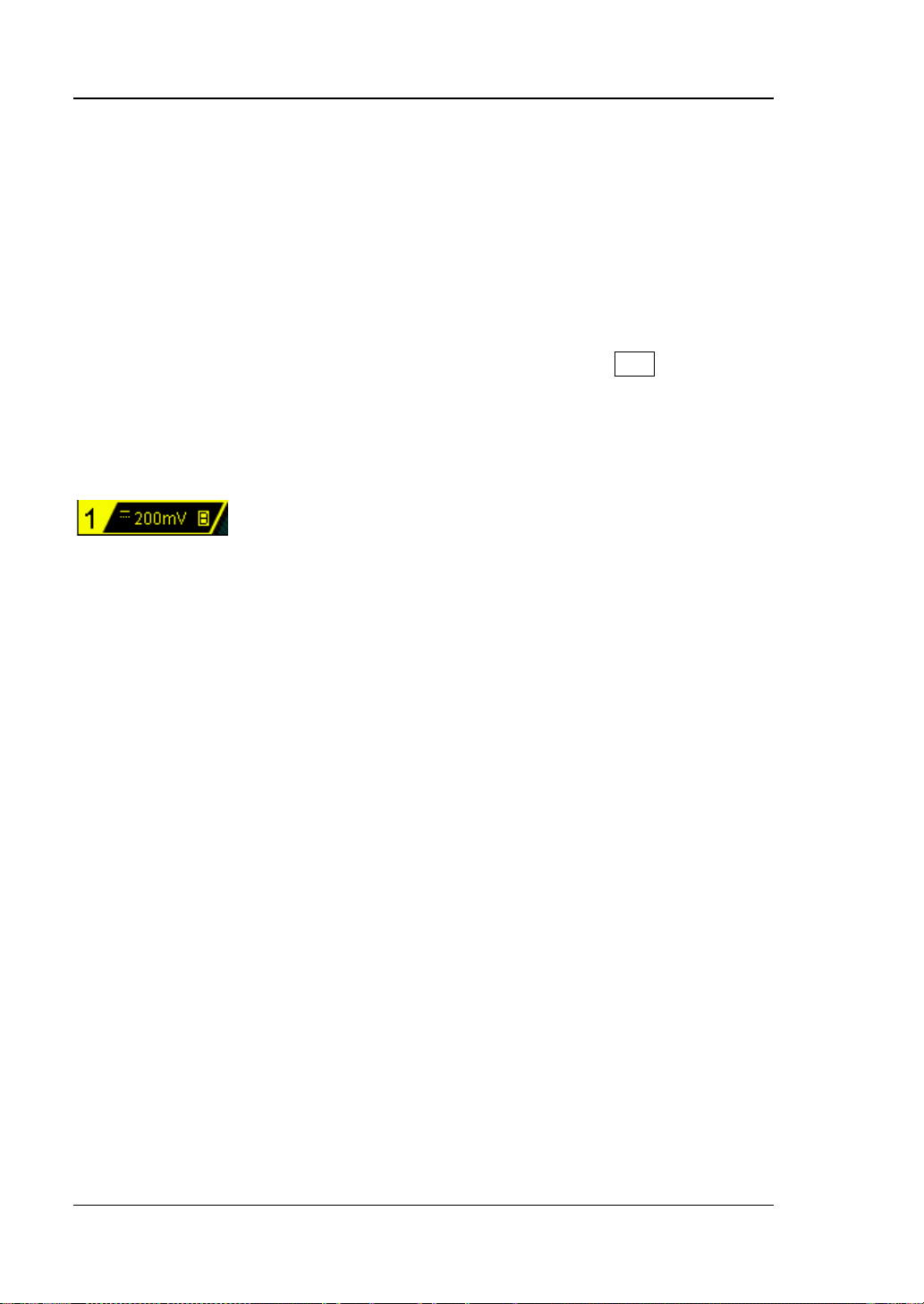
bottom of the screen (as shown in the figure below) is highlighted. The information
displayed in the channel label is related to the current channel setting.
After the channel is turned on, modify the para meters such as the vertical s c ale, the
horizontal time base, the trigger mode and the trigger level according to the input
signal to make the waveform displayed easy to observe and measure.
DS1000Z User’s Guide
Page 55

Chapter 2 To Set the Vertical System RIGOL
2-3
Channel Coupling
Set the coupling mode to f ilter out the undesired signals. For example, the signal
under test is a square waveform with DC offset.
When the coupling mode is “DC”: the DC and AC components of the signal under
test can both pass the channel.
When the coupling mode is “AC”: the DC components of the signal under test
are blo cked. The waveform displayed always takes the zero voltage as the
center.
When the coupling mode is “GND”: the DC and AC components of the signal
under test are both blocked.
Press CH1 Coupling and use to select the desired coupling mode (the
default is DC). The current coupling mode is displayed in the channel label at the
bottom of the screen. You can also press Coupling continuously to switch the
coupling mode.
DC AC GND
Bandwidth Limit
DS1000Z supports the bandwidth limit function. The bandwidth limit can reduce the
noise in the waveform displayed. For example, the signal under test is a pulse with
high frequency oscillation.
When bandwidth limit is disabled, the high frequenc y comp onents of the signal
under test can pass the channel.
Enable bandwidth limit and limit the bandwidth to 20 MHz, the high frequency
components that exceed 20 MHz are attenuated.
Press CH1 BW Limit and use to enable or disable bandwidth limit (the
default is OFF). When ban dwidth limit (20 MHz ) is e nabled, the char acter “B” will be
displayed in the channel label at the bottom of the screen. You can also press BW
DS1000Z User’s Guide
Page 56

RIGOL Chapter 2 To Set the Vertical System
2-4
Attenuation coefficient (signal
under test: waveform displayed)
0.01X
1000X
1:100
1000:1
Limit continuously to switch between on and off of the bandwidth limit.
Note: Although the bandwidth limit can reduce the noise, it will also attenuate or
eliminate the high-frequency components of the signal.
Probe Ratio
DS1000Z allows users to set the probe attenuation ratio manually. The probe ratio
values available are as shown in the table below.
Table 2-1 Probe Ratio
Menu
0.02X
0.05X
0.1X
0.2X
0.5X
1X
2X
5X
10X
20X
50X
100X
200X
500X
1:50
1:20
1:10
1:5
1:2
1:1
2:1
5:1
10:1
20:1
50:1
100:1
200:1
500:1
DS1000Z User’s Guide
Page 57

Chapter 2 To Set the Vertical System RIGOL
2-5
Waveform Invert
When waveform invert is enabled, the waveform display rotates 180 degree relative
to the ground potential. When waveform invert is disabled, the waveform display is
normal. Press CH1 Invert to enable or disable wave form invert.
Vertical Scale
The vertical scale refers to the voltage value per grid in the vertical direction on the
screen and is usually expressed in V/div. Adjusting the vertical scale will change the
size of the waveform displayed. The vertical scale can be adjusted in “Coarse” or
“Fine” mode.
Press CH1 Volts/Div to select the desired mode. Rotate VERTICAL SCALE
to adjust the vertical scale (clockwise to reduce the scale and counterclockwise to
increase).
The scale information (as shown in the figure below) in the channel label at the
bottom of the screen will change accordingly during the adjustment. The adjustable
rang e o f the vertical scale is related to the probe ratio currently set. By default, the
probe ratio is 10X and the adjustable range of the vertical scale is from 10 mV/div to
100 V/div.
Coarse adjustment (take counter clockwise a s an example): s et the v ertical s cale
in 1-2-5 step namely 1 mV/div, 2 mV/div, 5 mV/div, 10 mV/div…10 V/div.
Fine adjustment: further adjust the vertical scale within a relatively smaller
range to improve v e rtical r esolution. If the a mplitude of the input waveform is a
little bit greater than the full scale under the current scale and the amplitude
would be a little bit lower if the next scale is used, fine adjustment can be used
to improve the amplitude of waveform display to view signal details.
Note: You can also press VERTICAL
and “Fine” adjustments.
DS1000Z User’s Guide
SCALE to quickly switch between “Coarse”
Page 58

RIGOL Chapter 2 To Set the Vertical System
2-6
Vertical Expansion
When using VERTICAL
channel, you can choose to expand or compress the signal vertically around the
center of the screen or the ground point of the signal.
Press Utility System VerticalExp to select “Center” or “Ground” and the
default is “Ground”.
Center: when the vertical scale is modified, the waveform will expand or
compress around the center of the screen.
Ground: when the vertical scale is modified, the waveform ground level will
remain at the same point on the screen and the waveform will expand or
compress around this point.
SCALE to change the vertical scale of the analog
Amplitude Unit
Select the amplitude displ ay unit f or the cur rent channel. The av ailable units a re W, A,
V and U. When the unit is changed, the unit displayed in the channel label will
change accordingly.
Press CH1 Unit to select the desired unit and the default is V.
DS1000Z User’s Guide
Page 59

Chapter 2 To Set the Vertical System RIGOL
2-7
Channel Label
To identify different analog channels, you can set another label for each channel
(such as ). Press CH1 Label to enter the labe l setting menu, you can use
the built-in label or input the label manually and the length of the label inputted
manually cannot exceed 4 characters. Note: Only English lowercase input method
can be used for this operation.
Press Display to turn on or off the display of channel label and the default is CH1.
Press Label Edit to enable the label editing interface as shown in the figure below.
Name Input Area Keyboard Upper/Lower Case Switch
Figure 2-1 Label Editing Interface
For example, set the label to “
”.
Press Keyboard to select the “Keyboard” area. Select “Aa” using and press
down
to swi tch it to “aA”. Select “C” using and pres s do wn to input the
character. Use the same method to input “hn1”.
T o modif y or delete the input char acter, press Name to select the “Name Input Area”
and use
to select the character to be modified or deleted. Enter the desired
character or press Delete to delete the character selected.
After finishing the input, press OK to finish the modification. If Display is set to
“ON”, the label
will be displayed at the left of the CH1 waveform.
DS1000Z User’s Guide
Page 60
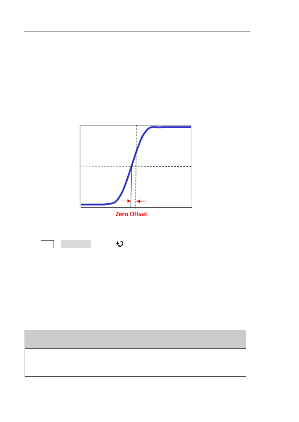
RIGOL Chapter 2 To Set the Vertical System
2-8
Horizontal Time
Delay Calibration
When using an oscilloscope for actual measurement, the transmission delay of the
probe cable may bring greater error (zero offset). DS1000Z allows users to set a
delay time to calibrate the zero offset of the corresponding channel. Zero offset is
defined as the offset of the crossing point of the waveform and trigg er level line
relative to the trigger position, as shown in the f igure below.
Figure 2-2 Zero Offset
Press CH1 Delay-Cal and use to set the desired delay time. The range
available is from -100 ns to 100 ns.
Note: This parameter is related to the instrument model and the horizontal time
base currently set. The greater the horizontal time base is, the greater the setting
step will be. Take DS1104Z as an example and the steps under different horizontal
time bases are as shown in the table below.
Table 2-2 Relation between the delay calibration step and horizontal time base
( DS1104Z)
Delay Calibration Time Step
Base
5ns 100ps
10ns 200ps
20ns 400ps
DS1000Z User’s Guide
Page 61

Chapter 2 To Set the Vertical System RIGOL
2-9
50ns 1ns
100ns 2ns
200ns 4ns
500ns 10ns
1μs and grater 20ns
DS1000Z User’s Guide
Page 62

Page 63

Chapter 3 To Set the Horizontal System RIGOL
3-1
Chapter 3 To Set the Horizontal System
The contents of this chapter:
Delayed Sweep
Time Base Mode
DS1000Z User’s Guide
Page 64

RIGOL Chapter 3 To Set the Horizontal System
3-2
Delayed Sweep
Delayed sweep can be use d to enla rge a len gth of w a v eform h orizontal ly t o view t he
waveform details.
Press MENU in the horizontal control area (HORIZONTAL) at the front panel and
press Delayed to enable or disable delayed sweep.
Note: To enable delayed sweep, the current time base mode must be “YT”.
DS1000Z User’s Guide
Page 65
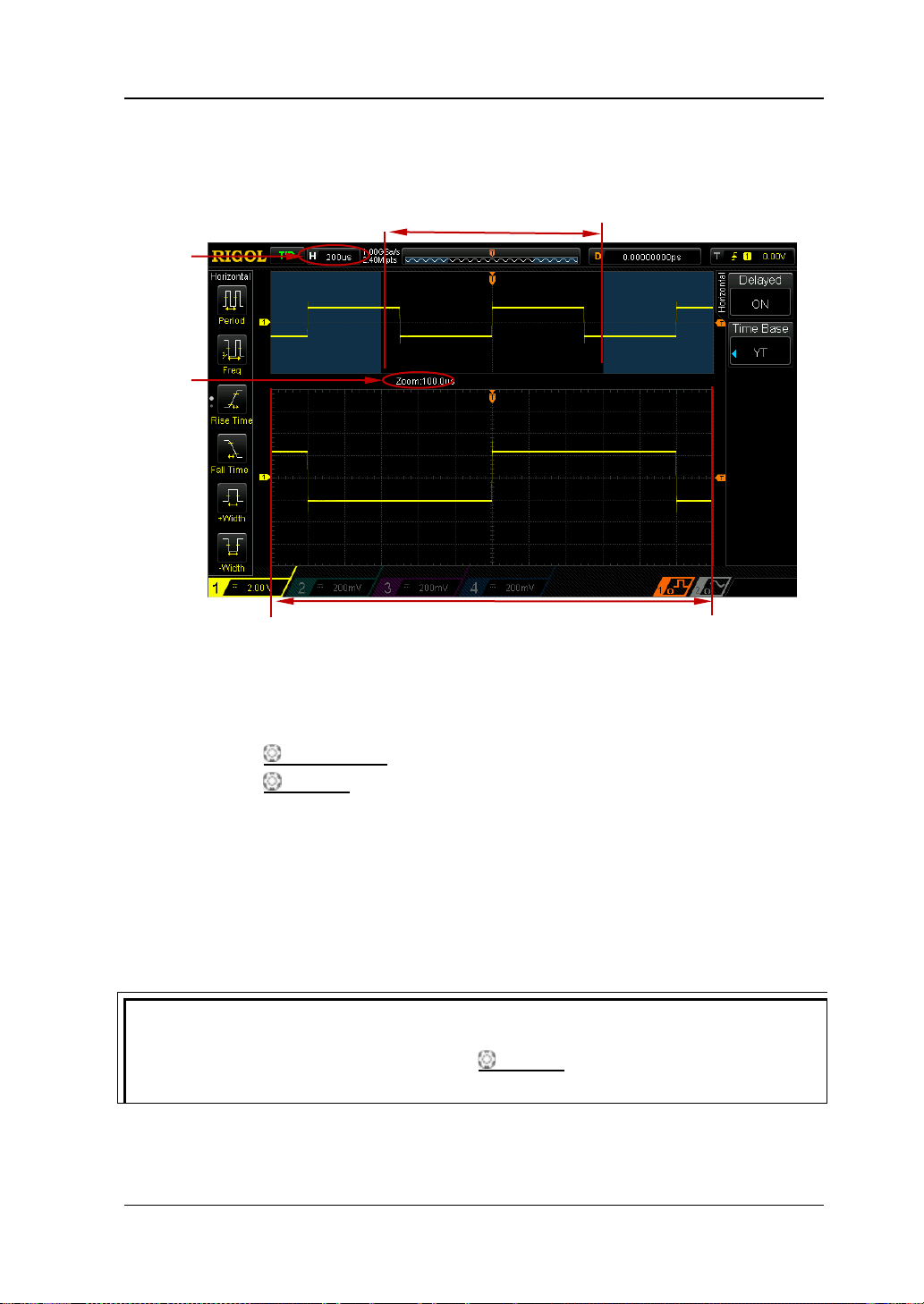
Chapter 3 To Set the Horizontal System RIGOL
3-3
Tip
Time Base
In delayed sweep mo de, t he s creen is divide d into t wo dis play a reas as show n in the
figure below.
Main time
base
The waveform before
enlargement
Delayed
Sweep
The waveform after enlargement
The waveform before enlargement:
The waveform in the area that has not been covered by the subtransparent blue in
the upper part of the screen is the waveform before enlargement. You can turn
HORIZONTAL
HORIZONTAL
POSITION to move the area left and right or turn
SCALE to enlarge or reduce this area.
The waveform after enlargement:
The waveform in the l ower part of the screen is the h orizontally expa nded wa veform.
Note: Compared to the main time base, the delayed time base has increased the
waveform resolution (as shown in the figure above). The delayed time base should
be less than or equal to the main time base.
You can also press down HORIZONTAL
SCALE (delayed sweep shortcut key)
to directly switch to delayed sweep mode.
DS1000Z User’s Guide
Page 66

RIGOL Chapter 3 To Set the Horizontal System
3-4
Time Base Mode
Press MENU in the horizontal control area (HORIZONTAL) at the front panel and
then press Time Base to select the time base mode of the oscilloscope and the
default is YT.
YT Mode
This mode is the main time base mode and is applicable to four input channels.
In this mode, the Y axis represents voltage and the X axis represents time.
Note: Only when this mode is enabled can “Delayed Sweep” be turn ed on.
DS1000Z User’s Guide
Page 67

Chapter 3 To Set the Horizontal System RIGOL
3-5
The signal must be
centered horizontally
XY Mode
In this mode, the oscilloscope changes the two channels from voltage-time display
mode to voltage -voltage display mode. The phase deviation between two signals
with the same frequency can be easily measured via Lissajous method. The figure
below shows the measurement schematic diagram of the phase deviation.
D
II I
II I
C
III IV
III IV
A
B
According to sin
the two channels and the definitions of A, B, C and D are as shown in the figure
above), the phase deviation angle is obtained, that is:
If the principal axis of the ellipse is within quadrant I and III, the phase deviation
angle obtained should be within quadr ant I an d IV, namely within (0 to π/2) or (3π/2
to 2π). If the principal axis of the ellipse is within quadrant II and IV, the phase
deviation angle obtained s hould be wit hin qua dr ant II an d II I, na mely within (π/2 to
π) or (π to 3π/2).
XY function can be used to measure the phase deviation occurred when the signal
under test passes through a ci rcuit network. Connect the oscilloscope to the ci rcuit to
monitor the input and output signals of the circuit.
DS1000Z User’s Guide
θ=A/B or C/D (wherein, θ is the phase deviation angle between
θ=±arcsin (A/B) or ±arcsin (C/D)
Page 68

RIGOL Chapter 3 To Set the Horizontal System
3-6
Application example: measure the phase deviation of the input signals of two
channels.
Method 1: Use Lissajous method
1. Co nnect a sine signal to CH1 and then connect a sine signal with the same
frequency and amplitude but a 90° phase deviation to CH2.
2. Press AUTO and adju st the vertical position of CH1 and CH2 to 0.
3. Press X-Y to selec t “CH1-CH2”, rotate Horizontal SCALE to ajdut the
sample rate properly to get better Lissajous fig ure for better observation and
measurement.
4. Roate VERTICAL POSITION to adju s t CH1 and CH2 to get better
observation of signals. At this point, the circle as shown in the figure below
should be displayed.
5. As shown in the figure above, the distances from th e crossing points of axis and
the circle to the origin of the coordinates are approximately equal. Thus, the
phase deviation angle
θ=±arcsin1=90°.
Note:
In YT mode, the oscilloscope could use any sample rate (within the guaranteed
range) to capture waveform. The maximum sample rate of XY mode is 500
MSa/s. Generally, reducing the sample rate properly could improve the display
effect of Lissajous figure.
When XY mode is enabled, “Delayed Sweep” will be disabled automatically.
Press X-Y to select “CH1-CH2, CH1-CH3, CH1-CH4, CH2-CH3, CH2-CH4,
DS1000Z User’s Guide
Page 69

Chapter 3 To Set the Horizontal System RIGOL
3-7
CH3-CH4” and the two channels corresponding will be enabled automatically
and disabled the other t wo channels at the same time. X axis traces the voltage
of the later channel of each option and Y axis traces the voltage of the forme r
channel of each option.
The following functions are not available in XY mode:
Auto measure, cursor measure, math operation, reference waveform, delayed
sweep, vector display, HORIZONTAL
POSITION, trigger con trol, memory
depth, acquisition mode, Pass/Fail test and waveform record.
Method 2: Use the shortcut measurement function
Please refer to “Phase A→B ” and “Phase A→B ” measurement f un ctions of “Delay
and Phase” on page 6-63.
DS1000Z User’s Guide
Page 70

RIGOL Chapter 3 To Set the Horizontal System
3-8
Slow Sweep
Roll Mode
In this mode, the waveform scrolls from the right to the left to update the display and
the waveform horizontal position and trig ger control are not available. The range of
horizontal scale adjustment is from 200.0 ms to 50 s.
Note: When Roll mode is enabled, the “horizontal position”, “Delayed Sweep”,
“Protocol Decoding”, “Pass/Fail Test”, “Waveform Record”, “To Set the Persistence
Time” and “To Trigger the Oscilloscope” are not available.
Another mode similar to Roll mode. When the horizontal time base is set to 200
ms/div or slower, the instrument enters “slow sweep” mode in which t he instrument
first acquires the data at the left of the trigger point and then waits for trigger
event. After the trigger occurs, the instrument continues to finish the waveform at
the right of the trigger point. When slow sweep mode is used to observe low
frequency signal, it is recommended that the “Channel Coupling” is set to “DC”.
DS1000Z User’s Guide
Page 71

Chapter 4 To Set the Sample System RIGOL
4-1
Chapter 4 To Set the Sample System
The contents of this chapter:
Acquisition Mode
Sin(x)/x
Sample Rate
Memory Depth
Antialiasing
DS1000Z User’s Guide
Page 72

RIGOL Chapter 4 To Set the Sample System
4-2
Acquisition Mode
The acquisition mode is used to control how to generate waveform points from
sample points.
Press Acquire Mode in the function menu at the front panel and use to
select the desired acquisition mode (the default is normal), then press down the
knob to select this mode. You can also press Mode continuously to switch the
acquisition mode.
Normal
In this mode, the oscilloscope sam ples the signal at equal time int erval to re build th e
waveform. For most of the waveforms, the best display effect can be obtained using
this mode.
Average
In this mode, the oscilloscope averages the waveforms from multiple samples to
reduce the rand om noise of the input signal and improve t he vertical resolution. The
greater the number of ave rages is, the lower the noise will be and the higher the
vertic al resolution will be but the slower the response of the displayed waveform to
the waveform changes will be.
The available ran ge of the number of ave rages is from 2 to 1024 a nd the def ault is 2.
When “Average” mode is selected, press Averages and use to set the desired
number o f averages as the power function of 2.
DS1000Z User’s Guide
Page 73
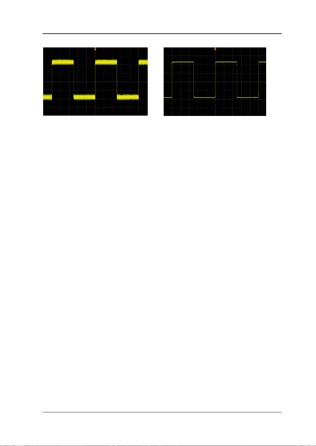
Chapter 4 To Set the Sample System RIGOL
4-3
(a) The Waveform before Average ( b) The Waveform after 256 Averages
Figure 4-1 Average Acquisition Mode Example
Peak Detect
In this mode, the oscilloscope acquires the maximum and minimum values of the
signal within the sample in terval to get the envel ope of the signal or the narrow pulse
of the signal that might be lost. In this mo de, signal confusion can be prevented but
the noise displayed would be larger.
In this mode, the oscilloscope can display all the pulses with pulse w idths at least as
wide as the sample period.
High Resolution
This mode uses a kind of ultra-sample technique to average the neighboring points
of the sample w aveform to reduce the random n oise on the input signal a nd generate
much smoother waveforms on the screen. This is generally used when the sample
rate of the digital converter is hi gher than the st orage r ate of the a cquisition memory.
Note: “Average” and “High Res” modes use different averaging methods. The
former uses “multiple sample average” and the latter uses “signle sample average”.
DS1000Z User’s Guide
Page 74
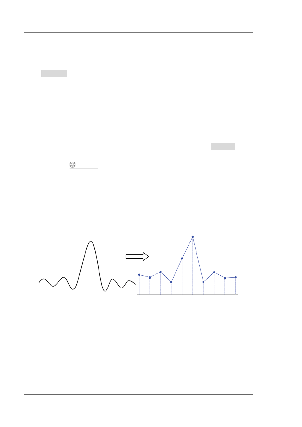
RIGOL Chapter 4 To Set the Sample System
4-4
Sin(x)/x
Press Sin(x)/x to enable or disable the dynamic sine interpolation function. Enable
the dynamic sine interpolation can restore the original wavefor m m ore real.
Sample Rate
The sample rate of this oscilloscope is up to 1 GSa/s. Note: the sample rate is
displayed in the status bar at the upper side of the screen and in the Sa Rate menu
and can be changed by adjusting the horizontal time base (s/div) through
HORIZONTAL
The influence on the waveform when the sample rate is too low:
1. Waveform Distortion: when the sample rate is too low, some waveform
details are lost and the waveform displayed is r at her diff erent from the actual
signal.
SCALE or modifying the memory depth.
2. Waveform Confusion: when the sample rate is lower than twice the actual
signal frequency (Nyquist Frequency), the frequency of the waveform rebuilt
from the sample data is lower than the actual signal frequency. The most
common aliasing is the jitter on fast edge.
DS1000Z User’s Guide
Page 75

Chapter 4 To Set the Sample System RIGOL
4-5
3. Waveform Leakage: when the sample rate is too low, the waveform rebuilt
from the sample data does not reflect all the actual signal information.
Pulse
disappeared
DS1000Z User’s Guide
Page 76
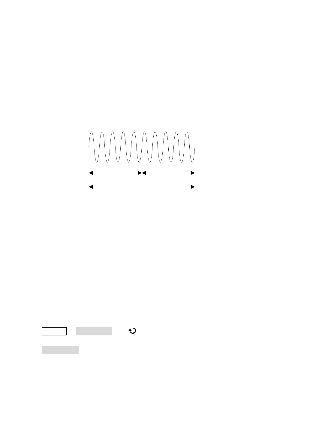
RIGOL Chapter 4 To Set the Sample System
4-6
T
Trigger Point
Pre-sample
Delayed Sample
Memory Depth
MDepth SRate TScale HDivs
=××
MDepth
SRate
TScale
HDivs
Memory Depth
Memory depth refers to the number of w aveform poi n t s th at the oscilloscope can
store in a single trigger sample and it reflects the storage ability of the sample
memory. DS1000Z provides up to 24 Mpts memory depth (option) and 12 Mpts
standard memory depth.
Figure 4-2 Memory Depth Schematic Diagram
The relation of the memory depth, sample rate and horizontal time base s cale fulfills
the equation below. Therefore, under the same horizontal time base scale, higher
memory depth can ensure higher sample rate.
Wherein,
——memory depth, the unit is pts
—sample rate, the unit is Sa/s
——horizontal time base scale, the unit is s/div
——the number of grids in the horizontal direction of the screen, the unit is
div. For DS1000Z, this value is 12.
Press Acquire Mem Dept h, use to switch to the desired memory depth (the
default is auto) and then press down the knob to select the option. You can also
press Mem Depth continuously to switch the memory depth.
When a single channel is enabled, the memory depths available include Auto,
12kPoints, 120kPoints, 1200kPoints, 12MPoints and 24MPoints (optional). In “Auto”
mode, the oscilloscope selects the memory depth automatically according to the
DS1000Z User’s Guide
Page 77

Chapter 4 To Set the Sample System RIGOL
4-7
current sample rate.
When two channels are enabled , the memory depths available in clude Auto, 6kPoints,
60kPoints, 600kPoints, 6MPoints and 12MPoints (optional). In “Auto” mode, the
oscilloscope selects the memory depth aut omatically a ccording to the current sample
rate.
When four channels are enabled, the memory depths a vailable include Auto,
3kPoints, 30kPoints, 300kPoints, 3MPoints and 6MPoints (optional). In “Auto” mode,
the oscilloscope selects the memory depth automatically according to the current
sample rate.
Antialiasing
At slower sweep speed, the sample rate is reduced and a dedicated display al gorithm
is used to minimize the possibility of aliasing.
Press Acquire Anti_Aliasing to enable or disable the antialiasing function. By
default, antialiasing is disa bled. The dis played wa veforms w ill be mo re susceptible to
aliasing when this function is disabled.
DS1000Z User’s Guide
Page 78

Page 79

Chapter 6 To Make Measurements RIGOL
5-1
Chapter 5 To Trigger the Oscilloscope
For trigger, you set certain trigger condition according to the requirement and when
a waveform in the waveform stream meets this condition, the oscilloscope captures
this waveform as well as the nei ghbourin g pa rt and displa ys t he m on the s creen. For
digital oscilloscope, it displays waveform continuously no matter whether it is stably
triggered, bu t only stable trigger can ensure st able display. The trigger circuit
ensures that every time base sweep or acquisition starts from the input signal and
the user-defined trigger condition, namely every sweep is synchronous to the
acquisition and the waveforms acquired overlap to display stable waveform.
Trigger setting should be based on the features of the input signal, thus you need to
have some knowledge of the signal under test to quickly capture the desired
waveform. This os cilloscope provides abundant adv anced trigger f unctions which can
help you to focus on t he desired waveform details.
The contents of this chapter:
Trigger Source
Trigger Mode
Trigger Coupling
Trigger Holdoff
Noise Rejection
Trigger Type
Trigger Output Connector
DS1000Z User’s Guide
Page 80

RIGOL Chapter 6 To Make Measurements
5-2
Trigger Source
Press MENU Source in the trigger control area (TRIGGER) at the front panel to
select the desired trig ger sou rce. Siganls input from CH1-CH4 and AC can all be used
as trigger source.
Analog channel input (CH1 to CH4):
Signals input from analog channels CH1-CH4 can all be used as the trigger source.
No matter whether the input of the channel selected is enabled, the channel can
work normally.
AC:
The trigger signal is obtai n e d from the AC pow e r input of the oscilloscope. This kind
of signals can be us ed to display the relationship between signal (such as illuminating
device) and pow er (power suppl y device). For example, to stably tr igger the
waveform output from the transformer of a transformer sub s t a ti on , which is mainly
used in related measurement of the power industry.
DS1000Z User’s Guide
Page 81

Chapter 6 To Make Measurements RIGOL
5-3
Trigger Mode
Trigger mode affects the way in which the oscilloscope searches for the trigger. Th e
following is the s chematic diagra m of the a cquisition memory. As shown in the figure
below, the position of the trigger event is determined by the reference time point and
the delay setting. Note that the acquisition memory of the oscilloscope is a cyclic
buffer and the new data would overwrite the old data until the acquisition finishes.
Pre-trigger Buffer Post-trigger Buffer
Acquisition memory
Figure 5-1 Acquisition Memory Schematic Diagram
Pre-trigger/Delayed trigger:
Acquire data before/after the trigger event. The trigger position is usually at the
horizontal center of the screen. In full-screen display, six-grid pre-trigger and delayed
trigger information are displaye d respe ctiv e ly. You can adjust the horizontal position
of the waveform through HORIZONTAL
information and delayed trigger information, through which the signal information
before/after the trigger (such as capture the glitch generated by the circuit and
analyze the pre-trigger data to find out the reasons for glitch) can be obtained.
Press MODE in the trigger control area (TRIGGER) at the front panel or press
MENU Sweep to select the desired trigger mode. The corresponding s tatu s li ght
of the mode currently selected turns on.
Auto:
No matter whether the trigger condition is met, there is always waveform display. A
horizontal line is displayed when no signal is input.
In this mode, the oscilloscope operates by first filling the pre-trigger buffe r. It starts
searching for a trigger after the pre-trigger buffer i s filled and continues to flow dat a
Trigger Event
POSITION to vi e w more pr e -trigger
DS1000Z User’s Guide
Page 82

RIGOL Chapter 6 To Make Measurements
5-4
through this buffer while it searches for the trigger. While searching for the trigger,
the oscilloscope overflows the pre-trigger buff er and the first data put into the buffer
is first pushed out (First Input First Out, FIFO). When a trigger is found, the
pre-trigger buffer would contain the data acquired just before the trigger. If no
trigger is found, the oscilloscope will t rigger forcef ully. If fo rceful trigger is invali d, the
oscilloscope still displays w a vef orm but the w av ef orm is not sta ble; if forceful trigger
is valid, the oscilloscope displays stable waveform.
This trigger mode is applicable to low-repetitive-rate signals and unknown signal
levels. To display DC signals, you must use auto trigger mode.
Note: When the horizontal time base is set to 50 ms/div or greater, this trigger mode
allows the absence of trigger signal.
Normal:
Display waveform when the trigger condition is met; otherwise, the oscilloscope
holds the original waveform and waits for the next trigger.
In this mode, the oscilloscope fills the pre-trigger buffer fir s t and the n search for a
trigger while at the same time continues filling data. While searching for the trigger,
the oscilloscope overflows the pre-trigger buff er and the first data put into the buffer
is first pushed out (FIFO). When a trigger is found, the oscilloscope will fill the
post-trigger buffer and display the a cquisitio n mem o ry.
Use normal trigger mode for low-repetitive-rate signals or when auto trigger is not
required.
Single:
When this mode is selected, the backlight of SINGLE turns on. The oscilloscope
waits for a trigger and displays the waveform when the trigger condition is met and
then stops.
DS1000Z User’s Guide
Page 83

Chapter 6 To Make Measurements RIGOL
5-5
Trigger Coupling
Trigger coupling decides which kind of components will be transmitted to the trigger
circuit. Please distinguish it with “Channel Coupling”.
DC: allow DC and AC components into the trigger path.
AC: block all the DC components and attenuate signals lower than 75 kHz.
LF Reject: block the DC components and reject the low frequency components
(lower than 75 kHz).
HF Reject: reject the high frequency components (higher than 75 kHz).
Press MENU Setting Coupling in the trigger control area (TRIGGER) at the
front panel to select the desired coupling type (the default is DC). Note that trigger
coupling is only valid in edge trigger.
DS1000Z User’s Guide
Page 84

RIGOL Chapter 6 To Make Measurements
5-6
Trigger
Positions
Trigger Holdoff
Trigger holdoff can be used to stably trigger the complex waveforms (such as pulse
series). Holdoff time is the amount of time that the oscilloscope waits before
re-arming the trigger circuitry. The oscilloscope will not trigger until the holdoff time
expires.
Trigger Holdoff Time
Figure 5-2 Trigger Holdoff
Press MENU Setting Holdoff in the trigger control area (TRIGGER) at the
front panel and use to modify the holdoff time (the default is 16 ns) until the
wavef orm tri g gers s ta bl y. The adjustable range of hold of f ti me is f ro m 1 6 ns to 10 s.
Note that trigger holdoff is not available for vi deo trigger.
DS1000Z User’s Guide
Page 85

Chapter 6 To Make Measurements RIGOL
5-7
Noise Rejection
Noise rejection reduces the possibility of noise trigger.
Press MENU Setting Noise Reject in the trigg er control area (TRIGGER) at
the front panel to enable or disable noise rejection.
DS1000Z User’s Guide
Page 86

RIGOL Chapter 6 To Make Measurements
5-8
Trigger Type
DS1000Z provides various trigger functions, including various serial bus triggers.
Edge Trigger
Pulse Trigger
Slope Trigger
Video Trigger
Pattern Trigger
Duration Trigger
Setup/Hold Trigger (Option)
TimeOut Trigger (Option)
Runt Trigger (Option)
Windows Trigger (Option)
Delay Trigger (Option)
Nth Edge Trigger (Option)
RS232 Trigger (Option)
I2C Trigger (Option)
SPI Trigger (Option)
DS1000Z User’s Guide
Page 87
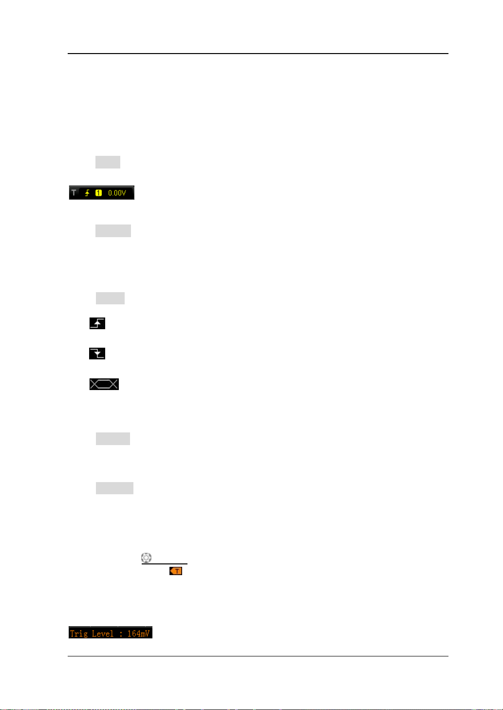
Chapter 6 To Make Measurements RIGOL
5-9
Edge Trigger
Trigger on the trigger level of the specified edge of the input signal.
Trigger Type:
Press Type to select “Edge”. At this point, the trig ger setting inf ormation as shown i n
the fi g ure below is displayed at the upper right corner of the screen.
Source Selection:
Press Source to select CH1-CH4 or AC as the “Trigger Source”. The current trigger
source is displayed at the upper right corner of the screen.
Note: Select channel with signal input as trigger source to obtain stable trigger.
Edge Type:
Press Slope to select the kind of edge of the input signal on which the oscilloscope
triggers. The current edge type is displayed at the upper right corner of the screen.
: trigger on the rising edge of the input signal when the voltage level meets
the preset trigger level.
Trigger Mode:
Press Sweep to select the “Trigger Mode” under this trigger type as auto, normal
or single. The corresponding status light of the current trigger mode turns on.
Trigger Setting:
Press Setting to set the trigger p aramete r s ( trigger coupling, trigg er hol doff and
noise rejection) under this trigger type.
Trigger Level:
Trigger occurs only when the signal reaches the preset trigger level.
Use TRIGGER
and the t rigger mark “
rotation of the knob, while at t he sa me time , the trig ger leve l v alue (as shown in the
figure below) at the lower left corner of the screen also changes accordingly. When
stopping turning the knob, the trigger level line and the trigger mark disappear in
abou t 2 s.
: trigger on the f a lling edge of the input si gnal when the voltage level meets
the preset trigger level.
: trigger on t he rising or falling edges of the input si gnal when the v oltage
level meets the preset trigger level.
LEVEL to modify the trigger level. An orange trigger level line
” appear on the scr een and move up and d own with th e
DS1000Z User’s Guide
Page 88
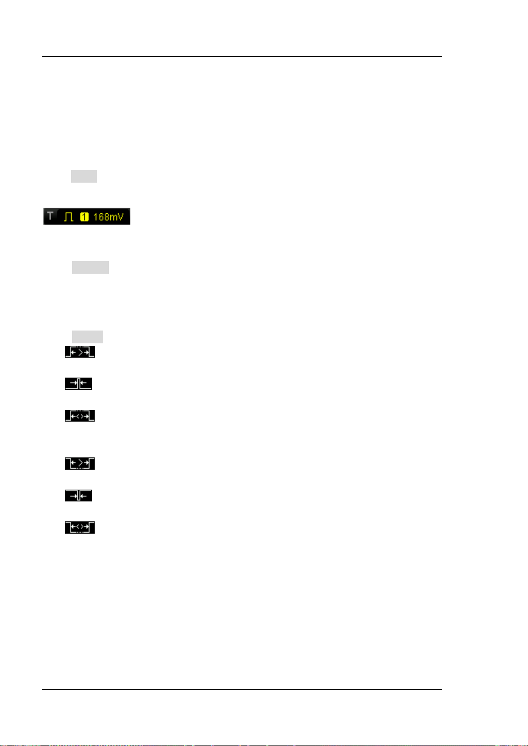
RIGOL Chapter 6 To Make Measurements
5-10
Pulse Trigger
Trigger on the positive or negative pulse with a specified width.
Trigger Type:
Press Type to select “Pulse”. At this point, t he trigger setting information as shown in
the fi g ure below is displayed at the upper right corner of the screen.
Source Selection:
Press Source to select CH1-CH4 as the “Trigger Source”. The current tri gger
source is displayed at the upper right corner of the screen.
Note: Select channel with signal input as trigger source to obtain stable trigger.
Pulse Condition:
Press When to select the desired pulse condition.
: trigger when the positive pulse width of the input signal is greater than
the specified pulse width.
Pulse Width Setting:
As shown in t he figure below, positive pulse width is def ined as the time difference
between the two crossing points of the trigger level and positive pulse and negative
pulse width is defined as the time difference between the two crossing points of the
trigger level and negative pulse.
: trigger when the positive pulse wi dth of the input si gnal is lower than the
specified pulse width.
: trigger when the positive pulse width of the input signal is greater than
the specified lower limit of pulse width and lower than the upper limit of pulse
width.
: trigger when the negativ e pulse width of the input signal is greater than
the specified pulse width.
: trigger when the negative pulse width of the input signal is lower than
the specified pulse width.
: trigger when the negativ e pulse width of the input signal is greater than
the specified lower limit of pulse width and lower than the upper limit of pulse
width.
DS1000Z User’s Guide
Page 89

Chapter 6 To Make Measurements RIGOL
5-11
Width
Pulse Width
A
Positive Pulse
Negative
A
B
Trigger Level
B
Trigger Level
Figure 5-3 Positive Pulse Width/Negativ e Pulse Width
When the Pulse Condition is set to
, , or , press
Setting and use to input the desired v alue. The range av ailable is fr om 8 ns
to 10 s.
When the Pulse Condition is set to or , press Upper Limit and
Lower Limit and use to input the desired v alues respectively. The range of
the upper limit is f rom 16 ns to 10 s. The range of the lowe r limit is fro m 8 ns to
9.99 s. Note that the lower limit of t he pulse width must be lower than the upper
limit.
Trigger Mode:
Press Sweep to select the “Trigger Mode” under this trigger type as auto, normal
or single. The corresponding status light of the current trigger mode turns on.
Trigger Setting:
Press Setting to set the trigger parameters (trigger holdoff and noise rejection)
under this trigger type.
Trigger Level:
Use TRIGGER LEVEL to modify the level. For details, please refer to the
description of “
Trigger Level” on page 5-9.
DS1000Z User’s Guide
Page 90

RIGOL Chapter 6 To Make Measurements
5-12
Slope Trigger
Trigger on the positive or negative slope of specified time.
Trigger Type:
Press Type to select “Slope”. At this point, the trigger setting information as shown
in the figure below is displayed at the upper right corner of the screen.
Source Selection:
Press Source to select CH1-CH4 as the “Trigger Source”. The current trigger
source is displayed at the upper right corner of the screen.
Note: Select channel with signal input as trigger source to obtain stable trigger.
Slope Condition:
Press When to select the desired slope condition.
: trigger when the positive slope time of the input signal is greater than
the specified time.
specif ied time.
: trigger when the positive slope time of the input signal is greater than
the specified lower limit of time and lower than the specified upper limit of time.
the specified time.
the specified time.
the specified lower limit of time and lower than the specified upper limit of time.
: trigger when the positive slope time of the i nput signal is lower than the
: trigger when the ne gativ e slope time of the inp ut si gnal is great er than
: trigger when the negative slope time of the input signal is lower than
: trigger when the ne gativ e slope time of the inp ut si gnal is great er than
DS1000Z User’s Guide
Page 91

Chapter 6 To Make Measurements RIGOL
5-13
A
Positive
Negative
Time Setting:
As shown in t he figure below, positive slope time is defined as the time difference
between the two crossing points of trigger level upper limit and lower limit with the
positive edge and negative slope time is defined as the time difference between the
two crossin g points of trigger level u pper limit and l ower limit with t he negative edge .
B
The upper limit of trigger level (Up Level)
The lower limit of trigger level (Low Level)
Slope time
Slope time
Figure 5-4 Positive Slope Time/Negativ e Slope Time
When the Slope Condition is set to
, , or ,
press Time and use to input the desired value. The range a vailable is from 8
ns to 10 s.
When the Slope Condition is set to or , press Upper Limit
and Lower Limit and use to input the desired values respectively. The
range of time upper limit i s from 16 ns to 10 s. The r ange of the time lower limi t
is from 8 ns to 9.99 s. Note that the time lower limit must be lower than the
upper limit.
Vertical Window:
Press Vertical to select the desired vertical window and then use TRIGGER
LEVEL to adjust the trigger level. During the adjustment, two orange trigger level
lines and two trigger marks (
and ) appear on th e screen and m ove up and
down with the rotation of the knob, while at the same time, the trigger level value
and the slope value are displayed at the lower left corner of the screen. When
stopping turning the knob, the trigger level lines and trigger marks disappear in
about 2 s.
When the Slope Condition is set to
, , or , the
current trigger level and sl ope will be displayed at the lower left corner of the screen,
as shown in figure (a). The slope calculation formula is:
DS1000Z User’s Guide
Page 92
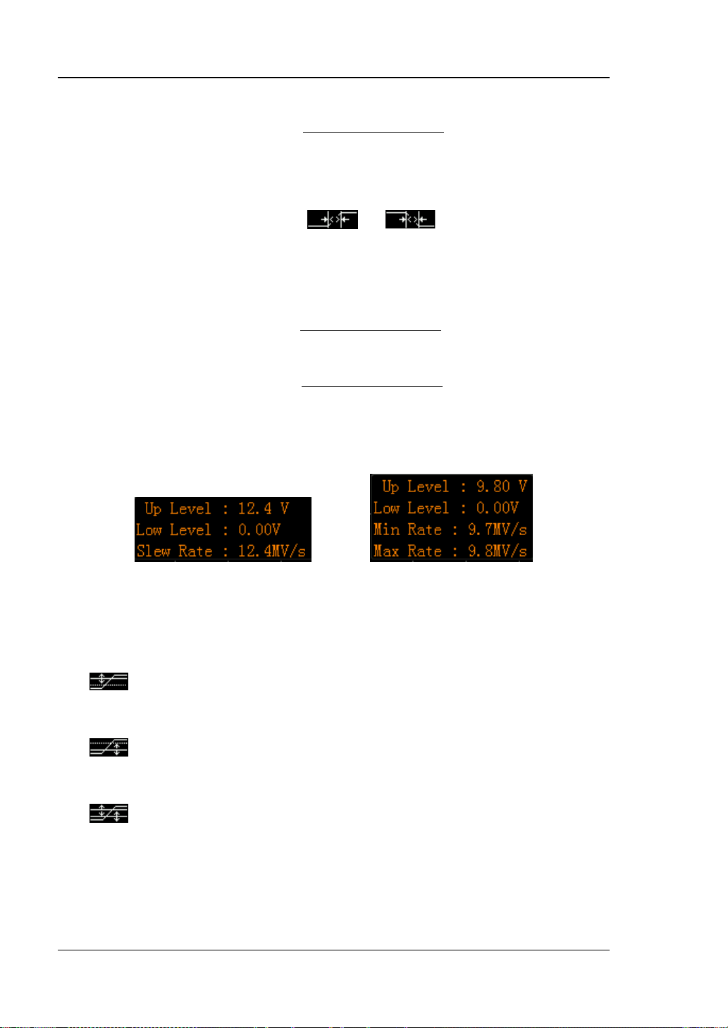
RIGOL Chapter 6 To Make Measurements
5-14
UpLevel LowLevel
SlewRate
TimeSetting
−
=
TimeSetting
UpLevel LowLevel
MinRate
UpTime
−
=
UpLevel LowLevel
MaxRate
LowTime
−
=
UpTime
LowTime
Wherein,
When the Slope Condition is set to
minimum slope and maximum slope will be displayed at the lower left corner of the
screen, as shown in figure (b). The caculation formulas of the minimum slope and
maximu m s lope are:
Wherein,
currently set.
The adjustment mode of the trigger level is different when different vertical window
is selected.
Note: Under the “Slope” trigger menu, you can also press down the trigger level
knob continuously to switch the vertical window.
: only adjust the upper limit of the trigger level. During the adjustment,
“UP Level” and “Slew Rate ” change accordingly but “Low Level” remains
unchanged.
: only adjust the lower limit of th e trigg er level. During the adjustment,
“Low Level” and “Slew Rate” change accordingly but “UP Level” remains
unchanged.
: adjus t the upper and lower limits of the trigger level at the same time.
During the adjustment, “UP Level” and “Low Level” change accordingly but
“Slew Rate” remains unchanged.
is the time currentl y set.
or , the current trigger level ,
and
Figure (a) Figure (b)
Figure 5-5 Trigger Level and Slope
are the time upper limit and time lower limit
DS1000Z User’s Guide
Page 93

Chapter 6 To Make Measurements RIGOL
5-15
Trigger Mode:
Press Sweep to select the “Trigger Mode” under this trigger type as auto, normal
or single. The corresponding status light of the current trigger mode turns on.
Trigger Setting:
Press Setting to set the trigger parameters (trigger holdoff and noise rejection)
under this trigger type.
DS1000Z User’s Guide
Page 94

RIGOL Chapter 6 To Make Measurements
5-16
Video Trigger
Trigger on the specified standard video signal field or line.
Trigger Type:
Press Type to select “Video”. At this point, the trigger setting information as shown
in the figure below is displayed at the upper right corner of the screen.
Source Selection:
Press Source to select CH1-CH4 as the “Trigger Source”. The current trigger
source is displayed at the upper right corner of the screen.
Note: Select channel with signal input as trigger source to obtain stable trigger.
Video Polarity:
Press Polarity to sele ct the desire d video polarit y . The polarities a vailable are normal
polarity (
Sync:
Press Sync to select the desired sync type.
All Lines: trigger on all the horizontal sync pulses.
Line Num: for NTSC and PAL/SECAM video standards, trigger on the specified
line in the odd or even field; for HDTV video standard, trigger on the specified
line. Note that when this sync trigger mode is selected, you can modify the line
number using in the Line Num menu with a step of 1. The range of the line
number is from 1 to 525 (NTSC), 1 to 62 5 ( PAL/SECAM), 1 t o 5 25 (480P), 1 to
625 (576P).
Odd field: trigger on the rising edge of the first ramp w avef orm pulse in the odd
field.
Even field: trigger on the rising edge of the f ir st ramp waveform pulse in the
even fiel d.
Video Standard:
Press Standard to select the desired video standard.
NTSC: the field frequency is 60 fields per second a nd the frame f reque nc y is 30
frames per second. The TV sweep line is 525 with the even field goes first and
the odd field follows behind.
PAL: the frame frequency is 25 fr a mes per s econd. The TV sweep line is 625
with the odd field goes first and the even field follows behind.
SECAM: the frame frequency is 25 frames per second. The sweep line is 625
) and inverted polarity ( ).
DS1000Z User’s Guide
Page 95

Chapter 6 To Make Measurements RIGOL
5-17
with interlacing sweep.
480P: the frame frequency is 60 frames per second; the TV sweep line is 525;
line-by-line sweep; the line frequency is 31.5 kHz.
576P: the frame frequency is 60 frames per second; the TV sweep line is 625;
line-by-line sweep.
Trigger Mode:
Press Sweep to select the “Trigger Mode” under this trigger type as auto, normal
or single. The corresponding status light of the current trigger mode turns on.
Trigger Setting:
Press Setting to set the trigger parameter (noise rejection) under this trigger type.
Trigger Level:
Use TRIGGER LEVEL to modify the level. For details, please refer to the
description of “
Trigger Level” on page 5-9.
DS1000Z User’s Guide
Page 96

RIGOL Chapter 6 To Make Measurements
5-18
Pattern Trigger
Identify a trigger condition by lookin g for a specified pattern. This pattern is a logi cal
“AND” combination of the valuesof the four channels. Each channel can have a value
of high (H), low (L) or don ’t care ( X) . A ris ing o r fall ing edge can be s pecif ied f or one
channel included in the pattern. When an edge is specified, the oscilloscope will
trigger at the edge specified if the pattern set for the other channel is true (H or L). If
no edge is specified, the oscilloscope will trigger on the last edge that makes the
pattern true. If both the channels in the pattern are set to “Don’t Care”, the
oscilloscope will not trigger.
Figure 5-6 Pattern Trigger Schematic Diagram
Trigger Type:
Press Type to select “Pattern”. At this point, the trigger setting information as shown
in the figure below is displayed at the upper right corner of the screen.
Channel Selection:
Press Source to select CH1-CH4 respectively. The current signal source is displayed
at the upper right corner of the screen.
Pattern Setting:
Press Code to set the pattern of the current channel. At this point, the pattern
setting area (as sh own in the figure below) is displayed at the bottom of the screen.
: set the pattern of the channel selected to “H”, namely the voltage level is
higher than the trigger level of the channel.
: set the pattern of the channel selected to “L”, namely the voltage level is
lower than the trigger level of the channel.
DS1000Z User’s Guide
Page 97
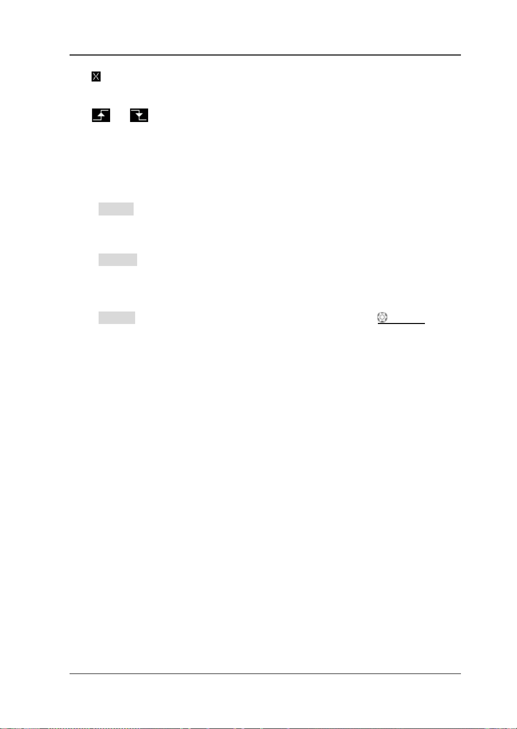
Chapter 6 To Make Measurements RIGOL
5-19
: set the pattern of the channel selected to “Don’t Care”, namely this channel is
not used as a part of the pattern. When both the channels in the pattern a re set
to “Don’t Care”, the oscilloscope will not trigger.
or : set the pattern t o the rising or fallin g edge of t he channel selected.
Note: Only one rising or falling edge can be specified in the pattern. If one edge
item is currently defined and then anothe r edge item is define d in another chan nel in
the pattern, the former edge item defined will be replaced by X.
Trigger Mode:
Press Sweep to select the “Trigger Mode” under this trigger type as auto, normal
or single. The corresponding status light of the current trigger mode turns on.
Trigger Setting:
Press Setting to set the trigger parameters (trigger holdoff and noise rejection)
under this trigger type.
Trigger Level:
Press Source to select CH1-CH4 respectively and use TRIGGER LEVEL to set
the trigger level of each channel. For details, please refer to the description of
“
Trigger Level” on page 5-9.
DS1000Z User’s Guide
Page 98

RIGOL Chapter 6 To Make Measurements
5-20
Duration Trigge r
Identify a trigger condition by looking for the duration of a specified pattern. This
pattern is a logical “AND” combination of the four channels. Each channel can have a
value of high (H), low (L) or don’t care (X). The instrument triggers when the
duration (△T) of this pattern meets the preset time, as shown in the figure below.
Figure 5-7 Duration Trigger Schematic Diagram
Trigger Type:
Press Type to select “Duration”. At this point, the trigger setting information as
shown in the figure below is displayed at the upper right corner of the screen.
Source Selection:
Press Source to select CH1-CH4 respectively. The current signal source is displayed
at the upper right corner of the screen.
DS1000Z User’s Guide
Page 99

Chapter 6 To Make Measurements RIGOL
5-21
Pattern Setting:
Press Code to set the pattern of the current channel. At this point, the pattern
setting area (as sh own in the figure below) is displayed at the bottom of the screen.
: set the pattern of the channel selected to “H”, namely the voltage level is
higher than the trigger level of the channel.
: set the pattern of the channel selected to “L”, namely the voltage level is
lower than the trigger level of the channel.
: set the pattern of t he channel selected to “Don’t Care”, namely this channel is
not used as a part of the pattern. When both the channels in the pattern are set
to “Don’t Care”, the oscilloscope will not trigger.
Trigger Condition:
Press When to select the desired trigger condition.
>: trigger when the duration of the pattern is greater than the preset time.
Press Time to set the duration of duration trigger and the range is from 8 ns to
10 s.
<: trigger when the dur a tion of the pattern is lower than t he preset time. Press
Time to set the duration of duration trigger and the range is from 8 ns to 10 s.
<>: trigger w hen the dur ation of the pattern is l ower than the u pper limit of the
preset time and greater than the lower limit of the preset time. Press Upper
Limit to set the upper limit of the duration of duration trigger and the range is
from 16 ns to 10 s. Press Lower Limit to set the lower limit of the duration of
duration trigger and the range is from 8 ns to 9.99 s.
Note: The time lower limit must be lower than the time upper limit.
Trigger Mode:
Press Sweep to select the “Trigger Mode” under this trigger type as auto, normal
or single. The corresponding status light of the current trigger mode turns on.
Trigger Setting:
Press Setting to set the trigger parameters (trigger holdoff and noise rejection)
under this trigger type.
Trigger Level:
Press Source to select CH1-CH4 respectively and use TRIGGER LEVEL to set
the trigger level of each channel. For details, please refer to the description of
“
Trigger Level” on page 5-9.
DS1000Z User’s Guide
Page 100

RIGOL Chapter 6 To Make Measurements
5-22
T1
T
2
Data Source
Clock Source
T2
T
1
is the setup time
is the hold time
The edge type is
The data type is H
Setup/Hold Trigger (Option)
Trigger when the internal state of the setu p or hold time relativ e t o the clock e dge is
changed by the logic data input, namely trigger when the setup time (△T1) is less
than the preset setup time or when the hold time (△T2) is less than the preset hold
time, as shown in the figure below.
Figure 5-8 Setup/Hold Trigger Schematic Diagram
Trigger Type:
Press Type to select “Setup/Hold”. At this point, the trigger setting information as
shown in the figure below is displayed at the upper right corner of the screen.
Source Selection:
Press DataSrc and ClkSrc to set the data sources of the data line and clock line
respectively . They can be set to CH1-CH4 and the current data sources are displayed
at the upper right corner of the screen.
Edge Type:
Press Slope to select the desired clock edge type and it can be set to the rising edge
or falling edge.
Data Type:
Press Pattern to set the effective pattern of the data signal to H (high level) or L
(low level).
DS1000Z User’s Guide
 Loading...