

Page 1

RIGOL
Programming Guide
DS1000Z Series Digital Oscilloscope
Dec. 2013
RIGOL Technologies, Inc.
Page 2

Page 3

RIGOL
Guaranty and Declaration
Copyright
© 2013 RIGOL Technologies, Inc. All Rights Reserved.
Trademark Information
RIGOL is a registered trademark of RIGOL Technologies, Inc.
Publication Number
PGA17104-1110
Notices
RIGOL products are protected by patent law in and outside of P.R.C.
RIGOL reserves the right to modify or change parts of or all the specifications and pricing policies at
company’s sole decision.
Information in this publication replaces all previously corre sp onding material.
RIGOL shall not be liable for losses caused by either incidental or consequential in connection with
the furnishing, use or performance of this manual as well as any information contained.
Any part of this document is forbidden to be copied or photocopied or rearranged without prior written
approval of RIGOL.
Product Certification
RIGOL guarantees this product conforms to the national and industrial standards in China as well as the
ISO9001:2008 standard and the ISO14001:2004 standard. Other international standard conformance
certification is in progress.
Contact Us
If you have any problem or requirement when using our products or this manual, please contact RIGOL.
E-mail: [email protected]
Website: www.rigol.com
DS1000Z Programming Guide I
Page 4
RIGOL
Tip
For the newest version of this manual, please download it from www.rigol.com.
Model
Analog Bandwidth
Channel
Source Channel
DS1104Z
100 MHz
4
None
DS1074Z
70 MHz
4
None
DS1104Z-S
100 MHz
4 2 DS1074Z-S
70 MHz
4
2
Document Overview
This manual guides users t o control RIGOL DS1000Z series digit al oscilloscope remotely by programming
using SCPI comman ds through the remote interface. DS1000Z can build communication with the PC
through the USB, LAN or GPIB (option) interface.
Main Topics in this Manual:
Chapter 1 Programming Overview
This chapter introduces how to build the remote communication between DS1000Z series digital
oscilloscope and the PC. It also introduce s the remote control method and the SCPI commands.
Chapter 2 Command System
This chapter introduces the syntax, function, parameter and us ing instruction of each command.
Chapter 3 Programming Demos
This chapter lists some programming demos to illustrate how to use comm ands to realize the common
functions of the oscilloscope in the development environments of Excel, LabVIEW, Mat lab, Visual Basic 6.0
and Visual C++ 6.0.
Format Conventions in this Manual:
1. Button
The function key at the front panel is denoted by the format of “Button Name (Bold) + Text Box” in the
manual, for example, Utility denotes the “Utility” key.
2. Menu
The menu item is denoted by the format of “Menu Word (Bold) + Character Shading” in the manual,
for example, System denotes the “System” item under Utility.
3. Operation Step
The next step of the operation is denoted by an arrow “” in the manual. For example, Utility
System denotes pressing Utility at the front panel and then pressing System.
Content Conventions in this Manual:
DS1000Z series includes the following models. Unless otherwise noted, this manual takes DS1104Z-S as an
example to illustrate the command system of DS1000Z series.
II DS1000Z Programming Guide
Page 5

Contents RIGOL
Contents
Guaranty and Declaration ......................................................................................................... I
Document Overview ................................................................................................................. II
Chapter 1 Programming Overview...................................................................................... 1-1
To Build Remote Communication ............................................................................................... 1-2
Remote Control Methods ........................................................................................................... 1-4
SCPI Command Overview .......................................................................................................... 1-5
Syntax ............................................................................................................................... 1-5
Symbol Description ............................................................................................................ 1-5
Parameter Type .................................................................................................................. 1-6
Command Abbreviation ...................................................................................................... 1-6
Chapter 2 Command System ............................................................................................... 2-1
:AUToscale ............................................................................................................................... 2-2
:CLEar...................................................................................................................................... 2-2
:RUN ........................................................................................................................................ 2-2
:STOP ...................................................................................................................................... 2-2
:SINGle .................................................................................................................................... 2-3
:TFORce ................................................................................................................................... 2-3
:ACQuire Commands ................................................................................................................. 2-4
:ACQuire:AVERages ............................................................................................................ 2-4
:ACQuire:MDEPth ............................................................................................................... 2-5
:ACQuire:TYPE ................................................................................................................... 2-6
:ACQuire:SRATe? ................................................................................................................ 2-7
:CALibrate Commands ............................................................................................................... 2-8
:CALibrate:QUIT ................................................................................................................ 2-8
:CALibrate:STARt ............................................................................................................... 2-8
:CHANnel<n> Commands ......................................................................................................... 2-9
:CHANnel<n>:BWLimit ....................................................................................................... 2-9
:CHANnel<n>:COUPling ................................................................................................... 2-10
:CHANnel<n>:DISPlay ..................................................................................................... 2-10
:CHANnel<n>:INVert ....................................................................................................... 2-10
:CHANnel<n>:OFFSet ...................................................................................................... 2-11
:CHANnel<n>:RANGe ...................................................................................................... 2-11
:CHANnel<n>:TCAL ......................................................................................................... 2-12
:CHANnel<n>:SCALe ....................................................................................................... 2-13
:CHANnel<n>:PROBe ....................................................................................................... 2-13
:CHANnel<n>:UNITs ........................................................................................................ 2-14
:CHANnel<n>:VERNier ..................................................................................................... 2-14
:CURSor Commands ............................................................................................................... 2-15
:CURSor:MODE ................................................................................................................ 2-15
:CURSor:MANual .............................................................................................................. 2-16
:CURSor:TRACk ............................................................................................................... 2-21
:CURSor:AUTO:ITEM ........................................................................................................ 2-25
:CURSor:XY ..................................................................................................................... 2-26
:DISPlay Commands ............................................................................................................... 2-29
:DISPlay:CLEar ................................................................................................................ 2-29
:DISPlay:DATA? ............................................................................................................... 2-30
:DISPlay:TYPE ................................................................................................................. 2-31
:DISPlay:GRADing:TIME ................................................................................................... 2-31
:DISPlay:WBRightness ...................................................................................................... 2-31
:DISPlay:GRID ................................................................................................................. 2-32
:DISPlay:GBRightness ...................................................................................................... 2-32
IEEE488.2 Common Commands ............................................................................................... 2-33
*CLS ............................................................................................................................... 2-33
*ESE ............................................................................................................................... 2-33
DS1000Z Programming Guide III
Page 6

RIGOL Contents
*ESR? .............................................................................................................................. 2-34
*IDN? .............................................................................................................................. 2-34
*OPC ............................................................................................................................... 2-34
*RST ............................................................................................................................... 2-34
*SRE ............................................................................................................................... 2-34
*STB? .............................................................................................................................. 2-35
*TST? .............................................................................................................................. 2-35
*WAI ............................................................................................................................... 2-35
:MATH Commands .................................................................................................................. 2-36
:MATH:DISPlay ................................................................................................................. 2-37
:MATH:OPERator .............................................................................................................. 2-37
:MATH:SOURce1 .............................................................................................................. 2-37
:MATH:SOURce2 .............................................................................................................. 2-38
:MATH:SCALe ................................................................................................................... 2-38
:MATH:OFFSet ................................................................................................................. 2-39
:MATH:INVert ................................................................................................................... 2-39
:MATH:RESet ................................................................................................................... 2-39
:MATH:FFT:WINDow ......................................................................................................... 2-40
:MATH:FFT:SPLit .............................................................................................................. 2-40
:MATH:FFT:UNIT .............................................................................................................. 2-41
:MATH:FFT:HSCale ........................................................................................................... 2-41
:MATH:FFT:HCENter ......................................................................................................... 2-42
:MATH:OPTion:STARt........................................................................................................ 2-42
:MATH:OPTion:END .......................................................................................................... 2-43
:MATH:OPTion:INVert ....................................................................................................... 2-43
:MATH:OPTion:SENSitivity ................................................................................................. 2-44
:MATH:OPTion:DIStance ................................................................................................... 2-44
:MATH:OPTion:ASCale ...................................................................................................... 2-44
:MATH:OPTion:THReshold1 ............................................................................................... 2-45
:MATH:OPTion:THReshold2 ............................................................................................... 2-45
:MASK Commands ................................................................................................................... 2-46
:MASK:ENABle .................................................................................................................. 2-46
:MASK:SOURce................................................................................................................. 2-47
:MASK:OPERate................................................................................................................ 2-47
:MASK:MDISplay .............................................................................................................. 2-48
:MASK:SOOutput .............................................................................................................. 2-48
:MASK:OUTPut ................................................................................................................. 2-49
:MASK:X .......................................................................................................................... 2-49
:MASK:Y .......................................................................................................................... 2-49
:MASK:CREate .................................................................................................................. 2-50
:MASK:PASSed? ................................................................................................................ 2-50
:MASK:FAILed? ................................................................................................................. 2-50
:MASK:TOTal? .................................................................................................................. 2-50
:MASK:RESet .................................................................................................................... 2-50
:MEASure Commands .............................................................................................................. 2-51
:MEASure:SOURce ............................................................................................................ 2-54
:MEASure:COUNter:SOURce .............................................................................................. 2-54
:MEASure:COUNter:VALue? ............................................................................................... 2-54
:MEASure:CLEar ............................................................................................................... 2-55
:MEASure:RECover ........................................................................................................... 2-55
:MEASure:ADISplay .......................................................................................................... 2-56
:MEASure:AMSource ......................................................................................................... 2-56
:MEASure:SETup:MAX ....................................................................................................... 2-57
:MEASure:SETup:MID ....................................................................................................... 2-57
:MEASure:SETup:MIN ....................................................................................................... 2-58
:MEASure:SETup:PSA ........................................................................................................ 2-58
:MEASure:SETup:PSB ........................................................................................................ 2-59
:MEASure:SETup:DSA ....................................................................................................... 2-59
IV DS1000Z Programming Guide
Page 7

Contents RIGOL
:MEASure:SETup:DSB ....................................................................................................... 2-59
:MEASure:STATistic:DISPlay.............................................................................................. 2-60
:MEASure:STATistic:MODE ................................................................................................ 2-60
:MEASure:STATistic:RESet ................................................................................................ 2-61
:MEASure:STATistic:ITEM ................................................................................................. 2-61
:MEASure:ITEM ............................................................................................................... 2-62
:REFerence Commands ........................................................................................................... 2-63
:REFerence:DISPlay ......................................................................................................... 2-63
:REFerence<n>:ENABle ................................................................................................... 2-63
:REFerence<n>:SOURce .................................................................................................. 2-64
:REFerence<n>:VSCale .................................................................................................... 2-64
:REFerence<n>:VOFFset .................................................................................................. 2-65
:REFerence<n>:RESet ..................................................................................................... 2-65
[:SOURce[<n>]] Commands (DS1000Z-S Only) ........................................................................ 2-66
[:SOURce[<n>]]:OUTPut[<n>][:STATe] ............................................................................ 2-67
[:SOURce[<n>]]:OUTPut[<n>]:IMPedance ....................................................................... 2-67
[:SOURce[<n>]]:FREQuency[:FIXed] ................................................................................ 2-68
[:SOURce[<n>]]:PHASe[:ADJust] ..................................................................................... 2-68
[:SOURce[<n>]]:PHASe:INITiate ...................................................................................... 2-69
[:SOURce[<n>]]:FUNCtion[:SHAPe] .................................................................................. 2-69
[:SOURce[<n>]]:FUNCtion:RAMP:SYMMetry ..................................................................... 2-70
[:SOURce[<n>]]:VOLTage[:LEVel][:IMMediate][:AMPLitude] .............................................. 2-70
[:SOURce[<n>]]:VOLTage[:LEVel][:IMMediate]:OFFSet...................................................... 2-71
[:SOURce[<n>]]:PULSe:DCYCle ....................................................................................... 2-71
[:SOURce[<n>]]:MOD[:STATe] ......................................................................................... 2-72
[:SOURce[<n>]]:MOD:TYPe ............................................................................................. 2-72
[:SOURce[<n>]]:MOD:AM[:DEPTh] .................................................................................. 2-73
[:SOURce[<n>]]:MOD:AM:INTernal:FREQuency ................................................................ 2-73
[:SOURce[<n>]]:MOD:FM:INTernal:FREQuency ................................................................ 2-73
[:SOURce[<n>]]:MOD:AM:INTernal:FUNCtion ................................................................... 2-74
[:SOURce[<n>]]:MOD:FM:INTernal:FUNCtion ................................................................... 2-74
[:SOURce[<n>]]:MOD:FM[:DEVIation] .............................................................................. 2-74
[:SOURce[<n>]]:APPLy? .................................................................................................. 2-75
[:SOURce[<n>]]:APPLy:NOISe ......................................................................................... 2-75
[:SOURce[<n>]]:APPLy:PULSe ......................................................................................... 2-75
[:SOURce[<n>]]:APPLy:RAMP .......................................................................................... 2-75
[:SOURce[<n>]]:APPLy:SINusoid...................................................................................... 2-75
[:SOURce[<n>]]:APPLy:SQUare........................................................................................ 2-75
[:SOURce[<n>]]:APPLy:USER ........................................................................................... 2-75
:SYSTem Commands ............................................................................................................... 2-77
:SYSTem:AUToscale.......................................................................................................... 2-77
:SYSTem:BEEPer .............................................................................................................. 2-77
:SYSTem:ERRor[:NEXT]? .................................................................................................. 2-78
:SYSTem:GPIB ................................................................................................................. 2-78
:SYSTem:LANGuage ......................................................................................................... 2-78
:SYSTem:LOCKed ............................................................................................................. 2-78
:SYSTem:PON .................................................................................................................. 2-79
:SYSTem:OPTion:INSTall .................................................................................................. 2-79
:SYSTem:OPTion:UNINSTall .............................................................................................. 2-79
:TIMebase Commands ............................................................................................................ 2-80
:TIMebase:DELay:ENABle ................................................................................................. 2-80
:TIMebase:DELay:OFFSet ................................................................................................. 2-80
:TIMebase:DELay:SCALe .................................................................................................. 2-81
:TIMebase[:MAIN]:OFFSet................................................................................................ 2-81
:TIMebase[:MAIN]:SCALe ................................................................................................. 2-82
:TIMebase:MODE ............................................................................................................. 2-82
:TRIGger Commands .............................................................................................................. 2-83
:TRIGger:MODE ............................................................................................................... 2-83
DS1000Z Programming Guide V
Page 8

RIGOL Contents
:TRIGger:COUPling ........................................................................................................... 2-84
:TRIGger:STATus? ............................................................................................................ 2-84
:TRIGger:SWEep .............................................................................................................. 2-84
:TRIGger:HOLDoff ............................................................................................................ 2-85
:TRIGger:NREJect ............................................................................................................ 2-85
:TRIGger:EDGe ................................................................................................................ 2-86
:TRIGger:PULSe ............................................................................................................... 2-88
:TRIGger:SLOPe ............................................................................................................... 2-91
:TRIGger:VIDeo ............................................................................................................... 2-96
:TRIGger:PATTern ............................................................................................................. 2-99
:TRIGger:DURATion ........................................................................................................ 2-101
:TRIGger:TIMeout (Option) ............................................................................................. 2-104
:TRIGger:RUNT (Option) ................................................................................................. 2-106
:TRIGger:WINDows (Option)........................................................................................... 2-110
:TRIGger:DELay (Option) ................................................................................................ 2-113
:TRIGger:SHOLd (Option) ............................................................................................... 2-116
:TRIGger:NEDGe (Option) ............................................................................................... 2-119
:TRIGger:RS232 (Option) ................................................................................................ 2-121
:TRIGger:IIC (Option)..................................................................................................... 2-125
:TRIGger:SPI (Option) .................................................................................................... 2-129
:WAVeform Commands .......................................................................................................... 2-133
:WAVeform:SOURce ........................................................................................................ 2-134
:WAVeform:MODE .......................................................................................................... 2-135
:WAVeform:FORMat ........................................................................................................ 2-135
:WAVeform:DATA? .......................................................................................................... 2-136
:WAVeform:XINCrement? ................................................................................................ 2-137
:WAVeform:XORigin? ...................................................................................................... 2-137
:WAVeform:XREFerence? ................................................................................................ 2-137
:WAVeform:YINCrement? ................................................................................................ 2-138
:WAVeform:YORigin? ...................................................................................................... 2-138
:WAVeform:YREFerence? ................................................................................................ 2-138
:WAVeform:STARt ........................................................................................................... 2-139
:WAVeform:STOP ........................................................................................................... 2-139
:WAVeform:PREamble? ................................................................................................... 2-140
Chapter 3 Programming Demos ......................................................................................... 3-1
Programming Preparations ......................................................................................................... 3-2
Excel Programming Demo .......................................................................................................... 3-3
Matlab Programming Demo........................................................................................................ 3-7
LabVIEW Programming Demo .................................................................................................... 3-9
Visual Basic Programming Demo .............................................................................................. 3-13
Visual C++ Programming Demo ............................................................................................... 3-15
VI DS1000Z P rogramming Guide
Page 9

Chapter 1 Programming Overview RIGOL
Chapter 1 Programming Overview
This chapter introduces how to build the remote communication between the PC and instrument and
provides an overview of the syntax, symbol, parameter type and abbreviation rules of the SCPI commands.
Main topics of this chapter:
To Build Remote Communication
Remote Control Methods
SCPI Command Overview
DS1000Z Programming Guide 1-1
Page 10
RIGOL Chapter 1 Programming Overview
1 2 3
4
To Build Remote Communication
This oscilloscope can build communication with the PC through the USB, LAN or GPIB (option) interface.
This section introduces how to control the oscilloscope remotely through the USB interface using Ultra
Sigma in details.
Operation Steps:
1. Install the Ultra Sigma common PC software
Download the Ultra Sigma common PC software from
CD supplied with the accessories and install it according to the instructions.
2. Connect the instrument and PC and configure the interface parameters of the instrument
DS1000Z can build communication with the PC through the USB, LAN or GPIB (option) interface. This
manual takes the USB interface as an example.
(1) Con nect the devices
Connect the USB DEVICE interface at the real panel of the oscilloscope and the USB Host interface
of the PC using a USB ca bl e .
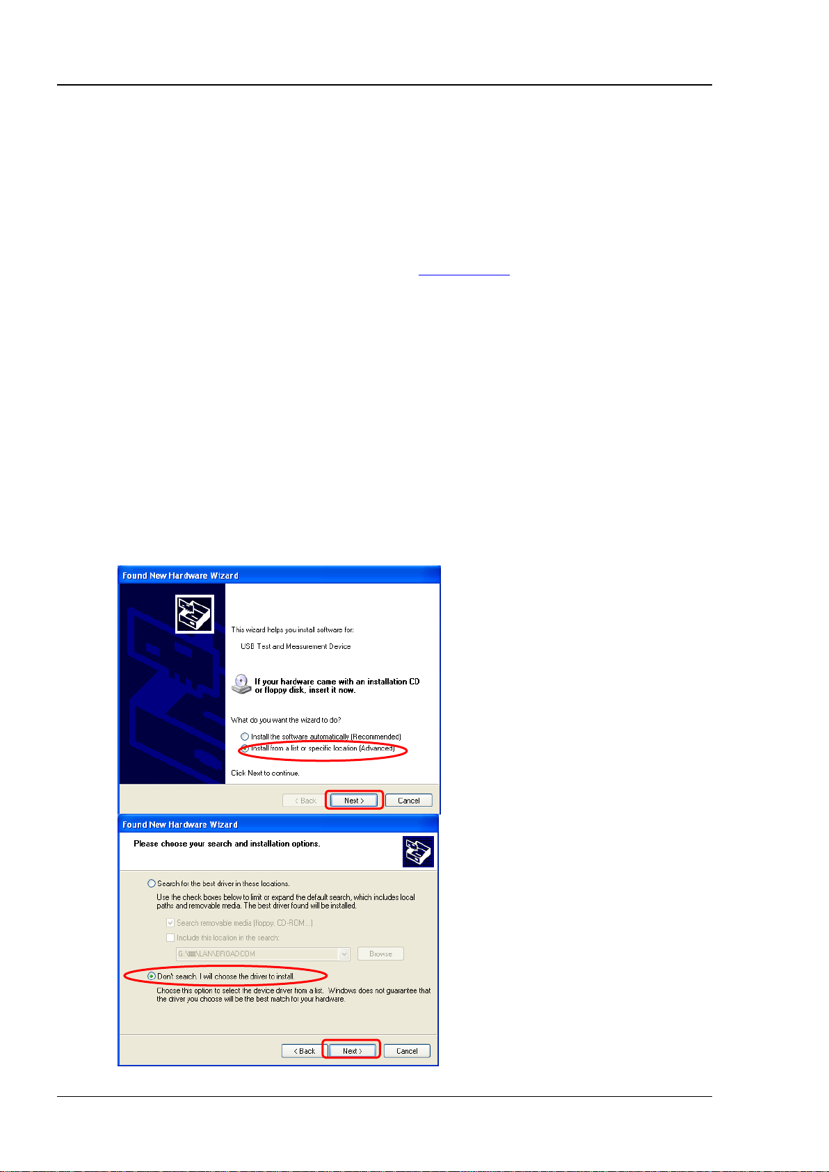
(2) Install the USB driver
This oscilloscope is a USBTMC device. Assuming that your PC has already been in stalled with
Ultra Sigma, after you connect the oscilloscope to the PC and turn both on for the first time (the
oscilloscope is automatically configured to the USB interface), the New Hardware Wizard as
shown in the figure below is displayed on the PC. Please install the “USB Test and Measurement
Device” driver following the directions in the wizard. The steps are as follows.
www.rigol.com or acquire it from the resource
1-2 DS1000Z Programming Guide
Page 11
Chapter 1 Programming Overview RIGOL
5
6
7
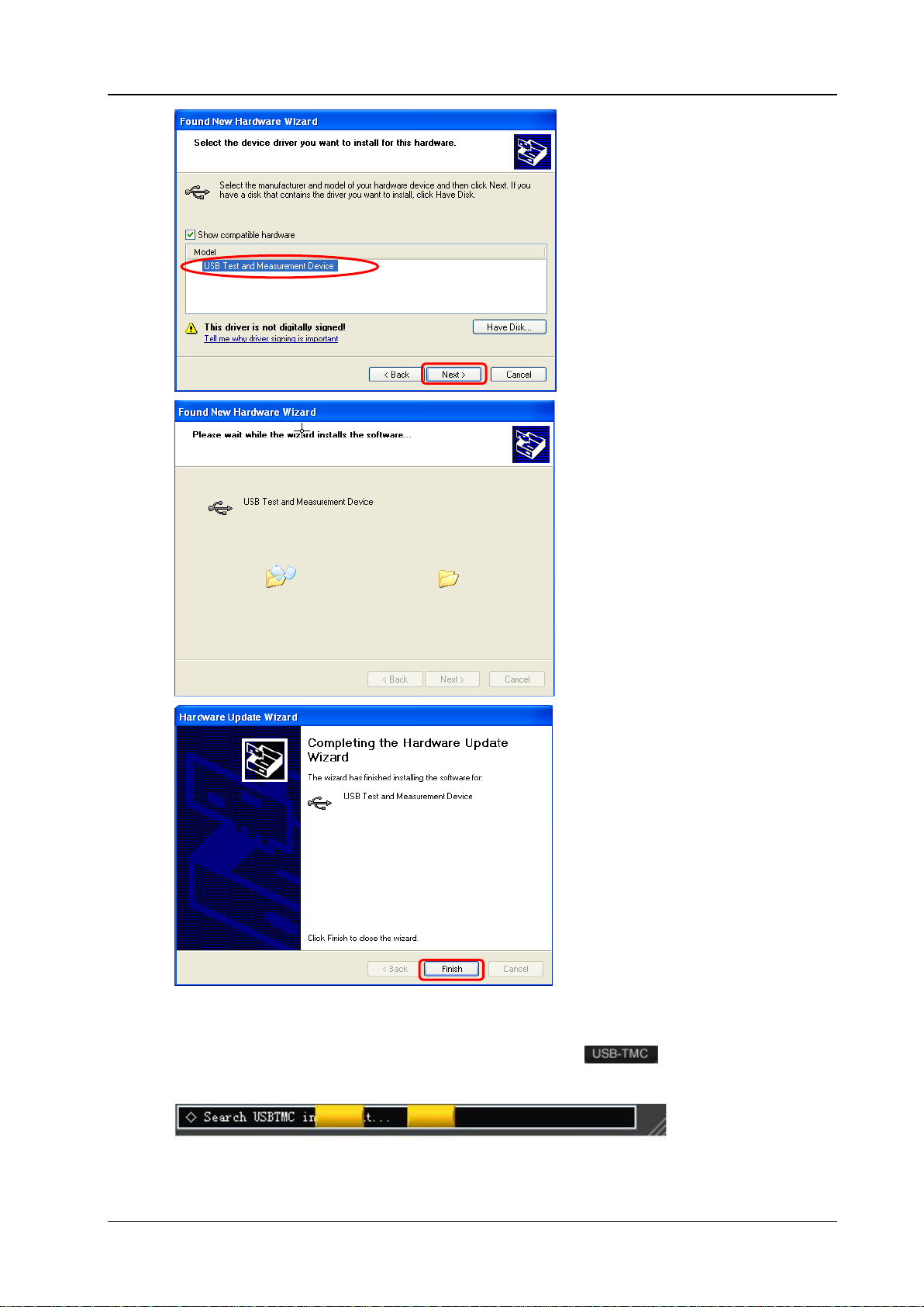
(3) Search for device resource
Start up the Ultra Sigma and the software will automatically search for the oscilloscope
resources currently connected to the PC. You can also click
resources. During the search, the status bar of the software is as shown in the figure below.
to search for the
DS1000Z Programming Guide 1-3
Page 12
RIGOL Chapter 1 Programming Overview
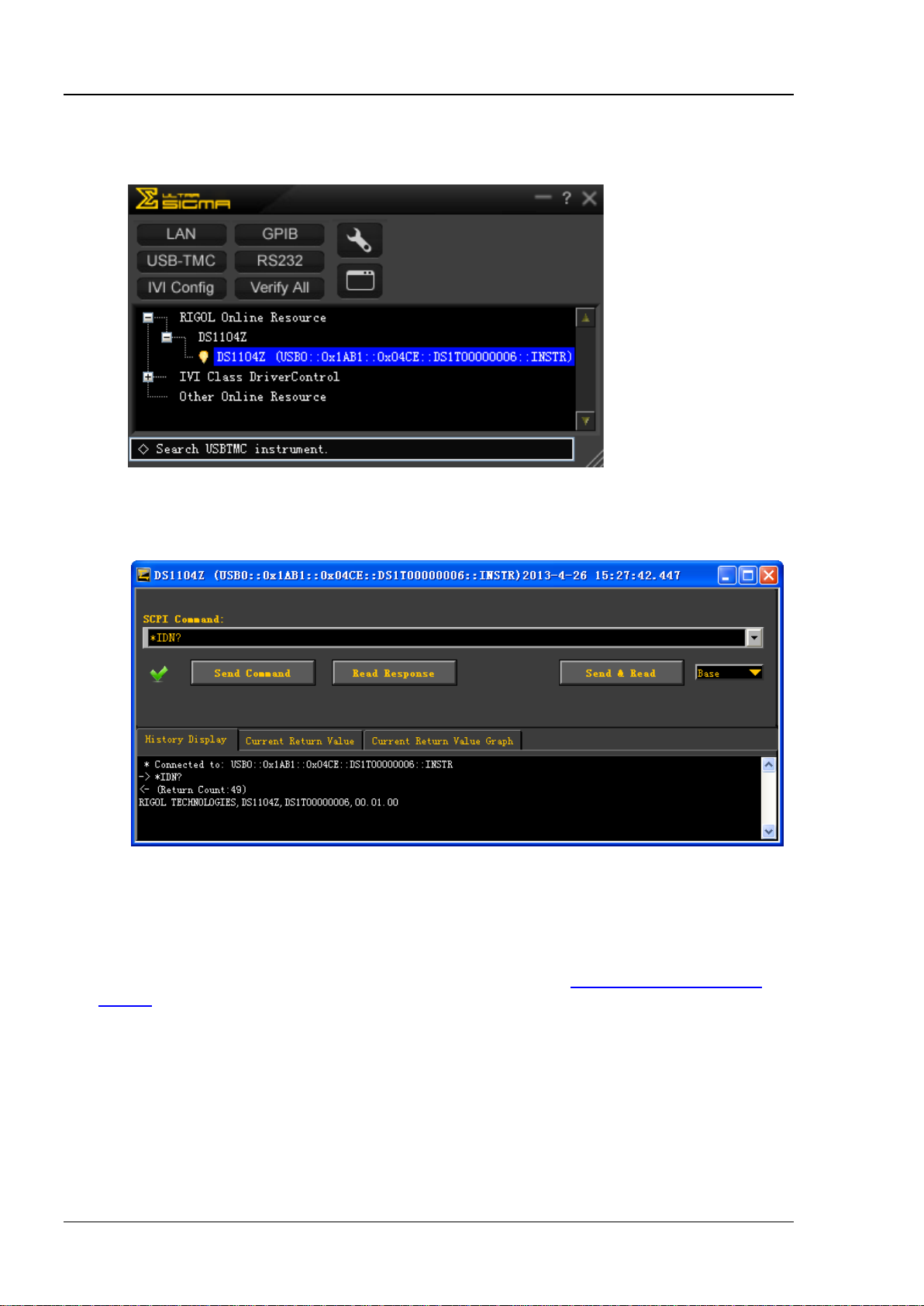
(4) View the device resources
The resources found will appear under the “RIGOL Online Resource” directory and the model
number and USB interface information of the instrument will also be displayed as shown in the
figure below.
(5) Communication test
Right click the resource name “DS1104Z (U S B0::0x1AB1::0x04CE::DS1T0000000006::INSTR)”
and select “SCPI Panel Control” to turn on the remote command control panel (as shown in the
figure below ) through which you can send commands and read data.
Remote Control Methods
1. User-defined Programming
Users can use the SCPI (Standard Commands for Programmable Instruments) commands to program
and control the oscilloscope. For details, refer to the introductions in Chapter 3
Demos.
2. Send SCPI Commands via the PC Software
You can control the oscilloscope remotely by sen ding SCPI commands via the PC software (Ultra Sigma)
provided by RIGOL
Automation Explorer” of NI (National Instruments Corporation) or the “Agilent IO Libraries Suite” of
Agilent (Agilent Technologies, Inc.).
. Besides, you can also control the inst rument using the “Measurement &
Programming
1-4 DS1000Z Programming Guide
Page 13

Chapter 1 Programming Overview RIGOL
SCPI Command Overview
SCPI (Standard Comm ands for Programmable Instruments) is a standardized instrument programming
language that is built upon the standard IEEE488.1 and IEEE 488.2 and conforms to various standards
(such as the floating point operation rule in IEEE754 standard, ISO646 7-bit coded character for
information intercha nge (equivalent to ASCll programming)). The SCPI commands provide a hierarchical
tree structure. Each command subsystem consists of a root keyword and on or more sub-keywords.
Syntax
The command string usually starts with ":"; the keywords are separated by ":" and are followed by the
parameter settings available; "?" is added at the end of the command string to indicate query; the
command and parameter are separated by space.
For example,
:ACQuire:TYPE <type>
:ACQuire:TYPE?
ACQuire is the root keyword of the command. TYPE is t he second-level keyword. The command string starts
with ":" which is also used t o separate the multiple-level keywords. <type> represents the parameters
available for setting. "?" represents query. The command :ACQuire:TYPE and parameter <type> are
separated by space.
"," is generally used for separating multiple parameters contained in the same command, for example,
:TRIGger:PATTern:PATTern <pattern1>,<pattern2>,<pattern3>,<pattern4>
Symbol Description
The following symbols will not be sent with the commands.
1. Braces {}
The parameters enclosed in the braces are optional and are usually separated by the vertical bar "|".
When using the command, one of the parameters must be selected.
2. Vertical Bar |
The vertical bar is used to separate multiple parameters and one of the parameters must be selected
when using the command.
3. Square Brackets []
The content in the square brackets can be omitted.
4. Triangle Brackets <>
The parameter enclosed in the triangle brackets must be replaced by an effective value.
DS1000Z Programming Guide 1-5
Page 14

RIGOL Chapter 1 Programming Overview
Parameter Type
1. Bool
The parameter could be OFF, ON, 0 or 1. For example,
:MEASure:ADISplay <bool >
:MEASure:ADISplay?
Wherein,
<bool> can be set to {{0|OFF}|{1|ON}}.
The query returns 0 or 1.
2. Discrete
The parameter could be any of the values listed. For example,
:ACQuire:TYPE <type>
:ACQuire:TYPE?
Wherein,
<type> can be set to NORMal|AVERages|PEAK|HRESolution.
The query returns the abbreviations (NORM, AVER, PEAK or HRES).
3. Integer
Unless otherwise noted, the parameter can be any integer (NR1 format) within the effective value
range. Note that do not set the parameter to a decimal, otherwise errors will occur. For example,
:DISPlay:GBRightne ss <br i ghtne ss >
:DISPlay:GBRightness?
Wherein,
<brightness> can be set to any integer between 0 and 100.
The query returns an integer between 0 and 100.
4. Real
The parameter can be any real number within the effective value range and this command accepts
decimal (NR2 format) and scientific notation (NR3 format) parameter input. For example,
:TRIGger:TIMeout:TIMe <NR3>
:TRIGger:TIMeout:TIMe?
Wherein,
<NR3> can be set to an y real number between 1.600000e-08 (namely 16ns) to 0.1e+02 (namely 10s).
The query returns a real number in scientific notation.
5. ASCII String
The parameter should be the combinations of ASCII characters.
For example,
:SYSTem:OPTion:INSTall <license>
Wherein,
<license> can be set to PDUY9N9QTS9PQSWPLAETRD3UJHYA.
Command Abbreviation
All the commands are case-insensitive and you can use any of them. If abbreviation is used, all the capital
letters in the command must be written completely. For example, the :MEASure:ADISplay? command can
be abbreviated to :MEAS:ADIS?.
1-6 DS1000Z Programming Guide
Page 15

Chapter 2 Command System RIGOL
Chapter 2 Command System
This chapter introduces the syntax, function, parameter and using instruct ion of each DS1000Z command.
Main topics of this chapter:
:AUToscale
:CLEar
:RUN
:STOP
:SINGle
:TFORce
:ACQuire Commands
:CALibrate Commands
:CHANnel<n> Commands
:CURSor Commands
:DISPlay Commands
IEEE488.2 Common Commands
:MATH Commands
:MASK Commands
:MEASure Commands
:REFerence Commands
[:SOURce[<n>]] Commands (DS1000Z-S Only)
:SYSTem Commands
:TIMebase Commands
:TRIGger Commands
:WAVeform Commands
Note:
1. Unless otherwise noted, this manual takes DS1104Z-S as an example to introduce the commands.
2. For parameter setting commands (for example, the time, frequency and amplitude), the osci lloscope
can only accept numbers and set the parameters using the default units; it cannot recognize the units
sent with the parameters. For the def ault unit of each parameter, please refer to the des cription in each
command in the following introductions.
DS1000Z Programming Guide 2-1
Page 16

RIGOL Chapter 2 Command System
Syntax
:AUToscale
at the front panel.
recorded waveform, this command is invalid.
Syntax
:CLEar
panel.
Command
:STOP
waveform, this command is invalid.
:AUToscale
Description Enable the waveform auto setting function. The oscilloscope will automatically adjust the
vertical scale, horizontal timebase and trigger mode according to the input signal to
realize optimum waveform display . This command is equivalent to pressing the AUTO key
Explanation Theoretically, wav eform auto setting function requires that the frequency of sine is no
lower than 41Hz; the duty cycle should be greater than 1% and the amplitude must
be at least 20mVpp for square.
When the pass/fail function is enabled (see the
this command, the oscilloscope will disable the pass/fail function firstly and then
execute the waveform auto setting function.
When the waveform record function is enabled or during the playback of the
:MASK:ENABle command), if you sent
:CLEar
Description Clear all the waveforms on the screen. If the oscilloscope is in the RUN state, waveform
will still be displayed. This command is equivalent to pressing the CLEAR key at the front
Related
:DISPlay:CLEar
:RUN
:STOP
Syntax :RUN
Description The :RUN command makes the oscilloscope start running and the :STOP command mak es
the oscilloscope stop running. These commands are equivalent to pressing the
RUN/STOP key at the front panel.
Explanation When the waveform record function is enabled or during the playback of the recorded
2-2 DS1000Z Programming Guide
Page 17

Chapter 2 Command System RIGOL
Syntax
:SINGle
the :TRIGger:SWEep SINGle command.
recorded waveform, this command is invalid.
:STOP
Syntax
:TFORce
the FORCE key at the front pa nel.
Command
:SINGle
Description Set the oscilloscope to the single trigger mode. This command is equivalent to the
following two operations: pressing the SINGLE key at the front panel and sending
Explanation In the single trigger mode, the oscilloscope triggers once when the trigger conditions
are met and then stops.
When the waveform record function is enabled or during the playback of the
Related
Commands
:TFORce
:RUN
:TFORce
Description Generate a trigger signal forcefully. This command is only applicable to the normal and
:TRIGger:SWEep command) and is equivalent to pressing
Related
single trigger modes (see the
:TRIGger:SWEep
DS1000Z Programming Guide 2-3
Page 18
RIGOL Chapter 2 Command System
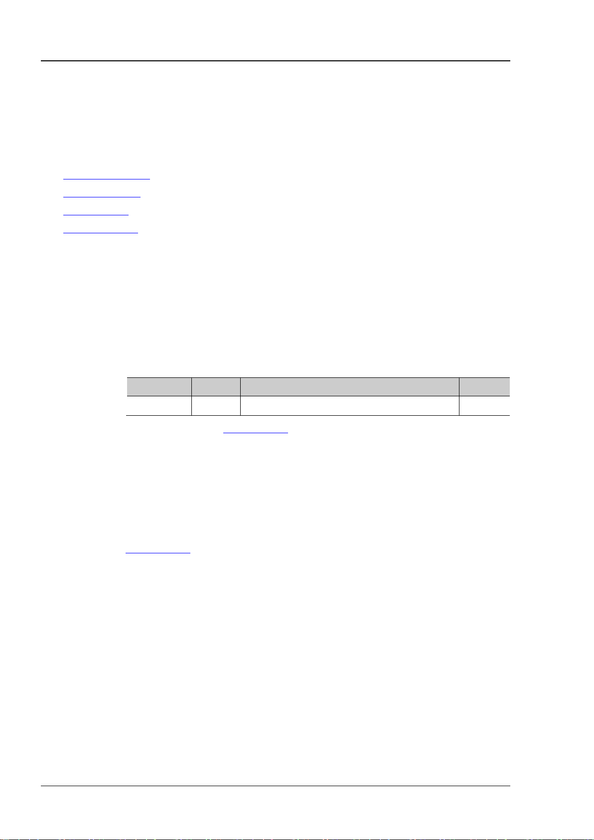
:ACQuire:AVERages?
Description
Set or query the number of averages under the average acquisition mode.
Name
Type
Range
Default
<count>
Integer
2n (n is an integer from 1 to 10)
2
response of the displayed waveform to the waveform changes will be.
Format
:ACQuire:AVERages? /*The query returns 128*/
:ACQuire Commands
The :ACQuire commands are used to set and query the memory depth, acquisition mode and the current
sample rate of the oscilloscope as well as to set the number of averages under the average acquisition
mode.
Command List
:ACQuire:AVERages
:ACQuire:MDEPth
:ACQuire:TYPE
:ACQuire:SRATe?
[1]
Note
: In the “Command List” in this m anual, the parameters in the setting commands and the query
commands are not included and you can refer to the complete introductions of the commands in the text
according to the keyword.
:ACQuire:AVERages
Syntax :ACQuire:AVERages <c ount>
[1]
:
Parameter
Explanation You can sent the :ACQuire:TYPE command to set the acquisition mode.
In the average acquisition mode, the greater the number of averages is, the lower
the noise will be and the higher the vertical resolution will be but the slower the
Return
Example
Related
Command
The query returns an integer between 2 and 1024.
:ACQuire:AVERages 12 8 /*Set the number of averages to 128*/
:ACQuire:TYPE
2-4 DS1000Z Programming Guide
Page 19

Chapter 2 Command System RIGOL
:ACQuire:MDEPth?
Name
Type
Range
Default
according to the current sample rate.
Format
:ACQuire:MDEPth? /*The query returns 12000*/
:TIMebase[:MAIN]:SCALe
:ACQuire:MDEPth
Syntax :ACQuire:MDEPth <mdep>
Description Set or query the memory depth of the oscilloscope namely the number of waveform
points that can be stored in a single trigger sample. The default unit is pts (points) .
Parameter
<mdep>
Discrete Refer to the Explanation
AUTO
Explanation When a single channel is on: {AUTO|12000|120000|1200000|12000000|24000000}
When dual channels are on: {AUTO|6000|60000|600000|6000000|12000000}
When four channels are on: {AUTO|3000|30000|300000|3000000|6000000}
Wherein, 24000000, 12000000 and 6000000 are options.
The relationship among the memory depth, sample rate and waveform length
satisfies the following equation:
Memory Depth = Sample Rate × Waveform Length
Wherein, the Waveform Length is the product of the horizontal timebase (set by
:TIMebase[:MAIN]:SCALe command) times the number of the horizontal scales
the
(12 for DS1000Z).
When AUTO is selected, the oscilloscope will select the memory depth automatically
Return
Example
Related
The query returns the actual number of points (integer) or AUTO.
:ACQuire:MDEPth 12000 /*Set the memory depth to 12000*/
:ACQuire:SRATe?
Commands
DS1000Z Programming Guide 2-5
Page 20

RIGOL Chapter 2 Command System
:ACQuire:TYPE?
Description
Set or query the acquisition mode when the oscilloscop e samples.
Name
Type
Range
Default
<type>
Discrete
{NORMal|AVERages|PEAK|HRESolution}
NORMal
average the neighboring points of the sample waveform to reduce the random noise
storage rate of the acquisition memory.
Format
Example
:ACQuire:TYPE AVERages /*Select the average acquisition mode*/
Command
:ACQuire:TYPE
Syntax :ACQuire:TYPE <type>
Parameter
Explanation
Return
NORMal
: in this mode, the oscilloscope samples the signal at equa l time interval to
rebuild the waveform. For most of the waveforms, the best display effect can be
obtained using this mode.
AVERages: in
this mode, the oscilloscope averages the waveforms from multiple
samples to reduce the random noise of the input signal and improve the vertical
resolution. The number of av er ages can be s et by th e
:ACQuire:AVERages command.
The greater the number of av erag es is, the lo wer the noise will be an d the higher the
vertical resolution will be but the slower the response of the displayed waveform to
the waveform changes will be.
PEAK (Peak Detect): in this mode, the oscilloscope acquires the maximum and
minimum values of the signal within the sample interval to get the envelope of the
signal or the narrow pulse of the signal that might be lost. In this mode, signal
confusion can be prevented but the noise displayed would be larger.
HRESolution (High Resolution): this mode uses a kind of ultra-sample technique to
on the input signal and generate much smoother waveforms on the screen. This is
generally used when the sample rate of the digital converter is higher than the
The query returns NORM, AVER, PEAK or HRES.
Related
:ACQuire:AVERages
2-6 DS1000Z Programming Guide
Page 21

Chapter 2 Command System RIGOL
:ACQuire:SRATe?
Description
Query the current sample rate. The default unit is Sa/s.
Format
Example
:ACQuire:SRATe? /*The query returns 2.000000e+09*/
:ACQuire:SRATe?
Syntax
Explanation Sample rate is the sample frequency of the oscilloscope, namely the wav eform points
sampled per second.
The relationship among the memory depth, sample rate and waveform length
satisfies the following equation:
Memory Depth = Sample Rate × Waveform Length
Wherein, the Memory Depth can be set us ing the
the Waveform Length is the product of the horizontal timebase (set by
:TIMebase[:MAIN]:SCALe command) times the number of the horizontal scales
the
(12 for DS1000Z).
:ACQuire:MDEPth command, and
Return
Related
Commands
The query returns the sample rate in scientifi c notation.
:ACQuire:MDEPth
:TIMebase[:MAIN]:SCALe
DS1000Z Programming Guide 2-7
Page 22

RIGOL Chapter 2 Command System
Syntax
:CALibrate:QUIT
Description
Exit the calibration at any time.
Command
Syntax
:CALibrate:STARt
send the :CALibrate:QUIT command to quit the self-calibration.
Command
:CALibrate Commands
Command List:
:CALibrate:QUIT
:CALibrate:STARt
:CALibrate:QUIT
Related
:CALibrate:STARt
:CALibrate:STARt
Description The oscilloscope starts to execute the self-calibration.
Explanation The self-calibration can make the oscilloscope quickly re ach its optimum working
state to obtain the most accurate measurement values.
During the self-calibration, all the channels of the oscilloscope must be disconnected
from the inputs.
The functions of most of the keys are disabled during the self-calibration. You can
Related
:CALibrate:QUIT
2-8 DS1000Z Programming Guide
Page 23
Chapter 2 Command System RIGOL
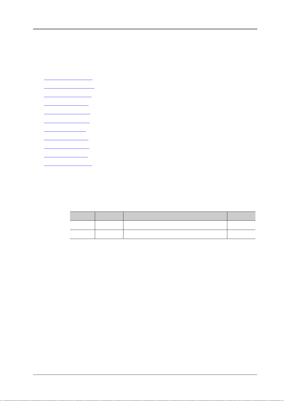
:CHANnel<n>:BWLimit?
Description
Set or query the bandwidth limit p arameter of the specified channel .
Name
Type
Range
Default
<n>
Discrete
{1|2|3|4}
--
Discrete
OFF
frequency components.
Format
Example
:CHANnel1:BWLimit 20M /*Enable the 20MHz bandwidth limit*/
:CHANnel<n> Commands
The :CHANnel<n> commands are used to set or query the vertical system parameters, such as the
bandwidth limit, coupling, vertical scale and vertical offset.
Command List:
:CHANnel<n>:BWLimit
:CHANnel<n>:COUPling
:CHANnel<n>:DISPlay
:CHANnel<n>:INVert
:CHANnel<n>:OFFSet
:CHANnel<n>:RANGe
:CHANnel<n>:TCAL
:CHANnel<n>:SCALe
:CHANnel<n>:PROBe
:CHANnel<n>:UNITs
:CHANnel<n>:VERNier
:CHANnel<n>:BWLimit
Syntax :CHANnel<n>:BWLimit <type>
Parameter
<type>
{20M|OFF}
Explanation OFF: disable the bandwidth limit and the hi gh frequency components of the signal
under test can pass the channel.
20M: enable the bandwidth limit and the high frequency components that exceed 20
MHz are attenuated.
Enabling the bandwidth limit can reduce the no ise, but can also attenuate the high
Return
The query returns 20M or OFF.
DS1000Z Programming Guide 2-9
Page 24
RIGOL Chapter 2 Command System
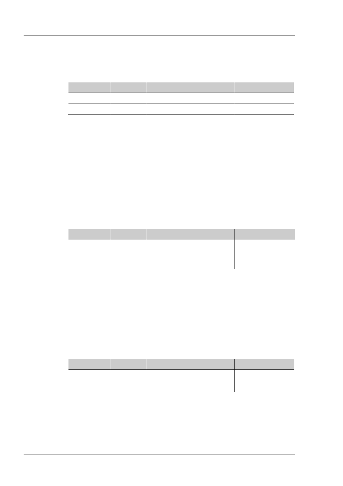
:CHANnel<n>:COUPling?
Description
Set or query the coupling mode of the specified channel.
Name
Type
Range
Default
<n>
Discrete
{1|2|3|4}
--
<coupling>
Discrete
{AC|DC|GND}
DC
GND: the DC and AC components of the signal under test a re both blocked.
Format
Example
:CHANnel1:COUPling AC /*Select the AC coupling mode*/
:CHANnel<n>:DISPlay?
Description
Enable or disable the specified channel or query the status of the specified channel.
Name
Type
Range
Default
<n>
Discrete
{1|2|3|4}
--
Others: 0|OFF
Format
Example
:CHANnel1:DISPlay ON /*Enable CH1*/
:CHANnel<n>:INVert?
the inverted display mode of the specified channel.
Name
Type
Range
Default
inverted taking the vertical offset horizontal line as reference.
Format
:CHANnel<n>:COUPling
Syntax :CHANnel<n>:COUPling <coupling>
Parameter
Explanation AC: the DC components of the signal under test are blocked.
DC: t he DC and AC components of the signal under test can both pass the channel.
Return
The query returns AC, DC or GND.
:CHANnel<n>:DISPlay
Syntax :CHANnel<n>:DISPlay <bool>
Parameter
<bool> Bool {{0|OFF}|{1|ON}}
Return
The query returns 0 or 1.
:CHANnel<n>:INVert
CH1: 1|ON
Syntax :CHANnel<n>:INVer t <bool>
Description Enable or disable the inverted display mode of the specified channel or query the status of
Parameter
<n> Discrete {1|2|3|4} -<bool> Bool {{0|OFF}|{1|ON}} 0|OFF
Explanation When the inverted display mode is enabled, the oscilloscope displays the waveform
Return
The query returns 0 or 1.
Example :CHANnel1:INVert ON /*Enable the inverted display mode of CH1*/
2-10 DS1000Z Programming Guide
Page 25
Chapter 2 Command System RIGOL
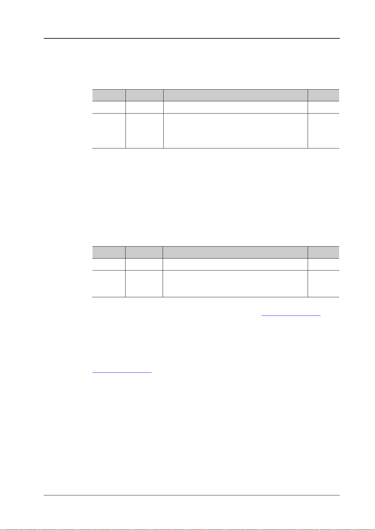
:CHANnel<n>:OFFSet?
Description
Set or query the vertical offset of the specified channel. The default unit is V.
Name
Type
Range
Default
<n>
Discrete
{1|2|3|4}
--
vertical scale<500mV/div: -2V to +2V
Format
:CHANnel1:OFFSet? /*The query returns 1.000000e-02*/
:CHANnel<n>:RANGe?
Description
Set or query the vertical range of the specified channel. The default unit is V.
Name
Type
Range
Default
8mV to 80V
command.
Format
:CHANnel1:RANGe? /*The query returns 8.000000e+00*/
Command
:CHANnel<n>:OFFSet
Syntax :CHANnel<n>:OFFSet <offset>
Parameter
Related to the current vertical scale and probe
<offset> Real
ratio. When the probe ratio is 1,
vertical scale≥500mV/div: -100V to +100V
0V
Return
Example
The query returns the vertical offset in scientific notation.
:CHANnel1:OFFSet 0.01 /*Set the vertical offset of CH1 to 10mV*/
:CHANnel<n>:RANGe
Syntax :CHANnel<n>:RANGe <range>
Parameter
<n> Discrete {1|2|3|4} --
Related to the current vertical scale and probe
<range> Real
ratio. When the probe ratio is 1,
Explanation This command indirectly modifie s the vertical scale of the specified channel (vertical
:CHANnel<n>:SCALe
Return
range=8*vertical scale). The vertical scale can be set by the
The query returns the vertical range in scientific notation.
8V
Example
Related
:CHANnel1:RANGe 8 /*Set the vertical range of CH1 to 8V*/
:CHANnel<n>:SCALe
DS1000Z Programming Guide 2-11
Page 26
RIGOL Chapter 2 Command System
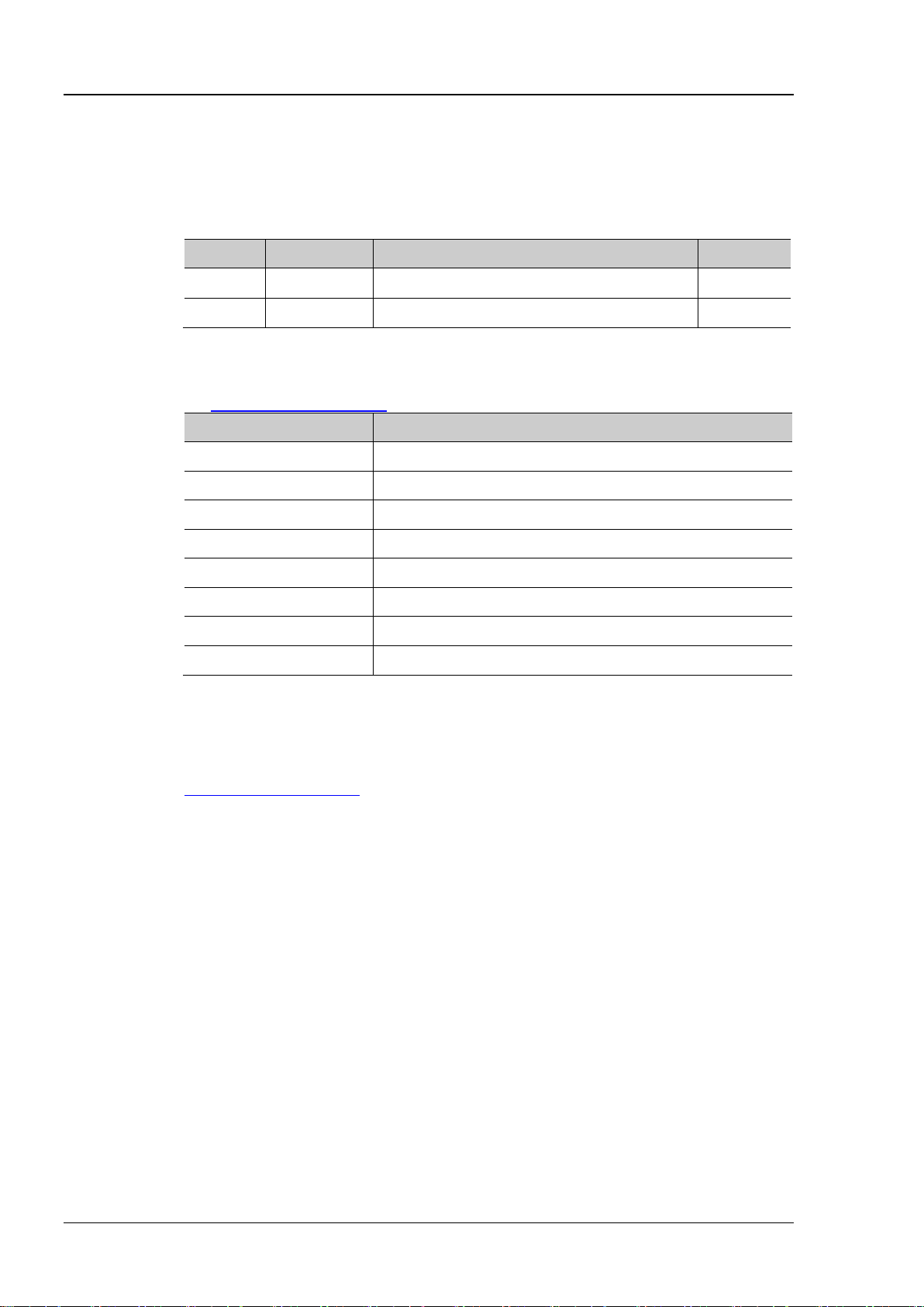
:CHANnel<n>:TCAL?
Name
Type
Range
Default
<n>
Discrete
{1|2|3|4}
--
Horizontal Timebase
Step of the Delay Calibration Time
5ns
100ps
20ns
400ps
50ns
1ns
100ns
2ns
500ns
10ns
1μs and above
20ns
Format
:CHANnel1:TCAL? /*The query returns2.000000e-05*/
Command
:CHANnel<n>:TCAL
Syntax :CHANnel<n>:TCAL <val>
Description Set or query the delay calibration time of the specified channel to calibrate the zero offset
of the corresponding channel. The default unit is s.
Parameter
<val> Real -100ns to 100ns 0.00ns
Explanation <val> can only be set to the specific values in the specified step. If the parameter you
sent is not one of the specif ic values, the parameter will be set to the nearest specific
values automatically. The step varies with the horizontal timebase (set by
:TIMebase[:MAIN]:SCALe command).
the
10ns 200ps
Return
Example
Related
200ns 4ns
The query returns the delay calibration time in scientific notation.
:CHANnel1:TCAL 0.00002 /*Set the delay calibration time to 20ns*/
:TIMebase[:MAIN]:SCALe
2-12 DS1000Z Programming Guide
Page 27
Chapter 2 Command System RIGOL
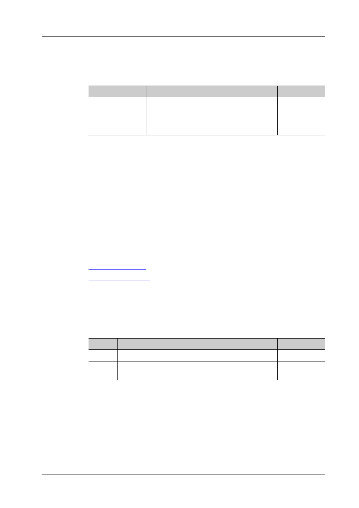
:CHANnel<n>:SCALe?
Description
Set or query the vertical scale of the specified channel. The default unit is V.
Name
Type
Range
Default
probe ratio = 10 (default): 10mV to 100V
be used to improve the display amplitude of the waveform to view the signal details.
Format
:CHANnel1:SCALe? /*The query retur ns 1.000000e+00*/
:CHANnel<n>:VERNier
:CHANnel<n>:PROBe?
Description
Set or query the probe ratio of the specified channel.
Name
Type
Range
Default
00|200|500|1000}
Setting the probe ratio will affect the range of the vertical scale.
Format
:CHANnel1:PROBe? /*The query returns 1.000000e+01*/
Command
:CHANnel<n>:SCALe
Syntax :CHANnel<n>:SCALe <scale>
Parameter
<n> Discrete {1|2|3|4} -<scale> Real Related to the current probe ratio.
probe ratio = 1: 1mV to 10V
1V (the probe
ratio is 10)
Explanation The range of the vertical scale is related to the current probr ratio (set by
:CHANnel<n>:PROBe command). As the default probe ratio of DS1000Z is 10,
the
the default value of <scale> is the value when the probe ratio is 10.
You can use the
:CHANnel<n>:VERNier command to enable or disable the fine
adjustment of the vertical scale. By default, the fine adjustment is off. At this point,
you can only set the vertical scale in 1-2-5 step, namely 1mV, 2mV, 5mV, 10mV, …,
10V. When the fine adjustment is on, you can further adjust the vertical scale within
a relatively smaller range to improve the vertical resolution. If the am plitude of the
input waveform is a little bit greater than the full scale under the cur rent scale and
the amplitude would be a little bit lower if the next scale is used, fine adjustment can
Return
Example
Related
The query returns the vertical scale in scientific notation.
:CHANnel1:SCALe 1 /*Set the vertical scale of CH1 to 1V*/
:CHANnel<n>:PROBe
Command
:CHANnel<n>:PROBe
Syntax :CHANnel<n>:PROBe <atten>
Parameter
<n> Discrete {1|2|3|4} -<atten> Discrete {0.01|0.02|0.05|0.1|0.2|0.5|1|2|5|10|20|50|1
10
Explanation Setting the probe ratio refers to multiply the signal sampled with the specified ratio
and then display the result (the actual amplitude of the signal will be not affected).
Return
Example
Related
DS1000Z Programming Guide 2-13
The query returns the probe ratio in scientific notation.
:CHANnel1:PROBe 10 /*Set the probe ratio to 10*/
:CHANnel<n>:SCALe
Page 28

RIGOL Chapter 2 Command System
:CHANnel<n>:UNITs?
Description
Set or query the amplitude display unit of the specified channel.
Name
Type
Range
Default
<n>
Discrete
{1|2|3|4}
--
Format
Example
:CHANnel1:UNITs VOLTage /*Set the amplitude display unit of CH1 to V*/
:CHANnel<n>:VERNier?
query the fine adjustment status of the vertical scale of the specified channel.
Name
Type
Range
Default
<n>
Discrete
{1|2|3|4}
--
view the signal details.
Format
Example
:CHANnel1:VERNier ON /*Enable the fine adjustment of the vertical scale of CH1*/
Command
:CHANnel<n>:UNITs
Syntax :CHANnel< n >: UNITs <units>
Parameter
<units> Discrete {VOLTage|WATT|AMPere|UNKNown} VOLTage
Return
The query returns VOLT, WATT, AMP or UNKN.
:CHANnel<n>:VERNier
Syntax :CHANnel<n>:VERNier <bool>
Description Enable or disable the fine adjustment of the vertical scale of the specified channel, or
Parameter
<bool> Bool {{0|OFF}|{1|ON}} 0|OFF
Explanation By default, the fine adjustment is off. At this point, you can only set the vertical scale in
1-2-5 step, namely 1 mV, 2mV, 5mV, 10mV…10V. When the fine adjustment is on, you can
further adjust the vertical scale within a relatively smaller range to improve the vertical
resolution. If the amplitude of the input waveform is a little bit greater than the full scale
under the current scale and the amplitude would be a little bit lower if the next scale is
used, fine adjustment can be used to improve the display amplitude of the waveform to
Return
Related
The query returns 0 or 1.
:CHANnel<n>:SCALe
2-14 DS1000Z Programming Guide
Page 29

Chapter 2 Command System RIGOL
Description
Set or query the cursor measurement mode.
Name
Type
Range
Default
<mode>
Discrete
{OFF|MANual|TRACk|AUTO|XY}
OFF
horizontal timebase mode is XY.
Format
:CURSor Commands
The :CURSor commands are used to measure the X-axis value (such as time) and Y-axis value (such as
voltage) of the waveform displayed on the screen.
Command List:
:CURSor:MODE
:CURSor:MANual
:CURSor:TRACk
:CURSor:AUTO:ITEM
:CURSor:XY
:CURSor:MODE
Syntax :CURSor:MODE <mode>
:CURSor:MODE?
Parameter
Explanation OFF: disable the cur sor measurement function.
MANual: enable the manual cursor measurement mode.
TRACk: enable the track cursor measurement mode.
AUTO: enable the auto cursor measurement mode.
XY: enable the XY cursor measurement mode. This mode is valid only when the
Return
The query returns OFF, MAN, TRAC, AUTO or XY.
Example :CURSor:MODE MANual /*Enable the manual cursor measurement mode*/
Related
Commands
:CURSor:MANual
:CURSor:TRACk
:CURSor:XY
:TIMebase:MODE
DS1000Z Programming Guide 2-15
Page 30
RIGOL Chapter 2 Command System
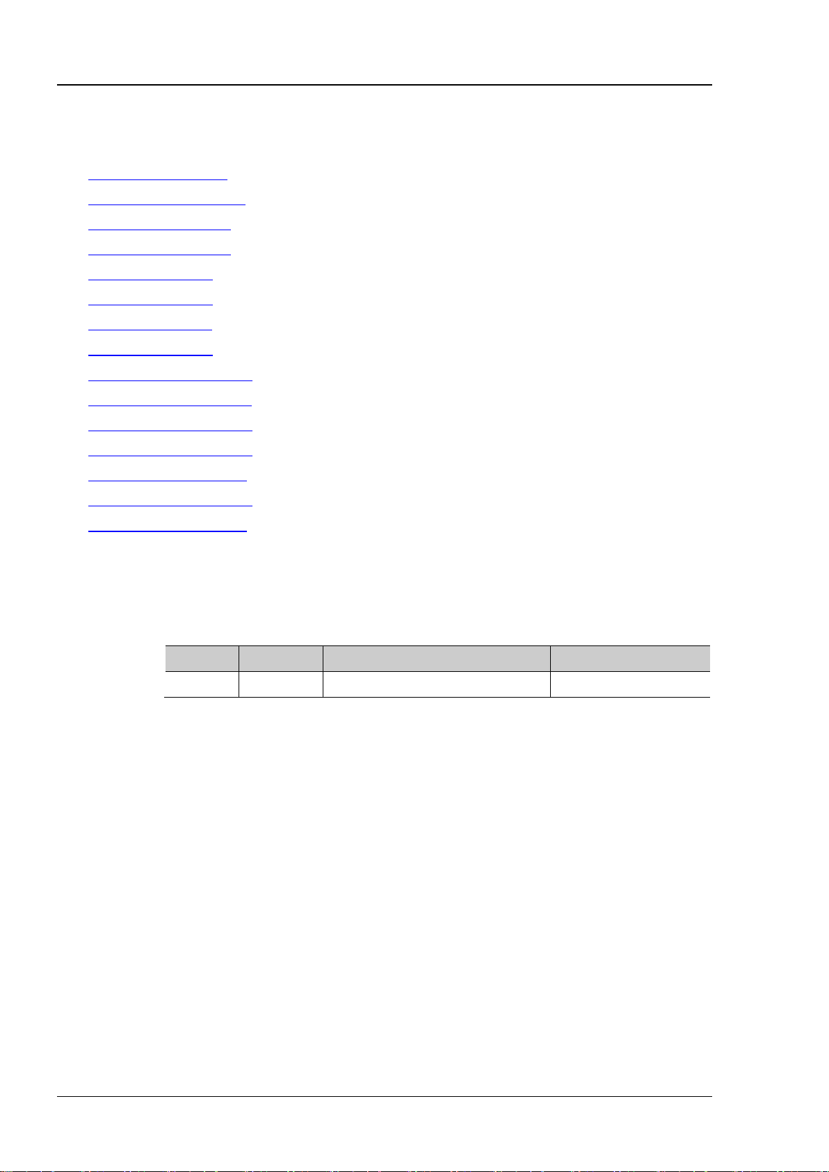
:CURSor:MANual:TYPE?
Description
Set or query the cursor type in manual cursor measurement mode.
Name
Type
Range
Default
<type>
Discrete
{X|Y}
X
parameters.
Format
:CURSor:MANual
Command List:
:CURSor:MANual:TYPE
:CURSor:MANual:SOURce
:CURSor:MANual:TUNit
:CURSor:MANual:VUNit
:CURSor:MANual:AX
:CURSor:MANual:BX
:CURSor:MANual:AY
:CURSor:MANual:BY
:CURSor:MANual:AXValue?
:CURSor:MANual:AYValue?
:CURSor:MANual:BXValue?
:CURSor:MANual:BYValue?
:CURSor:MANual:XDELta?
:CURSor:MANual:IXDELta?
:CURSor:MANual:YDELta?
:CURSor:MANual:TYPE
Syntax :CURSor:MANual:TYPE <t y pe >
Parameter
Explanation X: select the X type cursors. The X type cursors are a vertical solid line (cursor A) and
a vertical dotted line (cursor B) and are usually used to measure the time
parameters.
Y: select the Y type cursors. The Y type cursors are a horizontal solid line (cursor A)
and a horizontal dotted line (cursor B) and are usually used to measure the voltage
Return
Example :CURSor:MANual:TYPE Y /*select the Y type cursors*/
The query returns X or Y.
2-16 DS1000Z Programming Guide
Page 31

Chapter 2 Command System RIGOL
:CURSor:MANual:SOURce?
Description
Set or query the channel source of the manual cursor measurement mode.
Name
Type
Range
Default
CHANnel3|CHANnel4|MATH}
Explanation
Only the channel that is enabled currently can be selected.
Format
measurement mode to CH2*/
:CURSor:MANual:TUNit?
Description
Set or query the h orizontal unit in the manual cursor measurement mode.
Name
Type
Range
Default
<unit>
Discrete
{S|HZ|DEGRee|PERCent}
S
PERCent: AX, BX and BX-AX are in “%”.
Format
Example
:CURSor:MANual:TUNit DEGRee /*Set the horizontal unit to “degree”*/
:CURSor:MANual:VUNit?
Description
Set or query the vertical unit in the manual curs or measurement mode.
Name
Type
Range
Default
<unit>
Discrete
{PERCent|SOURce}
SOURce
automatically set to the unit of the current source.
Format
Example
:CURSor:MANual:VUNit PERCent /*Set the vertical unit to %*/
Command
:CURSor:MANual:SOURce
Syntax :CURSor:M A Nua l :SO UR ce <so urce>
Parameter
Return
Example
<source> Discrete {CHANnel1|CHANnel2|
The query returns CHAN1, CHAN2, CHAN3, CHAN4 or MATH.
:CURSor:MANual:SOURce CHANnel2 /*Set the channel source of the manual cursor
CHANnel1
:CURSor:MANual:TUNit
Syntax :CURSor:MANual:TUNit <unit>
Parameter
Explanation S: AX, BX and BX-AX in the measurement results are in “s” and 1/|dX| is in “Hz”.
HZ: AX, BX and BX-AX in the measurement results are in “Hz” and 1/|dX| is in “s”.
DEGRee: AX, BX and BX-AX are in “degree”.
Return
The query returns S, HZ, DEGR or PERC.
:CURSor:MANual:VUNit
Syntax :CURSor:MANual:VUNit <unit>
Parameter
Explanation PERCent: AY, BY and BY-AY in the measurement results are in “%”.
SOURce: the units of AY, BY and BY-AY in the measurement results will be
Return
Related
The query returns PERC or SOUR.
:CHANnel<n>:UNITs
DS1000Z Programming Guide 2-17
Page 32

RIGOL Chapter 2 Command System
:CURSor:MANual:AX?
Description
Set or query the horizontal position of cursor A in the manual cursor measurement mode.
Name
Type
Range
Default
pixel range is from 0 to 400.
Format
Example
:CURSor:MANual:AX 200 /*Set the horizontal position of cursor A to 200*/
:CURSor:MANual:BX?
Description
Set or query the horizontal position of cursor B in the manual cursor measurement mode.
Name
Type
Range
Default
<x>
Integer
5 to 594
500
pixel range is from 0 to 400.
Format
Example
:CURSor:MANual:BX 200 /*Set the horizontal position of cursor B to 200*/
:CURSor:MANual:AY?
Description
Set or query the vertical position of cursor A in the manual curs or measurement mode.
Name
Type
Range
Default
<y>
Integer
5 to 394
100
pixel range is from 0 to 400.
Format
:CURSor:MANual:AX
Syntax :CURSor:MA Nua l :AX < x>
Parameter
<x> Integer 5 to 594 100
Explanation The horizontal and vertical positions of the cursor a re defined by the pixel coordinate of
the screen. The pixel coordinate of the screen ranges from (0,0) to (600,400). Wherein,
(0,0) is located at the left top corner of the screen and (600,400) is located at the right
bottom corner of the screen. The horizontal pixel range is from 0 to 600 and t he vertical
Return
The query returns an integer between 5 and 594.
:CURSor:MANual:BX
Syntax :CURSor:MANual:BX <x>
Parameter
Explanation The horizontal and vertical positions of the cursor are defined by the pixel coordinate of
the screen. The pixel coordinate of the screen ranges from (0,0) to (600,400). Wherein,
(0,0) is located at the left top corner of the screen and (600,400) is located at the right
bottom corner of the screen. The horizontal pixel range is from 0 to 600 and the vertical
Return
The query returns an integer between 5 and 594.
:CURSor:MANual:AY
Syntax :CURSor:MANual:AY <y>
Parameter
Explanation The horizontal and vertical positions of the cursor are defined by the pixel coordinate of
the screen. The pixel coordinate of the screen ranges from (0,0) to (600,400). Wherein,
(0,0) is located at the left top corner of the screen and (600,400) is located at the right
bottom corner of the screen. The horizontal pixel range is from 0 to 600 and the vertical
Return
The query returns an integer between 5 and 394.
Example :CURSor:MANual:AY 200 /*Set the vertical position of cursor A to 200*/
2-18 DS1000Z Programming Guide
Page 33

Chapter 2 Command System RIGOL
:CURSor:MANual:BY?
Description
Set or query the vertical position of cursor B in the manual cursor measurement mode.
Name
Type
Range
Default
pixel range is from 0 to 400.
Format
Example
:CURSor:MANual:BY 200 /*Set the vertical position of cursor B to 200*/
Syntax
:CURSor:MANual:AXValue?
on the horizontal unit currently selected.
Format
Example
:CURSor:MANual:AXValue? /*The query returns -3.000000e-06*/
:CURSor:MANual:TUNit
Syntax
:CURSor:MANual:AYValue?
on the vertical unit currently selected.
Format
Example
:CURSor:MANual:AYValue? /*The query returns -4.000000e-06*/
:CURSor:MANual:VUNit
Syntax
:CURSor:MANual:BXValue?
on the horizontal unit currently selected.
Format
Example
:CURSor:MANual:BXValue? /*The query returns -3.000000e-06*/
:CURSor:MANual:TUNit
:CURSor:MANual:BY
Syntax :CURSor:MANual:BY <y>
Parameter
<y> Integer 5 to 394 300
Explanation The horizontal and vertical positions of the cursor are defined by the pixel coordinate of
the screen. The pixel coordinate of the screen ranges from (0,0) to (600,400). Wherein,
(0,0) is located at the left top corner of the screen and (600,400) is located at the right
bottom corner of the screen. The horizontal pixel range is from 0 to 600 and the vertical
Return
The query returns an integer between 5 and 394.
:CURSor:MANual:AXValue?
Description Query the X value of cursor A in the manual cursor measurement mode. The unit depends
Return
Related
The query returns the X value of cursor A in scientific notation.
:CURSor:MANual:AX
Commands
:CURSor:MANual:AYValue?
Description Query the Y value of cursor A in the manual cursor measurement mode. The unit depends
Return
The query returns the Y value of cursor A in scientific notation.
Related
:CURSor:MANual:AY
Commands
:CURSor:MANual:BXValue?
Description Query the X value of cursor B in the manual cursor measurement mode. T he unit depends
Return
Related
Commands
DS1000Z Programming Guide 2-19
The query returns the X value of cursor B in scientific notation.
:CURSor:MANual:BX
Page 34

RIGOL Chapter 2 Command System
Syntax
:CURSor:MANual:BYValue?
on the vertical unit currently selected.
Format
Example
:CURSor:MANual:BYValue? /*The query returns-4.000000e-06*/
:CURSor:MANual:VUNit
Syntax
:CURSor:MANual:XDELta?
cursor measurement mode. The unit depends o n the horizontal unit currently selected.
Format
Example
:CURSor:MANual:XDELta? /*The query returns 6.120000e-06*/
:CURSor:MANual:TUNit
Syntax
:CURSor:MANual:IXDELta?
the horizontal unit currently selected.
Format
Example
:CURSor:MANual:IXDELta? /*The query returns 1.120000e+05*/
:CURSor:MANual:TUNit
Syntax
:CURSor:MANual:YDELta?
cursor measurement mode. The unit depends o n the vertical unit currently selected.
Format
Example
:CURSor:MANual:YDELta? /*The quer y returns -4.700000e+00*/
:CURSor:MANual:VUNit
:CURSor:MANual:BYValue?
Description Query the Y value of cursor B in the manual cursor measurement mode. The unit depend s
Return
Related
Commands
The query returns the Y value of cursor B in scient ific notation.
:CURSor:MANual:BY
:CURSor:MANual:XDELta?
Description Query the difference between the X v alues of cursor A an d cursor B (BX-AX) in the manual
Return
Related
Commands
The query returns the difference in scientific notation.
:CURSor:MANual:AX
:CURSor:MANual:BX
:CURSor:MANual:IXDELta?
Description Query the reciprocal of the absolute v alue of the diff erence between the X values of cursor
A and cursor B (1/|dX|) in the manual cursor measurement mode. The unit depends on
Return
Related
Commands
The query returns 1/|dX| in scientific notation.
:CURSor:MANual:AX
:CURSor:MANual:BX
:CURSor:MANual:YDELta?
Description Query the difference between the Y values of cursor A and cursor B (BY-AY) in the manual
Return
Related
Commands
The query returns the difference in scientific notation.
:CURSor:MANual:AY
:CURSor:MANual:BY
2-20 DS1000Z Programming Guide
Page 35
Chapter 2 Command System RIGOL
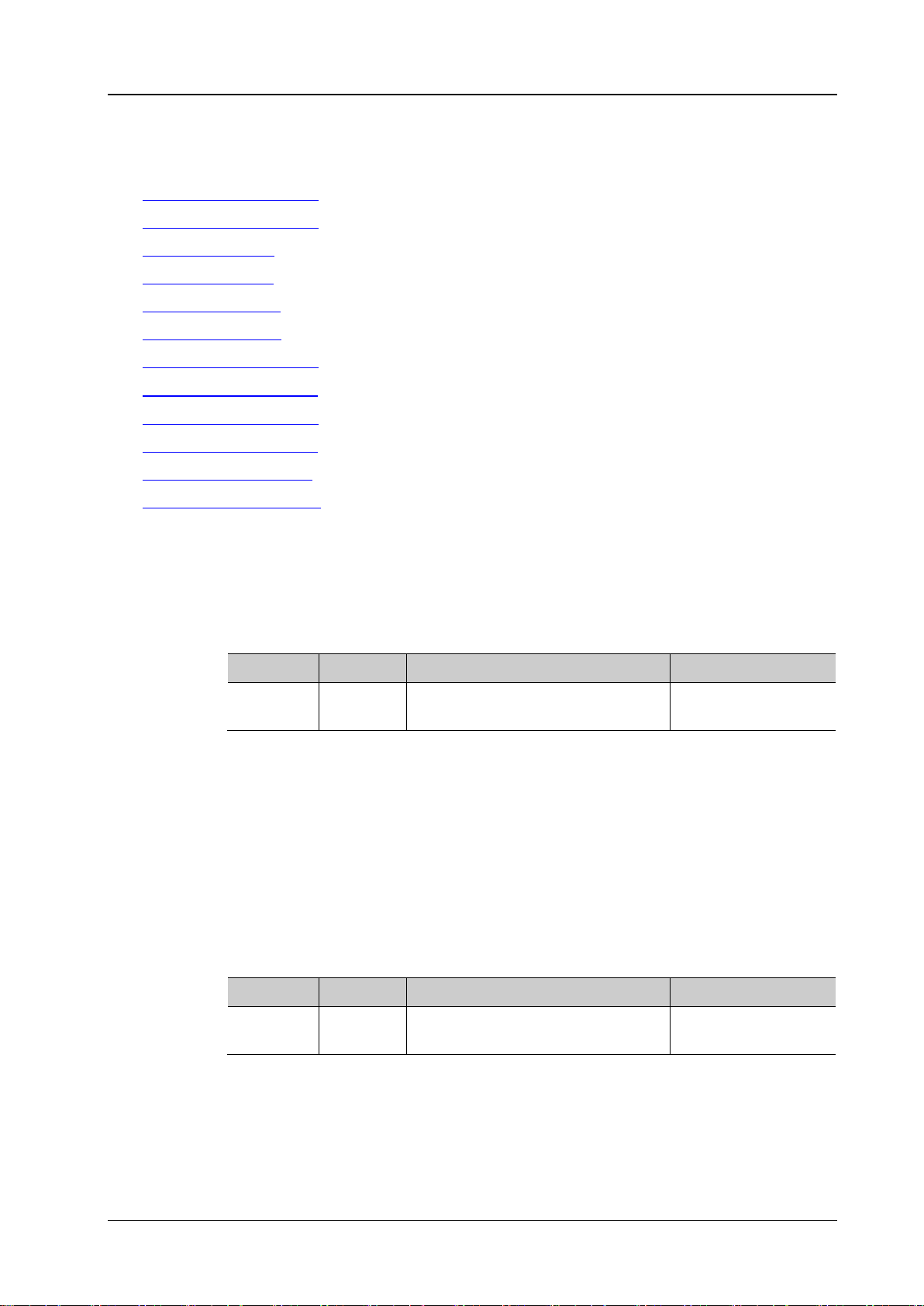
:CURSor:TRACk:SOURce1?
Description
Set or query the channel source of cursor A in the track cursor measurement mode.
Name
Type
Range
Default
CHANnel3|CHANnel4|MATH}
Explanation
Only the channels enabled can be selected as the channel source.
Format
Example
:CURSor:TRACk: SO UR ce 1 CH ANne l 2 /*Set the channel source to CH2*/
:CURSor:TRACk:SOURce2?
Description
Set or query the channel source of cursor B in the track cursor measurement mode.
Name
Type
Range
Default
CHANnel3|CHANnel4|MATH}
Explanation
Only the channels enabled can be selected as the channel source.
Format
Example
:CURSor:TRACk:SOURce2 CHANnel2 /*Set the channel source to CH2*/
:CURSor:TRACk
Command List:
:CURSor:TRACk:SOURce1
:CURSor:TRACk:SOURce2
:CURSor:TRACk:AX
:CURSor:TRACk:BX
:CURSor:TRACk:AY?
:CURSor:TRACk:BY?
:CURSor:TRACk:AXValue?
:CURSor:TRACk:AYValue?
:CURSor:TRACk:BXValue?
:CURSor:TRACk:BYValue?
:CURSor:TRACk:XDELta?
:CURSor:TRACk:IXDELTA?
:CURSor:TRACk:SOURce1
Syntax :CURSor: TR AC k:S OURce1 <source>
Parameter
<source> Discrete
Return
The query returns OFF, CHAN1, CHAN2, CHAN3, CHAN4 or MATH.
:CURSor:TRACk:SOURce2
Syntax :CURSor:TRACk:SOURce2 <source>
Parameter
<source> Discrete
{OFF|CHANnel1|CHANnel2|
{OFF|CHANnel1|CHANnel2|
CHANnel1
CHANnel1
Return
The query returns OFF, CHAN1, CHAN2, CHAN3, CHAN4 or MATH.
DS1000Z Programming Guide 2-21
Page 36
RIGOL Chapter 2 Command System
:CURSor:TRACk:AX?
Description
Set or query the horizontal position of cursor A in the track cursor measurement mode.
Name
Type
Range
Default
<x>
Integer
5 to 594
100
pixel range is from 0 to 400.
Format
:CURSor:TRACk:BX?
Description
Set or query the horizontal position of cursor B in the track cursor measurement mode.
Name
Type
Range
Default
<x>
Integer
5 to 594
500
pixel range is from 0 to 400.
Format
Example
:CURSor:TRACk:BX 200 /*Set the horizontal position of cursor B to 200*/
Description
Query the vertical position of cursor A in the track cursor measurement mode.
At this point, 4294967295 will be returned.
Format
Example
:CURSor:TRACk:AY? /*The query returns 284*/
:CURSor:TRACk:AX
Syntax :CURSor:TRACk:AX <x>
Parameter
Explanation The horizontal and vertical positions of the cursor are defined by the pixel coordinate of
the screen. The pixel coordinate of the screen ranges from (0,0) to (600,400). Wherein,
(0,0) is located at the left top corner of the screen and (600,400) is located at the right
bottom corner of the screen. The horizontal pixel range is from 0 to 600 and the vertical
Return
The query returns an integer between 5 and 594.
Example :CURSor:TRACk:AX 200 /*Set the horizontal position of cursor A to 200*/
:CURSor:TRACk:BX
Syntax :CURSor:TRACk:BX <x>
Parameter
Explanation The horizontal and vertical positions of the cursor are defined by the pixel coordinate of
the screen. The pixel coordinate of the screen ranges from (0,0) to (600,400). Wherein,
(0,0) is located at the left top corner of the screen and (600,400) is located at the right
bottom corner of the screen. The horizontal pixel range is from 0 to 600 and the vertical
Return
The query returns an integer between 5 and 594.
:CURSor:TRACk:AY?
Syntax :CURSor:TRACk:AY?
Explanation The horizontal and vertical positions of the cursor are defined by the pixel coordin ate
of the screen. The pixel coordinate of the screen ranges from (0,0) to (600,400).
Wherein, (0,0) is located at the lef t top cor ner of the screen an d (600 ,400) is located
at the right bottom corner of the screen. The horizontal pixel range is from 0 to 600
and the vertical pixel range is from 0 to 400.
The setting is invalid when cursor A exceeds the vertical range of the screen display.
Return
The query returns an integer.
2-22 DS1000Z Programming Guide
Page 37

Chapter 2 Command System RIGOL
Syntax
:CURSor:TRACk:BY?
Description
Query the vertical position of cursor B in the track cursor measurement mode.
Format
Example
:CURSor:TRACk:BY? /*The query returns 200*/
Syntax
:CURSor:TRACk:AXValue?
Description
Query the X value of cursor A in the track cursor measurement mode. T he default unit is s.
Format
Example
:CURSor:TRACk:AXValue? /*The query returns -3.000000e-06*/
Command
Syntax
:CURSor:TRACk:AYValue?
as the channel unit currently selected.
Format
Example
:CURSor:TRACk:AYValue? /*The query returns -4.000000e-06*/
:CURSor:TRACk:AY?
Syntax
:CURSor:TRACk:BXValue?
Description
Query the X value of cursor B in the track cursor measurement mode. The def ault unit is s.
Format
Example
:CURSor:TRACk:BXValue? /*The query returns -3.000000e-06*/
Command
:CURSor:TRACk:BY?
Explanation The horizontal and vertical positions of the cursor are defined by the pixel coordinate
of the screen. The pixel coordinate of the screen ranges from (0,0) to (600,400).
Wherein, (0,0) is located at the lef t top cor ner of the screen an d (600,400) is located
at the right bottom corner of the screen. The horizontal pixel range is from 0 to 600
and the vertical pixel range is from 0 to 400.
The setting is invalid when cursor B exceeds the vertical range of the screen display.
At this point, 4294967295 will be returned.
Return
The query returns an integer.
:CURSor:TRACk:AXValue?
Return
Related
The query returns t he X value of cursor A in s cie ntific notation.
:CURSor:TRACk:AX
:CURSor:TRACk:AYValue?
Description Query the Y value of cursor A in the track cursor measurement mode. The unit is the same
Return
The query returns the Y value of cursor A in scientific notation.
Related
Commands
:CHANnel<n>:UNITs
:CURSor:TRACk:BXValue?
Return
Related
DS1000Z Programming Guide 2-23
The query returns t he X value of cursor B in scientific notation.
:CURSor:TRACk:BX
Page 38

RIGOL Chapter 2 Command System
Syntax
:CURSor:TRACk:BYValue?
as the channel unit currently selected.
Format
Example
:CURSor:TRACk:BYValue? /*The query returns -4.000000e-06*/
:CURSor:TRACk:BY?
Syntax
:CURSor:TRACk:XDELta?
cursor measurement mode. The default unit is s.
Format
:CURSor:TRACk:BX
Syntax
:CURSor:TRACk:IXDELTA?
A and cursor B (1/|dX|) in the track cursor measurement mode. The default unit is Hz.
Format
Example
:CURSor:TRACk:IXDELTA? /*The query returns 1.120000e+05*/
:CURSor:TRACk:BX
:CURSor:TRACk:BYValue?
Description Query the Y value of cursor B in the track cursor measurement mode. The unit is the same
Return
Related
Commands
The query returns the Y value of cursor B in scient ific notation.
:CHANnel<n>:UNITs
:CURSor:TRACk:XDELta?
Description Query the difference between the X values of cursor A and curs or B (BX-AX) in the track
Return
Example :CURSor:TRACk:XDELta? /*The query returns 6.120000e-06*/
Related
Commands
The query returns the difference in scientific notation.
:CURSor:TRACk:AX
:CURSor:TRACk:IXDELTA?
Description Query the reciprocal of the absolu te value of th e difference between the X values of cu rsor
Return
Related
Commands
The query returns 1/|dX| in scientific notation.
:CURSor:TRACk:AX
2-24 DS1000Z Programming Guide
Page 39
Chapter 2 Command System RIGOL
:CURSor:AUTO:ITEM?
parameters enabled last or query the parameters currently measured by the auto cursor.
Name
Type
Range
Default
<item>
Discrete
{OFF|ITEM1|ITEM2|ITEM3|ITEM4|ITEM5}
OFF
Vamp, Vavg, Vrms, Overshoot, Preshoot, Area, Period Area.
Format
Example
:COUSor:AUTO:ITEM ITEM3
:MEASure:ITEM
:CURSor:AUTO:ITEM
Syntax :COUSor:AUTO:ITEM <item>
Description The auto curso r function can measure 24 waveform parameters. Using this command,
you can select the parameters to be measured by the auto cursor from the five
Parameter
Explanation You can select the auto cursor measurement mode using the :CURSor:MODE
command.
The 24 waveform parameters are listed below (see the detailed introduction
:MEASure Commands). The parameters can be enabled by the :MEASure:ITEM
in
command.
Period, Frequency, Rise Time, Fall Time, + Width, -Width, +Duty, -Duty, Delay
1→2
, Delay 1→2 , Phase 1→2 , Phase 1→2 , Vmax, Vmin, Vpp, Vtop, Vbase,
Return
Related
Commands
The query returns OFF, ITEM1, ITEM2, ITEM3, ITEM4 or ITEM5.
:CURSor:MODE
DS1000Z Programming Guide 2-25
Page 40
RIGOL Chapter 2 Command System
:CURSor:XY:AX?
Description
Set or query the h orizontal position of cursor A in the XY cursor measurement mode.
Name
Type
Range
Default
to 400.
Format
Example
:CURSor:XY:AX 20 0
:CURSor:XY:BX?
Description
Set or query the horizontal position of cursor B in the XY cursor measurement mode.
located at the left bot tom c or ner. The horizon tal and ver tic al pi x el r an ges are both from 0
to 400.
Format
Example
:CURSor:XY:BX 200
:CURSor:XY
The :CURSor:XY commands can only be used when the horizontal timebase mode is XY.
Command List:
:CURSor:XY:AX
:CURSor:XY:BX
:CURSor:XY:AY
:CURSor:XY:BY
:CURSor:XY:AXValue?
:CURSor:XY:AYValue?
:CURSor:XY:BXValue?
:CURSor:XY:BYValue?
:CURSor:XY:AX
Syntax :CURSor:XY:AX <x>
Parameter
<x> Integer 5 to 394 100
Explanation In the XY timebase mode, the horizontal and vertical positions of the cursor are defined
by the pixel coordinate of the XY display area. The pixel coordinate of the screen ranges
from (0,0) to (400,400). Wherein, (0,0) is located at the right top corner and (400,400) is
located at the left bottom corner. The horizontal and vertical pixel ranges are both from 0
Return
The query returns an integer between 5 and 394.
:CURSor:XY:BX
Syntax :CURSor:XY:BX <x>
Parameter
Explanation In the XY timebase mode, the horizontal and vertical positions of the cursor are defined
Name Type Range Default
<x> Integer 5 to 394 300
by the pixel coordinate of the XY display area. The pixel coordinate of the screen ranges
from (0,0) to (400,400). Wherein, (0,0) is located at the right top corner and (400,400) is
Return
2-26 DS1000Z Programming Guide
The query returns an integer between 5 and 394.
Page 41
Chapter 2 Command System RIGOL
:CURSor:XY:AY?
Description
Set or query the vetical position of cursor A in the XY cursor measurement mode.
Name
Type
Range
Default
<x>
Integer
5 to 394
100
left bottom corner. The horizontal and vertical pixel ranges are both from 0 to 400.
Format
Example
:CURSor:XY:AY 200
:CURSor:XY:BY?
Description
Set or query the vertical position of cursor B in the XY cursor measurement mode.
Name
Type
Range
Default
<x>
Integer
5 to 394
300
located at the left bot tom c or ner. The horizon tal and ver tic al pi x el r an ges a r e bot h f ro m 0
to 400.
Format
Example
:CURSor:XY:BY 200
Syntax
:CURSor:XY:AXValue?
the amplitude unit of the corresponding channel.
Format
Example
:CURSor:XY:AXValue? /*The query returns 3.800000e-01*/
Command
:CURSor:XY:AY
Syntax :CURSor:XY:AY <y>
Parameter
Explanation In the XY timebase mode, the horizontal and vertical positions are defined by the pixel
coordinate of the XY display area. The pixel coordinate of the screen ranges from (0,0 ) to
(400,400). Wherein, (0,0) is located at the right top corner and (400,400) is located at the
Return
The query returns an integer between 5 and 394.
:CURSor:XY:BY
Syntax :CURSor:XY:BY <y>
Parameter
Explanation In the XY timebase mode, the horizontal and vertical positions are defined by the pixel
coordinate of the XY display area. The pixel coordinate of the XY display area ranges from
(0,0) to (400,4 00). Wherein, (0,0) is located at the right top corner and (400,400) is
Return
The query returns an integer between 5 and 394.
:CURSor:XY:AXValue?
Description Query the X value of cursor A in the XY cursor measurement mode. The unit depends on
Return
Related
The query returns the X value of cursor A in scientific notation.
:CHANnel<n>:UNITs
DS1000Z Programming Guide 2-27
Page 42

RIGOL Chapter 2 Command System
Syntax
:CURSor:XY:AYValue?
the amplitude unit of the corresponding channel.
Format
Example
:CURSor:XY:AYValue? /*The query returns 4.000000e-01*/
Command
Syntax
:CURSor:XY:BXValue?
the amplitude unit of the corresponding channel.
Format
Example
:CURSor:XY:BXValue? /*The query returns -4.200000e-01*/
Command
Syntax
:CURSor:XY:BYValue?
the amplitude unit of the corresponding channel.
Format
Example
:CURSor:XY:BYValue? /*The query returns -4.000000e-01*/
Command
:CURSor:XY:AYValue?
Description Query the Y value of cursor A in the XY cursor measurement mode. The unit depends on
Return
Related
The query returns the Y value of cursor A in scientific notation.
:CHANnel<n>:UNITs
:CURSor:XY:BXValue?
Description Query the X value of cursor B in the XY cursor measurement mode. The unit depends on
Return
Related
The query returns the X value of cursor B in scientific notation.
:CHANnel<n>:UNITs
:CURSor:XY:BYValue?
Description Query the Y value of cursor B in the XY cursor measurement mode. The unit depends on
Return
Related
The query returns the Y value of cursor B in scient ific notation.
:CHANnel<n>:UNITs
2-28 DS1000Z Programming Guide
Page 43

Chapter 2 Command System RIGOL
Syntax
:DISPlay:CLEar
Description
Clear all the waveforms on the screen.
the :CLEar comm and can also clear all the waveforms on the screen.
:CLEar
:DISPlay Commands
The :DISPlay commands can be used to set the waveform display mode, persistence time, waveform
intensity, screen grid type and grid brightness.
Command List:
:DISPlay:CLEar
:DISPlay:DATA?
:DISPlay:TYPE
:DISPlay:GRADing:TIME
:DISPlay:WBRightness
:DISPlay:GRID
:DISPlay:GBRightness
:DISPlay:CLEar
Explanation If the oscilloscope is in the RUN state, waveform will still be displayed.
This command is eq uivalent to pressing the CLEAR key at the front panel. Sending
Related
Commands
:RUN
DS1000Z Programming Guide 2-29
Page 44
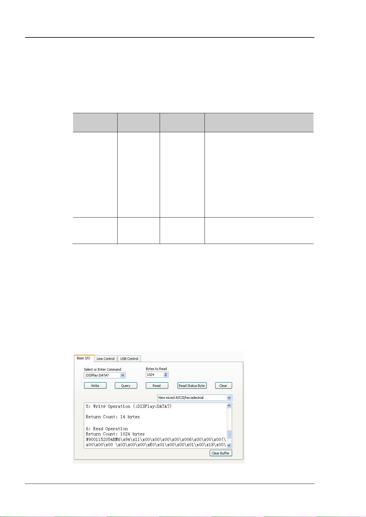
RIGOL Chapter 2 Command System
Syntax
:DISPlay:DATA?
Description
Read the bitmap data stream of the image currently displayed.
image currently displayed to the buffer area of the PC.
(length)
effective data.
of the bitmap file header.
:DISPlay:DATA?
Explanation The command is sent from the PC to the instrument through the V ISA interface. The
instrument responds to the command and directly returns the bitmap data stream of the
Return
Format
Th format of the bitmap data stream is as follows.
Component
Size
Example Explanation
TMC Blockheader ::= #NXXXXXX is
used to describe the length of the
data stream. Wherein, # is the start
denoter of the data stream; N is less
TMC
Blockheader
[1]
+2 #9001152054
N
than or equal to 9 and the N figures
following it denote the length of the
data stream in bytes. For example,
#9001152054; wherein, N is 9 and
001152054 denotes that the data
stream contains 1152054 bytes of
TMC
Blockheader
[1]
Note
: N is the width used to describe the data length in the TMC header. For example,
800*480*3+
54=1152054
[2]
BM… Specific bitmap data.
#90000.
[2]
Note
: The width is 800, the height is 480, the bit depth is 24 bit = 3 byte, 54 is the size
Example 1. Make sure that the buffer is large enough to receive the data stream, otherwise the
program might be abnormal when reading the data stream.
2. The returned data stream contains the TMC data header which should be removed to
make the data stream a standard bitmap data stream.
3. When the data size is larger than 1 M and the communication speed of the interface
is not fast enough, you need to set an approp riate timeout time.
4. The terminator '\n'(0X0A) at the end of the data should be removed.
2-30 DS1000Z Programming Guide
Page 45
Chapter 2 Command System RIGOL
:DISPlay:TYPE?
Description
Set or query the display mode of the waveform on the screen.
Name
Type
Range
Default
<type>
Discrete
{VECTors|DOTS}
VECTors
and use the cursor to measure the X and Y values of the sample point.
Format
Example
:DISPlay:TYPE DOTS
Description
Set or query the persistence time. The default unit is s.
Name
Type
Range
Default
<time>
Discrete
{MIN|0.1|0.2|0.5|1|5|10|INFinite}
MIN
as well as capture incidental events.
Format
Example
:DISPlay:GRADing:TIME 0.1 /*Set the persistence time to 0.1s*/
:DISPlay:WBRightness?
Name
Type
Range
Default
<time>
Integer
0 to 100
50
Format
Example
:DISPlay:WBRig ht nes s 60
:DISPlay:TYPE
Syntax :DISPlay:TYPE <type>
Parameter
Explanation VECTors: the sample points are connected by lines. Normally, this mode can provide
the most vivid wav eform to view th e steep edge of the wa veform ( such as the square
waveform).
DOTS: display the sample points directly. You can directly view each sample point
Return
The query returns VECT or DOTS.
:DISPlay:GRADing:TIME
Syntax :DISPlay:GRADing:TIME <time>
:DISPlay:GRADing:TIME?
Parameter
Explanation MIN: set the persis tence time to i ts mini mum to v iew the w av ef orm chang ing in h igh
refresh rate.
Specific Values: set the persistence time to one of the values listed above to observe
glitch that changes relatively slowly or glitch with low occurrence probability.
INFinite: in this mode, the oscilloscope displa ys the newly acquired waveform
without clearing the waveform fo rmerly acqu ired. Enable to measure noise an d jitter
Return
The query returns the persistence time currently set.
:DISPlay:WBRightness
Syntax :DISPlay:WB Ri g htne ss <ti m e>
Description Set or query the waveform brightness. The default unit is %.
Parameter
Return
DS1000Z Programming Guide 2-31
The query returns an integer between 0 and 100.
Page 46
RIGOL Chapter 2 Command System
:DISPlay:GRID?
Description
Set or query the grid type of screen display.
Name
Type
Range
Default
<grid>
Discrete
{FULL|HALF|NONE}
FULL
NONE: turn the background grid and coordinate off.
Format
:DISPlay:GBRightness?
Description
Set or query the bri ghtness of the screen grid. The default unit is %.
Name
Type
Range
Default
Format
Example
:DISPlay:GBRightness 60
:DISPlay:GRID
Syntax :DISPlay:GR ID <grid>
Parameter
Explanation FULL: turn the background grid and coordinate on.
HALF: turn the background grid o ff.
Return
The query returns FULL, HALF or NONE.
Example :DISPlay:GR ID NO NE
:DISPlay:GBRightness
Syntax :DISPlay:GBR ightness <brightness >
Parameter
<brightness> Integer 0 to 100 50
Return
The query returns an integer between 0 and 100.
2-32 DS1000Z Programming Guide
Page 47
Chapter 2 Command System RIGOL
Syntax
*CLS
Description
Clear all the event registers in the register set and clear the error queue.
*ESE?
Description
Set or query the enable register for the standard event status register set.
Name
Type
Range
Default
<value>
Integer
0 to 255
0
and of which the bit 1 and bit 6 are 0.
Format
already been set in the register.
*ESE? /*The query returns 16*/
IEEE488.2 Common Commands
The IEEE 488.2 standard defines some common commands used for quer ying the basic information of the
instrument or executing the basic operations. These commands usually start with "*" and the keyword of
the command is usually 3-character long.
Command List:
*CLS
*ESE
*ESR?
*IDN?
*OPC
*RST
*SRE
*STB?
*TST?
*WAI
*CLS
*ESE
Syntax *ESE <value>
Parameter
Explanation The bit 1 and bit 6 of the standard event status register are not used and are always
treated as 0, therefore, the range of <value> are the decimal numbers corresponding to
the binary numbers ranging from 00000000 (0 in deci mal) to 11111111 (255 in decimal)
Return
Example *ESE 16 /*Enable the bit 4 (16 in decimal) of the standard event status register */
The query returns an integer which equals the sum of the weights of all the bits that have
DS1000Z Programming Guide 2-33
Page 48
RIGOL Chapter 2 Command System
Syntax
*ESR?
Description
Query and clear the event register for the standard event status register.
and of which the b it 1 and bit 6 ar e 0.
Format
Syntax
*IDN?
Description
Query the ID string of the instrument.
Format
TECHNOLOGIES,DS1104Z,DS1T00000006,00.02.00.
*OPC
status register to 1 after the current operation is finished.
Syntax
*RST
Description
Restore the instrument to the default state.
*SRE?
Description
Set or query the enable register for the status byte register set.
Name
Type
Range
Default
<value>
Integer
0 to 255
0
which the bit 0 and bit 1 are 0.
Format
have already been set in the register.
*SRE? /*The query returns 16*/
*ESR?
Explanation The bit 1 and bit 6 of the standard event status register are not used and are always
treated as 0. The range of the return value are the decimal numbers corresponding to
the binary numbers ranging from 00000000 (0 in decimal) to 11111111 (255 in decimal)
Return
The query returns an integer between 0 and 255.
*IDN?
Return
The query returns the ID string of the instrument, such as RIGOL
*OPC
Syntax *OPC?
Description The *OPC? command is used to query whe ther the current operation is finished . The
*OPC command is used to set the Operation Complete bit (bit 0) in the standard event
Return
Format
The query returns 1 if the current operation is finished; otherwise, returns 0.
*RST
*SRE
Syntax *SRE <value>
Parameter
Explanation The bit 0 and bit 1 of the status byte register are not used and are always treated as 0,
therefore, the range of <value> are the decimal numbers corresponding to the binary
numbers ranging from 00000000 (0 in decimal) to 11111111 (255 in decimal) and of
Return
Example *SRE 16 /*Enable the bit 4 (16 in decimal) of the status byte register*/
2-34 DS1000Z Programming Guide
The query returns a n i nteger which equals the sum of the weights of all the bits that
Page 49

Chapter 2 Command System RIGOL
Syntax
*STB?
register for the status byte r egis ter. The value of the statu s by te register
is set to 0 after this command is executed.
1 are 0.
Format
Syntax
*TST?
Description
Perform a self-test and then returns the seilf-test results.
Format
Syntax
*WAI
Description
Wait for the operation to finish.
*STB?
Description Query the event
Explanation The bit 0 and bit 1 of the status byte register are not used and are always treated as 0.
The query returns the decimal numbers corresponding to the binary numbers ranging
from 00000000 (0 in decimal) to 11111111 (255 in decimal) and of which the bit 0 and bit
Return
The query returns an integer between 0 and 255.
*TST?
Return
The query returns a decimal integer.
*WAI
Explanation The subsequent command can only be carried out aft er the current command has been
executed.
DS1000Z Programming Guide 2-35
Page 50

RIGOL Chapter 2 Command System
:MATH Commands
The :MATH commands are used to set the operations between the waveforms of multiple channels.
Note:
The operations can be divided into two types.
Analog Operations: A+B, A-B, A×B, A/B, FFT, intg, diff, sqrt, lg, ln, exp and abs
Logic Operation: A&&B, A||B, A^B and !A
For the logic operation, the waveform data to be operated is compared with the preset threshold and is
converted to 0 or 1. Thus, the result will also be 0 or 1.
For the anal og operation or logic operation which needs only one source, only the
command will be used.
Command List:
:MATH:DISPlay
:MATH:OPERator
:MATH:SOURce1
:MATH:SOURce2
:MATH:SCALe
:MATH:SOURce1
:MATH:OFFSet
:MATH:INVert
:MATH:RESet
:MATH:FFT:WINDow
:MATH:FFT:SPLit
:MATH:FFT:UNIT
:MATH:FFT:HSCale
:MATH:FFT:HCENter
:MATH:OPTion:STARt
:MATH:OPTion:END
:MATH:OPTion:INVert
:MATH:OPTion:SENSitivity
:MATH:OPTion:DIStance
:MATH:OPTion:ASCale
:MATH:OPTion:THReshold1
:MATH:OPTion:THReshold2
2-36 DS1000Z Programming Guide
Page 51
Chapter 2 Command System RIGOL
:MATH:DISPlay?
Description
Enable or disable the math operation function or query the math operation status.
Name
Type
Range
Default
<bool>
Bool
{{0|OFF}|{1|ON}}
0|OFF
Format
:MATH:OPERator?
Description
Set or query the operator of the math operation.
Name
Type
Range
Default
Format
LOG, LN, EXP or ABS.
Example
:MATH:OPERator INTG
:MATH:SOURce1?
Description
Set or query the source of the math operation.
Name
Type
Range
Default
<src>
Discrete
{CHANnel1|CHANnel2|CHANnel3|CHANnel4}
CHANnel1
For the operations which needs two sources, this command is used to set source A.
Format
Example
:MATH:SOURce1 CHANnel3
:MATH:DISPlay
Syntax :MATH:DI SPl ay <bool>
Parameter
Return
Example
The query returns 0 or 1.
:MATH:DISPlay ON
:MATH:OPERator
Syntax :MATH:OPERator <opt>
Parameter
<opt> Discrete {ADD|SUBTract|MULTiply|DIVision|AND|OR|XOR|
Return
The query returns ADD, SUBT, MULT, DIV, AND, OR, XOR, NOT, FFT, INTG, DIFF, SQRT,
:MATH:SOURce1
Syntax :MATH:SOURce1 <src>
ADD
NOT|FFT|INTG|DIFF|SQRT|LOG|LN|EXP|ABS}
Parameter
Explanation For the operations which nee ds only one source, just this command will be used.
Return
The query returns CHAN1, CHAN2, CHAN3 or CHAN4.
DS1000Z Programming Guide 2-37
Page 52
RIGOL Chapter 2 Command System
:MATH:SOURce2?
Description
Set or query the source of the math op eration.
Name
Type
Range
Default
<src>
Discrete
{CHANnel1|CHANnel2|CHANnel3|CHANnel4}
CHANnel1
to set source B.
Format
Example
:MATH:SOURce2 CHANnel3
:MATH:SCALe?
currently selected and the unit of the source.
Name
Type
Range
Default
is also related to the current horizontal timebase.
Format
:MATH:SCALe? /*The query returns 2.000000e+00*/
:TIMebase[:MAIN]:SCALe
:MATH:SOURce2
Syntax :MATH:SOURce2 <src>
Parameter
Explanation This command is only applicable to the operations which needs two source and it is used
Return
The query returnsCHAN1, CHAN2, CHAN3 or CHAN4.
:MATH:SCALe
Syntax :MATH:SCALe <scale>
Description Set or query the vertical scale of the operation result. The unit depends on the operator
Parameter
<scale> Real The max range is from 1p to 5T (in 1-2-5 step) 1.00V
Explanation The range of the vertical scale is related to the oper ator cu rrently select ed and the vertic al
scale of the source channel. For the integration (intg) and differential (diff) operations, it
Return
Example
The query returns the vertical scale of the operation result in scientif ic notation .
:MATH:SCALe 2 /*Set the vertical scale to 2*/
Related
Commands
:CHANnel<n>:SCALe
:CHANnel<n>:UNITs
:MATH:OPERator
2-38 DS1000Z Programming Guide
Page 53
Chapter 2 Command System RIGOL
:MATH:OFFSet?
Name
Type
Range
Default
Step: MathVerticalScale/50
Format
:MATH:OFFSet? /*The query returns 8.000000e+00*/
:CHANnel<n>:UNITs
:MATH:INVert?
display mode status of the operation result.
Name
Type
Range
Default
This command has the same function as the :MATH:OPTion:INVert command.
Format
Example
:MATH:INVert ON
Syntax
:MATH:RESet
the source.
:TIMebase[:MAIN]:SCALe
:MATH:OFFSet
Syntax :MATH:OFFSet <offs>
Description Set or query the vertical offset of the operation result. The unit depends on the operator
currently selected and the unit of the source.
Parameter
Related to the vertical scale of the operation result.
<offs> Real
Explanation MathVerticalScale is the vertical scale of the operation result and can be set by
:MATH:SCALe command.
the
Range: -1000*MathVerticalScale to
1000*MathVerticalScale
0.00V
Return
Example
Related
Commands
The query returns the vertical offset of the operation result in scientific notation.
:MATH:OFFSet 8 /*Set the vertical offset to 8V*/
:MATH:OPERator
:MATH:SCALe
:MATH:INVert
Syntax :MATH:INVert <bool>
Description Enable or disable the inverted display mode of the operation result, or query the inverted
Parameter
<bool> Bool {{0|OFF}|{1|ON}} 0|OFF
Explanation This command is invalid for the FFT operation.
Return
The query returns 0 or 1.
Related
Commands
:MATH:OPERator
:MATH:OPTion:INVert
:MATH:RESet
Description Sending this command, the instrument adjusts the vertical scale of the operation result to
the most proper value according to the current operator and the horizontal timebase of
Related
Commands
DS1000Z Programming Guide 2-39
:MATH:OPERator
:MATH:SCALe
Page 54
RIGOL Chapter 2 Command System
:MATH:FFT:WINDow?
Description
Set or query the wi ndow function of the FFT operation.
Name
Type
Range
Default
FLATtop|TRIangle}
characteristics.
Format
Example
:MATH:FFT:WINDow BLACkman
:MATH:FFT:SPLit?
of the half display mode of the FFT operation.
Name
Type
Range
Default
<bool>
Bool
{{0|OFF}|{1|ON}}
1|ON
frequency spectrum more clearly and to perform more precise measurement.
Format
Example
:MATH:FFT:SPLit OFF
Command
:MATH:FFT:WINDow
Syntax :MATH:FFT:WINDow <wnd>
Parameter
<wnd> Discrete
{RECTangle|BLACkman|HANNing|HAMMing|
RECTangle
Explanation Spectral leakage can be considerably decreased when a wi ndow function is used.
Different window functions are applicable to measure different wav ef orms. You need
to select the window function according to wa veform to be measured and its
Return
Related
Command
The query returns RECT, BLAC, HANN, HAMM, FLAT or TRI.
:MATH:OPERator
:MATH:FFT:SPLit
Syntax :MATH:FFT:SPLit <bool >
Description Enable or disable the half-screen display mode of the FFT operation, or query the status
Parameter
Explanation Enable the half-screen display mode: the source channel and the FFT operation
results are displayed separately. The time domain and frequency domain signals are
displayed clearly.
Disable the half-screen display mode (full-screen display mode): the source channel
and the FFT operation results are displayed in the same window to view the
Return
Related
The query returns 0 or 1.
:MATH:OPERator
2-40 DS1000Z Programming Guide
Page 55
Chapter 2 Command System RIGOL
:MATH:FFT:UNIT?
Description
Set or query the vertical unit of the FFT operation result.
Name
Type
Range
Default
<unit>
Discrete
{VRMS|DB}
DB
Format
Example
:MATH:FFT:UNIT VRMS
:MATH:FFT:HSCale?
Description
Set or query the horizontal scale of the FFT operation result. The default unit is Hz.
Name
Type
Range
Default
scale.
Format
:MATH:FFT:HSCale? /*The query returns 5.000000e+05*/
:TIMebase[:MAIN]:SCALe
:MATH:FFT:UNIT
Syntax :MATH:FFT:UNIT <unit>
Parameter
Return
Related
Command
The query returns DB or VRMS.
:MATH:OPERator
:MATH:FFT:HSCale
Syntax :MATH:FFT:HSCale <hsc>
Parameter
<hsc>
Real
Explanation <hsc> can be set to 1/20, 1/40, 1/100 and 1/200 of the current screen sample rate
(current screen sample rate=100/current horizontal timebase).
For example, if the horizontal timebase of the instrument is 1μs, the current screen
sample rate is 100/1μs=100MHz. Thus, the horizontal scale can be set to 5MHz,
2.5MHz, 1MHz or 500kHz.
You can view the detailed information of the spectrum by reducing the horizontal
Refer to Explanation
5.00MHz
Return
Example
Related
Commands
The query returns the horizontal scale in scientific notation.
:MATH:FFT:HSCale 500000 /*Set the horizontal scale to 500kHz*/
:MATH:OPERator
DS1000Z Programming Guide 2-41
Page 56
RIGOL Chapter 2 Command System
:MATH:FFT:HCENter?
Name
Type
Range
Default
<cent>
Real
0 to (current screen sample rate×2/5)
5MHz
Step = horizontal scale of the FFT operation result/50.
Format
:MATH:FFT:HCENter? /*The query returns 1.000000e+07*/
:MATH:OPTion:STARt?
Description
Set or query the start point of the waveform math operation.
Name
Type
Range
Default
the leftmost is 0 and the rightmost is 1199.
Format
Example
:MATH:OPTion:STARt 50
Command
:MATH:FFT:HCENter
Syntax :MATH:FFT:HCENter <cent>
Description Set or query the center frequency of the FFT operation result, namely the frequency
relative to the horizontal center of the screen. The default unit is Hz.
Parameter
Explanation Current screen sample rate = 100/current horizontal timebase.
Return
Example
Related
Commands
The query returns the current center frequency in scientific notation.
:MATH:FFT:HCENter 10000000 /*Set the center frequency to 10MHz*/
:MATH:OPERator
:MATH:FFT:HSCale
:TIMebase[:MAIN]:SCALe
:MATH:OPTion:STARt
Syntax :MATH:OPTion:STARt <sta>
Parameter
<sta>
Integer
Explanation This command is invalid for the FFT operation. Sending this command will modify the
start points of all the operations (except FFT).
The horizontal axis of the source selected is equally divided into 1200 parts, in which
0 to (End point currently set-1)
0
Return
Related
The query returns an integer.
:MATH:OPTion:END
2-42 DS1000Z Programming Guide
Page 57
Chapter 2 Command System RIGOL
:MATH:OPTion:END?
Description
Set or query the end point of the waveform math operation.
Name
Type
Range
Default
the leftmost is 0 and the rightmost i s 1199.
Format
Example
:MATH:OPTion:END 200
Command
:MATH:OPTion:INVert?
display mode status of the operation result.
Name
Type
Range
Default
<bool>
Bool
{{0|OFF}|{1|ON}}
0|OFF
This command has the same function as the :MATH:INVert command.
Format
Example
:MATH:OPTion:INVert ON
Command
:MATH:OPTion:END
Syntax :MATH:OPTion:END <end>
Parameter
<end>
Discrete
(Start point curre ntly set+1) to 1199
1199
Explanation This command is invalid for the FFT operation. Sending this command will modify the
end points of all the operations (except FFT).
The horizontal axis of the source selected is equally divided into 1200 parts, in which
Return
Related
The query returns an integer.
:MATH:OPTion:STARt
:MATH:OPTion:INVert
Syntax :MATH:OPTion:INVert <bool>
Description Enable or disable the inverted display mode of the operation result, or query the inverted
Parameter
Explanation This command is invalid for the FFT operation. Sending this command will modify the
inverted display mode status of all the operations (except FFT).
Return
Related
The query returns 0 or 1.
:MATH:INVert
DS1000Z Programming Guide 2-43
Page 58
RIGOL Chapter 2 Command System
:MATH:OPTion:SENSitivity?
Name
Type
Range
Default
Explanation
This command is only applicable to the logic operations (A&&B, A||B, A^B and !A).
Return Format
The query returns the sensitivity in scientific notation.
:MATH:OPTion:SENSitivity? /*The query returns 2.400000e-01*/
Description
Set or query the smoothing window width of the differential operation (diff).
Name
Type
Range
Default
Explanation
This command is only applicable to the differential operation (diff).
Return Format
The query returns an integer between 3 and 201.
Command
:MATH:OPTion:ASCale?
the auto scale setting.
Sending this command will modify the auto scale status of all the operations.
Return Format
The query returns 0 or 1.
Example
:MATH:OPTion:ASCale ON
:MATH:OPTion:SENSitivity
Syntax :MATH:OPTion:SENSitivity <sens>
Description Set or query the sensitivity of the logic operation. The default unit is div (namely the
current vertical scale).
Parameter
<sens>
Real
Example :MATH:OPTion:SENSitivity 0.24 /*Set the sensitivity to 0.24div*/
Related
Commands
:CHANnel<n>:SCALe
:MATH:OPERator
:MATH:OPTion:DIStance
Syntax :MATH:OPTion:DIStance <dist>
:MATH:OPTion:DIStance?
Parameter
<dist>
Example :MATH:OPTion:DIStance 25
Integer
0 to 0.96div, the step is 0.08div
3 to 201
0
3
Related
:MATH:OPERator
:MATH:OPTion:ASCale
Syntax :MATH:OPTion:ASCale <op t >
Description Enable or disable the auto scale setting of the operation result or query the status of
Parameter
Explanation When the auto scale is enab led, the instrument will automatically calculate the
Name Type Range Default
<opt>
Bool
{{0|OFF}|{1|ON}}
vertical scale range according to the c urrent operator, the vertical scale and the
horizontal timebase. If the current scale is out of the range, it will adjust the
vertical scale to the best value automatically.
0|OFF
2-44 DS1000Z Programming Guide
Page 59
Chapter 2 Command System RIGOL
:MATH:OPTion:THReshold1?
Description
Set or query the threshold level of source A in the logic op eration. The default unit is V.
Name
Type
Range
Default
The step is Vertical Scale/25
Format
:MATH:OPTion:THReshold1? /*The query returns 8.000000e-01*/
:CHANnel<n>:OFFSet
:MATH:OPTion:THReshold2?
Description
Set or query the threshold level of source B in the logic operation. The default unit is V.
Name
Type
Range
Default
The step is Vertical Scale/25
Format
Example
:MATH:OPTion:THReshold2 0.5
:MATH:OPTion:THReshold1
Syntax :MATH:OPTion:THReshold1 <thre>
Parameter
<thre> Real
(-4*Vertical Scale – Vertical Offset) to
(4*Vertical Scale – Vertical Offset)
0.00V
Explanation This command is only applicable to the logic operations (A&&B, A||B, A^B and !A).
Vertical Scale refers to the vertical scale of source A
Vetical Offset refers to the vertical offset of source A
Return
Example
Related
The query returns the threshold level in scientific notation.
:MATH:OPTion:THReshold1 0.8 /*Set the threshold level to 800mV*/
:CHANnel<n>:SCALe
Commands
:MATH:OPTion:THReshold2
Syntax :MATH:OPTion:THReshold2 <thre>
Parameter
<thre>
Real
(-4*Vertical Scale–Vertical Offset) to
(4*Vertical Scale–Vertical Offset)
0.00V
Explanation This command is only applicable to the logic operations (A&&B, A||B, A^B and !A).
Vertical Scale refers to the vertical scale of source B
Vetical Offset refers to the vertical offset of source B
Return
Related
Commands
The query returns the threshold level in scientific notation.
:CHANnel<n>:SCALe
:CHANnel<n>:OFFSet
DS1000Z Programming Guide 2-45
Page 60
RIGOL Chapter 2 Command System
:MASK:ENABle?
Description
Enable or disable the pass/fail test or query the status of the past/fail test.
Name
Type
Range
Default
<bool>
Bool
{{0|OFF}|{1|ON}}
0|OFF
timebase is set to 200ms/div or slower) as well as during waveform record.
Format
Example
:MASK:ENABle ON
:MASK Commands
The :MASK commands are used to set and query the pass/fail test parameters.
Command List:
:MASK:ENABle
:MASK:SOURce
:MASK:OPERate
:MASK:MDISplay
:MASK:SOOutput
:MASK:OUTPut
:MASK:X
:MASK:Y
:MASK:CREate
:MASK:PASSed?
:MASK:FAILed?
:MASK:TOTal?
:MASK:RESet
:MASK:ENABle
Syntax :MASK:ENA Bl e <b ool>
Parameter
Explanation The pass/fail test is invalid in the following conditions: the horizontal timebase is XY or
ROLL, in the slow sweep mode (namely when the horizontal timebase is YT, the horizontal
Return
The query returns 0 or 1.
2-46 DS1000Z Programming Guide
Page 61
Chapter 2 Command System RIGOL
:MASK:SOURce?
Description
Set or query the source of the pass/fail test.
Name
Type
Range
Default
<source>
Discrete
{CHANnel1|CHANnel2|CHANnel3|CHANnel4}
CHANnel1
the :CHANnel<n>:DISPlay command to enable the desired channel.
Format
Example
:MASK:SOURce CHANnel2
:MASK:OPERate?
Description
Run or stop the pass/fail test, or query the status of the pass/fail test.
Name
Type
Range
Default
<oper>
Discrete
{RUN|STOP}
STOP
the pass/fail test.
Format
Example
:MASK:OPERate RUN
Command
:MASK:SOURce
Syntax :MASK:SOURce <source>
Parameter
Explanation Only the channel enabled can be selected as the source. You can sent
Return
Related
Command
The query returnsCHAN1, CHAN2, CHAN3 or CHAN4.
:CHANnel<n>:DISPlay
:MASK:OPERate
Syntax :MASK:OPERate <oper>
Parameter
Explanation Before executing this command, you need to send the :MASK:ENABle co mmand to enable
Return
Related
The query returns RUN or STOP.
:MASK:ENABle
DS1000Z Programming Guide 2-47
Page 62
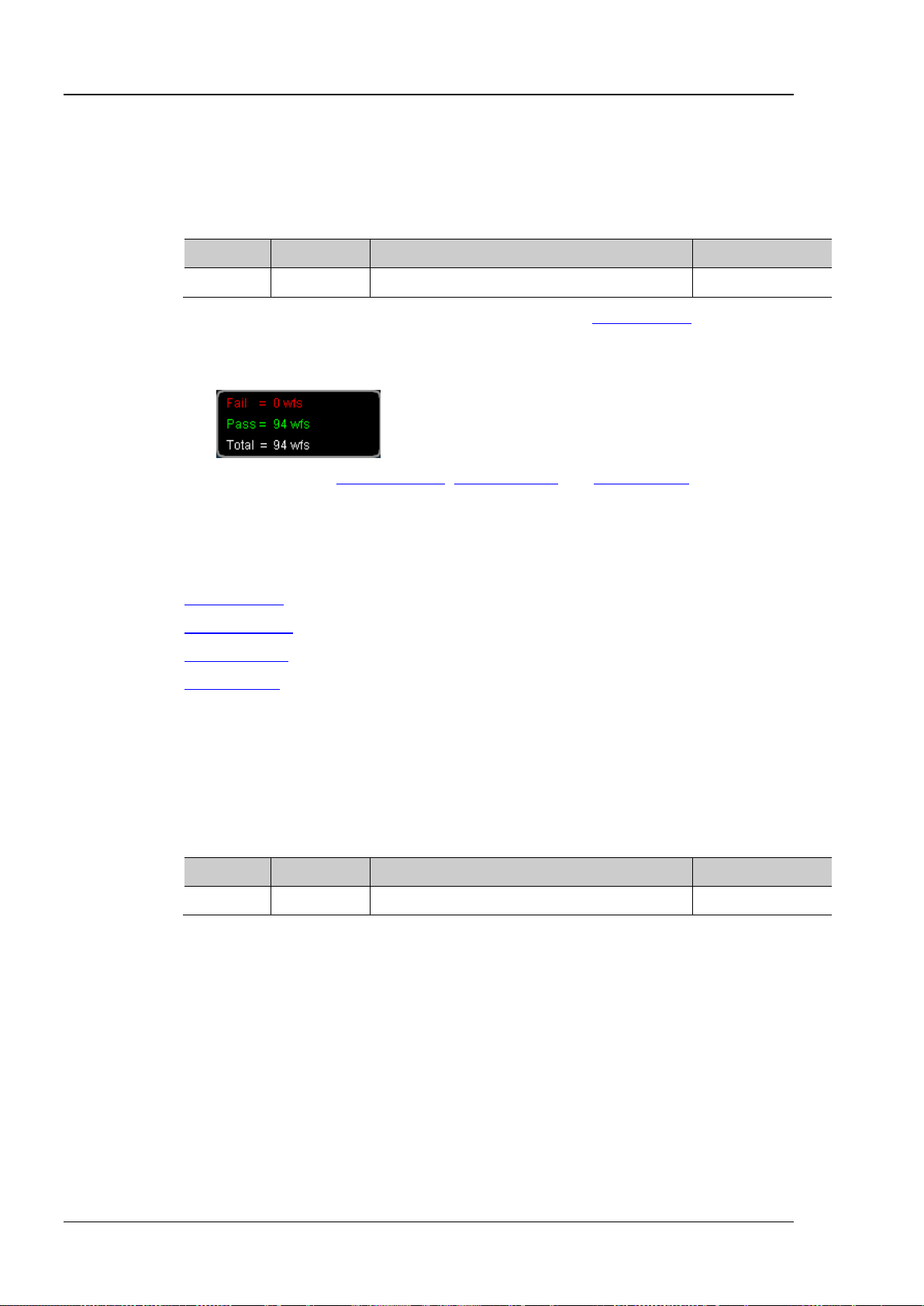
RIGOL Chapter 2 Command System
:MASK:MDISplay?
Name
Type
Range
Default
<bool>
Bool
{{0|OFF}|{1|ON}}
0|OFF
query the test results.
Format
Example
:MASK:MDISplay ON
:MASK:TOTal?
:MASK:SOOutput?
function.
Name
Type
Range
Default
<bool>
Bool
{{0|OFF}|{1|ON}}
0|OFF
detected.
Format
Example
:MASK:SOOutput ON
:MASK:MDISplay
Syntax :MASK:MDISplay <bool>
Description Enable or disable the statistic information when the pass/fail test is enabled, or query the
status of the statistic information.
Parameter
Explanation Before executing this command, you need to send the :MASK:ENABle command to
enable the pass/fail test.
When the statistic information is on, the test results as shown in the figure below will
be displayed at the upper right corner of the screen.
You can sent the
:MASK:PASSed?, :MASK:FAILed? and :MASK:TOTal? commands to
Return
Related
Commands
The query returns 0 or 1.
:MASK:ENABle
:MASK:PASSed?
:MASK:FAILed?
:MASK:SOOutput
Syntax :MASK:SOOutput <bool>
Description Turn the “Stop on Fail” function on or off, or query the status of t he “Sto p on Fail”
Parameter
Explanation ON: when failed waveforms are detected, the oscilloscope will stop the test and enter
the “STOP” state. At this p oint, th e results of th e test remain the same o n the s creen
(if the display is turned on) and the [Trigger Out] connector (if enabled) at the rear
panel outputs a single pulse.
Return
2-48 DS1000Z Programming Guide
OFF: the oscilloscope will continue with the test even t ho ugh failed waveforms are
detected. The test results on the screen will update continuously and the [Trigger
Out] connector at the rear panel outputs a pulse each time a failed waveform is
The query returns 0 or 1.
Page 63
Chapter 2 Command System RIGOL
:MASK:OUTPut?
Bool
0|OFF
beeper sounds (not related to the on/off state of the sound) .
Format
Example
:MASK:OUTPut ON
:MASK:X?
Description
Set or query the horizontal adjustment parameter in the pass/fail test mask.
Name
Type
Range
Default
Explanation
The step is 0.02 within the range.
Format
:MASK:Y?
Description
Set or query the vertical adjustment parameter in the pass/fail test mask.
Name
Type
Range
Default
<y>
Real
0.04 to 5.12
0.48
Explanation
The step is 0.04 within t he range.
Format
:MASK:Y? /*The quer y returns 3.600000e-01*/
:MASK:OUTPut
Syntax :MASK:OUTPut <bool>
Description Enable or disable the sound pro mpt when the fail ed waveforms are detec ted, or query the
status of the sound prompt.
Parameter
Name Type Range Default
<bool>
{{0|OFF}|{1|ON}}
Explanation OFF: when failed waveforms are detected, there are display and output but the
beeper does not sound.
ON: when failed waveforms are detected, there are display and output and the
Return
The query returns 0 or 1.
:MASK:X
Syntax :MASK:X <x>
Parameter
<x> Real 0.02 to 4 0.24
Return
Example
:MASK:Y
Syntax :MASK:Y <y>
Parameter
Return
Example
The query returns the horizontal adjustment parameter in scientific notation.
:MASK:X 0.28 /*Set the horizontal adjustment parameter to 0.28div*/
:MASK:X? /*The query returns 2.800000e-01*/
The query returns the vertical adjustment parameter in scientific notation.
:MASK:Y 0.36 /*Set the vertical adjustment parameter to 0.36div*/
DS1000Z Programming Guide 2-49
Page 64

RIGOL Chapter 2 Command System
Syntax
:MASK:CREate
vertical adjustment parameter.
in the run state (:MASK:OPERate).
:MASK:Y
Syntax
:MASK:PASSed?
Description
Query the number of the passed frames in the pass/fail test.
Format
Syntax
:MASK:FAILed?
Description
Query the number of the failed frames in the pass/fail test.
Syntax
:MASK:TOTal?
Description
Query the total number of the frames in the pass/fail test.
Format
Syntax
:MASK:RESet
frames in the pass/fail test to 0.
:MASK:TOTal?
:MASK:CREate
Description Create the pass/fail test mask using the current horizontal adjustment parameter and
Explanation This command is valid only when the pass/fail test is enabled (:MASK:ENABle) and is not
Related
Commands
:MASK:ENABle
:MASK:OPERate
:MASK:X
:MASK:PASSed?
Return
The query returns an integer.
:MASK:FAILed?
Return
Format
The query returns an integer.
:MASK:TOTal?
Return
The query returns an integer.
:MASK:RESet
Description Reset the numbers of the passed frames and failed frames as well asthe total number of
Related
Commands
2-50 DS1000Z Programming Guide
:MASK:PASSed?
:MASK:FAILed?
Page 65
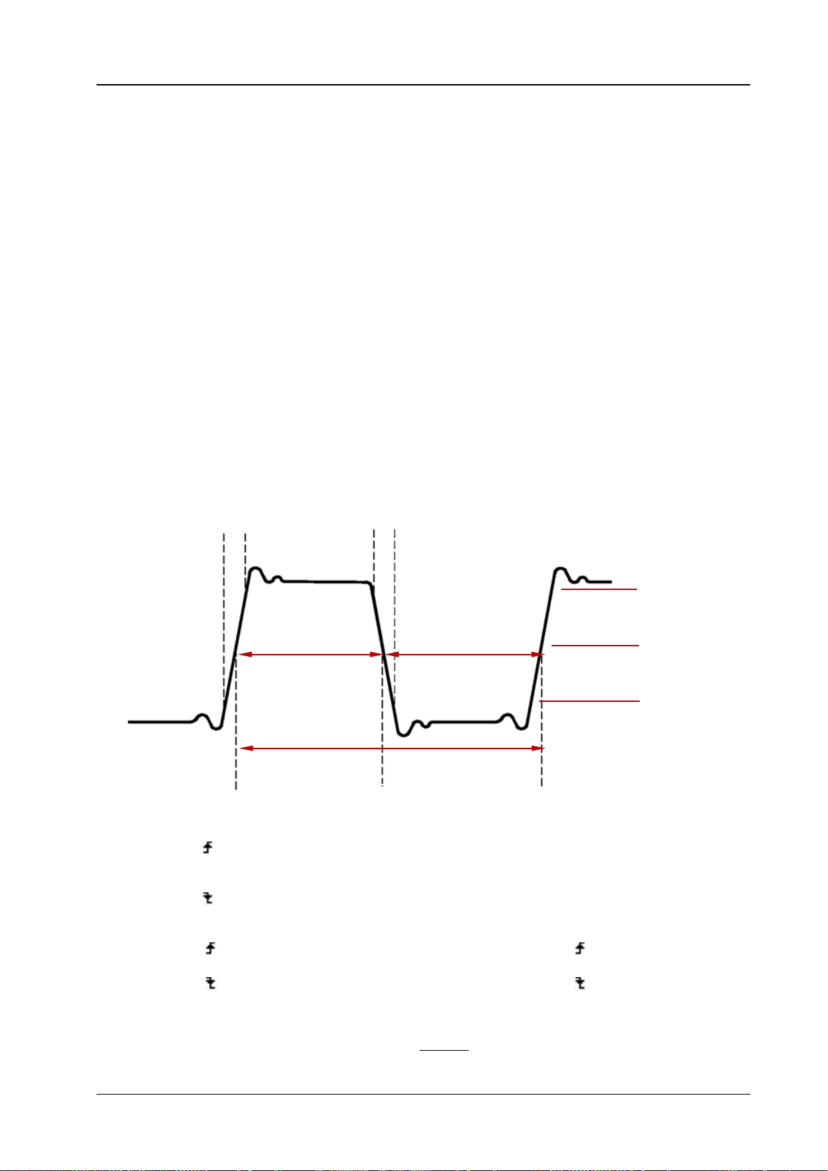
Chapter 2 Command System RIGOL
Period:
Defined as the time between the threshold middle points of two consecutive,
like-polarity edges.
Frequency:
Defined as the reciprocal of period.
Rise Time:
The time for the signal amplitude to rise from the lower limit to the upper limit of
Fall Time:
The time for the signal amplitude to fall from th e upper limit to the lower limit of the
threshod.
+ Width:
The time difference between the threshold middle points of a rising edge to the
next falling edge of the pulse.
- Width:
The time difference between the threshold middle points of a falling edge to the
next rising edge of the puls e.
+ Duty:
The ratio of the positive pulse width to the period.
- Duty:
The ratio of the negative pulse width to the period.
Delay 1→2 :
The time difference between the rising edges of source 1 and source 2. Negative
rising edge of source 2.
Delay 1→2 :
The time difference between the falling edges of source 1 and source 2. Negative
falling edge of source 2.
Phase 1→2 :
Phase difference calculated according to “Delay 1→2 ” and the period of source
1, expressed in degree. The calculation formula is as shown below.
Phase 1→2 :
Phase difference calculated according to “Delay 1→2 ” and the period of source
1, expressed in degree.The calculation formula is as shown below.
360
1
Delay
Phase
Period
= ×°
RiseTime
FallTime
Threshold Upper Limit
Threshold Middle Point
Threshold Lower Limit
+Width
-Width
Period
:MEASure Commands
DS1000Z supports the auto measurement of the following 24 waveform parameters and provide the
statistic function for the measurement results. In additional, you can use the frequency co unter to make
more precise frequency measurement. The :MEASure commands are used to set and query the
measurement parameters.
Time Parameters
the threshod.
Delay and Phase
delay indicates that the selec ted rising ed ge of source 1 occurred after the selec ted
delay indicates that the selected falling edge of source 1 occur red after the selected
DS1000Z Programming Guide 2-51
Page 66
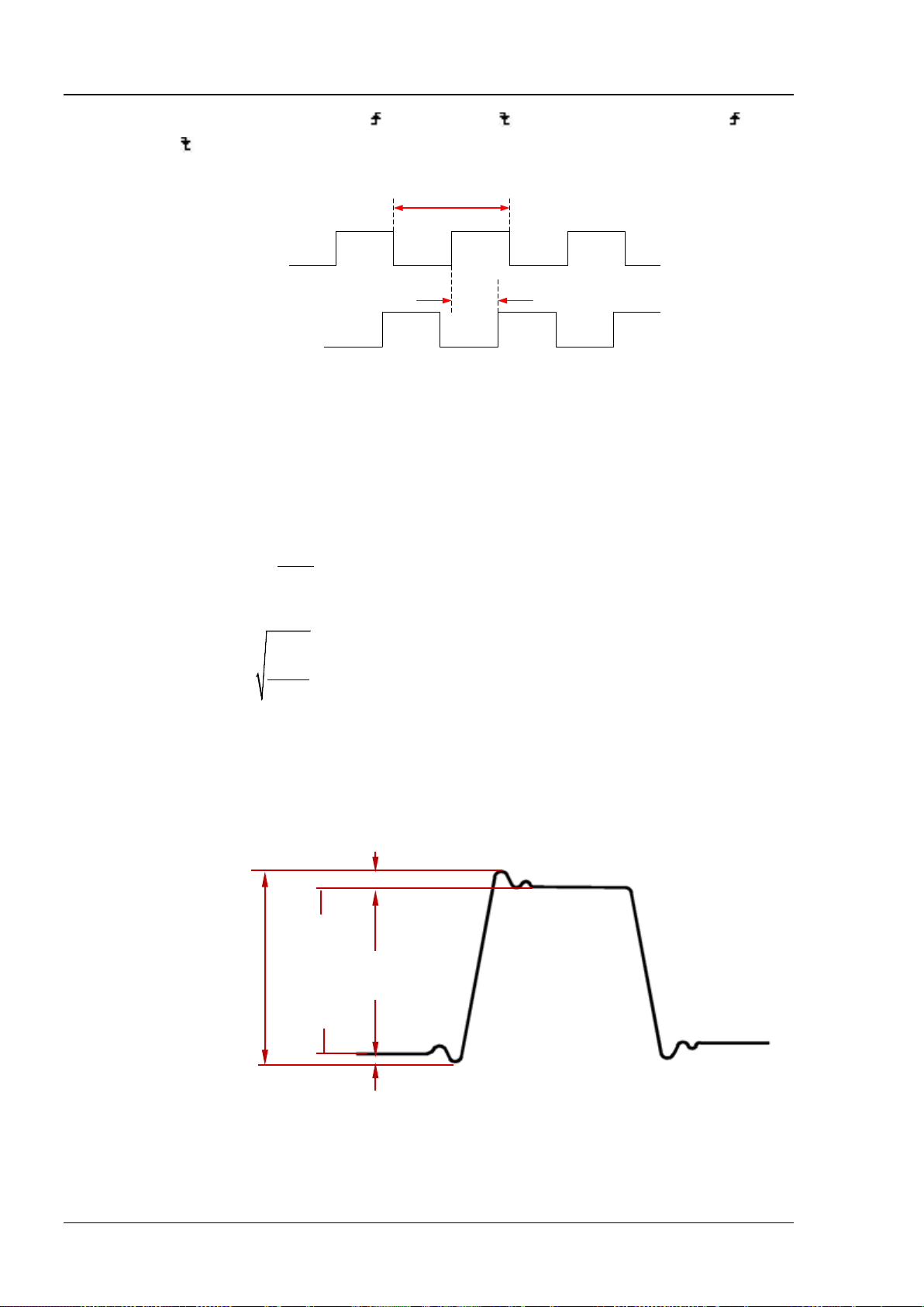
RIGOL Chapter 2 Command System
Phase
Delay
1Period
Source 1
Source 2
Period
Delay
Vmax:
the voltage value from the highest point of the waveform to the GND.
Vmin:
the voltage value from the lowest point of the waveform to the GND.
Vpp:
the voltage value from the highest point to the lowest point of the waveform.
Vtop:
the voltage value from the flat top of the waveform to the GND.
Vbase:
the voltage value from the flat base of the waveform to the GND.
Vamp:
the voltage value from the top of the waveform to the base of the waveform.
Vavg:
the arithmetic average value on the whole waveform or on the gating area.
i
x
Average
n
=
∑
i
x
ith
points being measured.
Vrms:
the root mean square value on the whole waveform or the gating area.
2
1
n
i
i
x
RMS
n
=
=
∑
i
x
ith
points being measured.
Overshoot:
the ratio of the difference between the maximum value and top value of the waveform
to the amplitude value.
Preshoot:
the ratio of the diff erence between the minimum value and base value of the waveform
to the amplitude value.
Preshoot
Overshoot
Vamp
Vmax
Vmin
Vpp
Vtop
Vbase
Wherein,
“Delay 1→2
denotes “Phase 1→2 ” or “Phase 1→2 ”,
” and
Voltage Parameters
denotes the period of source 1.
, wherein,
is the
point being measured, nis the number of
denotes “Delay 1→2 ” or
, where,
is the
point being measured, nis the number of
2-52 DS1000Z Programming Guide
Page 67

Chapter 2 Command System RIGOL
Other Parameters
Area
:
The area of the whole waveform within the screen and the unit is voltage-second. The area meadured
above the zero referenc e (n amely th e verti cal of fset) i s positi ve and the area meas ured b elow the zer o
reference is negative. The area measured is the algebraic sum of the area of the whole waveform
within the screen.
Period Area
:
The area of the first period of the waveform on the screen and the unit is voltage-second. The area
above the zero reference (namely the vertical offset) is positive and th e area below the zero referenc e
is negative. The area measured is the alg eraic sum of the area of the waveform within the whole period.
Note that when the waveform on the screen is less than a period, the period area measured is 0.
Command List:
:MEASure:SOURce
:MEASure:COUNter:SOURce
:MEASure:COUNter:VALue?
:MEASure:CLEar
:MEASure:RECover
:MEASure:ADISplay
:MEASure:AMSource
:MEASure:SETup:MAX
:MEASure:SETup:MID
:MEASure:SETup:MIN
:MEASure:SETup:PSA
:MEASure:SETup:PSB
:MEASure:SETup:DSA
:MEASure:SETup:DSB
:MEASure:STATistic:DISPlay
:MEASure:STATistic:MODE
:MEASure:STATistic:RESet
:MEASure:STATistic:ITEM
:MEASure:ITEM
DS1000Z Programming Guide 2-53
Page 68
RIGOL Chapter 2 Command System
:MEASure:SOURce?
Description
Set or query the source of the current measurement parameter.
Name
Type
Range
Default
<sour>
Discrete
{CHANnel1|CHANnel2|CHANnel3|CHANnel4}
CHANnel1
and :MEASure:SETup:PSB commands respectively.
Format
Example
:MEASure:SOURce CHANnel2
:MEASure:ITEM
:MEASure:COUNter:SOURce?
Description
Set or query the source of the frequency counter, or disable the frequency counter.
Name
Type
Range
Default
Format
Example
:MEASure:COUNter:SOURce CHANnel2
Syntax
:MEASure:COUNter:VALue?
Description
Query the measurement result of the frequency counter. The default unit is Hz.
Format
is disabled, 0.0000000e+00 will be returned.
Example
:MEASure:COUNter:VALue? /*The query retur ns 1.000004e+03*/
Command
:MEASure:SOURce
Syntax :MEASure:SOURce <sour>
Parameter
Explanation This command is used to set the source for the measurement parameters (except the
delay and phase). The delay and phase measurements requires two sources which can be
set by the
:MEASure:SETup:DSA and :MEASure:SETup:DSB, :MEASure:SETup:PSA
Return
Related
Commands
The query returns CHAN1, CHAN2, CHAN3 or CHAN4.
:MEASure:SETup:PSA
:MEASure:SETup:PSB
:MEASure:SETup:DSA
:MEASure:SETup:DSB
:MEASure:COUNter:SOURce
Syntax :MEASure:COUNter:SOUR ce <sour>
Parameter
<sour> Discrete {CHANnel1|CHANnel2|CHANnel3|CHANnel4|OFF} OFF
Return
The query returns CHAN1, CHAN2, CHAN3, CHAN4 or OFF.
Related
Command
:MEASure:COUNter:VALue?
:MEASure:COUNter:VALue?
Return
Related
2-54 DS1000Z Programming Guide
The query returns the measurement result in scientific notation. If the frequency counter
:MEASure:COUNter:SOURce
Page 69

Chapter 2 Command System RIGOL
Syntax
:MEASure:CLEar <item>
Description
Clear one or all of the last five measurement items enabled.
Name
Type
Range
Default
<item>
Discrete
{ITEM1|ITEM2|ITEM3|ITEM4|ITEM5|ALL}
--
cleared.
Example
:MEASure:CLEar ITEM1
:MEASure:ITEM
Syntax
:MEASure:RECover <item>
Description
Recover the measurement item which has been cleared.
Name
Type
Range
Default
<item>
Discrete
{ITEM1|ITEM2|ITEM3|ITEM4|ITEM5|ALL}
--
of the measurement items are recovered.
:MEASure:CLEar
Parameter
Explanation You can use the :MEASure:ITEM command to enable the desired parameters of the
24 waveform parameters. Note that the last five parameters are determined
according to the order in which you turned them on and they will not change as you
delete one or more measurement items.
:MEASure:RECover command to recover the item which has been
Related
You can send the
:MEASure:RECover
Commands
:MEASure:RECover
Parameter
Explanation You can use the :MEASure:ITEM command to enable the desired parameters of the
24 waveform parameters. Note that the last five parameters are determined
according to the order in which you turned them on and they will not change as you
delete one or more measurement items.
:MEASure:CLEar command to clear the items again after one or all
Related
Commands
You can send the
:MEASure:CLEar
:MEASure:ITEM
DS1000Z Programming Guide 2-55
Page 70

RIGOL Chapter 2 Command System
:MEASure:ADISplay?
Name
Type
Range
Default
<bool>
Bool
{{0|OFF}|{1|ON}}
0|OFF
measurement function.
Format
Example
:MEASure:ADISplay ON
Command
:MEASure:AMSource?
Description
Set or query the source of the all measurement function.
Name
Type
Range
Default
<src>
Discrete
{CHANnel1|CHANnel2|CHANnel3|CHANnel4}
CHANnel1
Format
:MEASure:ADISplay
Syntax :MEASure :ADI Spl ay <bool>
Description Enable or disable the all measurement function, or query the status of the all
measurement function.
Parameter
Explanation The all measurement function can measure the following 20 parameters of the
source at the same time:
Voltage Parameters: Vmax, Vmin, Vpp, Vtop, Vbase, Vamp, Vavg, Vrms, Overshoot
and Peshoot
Time Parameters: Period, Frequency, Rise Time, Fal l Time , + Width, - Width, + Duty
and - Duty
Other Parameters: Area and Period Area.
The all measurement function can measure CH1, CH2, CH3 and CH4 at the same
time. You can send the
:MEASure:AMSource command to set the source of the all
Return
Related
The query returns 0 or 1.
:MEASure:AMSource
:MEASure:AMSource
Syntax :MEASure:AMSource <src>[,<src>[,<src>[,<src>]]]
Parameter
Return
Example
The query returns CHAN1, CHAN2, CHAN3 or CHAN4.
:MEASure:AMSource CHANnel1,CHANnel3
2-56 DS1000Z Programming Guide
Page 71
Chapter 2 Command System RIGOL
:MEASure:SETup:MAX?
Name
Type
Range
Default
middle point to keep it lower than the upper limit.
Format
Example
:MEASure:SETup:MAX 95
:MEASure:ITEM
measurements. The default unit is %.
Name
Type
Range
Default
<value>
Integer
6 to 94
50
The middle point must be lower than the upper limit and greater than the lower limit.
Format
Example
:MEASure:SETup:MID 89
:MEASure:ITEM
:MEASure:SETup:MAX
Syntax :MEASure :SE Tup :MAX <va l ue>
Description Set or query the upper limit of the threshold in the time, delay and phase measurements.
The default unit is %.
Parameter
<value> Integer 7 to 95 90
Explanation The upper limit, middle point and lower limit of the threshold (expressed in %) are
used to define the time, delay and phase p arameters. S ettin g these v alues will aff ect
the measurement results of the time, delay and phase parameters.
Setting the upper limit lower than the middle point will automatically reduce the
Return
Related
Commands
The query returns an integer between 7 and 95.
:MEASure:SETup:MID
:MEASure:SETup:MIN
:MEASure:SETup:MID
Syntax :MEASure :SE Tup :MID < val ue>
:MEASure:SETup:MID?
Description
Parameter
Explanation The upper limit, middle point and lower limit of the threshold (expressed in %) are
Set or query the middle point of the threshold in the time, delay and phase
used to define the time, delay and ph ase par ameters. S et ting th ese v al ues will affect
the measurement results of the time, delay and phase parameters.
Return
Related
Commands
The query returns an integer between 6 and 94.
:MEASure:SETup:MAX
:MEASure:SETup:MIN
DS1000Z Programming Guide 2-57
Page 72

RIGOL Chapter 2 Command System
:MEASure:SETup:MIN?
Name
Type
Range
Default
<value>
Integer
5 to 93
10
used to define the time, delay and ph ase par ameters. S et ting th ese v al ues will aff ect
middle point to keep it greater than the upper limit.
Format
Example
:MEASure:SETup:MIN 93
:MEASure:ITEM
:MEASure:SETup:PSA?
Name
Type
Range
Default
Format
Example
:MEASure:SETup:PSA CHANnel1
Command
:MEASure:SETup:MIN
Syntax :MEASure :SE Tup :MIN < val ue>
Description Set or query the lower limit of the threshold in the time, delay and phas e measu remen ts.
The default unit is %.
Parameter
Explanation The upper limit, middle point and lower limit of the threshold (expressed in %) are
the measurement results of the time, delay and phase parameters.
Setting the lower limit greater than the middle point will automatically increase the
Return
Related
Commands
The query returns an integer between 5 and 93.
:MEASure:SETup:MAX
:MEASure:SETup:MID
:MEASure:SETup:PSA
Syntax :MEASure:SETup:PSA <source>
Description
Parameter
Return
Related
Set or query sou rce A of the Phase 1→2
<source>
Discrete
The query returns CHAN1, CHAN2, CHAN3 or CHAN4.
:MEASure:ITEM
and Pha se 1→2 measurements.
{CHANnel1|CHANnel2|CHANnel3|CHANnel4}
CHANnel1
2-58 DS1000Z Programming Guide
Page 73
Chapter 2 Command System RIGOL
:MEASure:SETup:PSB?
Set or query source B of the Phase 1→2 and Phase 1→2 measurements.
Name
Type
Range
Default
Format
Example
:MEASure:SETup:PSB CHANnel1
:MEASure:SETup:DSA?
Name
Type
Range
Default
<source>
Discrete
{CHANnel1|CHANnel2|CHANnel3|CHANnel4}
CHANnel1
Format
Example
:MEASure:SETup:DSA CHANnel1
Command
:MEASure:SETup:DSB?
Name
Type
Range
Default
Format
Example
:MEASure:SETup:DSB CHANnel1
Command
:MEASure:SETup:PSB
Syntax :MEASure:SETup:PSB <source>
Description
Parameter
Return
Related
Command
<source>
The query returns CHAN1, CHAN2, CHAN3 or CHAN4.
:MEASure:ITEM
Discrete
:MEASure:SETup:DSA
Syntax :MEASure:SETup:DSA <source>
Description
Parameter
Return
Related
Set or query sou rce A of the Delay 1→2
The query returns CHAN1, CHAN2, CHAN3 or CHAN4.
:MEASure:ITEM
{CHANnel1|CHANnel2|CHANnel3|CHANnel4}
and Delay 1→2 measurements.
CHANnel2
:MEASure:SETup:DSB
Syntax :MEASure:SETup:DSB <source>
Description
Parameter
Return
Related
Set or query source B of the Delay 1→2
<source>
Discrete
The query returns CHAN1, CHAN2, CHAN3 or CHAN4.
:MEASure:ITEM
and Delay 1→2 measurements.
{CHANnel1|CHANnel2|CHANnel3|CHANnel4}
CHANnel2
DS1000Z Programming Guide 2-59
Page 74

RIGOL Chapter 2 Command System
:MEASure:STATistic:DISPlay?
Description
Enable or disable the statistic function, or query the status of the statistic function.
Name
Type
Range
Default
<bool>
Bool
{{0|OFF}|{1|ON}}
0|OFF
statistic results of at most 5 measurement items that are turned on last.
Format
Example
:MEASure:STATistic:DISPlay ON
:MEASure:ITEM
:MEASure:STATistic:MODE?
Description
Set or query the statistic mode.
Name
Type
Range
Default
<mode>
Discrete
{DIFFerence|EXTRemum}
EXTRemum
the statistic results of at most 5 measurement items that are turned on last.
Format
:MEASure:STATistic:MODE? /*The query returns DIFF*/
:MEASure:STATistic:DISPlay
Syntax :MEASure:STATistic:DISPlay <bool>
Parameter
Explanation When the statistic function is enabled, the oscilloscope makes statistic and displays the
Return
Related
Commands
The query returns 0 or 1.
:MEASure:STATistic:MODE
:MEASure:STATistic:RESet
:MEASure:STATistic:ITEM
:MEASure:STATistic:MODE
Syntax :MEASure:STATistic:MODE <mode>
Parameter
Explanation DIFFerence: select the difference mode. The statistic results contain the current
value, average value, standard deviation and counts.
EXTRemum: select the extremum mode. The statistic results contain the current
value, average value, minimum and maximum.
Sending the
:MEASure:STATistic:DISPlay command can enable the statistic function.
When the statistic function is enabled, the oscilloscope makes statistic and displays
Return
Example
Related
Commands
The query returns DIFF or EXTR.
:MEASure:STATistic:MODE DIFFerence /*Select the difference mode*/
:MEASure:STATistic:DISPlay
:MEASure:STATistic:RESet
:MEASure:STATistic:ITEM
2-60 DS1000Z Programming Guide
Page 75
Chapter 2 Command System RIGOL
Syntax
:MEASure:STATistic:RESet
Description
Clear the history data and make statistic again.
:MEASure:STATistic:ITEM? <type>,<item>[,<src>[,<src>]]
the statistic result of any waveform parameter of the specified source.
RPHase|FPHase}
DEViation}
and :MEASure:SETup:PSB commands by default.
Format
:MEASure:STATistic:ITEM? MAXimum,VPP /*The query returns 9.120000e-01*/
:MEASure:SETup:PSB
:MEASure:STATistic:RESet
Related
Commands
:MEASure:STATistic:DISPlay
:MEASure:STATistic:MODE
:MEASure:STATistic:ITEM
:MEASure:STATistic:ITEM
Syntax :MEASure:STATistic:ITEM <item>[,<src>[,<src>]]
Description Enable the statistic function of any waveform parameter of the specified source, or query
Parameter
Name Type Range Default
{VMAX|VMIN|VPP|VTOP|VBASe|VAMP|VAVG|
VRMS|OVERshoot|PREShoot|MARea|MPARea|
<item> Discrete
PERiod|FREQuency|RTIMe|FTIMe|PWIDth|
--
NWIDth|PDUTy|NDUTy|RDELay|FDELay|
<src> Discrete {CHANnel1|CHANnel2|CHANnel3|CHANnel4}
Refer to
Explanation
<type> Discrete
{MAXimum|MINimum|CURRent|AVERages|
Explanation [,<src>[,<src>]] sets the source of the parameter to be measured.
If the parameter to be measured only needs a single source (such as VMAX, VMIN,
VPP, VTOP, VBASe, VAMP, VAVG, VRMS, OVERshoot, MARea, MPARea, PREShoot,
PERiod, FREQuency, RTIMe, FTIMe, PWIDth, NWIDth, PDUTy and NDUTy), you only
need to set one source. If [,<src>[,<src>]] is omitted, the source is the one selected
by the
:MEASure:SOURce command by default.
If the parameter to be measured needs two sources (such as RDELay, FDELay,
RPHase and FPHase), the command needs to include two sources; otherwise, the
command is invalid. If [,<src>[,<src>]] is omitted, the sources are th e ones selected
:MEASure:SETup:DSA and :MEASure:SETup:DSB or :MEASure:SETup:PSA
Return
Example
Related
Commands
by the
The query returns the statistic result in scientific notation.
:MEASure:STATistic:ITEM VPP,CHANnel2 /*Enable the Vpp statistic function of CH2*/
:MEASure:SOURce
:MEASure:SETup:DSA
:MEASure:SETup:DSB
--
:MEASure:SETup:PSA
DS1000Z Programming Guide 2-61
Page 76
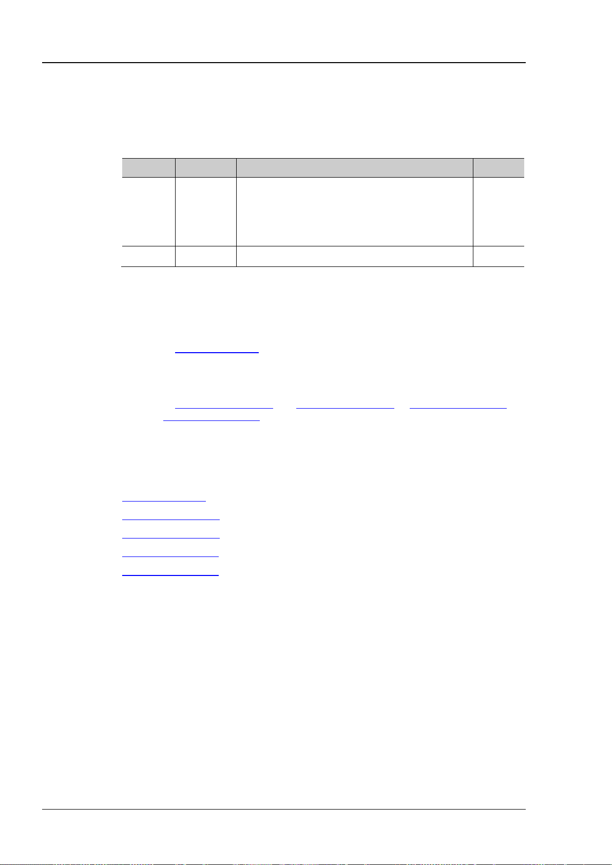
RIGOL Chapter 2 Command System
:MEASure:ITEM? <item>[,<src>[,<src>]]
Name
Type
Range
Default
RPHase|FPHase|}
and :MEASure:SETup:PSB commands by default.
Format
:MEASure:ITEM? OVERshoot,CHANnel2 /*The query returns 8.888889e-03*/
:MEASure:SETup:PSB
:MEASure:ITEM
Syntax :MEASure:ITEM <item>[,<src>[,<src>]]
Description Measure any waveform parameter of the specified source, or query the measurement
result of any waveform parameter of the specified source.
Parameter
Explanation [,<src>[,<src>]] sets the source of the parameter to be measured.
<item> Discrete {VMAX|VMIN|VPP|VTOP|VBASe|VAMP|VAVG|
-VRMS|OVERshoot|PREShoot|MARea|MPARea|
PERiod|FREQuency|RTIMe|FTIMe|PWIDth|
NWIDth|PDUTy|NDUTy|RDELay|FDELay|
<src> Discrete {CHANnel1|CHANnel2|CHANnel3|CHANnel4} --
If the parameter to be measured only needs a single source (such as VMAX, VMIN,
VPP, VTOP, VBASe, VAMP, VAVG, VRMS, OVERshoot, MARea, MPARea, PREShoot,
PERiod, FREQuency, RTIMe, FTIMe, PWIDth, NWIDth, PDUTy and NDUTy), you only
need to set one source. If [,<src>[,<src>]] is omitted, the sourc e is the one selec ted
by the
:MEASure:SOURce command by default.
Return
Example
Related
Commands
If the parameter to be measured needs two sources (such as RDELay, FDELay,
RPHase and FPHase), the command needs to include two sources; otherwise, the
command is invalid. If [,<src>[,<src>]] is omitted, the sources are the ones s elected
by the
:MEASure:SETup:DSA and :MEASure:SETup:DSB or :MEASure:SETup:PSA
The query returns the measurement result in scientific notation.
:MEASure:ITEM OVERshoot,CHANnel2 /*Enable the overshoot measurement of CH2*/
:MEASure:SOURce
:MEASure:SETup:DSA
:MEASure:SETup:DSB
:MEASure:SETup:PSA
2-62 DS1000Z Programming Guide
Page 77
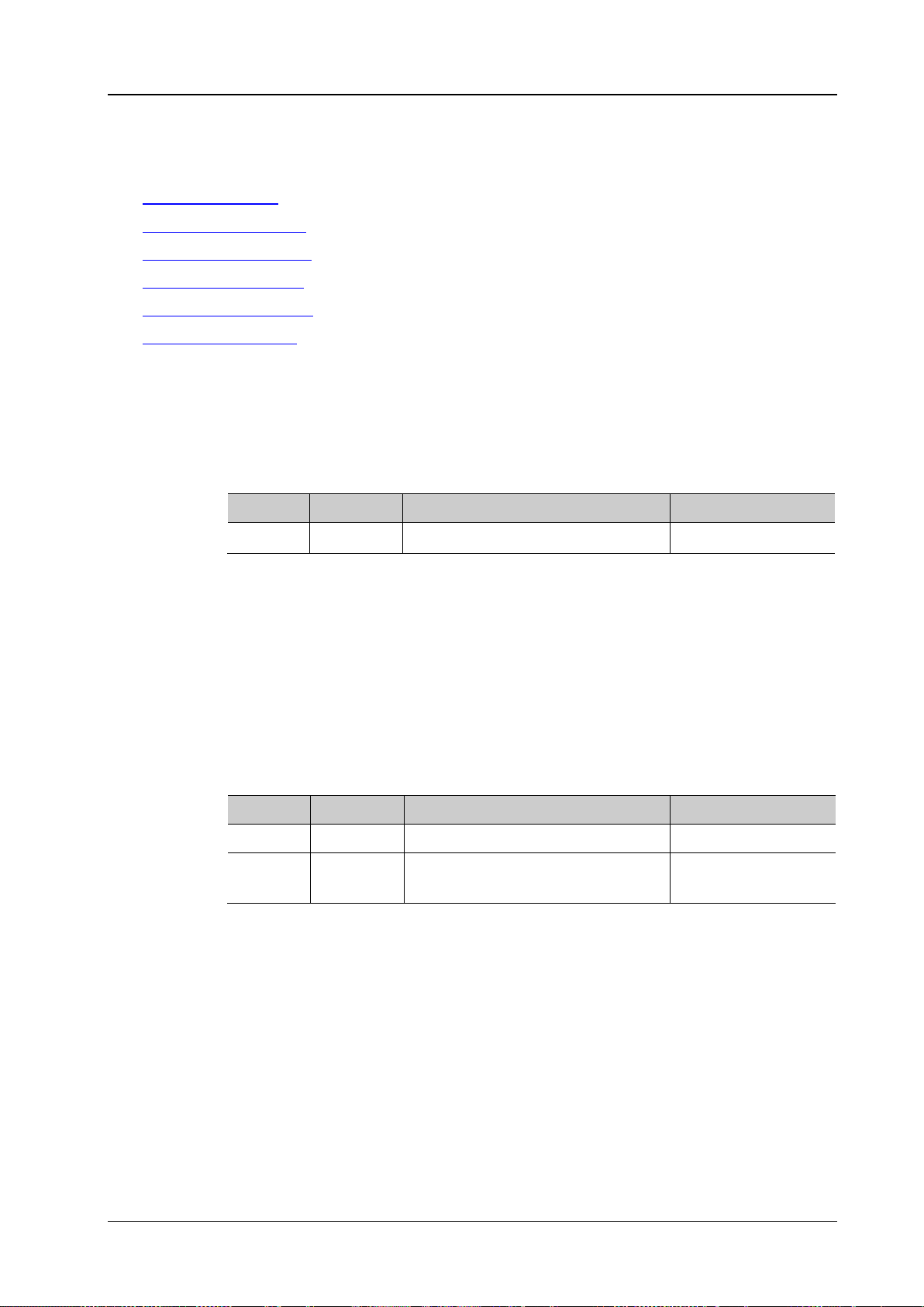
Chapter 2 Command System RIGOL
:REFerence:DISPlay?
Description
Enable or disable the REF function, or query the status of the REF function.
Name
Type
Range
Default
Format
Example
:REFerence:DISPlay ON
:REFerence<n>:ENABle?
reference channel.
Name
Type
Range
Default
<n>
Discrete
{1|2|3|4|5|6|7|8|9|10}
1
Format
Example
:REFerence1:ENABle ON
:REFerence Commands
Command List:
:REFerence:DISPlay
:REFerence<n>:ENABle
:REFerence<n>:SOURce
:REFerence<n>:VSCale
:REFerence<n>:VOFFset
:REFerence<n>:RESet
:REFerence:DISPlay
Syntax :REFerence:DISPlay <onoff>
Parameter
Return
<onoff> Bool {{0|OFF}|{1|ON}}
The query returns 0 or 1.
0|OFF
:REFerence<n>:ENABle
Syntax :REFerence<n>:ENABle <bool>
Description Enable or disable the specified reference channel, or query the status of the specified
Parameter
<bool> Bool {{0|OFF}|{1|ON}}
Return
The query returns 0 or 1.
Ref1: 1|ON
Others: 0|OFF
DS1000Z Programming Guide 2-63
Page 78
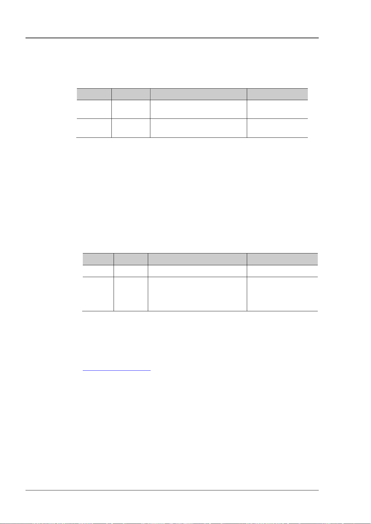
RIGOL Chapter 2 Command System
:REFerence<n>:SOURce?
Description
Set or query the source of the specified reference channel.
Name
Type
Range
Default
CHANnel3|CHANnel4|MATH}
selected as the source or the specified reference channel.
Format
:REFerence<n>:VSCale?
as the unit of the source.
Name
Type
Range
Default
waveform
this command.
Return Format
The query returns the vertical scale in scientific notation.
Example
:REFerence1:VSCale 2
Command
:REFerence<n>:SOURce
Syntax :REFerence< n>:SOURce <source>
Parameter
<n> Discrete {1|2|3|4|5|6|7|8|9|10} None
<source> Discrete
{CHANnel1|CHANnel2|
CHANnel1
Explanation Among CH1, CH2, CH3, CH4 and MATH, only the channe l currently enabled can be
Return
Example
The query returns CHAN1, CHAN2, CHAN3, CHAN4 or MATH.
:REFerence1:SOURce CHANnel1
:REFerence<n>:VSCale
Syntax :REFerence<n>:VSCale <scale>
Description Set or query the vertical scale of the specified reference channel. The unit is the same
Parameter
<n> Discrete {1|2|3|4|5|6|7|8|9|10} None
The vertical scale of
the source when saving
the reference
<scale> Real
Related to the probe ratio:
when probe ratio is 1: 1mV to 10V
Explanation This command is valid only when the specified reference channel has stored reference
waveform. Otherwise, the oscilloscope will display “No reference data!” when sending
Related
:REFerence<n>:SOURce
2-64 DS1000Z Programming Guide
Page 79
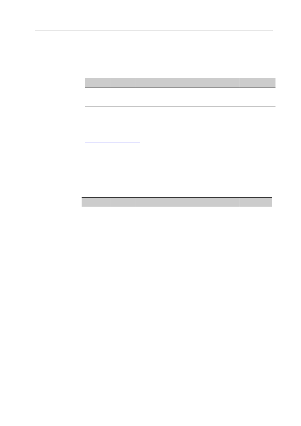
Chapter 2 Command System RIGOL
:REFerence<n>:VOFFset?
Name
Type
Range
Default
<n>
Discrete
{1|2|3|4|5|6|7|8|9|10}
None
<offset>
Real
-10*RefVerticalScale to 10*RefVerticalScale
0
Explanation
RefVerticalScale refers to the vertical scale of the reference channel.
Return Format
The query returns the vertical offset in scient ific notation.
Example
:REFerence1:VOFFset 10
Syntax
:REFerence<n>:RESet
default values.
Name
Type
Range
Default
<n>
Discrete
{1|2|3|4|5|6|7|8|9|10}
None
:REFerence<n>:VOFFset
Syntax :REFerence<n>:VOFFset <offset>
Description Set or query t he vertical offset of the specified reference channel. The unit is the
same as the unit of the source.
Parameter
Related
Commands
:REFerence<n>:SOURce
:REFerence<n>:VSCale
:REFerence<n>:RESet
Description Reset the vertical scale and vertical offset of the specified reference channel to their
Parameter
DS1000Z Programming Guide 2-65
Page 80

RIGOL Chapter 2 Command System
[:SOURce[<n>]] Commands (DS1000Z-S Only)
Command List:
[:SOURce[<n>]]:OUTPut[<n>][:STATe]
[:SOURce[<n>]]:OUTPut[<n>]:IMPedance
[:SOURce[<n>]]:FREQuency[:FIXed]
[:SOURce[<n>]]:PHASe[:ADJust]
[:SOURce[<n>]]:PHASe:INITiate
[:SOURce[<n>]]:FUNCtion[:SHAPe]
[:SOURce[<n>]]:FUNCtion:RAMP:SYMMetry
[:SOURce[<n>]]:VOLTage[:LEVel][:IMMediate][:AMPLitude]
[:SOURce[<n>]]:VOLTage[:LEVel][:IMMediate]:OFFSet
[:SOURce[<n>]]:PULSe:DCYCle
[:SOURce[<n>]]:MOD[:STATe]
[:SOURce[<n>]]:MOD:TYPe
[:SOURce[<n>]]:MOD:AM[:DEPTh]
[:SOURce[<n>]]:MOD:AM:INTernal:FREQuency
[:SOURce[<n>]]:MOD:FM:INTernal:FREQuency
[:SOURce[<n>]]:MOD:AM:INTernal:FUNCtion
[:SOURce[<n>]]:MOD:FM:INTernal:FUNCtion
[:SOURce[<n>]]:MOD:FM[:DEVIation]
[:SOURce[<n>]]:APPLy?
[:SOURce[<n>]]:APPLy:NOISe
[:SOURce[<n>]]:APPLy:PULSe
[:SOURce[<n>]]:APPLy:RAMP
[:SOURce[<n>]]:APPLy:SINusoid
[:SOURce[<n>]]:APPLy:SQUare
[:SOURce[<n>]]:APPLy:USER
2-66 DS1000Z Programming Guide
Page 81
Chapter 2 Command System RIGOL
[:SOURce[<n>]]:OUTPut[<n>][:STATe]?
Name
Type
Range
Default
default
<bool>
Bool
{{0|OFF}|{1|ON}}
0|OFF
[:SOURce[<n>]]. If both are omitted, the operation is performed on source 1 by default.
Format
Example
:OUTPut 1
Description
Set or query the impedance of the specified source channel.
Name
Type
Range
Default
default
<impedance>
Discrete
{OMEG|FIFTy}
OMEG
source 1 by default .
Format
[:SOURce[<n>]]:OUTPut[<n>][:STATe]
Syntax [:SOURce[<n>]]:OUTPut[<n>][:STATe] <bool>
Description T urn on or off the output of the specified source channel, or query the status of the output
of the specified source channel.
Parameter
If omitted, the operation is
[<n>] Discrete {1|2}
Explanation [:SOURce[<n>]] and [<n>] are used to specify the source channel. The former enjoys
higher priority over the latter, namely if [:SOURce[<n>]] is omitted, the channel is
specified by [<n>] and if [:SOURce[<n>]] is not omitted, the channel is specified by
performed on source 1 by
Return
The query returns OFF or ON.
[:SOURce[<n>]]:OUTPut[<n>]:IMPedance
Syntax [:SOURce[<n>]]:OUTPut[<n>]:IMPedance <impedance>
[:SOURce[<n>]]:OUTPut[<n>]:IMPedance?
Parameter
[<n>] Discrete {1|2}
Explanation OMEG: high impedance; FIFTy: 50Ω
[:SOURce[<n>]] and [<n>] are used to specify the source channel. The former
enjoys higher priority over the latter, namely if [:SOURce[<n>]] is omitted, the
channel is specified by [<n>] and if [:SOURce[<n>]] is not omitted, the channel is
specified by [:SOURce[<n>]]. If both are omitted, the operation is performed on
If omitted, the operation is
performed on source 1 by
Return
The query returns OMEG or FIFT.
Example :OUTPut:IMPedance FIFTy
DS1000Z Programming Guide 2-67
Page 82
RIGOL Chapter 2 Command System
[:SOURce[<n>]]:FREQuency[:FIXed]?
Name
Type
Range
Default
default
Format
Example
:FREQuency 1000
[:SOURce[<n>]]:MOD:TYPe
[:SOURce[<n>]]:PHASe[:ADJust]?
(°).
Name
Type
Range
Default
<phase>
Real
0 to 360
0
Format
Example
:PHASe 90
[:SOURce[<n>]]:FREQuency[:FIXed]
Syntax [:SOURce[<n>]]:FREQuency[:FIXed] <frequency>
Description Set or query the output frequency of the specified source channel if the modulation is not
enabled or the carrier frequency if the modulation is enabled. The default unit is Hz.
Parameter
If omitted, the operation is
[<n>] Discrete {1|2}
Sine: 0.1Hz to 25MHz
Square: 0.1Hz to 15MHz
<frequency> Real
Pulse: 0.1Hz to 1MHz
Ramp: 0.1Hz to 100kHz
Arbitrary waveform: 0.1Hz to
10MHz
performed on source 1 by
100kHz
Return
Related
The query returns the frequency in scientific notation, such as 2.0000000e+05.
[:SOURce[<n>]]:MOD[:STATe]
Commands
[:SOURce[<n>]]:PHASe[:ADJust]
Syntax [:SOURce[<n>]]:PHASe[:ADJust] <phase>
Description Set or query the start phase of the specified source cha nnel. The default unit is degree
Parameter
If omitted, the operation is
Return
[<n>] Discrete {1|2}
The query returns the start phase in scientific notation, such as 0.0000000e+00.
performed on source 1 by
default
2-68 DS1000Z Programming Guide
Page 83
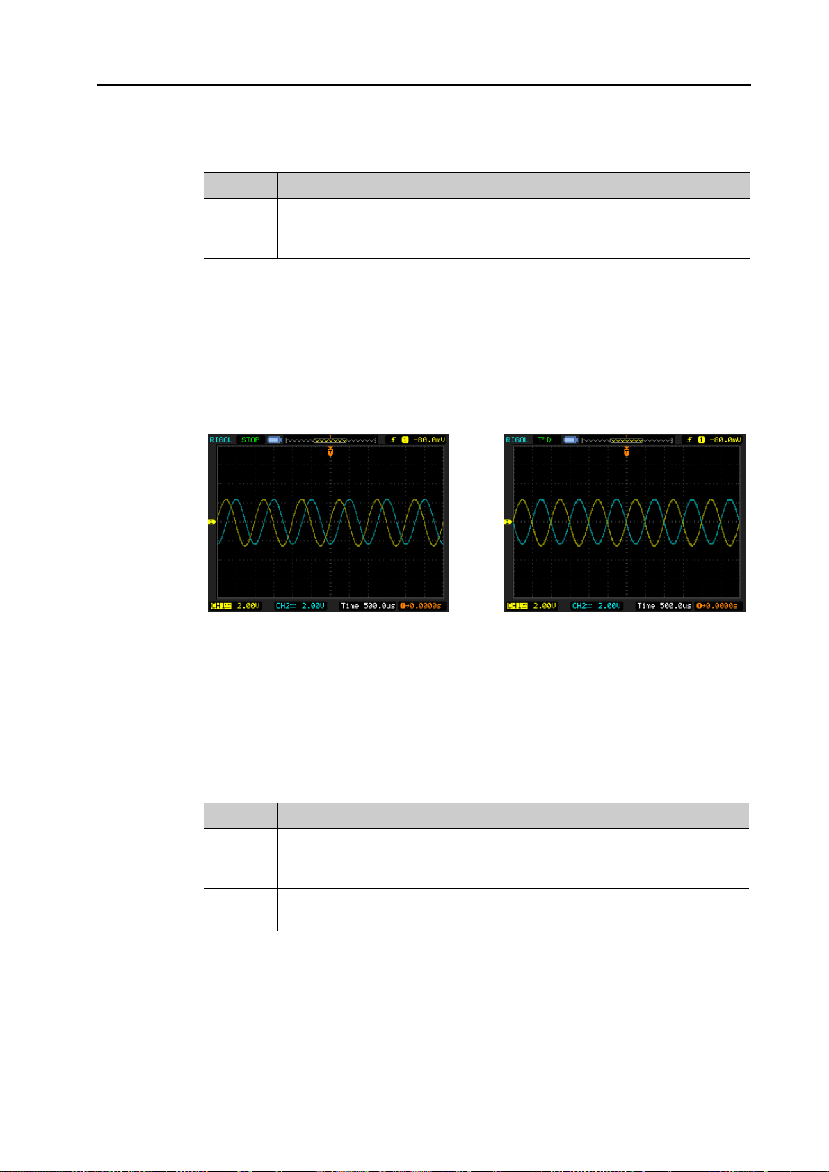
Chapter 2 Command System RIGOL
Syntax
[:SOURce[<n>]]:PHASe:INITiate
Description
Execute the align phase operation.
Name
Type
Range
Default
default
Before Aligning Phase After Aligning Phase
[:SOURce[<n>]]:FUNCtion[:SHAPe]?
Name
Type
Range
Default
default
|NOISe|DC|INTErnal|EXTernal}
EXTernal: arbitrary waveform
Format
Example
:FUNCtion SQUare
[:SOURce[<n>]]:PHASe:INITiate
Parameter
If omitted, the operation is
[<n>] Discrete {1|2}
Explanation When the align phase operation is performed, the instrument re-configures the two
channels to make them output with the specified frequency and phase.
For two signals whose frequencies are the same or in multiple, this operation will align
their phases. For example, assume Source1 output a 1kHz, 5Vpp, 0° sine waveform and
Source2 outputs a 1kHz, 5Vpp, 180° sine waveform. Sample the two waveforms using
another oscilloscope and display them stably; you will see that the waveforms shown on
the oscilloscope do not always have a p hase deviation of 180°. At this point, execute the
align phase operation and the waveforms shown on the oscilloscope will have a phase
deviation of 180° without any manual adjustment of the start phase of the generator.
performed on source 1 by
[:SOURce[<n>]]:FUNCtion[:SHAPe]
Syntax [:SOURce[<n>]]:FUNCtion[ :SHAPe] <wave>
Description Select or query the output waveform when the modulation of the specified source channel
is not enabled. Select or query the carrier waveform when the mod ulation is enabled. At
this point, if PULSe, NOISe or DC is selected, the modulation will turn off automatically.
Parameter
If omitted, the operation is
[<n>] Discrete {1|2}
<wave> Discrete
{SINusoid|SQUare|RAMP|PULSe
Explanation INTErnal: built-in waveforms (7 built-in waveforms are provided by DS1000Z,
including Sinc, Exp.Rise, Exp.Fall, ECG, Gauss, Lorentz and Haversine)
performed on source 1 by
SINusoid
Return
DS1000Z Programming Guide 2-69
The query returns SIN, SQU, RAMP, PULS, NOIS, DC, INTE or EXT.
Page 84
RIGOL Chapter 2 Command System
[:SOURce[<n>]]:FUNCtion:RAMP:SYMMetry?
Name
Type
Range
Default
default
Format
Example
:FUNCtion:RAMP:SYMMetry 50
Command
[:SOURce[<n>]]:VOLTage[:LEVel][:IMMediate][:AMPLitude]?
Description
Set or query the output amplitude of the specified source channel. The default unit is Vpp.
Name
Type
Range
Default
default
50Ω: 10mVpp to 2.5Vpp
impedance.
Format
[:SOURce[<n>]]:FUNCtion:RAMP:SYMMetry
Syntax [:SOURce[<n>]]:FUNCtion:RAMP:SYMMetry <val>
Description Set or query the ramp symmetry (the percentage that the rising period takes up in the
whole period) of the specified source channel . The default unit is %.
Parameter
If omitted, the operation is
[<n>] Discrete {1|2}
<val> Real 0 to 100 10
performed on source 1 by
Return
Related
The query returns the symmetry in scientific notation, such as 5.000000e+01.
[:SOURce[<n>]]:FUNCtion[:SHAPe]
[:SOURce[<n>]]:VOLTage[:LEVel][:IMMediate][:AMPLitude]
Syntax [:SOURce[<n>]]:VOLTage[:LEVel][:IMMediate][:AMPLitude] <Amplitude>
Parameter
If omitted, the operation is
[<n>] Discrete {1|2}
Related to the output
<Ampliude> Real
impedance:
HighZ: 20mVpp to 5Vpp
performed on source 1 by
1Vpp
Explanation You can use the [:SOURce[<n>]]:OUTPut[<n>]:IMPedance command to set the output
Return
The query returns the amplitude in scientific notation, s uch as 1.0000000e+00.
Example :VOLTage 2
2-70 DS1000Z Programming Guide
Page 85
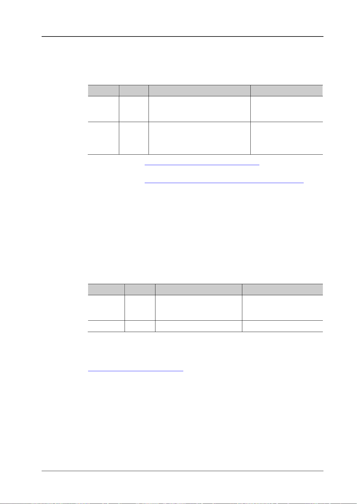
Chapter 2 Command System RIGOL
[:SOURce[<n>]]:VOLTage[:LEVel] [:IMMediate]:OFFSet?
Description
Set or query the DC offset of the specified source channel. The default unit is V.
Name
Type
Range
Default
by default
command to set the output amplitude.
Format
[:SOURce[<n>]]:PULSe:DCYCle?
period) of the specified source channel. The default unit is %.
Name
Type
Range
Default
default
<percent>
Real
10 to 90
20
Format
Example
:PULSe:DCYCle 50
[:SOURce[<n>]]:VOLTage[:LEVel][:IMMediate]:OFFSet
Syntax [:SOURce[<n>]]:VOLTage[:LEVel] [:IMMediate]:OFFSet <offset>
Parameter
If omitted, the operation
[<n>] Discrete {1|2}
Related to the output impeda nce
<offset> Real
and amplitude:
HighZ: ±(2.5V-current amplitude/2)
50Ω: ±(1.25V-current amplitude/2)
Explanation You can use the [:SOURce[<n>]]:OUTPut[<n>]:IMPedance command to set the
output impedance.
is performed on source 1
0V
Return
Example
You can use the
The query returns the DC offset in scientific notation, such as 1.0000000e+00.
:VOLTage:OFFSet 0.5
[:SOURce[<n>]]:VOLTage[:LEVel][:IMMediate][:AMPLitude]
[:SOURce[<n>]]:PULSe:DCYCle
Syntax [:SOURce[<n>]]:PULSe:DCYCle <percent>
Description Set or query the pulse duty cycle (the percentage that the high level takes up in the whole
Parameter
If omitted, the operation is
Return
[<n>] Discrete {1|2}
The query returns the duty cycle in scientific notation, such as 5.000000e+01.
performed on source 1 by
Related
[:SOURce[<n>]]:FUNCtion[:SHAPe]
Command
DS1000Z Programming Guide 2-71
Page 86
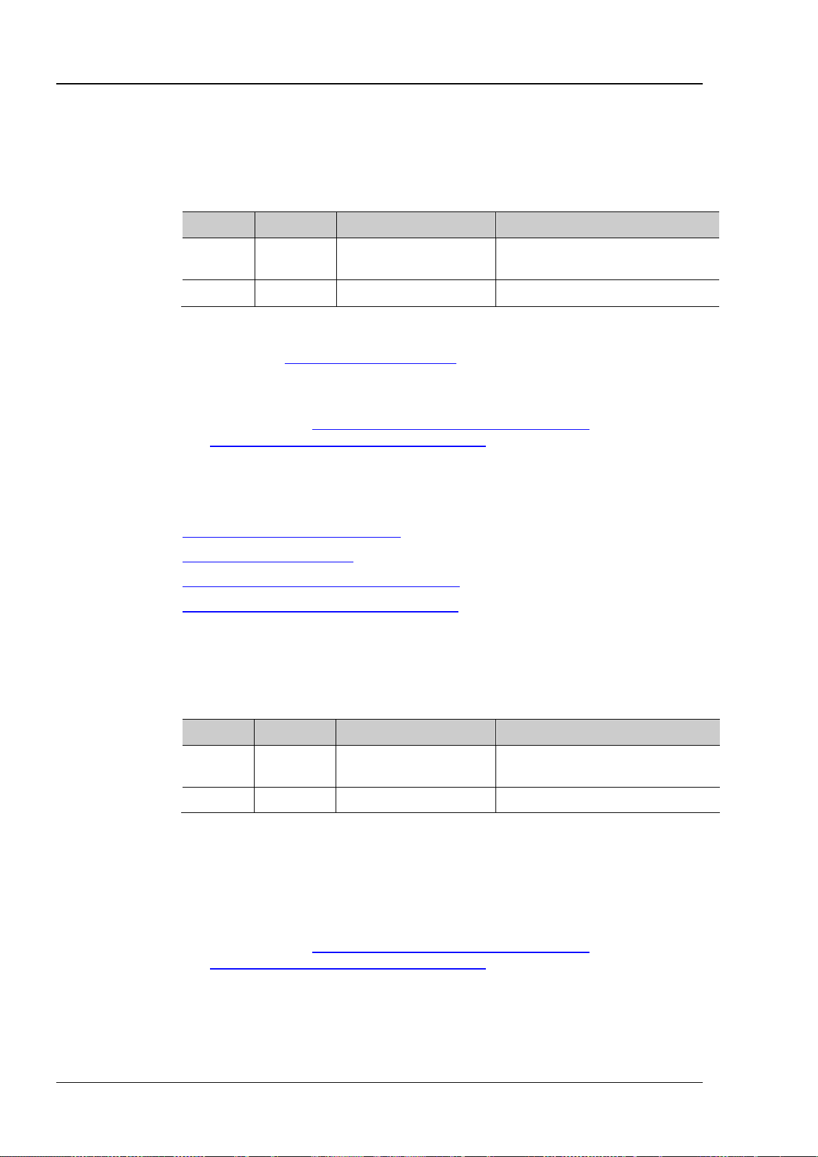
RIGOL Chapter 2 Command System
[:SOURce[<n>]]:MOD[:STATe]?
Name
Type
Range
Default
performed on source 1 by default
<bool>
Bool
{{1|ON}|{0|OFF}}
0|OFF
Ramp or Noise as the modulating waveform.
Return Format
The query returns OFF or ON.
Example
:MOD ON
[:SOURce[<n>]]:MOD:TYPe?
Description
Set or query the modulation type of the specified source channel.
Name
Type
Range
Default
performed on source 1 by default
<type>
Discrete
{AM|FM}
AM
Ramp or Noise as the modulating waveform.
Return Format
The query returns AM or FM.
Example
:MOD:TYPe AM
[:SOURce[<n>]]:MOD[:STATe]
Syntax [:SOURce[<n>]]:MOD[:STATe] <bool>
Description Enable or disable the modulation of the specified source channel, or query the status
of the modulation o f the specified source channel.
Parameter
[<n>] Discrete {1|2}
If omitted, the operation is
Explanation The signal source of DS1000Z provides two types of modulations (Amplitude
Modulation (AM) and Frequency Modulati o n (FM )) which can be selected by
sending the
[:SOURce[<n>]]:MOD:TYPe command.
Sine, Square, Ramp, Built-in waveforms or Arb wavef orm (except DC) can be used
as the carrier waveform.
You can use the
[:SOURce[<n>]]:MOD:AM:INTernal:FUNCtion or
[:SOURce[<n>]]:MOD:FM:INTernal:FUNCtion command to selelct Sine, Square,
Related
Commands
[:SOURce[<n>]]:FUNCtion[:SHAPe]
[:SOURce[<n>]]:MOD:TYPe
[:SOURce[<n>]]:MOD:AM:INTernal:FUNCtion
[:SOURce[<n>]]:MOD:FM:INTernal:FUNCtion
[:SOURce[<n>]]:MOD:TYPe
Syntax [:SOURce[<n>]]:MOD:TYPe <type>
Parameter
[<n>] Discrete {1|2}
If omitted, the operation is
Explanation AM: amplitude modulation. The ampl itude of the carrier w avef orm v aries with the
amplitude of the modulating waveform.
FM: frequency modulati on. The frequency of the carrier waveform varies with the
amplitude of the modulating waveform.
Sine, Square, Ramp, Built-in waveforms or Arb wavef orm (except DC) can be used
as the carrier waveform.
You can use the
[:SOURce[<n>]]:MOD:AM:INTernal:FUNCtion or
[:SOURce[<n>]]:MOD:FM:INTernal:FUNCtion command to selelct Sine, Square,
2-72 DS1000Z Programming Guide
Page 87
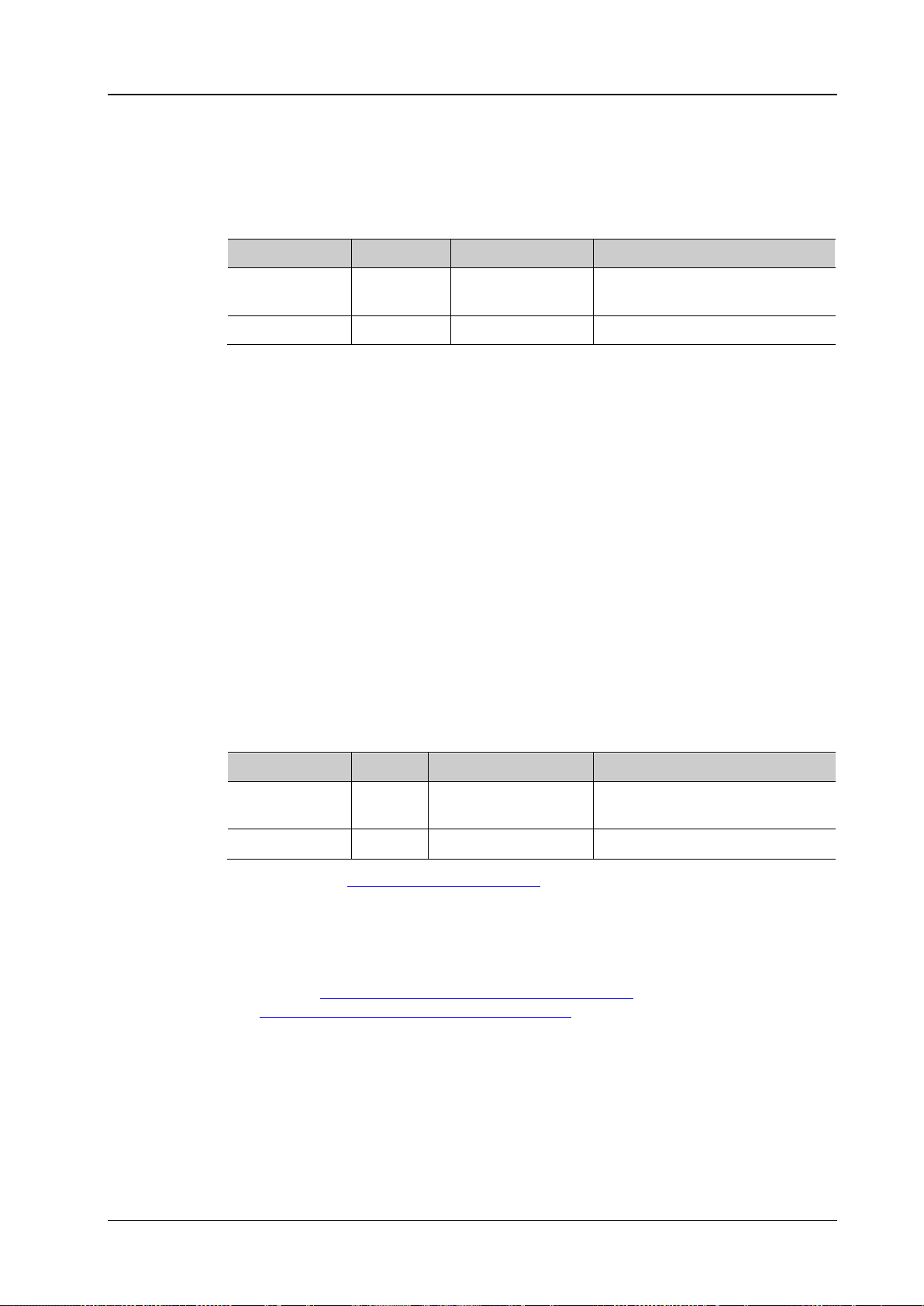
Chapter 2 Command System RIGOL
[:SOURce[<n>]]:MOD:AM[:DEPTh]?
Name
Type
Range
Default
performed on source 1 by default
<depth>
Real
0 to 120
100
occur and the output amplitude of t he instrument would not exceed 5Vpp (50Ω load).
Format
Example
:MOD:AM 80
[:SOURce[<n>]]:MOD:FM:INTernal:FREQuency?
channel. The default unit is Hz.
Name
Type
Range
Default
performed on source 1 by default
Noise as the modulating waveform.
Format
Example
:MOD:AM:INTernal:FREQuency 100
[:SOURce[<n>]]:MOD:AM[:DEPTh]
Syntax [:SOURce[<n>]]:MOD:AM[:DEPTh] <depth>
Description Set or query the AM modulation depth (indicates the amplitude variation degree and is
expressed as a percentage) of the specified source channel. The default unit is %.
Parameter
[<n>] Discrete {1|2}
If omitted, the operation is
Explanation In 0% modul ation, the output amplitude is half of the carrier w a veform amplitude.
In 100% modulation, the output amplitude is equal to the carrier waveform amplitude.
In >100% modulation, envelop distortion which should be avoided in the real circuit will
Return
The query returns an integer.
[:SOURce[<n>]]:MOD:AM:INTernal:FREQuency
[:SOURce[<n>]]:MOD:FM:INTernal:FREQuency
Syntax [:SOURce[<n>]]:MOD:AM:IN Ternal:FREQuency <freque nc y>
[:SOURce[<n>]]:MOD:AM:INTernal:FREQuency?
[:SOURce[<n>]]:MOD:FM:INTernal:FREQue n cy <freq ue ncy>
Description Set or query the modulating waveform freq uency of AM or FM of the specified source
Parameter
[<n>] Discrete {1|2}
If omitted, the operation is
<frequency> Real 1Hz to 50kHz 1kHz
Explanation Sending the [:SOURce[<n>]]:MOD:TYPe command can set the modulation type.
AM: amplitude modulation. The amplitude of the carrier waveform varies with the
amplitude of the modulating waveform.
FM: frequency modu lation. The frequency of the carrier waveform varies with the
amplitude of the modulating waveform.
Sending
[:SOURce[<n>]]:MOD:AM:INTernal:FUNCtion or
[:SOURce[<n>]]:MOD:FM:INTernal:FUNCtion can selelct Sine, Square, Ramp or
Return
The query returns an integer.
DS1000Z Programming Guide 2-73
Page 88
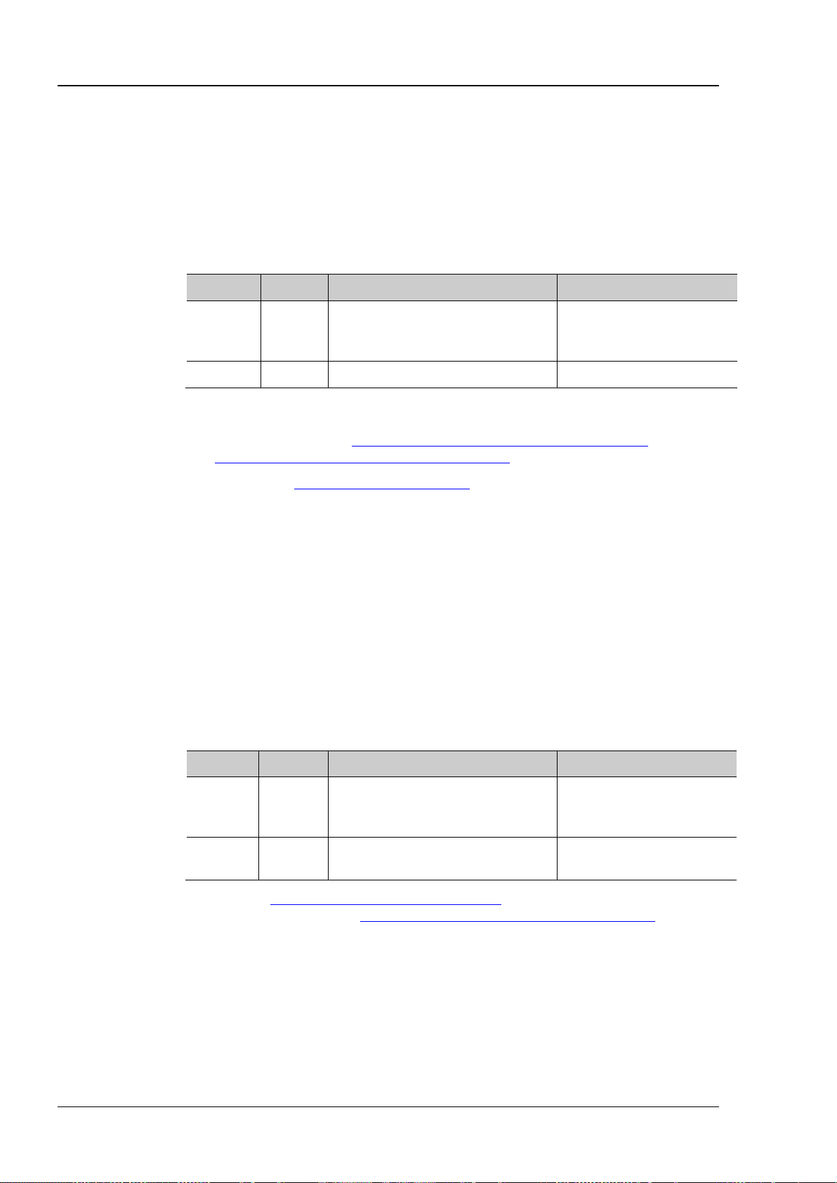
RIGOL Chapter 2 Command System
[:SOURce[<n>]]:MOD:FM:INTernal:FUNCtion?
Description
Set or query the modulating waveform of AM or FM of the specified source channel.
default
amplitude of the modulating waveform.
Return Format
The query returns SIN, SQU, RAMP or NOIS.
Example
:MOD:AM:INTernal:FUNCtion SQUare
[:SOURce[<n>]]:MOD:FM[:DEVIation]?
is Hz.
Name
Type
Range
Default
default
frequency
decreases by the “frequency deviation”.
Return Format
The query returns an integer.
Example
:MOD:FM 100
[:SOURce[<n>]]:MOD:AM:INTernal:FUNCtion
[:SOURce[<n>]]:MOD:FM:INTernal:FUNCtion
Syntax [:SOURce[<n>]]:MOD:AM:IN Ternal:FUNCtion <wave>
[:SOURce[<n>]]:MOD:AM:INTernal:FUNCtion?
[:SOURce[<n>]]:MOD:FM:INTernal:FUNCtion <wave>
Parameter
Name Type Range Default
If omitted, the operation is
[<n>] Discrete {1|2}
performed on source 1 by
<wave> Discrete {SINusoid|SQUare|RAMP|NOISe} SINusoid
Explanation Sine (SINusoid), Square (SQUare), Ramp (RAMP) or Noise (NOISe) can be selected
as the modulating waveform. You can set the frequency of the modulating
waveform by sending
[:SOURce[<n>]]:MOD:AM:INTernal:FREQuency or
[:SOURce[<n>]]:MOD:FM:INTernal:FREQuency.
Sending the
[:SOURce[<n>]]:MOD:TYPe command can set the modulation type.
AM: amplitude modulation. The amplitude of the carrier waveform varies with the
amplitude of the modulating waveform.
FM: frequency modulation. The frequency of the carrier waveform varies with the
[:SOURce[<n>]]:MOD:FM[:DEVIation]
Syntax [:SOURce[<n>]]:MOD:FM[:DEVIati on] <de v>
Description Set or query the FM frequency deviation of the specified source channel. The default unit
Parameter
If omitted, the operation is
[<n>] Discrete {1|2}
<dev> Real
0Hz to the carrier waveform
performed on source 1 by
10kHz
Explanation Sending [:SOURce[<n>]]:FREQuency[:FIXed] can set the carrier waveform
frequency and sending
[:SOURce[<n>]]:MOD:FM:INTernal:FREQuency can set the
FM modulation frequency.
When the modulating waveform ampl itude reaches its maximum, the carrier
waveform frequency increases by the “frequency deviation”. When the modulating
waveform amplitude reaches its minimum, the carrier waveform frequency
2-74 DS1000Z Programming Guide
Page 89
Chapter 2 Command System RIGOL
Syntax
[:SOURce[<n>]]:APPLy?
Description
Query the output configurations of the specified source channel.
Name
Type
Range
Default
source 1 by default
corresponding parameter does not exist, it will be replaced by "DEF".
Example
:APPLy? /*The query returns SIN,1000.000000,1.000000,0.000000,0.000000*/
[:SOURce[<n>]]:APPLy:USER [<freq>[,<amp>[,<offset>[,<phase>]]]]
and parameters.
Name
Type
Range
Default
1 by default
Arbitrary waveform: 0.1Hz to 10MHz
50Ω: ±(1.25V-current amplitude/2)
0°
[:SOURce[<n>]]:APPLy?
Parameter
[<n>] Discrete {1|2}
Return
Format
The query returns the output configurations i n “<waveform
name>,<frequency>,<amplitude>,<offset>,<start phase>” format. If the
[:SOURce[<n>]]:APPLy:NOISe
[:SOURce[<n>]]:APPLy:PULSe
[:SOURce[<n>]]:APPLy:RAMP
[:SOURce[<n>]]:APPLy:SINusoid
[:SOURce[<n>]]:APPLy:SQUare
[:SOURce[<n>]]:APPLy:USER
Syntax [:SOURce[<n>]]:APPLy:NOISe [<amp>[,<offset>]]
[:SOURce[<n>]]:APPLy:PULSe [<freq>[,<amp>[,<offset>[,<phase>]]]]
[:SOURce[<n>]]:APPLy:RAMP [<freq>[,<amp>[,<offset>[,<phase>]]]]
[:SOURce[<n>]]:APPLy:SINusoid [<freq>[,<amp>[,<offset>[,<phase>]]]]
[:SOURce[<n>]]:APPLy:SQUare [<freq>[,<amp>[,<offset>[,<phase>]]]]
If omitted, the operation is performed on
Description Configure the specified source channel to output the signal with the specified waveform
Parameter
If omitted, the
[<n>] Discrete {1|2}
Sine: 0.1Hz to 25MHz
Square: 0.1Hz to 15MHz
<freq> Real
<amp> Real
<offset> Real
<phase> Real 0° to 360°
Pulse: 0.1Hz to 1MHz
Ramp: 0.1Hz to 100kHz
Related to the output impedance:
HighZ: 20mVpp to 5Vpp
50Ω: 10mVpp to 2.5Vpp
Related to the out put impedance and
amplitude:
HighZ: ±(2.5V-current amplitude/2)
operation is
performed on source
100kHz
1Vpp
0mV
DS1000Z Programming Guide 2-75
Page 90

RIGOL Chapter 2 Command System
Explanation These commands are used to select the waveform shape.
NOISe: select Noise
PULSe: select Pulse
RAMP: select Ramp
SINusoid: select Sine
SQUare: select Squa re
USER: select Arbitrary waveform
<freq>: set the frequency of the specified waveform (Noise does not have this
parameter). The default unit is Hz
<amp>: set the amplitude of the specified waveform. The default unit is Vpp
<offset>: set the DC offset of the specified waveform. The default unit is V
<phase>: set the start phase of the specified waveform (Noise does not have this
parameter). The default unit is degree (°).
Users can omit one or multiple parameters. When all of the par ameters ar e omi t ted,
the commands only select the waveform shape but do not modify the parameters.
The four parameters (<freq>, <amp>, <offset> and <phase>) are in order . Y ou can
not omit one parameter and set the one/ones behind i t. For example, you can not
omit <freq> and set <amp> directly.
2-76 DS1000Z Programming Guide
Page 91
Chapter 2 Command System RIGOL
:SYSTem:AUToscale?
Name
Type
Range
Default
<bool>
Bool
{{0|OFF}|{1|ON}}
1|ON
command will be invalid.
Format
Example
:SYSTem:AUToscale ON
:SYSTem:BEEPer?
Description
Enable or disable the beeper, or query the status of the beeper.
Name
Type
Range
Default
<bool>
Bool
{{0|OFF}|{1|ON}}
0|OFF
Format
Example
:SYSTem:BEEPer ON
:SYSTem Commands
The :SYSTem commands are used to set the system-related parameters, such as the sound and language.
Command List:
:SYSTem:AUToscale
:SYSTem:BEEPer
:SYSTem:ERRor[:NEXT]?
:SYSTem:GPIB
:SYSTem:LANGuage
:SYSTem:LOCKed
:SYSTem:PON
:SYSTem:OPTion:INSTall
:SYSTem:OPTion:UNINSTall
:SYSTem:AUToscale
Syntax :SYSTem:AUToscale <bool>
Description
Enable or disable the AUTO key at the front panel, or query the status of the AUTO key.
Parameter
Explanation
Users can disable the AUTO key by sending this command or pressing Utility
Auto Options Lock and enable it by sending this command.
After the AUTO key is disabled, the Auto Scale operation is invalid. The :AUToscale
Return
The query returns 0 or 1.
:SYSTem:BEEPer
Syntax :SYSTem:BEEPer <bool>
Parameter
Return
The query returns 0 or 1.
DS1000Z Programming Guide 2-77
Page 92

RIGOL Chapter 2 Command System
Syntax
:SYSTem:ERRor[:NEXT]?
Description
Query and delete the last system error message.
string. For example, -113,"Undefined header; command cannot be found".
:SYSTem:GPIB?
Description
Set or query the GPIB address.
Name
Type
Range
Default
<adr>
Integer
1 to 30
2
Explanation
The GPIB address is not affected by sending *RST.
Format
Example
:SYSTem:GPIB 7
:SYSTem:LANGuage?
Description
Set or query the system language.
Name
Type
Range
Default
<lang>
Discrete
{SCHinese|ENGLish}
SCHinese
Explanation
The system language is not affected by sending *RST.
Format
Example
:SYSTem:LAN Guag e SC Hin es e
:SYSTem:LOCKed?
function.
Name
Type
Range
Default
<bool>
Bool
{{0|OFF}|{1|ON}}
0|OFF
Format
:SYSTem:ERRor[:NEXT]?
Return
Format
The query returns the error message in “<message number>,<message content>”
format. Wherein, <message number> is an int eger and <message content> is a ASCII
:SYSTem:GPIB
Syntax :SYSTem:GPIB <adr>
Parameter
Return
The query returns an integer.
:SYSTem:LANGuage
Syntax :SYSTem:LAN Guag e <la ng >
Parameter
Return
The query returns SCH or ENGL.
:SYSTem:LOCKed
Syntax :SYSTem:LOCKed <bool>
Description Enable or disable the keyboard lock function, or query the status of the keyboard lock
Parameter
Return
The query returns 0 or 1.
2-78 DS1000Z Programming Guide
Page 93
Chapter 2 Command System RIGOL
:SYSTem:PON?
Name
Type
Range
Default
<pon>
Discrete
{LATest|DEFault}
LATest
Format
Example
:SYSTem:PON LATest
Syntax
:SYSTem:OPTion:INSTall <license>
Description
Install the option.
Name
Type
Range
Default
No spaces between characters.
Example
:SYSTem:OPTion:INSTall PDUY9N9QTS9PQSWPLAETRD3UJHYA
Syntax
:SYSTem:OPTion:UNINSTall
Description
Uninstall the options installed.
:SYSTem:PON
Syntax :SYSTem :PON <pon>
Description Set or query the system configuration to be recalled when t he oscilloscop e is powered on
again after power-off.
Parameter
Return
The query returns LAT or DEF.
:SYSTem:OPTion:INSTall
Parameter
<license> ASCII String
:SYSTem:OPTion:UNINSTall
Option serial number supplied by RIGOL
None
DS1000Z Programming Guide 2-79
Page 94

RIGOL Chapter 2 Command System
:TIMebase:DELay:ENABle?
Description
Enable or disable the delayed sweep, or query the status of the delayed sweep.
Name
Type
Range
Default
<bool>
Bool
{{0|OFF}|{1|ON}}
0|OFF
waveform details.
Return Format
The query returns 0 or 1.
Example
:TIMebase:DELay:ENABle ON
:TIMebase:DELay:OFFSet?
Description
Set or query the delayed timebase offset. The default unit is s.
Name
Type
Range
Default
DelayRange = 12×DelayScale
Return Format
The query returns the offset in scientific notation.
:TIMebase:DELay:OFFSet? /*The query returns 2.0000000e-06*/
:TIMebase[:MAIN]:SCALe
:TIMebase Commands
The :TIMebase commands are used to set the horizontal parameters, such as enabling the delayed sweep
and setting the horizontal timebase mode.
Command List:
:TIMebase:DELay:ENABle
:TIMebase:DELay:OFFSet
:TIMebase:DELay:SCALe
:TIMebase[:MAIN]:OFFSet
:TIMebase[:MAIN]:SCALe
:TIMebase:MODE
:TIMebase:DELay:ENABle
Syntax :TIMebase :DE La y:E NA B le <b ool >
Parameter
Explanation Delayed sweep can be used to enlarge a length of waveform horizontally to view the
:TIMebase:DELay:OFFSet
Syntax :TIMebase:DELay:OFFSe t <of fse t >
Parameter
<offset> Real -(LeftTime - DelayRange/2) to
(RightTime - DelayRange/2)
Explanation LeftTime = 6×MainScale – MainOffset
RightTime = 6×MainScale + MainOffset
0
Example :TIMebase:DELay:OFFSet 0.000002 /*Set the delayed timebase offset to 2μs*/
Related
Commands
:TIMebase:DELay:SCALe
:TIMebase[:MAIN]:OFFSet
2-80 DS1000Z Programming Guide
Page 95
Chapter 2 Command System RIGOL
:TIMebase:DELay:SCALe?
Description
Set or query the delayed timebase scale. The default unit is s/div.
Name
Type
Range
Default
minimum is calculated using the inequality: ≥ 14 / (500MSa/s * 7) = 40ns. Taking
delayed timebase scale to 5μs.
Return Format
The query returns the scale in scientific notation.
:TIMebase:DELay:SCALe? /*The query returns 5.0000000e-08*/
Command
:TIMebase[:MAIN]:OFFSet?
Description
Set or query the main timebase offset. The default unit is s.
Name
Type
Range
Default
<offset>
Real
-Screen/2 to 1s or -Screen/2 to 5000s
0
oscilloscope in the Stoping state.
Return Format
The query returns the offset in scientific notation.
Example
:TIMebase:MAIN:OFFSe t 0. 0002 /*Set the main timebase offset to 20ms*/
:STOP
:TIMebase:DELay:SCALe
Syntax :TIMebase:DELay:SCALe < sca le _value>
Parameter
<scale_value> Real See Explanation 500ns
Explanation The maximum of <scale_value> is the main timebase scale currently set and the
minimum is related to the current sample rate ( satisfying the inequality: current
sample rate * delayed timebase scale * 7 ≥ 14) and is no less than 1ns.
The delayed timebase scale can only be the maximum or the value decreased
from the maximum in 1-2-5 step. If the minimum calculated by the inequality
mentioned above is not a settable value, the larger settable value that is nearest
to the calculated value will be used as the minimum. If the value set is between
two settable values, the smaller one will be used as the delayed timebase scale
automatically.
For example, when the main timebase scale currently set is 10.00μs and the
sample rate is 500MSa/s, the maximum of <scale_value> is 10.00μs. The
the larger settable value that is nearest to the calculated value, the minimum is
50ns. At this point, if 0.000009 (namely 9μs) is set, the instrument sets the
Example :TIMebase:DELay:SCALe 0.00000005 /*Set the delayed timebase scale to 50ns*/
Related
:TIMebase[:MAIN]:SCALe
:TIMebase[:MAIN]:OFFSet
Syntax :TIMebase[:MAIN]:OFFSet <offset >
Parameter
Explanation This command is invalid when the horizontal timebase mode is Roll and the
oscilloscope is in the Run state.
When the horizontal timebase mode is YT and the horizontal timebase is 20ms
or larger (namely the “Slow Sweep” mode), this command is invalid when the
Related
Commands
:TIMebase:MODE
:TIMebase[:MAIN]:SCALe
:RUN
DS1000Z Programming Guide 2-81
Page 96
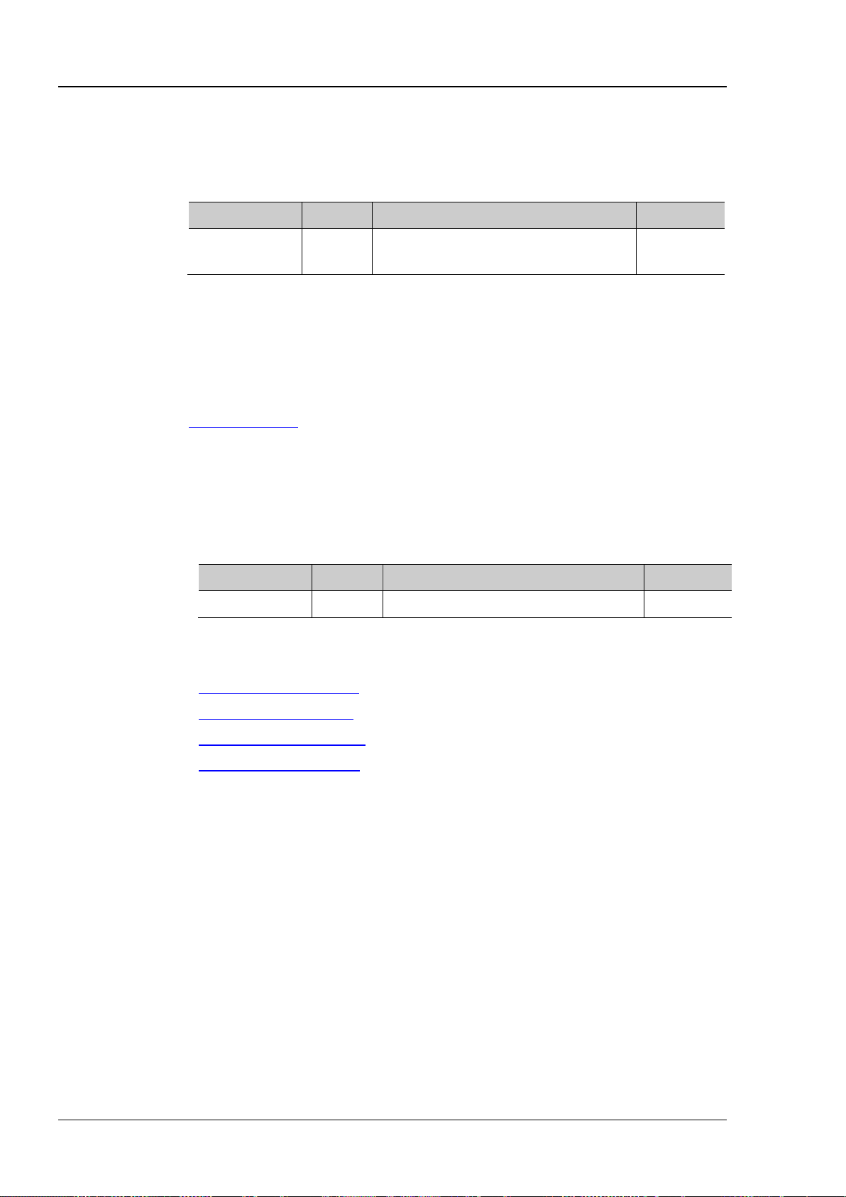
RIGOL Chapter 2 Command System
:TIMebase[:MAIN]:SCALe?
Description
Set or query the main timebase scale. The default unit is s/div.
Name
Type
Range
Default
oscilloscope in the Stoping state.
Return Format
The query returns the main timebase scale in scientific notation.
:TIMebase:MAIN:SCALe? /*The query returns 2.0000000e-04*/
Description
Set or query the mode of the horizont al timebase.
Name
Type
Range
Default
<mode>
Discrete
{MAIN|XY|ROLL}
MAIN
Example
:TIMebase:MODE XY
:TIMebase[:MAIN]:SCALe
Syntax :TIMebase[ :M AIN]:SCALe <scale_ va lue>
Parameter
<scale_value> Real Normal: 5ns to 50s in 1-2-5 step
Roll: 200ms to 50s in 1-2-5 step
Explanation When the horizontal timebase mode is YT and the horizontal timebase is 20ms or
larger (namely the “Slow Sweep” mode), this command is invalid when the
Example :TIMebase:MAIN:SCALe 0.0002 /*Set the main timebase scale to 200μs*/
Related
Command
:TIMebase:MODE
:TIMebase:MODE
Syntax :TIMebase:MODE <mode>
:TIMebase:MODE?
Parameter
Return Format The query returns MAIN, XY or ROLL.
1μs
Related
Commands
:TIMebase:DELay:OFFSet
:TIMebase:DELay:SCALe
:TIMebase[:MAIN]:OFFSet
:TIMebase[:MAIN]:SCALe
2-82 DS1000Z Programming Guide
Page 97

Chapter 2 Command System RIGOL
:TRIGger:MODE?
Description
Select or query the trigger type.
|IIC|SPI}
Format
SHOL, RS232, IIC or SPI.
Example
:TRIGger:MODE SLOPe
:TRIGger Commands
The :TRIGger commands are used to set the trigger system of the oscilloscope.
Command List:
:TRIGger:MODE
:TRIGger:COUPling
:TRIGger:STATus?
:TRIGger:SWEep
:TRIGger:HOLDoff
:TRIGger:NREJect
:TRIGger:EDGe
:TRIGger:PULSe
:TRIGger:SLOPe
:TRIGger:VIDeo
:TRIGger:PATTern
:TRIGger:DURATion
:TRIGger:TIMeout (Option)
:TRIGger:RUNT (Option)
:TRIGger:WINDows (Option)
:TRIGger:DELay (Option)
:TRIGger:SHOLd
:TRIGger:NEDGe (Option)
:TRIGger:RS232 (Option)
:TRIGger:IIC (Option)
:TRIGger:SPI (Option)
:TRIGger:MODE
Syntax :TRIGger:MODE <mode>
Parameter
Name Type Range Default
Return
DS1000Z Programming Guide 2-83
<mode> Discrete {EDGE|PULSe|RUNT|WIND|NEDG|SLOPe|VIDeo|
EDGE
PATTern|DELay|TIMeout|DURation|SHOLd|RS232
The query returns EDGE, PULS, RUNT, WIND, NEDG, SLOP, VID, PATT, DEL, TIM, DUR,
Page 98
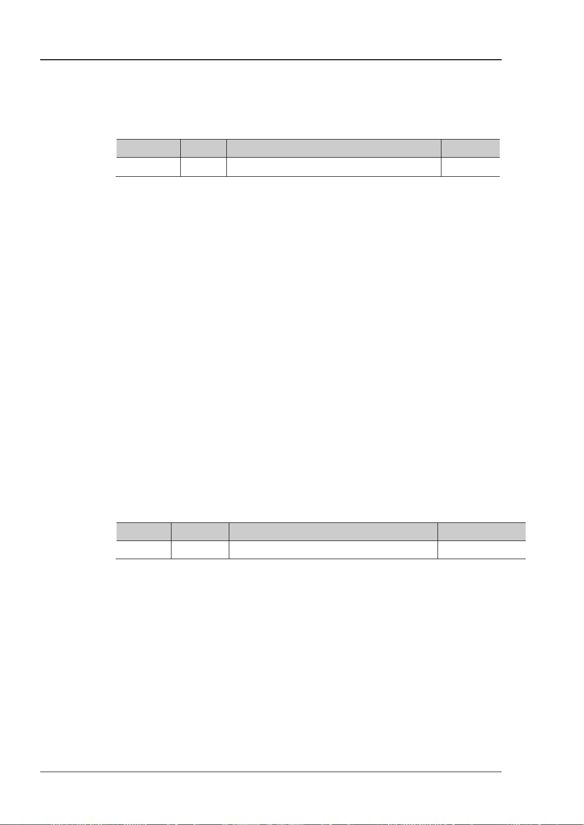
RIGOL Chapter 2 Command System
:TRIGger:COUPling?
Description
Select or query the trigger coupling type.
Name
Type
Range
Default
<couple>
Discrete
{AC|DC|LFReject|HFReject}
DC
HFReject: reje ct the high frequency components (higher than 75 kHz).
Format
Example
:TRIGger:COUP li ng LFRe je c t
Description
Query the current trigger status.
Format
:TRIGger:SWEep?
Description
Set or query the trigger mode.
<sweep>
Discrete
{AUTO|NORMal|SINGle}
AUTO
when the trigger condition is met and then stops.
Format
Example
:TRIGger:SWEep SINGle
:TRIGger:COUPling
Syntax :TRIGger:COUPling <couple>
Parameter
Explanation This command is only applicable to the edge trigger.
AC: block all the DC compo nents and attenuat e signals lower than 75 kHz.
DC: allow DC and AC components into the trigger path.
LFReject: block the DC components and reject the low frequency components (lower
than 75 kHz).
Return
The query returns AC, DC, LFR or HFR.
:TRIGger:STATus?
Syntax :TRIGger:STATus?
Return
The query returns TD, WAIT, RUN, AUTO or STOP.
:TRIGger:SWEep
Syntax :TRIGger:SWEep <sweep>
Parameter
Explanation AUTO: auto trigger. No matter whether the trigger condition is met, there is always
Name Type Range Default
waveform display.
NORMal: normal trigger. Display waveform when the trigger condition is met;
otherwise, the oscilloscope holds the original waveform and waits for the next trigger .
SINGle: single trigger. The oscilloscope waits for a trigger and displays the waveform
Return
The query returns AUTO, NORM or SING.
2-84 DS1000Z Programming Guide
Page 99
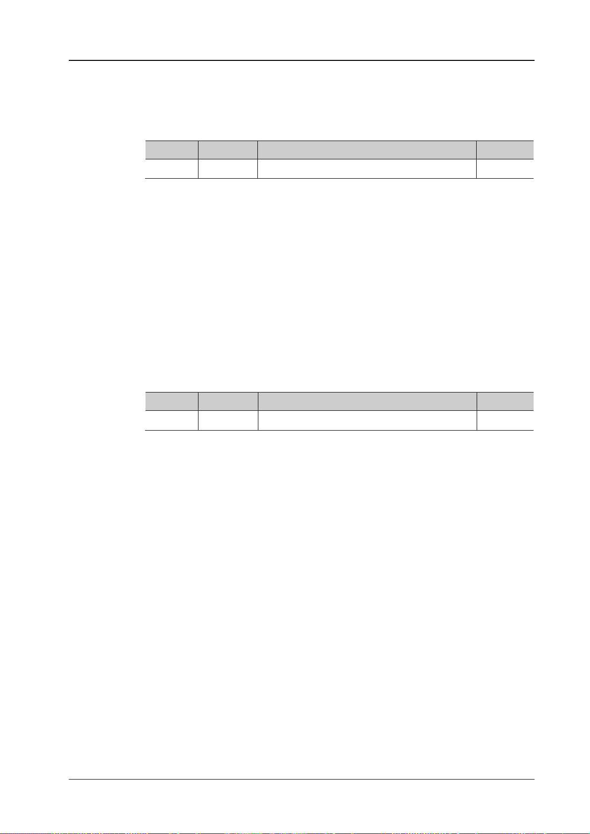
Chapter 2 Command System RIGOL
:TRIGger:HOLDoff?
Description
Set or query the trigger holdoff time. The default unit is s.
Name
Type
Range
Default
<value>
Real
16ns to 10s
16ns
When the trigger type is video, RS232, I2C or SPI, this setting will be not available.
Format
:TRIGger:HOLDoff? /*The query returns 2.000000e-07*/
Description
Enable or disable the noise rejection, or query the status of the noise rejection.
Name
Type
Range
Default
Explanation
Noise rejection reduces the possibility of noise trigger.
Example
:TRIGger:NREJect ON
:TRIGger:HOLDoff
Syntax :TRIGge r:HOLDoff <value>
Parameter
Explanation Trigger holdoff can be used to stably trigger the complex waveforms (such as pulse
series). Holdoff time is the time that the oscilloscope waits before re-arming the
trigger circuitry. The oscilloscope will not trigger until the holdoff time expires.
Return
Example
The query retuns the trigger holdoff time in scientific notation.
:TRIGger:HOLDoff 0.0000002 /*Set the trigger holdoff time to 200ns*/
:TRIGger:NREJect
Syntax :TRIGger:NREJect <bool>
:TRIGger:NREJect?
Parameter
<bool> Bool {{0|OFF}|{1|ON}} 0|OFF
Return
Format
The query returns 0 or 1.
DS1000Z Programming Guide 2-85
Page 100
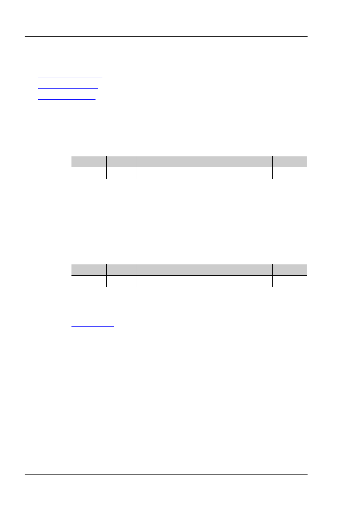
RIGOL Chapter 2 Command System
:TRIGger:EDGe:SOURce?
Description
Set or query the trigger source in edge trigger.
Name
Type
Range
Default
Format
Example
:TRIGger:EDGe:SOURce CHANnel1
:TRIGger:EDGe:SLOPe?
Description
Set or query the edge type in edge trigger.
Name
Type
Range
Default
<slope>
Discrete
{POSitive|NEGative|RFALl}
POSitive
Format
Example
:TRIGger:EDGe:SLOPe NEGative
Command
:TRIGger:EDGe
Command List:
:TRIGger:EDGe:SOURce
:TRIGger:EDGe:SLOPe
:TRIGger:EDGe:LEVel
:TRIGger:EDGe:SOURce
Syntax :TRIGger :EDGe:SOURce <s o urce>
Parameter
<source> Discrete {CHANnel1|CHANnel2|CHANnel3|CHANnel4|AC} CHANnel1
Return
The query returns CHAN1, CHAN2, CHAN3, CHAN4 or AC.
:TRIGger:EDGe:SLOPe
Syntax :TRIGger:EDGe:SLOPe <slope>
Parameter
Return
Related
The query returns POS, NEG or RFAL.
:TRIGger:MODE
2-86 DS1000Z Programming Guide
 Loading...