

Page 1

RIGOL
User’s Guide
DS1000Z Series Digital Oscilloscope
Aug. 2013
RIGOL Technologies, Inc.
Page 2

Page 3

RIGOL
I
Guaranty and Declaration
Copyright
© 2013 RIGOL Technologies, Inc. All Rights Reserv ed.
Trademark Information
RIGOL is a registered trademark of RIGOL Technologies, Inc.
Publication Number
UGA17101-1112
Notices
RIGOL products are protected by patent law in and outside of P.R.C.
RIGOL reserves the right to modify or change parts of or all the specifications
and pricing policies at company’s sole decision.
Information in this publication replaces all previously corresponding material.
RIGOL shall not be liable for losses caused by either incidental o r consequenti al
in connection with the fu r nis hing , use or perfo rman ce of this manual as well as
any information contained.
Any part of this document is forbidden to be copied or photocopi ed or
rearranged without prior written approval of RIGOL.
Product Certification
RIGOL guar antees this pr oduct confo rms to the national and industrial stan dar ds in
China as well as the ISO9001:2008 standard and the ISO14001:2004 standard.
Other international standard conformance certification is in progress.
Contact Us
If you have any problem or requirement when using our products, please contact
RIGOL Technologies, Inc. or your local distributors, or visit: www.rigol.com.
DS1000Z User’s Guide
Page 4

RIGOL
II
Safety Requirement
General Safety Summary
Please review the following safety precautions carefully before putting the
instrument into operation so as to avoid any personal injuries or damages to the
instrument and any product connecte d to it. To prevent potential haza rds, please use
the instrument only specified by this manual.
Use Proper Power Cord.
Only the power cord designed for the instrument and authorized by local coun t ry
could be used.
Ground The Instrument.
The instrument is grounded through the Protective Earth lead of the power cord. To
avoid electric shock, it is e ssential t o connect the ea rth terminal of power cord to the
Protective Earth terminal before any inputs or outputs.
Connect the Probe Correctly.
Do not connect the ground lead to high voltage since it has the isobaric electric
potential as ground.
Observe All Terminal Ratings.
To avoid fire or shock hazard, observe all r atings and markers on the instrument and
check your manual for more information about ratings before connecting.
Use Proper Overvoltage Protection.
Make sure that no overvoltage (such as that caused by a thunderstorm) can reach
the product, or else th e op erator might expose to danger of electrical shock.
Do Not Operate Without Covers.
Do not operate the instrument with covers or panels removed.
Use Proper Fuse.
Please use the specified fuses.
DS1000Z User’s Guide
Page 5

RIGOL
III
Avoid Circuit or Wire Exposure.
Do not touch exposed junctions and components when the unit is powered.
Do Not Operate With Suspected Failures.
If you suspect damage occurs to the instrument, have it inspected by qualified
service personnel before further oper at ions. Any maintenance, adjustment or
replacement especially to circuits or accessories must be performed by RIGOL
authorized personnel.
Keep Well Ventilation.
Inadequate ventilation may cause increasing of temperature or damages to the
device. So please keep well ventilated and inspect the intake and fan regularly.
Do Not Operate in Wet Conditions.
In order to av oid short circuiting t o the interi or of the device or electric shock, please
do not operate in a humid environment.
Do Not Operate in an Explosive Atmosphere.
In order to avoid damages to the device or personal injuries, it is important to
operat e the dev ice away from an explosive atm osphere.
Keep Product Surfaces Clean and Dry.
To avoid the influence of dust and/or moisture in air, please keep the surface of
device clean and dry.
Electrostatic Prevention.
Operate in an electrostatic discharge protective area environment to avoid damages
induced by static discharges. Always ground both the internal and external
conductors of the cable to release static before connecting.
Handling Safety.
Please handle with care during transportation to avoid damages to buttons, knob
interfaces and other parts on the panels.
DS1000Z User’s Guide
Page 6
RIGOL
IV
CAUTION
indicates a potential dama ge to the inst rument or ot her property mi ght
Hazardous
Safety
Protective
Chassis
Test
Safety Terms and Symbols
Terms in this Ma n ual. These terms may appear in this manual:
WARNING
Warning state ments indicate the conditions or practices that could result i n
injury or loss of life.
Caution statements indicate the c onditions or practic es that coul d result i n
damage to this product or other property.
Terms on the Product. These terms may appear on the Product:
DANGER
WARNING indicates an injury or hazard may be accessible potentially.
CAUTION
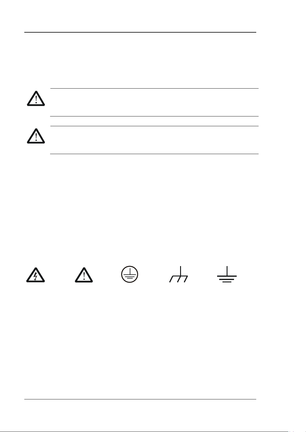
Symbols on the Product. These symbols may appear on the product:
indicates an injury or hazard may immediately happen.
occur.
Voltage
Warnning
Earth
Terminal
Ground
Ground
DS1000Z User’s Guide
Page 7
RIGOL
V
WARNING
Measurement Category
Measurement Category
DS1000Z series digital oscilloscopes can make measurements in Measurement
Category I.
This oscilloscope can only be used for measurements within its specified
measurement categories.
Measurement Category Definitions
Measurement category I is for measurements performed on circuits not directly
connected t o MA INS. Examples are me a s urements on ci rcuits not derived from
MAINS, and specially protected (internal) MAINS derived circuits. In the latter case,
transient stresses are variable; for that reason, the transient withstand capability of
the equipment is made known to the user.
Measurement category II is for measurements performed on circuits directly
connected to the low volta ge install ation. Exa mples a re measure ments o n house hold
appliances, portable tools and similar equipment.
Measurement category III is for measurements performed in the building installat ion.
Examples are measurements on distribution boards, circuit-breakers, wiring,
including cables, bus-bars, junction boxes, switches, socket-outlets in the fixed
installation, and equipment for industrial use and some other equipment, for
example. Stationary motors with permanent connection to the fixed installation.
Measurement category IV is for measurements performed at the source of the
low-voltage installation. Examples are electricity meters and measurements on
primary overcurrent protection devices and ripple control units.
DS1000Z User’s Guide
Page 8
RIGOL
VI
WARNING
Ventilation Requirement
This oscilloscope uses fan to force cooling. Please make sure that the air intake and
exhaust areas are free from obstructions and have free air. When using the
oscilloscope in a bench-top or rack setting, provide at least 10 cm clearance beside,
above and behind the instrument for adequate ventilation.
Inadequate ventilation may cause temperature increase which would
damage the instrument. So please keep the instrument well ventilated
during operation and inspect the intake and fan regularly.
DS1000Z User’s Guide
Page 9
RIGOL
VII
o avoid short ci rcuit insid e the instru ment or e lectric s hock, please do n ot
WARNING
reach the product, or else the operator might expose to da nge r of e lectric
Working Environment
Temperature
Operating: 0℃ to +50℃
Non-operating: -40℃ to +70℃
Humidity
0℃ to +30℃:≤95% relative humidity
+30℃ to +40℃:≤75% relative humidity
+40℃ to +50℃:≤45% relative humility
WARNING
T
operat e in humid environment.
Altitude
Operating: less than 3 km
Non-operating: less than 15 km
Installation (overvoltage) Category
This product is powered by mains conforming to installation (overvoltage) category
II.
Make sure that no overvoltage (such as that caused by thunderbolt) can
shock.
Installation (overvoltage) Category Definitions
Installation (overvoltage) category I refers to signal level which is applicable to
equipment measurement terminals connected to the source circuit. In these
terminals, precautions are done to limit the transient voltage to the corresponding
low level.
Installation (overvoltage) category II refers to the local power distribution level
which is applicable to equipment connected to the AC line (AC power).
DS1000Z User’s Guide
Page 10

RIGOL
VIII
Pollution Degree
Degree 2
Pollution Degree Definitions
Pollution degree 1: No pollution or only dry, non-conductive pollution occu rs. The
pollution has no influence. For example: a clean room or air-conditioned office
environment.
Pollution degree 2: Normally only dry, non-conductive pollution occurs. Occasionally
a temporary conductivity caused by condensation may occur. For example: general
indoor environment.
Pollution degree 3: Conductive pollution occurs, or dry, non-conductive pollution
occurs which becomes conductive due to condensation which is expected. For
example: Sheltered outdoor environment.
Pollution degree 4: Pollution that generates persistent conductivity through
conductive dust, rain, or snow. For example: outdoor locations.
Safety Class
Class 1 – Grounded Product
DS1000Z User’s Guide
Page 11
RIGOL
IX
General Care and Cleaning
General Care:
Do not store or leave the inst rument at places where the instrument will be exposed
to direct sunlight for long periods of time.
Cleaning:
Clean the instrument regularly according to its operating conditions. To clean the
exterior surface:
1. Disconnect the instrument from all power sources.
2. Clean the loose dust on the outside of the instrument with a lint - free cloth (with
mild detergent or water). When cleaning t he LCD, ta k e c are to avoid scarifying
it.
CAUTION
To avoid damages to the instrument, do not expose them to corrosive
liquids.
WARNING
To avoid injury resulting from short circuit, make sure the instrument is
completely dry before reconnecting it to a pow e r s ou r ce.
DS1000Z User’s Guide
Page 12

RIGOL
X
Environmental Consideratio ns
The following symbol indicates that this product complies with the applicable
European Union requirements according to Directive s 2002/96/EC on waste electrical
and electronic equipment (WEEE).
Product End-of-Life Handling
The equipment may contain substances that could b e ha rmful to the envi ronm ent o r
human health. In order to avoid release of such substances into the environment and
harm to human health, we e ncourage you to recycle this product in an appropriate
system that will ensure that most of the materials are reused or recycled
appropriately. Please contact your local authorities for disposal or recycling
information.
DS1000Z User’s Guide
Page 13

RIGOL
XI
DS1000Z Series Overview
DS1000Z is a high-performance digital oscilloscope developed on the basis of the
UltraVision technique. DS1000Z, featuring rather deep memory depth, ultra-wide
dynami c ra nge, super b wave f orm capt ure rate and all -round trigger functions, is an
invaluable debug instrument in v arious fields (such as communication, cosmonautics,
national defense, embedded system, computer, research and education) and is the
one with the most complete f unctions and most outs tanding spe cification among the
digital oscilloscopes with lower than 100 MHz bandwidth.
Main feature s:
100 MHz and 70 MHz bandwidth.
UltraVision technique.
1 GSa/s maximum real-time sample rate.
30,000 wfms/s (dots display) wavef orm capture rate.
Real-time hardware waveform recording, waveform playback functions. Up to
60,000 frames of waveform can be recorded.
24 Mpts maximum memory dep th (o ption) and 12 Mpts standard memory
depth.
Multi-degree gray scale display.
Low noise, 1 mV/div to 10 V/div ultra-wide vertical dynamic range .
7.0 inches , WVGA (800*480) 160,000 color TFT LCD, vivid picture, low power
consumption and long service life.
Adjustable brightness of analog channel waveform.
Auto setting of waveform display (AUTO).
15 kinds of trigger functions including multiple protocol triggers.
Standard parallel decoding and multiple serial decoding options.
Auto measurements of 24 waveform parameters and measurement functions
with statistic.
Precise delayed sweep function.
Built-in FFT function.
Pass/Fail test function.
Multiple waveform math operation functions.
Built-in dual-channel, 25 MHz signal source function (only available for
DS1000Z-S).
Standard configuration interfaces: USB Device, USB Host, LAN and GPIB
(optional).
Conform to LXI-C instrument standards. Enabl e quick, economic a nd efficient
DS1000Z User’s Guide
Page 14

RIGOL
XII
creation and reconfiguration of test system.
Support remote command control.
Embedded help enables easier information access.
Support multiple languages and Chinese/English input.
Novel and delicate industrial design and easier operation.
DS1000Z User’s Guide
Page 15

RIGOL
XIII
Chapter 1 Quick Start
Provide informat ion about preparations befo re using the instrument and a brief
Chapter 2 To Set the Vertical System
Introduce the functions of the vertical system of the oscilloscope.
Chapter 3 To Set the Horizontal System
Introduce the functions of the horizontal system of the oscilloscope.
Chapter 4 To Set the Sample System
Introduce the functions of the sample system of the oscilloscope.
Chapter 5 To Trigger the Oscilloscope
Introduce the trigger mode, trigger coupling, trigger holdoff, external trigger and
Chapter 6 To Make Measurements
Introduce how to make math operation, cursor measurement and auto
Chapter 7 Protocol Decoding
Introduce how to decode the input signal using those common protocols.
Chapter 8 Reference Waveform
Introduce how to compare the input waveform with the reference wavefo rm.
Chapter 9 Pass/Fail Test
Introduce how to monitor the input signal using the Pass/Fail test.
Chapter 10 Waveform Record
Introduce how to analyze the input signal using waveform record.
Chapter 11 Display Control
Introd uce how to control the display of the oscilloscope.
Chapter 12 Signal Source
Introduce how to use the built-in signal source.
Chapter 13 Store and Recall
Introduce how to store and recall the measurement result and the setting of the
oscilloscope.
Document Overview
introduction of the instrument.
various trigger types of the oscilloscope.
measurement.
DS1000Z User’s Guide
Page 16
RIGOL
XIV
Chapter 14 System Function Setting
Introduce how to set the remote interface and system-related functions.
Chapter 15 Remote Control
Introduce how to control the oscilloscope remotely.
Chapter 16 Troubleshooting
Introduce how to deal with common failures of the oscilloscope.
Chapter 17 Specifications
Provide the specifications and general specifications of the oscilloscope.
Chapter 18 Appendix
Provide common information such as options and accessories.
Logo
Knob
Logo
Knob
Multi-function
Knob
Vertical Scale
Knob
SCALE
Horizontal
POSITION
Vertical Position
POSITION
Horizontal
Trigger Level
Format Conventions in this Manual:
Front panel key: denoted by the format of “Text Box + Button Name (Bold)”, for
example, Storage.
Menu softkey: denoted by the format of “Character Shading + Menu Word (Bold)”,
for example, Storage.
Operation steps: denoted by the arrow “”, for example, Storage Storage.
Cross-reference: denoted by the blue font with bold and underline, for example, 12
Signal Source.
Knob:
HORIZONTAL
VERTICAL SCALE
VERTICAL
Scale Knob
HORIZONTAL
TRIGGER LEVEL
Position Knob
Knob
Knob
DS1000Z User’s Guide
Page 17
RIGOL
XV
Content Con v entions in th is Man ual:
This manual takes DS1104 Z -S for example a nd the de scriptions here ha ve containe d
all the functions and performances of other models. DS1000Z series includes the
following models:
Model Analog bandwidth Channels Cahnnels for signal source
DS1104Z 100 MHz 4
DS1074Z 70 MHz 4
——
——
DS1104Z-S 100 MHz 4 2
DS1074Z-S 70 MHz 4 2
DS1000Z User’s Guide
Page 18

RIGOL
XVI
Contents
Guaranty and Declaration ......................................................................... I
Safety Requirement ................................................................................. II
General Safety Summary........................................................................... II
Safety Terms and Symbols ....................................................................... IV
Measurement Category ............................................................................. V
Ventilation Requirement ........................................................................... VI
Working Enviro nment ............................................................................. VII
General Care and Cleaning ....................................................................... IX
Environmental Considerations .................................................................... X
DS1000Z Series Overview ...................................................................... XI
Document Overview ............................................................................ XIII
Chapter 1 1 Quick Start ...................................................................... 1-1
General Inspection ................................................................................. 1-2
Appearance and Dim ensions ................................................................... 1-3
To Prepare the Oscilloscope for Use ......................................................... 1-4
To Adjust the Supporting Legs .......................................................... 1-4
To Connect to Power Supply ............................................................. 1-5
Power-on Inspection ........................................................................ 1-6
To Connect the Probe ....................................................................... 1-7
Function Inspection ......................................................................... 1-8
Probe Compensation ...................................................................... 1-10
Front
Panel Overview ........................................................................... 1-11
Rear Panel Overview ............................................................................ 1-12
Front Panel Function Overview .............................................................. 1-14
VERTICAL ..................................................................................... 1-14
HORIZONTAL ................................................................................ 1-15
TRIGGER ...................................................................................... 1-15
CLEAR .......................................................................................... 1-16
RUN/STOP .................................................................................... 1-16
SINGLE ......................................................................................... 1-16
AUTO ........................................................................................... 1-16
Knob ............................................................................................ 1-17
DS1000Z User’s Guide
Page 19

RIGOL
XVII
Print ............................................................................................. 1-18
User Interface ...................................................................................... 1-19
To Use the Security Lock ....................................................................... 1-23
To Use the Built-in Help System ............................................................. 1-24
Chapter 2 2 To Set the Vertical System .............................................. 2-1
To Enable the Channel ........................................................................... 2-2
Channel Coupling .................................................................................. 2-3
Bandwidth Limit .................................................................................... 2-3
Probe Ratio ........................................................................................... 2-4
Waveform Inv e rt ................................................................................... 2-5
Vertical Scale ........................................................................................ 2-5
Vertical Expansion ................................................................................. 2-6
Amplitude Unit ...................................................................................... 2-6
Channel Label ....................................................................................... 2-7
Chapter 3 3 To Set the Horizontal System .......................................... 3-1
Delayed Sweep ..................................................................................... 3-2
Time Base Mode.................................................................................... 3-4
YT Mode ........................................................................................ 3-4
XY Mode ........................................................................................ 3-5
Roll Mode ....................................................................................... 3-8
Chapter 4 4 To Set the Sam p le System ............................................... 4-1
Acquisition Mode ................................................................................... 4-2
Normal .......................................................................................... 4-2
Average ......................................................................................... 4-2
Peak Detect .................................................................................... 4-4
High Resolution .............................................................................. 4-4
Sin(x)/x ................................................................................................ 4-4
Sample Rate ......................................................................................... 4-5
Memory Depth ...................................................................................... 4-7
Chapter 5 5 To Trigger the Oscilloscope ............................................. 5-1
Trigger Source ...................................................................................... 5-2
Trigger Mode ........................................................................................ 5-3
Trigger Coupling .................................................................................... 5-5
Trigger Holdoff ...................................................................................... 5-6
Noise Rejection ..................................................................................... 5-7
DS1000Z User’s Guide
Page 20

RIGOL
XVIII
Trigger Type .......................................................................................... 5-8
Edge Trigger ................................................................................... 5-9
Pulse Trigger ................................................................................. 5-10
Slope Trigger ................................................................................. 5-12
Video Trigger................................................................................. 5-15
Pattern Trigger .............................................................................. 5-17
Duration Trigger ............................................................................ 5-19
Setup/Hold Trigger......................................................................... 5-21
TimeOut Trigger (Option) ............................................................... 5-23
Runt Trigger (Option) ..................................................................... 5-25
Windows Trigger (Option) ............................................................... 5-28
Delay Trigger (Option).................................................................... 5-30
Nth Edge Trigger (Option) .............................................................. 5-32
RS232 Trigger (Option) .................................................................. 5-34
I2C Trigger (Option) ....................................................................... 5-36
SPI Trigger (Option) ....................................................................... 5-39
Trigger Output Connector...................................................................... 5-41
Chapter 6 6 To Mak e Measurements .................................................. 6-1
Math Operation ...................................................................................... 6-2
Addition .......................................................................................... 6-2
Substraction .................................................................................... 6-3
Multiplication ................................................................................... 6-3
Division .......................................................................................... 6-4
FFT ................................................................................................ 6-6
“AND” Operation .............................................................................. 6-9
“OR” Operation .............................................................................. 6-10
“XOR” Operation ............................................................................ 6-11
“NOT” Operation............................................................................ 6-12
Integrate ...................................................................................... 6-13
Differentiate .................................................................................. 6-13
Square Root .................................................................................. 6-14
Base 10 Logarithm ......................................................................... 6-15
Natural Logarithm .......................................................................... 6-15
Exponential ................................................................................... 6-16
Absolute Value .............................................................................. 6-17
Auto Measurement ............................................................................... 6-18
Quick Measurement after AUTO ...................................................... 6-18
DS1000Z User’s Guide
Page 21

RIGOL
XIX
One-key Measurement of 24 Parameters .......................................... 6-19
Frequency Counter Measurement .................................................... 6-24
Measurement Setting ..................................................................... 6-25
To Clear the Measurement .............................................................. 6-26
All Measurement ............................................................................ 6-27
Statistic Function ........................................................................... 6-28
Cursor Measurement............................................................................. 6-29
Manual Mode ................................................................................. 6-30
Track Mode ................................................................................... 6-33
Auto Mode .................................................................................... 6-35
Chapter 7 7 Protocol Decoding ........................................................... 7-1
Parallel Decoding ................................................................................... 7-2
RS232 Decodi n g (Option) ....................................................................... 7-5
I2C Decoding (Option) .......................................................................... 7-11
SPI Decoding (Option) .......................................................................... 7-15
Chapter 8 8 Reference Waveform ....................................................... 8-1
To Enable REF Function.......................................................................... 8-2
To Select RE F Source ............................................................................. 8-2
To Adjust REF Waveform Display ............................................................. 8-3
To Save to Internal Memory ................................................................... 8-3
To Set the Color .................................................................................... 8-3
To reset the REF waveform ..................................................................... 8-3
To Export to Internal or External Memory ................................................ 8-4
To Import from Inter nal or External Mem or y ............................................ 8-4
Chapter 9 9 Pass/Fail Test .................................................................. 9-1
To Enable Pass/Fail Test ......................................................................... 9-2
To Select Source.................................................................................... 9-2
Mask Range .......................................................................................... 9-2
Test and Ouput ..................................................................................... 9-3
To Save the Test Mask ........................................................................... 9-4
To Load the Test Mask ........................................................................... 9-4
Chapter 10 10 Waveform Record ................................................. 10-1
Playback Setting ................................................................................... 10-2
Record Setting ..................................................................................... 10-3
Chapter 11 11 Display Control ...................................................... 11-1
DS1000Z User’s Guide
Page 22

RIGOL
XX
To Select the Display Type .................................................................... 11-2
To Set the Persistence Time .................................................................. 11-3
To Set the Waveform Intensity .............................................................. 11-5
To Set the Screen Grid .......................................................................... 11-5
To Set the Grid Brightness..................................................................... 11-5
To Set the Menu Display ....................................................................... 11-5
Chapter 12 12 Signal Source ........................................................ 12-1
To Output Ba sic Waveform .................................................................... 12-2
To Output Sine Waveform ............................................................... 12-2
To Output Square Waveform ........................................................... 12-4
To Output Ramp Waveform ............................................................. 12-4
To Output Pulse Waveform ............................................................. 12-5
To Output DC Waveform ................................................................. 12-5
To Output Noise Waveform ............................................................. 12-6
To Output Built-In Waveform ................................................................. 12-7
To Output Arbitrary Waveform ............................................................. 12-12
To Select Waveform ..................................................................... 12-14
To Create Waveforms ................................................................... 12-14
To Edit Waveforms ....................................................................... 12-17
Modulation ........................................................................................ 12-19
Chapter 13 13 Store and Recall ................................................... 13-1
Storage System .................................................................................... 13-2
Storage Type ....................................................................................... 13-3
Internal Storage and Recall ................................................................... 13-5
External Storage and Recall ................................................................... 13-6
Disk Management ................................................................................ 13-7
To Select File Type ......................................................................... 13-8
To Create a New File or Folder ........................................................ 13-9
To Delete a File or Folder .............................................................. 13-12
To Rename a File or Folder ........................................................... 13-13
To Clear the Local Memory ........................................................... 13-13
Factory.............................................................................................. 13-14
Chapter 14 14 System Function Setting ....................................... 14-1
Remote Int e rface Configuration ............................................................. 14-2
LAN Setting ................................................................................... 14-2
USB Device ................................................................................... 14-6
DS1000Z User’s Guide
Page 23

RIGOL
XXI
System-related ..................................................................................... 14-7
Sound ........................................................................................... 14-7
Language ...................................................................................... 14-7
System Informat i on ........................................................................ 14-8
Power-on Recall ............................................................................. 14-8
Self-calibration ............................................................................... 14-9
Option Management ..................................................................... 14-10
Chapter 15 15 Remote Control ..................................................... 15-1
Remote Control via USB ........................................................................ 15-2
Remote Control via LAN ........................................................................ 15-6
Chapter 16 16 Troubleshooting .................................................... 16-1
Chapter 17 17 Specifications ........................................................ 17-1
Chapter 18 18 Appendix ............................................................... 18-1
Appendix A: Accessories and Options ..................................................... 18-1
Append i x B: Warranty ........................................................................... 18-2
Appendix C: Any Question or Comment? ................................................. 18-3
Chapter 19 Index .............................................................................. 1
DS1000Z User’s Guide
Page 24

Page 25

Chapter 1 Quick Start RIGOL
1-1
Chapter 1 Quick Start
This chapter introduces the preparations when using the oscilloscope for the first
time, the front panel, rear panel and user inte rf ace of the oscillosco pe as well as the
using method of the built-in help system.
The contents of this chapter:
General Inspection
Appearance and Dimensions
To Prepare the Oscilloscope for Use
Front Panel Overview
Rear Panel Overview
Front Panel Function Overview
User Interface
To Use the Security Lock
To Use the Built-in He lp Syst em
DS1000Z User’s Guide
Page 26

RIGOL Chapter 1 Quick Start
1-2
General Inspection
1. Inspect the shipping container for damage.
Keep the damaged shipping container or cushioning material until the contents
of the shipment have been checked for completeness and the instrument has
passed both ele ctrica l and mechanical tests.
The consigner or carrier shall be liable for the damage to instrument resulting
from shipment. RIGOL woul d n ot be responsible for free maintenance/rework
or replacement of the unit.
2. Inspect the instrument.
In case of any damage, or defect, or failure, notify your RIGOL sales
representative.
3. Check the Accessories
Please check the accessories according to the packing l is t s. If t he acces sories
are incomplete or damaged, plea se contact your RIGOL sales representative.
DS1000Z User’s Guide
Page 27
Chapter 1 Quick Start RIGOL
1-3
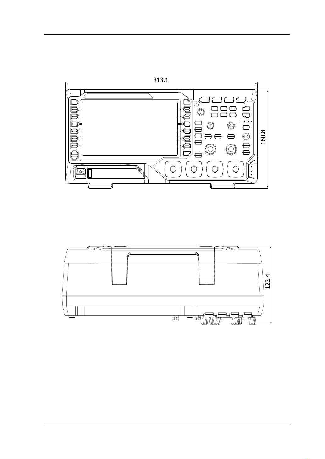
Appearance and Dimensions
Figure 0-1 Front View Unit: mm
Figure 0-2 Top View Unit: mm
DS1000Z User’s Guide
Page 28
RIGOL Chapter 1 Quick Start
1-4
To Prepare the Oscilloscope for Use
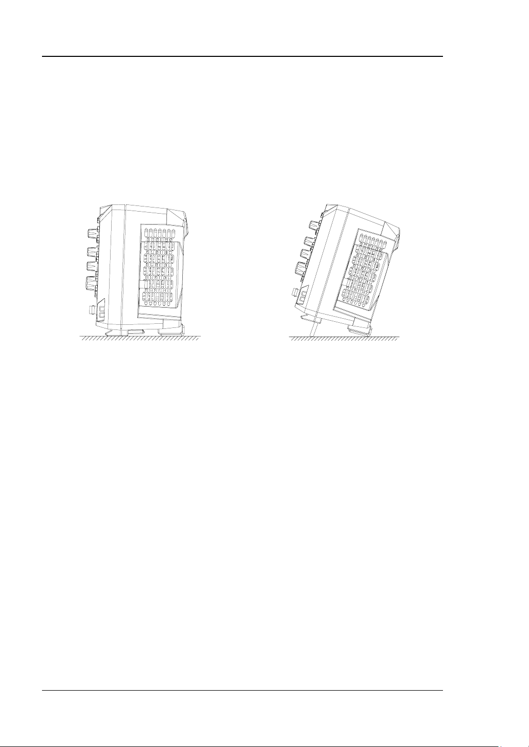
To Adjust the Supporting Legs
Adjust the supporting legs properly to use them as stands to tilt the oscilloscope
upwards for stable placement of the oscilloscope as well as better operation and
observation.
Figure 0-3 To Adjust the Supporting Legs
DS1000Z User’s Guide
Page 29
Chapter 1 Quick Start RIGOL
1-5
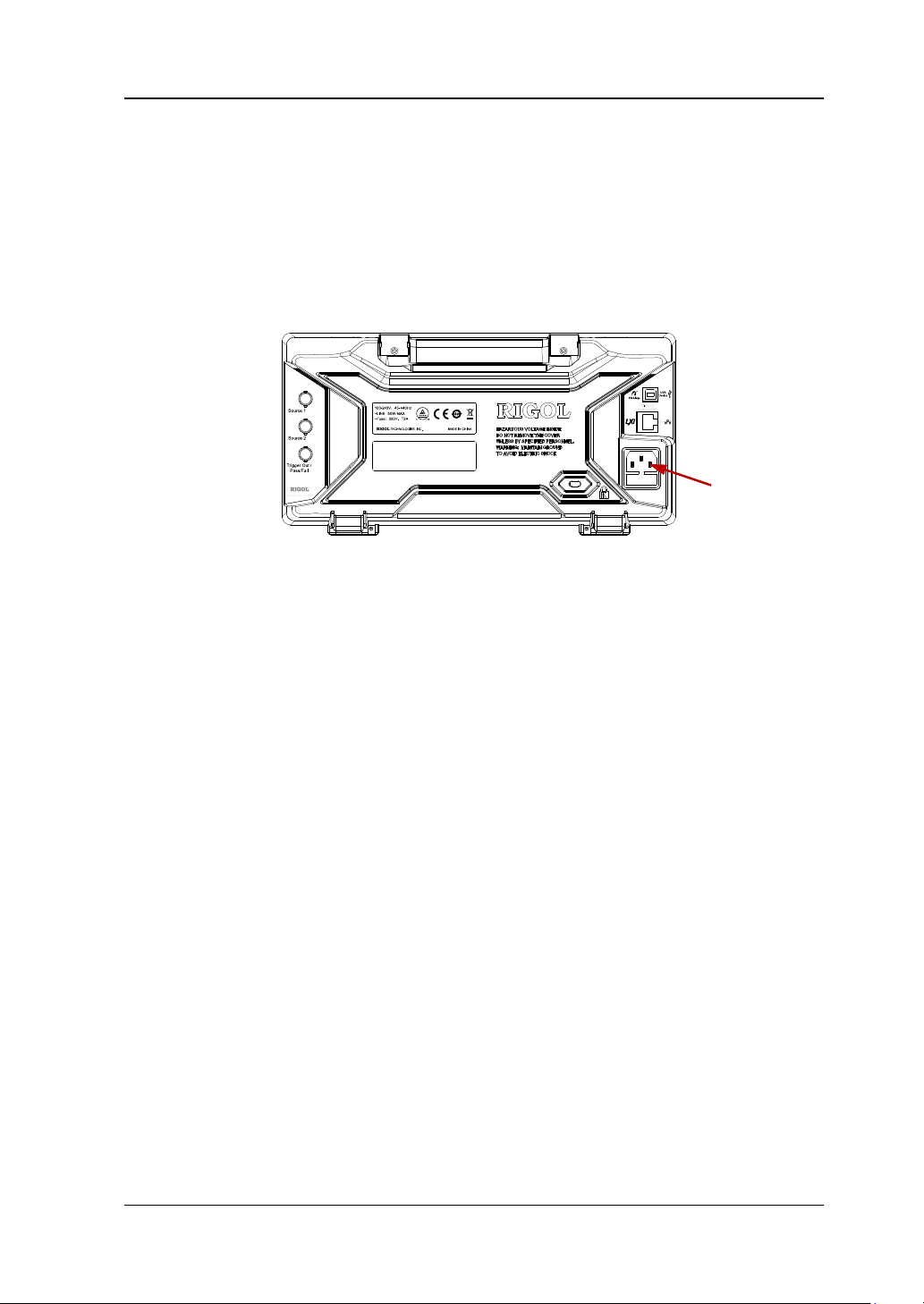
To Connect to Power Supply
The power requirements of DS1000Z are 100-240 V, 45-440 Hz. Please use the
power cord supplied with the accessories to connect the oscilloscope to the power
source.
Power Socket
Figure 0-4 To Connect to Power Source
DS1000Z User’s Guide
Page 30

RIGOL Chapter 1 Quick Start
1-6
Power-on Inspection
When the oscilloscope is energized, press the power key
of the front panel to start the oscilloscope. During the start-up process, the
oscilloscope performs a series of self-tests and after the self-test is finished, the
welcome screen is displayed and you can view the Option Type, Option name, Option
Edition and Left time of the option currently installed in the “Installed Options”
pop-up dialog box on the screen. When the instrument is shipped, a trial version of
the option is provided and the left time is about 2000 minutes.
at the lower-left corner
DS1000Z User’s Guide
Page 31

Chapter 1 Quick Start RIGOL
1-7
To Connect the Probe
RIGOL provides passive probes for the DS1000Z series oscilloscopes. For detailed
technical information of the probes, please refer to the corresponding Probe User’s
Guide. The following are the probes recommended for this oscilloscope.
Model Description
RP3300
RP3500A 500 MHz, passive probe, optional
Connect the Probe:
1. Connect the BNC terminal of the probe to a channel BNC connector of the
oscilloscope at the front panel.
2. First connect the ground al ligator clip of the probe to t he circuit ground terminal
and then connect the probe tip to the circuit point to be tested.
350 MHz, passive probe, standard
Figure 0-5 To Connect the Probe
DS1000Z User’s Guide
Page 32

RIGOL Chapter 1 Quick Start
1-8
o avoid electric shock during the use of probe, please make sure that
Function Inspection
1. Press Storage Default to restore the instrument to its default configuration.
2. Connect the ground alligator clip of the probe to the “Ground Terminal” under
the probe compensation signal output terminal.
3. Use the probe to connect the input terminal of CH1 of the oscilloscope and the
“Compensation Signal Output Terminal” of the probe.
Compensation Signal Output Terminal
Ground Terminal
Figure 0-6 To Use the Compensation Signal
4. Press AUTO.
5. Observe the wa veform on the display. In normal condition, the display should be
a square waveform as shown in the figure below:
Figure 0-7 Square Waveform
6. Use the same method to test the other channels. If the square waveforms
actually shown do not match that in the figure above, please perform “
Compensation” in the next section.
WARNING
T
the insulated wire of the probe is in good condition and do not touch
the metallic part of the probe when the probe is connected to high
voltage source.
Probe
DS1000Z User’s Guide
Page 33

Chapter 1 Quick Start RIGOL
1-9
Tip
probe compensation adjustment and can not be used for calibration.
The signal output from the probe compensation connector can only be used for
DS1000Z User’s Guide
Page 34

RIGOL Chapter 1 Quick Start
1-10
Probe Compensation
When the probes are used for the first time, you should compensate the probes to
match the input channels of the oscilloscope. Non-compensated o r po orly
compensate d probes may cause measurement inaccuracy or error. The probe
compensation procedures are as follows.
1. Perform steps 1, 2, 3 and 4 of “
2. Check the waveforms displayed and compare them with the following.
Over compensated Perfectly compensated Under compensated
Figure 0-8 Probe Compensation
3. Use a nonmetallic driver to adjust the low-frequen c y compensation adjustment
hole on the probe until the waveform displayed is as the “Perfectly
compensated” in the figure above.
Function Inspection” in the previous section.
DS1000Z User’s Guide
Page 35

Chapter 1 Quick Start RIGOL
1-11
Front Panel Overview
1 2
10 11 12 13 14 15 16 17
Figure 0-9 Front Panel Overview
Table 0-1 Front Panel Descri ption
3 4 5 6 7 8 9
No. Description No. Description
1 Menu 10 Power Key
2 LCD 11 USB HOST
3 Multi-function Knob 12 Function Setting Menu Softkeys
4 Function Menu Keys 13 Analog Channel Input Area
5 CLEAR 14 VERTICAL
6 AUTO 15 HORIZONTAL
7 RUN/STOP 16 TRIGGER
8
SINGLE
17 Probe Compensation Signal Output
Terminal/Ground Terminal
9 Help&Print -- --
DS1000Z User’s Guide
Page 36

RIGOL Chapter 1 Quick Start
1-12
Rear Panel Overview
4 5 6 7 8
1 2 3
Figure 0-10 Rear Panel Overview
1. Handle
Pull up the handle vertically for easy carrying of the instrument. When you do
not need the handle, press it down.
2. LAN
Connect the instrument to the network via this interf ace fo r remot e cont rol. Thi s
oscilloscope conforms to the LXI-C class instrument standards and can quic kly
build test system with other instruments.
3. USB DEVICE
PictBridge printer or PC can be connected via this interface to print waveform
data or control the instrument using PC software or user-defined programming.
4. Trigger Out/Pass/Fail
Trigger Out: the oscilloscope outputs a signal that can reflect the current
capture rate of the oscilloscope at each trigger via this connector and connect
the signal to a waveform display instrument to measure the frequency of the
DS1000Z User’s Guide
Page 37

Chapter 1 Quick Start RIGOL
1-13
signal and the result is equal to the current capture rate.
Pass/Fail: there will be out put a negative pulse signal when failed waveforms
are detected by the oscilloscope. Connect this si gnal t o other control s yst ems t o
view the test result conveniently. There will be output a 3.3 V CMOS high level
when no failed waveform is detected by the oscilloscope.
5. Signal Output
When the output of Source1 and Source2 are enabled, the signal currently set
can be output to the analog input terminal of the oscilloscope or external
devices connected to them through the [Source1] and [Source2] connectors
at the rear panel.
6. Lock Hole
You can lock the instrument to a fixed location using the security lock (please
buy it yourself) via the lock hole.
7. Fuse
If a new fuse is required, please use the specified fuse (250V, T2A).
a) Turn off the instrument and remove the power cord.
b) Insert a straight screwdriver int o the slot at the power socket and prize out
the fuse seat gently.
c) Take out the fuse and replace it with specified fuse, and then install the fuse
seat to the original position.
8. AC Power Socket
AC power input terminal. The power requirements of this oscilloscope are
100-240 V, 45-440 Hz. Use the power cord provided with the accessories to
connect the instrument to AC power. Then, you can press the power key at the
front panel to start the instrument.
DS1000Z User’s Guide
Page 38

RIGOL Chapter 1 Quick Start
1-14
are marke d by di fferent colors w hich are also
Front Panel Function Overview
VERTICAL
CH1, CH2, CH3, CH4: analog input chan nels. The 4
channels
used to mark both the corresponding waveforms on
the screen and the channel input connectors. Press
any key to open t he corre sponding channel menu a nd
press again to turn off the channel.
MATH: press this key to open the math operation
menu under which add, subtract, multiply , divide , FFT,
A&&B, A||B, A^B, !A, intg, diff, sqrt, lg, ln, exp and
abs are prov ided.
REF: press this key to enable the reference waveform function to compare the
waveform actually tested with the reference waveform.
Source: pre ss this key to enter the source setting interface. You can turn on or off
the outputs of the [Source1] and [Source2] connectors at the rear panel, edit the
output signal and view the current signal status (such as the frequency, amplitude
and phase).
Vertical
waveform. Turn clockwise to increase the position and turn counterclockwise to
decrease. During the modification, the waveform would move up and down and t he
position message (e.g.
change accordingly. Press down this knob to quickly reset the vertical position to
zero.
POSITION: modify the vertical position of the current channel
) at the lower-left corner of the screen would
VERTICAL
clockwise to decrease the scale and turn counterclockwise to increase. During the
modification, the amplitude of the waveform would enlarge or reduce and the scale
information (e.g.
accordingly. Press down this knob to quickly switch the vertical scale adjustment
modes between “Coarse” and “Fine”.
SCALE: modify the vertical scale of the current channel. Turn
) at the lower side of the screen would change
DS1000Z User’s Guide
Page 39

Chapter 1 Quick Start RIGOL
1-15
HORIZONTAL POSITION
the horizontal control menu under whi ch to turn o n
and turn counterclockwise to reduce the level.
During the modification, the trigger level line would move up and
change accordingly. Press down the knob to quickly reset the
HORIZONTAL
: modify the horizontal position.
The trigger point would move left or right relative to the center of
the screen when you turn the knob. During the modification,
waveforms of all the channels would move left or right and the
horizontal position message (e.g.
upper-right corner of the screen would change accordingly. Press
down this knob to quickly reset the horizontal position (or the
delayed sweep position).
MENU: press this key to open
or off the delayed sweep function, switch between different time base modes.
HORIZONTAL
reduce the time base and turn counte r clo ckwise to increase the time base. During
the modif ication, waveforms of all the channels will be displayed in expanded or
compressed mode and the time base message (e.g.
the screen would change accordingly. Press down this knob to quickly switch to
delayed sweep state.
SCALE: modify the horizontal time base. Turn clockwise to
) at the upper side of
) at the
TRIGGER
MODE: press this key to switch the trigger mode to Auto, Normal
or Single and th e corresponding state backlight of the current
trigger mode would be illuminated.
TRIGGER
increase the level
down and the value in the trigger level message box (e.g.
trigger level to zero point.
DS1000Z User’s Guide
LEVEL: modify the trigger level. Turn clockwise to
) at the lower-left corner of the screen would
Page 40

RIGOL Chapter 1 Quick Start
1-16
MENU: press this key to open the trigger operation menu. This oscilloscope
the duty cycle be greate r than 1% an d the amplitude be at least 20
provides various trigger types.
FORCE: pres s this key to generate a trigger signal forcefully.
CLEAR
Press this key to clear all the waveforms on the screen. If the
oscilloscope is in “RUN” state, new wav eforms will still be dis played.
RUN/STOP
Press this key to set the state of the oscilloscope to “RUN” or
“STOP”.
In “RUN” state, the key is illuminated in yellow.
In “STOP” state, the key is illuminated in red.
SINGLE
Press this key to set the trigger mode to “Single”. In single trigger
mode, press FORCE to generate a trigger signal immediately.
AUTO
Press this key to enable the waveform auto setting function. The
oscilloscope will automatically adjust the vertical scale, horizontal
time base and trigger mode ac cor ding to the input signal to realize
optimum waveform display. Note that auto setting requires that the
frequency of the signal under test should be no lower than 50 Hz,
DS1000Z User’s Guide
Page 41

Chapter 1 Quick Start RIGOL
1-17
Adjust waveform brightness:
mVpp. If the parameters exceed these limits, “can’t detect any
signal!” would be displayed after pressing this key and the quick
parameter measurement menu might not be displayed.
Knob
In non-menu-o peration mode , turn this knob to adjust
the brightness of wa vefo rm dis play. The adjustable range
is from 0% to 100 %. Turn clockwise to increase the
brightness and counterclockwise to reduce. Press down
Multifunction Knob (the backlight goes on during operation):
In menu operation, press any menu softkey and turn the knob to switch the desired
submenu under this menu and then press down the knob to select the current
submenu. It can a l so be use d t o modify parame t e rs a nd i np ut filename. In addition,
for DS1000Z-S models oscilloscope, in the sou rce interface, press the corres pondin g
menu softkey and then press the knob; the numeric keyboard will pop-up on the
screen and you can input the desired parameter value and unit directly using this
knob.
this knob to reset the brightness to 50%.
You can also press Display Intensity and use the
knob to adjust the waveform brightness.
Measure: press this key to open the measurement setting menu. You can set the
measurement setting, all measure, statistic function etc.
Press MENU at th e left of the screen to switch the measurement menus of 24
waveform parameters. Then, press down the corresponding menu softkey to quickly
realize one-key measurement and the measurement result will be displayed at the
DS1000Z User’s Guide
Page 42

RIGOL Chapter 1 Quick Start
1-18
bottom of the screen.
Acquire: press this key to enter the sample setting menu to set the acquisition
mode, Sin(x)/x an d m e mory depth of the oscilloscope.
Storage: press this key to enter file store and recall interface. The storable file
types include picture, traces, waveforms, setups, CSV and parameter. Internal and
external storage as well as disk management are also supported.
Cursor: press this key to enter cursor measurement menu. The oscilloscope
provides three cursor modes : manual, track and auto.
Display: press this key to enter display setting menu to set the display type,
persistence time, wave intensity, grid type, grid brightness and menu display time o f
the waveform.
Utility: press this key to enter the system function setting menu to set the
system-related functions or parameters, such as I/O setting, sound and language.
Besides, some a dv a n ced f unctions (such as pass/fail test, w a vef orm record) a re also
supported.
pressing this key will save the screen to the USB storage device in
“.png” format. If the current storage type is picture, the screen will be
saved in the USB storage device in pict ure format (BMP8, BMP24, PNG
and TIFF).
DS1000Z User’s Guide
Page 43

Chapter 1 Quick Start RIGOL
1-19
User Interface
DS1000Z provides 7.0 inches, WVGA (800*480) 160,000 color TFT LCD.
1 2 3 4 5 6 7 8 9 10 11
12 13 14 15 16 17 18 19 20
Figure 11 User Interf a ce
1. Auto Measurement Items
Provide 12 horizontal (HORIZONTAL) and 12 vertical (VERTICAL) measurement
parameters. Press the softkey at the left of the screen to activate the
corresponding measurement item. Press MENU continuously to switch between
the horizontal and vertical parameters.
2. Channel Label/Waveform
Different channels are marked b y different colors and the color of the w avef orm
complies with the color of the channel.
3. Status
Available states include RUN, STOP, T’D (triggered), WAIT and AUTO.
4. Horizontal Time Base
Represent the time per grid on the horizontal axis on the screen.
DS1000Z User’s Guide
Page 44

RIGOL Chapter 1 Quick Start
1-20
Use HORIZONTAL SCALE to modify this parameter. The range
available is from 5 ns to 50 s.
5. Sample Rate/Memory Dep th
Display the current sample rate and memory depth of the oscilloscope.
Use HORIZONTAL
SCALE to modify this parameter.
6. Waveform Mem ory
Provide t he schematic diagram of the memory position of the waveform
currently on the screen.
waveform on the
screen
7. Trigger Position
Display the trigger position of the waveform in the waveform memory and on
the screen.
8. Horizontal Position
Use HORIZONTAL
POSITION to modify this parameter. Press down the
knob to automatically set the parameter to zero.
9. Trigger Type
Display the currently selected trigger type and trigger condition setting.
Different labels are displayed when different trigger types are selected.
For example:
represents triggering on the rising edge in “Edge” trigger.
10. Trigger Source
Display the trigger source currently selected (CH1-CH4 or AC Line). Different
labels are displayed when diff eren t trigger s ources are selected a n d the color of
the trigger parameter area will change accordingly.
For example:
de notes that CH1 is sel ected as th e trigger source.
11. Tr igger Level
at the right of the screen is the trigger level label and the trigger level
value is displayed at the upper-right corner of the screen.
When using TRIGGER
level value will change with the up and down of
LEVEL to modify the trigger level, the trigger
.
Note: in slope trigger, runt trigger and windows trigger, there are two trigger
level labels (
and ).
12. CH1 Vertical Scale
Display the voltage value per grid of CH1 waveform vertically.
Use VIRTICAL
SCALE to modify this parameter.
The following labels will be displayed according to the current channel
setting: channel coupling (e.g.
) and bandwidt h limit (e.g. ).
DS1000Z User’s Guide
Page 45

Chapter 1 Quick Start RIGOL
1-21
13. CH2 Vertical Scale
Display the voltage value per grid of C H 2 wavef orm vertically.
Use VIRTICAL
SCALE to modify this parameter.
The following labels will be displayed according to the current channel
setting: channel coupling (e.g.
) and bandwidth limit (e.g. ).
14. CH3 Vertical Scale
Display the voltage value per grid of CH3 waveform vertically.
Use VIRTICAL
SCALE to modify this parameter.
The following labels will be displayed according to the current channel
setting: channel coupling (e.g.
) and bandwidt h limit (e.g. ).
15. CH4 Vertical Scale
Display the voltage value per grid of C H 4 wavef orm vertically.
Use VIRTICAL
SCALE to modify this parameter.
The following labels will be displayed according to the current channel
setting: channel coupling (e.g.
) and bandwidth limit (e.g. ).
16. M essa ge Box
Display pro mpt message s .
17. Source1 Waveform
Display the type of waveform currently set for Source1.
When the modulation is enabled,
will be displayed at the bottom of the
Source1 Waveform.
When the impedance of signal source is set to 50 Ω,
will be displayed at
the bottom of the Source1 Waveform.
Only available to DS1104Z-S and DS1074Z-S.
18. Source2 Waveform
Display the type of waveform currently set for Source1.
When the modulation is enabled,
will be displayed at the bottom of the
Source2 Waveform.
When the impedance of signal source is set to 50 Ω,
will be displayed at
the bottom of the Source2 Waveform.
Only available to DS1104Z-S and DS1074Z-S.
19. Notification Area
Display system time, sound icon and USB disk icon.
Sound Icon: when sound is enabled,
will be displayed. Press Utility
Sound to enable or disable the sound.
USB Disk Icon: when a USB disk is detected, will be displayed.
20. Operation MEN U
Press any softkey to activate the corresponding menu.
The following symbols might be displayed in the menu:
Denote that
items. The backlight of
DS1000Z User’s Guide
at the front panel can be used to select parameter
turns on when parameter selection is valid.
Page 46

RIGOL Chapter 1 Quick Start
1-22
The number of the dots denotes that the number of the pages the
Denote that you can use
down
Denote that press
to select the parameter.
to input desired paramrter values directly using
the pop-up numeric ke yboard. The backlight of
t o adjust the parameter and then press
turns on when
parameter input is valid.
Denote that the current menu has several options.
Denote that the current menu has a lower level menu.
Press this key to return to the previous menu.
current menu has.
DS1000Z User’s Guide
Page 47

Chapter 1 Quick Start RIGOL
1-23
To Use the Security Lock
If needed, you can use the security lock (please buy it yourself) to lock the
oscilloscope to a fixed location. The method is as f ollows, align the lock wi th the lo ck
hole and plug it into the lock hole vertically, turn the key clockwise to lock the
oscilloscope and then pull the key out.
Security Lock Hole
Figure 0-12 To Use the Security Lock
Note: please do not insert other articles into the se curit y lock hole t o av oid dam aging
the instrument.
DS1000Z User’s Guide
Page 48

RIGOL Chapter 1 Quick Start
1-24
To Use the Built-in Help System
The help system of this oscilloscope provides instructions for all the function keys
(including menu keys) at t he front panel. Press Help to open the help interface an d
press again to close the interface. The help interface mainly consists of two parts.
The left is “Help Options” and you can u s e “Button” or “Index” mode to select. The
right is “Help Display Area ”.
Help Options Help Display Area
Figure 0-13 Help Information
Default mode. In this mode, you can press the but ton (ex cept the power key
knob
the corresponding help information in the “Help Displ ay Area”. Use
an d th e men u page u p/down key / ) at the front panel directly to get
to select “To
Index” and then press the knob to switch to Index mode.
Index:
In this mode, use
to sel ect th e item that needs to get help (for example, “Band
Width”). Press the knob to get the corresponding help information in the “Help
Display Area”. Use
to selec t “To Button” and then press the knob to switch to
Button mode.
DS1000Z User’s Guide
, the
Page 49

Chapter 2 To Set the Vertical System RIGOL
2-1
Chapter 2 To Set the Vertical System
The contents of this chapter:
To Enable the Channel
Channel Coupling
Bandwidth Limit
Probe Ratio
Waveform Invert
Vertical Scale
Vertical Expansion
Amplitude Unit
Channel Label
DS1000Z User’s Guide
Page 50

RIGOL Chapter 2 To Set the Vertical System
2-2
To Enable the Channel
DS1000Z provides 4 analog input channels (CH1-CH4) and each channel can be
controlled independently. As the vertical system setting methods of the 2 channels
are completely the same, this chapter takes CH1 as an example to introduce the
setting method of the vertical system.
Connect a signal to the channel connector of any channel (for example, CH1) and
then press CH1 in the vertical control area (VERTICAL) at the front panel to enable
CH1.
Screen:
The channel setting menu is display ed at the ri ght side of the screen an d the channel
label at the bottom of the screen (as shown in the figure below) is highlighted. The
information displayed in the channel label is related to the current channel setting.
After the channel is turned on, modify the pa r ameters such as the v ertical scale, the
horizontal time base and the trig ger mo de according to the input signa l to make the
waveform display easy to observe and measure.
DS1000Z User’s Guide
Page 51

Chapter 2 To Set the Vertical System RIGOL
2-3
Channel Coupling
Set the coupling mode to filter out the undesired signals. For example, the signal
under test is a square waveform with DC offset.
When the coupling mode is “DC”: the DC and AC comp onents of the si gnal under
test can both pass the channel.
When the coupling mode is “AC”: the DC components of the signal under test
are blo cked.
When the coupling mode is “GND”: the DC and AC components of the signal
under test are both blocked.
Press CH1 Coupling and use to select the desired coupling mode (the
default is DC). The current coupling mode is displayed in the channel label at the
bottom of the screen. You can also press Coupling continuously to switch the
coupling mode.
Bandwidth Limit
Set the bandwidth limit to reduce display noise. For example, the signal under t est is
a pulse with high frequency oscillation.
When bandwidth limit is disabled, the high frequency components of the signal
under test can pass the channel.
Enable bandwidth limit and limit the bandwidth to 20 MHz, the high frequ ency
components that exceed 20 MHz are attenuated.
Press CH1 BW Limit and use to enable or disable bandwidth limit (the
default is OFF). When ban dwidth limit (20 MHz ) is e nabled, the char acter “B” will be
displayed in the channel label at the bottom of the screen. You can also press BW
Limit continuously to switch between on and off of the bandwidth limit.
DS1000Z User’s Guide
Page 52

RIGOL Chapter 2 To Set the Vertical System
2-4
0.01X
1000X
1:100
1000:1
Probe Ratio
You can set the probe attenuation ratio manually. The probe ratio values available
are as shown in the table below .
Table 0-1 Probe Attenuation Coefficient
Menu Attenuation coefficient
0.02X
0.05X
0.1X
0.2X
0.5X
1X
2X
5X
10X
20X
50X
100X
200X
500X
1:50
1:20
1:10
1:5
1:2
1:1
2:1
5:1
10:1
20:1
50:1
100:1
200:1
500:1
DS1000Z User’s Guide
Page 53

Chapter 2 To Set the Vertical System RIGOL
2-5
Waveform Invert
When waveform invert is enabled, the waveform display rotates 180 degree relative
to the ground potential. When waveform invert is disabled, the waveform display is
normal. Press CH1 Invert to enable or disable wave form in vert.
Vertical Scale
The vertical scale can be adjusted in “Coarse” or “Fine” mode.
Press CH1 Volts/Div to select the desired mode. Rotate VERTICAL SCALE
to adjust the vertical scale (clockwise to reduce the scale and counterclockwise to
increase).
The scale information (such as
the screen will change accordingly during the adjustment. The adjustable range of
the vertical scale is related to the probe ratio currently set. By default, the probe ratio
is 1X and the adjustable range of the vertical scale is from 1 mV/div to 10 V/div.
Coarse adjustment (take counter clockwise a s an example): s et the v ertical s cale
in 1-2-5 step namely 1 mV/div, 2 mV/div, 5 mV/div, 10 mV/div…10 V/div.
Fine adjustment: further adjust the vertical scale within a relatively smaller
range to improve v e rtical r esolution. If the a mplitude of the input wavef orm is a
little bit greater than the full scale under the current scale and the amplitude
would be a little bit lower if the next scale is used, fine adjustment can be used
to improve the amplitude of waveform display to view signal details.
Note: you can also press VERTICAL
and “Fine” adjustments.
) in the channel label at the bottom of
SCALE to quickly switch between “Coarse”
DS1000Z User’s Guide
Page 54

RIGOL Chapter 2 To Set the Vertical System
2-6
Vertical Expansion
When using VERTICAL
channel, you can choose to expand or compress the signal vertically around the
center of the screen or the ground point of the signal.
Press Utility System VerticalExp to select “Center” or “Ground” and the
default is “Ground”.
Center: when the vertical scale is modified, the waveform will expand or
compress around the center of the screen.
Ground: when the vertical scale is modified, the waveform ground level will
remain at the same point on the screen and the waveform will expand or
compress around this point.
SCALE to change the vertical scale of the analog
Amplitude Unit
Select the amplitude displ ay unit f or the cur rent channel. The a vailable units are W, A,
V and U. When the unit is changed, the unit displayed in the channel label will
change accordingly.
Press CH1 Unit to select the desired unit and the default is V.
DS1000Z User’s Guide
Page 55

Chapter 2 To Set the Vertical System RIGOL
2-7
Channel Label
To identify different analog channels, you can set another label for each channe l
(such as ). Press CH1 Label to enter the label modification interface, you
can use the built-in label or input the label manually and the length of the label can
not exceed 4 characters. Note: only English input method can be used for this
operation.
Press Display to turn on or off the display of channel label and the default is CH1.
Press Label Edit to enable the label editing interface as shown in the figure below.
Name Input Area Keyboard Upper/Lower Case Switch
For example, ed iting the label for “
”.
Press Keyboard to select the “Keyboard” area. Select “Aa” using and press
down
to swi tch it to “aA”. Select “C” using and press down to input the
character. Use the same method to input “hn1”.
To modify or delete the input character, press Name to select the “Name Input Area”
and use
to select the character to be modified or deleted. Enter the desired
character or press Delete to delete the character selected.
After finishing the input, press OK to finish the modification and if the display is
turned on, another label
will be set for the channel.
DS1000Z User’s Guide
Page 56

Page 57

Chapter 3 To Set the Horizontal System RIGOL
3-1
Chapter 3 To Set the Horizontal System
The contents of this chapter:
Delayed Sweep
Time Base Mode
DS1000Z User’s Guide
Page 58

RIGOL Chapter 3 To Set the Horizontal System
3-2
Delayed Sweep
Delayed sweep can be use d to enla rge a len gth of waveform hori zontally t o vie w the
waveform details.
Press MENU in the horizontal control area (HORIZONTAL) at the front panel and
press Delayed to enable or disable delayed sweep. Note that to enable delayed
sweep, the current time base mode must be “YT”.
DS1000Z User’s Guide
Page 59

Chapter 3 To Set the Horizontal System RIGOL
3-3
Tip
Time Base
In delayed sweep mo de, t he s creen is divide d into t wo dis play a reas as show n in the
figure below.
Main time
base
The waveform before
enlargement
Delayed
Sweep
The waveform after enlargement
The waveform before enlargement:
The waveform in the area that has not been covered by the subtransparent blue in
the upper part of the screen is the waveform before enlargement. You can turn
HORIZONTAL
HORIZONTAL
POSITION to move the area left and right or turn
SCALE to enlarge or reduce this area.
The waveform after enlargement:
The waveform in the l ower part of the screen is the h orizontally expande d wa veform.
Note: compared to the main time base, the delayed time base has increased the
waveform resolution (as shown in the figure above). The delayed time base should
be less than or equal to the main time base.
You can also press down HORIZONTAL
SCALE (delayed sweep shortcut key)
to directly switch to delayed sweep mode.
DS1000Z User’s Guide
Page 60

RIGOL Chapter 3 To Set the Horizontal System
3-4
Time Base Mode
Press MENU in the horizontal control area (HORIZONTAL) at the front panel and
then press Time Base to select the time base mode of the oscilloscope and the
default is YT.
YT Mode
This mode is the main time base mode and is applicable to two input channels.
In this mo de, the Y a xis rep resents volta ge and the X axis represents ti me. Note that
only when this mode is enabled can “
Delayed Sweep” be turned on.
DS1000Z User’s Guide
Page 61

Chapter 3 To Set the Horizontal System RIGOL
3-5
must be
centered horizontally
XY Mode
In this mode, the oscilloscope changes the two channels from voltage-time display
mode to voltage -voltage display mode. The phase deviation between two signals
with the same frequency can be easily measured via Lissajous method. The figure
below shows the measurement schematic diagram of the phase deviation.
D
The signal
II I
II I
C
III IV
III IV
A
B
According to sin
the two channels and the definitions of A, B, C and D are as shown in the figure
above), the phase deviation angle is obtained, that is:
If the principal axis of the ellipse is within quadrant I and III, the phase deviation
angle obtained should be within quadr ant I an d IV, namely within (0 to π/2) or (3π/2
to 2π). If the principal axis of the ellipse is within quadrant II and IV, the phase
deviation angle obtained s hould be wit hin qua dr ant II an d II I, na mely within (π/2 to
π) or (π to 3π/2).
XY function can be used to measure the phase deviation occurred when the signal
under test passes through a ci rcuit network. Connect the oscilloscope to the ci rcuit to
monitor the input and output signals of the circuit.
DS1000Z User’s Guide
θ=A/B or C/D (wherein, θ is the phase deviation angle between
θ=±arcsin (A/B) or ±arcsin (C/D)
Page 62

RIGOL Chapter 3 To Set the Horizontal System
3-6
Application example: measure the phase deviation of the input signals of two
channels.
Method 1: Use Lissajous method
1. Connect a sine signal to CH1 and then connect a sine signal with the same
frequency and amplitude but a 90° phase deviation to CH2.
2. Press AUTO and adjust the vertical position of CH1 and CH2 to 0.
3. Press X-Y to select “CH1-CH2”, rotate Horizontal SCALE to ajdut the
sample rate properly to get better Lissajous fig ure for better observation and
measurement.
4. Roate VERTICAL POSITION to adjust CH1 and CH2 to get better
observation of signals. At this point, the circle as shown in the figure below
should be displayed.
5. As shown in the figure above, the distances from th e crossing points of axis and
the circle to the origin of the coordinates are approximately equal. Thus, the
phase deviation angle
θ=±arcsin1=90°.
Note:
In YT mode, the oscilloscope could use any sample rate (within the guaranteed
range) to capture waveform. The maximum sample rate of XY mode is 500
MSa/s. Generally, reducing the sample rate properly could improve the display
effect of Lissajous figure.
When XY mode is enabled, “
Delayed Sweep” will be disabled automatically.
Press X-Y to select “CH1-CH2, CH1-CH3, CH1-CH4, CH2-CH3, CH2-CH4,
DS1000Z User’s Guide
Page 63

Chapter 3 To Set the Horizontal System RIGOL
3-7
CH3-CH4” and the two channels corresponding will be enabled automatically
and disabled the other t wo channels at the same time. X axis traces the voltage
of the later channel of each option and Y axis traces the voltage of the former
channel of each option.
The following functions are not available in XY mode:
Auto measure, cursor measure, math operation, reference waveform, delayed
sweep, vector display, HORIZONTAL
POSITION, trigger con trol, memory
depth, acquisition mode, Pass/Fail test and waveform record.
Method 2: Use the shortcut measurement function
Please refer to “Phase A→B ” and “Phase A→B ” mea sureme nt fun ctions of “Delay
and Phase” on page
6-21.
DS1000Z User’s Guide
Page 64

RIGOL Chapter 3 To Set the Horizontal System
3-8
Roll Mode
In this mode, the waveform scrolls from the right to the left to update the display and
the waveform horizontal position and trigger control are not available. The range of
horizontal scale adjustment is from 200.0 ms to 1.000 ks.
Note: when Roll mode is enabled, “
Oscilloscope
” are not available.
Slow Sweep
Another mode similar to Roll mode. When the horizontal time base is set to 200
ms/div or slower, the instrument enters “slow sweep” mode in which the instru ment
first acquires the data at the left of the trigger point and then waits for trigger
event. After the trigger occurs, the instrument continues to finish the waveform at
the right of the trigger point. When slow sweep mode is used to observe low
frequency signal, it is recommended that the
Delayed Sweep”, and “5 To Trigger the
Channel Coupling is set to “DC”.
DS1000Z User’s Guide
Page 65

Chapter 4 To Set the Sample System RIGOL
4-1
Chapter 4 To Set the Sample System
The contents of this chapter:
Acquisition Mode
Sample Rate
Memory Depth
DS1000Z User’s Guide
Page 66

RIGOL Chapter 4 To Set the Sample System
4-2
Acquisition Mode
The acquisition mode is used to control how to generate waveform points from
sample points.
Press Acquire Mode in the function menu at the front panel and use to
select the desired acquisition mode (the default is normal), then press down the
knob to select this mode. You can also press Mode continuously to switch the
acquisition mode.
Normal
In this mode, the oscilloscope sam ples the signal at equal time inte rval to re build the
waveform. For most of the waveforms, the best display effect can be obtained using
this mode.
Average
In this mode, the oscilloscope averages the waveforms from multiple samples to
reduce the rand om noise of the input signal and im p ro v e the vertical resolution. The
greater the number of averages is, the lower the no i se will be and the higher the
vertic al resolution will be but the slower the response of the displayed waveform to
the waveform changes will be.
The available ran ge of the number of ave rages is from 2 to 8192 a nd the def ault is 2.
When “Average” mode is selected, press Averages and use to set the desired
number of averages as the power function of 2.
The Waveform before Average:
DS1000Z User’s Guide
Page 67

Chapter 4 To Set the Sample System RIGOL
4-3
The Waveform after 256 Averages:
DS1000Z User’s Guide
Page 68

RIGOL Chapter 4 To Set the Sample System
4-4
Peak Detect
In this mode, the oscilloscope acquires the maximum and minimum values of the
signal within the sample in terval to get the envel ope of the signal or the narrow pulse
of the signal that might be lost. In this mode, signal confusi on can be prevente d but
the noise displayed would be larger.
In this mode, the oscilloscope can display all the pulses with pulse widths at least as
wide as the sample period.
High Resolution
This mode uses a kind of ultra-sample technique to average the neighboring points
of the sample w aveform to reduce the random n oise on the input signal a nd generate
much smoother waveforms on the screen. This is generally used when the sample
rate of the digital converter is hi gher than the st orage r ate of the a cquisition memory.
Note: “Average” and “High Res” modes use diff e rent av er agin g met hods . The former
uses “multiple sample average” and the latter uses “signle sample average”.
Sin(x)/x
Press Sin(x)/x to enable or disable the dynamic sine interpolation function. Enable
the dynamic sine interpolation can restore the ori gi nal waveform more real .
DS1000Z User’s Guide
Page 69

Chapter 4 To Set the Sample System RIGOL
4-5
Sample Rate
The sample rate of this oscilloscope is up to 1 GSa/s. Note that the sample rate is
displayed in the status bar at the upper side of the screen and in the Sa Rate menu
and can be changed by adjusting the horizontal time base (s/div) through
HORIZONTAL
The influence on the waveform when the sample rate is too low:
1. Waveform Distortion: when the sample rate i s too low, som e waveform
details are lost and the waveform displayed is rather different from the actual
signal.
SCALE or modifying the memory depth.
2. Waveform Confusion: when the sample rate is lower than twice the actual
signal frequency (Nyquist Frequency), the frequency of the waveform rebuilt
from the sample data is lower than the actual signal frequency. The most
common aliasing is the jitter on fast edge.
DS1000Z User’s Guide
Page 70

RIGOL Chapter 4 To Set the Sample System
4-6
3. Waveform Leakage: when the sample rate is too low, the waveform rebuilt
from the sample data does not reflect all the actual signal information.
Pulse
disappeared
DS1000Z User’s Guide
Page 71

Chapter 4 To Set the Sample System RIGOL
4-7
T
Trigger Point
Pre-sample Delayed Sample
Memory Depth
Memory Depth
Memory depth refers to the number of wavef orm points that the oscilloscope c a n
store in a single trigger sample and it reflects the storage ability of the sample
memory. DS1000Z provides up to 24 Mpts memory depth (option) and 12 Mpts
standard memory depth.
The relation of memory depth, sam ple rate a nd wa ve form len gth fulfills the equation
below:
Memory depth = sample rate (Sa/s) × waveform length (s/div × div)
Thus, in the same time base, the higher memory depth can ensure a higher sample
rate.
Press Acquire Mem Dept h, use to switch to the desired memory depth (the
default is auto) and then press down the knob to select the option. You can also
press Mem Depth continuously to switch the memory depth.
When a single channel is enabled, the memory depths available include Auto,
12kPoints, 120kPoints, 1200kPoints, 12MPoints. In “Auto” mode, the oscilloscope
selects the memory depth automatically according to the current sample rate.
When two channels are enabled, the memory depths av ailable include Auto , 6kPoints,
60kPoints, 600kPoints, 6MPoints. In “Auto” mode, the oscilloscope selects the
memory depth automatically according to the current sample rate.
DS1000Z User’s Guide
Page 72

RIGOL Chapter 4 To Set the Sample System
4-8
When four channels are enabled, the memory depths available include Auto,
3kPoints, 30kPoints, 300kPoints, 3MPoints. In “Auto” mode, the oscilloscope selects
the memory depth automatically according to the current sample rate.
DS1000Z User’s Guide
Page 73

Chapter 5 To Trigger the Oscilloscope RIGOL
5-1
Chapter 5 To Trigger the Oscilloscope
For trigger, you set certain trigger condition according to the requirement and when
a waveform in the waveform stream meets this condition, the oscilloscope captures
this waveform as well as the nei ghbourin g pa rt a nd displa ys t hem on the sc reen. For
digital oscilloscope, it displays waveform continuously no matter whether it is stably
triggered, bu t only stable trigger can ensure stable display. The trigger circuit
ensures that every time base sweep or acquisition starts from the input signal and
the user-defined trigger condition, namely every sweep is synchronous to the
acquisition and the waveforms acquired overlap to display stable waveform.
Trigger setting sho uld be based on t he features of the input signal, th us yo u ne ed to
have some knowledge of the signal under test to quickly capture the desired
waveform. This os cilloscope provides abundant adv anced trigger f unctions which can
help you to focus on t he desired waveform details.
The contents of this chapter:
Trigger Source
Trigger Mode
Trigger Coupling
Trigger Holdoff
Noise Rejection
Trigger Type
Trigger Output Connector
DS1000Z User’s Guide
Page 74

RIGOL Chapter 5 To Trigger the Oscilloscope
5-2
Trigger Source
Press MENU Source in the trigger control area (TRIGGER) at the front panel to
select the des i re d t ri gge r s ou rce . Si ga nls input from CH1-CH4 and AC Line can all be
used as trigger source.
Analog channel input:
Signals input from analog channels CH1-CH4 can all be used as the trigger source.
No matter whether the input of the channel selected is enabled, the channel can
work normally.
AC line:
The trigger signal is obtai n e d from the AC p o w e r input of the oscilloscope. This kind
of signals can be us ed to displa y the relationshi p between signal (such as illuminating
device) and pow er (power supply device) . For exampl e, to stably trigger the
waveform output from the transformer of a transformer substa t i on , which is mainly
used in related measurement of the power industry.
DS1000Z User’s Guide
Page 75

Chapter 5 To Trigger the Oscilloscope RIGOL
5-3
Trigger Mode
Trigger mode affects the way in which the oscilloscope searches for the trigger. Th e
following is the s chematic diagra m of the a cquisition memory. As shown in the figure
below, the position of the trigger event is determined by the reference time point and
the delay setting. Note that the acquisition memory of the oscilloscope is a cyclic
buffer and the new data would overwrite the old data until the acquisition finishes.
Pre-trigger Buffer Post-trigger Buffer
Acquisition memory
Pre-trigger/Delayed trigger:
Acquire data before/after the trigger event. The trigger position is usually at the
horizontal center of the screen. In full-screen display, six-grid pre-trigger and delayed
trigger information are displayed respectively. You can adjust the horizontal position
of the waveform through HORIZONTAL
information and delayed trigger information, through which the signal information
before/after the trigger (such as capture the glitch generated by the circuit and
analyze the pre-trigger data to find out the reasons for glitch) can be obtained.
Press MODE in the trigger control area (TRIGGER) at the front panel or press
MENU Sweep to select the desired trigger mode. The corresponding stat us light
of the mode currently selected turns on.
Auto:
No matter whether the trigger condition is met, there is always waveform display. A
horizontal line is displayed when no signal is input.
In this mode, the oscilloscope operates by first filling the pre-trigger buffe r. It starts
searching for a trigger after the pre-trigger buffer is filled and continues to flow dat a
through this buffer while it searches for the trigger. While searching for the trigger,
the oscilloscope overflows the pre-trigger buff er and the first data put into the buffer
Trigger Event
POSITION to vi e w more pr e -trigger
DS1000Z User’s Guide
Page 76

RIGOL Chapter 5 To Trigger the Oscilloscope
5-4
is first pushed out (First Input First Out, FIFO). When a trigger is found, the
pre-trigger buffer would contain the data acquired just before the trigger. If no
trigger is found, the oscilloscope will t rigger forcef ully. If forceful tri gger is inv alid, the
oscilloscope still displays w a vef orm but the w av ef orm is not sta ble; if forceful trigger
is valid, the oscilloscope displays stable wave fo rm.
This trigger mode is applicable to low-repetitive-rate signals and unknown signal
levels. To display DC signa ls, you must use auto trigger mode.
Note: when the horizontal time base is set to 50 ms/div or greater, this tri gge r mode
allows the absence of trigger signal.
Normal:
Display waveform when the trigger condition is met; otherwise, the oscilloscope
holds the original waveform and waits for the next trigger.
In this mode, the oscilloscope fills the pre-trigger buffer first and then search for a
trigger while at the same time continues filling data. While searching for the trigger,
the oscilloscope overflows the pre-trigger buff er and the first data put into the buffer
is first pushed out (FIFO). When a trigger is found, the oscilloscope will fill the
post-trigger buffer and display the a cquisitio n mem o ry.
Use normal trigger mode for low-repetitive-rate signals or when auto trigger is not
required.
Note: in this mode, pressing FORCE can generat e a trigger signal forcefully.
Single:
When this mode is selected, the backlight of SINGLE turns on. The oscilloscope
waits for a trigger and displays the waveform when the trigger condition is met and
then stops.
Note: in this mode, pressing FORCE can generate a trigg er signal forcefully.
DS1000Z User’s Guide
Page 77

Chapter 5 To Trigger the Oscilloscope RIGOL
5-5
Trigger Coupling
Trigger coupling de cides which kind of components will be transmitted to the trigger
circuit. Please distinguish it with “Channel Coupling”.
DC: allow DC and AC components into the trigger path.
AC: block all the DC components and attenuate signals lower than 75 kHz.
LF Reject: block the DC components and reject the low frequency components
(lower than 75 kHz).
HF Reject: reject the high frequency components (higher than 75 kHz).
Press MENU Setting Coupling in the trigger control area (TRIGGER) at the
front panel to select the desired coupling type (the default is DC). Note that trigger
coupling is only valid in edge trigger.
DS1000Z User’s Guide
Page 78

RIGOL Chapter 5 To Trigger the Oscilloscope
5-6
触发位置
Trigger Holdoff
Trigger holdoff can be used to stably trigger the complex waveforms (such as pulse
series). Holdoff time is the amount of time that the oscilloscope waits before
re-arming the trigger circuitry. The oscilloscope will not trigger until the holdoff time
expires.
释抑时间
Press MENU Setting Holdoff in the trigger control area (TRIGGER) at the
front panel and use to modify the holdoff time (the default is 16 ns) until the
wavef orm tri g gers s ta bl y. The adjustable range of holdoff time is f rom 1 6 ns to 10 s.
Note that trigger holdoff is not available for video trigger.
DS1000Z User’s Guide
Page 79

Chapter 5 To Trigger the Oscilloscope RIGOL
5-7
Noise Rejection
Noise Rejection adds additional trigger sensitivity. Noise rejection r educes t he
possibility of noise trigger but also reduces the trigger sensitivity; therefore, a larger
signal is required to trigger the oscilloscope.
Press MENU Setting Noise Reject in the trigger contro l area (TRIGGER ) a t
the front panel to enable or disable noise rejection.
DS1000Z User’s Guide
Page 80

RIGOL Chapter 5 To Trigger the Oscilloscope
5-8
Trigger Type
DS1000Z provides various trigger functions, including various serial bus triggers.
Edge Trigger
Pulse Trigger
Slope Trigger
Video Trigger
Pattern Trigger
Duration Trigger
Setup/Hold Trigger
TimeOut Trigger (Option)
Runt Trigger (Option)
Windows Trigger (Option)
Delay Trigger (Option)
Nth Edge Trigger (Option)
RS232 Trigger (Option)
I2C Trigger (Option)
SPI Trigger (Option)
DS1000Z User’s Guide
Page 81

Chapter 5 To Trigger the Oscilloscope RIGOL
5-9
Edge Trigger
Trigger on the trigger threshold of the specified edge of the input signal.
Trigger Type:
Press Type to select “Edge”. At this point, the t rigger setting i nformation a s shown i n
the figure below is displayed at the upper right corner of the screen.
Source Selection:
Press Source to select CH1-CH4 or AC Line as the Trigger Source. The current
trigger source is displayed at the upper right corner of the screen.
Note: select channel with signal input as trigger so ur ce to obtain stable trigger.
Edge Type:
Press Slope to select the kind of edge of the input signal on which the oscilloscope
triggers. The current edge type is displayed at the upper right corner of the screen.
: trigger on the rising edge of the input signal when the voltage level mee ts
the preset trigger level.
Trigger Mode:
Press Sweep to select the Trigger Mode (page 5-3) under this trigger ty pe as auto,
normal or single. The corresponding status light of the current tri gger mode tu rns on.
Trigger Setting:
Press Setting to set the trigger p aramete r s ( trigger coupling, trigg e r hol do ff and
noise rejection) under this trigger type.
Trigger Level:
Trigger occurs only when the signal reaches the preset trigger level.
Use TRIGGER
trigger mark “
the knob, while at the sam e time, t he trig ger level va lue (such as
at the lower left corner of the screen also changes accordingly. When stopping
turning the knob, the trigger level line and the trigger mark disappear in about 2 s.
: trigger on the fallin g edge of the in put signal when the voltage level meets
the preset trigger level.
: trigger on the rising and falling edges of the input signal when the
voltage level meets the preset trigger level.
LEVEL to modify the level. An orange trigger level line and the
” appear on the screen and move up and down with the rotation of
)
DS1000Z User’s Guide
Page 82

RIGOL Chapter 5 To Trigger the Oscilloscope
5-10
Pulse Trigger
Trigger on the positive or negative pulse with a specified width.
Trigger Type:
Press Type to select “Pulse”. At this p oint, the trigger set ting informati on as shown in
the fi g ure below is displayed at the upper right corner of the screen.
Source Selection:
Press Source to select CH1-CH4 as the Trigger Source. The cur rent t ri gger sou rc e
is displayed at the upper right corner of the screen.
Note: select channel with signal input as trigger source to obtain stable trigger.
Pulse Condition:
Press When to select the desired pulse condition.
: trigger when the positive pulse width of the input signal is greater than
the specified pulse width.
Pulse Width Setting:
In this oscilloscope, positive pulse width is defined as the time difference between
the two crossing points of the trig ger level and positive pulse as show n in the figure
below.
: trigger when the positive pulse wi dth of the input si gnal is lower than the
specified pulse width.
: trigger when the positive pulse width of the input signal is greater than
the specified lower limit of pulse width and lower than the upper limit of pulse
width.
: trigger when the negativ e pulse width of the input signal is g reater t han
the specified pulse width.
: trigger when the negative pulse width of the input signal is lower than
the specified pulse width.
: trigger when the negativ e pulse width of the input signal is greater than
the specified lower limit of pulse width and lower than the upper limit of pulse
width.
DS1000Z User’s Guide
Page 83

Chapter 5 To Trigger the Oscilloscope RIGOL
5-11
Positive
A
B
Trigger level
pulse width
When the Pulse Condition is set to
, , or , press
Setting and use to input the desired v alue. The ra nge av ailable is f rom 8 ns
to 10 s.
When the Pulse Condition is set to or , press Upper Limit and
Lower Limit and use to input the desired values r espectively. The range of
the upper limit is f rom 16 ns to 10 s. The range of the lower limit is from 8 ns to
9.99 s. Note that the lower limit of the pulse width must be lower than the upp er
limit.
Trigger Mode:
Press Sweep to select the Trigger Mode (page 5-3) under this trigger ty pe as auto,
normal or single. The corresponding stat us light of the current trigger mode turns on .
Trigger Setting:
Press Setting to set the trigger parameters (trigger holdoff and noise rejection)
under this trigger type.
Trigger Level:
Use TRIGGER LEVEL to modify the level. For details, please refer to the
description of “
Trigger Level” on page 5-9.
DS1000Z User’s Guide
Page 84

RIGOL Chapter 5 To Trigger the Oscilloscope
5-12
Slope Trigger
Trigger on the positive or negative slope of specified time.
Trigger Type:
Press Type to select “Slope”. At this point, the trigger setting inf o rmation as shown
in the figure below is displayed at the upper right corner of the screen.
Source Selection:
Press Source to select CH1-CH4 as the Trigger Source. The c ur rent t ri gger sou rc e
is displayed at the u pper r ight corner of the screen .
Note: select channel with signal input as trigger source to obtain stable trigger.
Slope Condition:
Press When to select the desired slope condition.
: trigger when the positive slope time of the input signal is greater than
the specified time.
specif ied time.
: trigger when the positive slope time of the input signal is greater than
the specified lower limit of time and lower than the specified upper limit of time.
the specified time.
the specified time.
the specified lower limit of time and lower than the specified upper limit of time.
Time Setting:
In this oscilloscope, positive slope time is defined as the time difference between the
two crossing points of trigger level line A and B with the positive edge as shown in
the figure below.
: trigger when the positive slope time of the i nput signal is lower than the
: trigger when the ne gativ e slope time of the inp ut si gnal is great er than
: trigger when the negative slope time of the input signal is lower than
: trigger when the negative sl ope time of the input signal is greate r than
DS1000Z User’s Guide
Page 85

Chapter 5 To Trigger the Oscilloscope RIGOL
5-13
UpLevel LowLevel
SlewRate
Time
−
=
UpLevel LowLevel
MinRate
MaxTime
UpLevel LowLevel
MaxRate
MinTime
−
=
−
=
A
Positive
B
The upper limit of trigger level (Up Level)
The lower limit of trigger level (Low Level)
Slope time
When the Slope Condition is set to
, , or ,
press Time and use to input the desired v alue. The range available is from 8
ns to 10 s.
When the Slope Condition is set to or , press Upper Limit
and Lower Limit and use to input the desired values respectively. The
range of time upper limit i s from 16 ns to 10 s. The range of the time lower limit
is from 8 ns to 9.99 s. Note that the time lower limit must be lower than the
upper limit.
Vertical Window:
Press Vertical to select the desired vertical window. Note that under the “Slope”
trigger menu, you can also press down the trigger level knob continuo usly to swit ch
the vertical window.
You can select the boundaries o f the trigger level and then us e TRIGGER
LEVEL
to adjust the trigger level. Du rin g the adjustment, two orange trig ger lev e l lines and
two trigger marks (
and ) appear on the screen and move up and down with
the rotation of the knob , while at the sa me time, the trigger level v alue an d the slope
value are displaye d at the lower left corne r of the sc reen. When stopping turning the
knob, the trigger level lines and trigger marks disappear in about 2 s. When the
Slope Condition is set to
or , the current trigger level and slope
range will be displayed at the lower left corner of the screen.
DS1000Z User’s Guide
Page 86

RIGOL Chapter 5 To Trigger the Oscilloscope
5-14
The adjustment mode of th e trigger l e v el is different when different vertical window
is selected.
: only adjust the upper limit of the trigger level. During the adjustment,
“UP Level” and “Slew Rate” chang e accordin gly but “Low Level” remains
unchanged.
: only adjust the lower limit of the trigger level. During the adjustment,
“Low Level” and “Slew Rate” change accordingly b ut “UP Level” remains
unchanged.
: adjus t the upp er and lower limits of the trigger level at the same time.
During the adjustment, “UP Level” and “Low Level” change accordingly but
“Slew Rate” remains unchanged.
Trigger Mode:
Press Sweep to select the Trigger Mode (page 5-3) under this trigger ty pe as auto,
normal or single. The corresponding status light of the current tri gger mode tu rns on.
Trigger Setting:
Press Setting to set the trigger parameters (trigger holdoff and noise rejection)
under this trigger type.
DS1000Z User’s Guide
Page 87

Chapter 5 To Trigger the Oscilloscope RIGOL
5-15
Video Trigger
Trigger on the standard video signal field or line of NTSC (National Television
Standards Committee), PAL (Phase Alternating Line), SECAM (sequential color with
memory) or HDTV (High Definition Television).
Trigger Type:
Press Type to select “Video”. At this point, the trigger setting information as shown
in the figure below is displayed at the upper right corner of the screen.
Source Selection:
Press Source to select CH1-CH4 as the Trigger Source. The c ur rent t ri gger sou rc e
is displayed at the upper right corner of the screen.
Note: select channel with signal input as trigger source to obtain stable trigger.
Video Polarity:
Press Polarity to select th e desired video polarity. The polarities available are n ormal
polarity (
Sync:
Press Sync to select the desired sync type.
All Lines: trigger on all the horizontal sync pulses.
Line Num: for NTSC and PAL/SECAM video standards, trigger on the specified
line in the odd or even field; for HDTV video standard, trigger on the specified
line. Note that when this sync trigger mode is selected, you can modify the line
number using in the Line Num menu with a step of 1. The range of the line
number is from 1 to 525 (NTSC), 1 to 625 (PAL/SECAM) , 1 t o 525 (480P), 1 to
625 (576P).
Odd field: trigger on the rising edge of the first ramp w avef orm pulse in the odd
field.
Even field: trigger on the rising edge of the first ramp waveform pulse in the
even fiel d.
Video Standard:
Press Standard to select the desired video standard.
NTSC: the field frequency is 60 fields per second and the fr ame frequency is 30
frames per second. The TV sweep line is 525 with the even field goes first and
the odd field follows behind.
) and inverted polarity ( ).
DS1000Z User’s Guide
Page 88

RIGOL Chapter 5 To Trigger the Oscilloscope
5-16
480P
the frame frequency is 60 frames per second; the TV sweep
kHz.
576P
the frame fre quen cy is 60 frames per second; the T V sweep
line is 625; line-by-line sweep.
PAL: th e frame frequency is 25 frames per second. The TV sweep line is 625
with the odd field goes first and the even field follows behind.
SECAM: the frame frequency is 25 frames per second. The sweep line is 625
with interlacing sweep.
HDTV: HDTV consists of 480P and 576P display formats. The specified video
standards are as follows:
line is 525; line-by-line sweep; the line frequency is 31.5
Trigger Mode:
Press Sweep to select the Trigger Mode (page 5-3) under this trigger ty pe as auto,
normal or single. The correspon ding status light of the current trigger mode turns on.
Trigger Setting:
Press Setting to set the trigger parameter (noise rejection) under this trigger type.
Trigger Level:
Use TRIGGER LEVEL to modify the level. For details, please refer to the
description of “
Trigger Level” on page 5-9.
DS1000Z User’s Guide
Page 89

Chapter 5 To Trigger the Oscilloscope RIGOL
5-17
H
L
Pattern Trigger
Identify a trigger condition by lookin g for a specified pattern. This pattern is a logical
“AND” combination of the two channels. Each ch annel can have a value of high (H ),
low (L) or don’t care (X). A rising or falling edge can be specified for one channel
included in the pattern. When an e dge is specified, t he oscilloscope will trigger at the
edge specified if the pattern set for the other channel is true (H or L). If no edge is
specified, the oscilloscope will trigger on t he last ed ge that ma kes the patte rn true. If
both the channels in the pattern are set to “Don’t Care”, the oscilloscope will not
trigger.
Trigger Type:
Press Type to select “Pattern”. At t his point, the trig ger setting info rmation as shown
in the figure below is displayed at the upper right corner of the screen.
Channel Selection:
Press Source to select CH1-CH4 as the channel source for H , L, X or edge con di tion.
The current signal source is displayed at the upper right corner of the screen.
Pattern Setting:
Press Code to set the pattern of the current channel. At this point, the pattern
setting area (as sh own in the figure below) is displa y ed at the bottom of t he screen.
: set the pattern of the channel selected to “H”, namely the voltage level is
higher than the threshold level of the channel.
: set the pattern of the channel selected to “L”, namely the voltage level is
lower than the threshold level of the channel.
: set the pattern of t he channel selected to “Don’t Care”, namely this channel is
not used as a part of the pattern. When both the channels in the pattern are set
to “Don’t Care”, the oscilloscope will not trigger.
or : set the pattern t o the rising or fallin g edge of t he channel sele cted.
DS1000Z User’s Guide
Page 90

RIGOL Chapter 5 To Trigger the Oscilloscope
5-18
Note: only one rising or falling edge can be specified in the pattern. If one edge item
is currently defined and then another edge item is defined in another channel in the
pattern, the former edge item defined will be replaced by X.
Trigger Mode:
Press Sweep to select the Trigger Mode (page 5-3) under this trigger ty pe as auto,
normal or single. The corresponding stat us light of the current trigger mode turns on .
Trigger Setting:
Press Setting to set the trigger parameters (trigger holdoff and noise rejection)
under this trigger type.
Trigger Level:
Use TRIGGER LEVEL to modify the level. For details, please refer to the
description of “
Trigger Level” on page 5-9. Note that the trigger level of each
channel needs to be set respectively.
DS1000Z User’s Guide
Page 91

Chapter 5 To Trigger the Oscilloscope RIGOL
5-19
T
T
CH1=H
CH2=L
CH1
CH2
Duration Trigge r
Identify a trigger condition by looking for the duration of a specified pattern. This
pattern is a logical “AND” combination of the two channels. Ea ch channel c an have a
value of high (H), low (L) or don’t care (X). The instrument triggers when the
duration (△T) of this pattern meets the preset time, as shown in the figure below.
Trigger Type:
Press Type to select “Duration”. At this point, the trigger setting information as
shown in the figure below is displayed at the upper right corner of the screen.
Source Selection:
Press Source to select CH1-CH4 as the channel source of H, L or X. The current
signal source is displayed at the upper right corner of the screen.
Pattern Setting:
Press Code to set the pattern of the current channel. At this point, the pattern
setting area (as sh own in the figure below) is displa y ed at the bottom of t he screen.
: set the pattern of the channel selected to “H”, namely the voltage level is
higher than the threshold level of the channel.
: set the pattern of the channel selected to “L”, namely the voltage level is
lower than the threshold level of the channel.
: set the pattern of the channel selected t o “Don’t Care”, namely this channel is
not used as a part of the pattern. When both the channels in the pattern a re set
to “Don’t Care”, the oscilloscope will not trigger.
DS1000Z User’s Guide
Page 92

RIGOL Chapter 5 To Trigger the Oscilloscope
5-20
Trigger Condition:
Press When to select the desired trigger condition.
>: trigger when the duration of the pattern is greater than the preset time.
Press Time to set the duration of dur at io n t ri g ger and the range is from 8 ns to
10 s.
<: trigger when the dur a tion of the pattern is lowe r t han t he preset time. Press
Time to set the duration of duration trigger and the range is from 8 ns to 10 s.
<>: trigger w hen the dur ation of the pattern is l ower than the u pper limit of the
preset time and greater than the lower limit of the preset time. Press Upper
Limit to set the upper limit of the duration of duration trigger and the range is
from 16 ns to 10 s. Press Lower Limit to set the lower limit of the duration of
duration trigger and the range is from 8 ns to 9.99 s. Note that the time lower
limit must be lower than the time upper limit.
Trigger Mode:
Press Sweep to select the Trigger Mode (page 5-3) under this trigger ty pe as auto,
normal or single. The corresponding stat us light of the current trigger mode turns on.
Trigger Setting:
Press Setting to set the trigger parameters (trigger holdoff and noise rejection)
under this trigger type.
Trigger Level:
Use TRIGGER LEVEL to modify the level. For details, please refer to the
description of “
Trigger Level” on page 5-9. Note that the trigger level of each
channel needs to be set respectively.
DS1000Z User’s Guide
Page 93

Chapter 5 To Trigger the Oscilloscope RIGOL
5-21
T1
T2
Data Source
Clock Source
T2
T1
is the setup time
is the hold time
The edge type is
The data type is H
Setup/Hold Trigger
Trigger when the int ernal state of the setu p or hold t ime relative t o the clock e dge is
changed by the logic data input, namely trigger when the setup time (△T1) is less
than the preset setup time or when the hold time (△T2) is less than the preset hold
time, as shown in the figure below.
Trigger Type:
Press Type to select “Setup/Hold”. At this point, the trigger setting information as
shown in the figure below is displayed at the upper right corner of the screen.
Source Selection:
Press DataSrc and ClkSrc to set the data sources of the data line and clock line
respectively . They can be set to CH1-CH4 and the current data sources are displayed
at the upper right corner of the screen.
Edge Type:
Press Slope to select the desired clock edge type and it can be set to the rising edge
or falling edge.
Data Type:
Press Pattern to set the effective pattern of the data signal to H (high level) or L
(low level).
DS1000Z User’s Guide
Page 94

RIGOL Chapter 5 To Trigger the Oscilloscope
5-22
Setup Type:
Press SetupType to select the desired setup type.
Setup: set the time that the data stays stable and constant before the clock
edge appears . Press Setup to set the setup time and the range is from 8 ns to 1
s.
Hold: set the time that the data stays stable and constant after the clock edge
appears. Press Hold to set the hold time and the range is from 8 n s to 1 s.
SetupHold: set the time that the data stays stable and constant before and
after the clock edge appears. Press Setup and Hold to set the setup time and
hold time respectively and the range is from 8 ns to 1 s.
Trigger Mode:
Press Sweep to select the Trigger Mode (page 5-3) under this trigger ty pe as auto,
normal or single. The corresponding stat us light of the current trigger mode turns on .
Trigger Setting:
Press Setting to set the trigger parameters (trigger holdoff and noise rejection)
under this trigger type.
Trigger Level:
Use TRIGGER LEVEL to modify the level. For details, please refer to the
description of “
Trigger Level” on page 5-9.
DS1000Z User’s Guide
Page 95

Chapter 5 To Trigger the Oscilloscope RIGOL
5-23
Time Out
T
Time Out
<
T
TimeOut Trigger (Option)
Trigger when the time interval (△T) from when the rising edge (or falling edge) of
the input signal passes through the trigger level to when the neighbouring falling
edge (or rising edge) passes through the trigger level is greater than the timeout
time set, as shown in the figure below.
Trigger Type:
Press Type to select “TimeOut”. At this point, the trigger setting information as
shown in the figure below is displayed at the upper right corner of the screen.
Source Selection:
Press Source to select CH1-CH4 as the Trigger Source. The c ur rent t ri gge r sou rc e
is displayed at the upper right corner of the screen.
Note: select channel with signal input as trigger source to obtain stable trigger.
Edge Type:
Press Slope to select the type of the first edge of the input signal that passes
through the trigger level.
: start timing when the rising edge of the input signal passes through the
trigger level.
: start timing when the falling edge of the input signal passes through the
trigger level.
: start timing when any edge of the input signal passes through the trigger
level.
DS1000Z User’s Guide
Page 96

RIGOL Chapter 5 To Trigger the Oscilloscope
5-24
Timeout Time:
Press TimeOut to set the timeout time of timeout trigger and the range is from 16
ns to 10 s.
Trigger Mode:
Press Sweep to select the Trigger Mode (page 5-3) under this trigger ty pe as auto,
normal or single. The corresponding stat us light of the current trigger mode turns on .
Trigger Setting:
Press Setting to set the trigger parameters (trigger holdoff and noise rejection)
under this trigger type.
Trigger Level:
Use TRIGGER LEVEL to modify the level. For details, please refer to the
description of “
Trigger Level” on page 5-9.
DS1000Z User’s Guide
Page 97

Chapter 5 To Trigger the Oscilloscope RIGOL
5-25
Runt Trigger (Option)
This trigger mode is used to trigger pulses that pass through one trigger level but
fails to pass through the other trigger level as shown in the figure below.
Trigger Type:
Press Type to select “Runt”. At this point, the trigger sett ing inf ormation as sho wn in
the fi g ure below is displayed at the upper right corner of the screen.
Source Selection:
Press Source to select CH1-CH4 as the Trigger Source. The cur rent t ri gge r sou rc e
is displayed at the upper right corner of the screen.
Pulse Polarity:
Press Polarity to select the pulse polarity of runt trigger.
: positive polarity. The instrument triggers on the positive runt pulse.
: negative polarity. The instrument triggers on the negative runt pulse.
Qualifier:
Press Qualifier to set the trigger conditions of runt trigger.
None: do not set the trigger condition of runt trigger.
>: trigg er when the runt pulse width is greater than the lower limit of pulse
width. Press Lower Limit to set the minimum pulse width of runt trigger. The
range available is from 8 ns to 10 s.
DS1000Z User’s Guide
Page 98

RIGOL Chapter 5 To Trigger the Oscilloscope
5-26
<: t rigger when the runt pulse width is lower than th e upper limit of pulse width .
Press Upper Limit to set the maximum pulse width of runt trigger. The range
available is from 8 ns to 10 s.
<>: trigger when the run t pulse width is greater t han the lower limit and l ow e r
than the upper limit of pulse width. Press Upper Limit to set the maximum
pulse width of runt trigger and the range is from 16 ns to 10 s; press Lower
Limit to set the minimum pulse wi dth of runt tri gger an d the ra nge is f rom 8 ns
to 9.99 s.
Note: the lower limit of the pulse width must be lower than the upper limit.
Vertical Window:
Press Vertical to select the desired vertical window type. Note that under the “Runt
trigger” menu, you can press the trigger level knob continuously to switch among
different vertical window types.
You can select the boundary of the trigger level to be set and then use Trigger
LEVEL to adjust the trigger level. During the adjustment, two orange trigger level
lines and trigger marks (
and ) appear on the screen and move up and down
with the rotation of the knob. At the same time, the current trigger level values are
displayed at the lower left corner of the screen. The trigger level lines and trigger
marks disappear after you stop rotating the knob for 2 s.
The adjustment mode of the trigger level differs when different vertical window is
selected.
: only adjust the upper limit of the trigger level. During the adjustment,
the “Up Level” changes accordingly and “Low Level” remains unchanged.
: only adjust the lower limit of the trigger level. During the adjustment,
the “Low Level” changes accordingly and the “Up Level” remains unchanged.
: adjust the upper and lower limits of the trigger level at the same time.
During the adjustment, the “Up Level” and “Low Level” change accordingly.
Trigger Mode:
Press Sweep to select the Trigger Mode (page 5-3) under this trigger ty pe as auto,
normal or single. The corresponding stat us light of the current trigger mode turns on .
DS1000Z User’s Guide
Page 99

Chapter 5 To Trigger the Oscilloscope RIGOL
5-27
Trigger Setting:
Press Setting to set the trigger parameters (trigger holdoff and noise rejection)
under this trigger type.
DS1000Z User’s Guide
Page 100

RIGOL Chapter 5 To Trigger the Oscilloscope
5-28
Windows Trigger (Option)
Windows trigger provides a hi gh t rigger lev el and a l ow trig ger lev el. T he i nstrument
triggers when the input signal passe s through the high trigger level or the low trigger
level.
Trigger Type:
Press Type to select “Windows”. At this point, the trigger setting information as
shown in the figure below is displayed at the upper right corner of the screen.
Source Selection:
Press Source to select CH1-CH4 as the Trigger Source. The current tri gge r s ou rce
is displayed at the upper right corner of the screen.
Note: select channel with signal input as trigger source to obtain stable trigger.
Windows Type:
Press WndType to select the kind of edge of the input signal on which the
oscilloscope triggers.
: trigger on the rising edge of the input signal when the voltage level is
greater than the preset high trigger level.
: trigger on the falling edge of the input signal when the voltage level is
lower than the preset low trigger level.
: trigger on any edge of the input signal when the voltage level meets the
preset trigger level.
Trigger Position:
After selecting the windows type, press Position to further s pecif y the time po int of
trigger by selecting the trigger position.
Enter: trigger when the trigger signal enters the specified trigger level range.
Exit: trigger when the input signal exits the specified trigger level range.
Time: used to specify the hold time of the input signal after entering the
specif ied trigger level range. The instrument triggers when the accumulated
hold time equals the windows time.
DS1000Z User’s Guide
 Loading...