

Page 1

User Guide
DS1000Z-E Series
Digital Oscilloscope
Sept. 2019
RIGOL (SUZHOU) TECHNOLOGIES INC.
Find Quality Products Online at: [email protected]
www.GlobalTestSupply.com
Page 2
RIGOL
Guaranty and Declaration
Copyright
© 2019 RIGOL (SUZHOU) TECHNOLOGIES INC. All Rights Reserved.
Trademark Information
RIGOL is a registered trademark of RIGOL (SUZHOU) TECHNOLOGIES INC.
Publication Number
UGA27101-1110
Software Version
00.06.01
Notices
RIGOL products are covered by P.R.C. and foreign patents, issued and pending.
RIGOL reserves the right to modify or change parts of or all the specifications
and pricing policies at the company’s sole decision.
Information in this publication replaces all previously released materials.
Information in this publication is subject to change without notice.
RIGOL shall not be liable for either incidental or consequential losses in
connection with the furnishing, use, or performance of this manual, as well as
any information contained.
Any part of this document is forbidden to be copied, photocopied, or rearranged
without prior written approval of RIGOL.
Product Certification
RIGOL guarantees that this product conforms to the national and industrial
standards in China as well as the ISO9001:2015 standard and the ISO14001:2015
standard. Other international standard conformance certifications are in progress.
DS1000Z-E User Guide I
Find Quality Products Online at: [email protected]
www.GlobalTestSupply.com
Page 3
RIGOL
Safety Requirement
General Safety Summary
Please review the following safety precautions carefully before putting the
instrument into operation so as to avoid any personal injury or damage to the
instrument and any product connected to it. To prevent potential hazards, please
follow the instructions specified in this manual to use the instrument properly.
Use Proper Power Cord.
Only the exclusive power cord designed for the instrument and authorized for use
within the local country could be used.
Ground the Instrument.
The instrument is grounded through the Protective Earth lead of the power cord. To
avoid electric shock, connect the earth terminal of the power cord to the Protective
Earth terminal before connecting any input or output terminals.
Connect the Probe Correctly.
If a probe is used, the probe ground lead must be connected to earth ground. Do not
connect the ground lead to high voltage. Improper way of connection could result in
dangerous voltages being present on the connectors, controls or other surfaces of
the oscilloscope and probes, which will cause potential hazards for operators.
Observe All Terminal Ratings.
To avoid fire or shock hazard, observe all ratings and markers on the instrument and
check your manual for more information about ratings before connecting the
instrument.
Use Proper Overvoltage Protection.
Ensure that no overvoltage (such as that caused by a bolt of lightning) can reach the
product. Otherwise, the operator might be exposed to the danger of an electric
shock.
Do Not Operate Without Covers.
Do not operate the instrument with covers or panels removed.
Do Not Insert Objects Into the Air Outlet.
Do not insert objects into the air outlet, as doing so may cause damage to the
instrument.
Use Proper Fuse.
Please use the specified fuses.
II DS1000Z-E User Guide
Find Quality Products Online at: [email protected]
www.GlobalTestSupply.com
Page 4
RIGOL
Avoid Circuit or Wire Exposure.
Do not touch exposed junctions and components when the unit is powered on.
Do Not Operate With Suspected Failures.
If you suspect that any damage may occur to the instrument, have it inspected by
RIGOL authorized personnel before further operations. Any maintenance,
adjustment or replacement especially to circuits or accessories must be performed by
RIGOL authorized personnel.
Provide Adequate Ventilation.
Inadequate ventilation may cause an increase of temperature in the instrument,
which would cause damage to the instrument. So please keep the instrument well
ventilated and inspect the air outlet and the fan regularly.
Do Not Operate in Wet Conditions.
To avoid short circuit inside the instrument or electric shock, never operate the
instrument in a humid environment.
Do Not Operate in an Explosive Atmosphere.
To avoid personal injuries or damage to the instrument, never operate the
instrument in an explosive atmosphere.
Keep Instrument Surfaces Clean and Dry.
To avoid dust or moisture from affecting the performance of the instrument, keep the
surfaces of the instrument clean and dry.
Prevent Electrostatic Impact.
Operate the instrument in an electrostatic discharge protective environment to avoid
damage induced by static discharges. Always ground both the internal and external
conductors of cables to release static before making connections.
Use the Battery Properly.
Do not expose the battery (if available) to high temperature or fire. Keep it out of the
reach of children. Improper change of a battery (lithium battery) may cause an
explosion. Use the RIGOL specified battery only.
Handle with Caution.
Please handle with care during transportation to avoid damage to keys, knobs,
interfaces, and other parts on the panels.
DS1000Z-E User Guide III
Find Quality Products Online at: [email protected]
www.GlobalTestSupply.com
Page 5
RIGOL
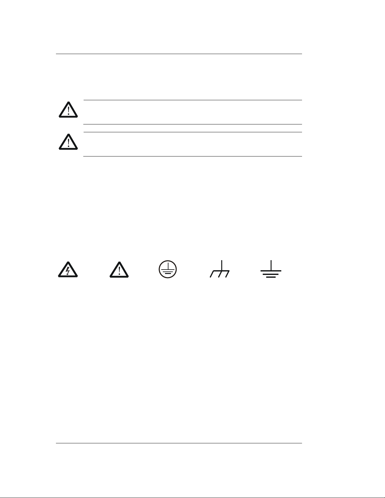
WARNING
Indicates a potentially hazardous situation or practice which, if not
avoided, will result in serious injury or death.
CAUTION
Indicates a potentially hazardous situation or practice which, if not
avoided, could result in damage to the product or loss of important data.
DANGER
It calls attention to an operation, if not correctly performed, could
result in injury or hazard immediately.
WARNING
It calls attention to an operation, if not correctly performed, could
result in potential injury or hazard.
CAUTION
It calls attention to an operation, if not correctly performed, could
result in damage to the product or other devices connected to the
product.
Hazardous
Voltage
Safety
Warning
Protective
Earth
Terminal
Chassis
Ground
Test
Ground
Safety Notices and Symbols
Safety Notices in this Manual:
Safety Terms on the Product:
Safety Symbols on the Product:
IV DS1000Z-E User Guide
Find Quality Products Online at: [email protected]
www.GlobalTestSupply.com
Page 6
RIGOL
WARNING
This oscilloscope can only be used for measurements within its specified
measurement categories.
Measurement Category
Measurement Category
DS1000Z-E series digital oscilloscopes can make measurements in Measurement
Category I.
Measurement Category Definitions
Measurement category I is for measurements performed on circuits not directly
connected to MAINS. Examples are measurements on circuits not derived from
MAINS, and specially protected (internal) MAINS derived circuits. In the latter case,
transient stresses are variable. For that reason, the transient withstand capability of
the equipment is made known to the user.
Measurement category II is for measurements performed on circuits directly
connected to low voltage installations. Examples are measurements on household
appliances, portable tools and similar equipment.
Measurement category III is for measurements performed in building installations.
Examples are measurements on distribution boards, circuit-breakers, wiring
(including cables, bus-bars, junction boxes, switches and socket-outlets) in fixed
installations, equipment for industrial use and some other equipment. For example,
stationary motors with permanent connection to a fixed installation.
Measurement category IV is for measurements performed at the source of a
low-voltage installation. Examples are electricity meters and measurements on
primary overcurrent protection devices and ripple control units.
DS1000Z-E User Guide V
Find Quality Products Online at: [email protected]
www.GlobalTestSupply.com
Page 7
RIGOL
WARNING
Inadequate ventilation may cause a temperature increase which can
damage the instrument. So please keep the instrument well ventilated
during operation and inspect the intake and fan regularly.
Ventilation Requirement
This oscilloscope uses fan to force cooling. Please make sure that the air intake and
exhaust areas are free from obstructions and have free air. When using the
oscilloscope in a bench-top or rack setting, provide at least 10 cm clearance beside,
above and behind the instrument for adequate ventilation.
VI DS1000Z-E User Guide
Find Quality Products Online at: [email protected]
www.GlobalTestSupply.com
Page 8
RIGOL
WARNING
To avoid short circuits inside the instrument or electric shocks, please do
not operate in humid environment.
WARNING
Make sure that no overvoltage (such as that produced by a
thunderstorm) can reach the product, or else the operator might be
exposed to the danger of electric shock.
Working Environment
Temperature
Operating: 0℃ to +50℃
Non-operating: -40℃ to +70℃
Humidity
0℃ to +30℃: ≤95% relative humidity
+30℃ to +40℃: ≤75% relative humidity
+40℃ to +50℃: ≤45% relative humidity
Altitude
Operating: below 3 km
Non-operating: below 15 km
Installation (Overvoltage) Category
This product is powered by mains conforming to installation (overvoltage) category
II.
Installation (Overvoltage) Category Definitions
Installation (overvoltage) category I refers to signal level which is applicable to
equipment measurement terminals connected to the source circuit. In these
terminals, precautions are done to limit the transient voltage to the corresponding
low level.
Installation (overvoltage) category II refers to the local power distribution level
which is applicable to equipment connected to the AC line (AC power).
Pollution Degree
Degree 2
Pollution Degree Definitions
Pollution degree 1: No pollution or only dry, non-conductive pollution occurs. The
pollution has no influence. For example, a clean room or air-conditioned office
environment.
DS1000Z-E User Guide VII
Find Quality Products Online at: [email protected]
www.GlobalTestSupply.com
Page 9
RIGOL
Pollution degree 2: Normally only dry, non-conductive pollution occurs. Occasionally
a temporary conductivity caused by condensation may occur. For example, general
indoor environment.
Pollution degree 3: Conductive pollution occurs, or dry, non-conductive pollution
occurs which becomes conductive due to condensation which is expected. For
example, sheltered outdoor environment.
Pollution degree 4: Pollution that generates persistent conductivity through
conductive dust, rain, or snow. For example, outdoor locations.
Safety Class
Class 1 – Grounded Product
VIII DS1000Z-E User Guide
Find Quality Products Online at: [email protected]
www.GlobalTestSupply.com
Page 10
RIGOL
CAUTION
To avoid damage to the instrument, do not expose it to caustic liquids.
WARNING
To avoid short-circuit resulting from moisture or personal injuries, ensure
that the instrument is completely dry before connecting it to the power
supply.
Care and Cleaning
Care
Do not store or leave the instrument where it may be exposed to direct sunlight for
long periods of time.
Cleaning
Clean the instrument regularly according to its operating conditions.
1. Disconnect the instrument from all power sources.
2. Clean the external surfaces of the instrument with a soft cloth dampened with
mild detergent or water. Avoid having any water or other objects into the
chassis via the heat dissipation hole. When cleaning the LCD, take care to avoid
scarifying it.
Environmental Considerations
The following symbol indicates that this product complies with the WEEE Directive
2002/96/EC.
Product End-of-Life Handling
The equipment may contain substances that could be harmful to the environment or
human health. To avoid the release of such substances into the environment and
avoid harm to human health, we recommend you to recycle this product
appropriately to ensure that most materials are reused or recycled properly. Please
contact your local authorities for disposal or recycling information.
DS1000Z-E User Guide IX
Find Quality Products Online at: [email protected]
www.GlobalTestSupply.com
Page 11
RIGOL
DS1000Z-E Series Overview
DS1000Z-E series is a multifunctional and high-performance digital oscilloscope
designed on the basis of the UltraVision technique developed by RIGOL. Featuring
extremely high memory depth, wide dynamic range, clear display, excellent
waveform capture rate and comprehensive triggering functions, it is a useful
commissioning instrument for various fields such as communication, aerospace,
defense, embedded systems, computers, research and education. Wherein, the
mixed signal digital oscilloscope aimed at the embedded design and test fields allows
users to measure analog and digital signals at the same time. DS1000Z-E is the one
with the most comprehensive functions and the most outstanding specifications
among the 200 MHz bandwidth digital oscilloscopes.
Main features:
1 GSa/s real-time sample rate of the analog channels; up to 24 Mpts standard
memory depth
2 analog channels, 200 MHz analog channel bandwidth
30,000 wfms/s (dots display) waveform capture rate
Real-time hardware waveform recording and playback functions; up to 60,000
frames of waveform can be recorded
Intensity graded color display
Low base noise, 1 mV/div to 10 V/div ultra-wide vertical dynamic range
7.0 inch WVGA (800*480) TFT LCD, with ultra-wide screen, vivid picture, low
power consumption and long service life
Adjustable waveform brightness
Auto setting of waveform display (AUTO)
Up to 15 kinds of trigger functions, including various protocol triggers
Standard parallel decoding and multiple serial decoding
Auto measurement of 37 waveform parameters (with statistics)
Fine delayed sweep function
Built-in FFT function
Multiple waveform math operation functions
Pass/fail test function
Standard interfaces: USB Device, USB Host, LAN and Aux
Conform to LXI CORE 2011 DEVICE class instrument standards; enable quick,
economic and efficient creation and reconfiguration of test system
Supports remote command control
Built-in help to facilitate information acquisition
Supports multiple languages and Chinese/English input
Novel and delicate industrial design and easy operation
X DS1000Z-E User Guide
Find Quality Products Online at: [email protected]
www.GlobalTestSupply.com
Page 12
RIGOL
Document Overview
Main Topics of this Manual:
Chapter 1 Quick Start
Introduce the preparations before using the oscilloscope and provide a basic
introduction of the instrument.
Chapter 2 To Set the Vertical System
Introduce the vertical system functions of the oscilloscope.
Chapter 3 To Set the Horizontal System
Introduce the horizontal system functions of the oscilloscope.
Chapter 4 To Set the Sample System
Introduce the sample system functions of the oscilloscope.
Chapter 5 To Trigger the Oscilloscope
Introduce the trigger mode, trigger coupling, trigger holdoff, external trigger and
various trigger types of the oscilloscope.
Chapter 6 MATH and Measurement
Introduce how to make math operation, auto measurement and cursor
measurement.
Chapter 7 Protocol Decoding
Introduce how to decode the input signal using those common protocols.
Chapter 8 Reference Waveform
Introduce how to compare the input waveform with the reference waveform.
Chapter 9 Pass/Fail Test
Introduce how to monitor the input signal using the Pass/Fail test.
Chapter 10 Waveform Record
Introduce how to analyze the input signal using waveform record.
Chapter 11 Display Control
Introduce how to control the display of the oscilloscope.
Chapter 12 Store and Recall
Introduce how to store and recall the measurement result and the setting of the
oscilloscope.
DS1000Z-E User Guide XI
Find Quality Products Online at: [email protected]
www.GlobalTestSupply.com
Page 13
RIGOL
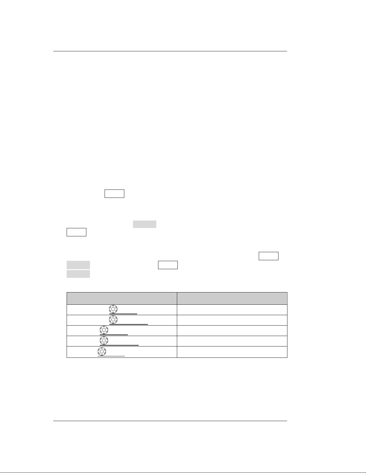
Label
Knob
HORIZONTAL SCALE
Horizontal Scale Knob
HORIZONTAL POSITION
Horizontal Position Knob
VERTICAL SCALE
Vertical Scale Knob
VERTICAL POSITION
Vertical Position Knob
TRIGGER LEVEL
Trigger Level Knob
Chapter 13 Accessibility Setting
Introduce how to set the remote interfaces and system-related functions.
Chapter 14 Remote Control
Introduce how to control the oscilloscope remotely.
Chapter 15 Troubleshooting
Introduce how to deal with the common failures of the oscilloscope.
Chapter 16 Appendix
Provide common information such as the options and accessories.
Format Conventions in this Manual:
1. Key
The front panel keys are denoted by the format of "Key Name (Bold) + Text Box".
For example, Utility denotes the "Utility" key.
2. Menu
The menu items are denoted by the format of "Menu Word (Bold) + Character
Shading". For example, System denotes the "System" menu item under
Utility.
3. Operation Step
The next step of operation is denoted by an arrow "". For example, Utility
System denotes that first press Utility on the front panel and then press
System.
4. Knob
Content Conventions in this Manual:
DS1000Z-E series includes the following models. Unless otherwise noted, this
manual takes DS1202Z-E for example to illustrate the functions and operation
methods of DS1000Z-E series.
XII DS1000Z-E User Guide
Find Quality Products Online at: [email protected]
www.GlobalTestSupply.com
Page 14
RIGOL
Model
Analog Bandwidth
Number of Analog Channels
DS1202Z-E
200 MHz
2
DS1000Z-E User Guide XIII
Find Quality Products Online at: [email protected]
www.GlobalTestSupply.com
Page 15
RIGOL Contents
Contents
Guaranty and Declaration ......................................................................... I
Safety Requirement ................................................................................. II
General Safety Summary........................................................................... II
Safety Notices and Symbols ..................................................................... IV
Measurement Category ............................................................................. V
Ventilation Requirement ........................................................................... VI
Working Environment ............................................................................. VII
Care and Cleaning ................................................................................... IX
Environmental Considerations ................................................................... IX
DS1000Z-E Series Overview .................................................................... X
Document Overview ............................................................................... XI
Chapter 1 Quick Start ........................................................................ 1-1
General Inspection ................................................................................. 1-2
Appearance and Dimensions ................................................................... 1-3
To Prepare the Oscilloscope for Use ......................................................... 1-4
To Adjust the Supporting Legs .......................................................... 1-4
To Connect to Power Supply ............................................................. 1-4
Turn-on Checkout ............................................................................ 1-5
To Connect the Probe ....................................................................... 1-5
Function Inspection ......................................................................... 1-6
Probe Compensation ........................................................................ 1-8
Front Panel Overview ............................................................................. 1-9
Rear Panel Overview ............................................................................ 1-10
Front Panel Function Overview .............................................................. 1-12
VERTICAL ..................................................................................... 1-12
HORIZONTAL ................................................................................ 1-13
TRIGGER ...................................................................................... 1-14
CLEAR .......................................................................................... 1-14
AUTO ........................................................................................... 1-14
RUN/STOP .................................................................................... 1-15
SINGLE ......................................................................................... 1-15
Multifunction Knob ......................................................................... 1-15
Function Menus ............................................................................. 1-16
Print ............................................................................................. 1-17
User Interface ...................................................................................... 1-18
Parameter Setting Method ..................................................................... 1-21
To Use the Security Lock ....................................................................... 1-22
To Use the Built-in Help System ............................................................. 1-23
Chapter 2 To Set the Vertical System ................................................. 2-1
To Enable the Analog Channel ................................................................. 2-2
XIV DS1000Z-E User Guide
Find Quality Products Online at: [email protected]
www.GlobalTestSupply.com
Page 16

Contents RIGOL
Channel Coupling .................................................................................. 2-2
Bandwidth Limit .................................................................................... 2-3
Probe Ratio ........................................................................................... 2-3
Waveform Invert ................................................................................... 2-4
Vertical Scale ........................................................................................ 2-4
Amplitude Unit ...................................................................................... 2-5
Channel Label ....................................................................................... 2-5
Delay Calibration of the Analog Channel .................................................. 2-7
Chapter 3 To Set the Horizontal System ............................................. 3-1
Delayed Sweep ..................................................................................... 3-2
Time Base Mode.................................................................................... 3-3
YT Mode ........................................................................................ 3-3
XY Mode ........................................................................................ 3-3
Roll Mode ....................................................................................... 3-5
Chapter 4 To Set the Sample System .................................................. 4-1
Acquisition Mode ................................................................................... 4-2
Normal .......................................................................................... 4-2
Peak Detect .................................................................................... 4-2
Average ......................................................................................... 4-2
High Resolution .............................................................................. 4-3
Sin(x)/x ................................................................................................ 4-4
Sample Rate ......................................................................................... 4-4
Memory Depth ...................................................................................... 4-6
Anti-aliasing .......................................................................................... 4-7
Chapter 5 To Trigger the Oscilloscope ................................................ 5-1
Trigger Source ...................................................................................... 5-2
Trigger Mode ........................................................................................ 5-3
Trigger Coupling .................................................................................... 5-4
Trigger Holdoff ...................................................................................... 5-5
Noise Rejection ..................................................................................... 5-5
Trigger Type ......................................................................................... 5-6
Edge Trigger ................................................................................... 5-7
Pulse Trigger .................................................................................. 5-8
Slope Trigger ................................................................................. 5-10
Video Trigger ................................................................................. 5-13
Pattern Trigger .............................................................................. 5-15
Duration Trigger ............................................................................ 5-17
TimeOut Trigger ............................................................................ 5-19
Runt Trigger .................................................................................. 5-21
Window Trigger ............................................................................. 5-23
Delay Trigger ................................................................................. 5-25
Setup/Hold Trigger ......................................................................... 5-28
Nth Edge Trigger............................................................................ 5-30
RS232 Trigger ................................................................................ 5-32
DS1000Z-E User Guide XV
Find Quality Products Online at: [email protected]
www.GlobalTestSupply.com
Page 17
RIGOL Contents
I2C Trigger.................................................................................... 5-34
SPI Trigger .................................................................................... 5-37
Trigger Output Connector...................................................................... 5-39
Chapter 6 MATH and Measurement .................................................... 6-1
Math Operation ...................................................................................... 6-2
Addition .......................................................................................... 6-2
Subtraction ..................................................................................... 6-3
Multiplication ................................................................................... 6-4
Division .......................................................................................... 6-4
FFT ................................................................................................ 6-6
"AND" Operation ........................................................................... 6-11
"OR" Operation ............................................................................. 6-12
"XOR" Operation ............................................................................ 6-13
"NOT" Operation............................................................................ 6-14
Intg.............................................................................................. 6-15
Diff .............................................................................................. 6-16
Sqrt .............................................................................................. 6-17
Lg (Use 10 as the Base) ................................................................. 6-17
Ln ................................................................................................ 6-18
Exp .............................................................................................. 6-19
Abs .............................................................................................. 6-20
Filter ............................................................................................ 6-20
Fx Operation ................................................................................. 6-22
Math Operation Label ..................................................................... 6-22
Auto Measurement ............................................................................... 6-23
Quick Measurement after AUTO ...................................................... 6-23
One-key Measurement of 37 Parameters .......................................... 6-24
Frequency Counter Measurement .................................................... 6-30
Measurement Setting ..................................................................... 6-30
To Clear the Measurement .............................................................. 6-31
All Measurement ............................................................................ 6-33
Statistic Function ........................................................................... 6-33
Measurement History ..................................................................... 6-34
Measurement Result Display Type ................................................... 6-34
Cursor Measurement ............................................................................ 6-35
Manual Mode ................................................................................ 6-35
Track Mode ................................................................................... 6-38
Auto Mode .................................................................................... 6-40
XY Mode ....................................................................................... 6-41
Chapter 7 Protocol Decoding ............................................................. 7-1
Parallel Decoding ................................................................................... 7-2
RS232 Decoding .................................................................................... 7-6
I2C Decoding ....................................................................................... 7-11
SPI Decoding ....................................................................................... 7-14
XVI DS1000Z-E User Guide
Find Quality Products Online at: [email protected]
www.GlobalTestSupply.com
Page 18
Contents RIGOL
Chapter 8 Reference Waveform .......................................................... 8-1
To Enable REF Function.......................................................................... 8-2
To Select REF Source ............................................................................. 8-2
To Adjust REF Waveform Display ............................................................. 8-2
To Save to Internal Memory ................................................................... 8-2
To Set the Color .................................................................................... 8-3
To Reset the Reference Waveform ........................................................... 8-3
To Export to Internal or External Memory ................................................ 8-3
To Import from Internal or External Memory ............................................ 8-3
Chapter 9 Pass/Fail Test ..................................................................... 9-1
To Enable Pass/Fail Test ......................................................................... 9-2
To Select Source.................................................................................... 9-2
Mask Range .......................................................................................... 9-2
Test and Output .................................................................................... 9-3
To Save the Test Mask ........................................................................... 9-4
To Load the Test Mask ........................................................................... 9-4
Chapter 10 Waveform Record ...................................................... 10-1
Common Settings ................................................................................. 10-2
Playback Option ................................................................................... 10-3
Record Option ...................................................................................... 10-4
Chapter 11 Display Control .......................................................... 11-1
To Select the Display Type ..................................................................... 11-2
To Set the Persistence Time .................................................................. 11-2
To Set the Waveform Intensity ............................................................... 11-3
To Set the Screen Grid .......................................................................... 11-3
To Set the Grid Brightness ..................................................................... 11-3
Chapter 12 Store and Recall ......................................................... 12-1
Storage System .................................................................................... 12-2
Storage Type ....................................................................................... 12-2
Internal Storage and Recall ................................................................... 12-5
External Storage and Recall ................................................................... 12-6
Disk Management ................................................................................. 12-7
To Select File Type ......................................................................... 12-7
To Create a New File or Folder ........................................................ 12-8
To Delete a File or Folder .............................................................. 12-11
To Rename a File or Folder ........................................................... 12-11
To Clear the Local Memory ............................................................ 12-11
Factory .............................................................................................. 12-12
Chapter 13 Accessibility Setting ................................................... 13-1
Remote Interface Configuration ............................................................. 13-2
LAN Configuration .......................................................................... 13-2
USB Device ................................................................................... 13-5
System-related ..................................................................................... 13-6
DS1000Z-E User Guide XVII
Find Quality Products Online at: [email protected]
www.GlobalTestSupply.com
Page 19
RIGOL Contents
Sound .......................................................................................... 13-6
Language ..................................................................................... 13-6
System Information ....................................................................... 13-6
Vertical Reference .......................................................................... 13-6
Power-off Recall ............................................................................ 13-7
Self-calibration .............................................................................. 13-7
Print Setting .................................................................................. 13-8
Aux Output ................................................................................. 13-10
Option Management .................................................................... 13-11
Auto Options ............................................................................... 13-12
Key Lock ..................................................................................... 13-12
Chapter 14 Remote Control ......................................................... 14-1
Remote Control via USB ........................................................................ 14-2
Remote Control via LAN ........................................................................ 14-6
Chapter 15 Troubleshooting ........................................................ 15-1
Chapter 16 Appendix ................................................................... 16-1
Appendix A: Accessories and Options ..................................................... 16-1
Appendix B: Warranty ........................................................................... 16-2
Index ........................................................................................................ 1
XVIII DS1000Z-E User Guide
Find Quality Products Online at: [email protected]
www.GlobalTestSupply.com
Page 20
Chapter 1 Quick Start RIGOL
Chapter 1 Quick Start
This chapter introduces the precautions when using the oscilloscope for the first time,
the front/rear panels of the oscilloscope, the user interface and the using method of
the built-in help system.
The contents of this chapter:
General Inspection
Appearance and Dimensions
To Prepare the Oscilloscope for Use
Front Panel Overview
Rear Panel Overview
Front Panel Function Overview
User Interface
Parameter Setting Method
To Use the Security Lock
To Use the Built-in Help System
DS1000Z-E User Guide 1-1
Find Quality Products Online at: [email protected]
www.GlobalTestSupply.com
Page 21
RIGOL Chapter 1 Quick Start
General Inspection
1. Inspect the packaging
If the packaging has been damaged, do not dispose the damaged packaging or
cushioning materials until the shipment has been checked for completeness and
has passed both electrical and mechanical tests.
The consigner or carrier shall be liable for the damage to the instrument
resulting from shipment. RIGOL would not be responsible for free
maintenance/rework or replacement of the instrument.
2. Inspect the instrument
In case of any mechanical damage, missing parts, or failure in passing the
electrical and mechanical tests,
3. Check the accessories
Please check the accessories according to the packing lists. If the accessories
are damaged or incomplete,
1-2 DS1000Z-E User Guide
Find Quality Products Online at: [email protected]
www.GlobalTestSupply.com
Page 22
Chapter 1 Quick Start RIGOL
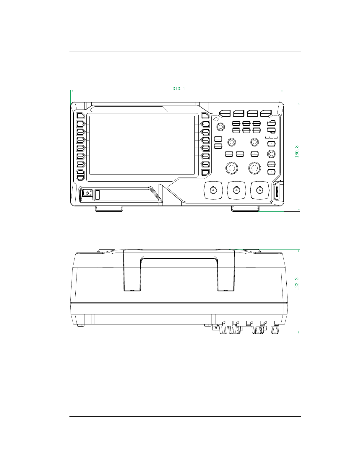
Appearance and Dimensions
Figure 1-1 Front View Unit: mm
Figure 1-2 Top View Unit: mm
DS1000Z-E User Guide 1-3
Find Quality Products Online at: [email protected]
www.GlobalTestSupply.com
Page 23
RIGOL Chapter 1 Quick Start
Power Cord Connector
To Prepare the Oscilloscope for Use
To Adjust the Supporting Legs
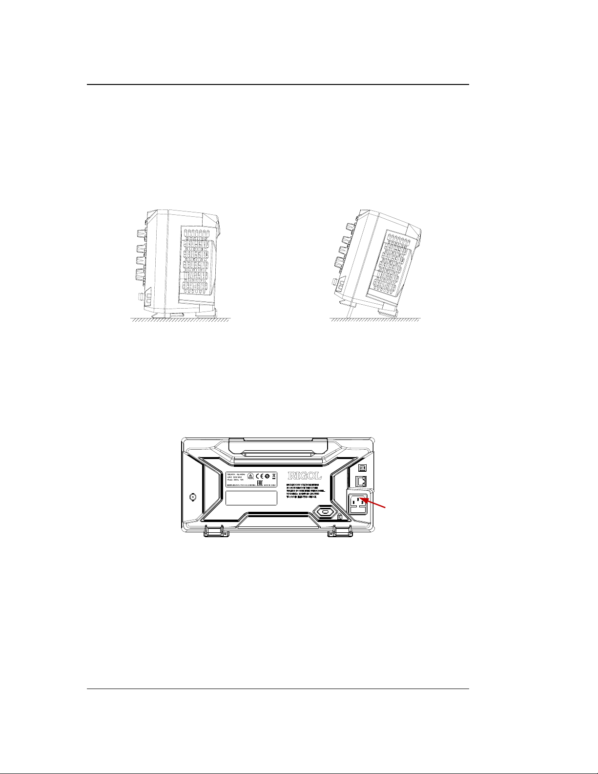
Adjust the supporting legs properly to use them as stands to tilt the oscilloscope
upwards for stable placement of the oscilloscope as well as better operation and
observation.
Figure 1-3 To Adjust the Supporting Legs
To Connect to Power Supply
The power requirements of the oscilloscope are 100-240 V, 45-440 Hz. Please use
the power cord supplied with the accessories to connect the oscilloscope to the AC
power source as shown in the figure below.
Figure 1-4 To Connect to Power Supply
1-4 DS1000Z-E User Guide
Find Quality Products Online at: [email protected]
www.GlobalTestSupply.com
Page 24
Chapter 1 Quick Start RIGOL
Turn-on Checkout
When the oscilloscope is connected to power, press the Power key at the
lower-left corner of the front panel to start the oscilloscope. During the start-up
process, the oscilloscope performs a series of self-tests. After the self-test, the
welcome screen is displayed. The instrument is installed with the trial versions of the
options before leaving factory and the remaining trial time is about 2,000 minutes.
The "Installed Options" dialog box will be displayed if your instrument has currently
installed the trial versions of options. From this dialog box you can view the name,
detail, version and remaining trial time of the option currently installed.
To Connect the Probe
RIGOL provides passive probe for DS1000Z-E series. For the model of the probes,
please refer to
probes, please refer to the corresponding Probe User Guide.
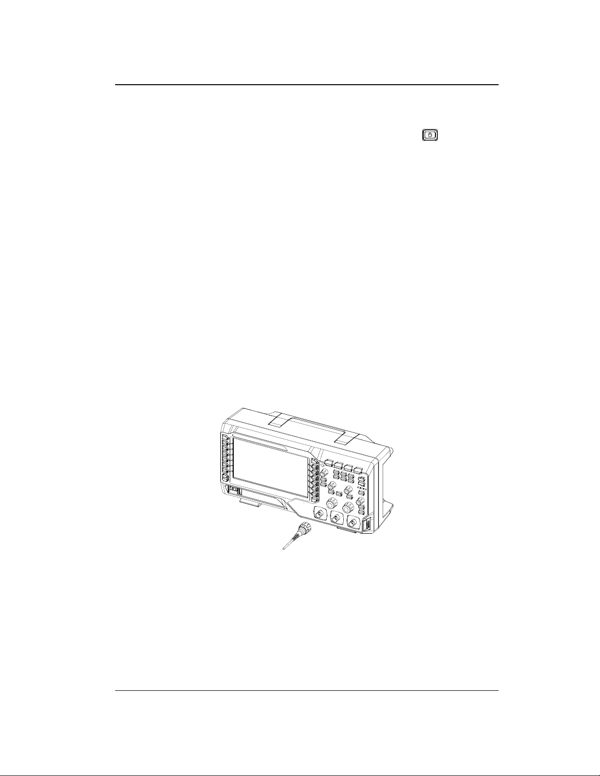
Connect the passive probe:
1. Connect the BNC terminal of the probe to an analog channel input terminal of
the oscilloscope on the front panel.
2. Connect the ground alligator clip or spring of the probe to the circuit ground
terminal and connect the probe tip to the circuit point to be tested.
DS1000Z-E Series Datasheet
. For detailed technical information of the
Figure 1-5 To Connect the Passive Probe
After you connect the passive probe, check the probe function and probe
compensation adjustment before making measurements. For detailed procedures,
refer to "Function Inspection" and "Probe Compensation" sections in this
manual.
DS1000Z-E User Guide 1-5
Find Quality Products Online at: [email protected]
www.GlobalTestSupply.com
Page 25
RIGOL Chapter 1 Quick Start
WARNING
To avoid electric shock when using the probe, please make sure that the
insulated wire of the probe is in good condition. Do not touch the metallic
part of the probe when the probe is connected to high voltage source.
Compensation Signal Output Terminal
Ground Terminal
Function Inspection
1. Press Storage Default to restore the oscilloscope to its default
configuration.
2. Connect the ground alligator clip of the probe to the "Ground Terminal" as
shown in the figure below.
3. Use the probe to connect the input terminal of CH1 of the oscilloscope and the
"Compensation Signal Output Terminal" of the probe.
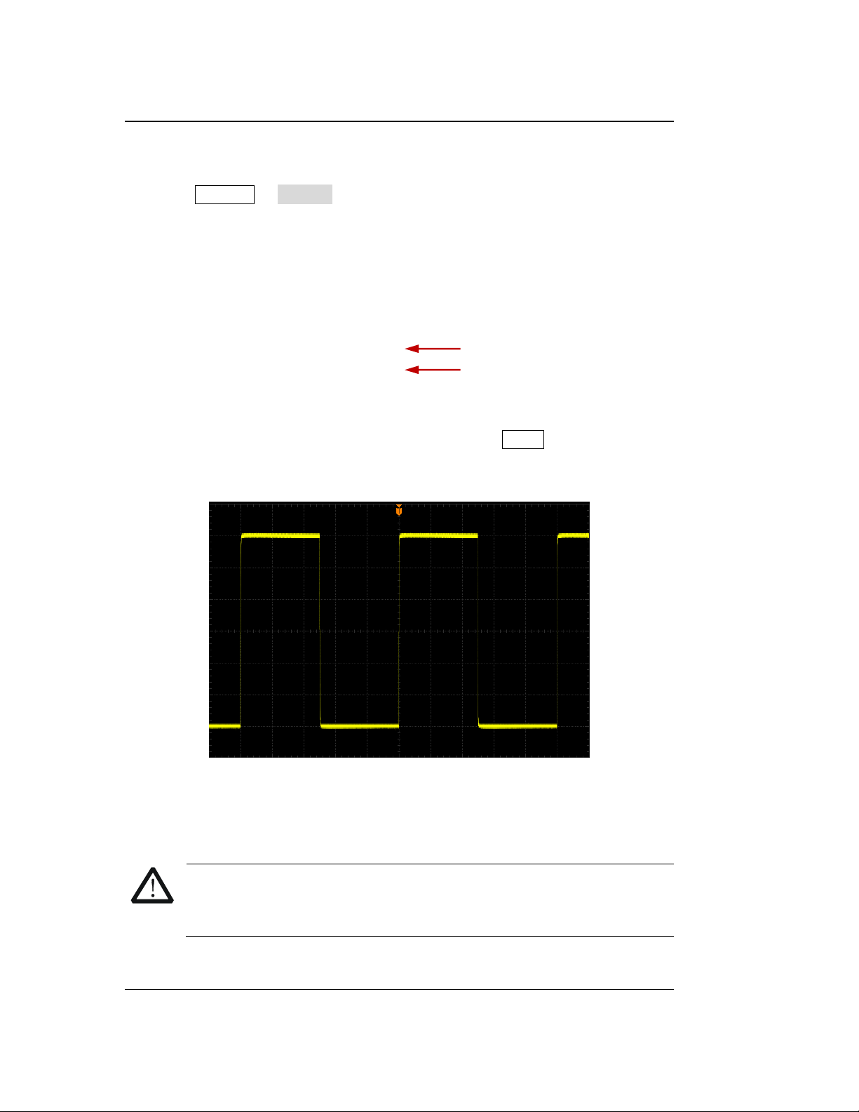
Figure 1-6 To Use the Compensation Signal
4. Set the attenuation on the probe to 10X. Then press AUTO.
5. Observe the waveform on the display. In normal condition, the square waveform
as shown in the figure below should be displayed.
Figure 1-7 Square Waveform
6. Use the same method to test the other channels. If the square waveforms
actually shown do not match that in the figure above, please perform "Probe
Compensation".
1-6 DS1000Z-E User Guide
Find Quality Products Online at: [email protected]
www.GlobalTestSupply.com
Page 26
Chapter 1 Quick Start RIGOL
Tip
The signal output from the probe compensation connector can only be used for
probe compensation adjustment and cannot be used for calibration.
DS1000Z-E User Guide 1-7
Find Quality Products Online at: [email protected]
www.GlobalTestSupply.com
Page 27
RIGOL Chapter 1 Quick Start
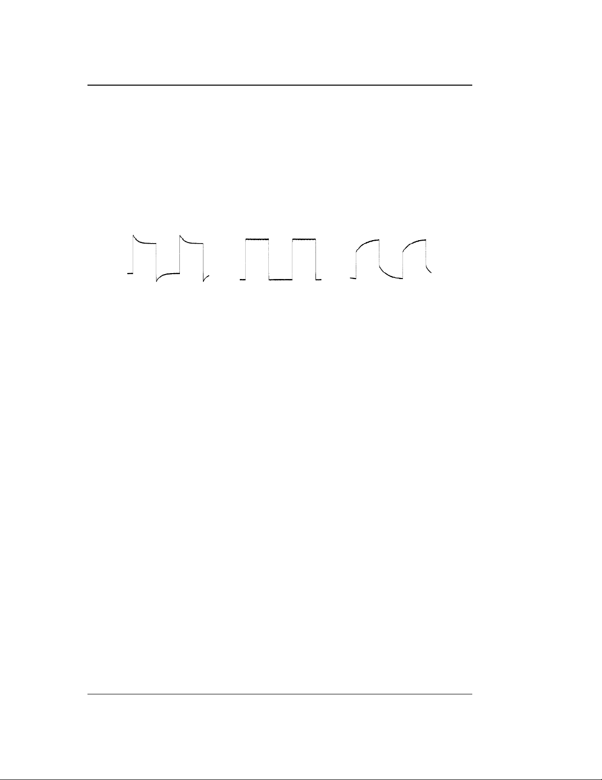
Over compensated Perfectly compensated Under compensated
Probe Compensation
When the probes are used for the first time, you should compensate the probes to
make them match the input channels of the oscilloscope. Non-compensated or
poorly compensated probes may cause measurement inaccuracy or errors. The
probe compensation procedures are as follows.
1. Perform Step 1, 2, 3 and 4 specified in "Function Inspection".
2. Check the displayed waveforms and compare them with the following figures.
Figure 1-8 Probe Compensation
3. Use a nonmetallic driver to adjust the low-frequency compensation adjustment
hole on the probe until the displayed waveform is displayed as "Perfectly
compensated" in the figure above.
1-8 DS1000Z-E User Guide
Find Quality Products Online at: [email protected]
www.GlobalTestSupply.com
Page 28
Chapter 1 Quick Start RIGOL
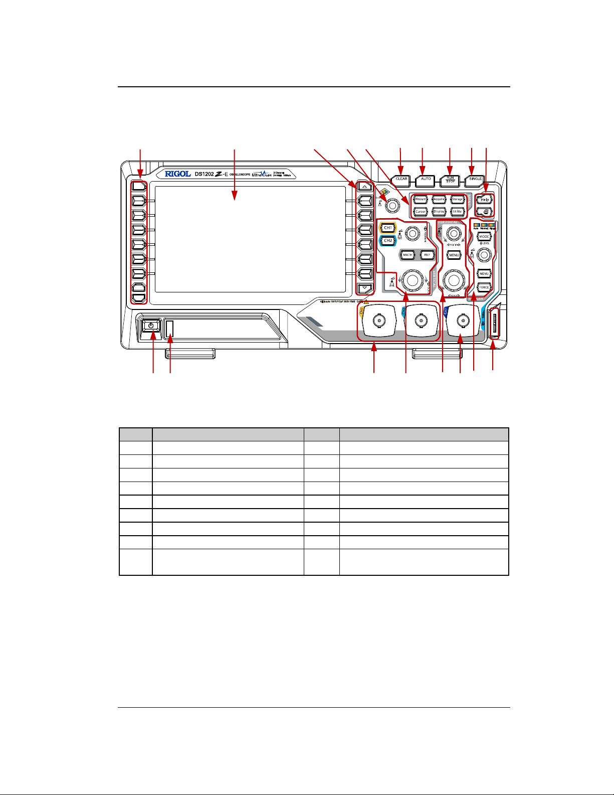
No.
Description
No.
Description
1
Measurement Menu Softkeys
10
Help/Print
2
LCD
11
Power Key
3
Function Menu Softkeys
12
USB Host Interface
4
Multifunction Knob
13
Analog Channel Input Area
5
Common Operation Keys
14
VERTICAL Control Area
6
CLEAR
15
HORIZONTAL Control Area
7
AUTO
16
External Trigger Input
8
RUN/STOP
17
TRIGGER Control Area
9
SINGLE
18
Probe Compensation Signal
Output Terminal/Ground Terminal
3 4 5 6 7 8 9 10
1 2
11 12 13 14 15 16 17 18
Front Panel Overview
Figure 1-9 Front Panel Overview
Table 1-1 Front Panel Descriptions
DS1000Z-E User Guide 1-9
Find Quality Products Online at: [email protected]
www.GlobalTestSupply.com
Page 29
RIGOL Chapter 1 Quick Start
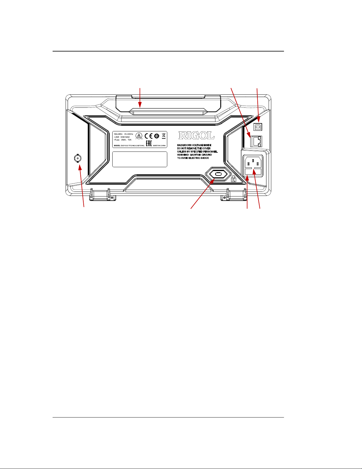
1 2 3
4 5 6 7
Rear Panel Overview
Figure 1-10 Rear Panel Overview
1. Handle
Pull up the handle vertically for easy carry of the instrument. When you do not
need the handle, press it down.
2. LAN
Connect the instrument to network via this interface for remote control. This
oscilloscope conforms to the LXI CORE 2011 DEVICE class instrument standards
and can quickly build test system with other instruments.
3. USB Device
You can connect the oscilloscope to a PictBridge printer or PC via this interface.
When a PC is connected, users can send SCPI commands using the PC software
or control the oscilloscope via user-defined programming. When a printer is
connected, users can print the waveform displayed on the screen using the
printer.
4. Trigger Out and Pass/Fail
Trigger Out:
The oscilloscope can output a signal that can reflect the current capture
rate of the oscilloscope at each trigger via this interface. Connect the signal
to a waveform display device and measure the frequency of the signal. The
measurement result is the same with the current capture rate.
1-10 DS1000Z-E User Guide
Find Quality Products Online at: [email protected]
www.GlobalTestSupply.com
Page 30
Chapter 1 Quick Start RIGOL
Pass/Fail:
The instrument can output a negative pulse via this connector when a failed
waveform is detected during the pass/fail test. The instrument continuously
outputs a low level via this connector when no failed waveform is detected.
5. Lock Hole
You can lock the instrument to a fixed location by using the security lock (please
purchase it yourself) via the lock hole.
6. Fuse
If a new fuse is required, please use the specified fuse (250V, T2A). The
replacing method is as follows.
a) Turn off the instrument, switch off the power supply and remove the power
cord.
b) Insert a small straight screwdriver into the slot at the power cord connector
and pry out the fuse holder gently.
c) Take out the fuse and replace it with a specified fuse. Then, install the fuse
holder.
7. AC Power Cord Connector
AC power input terminal. The power requirements of this oscilloscope are
100-240 V, 45-440 Hz. Use the power cord provided with the accessories to
connect the instrument to AC power. Then, you can press the Power key on the
front panel to start the instrument.
DS1000Z-E User Guide 1-11
Find Quality Products Online at: [email protected]
www.GlobalTestSupply.com
Page 31
RIGOL Chapter 1 Quick Start
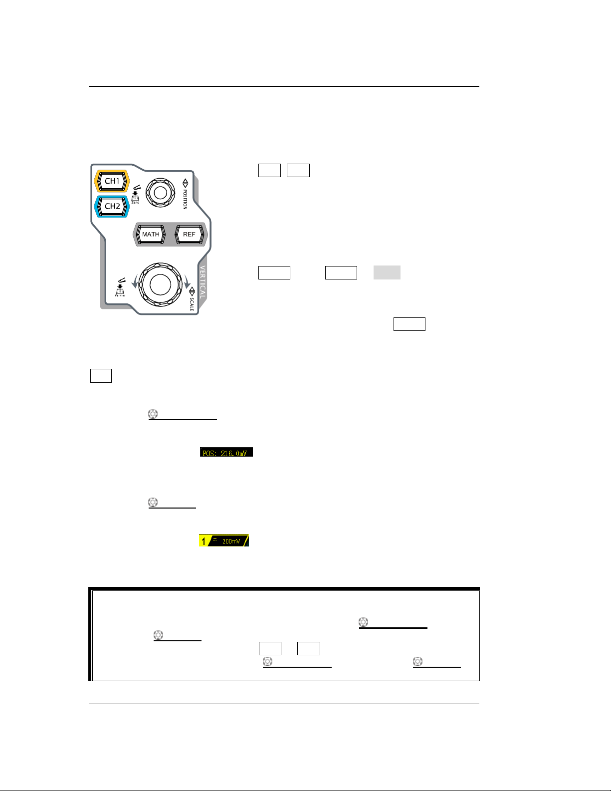
CH1, CH2: analog channel setting keys. The 2
channels are marked by different colors which
are also used to mark both the corresponding
waveforms on the screen and the channel
input connectors. Press any key to open the
corresponding channel menu and press again
to turn off the channel.
MATH: press MATH Math to open the
math operation menu under which A+B, A-B,
A× B, A/B, FFT, A&&B, A||B, A^B, !A, Intg, Diff,
Sqrt, Lg, Ln, Exp, Abs and Filter operations are
provided. You can also press MATH to open
the decoding menu and set the decoding
options.
REF: press this key to enable the reference waveform function to compare the
waveform actually measured with the reference waveform.
VERTICAL POSITION: modify the vertical position of the current channel
waveform. Turn clockwise to increase the position and turn counterclockwise to
decrease. During the modification, the waveform would move up and down and the
position message (e.g. ) at the lower-left corner of the screen would
change accordingly. Press down this knob to quickly reset the vertical position to
zero.
VERTICAL SCALE: modify the vertical scale of the current channel. Turn
clockwise to decrease the scale and turn counterclockwise to increase. During the
modification, the display amplitude of the waveform would enlarge or reduce. The
scale information (e.g. ) at the lower side of the screen would change
accordingly. Press down this knob to quickly switch the vertical scale adjustment
mode between "Coarse" and "Fine".
Tip
How to set the vertical scale and vertical position of each channel?
The 2 channels of DS1000Z-E use the same VERTICAL POSITION and
VERTICAL SCALE knobs. If you want to set the vertical scale and vertical
position of a channel, please press CH1 or CH2 at first to select the desired
channel. Then turn the VERTICAL POSITION and VERTICAL SCALE
knobs to set the values.
Front Panel Function Overview
VERTICAL
Find Quality Products Online at: [email protected]
1-12 DS1000Z-E User Guide
www.GlobalTestSupply.com
Page 32
Chapter 1 Quick Start RIGOL
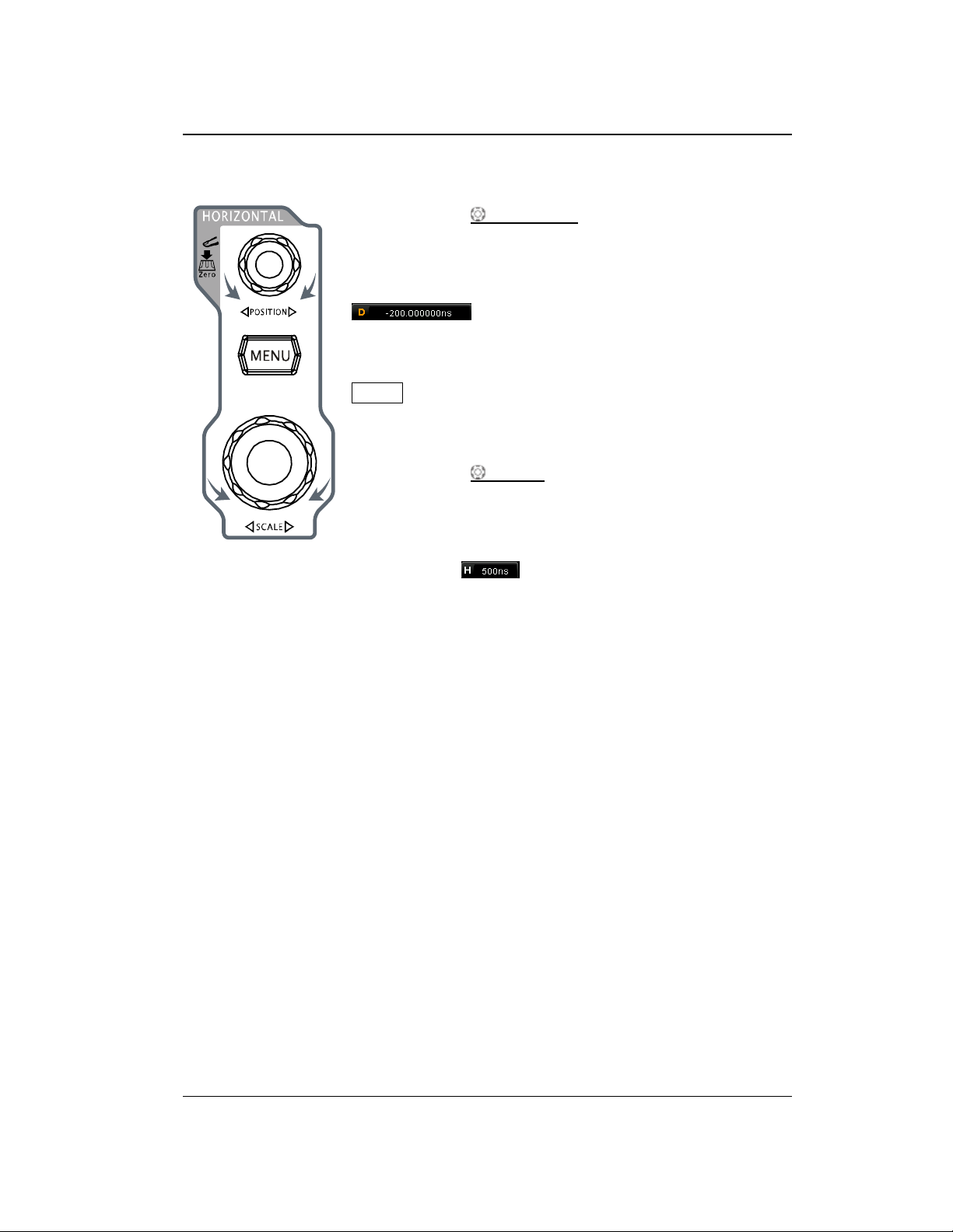
HORIZONTAL POSITION: modify the horizontal
position. The trigger point would move left or right relative
to the center of the screen when you rotate the knob. During
the modification, waveforms of all the channels would move
left or right and the horizontal position message (e.g.
) at the upper-right corner of the screen
would change accordingly. Press down this knob to quickly
reset the horizontal position (or the delayed sweep position).
MENU: press this key to open the horizontal control menu
where you can turn on or off the delayed sweep function and
switch between different time base modes.
HORIZONTAL SCALE: modify the horizontal time
base. Turn clockwise to reduce the time base and turn
counterclockwise to increase the time base. During the
modification, waveforms of all the channels will be displayed
in expanded or compressed mode and the time base
message (e.g. ) at the upper side of the screen
would change accordingly. Press down this knob to quickly
switch to the delayed sweep state.
HORIZONTAL
Find Quality Products Online at: [email protected]
DS1000Z-E User Guide 1-13
www.GlobalTestSupply.com
Page 33
RIGOL Chapter 1 Quick Start
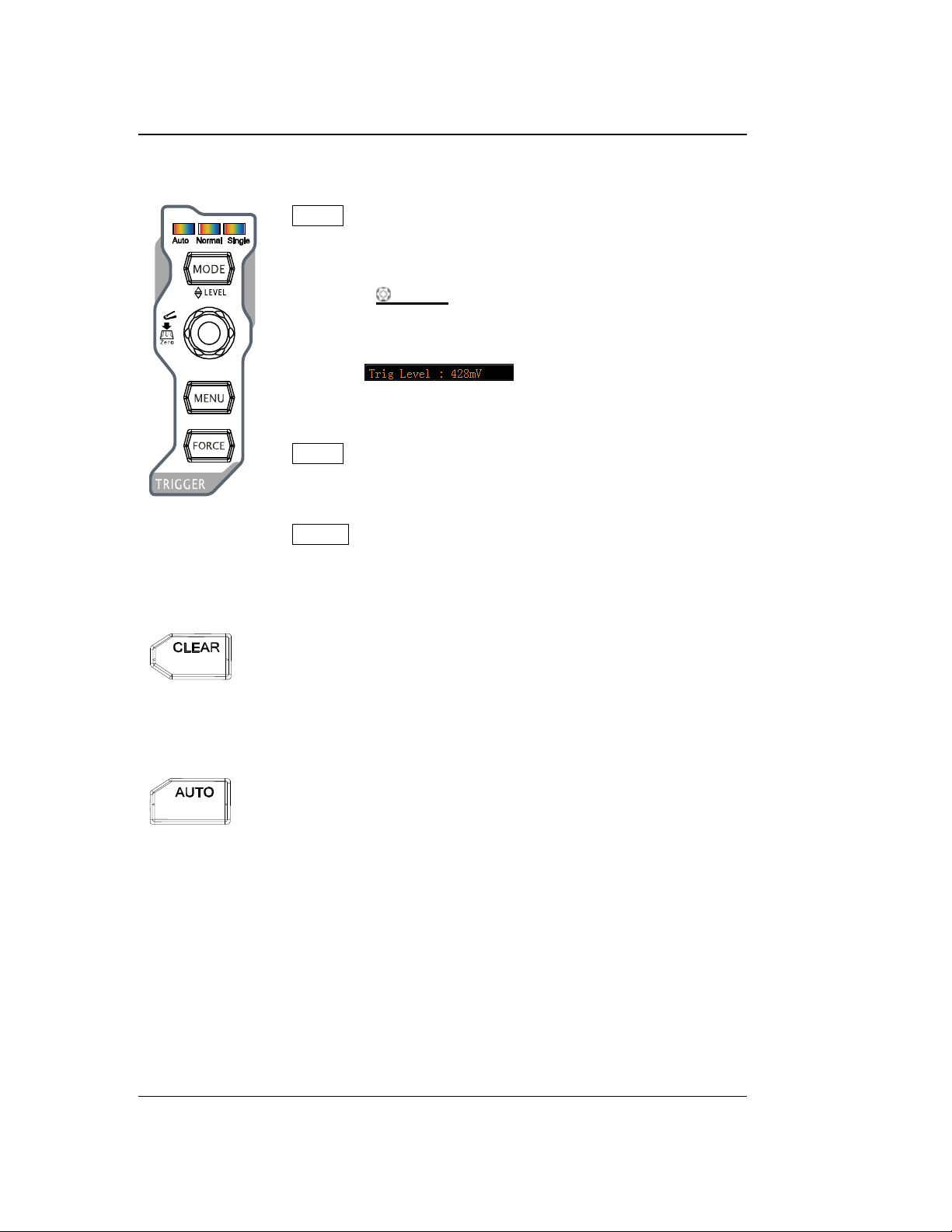
MODE: press this key to switch the trigger mode to Auto,
Normal or Single and the corresponding state backlight of
the current trigger mode would be illuminated.
TRIGGER LEVEL: modify the trigger level. Turn clockwise
to increase the level and turn counterclockwise to reduce the
level. During the modification, the trigger level line would
move up and down and the value in the trigger level message
box (e.g. ) at the lower-left corner of the
screen would change accordingly. Press down the knob to
quickly reset the trigger level to zero point.
MENU: press this key to open the trigger operation menu.
This oscilloscope provides various trigger types. For more
details, please refer to "To Trigger the Oscilloscope".
FORCE: press this key to generate a trigger signal forcibly.
Press this key to clear all the waveforms on the screen. If the
oscilloscope is in the "RUN" state, new waveforms will be
displayed.
Press this key to enable the waveform auto setting function. The
oscilloscope will automatically adjust the vertical scale,
horizontal time base and trigger mode according to the input
signal to realize optimum waveform display.
TRIGGER
CLEAR
AUTO
Note: Waveform auto setting function requires that the frequency of sine is no lower
Find Quality Products Online at: [email protected]
than 41 Hz; the duty cycle should be greater than 1% and the amplitude must be at
least 20 mVpp for square. Otherwise, the Waveform auto setting function may be
invalid and the quick parameter measurement function displayed in the menu will
also be unavailable.
1-14 DS1000Z-E User Guide
www.GlobalTestSupply.com
Page 34
Chapter 1 Quick Start RIGOL
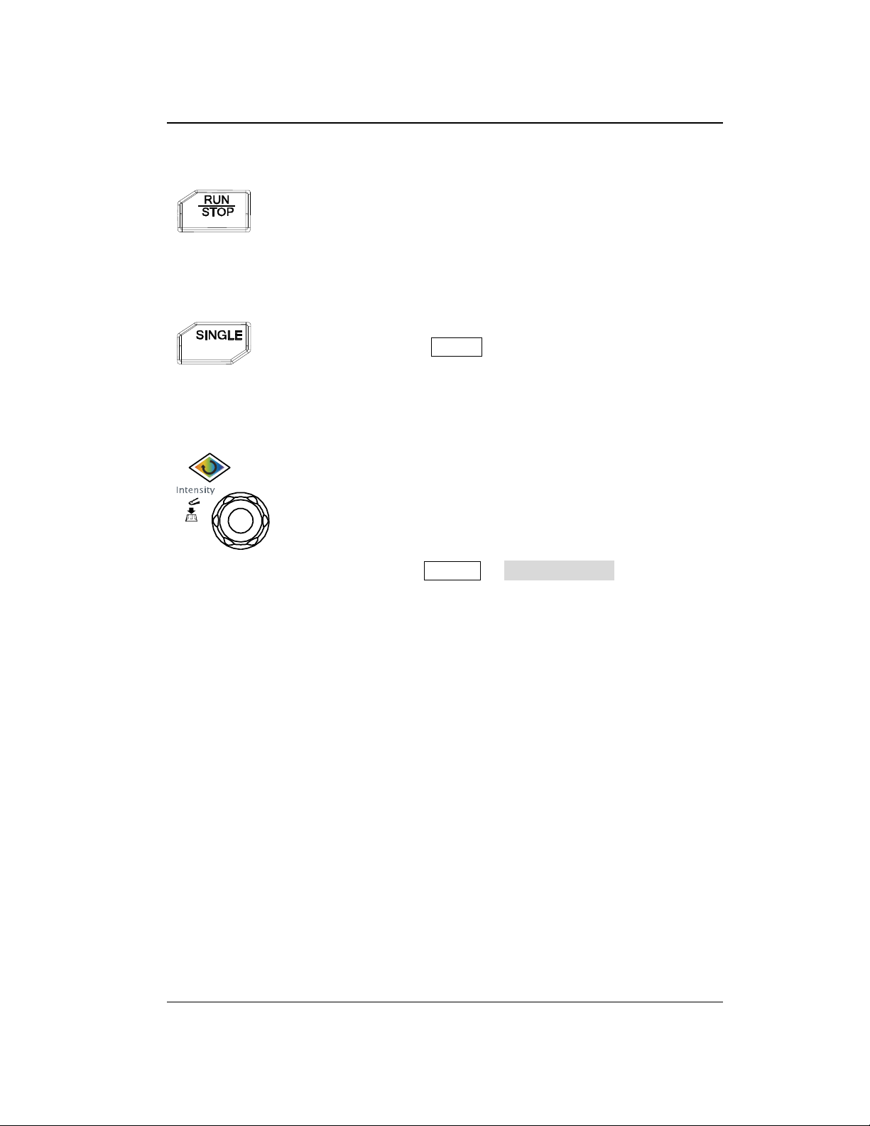
Press this key to "RUN" or "STOP" waveform sampling. In the
"RUN" state, the key is illuminated in yellow. In the "STOP"
state, the key is illuminated in red.
Press this key to set the trigger mode to "Single". In single
trigger mode, press FORCE to generate a trigger signal
immediately.
Adjust waveform brightness:
In non-menu-operation mode, turn this knob to adjust the
brightness of waveform display. The adjustable range is from
0% to 100%. Turn clockwise to increase the brightness and
counterclockwise to reduce. Press down this knob to reset the
brightness to 60%.
You can also press Display WaveIntensity and use the
knob to adjust the waveform brightness.
RUN/STOP
SINGLE
Multifunction Knob
Multifunctional:
In menu operation, the backlight of the knob goes on. Press any menu softkey and
rotate the knob to select the submenus under this menu and then press down the
knob to select the current submenu. It can also be used to modify parameters
(please refer to the introduction in "Parameter Setting Method") and input
filename.
Find Quality Products Online at: [email protected]
DS1000Z-E User Guide 1-15
www.GlobalTestSupply.com
Page 35
RIGOL Chapter 1 Quick Start
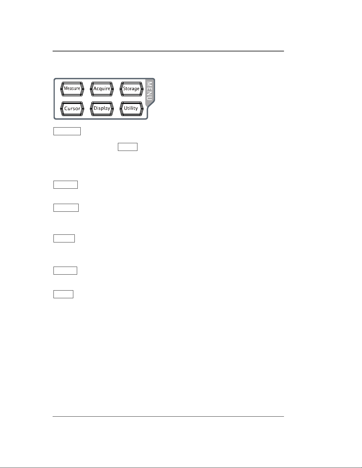
Function Menus
Measure: press this key to open the measurement setting menu. You can set the
measurement source, turn on or off the frequency counter, all measure, statistic
function and etc. Press MENU at the left of the screen to open the measurement
menus of 37 waveform parameters. Then, press down the corresponding menu
softkey to quickly realize one-key measurement and the measurement result will be
displayed at the bottom of the screen.
Acquire: press this key to enter the sample setting menu to set the acquisition
mode, Sin(x)/x and memory depth of the oscilloscope.
Storage: press this key to enter the file store and recall interface. The storable file
types include picture, traces, waves, setups, CSV and parameters. Internal and
external storage as well as disk management are also supported.
Cursor: press this key to enter the cursor measurement menu. The oscilloscope
provides four cursor modes: manual, track, auto and XY. Note that XY cursor mode is
only available when the horizontal time base is set to XY.
Display: press this key to enter the display setting menu to set the display type,
persistence time, wave intensity, grid type and grid brightness.
Utility: press this key to enter the system function setting menu to set the
system-related functions or parameters, such as the I/O, sound and language.
Besides, some advanced functions (such as the pass/fail test, waveform record, etc.)
are also supported.
1-16 DS1000Z-E User Guide
Find Quality Products Online at: [email protected]
www.GlobalTestSupply.com
Page 36
Chapter 1 Quick Start RIGOL
Press this key to print the screen or save the screen to a USB
storage device.
― If a PictBridge printer is connected currently and the printer is
in idle state, pressing this key will execute the print operation.
― If no printer is connected but a USB storage device is inserted,
pressing this key can save the screen to the USB storage
device in the specified format. For more details, please refer to
the introduction in "Storage Type".
― If both a printer and a USB storage device are connected at
the same time, the printer enjoys higher priority when
pressing this key.
Note: DS1000Z-E only supports the flash memory USB storage
device of FAT32 format.
Find Quality Products Online at: [email protected]
DS1000Z-E User Guide 1-17
www.GlobalTestSupply.com
Page 37
RIGOL Chapter 1 Quick Start
11 12 13 14 15 16
1 2 3 4 5 6 7 8 9 10
User Interface
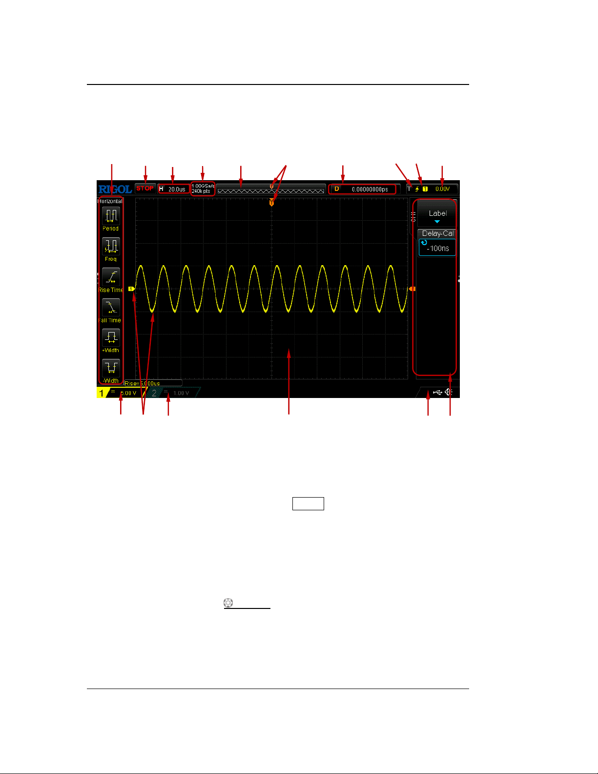
DS1000Z-E provides 7.0 inch WVGA (800*480) TFT LCD.
Figure 1-11 User Interface
1. Auto Measurement Items
Provide 20 horizontal (HORIZONTAL) and 17 vertical (VERTICAL) measurement
parameters. Press the softkey at the left of the screen to activate the
corresponding measurement item. Press MENU continuously to switch between
the horizontal and vertical parameters.
2. Status
Available states include RUN, STOP, T’D (triggered), WAIT and AUTO.
3. Horizontal Time Base
Represent the time per grid on the horizontal axis on the screen.
Use HORIZONTAL SCALE to modify this parameter. The range
available is from 2 ns to 50 s.
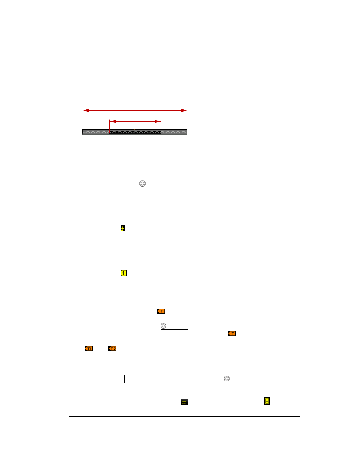
4. Sample Rate/Memory Depth
Display the current sample rate and memory depth of the oscilloscope.
The sample rate and memory depth will change in accordance with the
1-18 DS1000Z-E User Guide
Find Quality Products Online at: [email protected]
www.GlobalTestSupply.com
Page 38
Chapter 1 Quick Start RIGOL
waveform on the screen
waveform in the memory
horizontal time base.
5. Waveform Memory
Provide the schematic diagram of the memory position of the waveform
currently on the screen.
6. Trigger Position
Display the trigger position of the waveform in the waveform memory and on
the screen.
7. Horizontal Position
Use HORIZONTAL POSITION to modify this parameter. Press down the
knob to automatically set the parameter to zero.
8. Trigger Type
Display the currently selected trigger type and trigger condition setting.
Different labels are displayed when different trigger types are selected.
For example, represents triggering on the rising edge in "Edge" trigger.
9. Trigger Source
Display the trigger source currently selected (CH1, CH2, AC Line, or EXT).
Different labels are displayed when different trigger sources are selected and
the color of the trigger parameter area will change accordingly.
For example, denotes that CH1 is selected as the trigger source.
10. Trigger Level
When an analog channel is selected as the trigger source, you need to set a
proper trigger level.
The trigger level label is displayed at the right of the screen and the
trigger level value is displayed at the upper-right corner of the screen.
When using TRIGGER LEVEL to modify the trigger level, the trigger
level value will change with the up and down of .
Note: In slope trigger, runt trigger and window trigger, two trigger level labels
( and ) are displayed.
11. CH1 Vertical Scale
Display the voltage value per grid of CH1 waveform vertically.
Press CH1 to select CH1, and use VERTICAL SCALE to modify this
parameter.
The following labels will be displayed according to the current channel
setting: channel coupling (e.g. ) and bandwidth limit (e.g. ).
DS1000Z-E User Guide 1-19
Find Quality Products Online at: [email protected]
www.GlobalTestSupply.com
Page 39
RIGOL Chapter 1 Quick Start
Denote that the multifunction knob can be used to modify the
parameters. The backlight of turns on in the parameter modification
status.
Denote that you can use to select the desired items and the item
currently selected is displayed in blue. Press down to enter the menu
bar corresponding to the selected item. The backlight of is constant
on after menus with this symbol are selected.
Denote that you can press to open the pop-up numeric keyboard
and input the desired paramrter values directly. The backlight of is
constant on after menus with this symbol are selected.
Denote that the current menu has several options.
Denote that the current menu has a lower level menu.
Press this key to return to the previous menu.
The number of dots indicates the number of pages of the current menu.
12. Analog Channel Label/Waveform
Different channels are marked with different colors and the colors of the channel
label and waveform are the same.
13. CH2 Vertical Scale
Display the voltage value per grid of CH2 waveform vertically.
Press CH2 to select CH2, and use VERTICAL SCALE to modify this
parameter.
The following labels will be displayed according to the current channel
setting: channel coupling (e.g. ) and bandwidth limit (e.g. ).
14. Message Box
Display the prompt messages.
15. Notification Area
Display the sound icon and USB storage device icon.
Sound Icon: Press Utility Sound to enable or disable the sound. When
the sound is enabled, will be displayed; when the sound is disabled,
will be displayed.
USB Storage Device Icon: when a USB storage device is detected, will
be displayed.
16. Operation Menu
Press any softkey to activate the corresponding menu. The following symbols
might be displayed in the menu:
1-20 DS1000Z-E User Guide
Find Quality Products Online at: [email protected]
www.GlobalTestSupply.com
Page 40
Chapter 1 Quick Start RIGOL
Parameter Setting Method
DS1000Z-E supports the following two parameter setting methods.
Method one:
For the parameters with displayed on the menu, you can turn the multifunction
knob directly to set the desired values.
Method two:
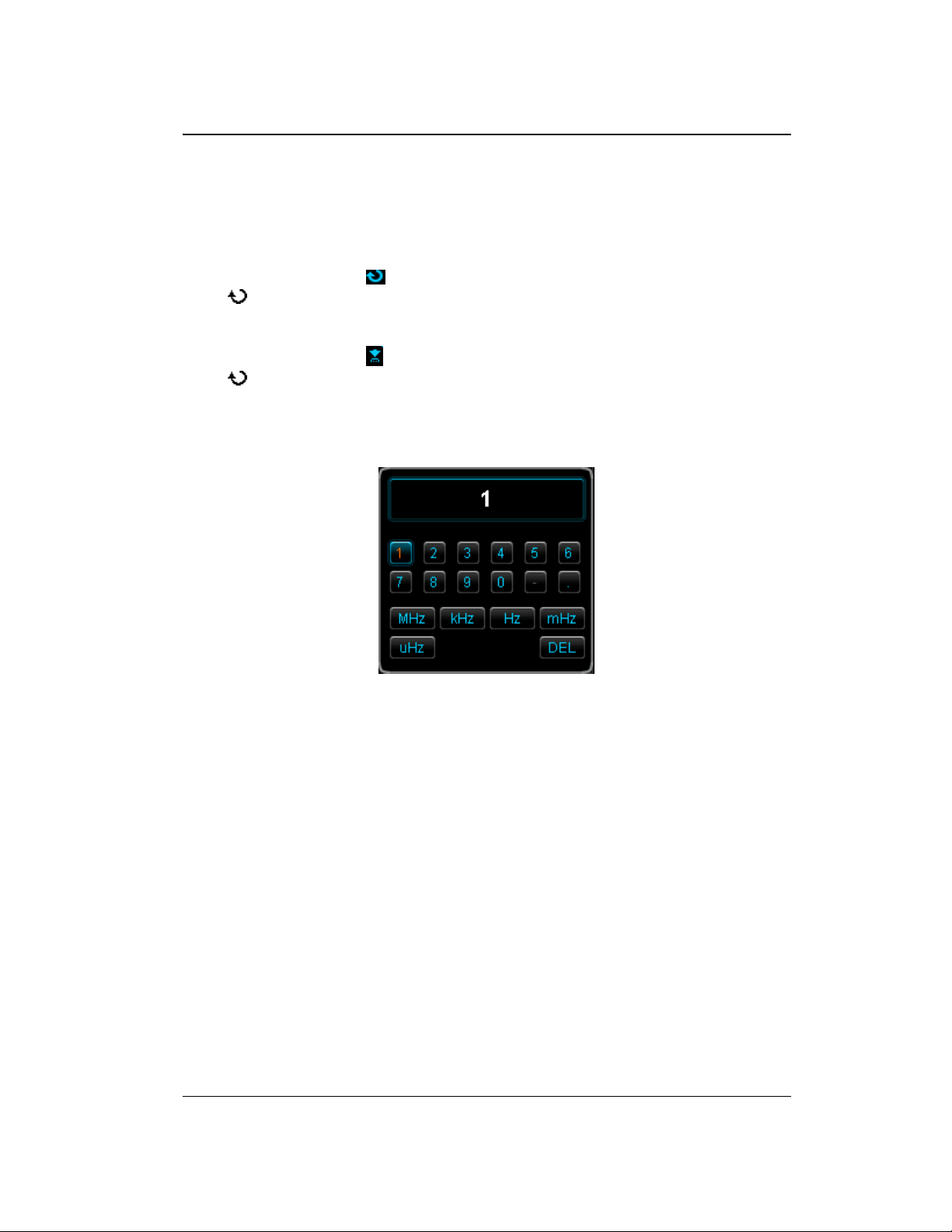
For the parameters with displayed on the menu, press down the multifunction
knob and the numeric keyboard as shown in the figure below is displayed. Turn
the knob to select the desired value and press down the knob to input the value.
After entering all the values, turn the knob to select the desired unit and press down
the knob to complete the parameter setting.
Figure 1-12 Numeric Keyboard
DS1000Z-E User Guide 1-21
Find Quality Products Online at: [email protected]
www.GlobalTestSupply.com
Page 41
RIGOL Chapter 1 Quick Start
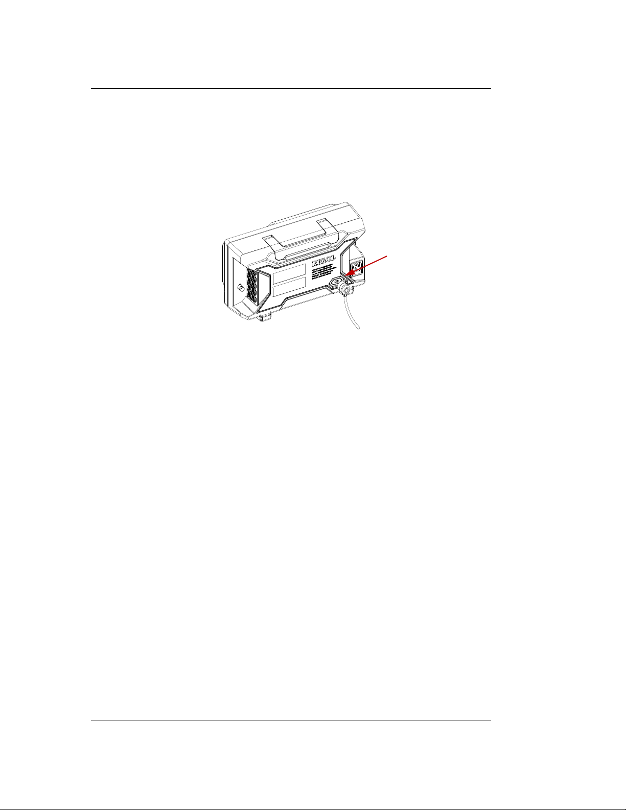
Security Lock Hole
To Use the Security Lock
If needed, you can use the security lock (please buy it yourself) to lock the
oscilloscope to a fixed location. The method is as follows, align the lock with the lock
hole and plug it into the lock hole vertically, turn the key clockwise to lock the
oscilloscope and then pull the key out.
Figure 1-13 To Use the Security Lock
Note: Please do not insert other articles into the security lock hole to avoid
damaging the instrument.
1-22 DS1000Z-E User Guide
Find Quality Products Online at: [email protected]
www.GlobalTestSupply.com
Page 42
Chapter 1 Quick Start RIGOL
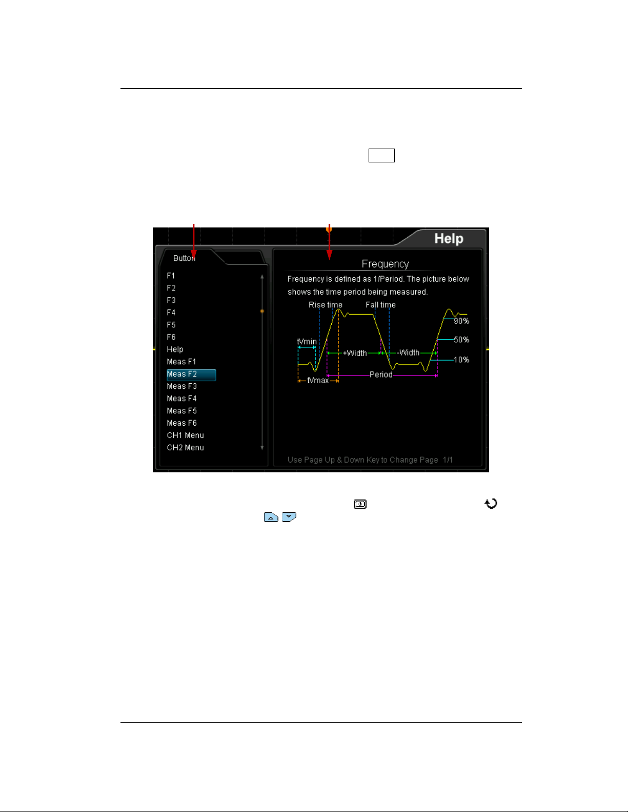
Help Options Help Display Area
To Use the Built-in Help System
The help system of this oscilloscope provides instructions for all the function keys
(including the menu keys) on the front panel. Press Help to open the help interface
and press again to close the interface. The help interface mainly consists of two parts.
The left are "Help Options". The right is the "Help Display Area".
Figure 1-14 Help Interface
You can press the button (except the Power key , the multifunction knob and
the menu page up/down key / ) directly on the front panel to get the
corresponding help information in the "Help Display Area".
DS1000Z-E User Guide 1-23
Find Quality Products Online at: [email protected]
www.GlobalTestSupply.com
Page 43
Chapter 2 To Set the Vertical System RIGOL
Chapter 2 To Set the Vertical System
The contents of this chapter:
To Enable the Analog Channel
Channel Coupling
Bandwidth Limit
Probe Ratio
Waveform Invert
Vertical Scale
Amplitude Unit
Channel Label
Delay Calibration of the Analog Channel
DS1000Z-E User Guide 2-1
Find Quality Products Online at: [email protected]
www.GlobalTestSupply.com
Page 44
RIGOL Chapter 2 To Set the Vertical System
To Enable the Analog Channel
DS1000Z-E provides 2 analog input channels (CH1 and CH2). As the setting methods
of the vertical systems of the two channels are the same, this chapter takes CH1 as
an example to illustrate the setting method of the vertical system.
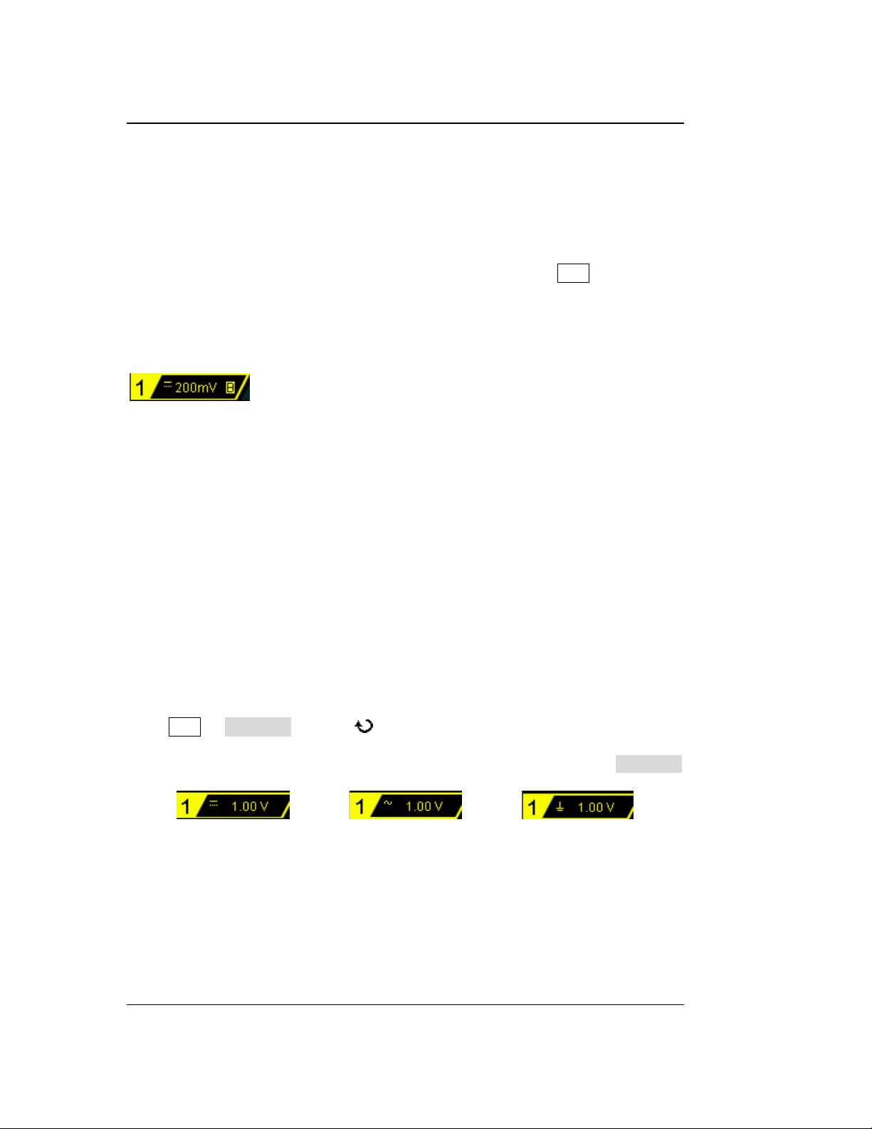
Connect a signal to the channel connector of CH1 and then press CH1 in the vertical
control area (VERTICAL) on the front panel to enable CH1. At this point, the channel
setting menu is displayed at the right side of the screen and the channel status label
at the bottom of the screen (as shown in the figure below) is highlighted. The
information displayed in the channel status label is related to the current channel
setting.
After the channel is turned on, modify the parameters such as the vertical scale,
horizontal time base, trigger mode and trigger level according to the input signal for
easy observation and measurement of the waveform.
Channel Coupling
The undesired signals can be filtered out by setting the coupling mode. For example,
the signal under test is a square waveform with DC offset.
When the coupling mode is "DC": the DC and AC components of the signal under
test can both pass the channel.
When the coupling mode is "AC": the DC components of the signal under test
are blocked.
When the coupling mode is "GND": the DC and AC components of the signal
under test are both blocked.
Press CH1 Coupling and use to select the desired coupling mode (the
default is DC). The current coupling mode is displayed in the channel status label at
the bottom of the screen as shown in the figure below. You can also press Coupling
continuously to switch the coupling mode.
DC AC GND
2-2 DS1000Z-E User Guide
Find Quality Products Online at: [email protected]
www.GlobalTestSupply.com
Page 45
Chapter 2 To Set the Vertical System RIGOL
Menu
Attenuation Ratio
(display amplitude of the signal : actual
amplitude of the signal)
0.01X
0.02X
0.05X
0.1X
0.2X
0.5X
1X
2X
5X
10X (the default value)
20X
50X
100X
200X
500X
1000X
0.01:1
0.02:1
0.05:1
0.1:1
0.2:1
0.5:1
1:1
2:1
5:1
10:1
20:1
50:1
100:1
200:1
500:1
1000:1
Bandwidth Limit
DS1000Z-E supports the bandwidth limit function which can reduce the display noise.
For example, the signal under test is a pulse with high frequency oscillation.
When the bandwidth limit is disabled, the high frequency components of the
signal under test can pass the channel.
When limiting the bandwidth to 20 MHz, the high frequency components of the
signal under test that exceed 20 MHz are attenuated.
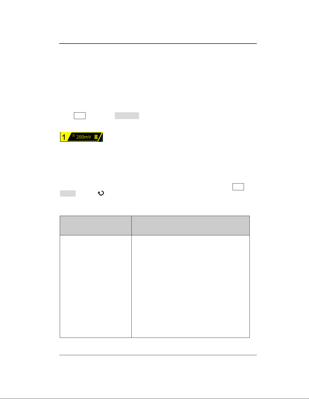
Press CH1, then press BW Limit continuously to switch the bandwidth limit state
(the default is OFF). When the bandwidth limit is enabled, the character "B" will be
displayed in the channel status label at the bottom of the screen.
Note: Bandwidth limit can reduce the noise as well as attenuate or eliminate the
high frequency components of the signal.
Probe Ratio
DS1000Z-E allows user to set the probe attenuation ratio manually. Press CH1
Probe and use to select the desired probe ratio. The probe ratio values available
are as shown in the table below.
Table 2-1 Probe Ratio
Find Quality Products Online at: [email protected]
DS1000Z-E User Guide 2-3
www.GlobalTestSupply.com
Page 46
RIGOL Chapter 2 To Set the Vertical System
(a) "Invert" Off
(b) "Invert" On
Waveform Invert
Press CH1 Invert to turn on or off waveform invert. When waveform invert is
turned off, the waveform display is normal; when waveform invert is turned on, the
waveform voltage values are inverted (as shown in the figures below).
Figure 2-1 Waveform Invert
Vertical Scale
Vertical scale refers to the voltage value per grid in the vertical direction on the
screen and is usually expressed as V/div.
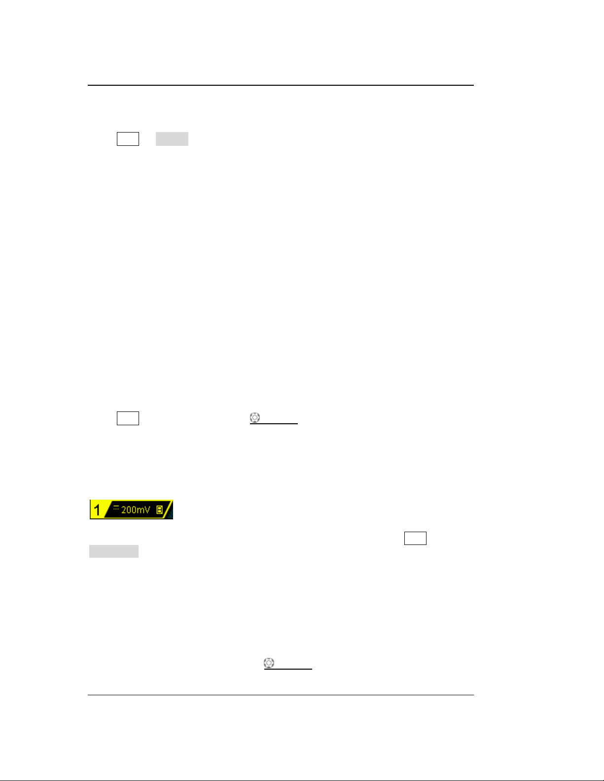
Press CH1 and rotate VERTICAL SCALE to adjust the vertical scale (clockwise
to reduce the scale and counterclockwise to increase). The size of the displayed
waveform will be changed accordingly. The scale information (as shown in the figure
below) in the channel label at the bottom of the screen will change accordingly
during the adjustment. The adjustable range of the vertical scale is related to the
probe ratio currently set. By default, the probe ratio is 10X and the adjustable range
of the vertical scale is from 10 mV/div to 100 V/div.
The vertical scale can be adjusted in "Coarse" or "Fine" mode. Press CH1
Volts/Div to switch the adjustment mode.
Coarse adjustment (take counterclockwise as an example): set the vertical scale
in 1-2-5 step namely 10 mV/div, 20 mV/div, 50 mV/div, 100 mV/div…100 V/div.
Fine adjustment: further adjust the vertical scale within a relatively smaller
range to improve vertical resolution. If the amplitude of the input waveform is a
little bit greater than the full scale under the current scale and the amplitude
would be a little bit lower if the next scale is used, fine adjustment can be used
to improve the amplitude of waveform display to view signal details.
Note: You can also press VERTICAL SCALE to quickly switch between "Coarse"
2-4 DS1000Z-E User Guide
Find Quality Products Online at: [email protected]
www.GlobalTestSupply.com
Page 47
Chapter 2 To Set the Vertical System RIGOL
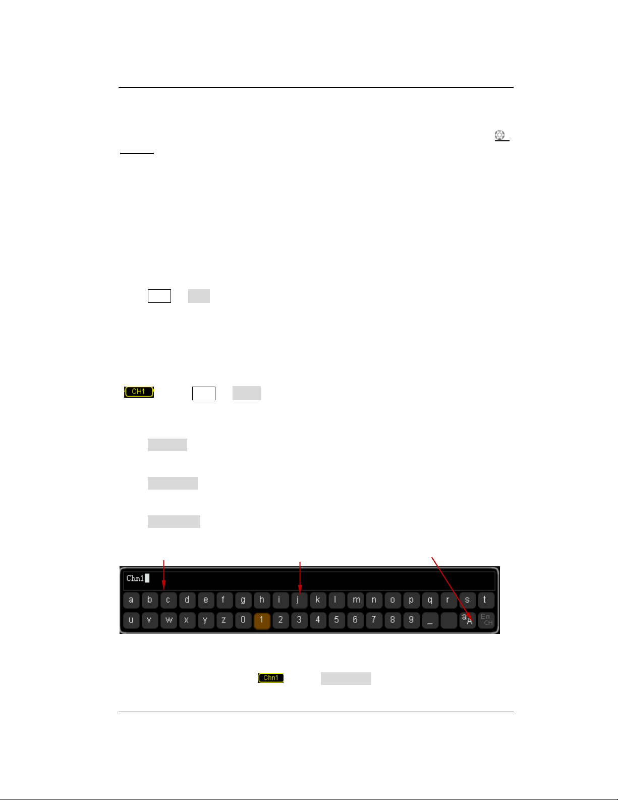
Name Input Area Keyboard Upper/Lower Case Switch
and "Fine" adjustments.
When changing the vertical scale of the analog channel by rotating VERTICAL
SCALE, you can select to expand or compress the waveform around the "Center" or
"Ground". For more details, please refer to the introduction in "Vertical
Reference".
Amplitude Unit
Select the amplitude display unit for the current channel. The available units are W, A,
V and U. When the unit is changed, the unit displayed in the channel label will
change accordingly.
Press CH1 Unit to select the desired unit and the default is V.
Channel Label
The instrument uses the number of the channel to mark the corresponding channel
by default. For ease of use, you can also set a label for each channel, for example,
" ". Press CH1 Label to enter the label setting menu. You can use the
built-in label or manually input a label. Manual input does not support the Chinese
input, and the length of the label cannot exceed 4 characters.
Press Display to turn on or off the channel label display. The default is CH1 when
the channel label display is enabled.
Press Template to select the preset labels such as CH1, ACK, ADDR, BIT, CLK, CS,
DATA, IN, MISO, MOSI, OUT, RX and TX, etc.
Press Label Edit and the label editing interface is automatically displayed as shown
in the figure below. You can input the label manually.
Figure 2-2 Label Editing Interface
For example, set the label to " ". Press Keyboard to select the "Keyboard" area.
DS1000Z-E User Guide 2-5
Find Quality Products Online at: [email protected]
www.GlobalTestSupply.com
Page 48
RIGOL Chapter 2 To Set the Vertical System
Select "Aa" using and press down to switch it to "aA". Select "C" using
and press down to input the character. Use the same method to input "hn1".
After finishing the input, press OK to finish the editing. If the Display is enabled,
the label will be displayed at the left of CH1 waveform.
To modify or delete the input character, press Name to select the "Name Input Area"
and use to select the character to be modified or deleted. Enter the desired
character or press Delete to delete the character selected.
2-6 DS1000Z-E User Guide
Find Quality Products Online at: [email protected]
www.GlobalTestSupply.com
Page 49
Chapter 2 To Set the Vertical System RIGOL
Horizontal Time Base
Delay Calibration Time Step
5 ns
100 ps
10 ns
200 ps
20 ns
400 ps
50 ns
1 ns
100 ns
2 ns
200 ns
4 ns
500 ns
10 ns
1 μs to 10 μs
20 ns
Delay Calibration of the Analog Channel
When using an oscilloscope for actual measurement, the transmission delay of the
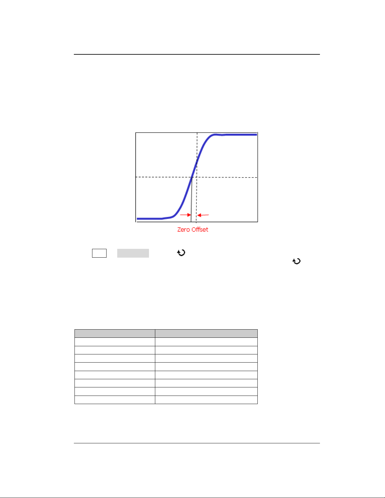
probe cable may bring relatively greater error (zero offset). DS1000Z-E supports user
to set a delay time to calibrate the zero offset of the corresponding channel. Zero
offset is defined as the offset of the crossing point of the waveform and trigger level
line relative to the trigger position, as shown in the figure below.
Figure 2-1 Zero Offset
Press CH1 Delay-Cal and use to set the desired delay time. The range
available is from -100 ns to 100 ns. Pressing down the multifunction knob will
reset the delay time to 0.00 s.
Note: This parameter is related to the instrument model and the current horizontal
time base setting. The larger the horizontal time base is, the larger the setting step
will be. Take DS1202Z-E as an example. The step values under different horizontal
time base are as shown in the table below.
Table 2-2 Relation between delay calibration time step and horizontal time base
Note: When the horizontal time base is equal to or greater than 10 μs, the delay
calibration time cannot be adjusted.
DS1000Z-E User Guide 2-7
Find Quality Products Online at: [email protected]
www.GlobalTestSupply.com
Page 50
Chapter 3 To Set the Horizontal System RIGOL
Chapter 3 To Set the Horizontal System
The contents of this chapter:
Delayed Sweep
Time Base Mode
DS1000Z-E User Guide 3-1
Find Quality Products Online at: [email protected]
www.GlobalTestSupply.com
Page 51
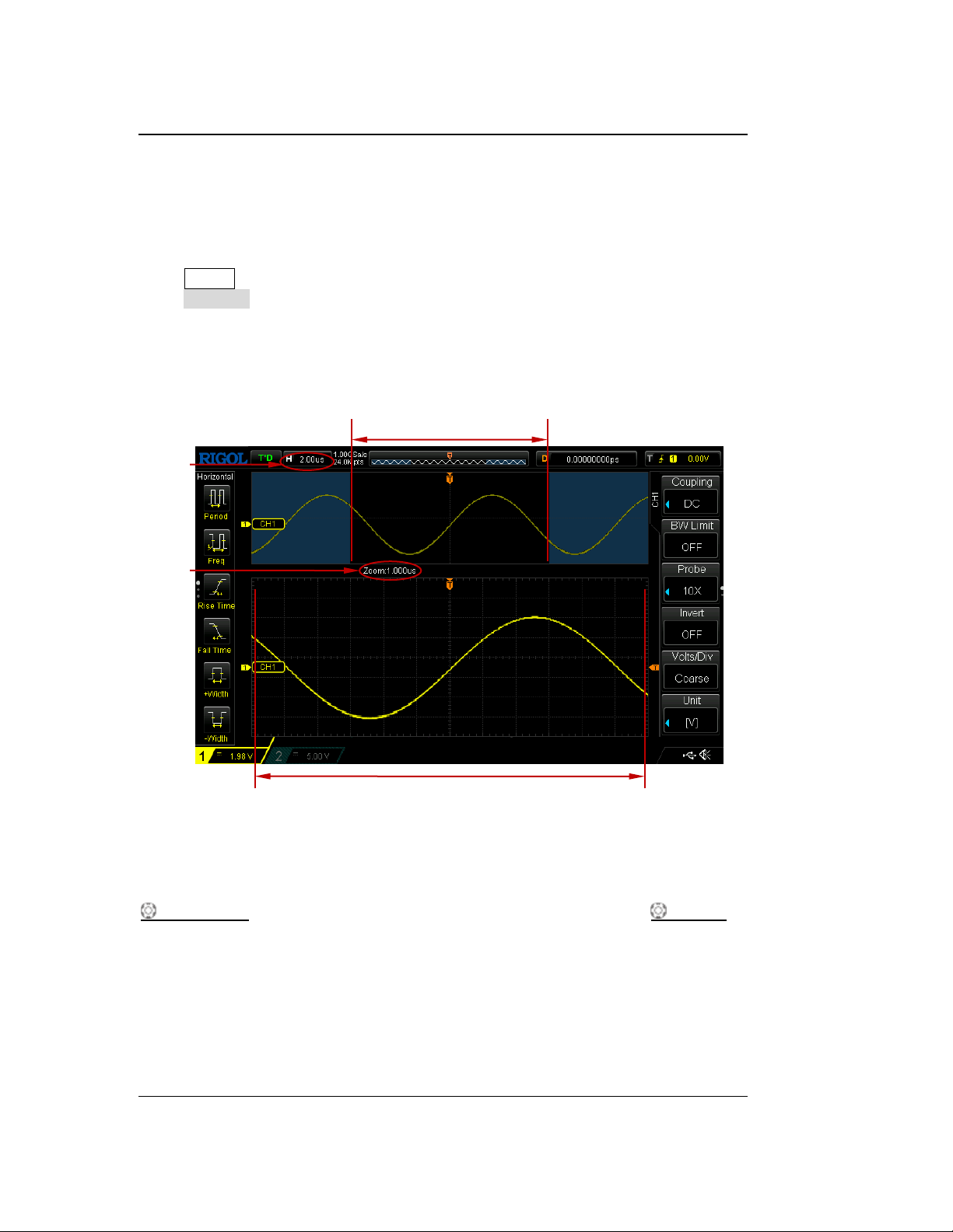
RIGOL Chapter 3 To Set the Horizontal System
放大后的波形
Main time
base
Delayed
Sweep
Time Base
The waveform before
enlargement
The waveform after enlargement
Delayed Sweep
Delayed sweep can be used to enlarge a length of waveform horizontally to view
waveform details.
Press MENU in the horizontal control area (HORIZONTAL) on the front panel and
press Delayed to enable or disable delayed sweep.
Note: To enable delayed sweep, the current time base mode must be "YT".
In delayed sweep mode, the screen is divided into two display areas as shown in the
figure below.
Figure 3-1 Delayed Sweep Mode
The waveform before enlargement:
The waveform in the area that is not covered by subtransparent blue in the upper
part of the screen is the waveform before enlargement. You can turn HORIZONTAL
POSITION to move the area left and right or turn HORIZONTAL SCALE to
enlarge or reduce this area.
The waveform after enlargement:
The waveform in the lower part of the screen is the horizontally expanded waveform.
Compared to the main time base, the delayed time base has increased the waveform
resolution (as shown in the figure above).
Note: The delayed time base should be less than or equal to the main time base.
3-2 DS1000Z-E User Guide
Find Quality Products Online at: [email protected]
www.GlobalTestSupply.com
Page 52
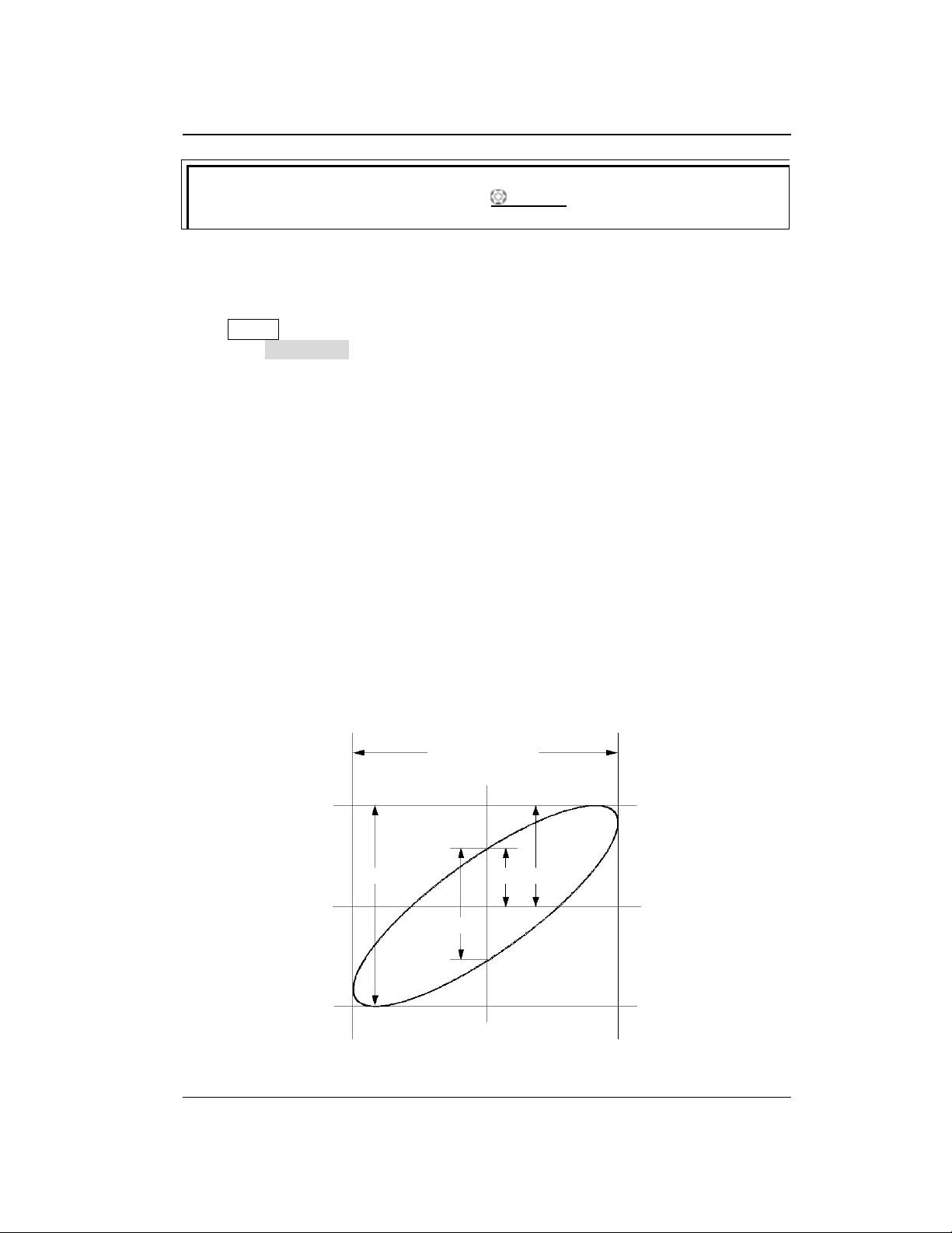
Chapter 3 To Set the Horizontal System RIGOL
Tip
You can also press down HORIZONTAL SCALE (delayed sweep shortcut key)
to directly switch to the delayed sweep mode.
II I
III IV
The signal must be
centered horizontally
A B C
D
II I
III IV
The signal must be
centered horizontally
Time Base Mode
Press MENU in the horizontal control area (HORIZONTAL) on the front panel and
then press Time Base to select the time base mode of the oscilloscope. The default
is YT.
YT Mode
In this mode, the Y axis represents voltage and the X axis represents time.
Note: Only when this mode is enabled, can "Delayed Sweep" be turned on. In this
mode, when the horizontal time base is greater than or equal to 200 ms, the
instrument enters slow sweep mode. For the details, please refer to the introduction
of slow sweep in "Roll Mode".
XY Mode
In this mode, the oscilloscope changes the two channels from voltage-time display
mode to voltage-voltage display mode. The phase deviation between two signals
with the same frequency can be easily measured via Lissajous method. The figure
below shows the measurement schematic diagram of the phase deviation.
Figure 3-2 Measurement Schematic Diagram of Phase Deviation
DS1000Z-E User Guide 3-3
Find Quality Products Online at: [email protected]
www.GlobalTestSupply.com
Page 53
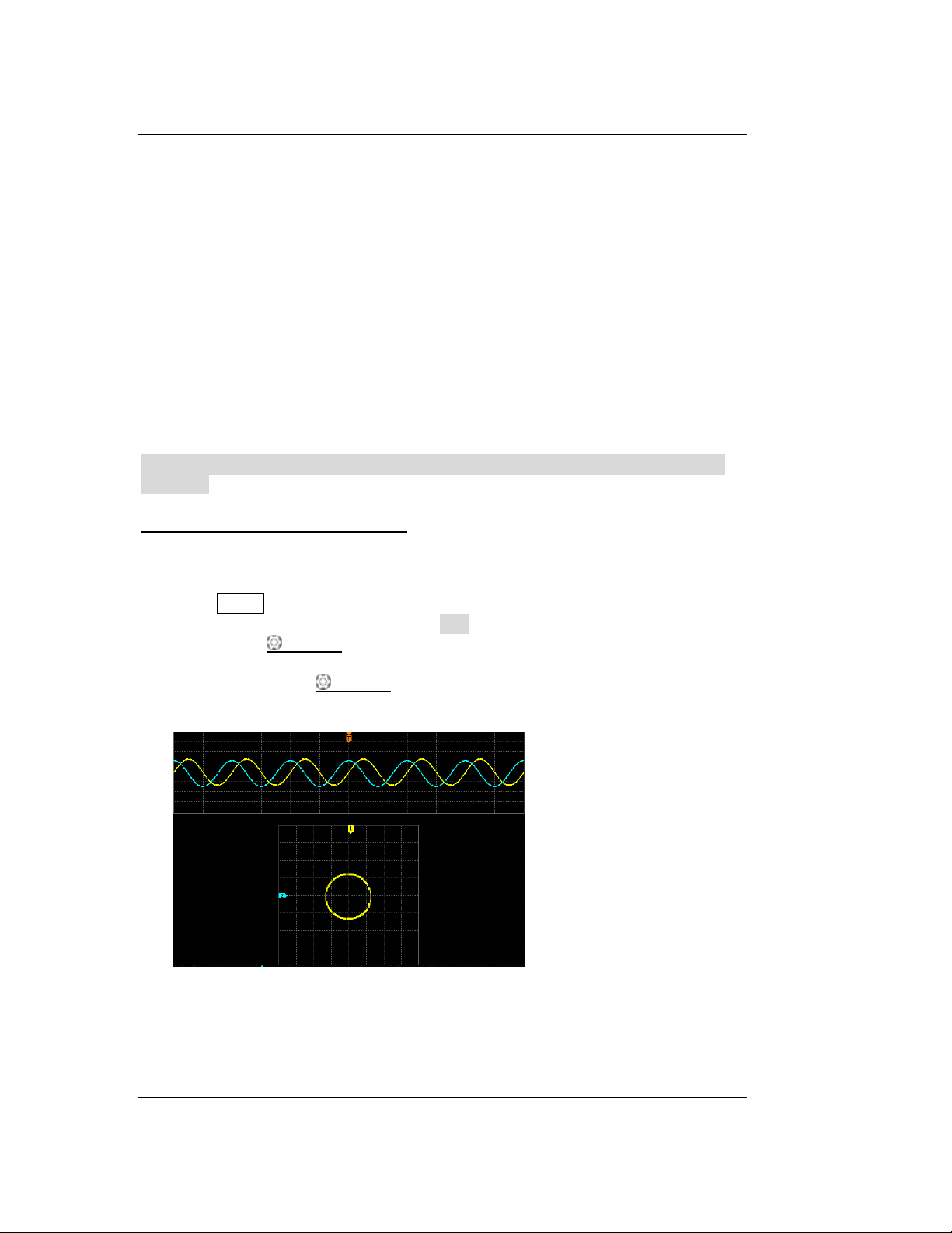
RIGOL Chapter 3 To Set the Horizontal System
According to sin=A/B or C/D (wherein, is the phase deviation angle between
the two channels and the definitions of A, B, C and D are as shown in the figure
above), the phase deviation angle is obtained, that is:
=arcsin (A/B) or arcsin (C/D)
If the principal axis of the ellipse is within quadrant I and III, the phase deviation
angle obtained should be within quadrant I and IV, namely within (0 to π/2) or (3π/2
to 2π). If the principal axis of the ellipse is within quadrant II and IV, the phase
deviation angle obtained should be within quadrant II and III, namely within (π/2 to
π) or (π to 3π/2).
The XY function can be used to measure the phase deviation occurred when the
signal under test passes through a circuit network. Connect the oscilloscope to the
circuit to monitor the input and output signals of the circuit.
Application example: measure the phase deviation of the input signals of two
channels.
Method 1: Use Lissajous method
1. Connect a sine signal to CH1 and then connect a sine signal with the same
frequency and amplitude but a 90° phase deviation to CH2.
2. Press AUTO and then adjust the vertical positions of CH1 and CH2 to 0 V.
3. Set the time base mode to XY, press X-Y and select "CH1-CH2". Rotate
Horizontal SCALE to adjust the sample rate properly to get better
Lissajous figure for better observation and measurement.
4. Rotate VERTICAL SCALE of CH1 and CH2 to make the signals easy to
observe. At this point, the circle as shown in the figure below should be
displayed.
5. Observe the measurement result shown in the figure above. According to the
measurement schematic diagram of the phase deviation (as shown in Figure
3-2), A/B (C/D) = 1. Thus, the phase deviation angle =arcsin1=90°.
3-4 DS1000Z-E User Guide
Find Quality Products Online at: [email protected]
www.GlobalTestSupply.com
Page 54
Chapter 3 To Set the Horizontal System RIGOL
Slow Sweep
Slow sweep is similar to Roll mode. In YT mode, when the horizontal time base is
set to 200 ms/div or slower, the instrument enters "slow sweep" mode in which the
instrument first acquires the data at the left of the trigger point and then waits for a
trigger event. After the trigger occurs, the instrument continues to finish the
waveform at the right of the trigger point. When slow sweep mode is used to
observe low frequency signal, DC "Channel Coupling" mode is recommended.
Note:
The maximum sample rate of XY mode is 500 MSa/s. Generally, longer sample
waveform can ensure better display effect of Lissajous figure. But due to the
limitation of the memory depth, you have to reduce the waveform sample rate
to acquire longer waveform (refer to the introduction in "Memory Depth").
Therefore, during the measurement, reducing the sample rate properly can
acquire better display effect of Lissajous figure.
When XY mode is enabled, "Delayed Sweep" will be disabled automatically.
Press X-Y to select "CH1-CH2", and the instrument automatically turns on the
two corresponding channels. The X-axis tracks the voltage of the first channel;
the Y-axis tracks the voltage of the second channel.
The following functions are not available in XY mode:
"Delayed Sweep", "Vectors", "Protocol Decoding", "Acquisition Mode",
"Pass/Fail Test", "Waveform Record", and "To Set the Persistence
Time".
Method 2: Use the shortcut measurement function
Please refer to "Phase 12" and "Phase 12" measurement functions of "Delay
and Phase" on page 6-27.
Roll Mode
In this mode, the waveform scrolls from right to left to update the display.
The horizontal position and trigger control of the waveform are not available. The
range of horizontal scale adjustment is from 200 ms to 50.0 s.
Note: When Roll mode is enabled, the waveform "horizontal position", "Delayed
Sweep", "Protocol Decoding", "Pass/Fail Test", "Waveform Record", "To
Set the Persistence Time" and "To Trigger the Oscilloscope" are not available.
Find Quality Products Online at: [email protected]
DS1000Z-E User Guide 3-5
www.GlobalTestSupply.com
Page 55
Chapter 4 To Set the Sample System RIGOL
Chapter 4 To Set the Sample System
The contents of this chapter:
Acquisition Mode
Sin(x)/x
Sample Rate
Memory Depth
Anti-aliasing
DS1000Z-E User Guide 4-1
Find Quality Products Online at: [email protected]
www.GlobalTestSupply.com
Page 56
RIGOL Chapter 4 To Set the Sample System
Acquisition Mode
The acquisition mode is used to control how to generate waveform points from
sample points.
Press Acquire Mode on the front panel and use to select the desired
acquisition mode (the default is normal), then press down the knob to select this
mode. You can also press Mode continuously to switch the acquisition mode.
Normal
In this mode, the oscilloscope samples the signal at equal time interval to rebuild the
waveform. For most of the waveforms, the best display effect can be obtained using
this mode.
Peak Detect
In this mode, the oscilloscope acquires the maximum and minimum values of the
signal within the sample interval to get the envelope of the signal or the narrow pulse
of the signal that might be lost. In this mode, signal confusion can be prevented but
the noise displayed would be larger.
In this mode, the oscilloscope can display all the pulses with pulse widths at least as
wide as the sample period.
Average
In this mode, the oscilloscope averages the waveforms from multiple samples to
reduce the random noise of the input signal and improve the vertical resolution.
Greater number of averages can lower the noise and increase the vertical resolution;
while at the same time, it will slow the response of the displayed waveform to the
waveform changes.
When "Average" mode is selected, press Averages and use to set the desired
number of averages. The number of averages can be set to 2, 4, 8, 16, 32, 64, 128,
256, 512 or 1024. The default is 2.
4-2 DS1000Z-E User Guide
Find Quality Products Online at: [email protected]
www.GlobalTestSupply.com
Page 57
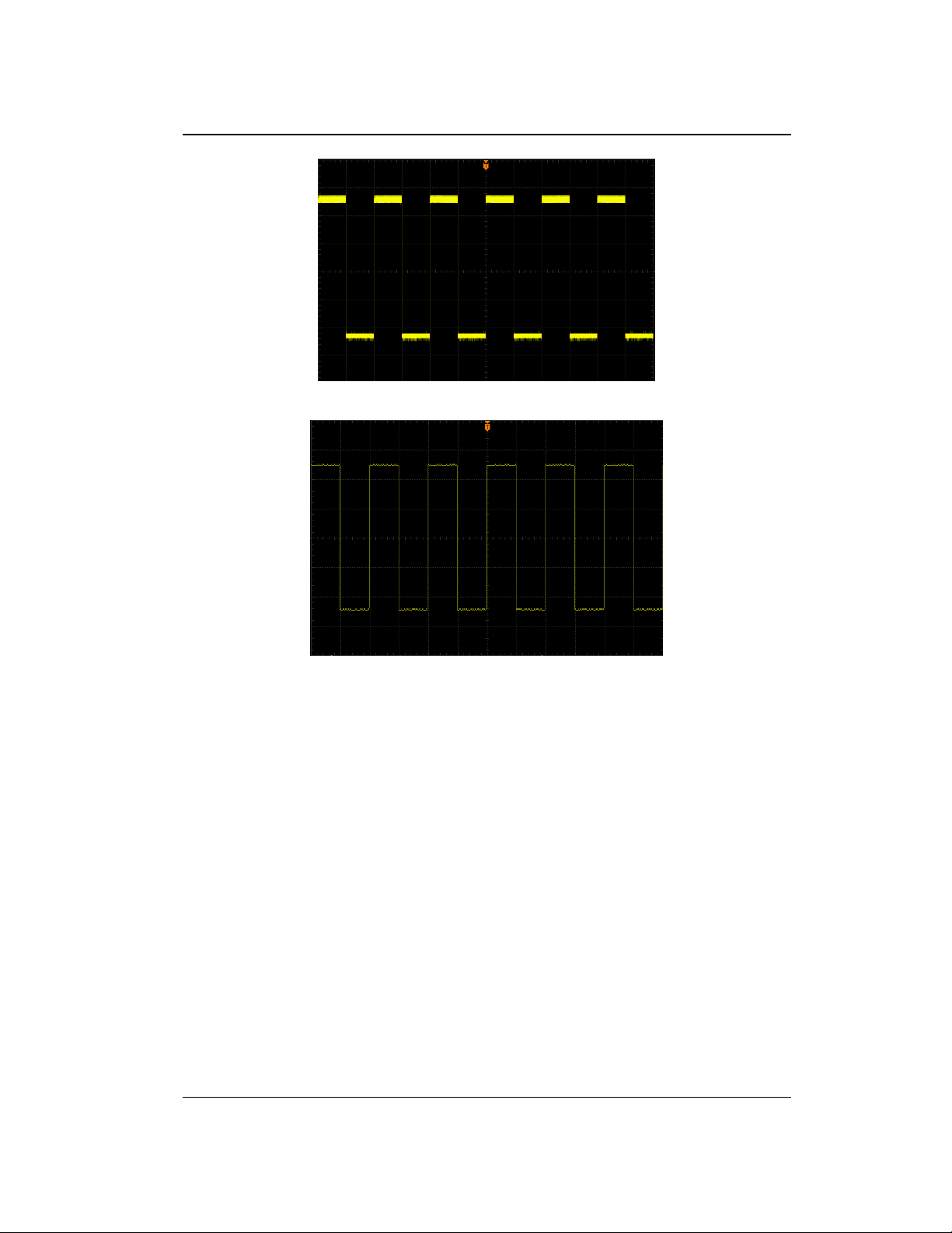
Chapter 4 To Set the Sample System RIGOL
Figure 4-1 The Waveform before Average
Figure 4-2 The Waveform after 256 Averages
High Resolution
This mode uses a kind of ultra-sample technique to average the neighboring points
of the sample waveform to reduce the random noise on the input signal and generate
much smoother waveforms on the screen. This is generally used when the sample
rate of the digital converter is higher than the storage rate of the acquisition memory.
Note: "Average" and "High Res" modes use different averaging methods. The
former uses "Multi-sample Average" and the latter uses "Single Sample Average".
DS1000Z-E User Guide 4-3
Find Quality Products Online at: [email protected]
www.GlobalTestSupply.com
Page 58
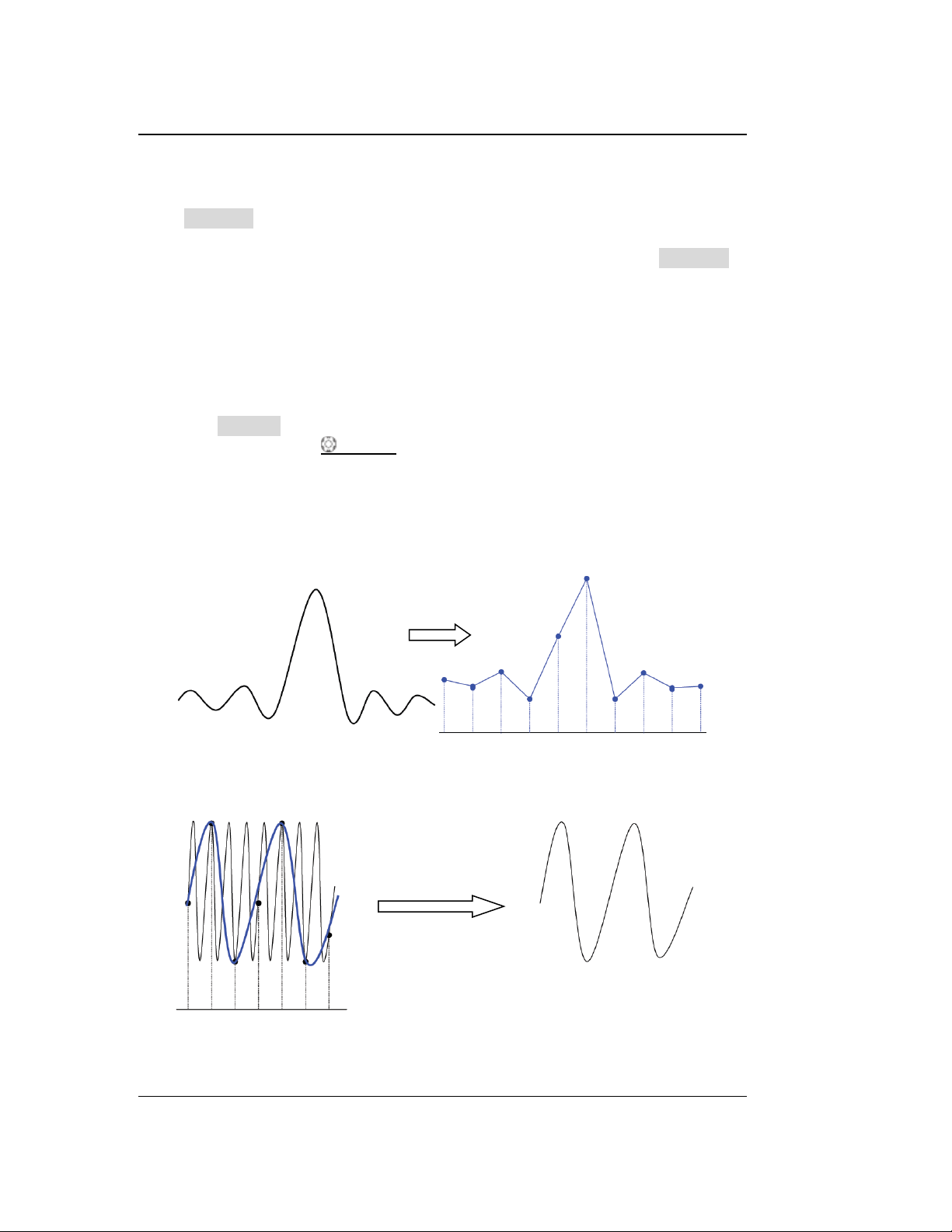
RIGOL Chapter 4 To Set the Sample System
Sin(x)/x
Press Sin(x)/x to enable or disable the dynamic sine interpolation function which
can acquire better restoration of the original waveform.
Note: If the number of channels currently turned on is less than three, Sin(x)/x is
grayed out and disabled.
Sample Rate
The maximum sample rate of DS1000Z-E is 1 GSa/s.
Note: The sample rate is displayed in the status bar at the upper side of the screen
and in the Sa Rate menu and can be changed by adjusting the horizontal time base
through HORIZONTAL SCALE or modifying the "Memory Depth".
The influence on the waveform when the sample rate is too low:
1. Waveform Distortion: when the sample rate is too low, some waveform
details are lost and the waveform displayed is rather different from the actual
signal.
2. Waveform Confusion: when the sample rate is lower than twice the actual
signal frequency (Nyquist Frequency), the frequency of the waveform rebuilt
from the sample data is lower than the actual signal frequency.
4-4 DS1000Z-E User Guide
Find Quality Products Online at: [email protected]
www.GlobalTestSupply.com
Page 59
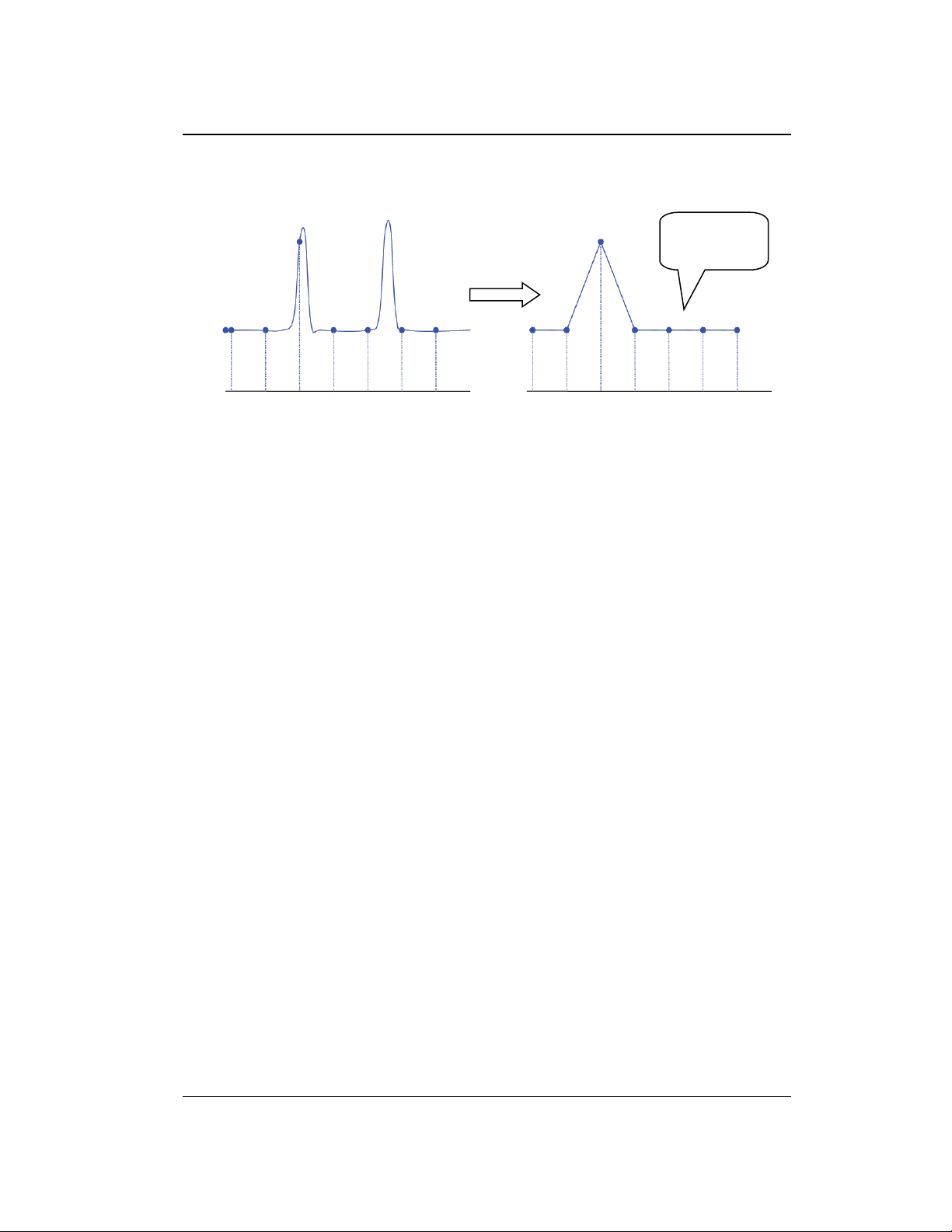
Chapter 4 To Set the Sample System RIGOL
Pulse
disappeared
3. Waveform Leakage: when the sample rate is too low, the waveform rebuilt
from the sample data does not reflect all the actual signal information.
DS1000Z-E User Guide 4-5
Find Quality Products Online at: [email protected]
www.GlobalTestSupply.com
Page 60
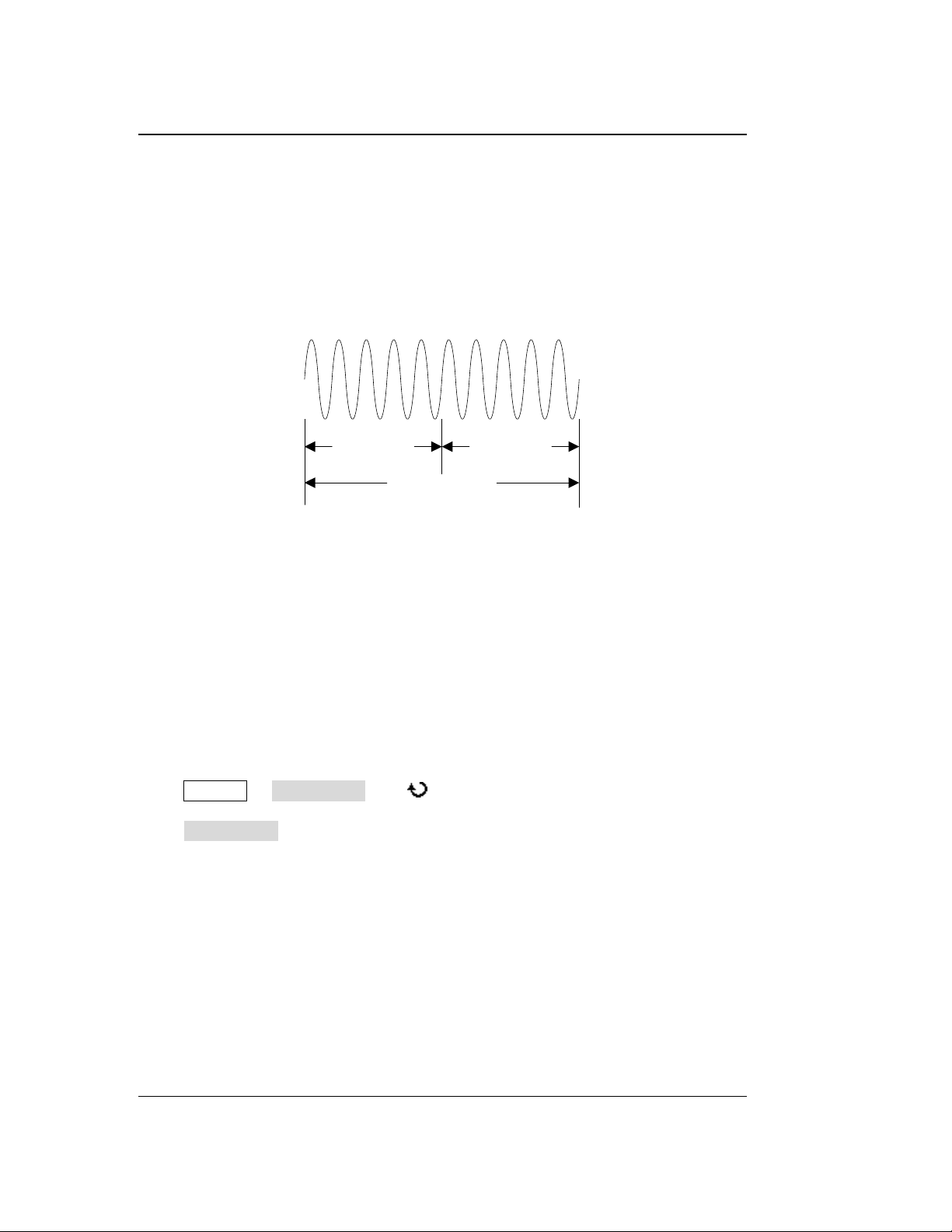
RIGOL Chapter 4 To Set the Sample System
T
Trigger Point
Pre-sample Delayed Sample
Memory Depth
MDepth SRate TScale HDivs
MDepth
SRate
TScale
HDivs
Memory Depth
Memory depth refers to the number of waveform points that the oscilloscope can
store in a single trigger sample and it reflects the storage ability of the sample
memory. DS1000Z-E provides up to 24 Mpts standard memory depth.
Figure 4-1 Memory Depth
The relation of memory depth, sample rate and horizontal time base scale fulfills the
equation below:
: Memory depth. The unit is pts.
: Sample rate. The unit is Sa/s.
: Horizontal time base scale. The unit is s/div.
: Number of grids horizontally. The unit is div. For DS1000Z-E, this value is 12.
Therefore, under the same horizontal time base scale, higher memory depth can
ensure higher sample rate.
Press Acquire Mem Depth, use to switch to the desired memory depth (the
default is auto) and then press down the knob to select the option. You can also
press Mem Depth continuously to switch the memory depth.
― When a single channel is enabled, the memory depths available include
Auto, 12kPoints, 120kPoints, 1.2MPoints, 12MPoints and 24MPoints.
― When dual channels are enabled, the memory depths available include Auto,
6kPoints, 60kPoints, 600kPoints, 6MPoints and 12MPoints.
Note: In "Auto" mode, the oscilloscope selects the memory depth automatically
according to the current sample rate.
(4-1)
4-6 DS1000Z-E User Guide
Find Quality Products Online at: [email protected]
www.GlobalTestSupply.com
Page 61
Chapter 4 To Set the Sample System RIGOL
Anti-aliasing
At slower sweep speed, the sample rate is reduced and a dedicated display algorithm
can be used to minimize the possibility of aliasing.
Press Acquire Anti-aliasing to enable or disable the anti-aliasing function. By
default, anti-aliasing is disabled and waveform aliasing is more possible.
DS1000Z-E User Guide 4-7
Find Quality Products Online at: [email protected]
www.GlobalTestSupply.com
Page 62
Chapter 5 To Trigger the Oscilloscope RIGOL
Chapter 5 To Trigger the Oscilloscope
As for trigger, you set certain trigger condition according to the requirement and
when a waveform in the waveform stream meets this condition, the oscilloscope
captures this waveform as well as the neighbouring part and displays them on the
screen. For digital oscilloscope, it samples waveform continuously no matter whether
it is stably triggered, but only stable trigger can ensure stable display. The trigger
module ensures that every time base sweep or acquisition starts from the
user-defined trigger condition, namely every sweep is synchronous to the acquisition
and the waveforms acquired overlap to display stable waveform.
Trigger setting should be based on the features of the input signal, thus you need to
have some knowledge of the signal under test to quickly capture the desired
waveform. This oscilloscope provides abundant advanced trigger functions which can
help you to focus on the desired waveform details.
The contents of this chapter:
Trigger Source
Trigger Mode
Trigger Coupling
Trigger Holdoff
Noise Rejection
Trigger Type
Trigger Output Connector
DS1000Z-E User Guide 5-1
Find Quality Products Online at: [email protected]
www.GlobalTestSupply.com
Page 63
RIGOL Chapter 5 To Trigger the Oscilloscope
Trigger Source
Press MENU Source in the trigger control area (TRIGGER) on the front panel to
select the desired trigger source. Analog channels CH1 and CH2, EXT (external
trigger), or the AC Line can all be used as trigger source.
Analog channel input:
Signals input from analog channels CH1 and CH2 can all be used as trigger source.
No matter whether the channel selected is enabled, the channel can work normally.
External trigger input:
The trigger signal (e.g. external clock or signal of the circuit under test) input via the
external trigger input terminal [EXT TRIG] connector can be used as the trigger
source. When the trigger source is selected, rotate TRIGGER LEVEL to set the
trigger level within the range from -4 V to 4 V.
When the two analog channels are used to acquire data, you can connect the trigger
signal via the [EXT TRIG] connector and use the signal as the external trigger
source.
AC line:
The trigger signal is obtained from the AC power input of the oscilloscope. AC trigger
is usually used to measure signals relevant to the AC power frequency. For example,
stably trigger the waveform output from the transformer of a transformer substation;
it is mainly used in related measurements of the power industry.
5-2 DS1000Z-E User Guide
Find Quality Products Online at: [email protected]
www.GlobalTestSupply.com
Page 64
Chapter 5 To Trigger the Oscilloscope RIGOL
Pre-trigger Buffer
Post-trigger Buffer
Trigger Event
Acquisition Memory
Trigger Mode
The following is the schematic diagram of the acquisition memory. To easily
understand the trigger event, the acquisition memory is divided into the pre-trigger
buffer and post-trigger buffer.
Figure 5-1 Schematic Diagram of the Acquisition Memory
After the system runs, the oscilloscope operates by first filling the pre-trigger buffer.
It starts searching for a trigger after the pre-trigger buffer is filled. While searching
for the trigger, the data sampled will still be transmitted to the pre-trigger buffer (the
new data will continuously overwrite the previous date). When a trigger is found, the
pre-trigger buffer contains the data acquired just before the trigger. Then, the
oscilloscope will fill the post-trigger buffer and display the data in the acquisition
memory. If the acquisition is activated via RUN/STOP, the oscilloscope will repeat
this process; if the acquisition is activated via SINGLE, the oscilloscope will stop
after finishing a single acquisition (you can pan and zoom the waveform currently
displayed).
Press MODE in the trigger control area (TRIGGER) on the front panel or press
MENU Sweep to select the desired trigger mode. The corresponding status light
of the mode currently selected turns on.
Auto: in this trigger mode, the oscilloscope will force a trigger if the specified
trigger condition is not found.
Normal: in this trigger mode, the oscilloscope only triggers when the specified
trigger condition is found.
Single: in this trigger mode, the oscilloscope generates a trigger when the
specified trigger condition is found and then stops.
Note: In "Normal" and "Single" trigger modes, pressing FORCE can generate a
trigger signal forcibly.
DS1000Z-E User Guide 5-3
Find Quality Products Online at: [email protected]
www.GlobalTestSupply.com
Page 65
RIGOL Chapter 5 To Trigger the Oscilloscope
Trigger Coupling
Trigger coupling decides which kind of components will be transmitted to the trigger
module. Please distinguish it from "Channel Coupling".
DC: allow DC and AC components into the trigger path.
AC: block all the DC components and attenuate signals lower than 75 Hz.
LF Reject: block the DC components and reject the low frequency components
(lower than 75 kHz).
HF Reject: reject the high frequency components (higher than 75 kHz).
Press MENU Setting Coupling in the trigger control area (TRIGGER) on the
front panel to select the desired coupling type (the default is DC).
Note: Trigger coupling is only valid in edge trigger.
5-4 DS1000Z-E User Guide
Find Quality Products Online at: [email protected]
www.GlobalTestSupply.com
Page 66
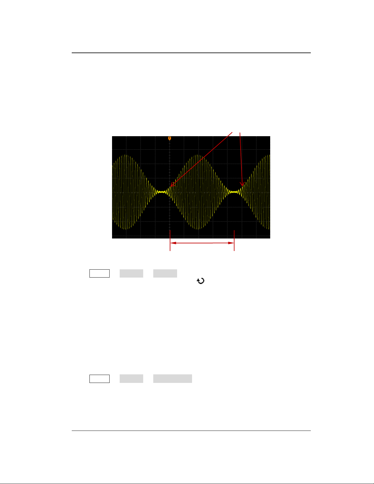
Chapter 5 To Trigger the Oscilloscope RIGOL
Trigger Position
Holdoff Time
Trigger Holdoff
Trigger holdoff can be used to stably trigger complex waveforms (such as modulated
waveform). Holdoff time is the amount of time that the oscilloscope waits for
re-arming the trigger module after generating a correct trigger. The oscilloscope will
not trigger even if the trigger condition is met during the holdoff time and will only
re-arm the trigger module after the holdoff time expires.
Figure 5-2 Schematic Diagram of Trigger Holdoff
Press MENU Setting Holdoff in the trigger control area (TRIGGER) on the
front panel and use the multifunction knob to modify the holdoff time (the
default is 16 ns) until the waveform triggers stably. The adjustable range of holdoff
time is from 16 ns to 10 s.
Note: Trigger holdoff is not available for video trigger, timeout trigger, setup/hold
trigger, Nth edge trigger, RS232 trigger, I2C trigger and SPI trigger.
Noise Rejection
Noise rejection can reject the high frequency noise in the signal and reduce the
possibility of miss-trigger of the oscilloscope.
Press MENU Setting NoiseReject in the trigger control area (TRIGGER) on
the front panel to enable or disable noise rejection.
DS1000Z-E User Guide 5-5
Find Quality Products Online at: [email protected]
www.GlobalTestSupply.com
Page 67
RIGOL Chapter 5 To Trigger the Oscilloscope
Trigger Type
DS1000Z-E provides various trigger functions. Among various trigger types, RS232
trigger, I2C trigger and SPI trigger are serial bus triggers.
Edge Trigger
Pulse Trigger
Slope Trigger
Video Trigger
Pattern Trigger
Duration Trigger
TimeOut Trigger
Runt Trigger
Window Trigger
Delay Trigger
Setup/Hold Trigger
Nth Edge Trigger
RS232 Trigger
I2C Trigger
SPI Trigger
5-6 DS1000Z-E User Guide
Find Quality Products Online at: [email protected]
www.GlobalTestSupply.com
Page 68
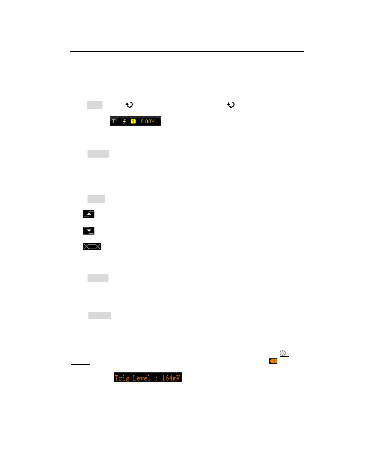
Chapter 5 To Trigger the Oscilloscope RIGOL
Edge Trigger
Trigger on the trigger threshold of the specified edge of the input signal.
Trigger Type:
Press Type, rotate to select "Edge" and press down . At this point, the trigger
setting information is displayed at the upper right corner of the screen.
For example, . The trigger type is edge trigger; the trigger source
is CH1; the trigger level is 0.00 V.
Source Selection:
Press Source to open the signal source list and select CH1-CH2, AC, or EXT. For the
details, please refer to the introduction in "Trigger Source". The current trigger
source is displayed at the upper right corner of the screen.
Note: Select channel with signal input as trigger source to obtain stable trigger.
Edge Type:
Press Slope to select the kind of edge of the input signal on which the oscilloscope
triggers. The current edge type is displayed at the upper right corner of the screen.
: trigger on the rising edge of the input signal when the voltage level meets
the preset trigger level.
: trigger on the falling edge of the input signal when the voltage level meets
the preset trigger level.
: trigger on the rising or falling edge of the input signal when the voltage
level meets the preset trigger level.
Trigger Mode:
Press Sweep to open the trigger mode list and select auto, normal or single. For the
details, please refer to "Trigger Mode". The corresponding status light of the
current trigger mode turns on.
Trigger Setting:
Press Setting to set the trigger parameters (trigger coupling, trigger holdoff and
noise rejection) under this trigger type.
Trigger Level:
When the trigger source is an analog channel, trigger occurs only when the signal
reaches the preset trigger level. You can modify the level using TRIGGER
LEVEL. At this point, an orange trigger level line and the trigger mark " " appear
on the screen and move up and down with the rotation of the knob. The trigger level
value (such as ) at the lower left corner of the screen also
changes accordingly. When stopping turning the knob, the trigger level line
disappears in about 2 s.
DS1000Z-E User Guide 5-7
Find Quality Products Online at: [email protected]
www.GlobalTestSupply.com
Page 69
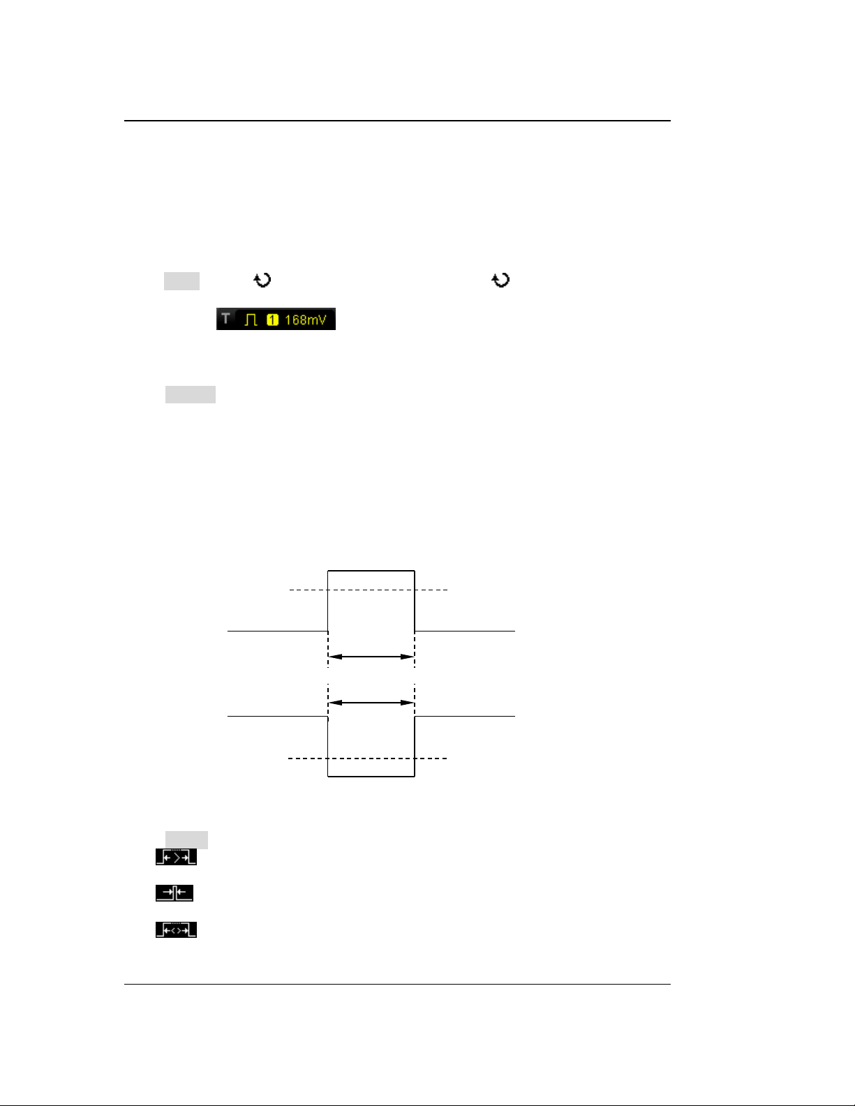
RIGOL Chapter 5 To Trigger the Oscilloscope
Positive
pulse width
Trigger level
Trigger level
Negative
pulse width
A
B
A
B
Pulse Trigger
Trigger on the positive or negative pulse with a specified width. In this mode, the
oscilloscope will trigger when the pulse width of the input signal satisfies the
specified pulse width condition.
Trigger Type:
Press Type, rotate to select "Pulse" and press down . At this point, the trigger
setting information is displayed at the upper right corner of the screen.
For example, . The trigger type is pulse trigger; the trigger source
is CH1; the trigger level is 168 mV.
Source Selection:
Press Source to open the signal source list and select CH1, CH2, or EXT. For the
details, please refer to the introduction in "Trigger Source". The current trigger
source is displayed at the upper right corner of the screen.
Note: Select channel with signal input as trigger source to obtain stable trigger.
Pulse Condition:
In this oscilloscope, positive pulse width is defined as the time difference between
the two crossing points of the trigger level and positive pulse; negative pulse width is
defined as the time difference between the two crossing points of the trigger level
and negative pulse, as shown in the figure below.
Figure 5-3 Positive Pulse Width/Negative Pulse Width
Press When to select the desired pulse width condition.
: trigger when the positive pulse width of the input signal is greater than
the specified pulse width.
: trigger when the positive pulse width of the input signal is lower than the
specified pulse width.
: trigger when the positive pulse width of the input signal is greater than
the specified lower limit of pulse width and lower than the specified upper limit
5-8 DS1000Z-E User Guide
Find Quality Products Online at: [email protected]
www.GlobalTestSupply.com
Page 70
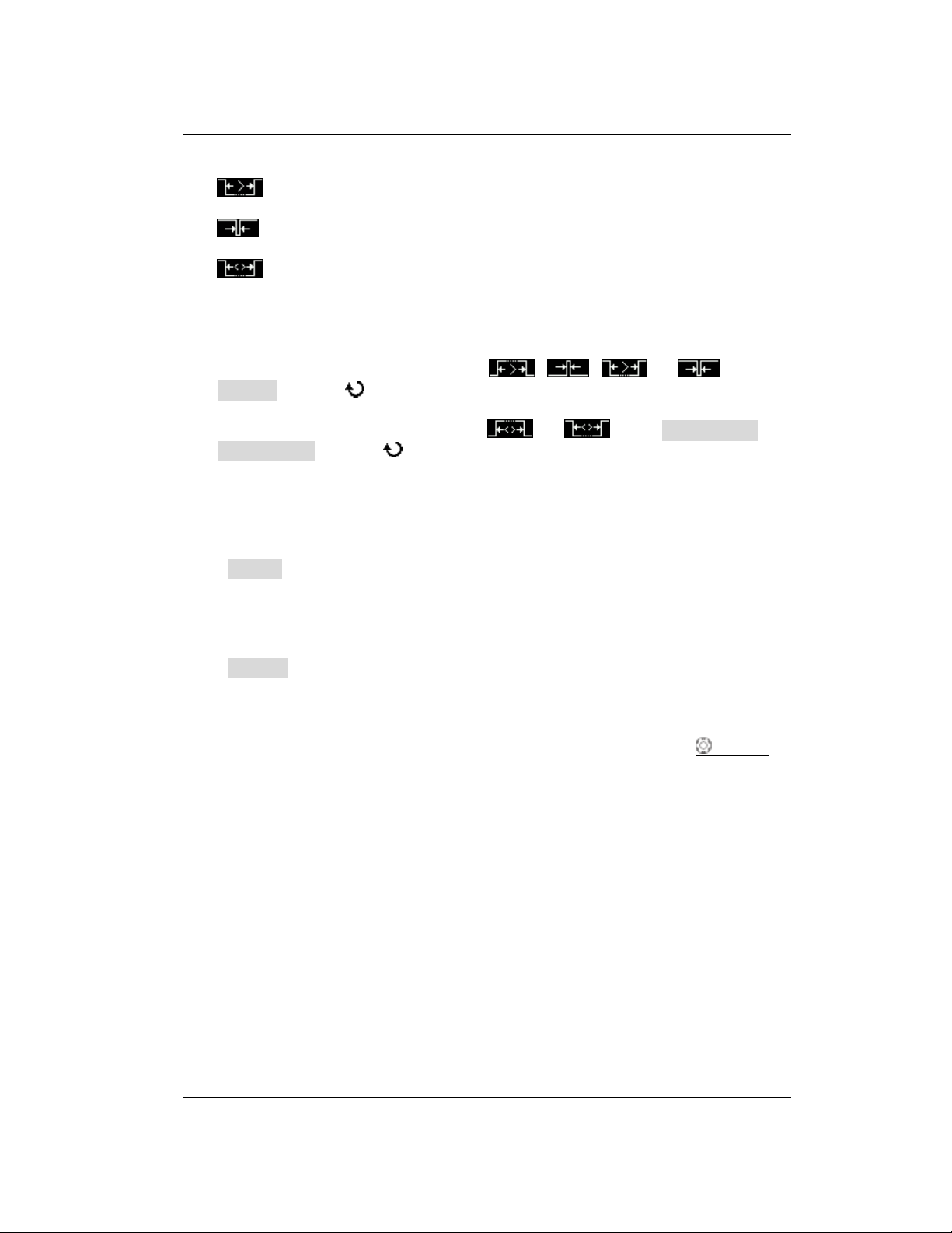
Chapter 5 To Trigger the Oscilloscope RIGOL
of pulse width.
: trigger when the negative pulse width of the input signal is greater than
the specified pulse width.
: trigger when the negative pulse width of the input signal is lower than
the specified pulse width.
: trigger when the negative pulse width of the input signal is greater than
the specified lower limit of pulse width and lower than the specified upper limit
of pulse width.
Pulse Width Setting:
When the Pulse Condition is set to , , or , press
Setting and use to input the desired value. The range available is from 8 ns
to 10 s.
When the Pulse Condition is set to or , press Upper Limit and
Lower Limit and use to input the desired values respectively. The range of
the upper limit is from 16 ns to 10 s. The range of the lower limit is from 8 ns to
9.99 s.
Note: The lower limit of the pulse width must be lower than the upper limit.
Trigger Mode:
Press Sweep to open the trigger mode list and select auto, normal or single. For the
details, please refer to "Trigger Mode". The corresponding status light of the
current trigger mode turns on.
Trigger Setting:
Press Setting to set the trigger parameters (trigger holdoff and noise rejection)
under this trigger type.
Trigger Level:
When the trigger source is an analog channel, you can use TRIGGER LEVEL to
modify the level. For the details, please refer to the introduction of "Trigger Level".
DS1000Z-E User Guide 5-9
Find Quality Products Online at: [email protected]
www.GlobalTestSupply.com
Page 71
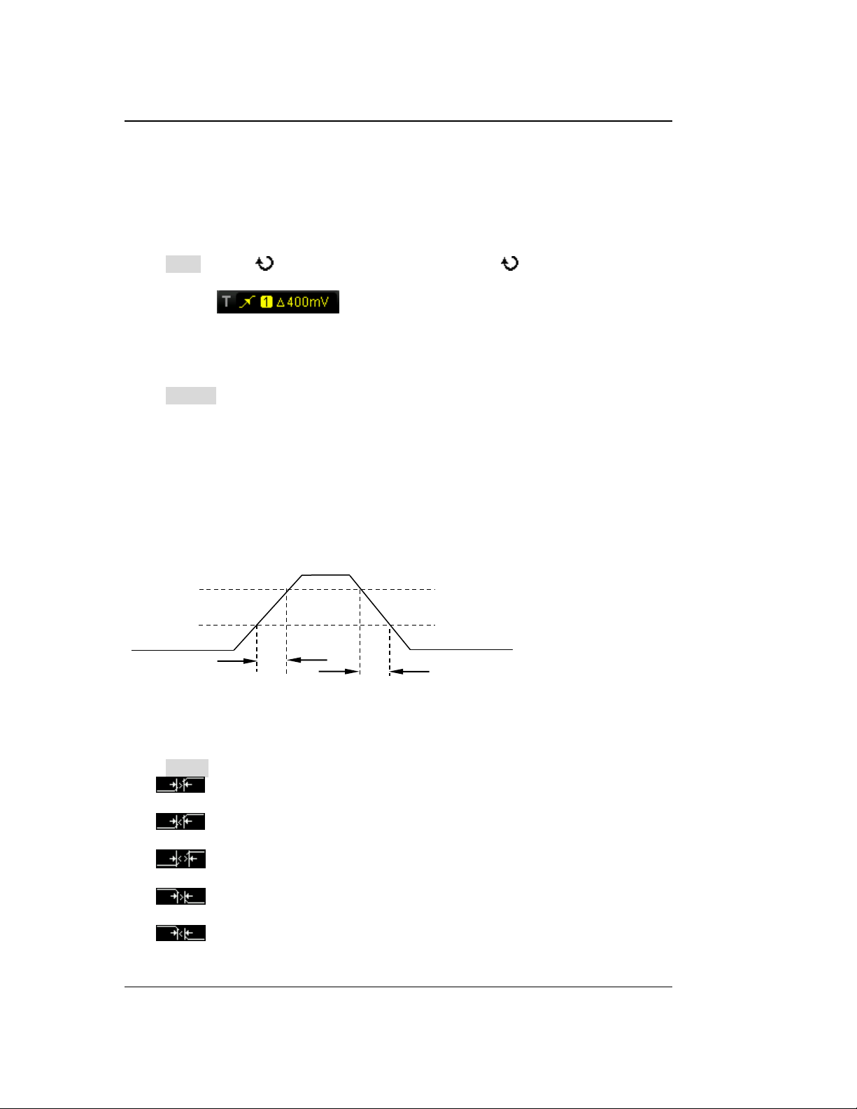
RIGOL Chapter 5 To Trigger the Oscilloscope
A
B
The upper limit of trigger level (Up Level)
The lower limit of trigger level (Low Level)
Positive
Slope Time
Negative
Slope Time
Slope Trigger
In slope trigger, the oscilloscope triggers on the positive or negative slope of the
specified time. This trigger mode is applicable to ramp and triangle waveforms.
Trigger Type:
Press Type, rotate to select "Slope" and press down . At this point, the
trigger setting information is displayed at the upper right corner of the screen.
For example, . The trigger type is slope trigger; the trigger source
is CH1; the difference between the upper limit of trigger level and the lower limit of
trigger level is 400 mV.
Source Selection:
Press Source to switch the signal source and select CH1 or CH2. For the details,
please refer to the introduction in "Trigger Source". The current trigger source is
displayed at the upper right corner of the screen.
Note: Select channel with signal input as trigger source to obtain stable trigger.
Slope Condition:
In this oscilloscope, positive slope time is defined as the time difference between the
two crossing points of trigger level line A and B with the rising edge; negative slope
time is defined as the time difference between the two crossing points of trigger level
line A and B with the falling edge as shown in the figure below.
Figure 5-4 Positive Slope Time/Negative Slope Time
Press When to select the desired slope condition.
: trigger when the positive slope time of the input signal is greater than
the specified time.
: trigger when the positive slope time of the input signal is lower than the
specified time.
: trigger when the positive slope time of the input signal is greater than
the specified lower limit of time and lower than the specified upper limit of time.
: trigger when the negative slope time of the input signal is greater than
the specified time.
: trigger when the negative slope time of the input signal is lower than
the specified time.
5-10 DS1000Z-E User Guide
Find Quality Products Online at: [email protected]
www.GlobalTestSupply.com
Page 72
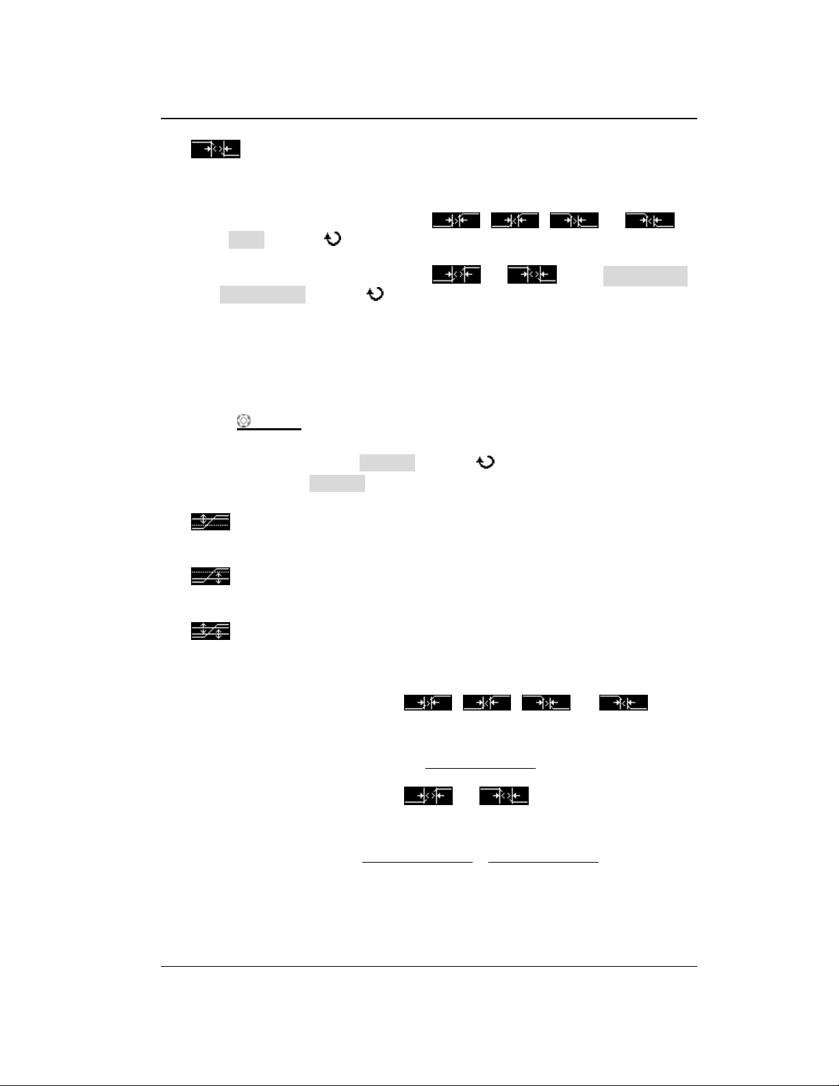
Chapter 5 To Trigger the Oscilloscope RIGOL
UpLevel - LowLevel
SlewRate=
Time
UpLevel - LowLevel UpLevel - LowLevel
SlewRate= ~
UpperLimit LowerLimit
: trigger when the negative slope time of the input signal is greater than
the specified lower limit of time and lower than the specified upper limit of time.
Time Setting:
When the Slope Condition is set to , , or ,
press Time and use to input the desired value. The range available is from 8
ns to 10 s.
When the Slope Condition is set to or , press Upper Limit
and Lower Limit and use to input the desired values respectively. The
range of time upper limit is from 16 ns to 10 s. The range of the time lower limit
is from 8 ns to 9.99 s.
Note: The time lower limit must be lower than the upper limit.
Vertical Window and Trigger Level:
After the trigger condition setting is completed, adjust the trigger level using
TRIGGER LEVEL to correctly trigger the signal and obtain stable waveform. The
adjustment mode of the trigger level is different when different vertical window is
selected in slope trigger. Press Vertical and use to select the desired vertical
window or press down Vertical continuously to switch the vertical window. You can
choose to only adjust the upper limit, the lower limit or both of them.
: only adjust the upper limit of the trigger level. During the adjustment,
"UP Level" and "Slew Rate" change accordingly but "Low Level" remains
unchanged.
: only adjust the lower limit of the trigger level. During the adjustment,
"Low Level" and "Slew Rate" change accordingly but "UP Level" remains
unchanged.
: adjust the upper and lower limits of the trigger level at the same time.
During the adjustment, "UP Level" and "Low Level" change accordingly but
"Slew Rate" remains unchanged.
When the Slope Condition is set to , , , or , the
current trigger level and slew rate will be displayed at the lower left corner of the
screen, as shown in figure 5-5 (a). The formula of slew rate is:
(5-1)
When the Slope Condition is set to or , the current trigger level
and slew rate range will be displayed at the lower left corner of the screen, as shown
in figure 5-5 (b). The formula of slew rate range is:
(5-2)
DS1000Z-E User Guide 5-11
Find Quality Products Online at: [email protected]
www.GlobalTestSupply.com
Page 73
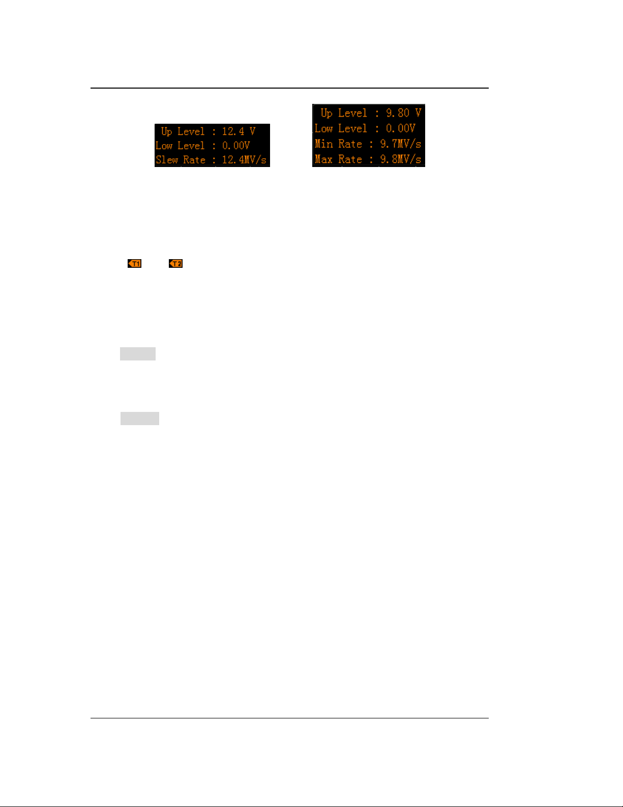
RIGOL Chapter 5 To Trigger the Oscilloscope
(a) (b)
Figure 5-5 Trigger Level Information Display
Note: Under the "Slope" trigger menu, you can also press down the trigger level
knob continuously to switch the vertical window.
During the adjustment of trigger level, two orange trigger level lines and two trigger
marks ( and ) appear on the screen and move up and down with the rotation
of the knob. At the same time, the current trigger level information is displayed at the
lower right corner of the screen according to different slope condition settings. After
stopping turning the knob, the trigger level lines and trigger level information
disappear in about 2 s.
Trigger Mode:
Press Sweep to open the trigger mode list and select auto, normal or single. For the
details, please refer to "Trigger Mode". The corresponding status light of the
current trigger mode turns on.
Trigger Setting:
Press Setting to set the trigger parameters (trigger holdoff and noise rejection)
under this trigger type.
5-12 DS1000Z-E User Guide
Find Quality Products Online at: [email protected]
www.GlobalTestSupply.com
Page 74
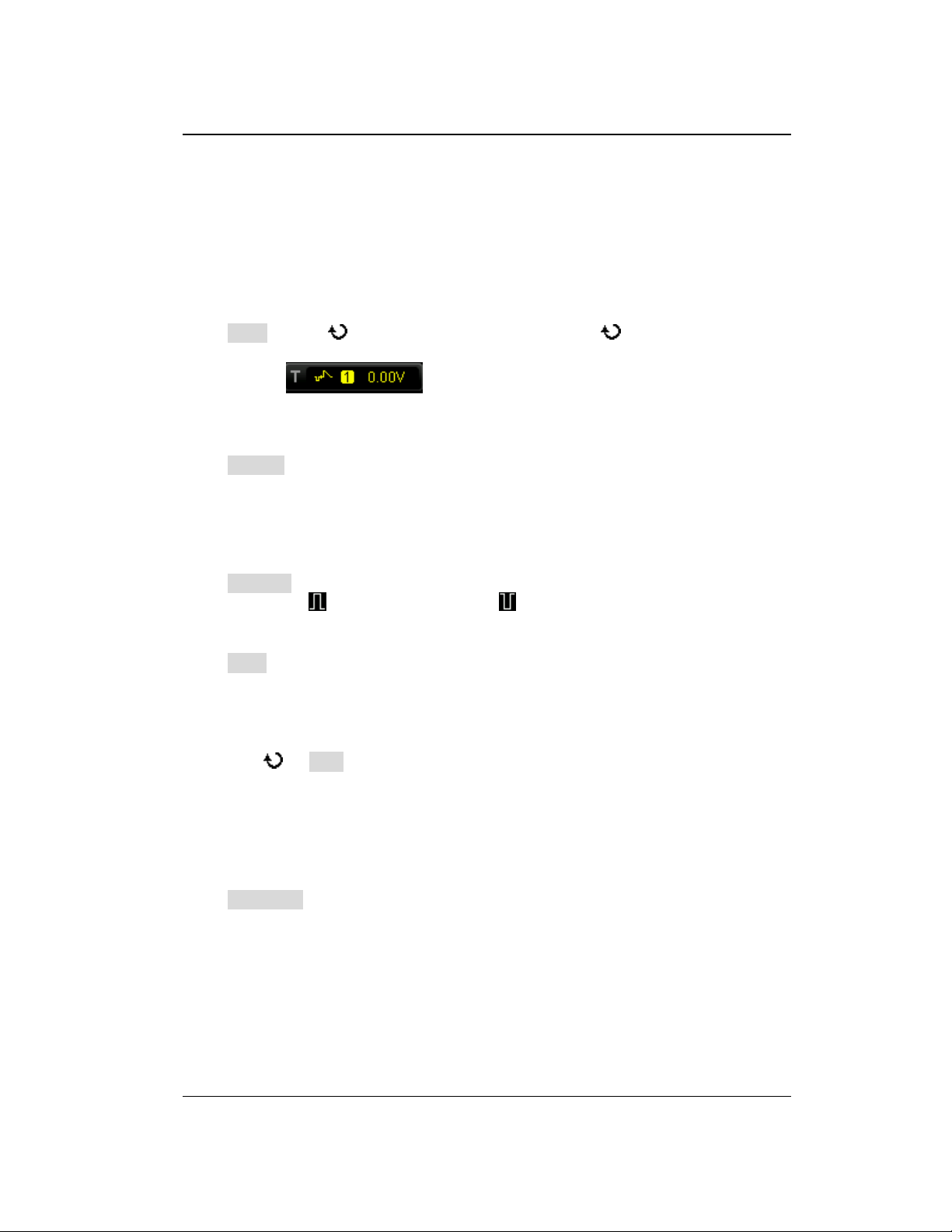
Chapter 5 To Trigger the Oscilloscope RIGOL
Video Trigger
The video signal can include image information and timing information and can
adopt different standards and formats. DS1000Z-E can trigger on the standard video
signal field or line of NTSC (National Television Standards Committee), PAL (Phase
Alternating Line) or SECAM (Sequential Couleur A Memoire).
Trigger Type:
Press Type, rotate to select "Video" and press down . At this point, the
trigger setting information is displayed at the upper right corner of the screen.
For example, . The trigger type is video trigger; the trigger
source is CH1; the trigger level is 0.00 V.
Source Selection:
Press Source to switch the signal source and select CH1 or CH2. For the details,
please refer to the introduction in "Trigger Source". The current trigger source is
displayed at the upper right corner of the screen.
Note: Select channel with signal input as trigger source to obtain stable trigger.
Video Polarity:
Press Polarity to select the desired video polarity. The polarities available are
positive polarity ( ) and negative polarity ( ).
Sync:
Press Sync to select the desired sync type.
All Line: trigger on the first line found.
Line: for NTSC and PAL/SECAM video standards, trigger on the specified line in
the odd or even field.
Note: When this sync trigger mode is selected, you can modify the line number
using in Line menu with a step of 1.
The range of the line number is from 1 to 525 (NTSC), 1 to 625 (PAL/SECAM), 1
to 525 (480P) or 1 to 625 (576P).
Odd: trigger on the rising edge of the first ramp pulse in the odd field.
Even: trigger on the rising edge of the first ramp pulse in the even field.
Video Standard:
Press Standard to select the desired video standard.
NTSC: the field frequency is 60 fields per second and the frame frequency is 30
frames per second. The TV scan line is 525 with the even field goes first and the
odd field follows behind.
PAL/SECAM:
--PAL: the frame frequency is 25 frames per second. The TV scan line is 625 with
the odd field goes first and the even field follows behind.
--SECAM: the frame frequency is 25 frames per second. The TV scan line is 625
with interlaced scan.
DS1000Z-E User Guide 5-13
Find Quality Products Online at: [email protected]
www.GlobalTestSupply.com
Page 75
RIGOL Chapter 5 To Trigger the Oscilloscope
Tips
For a better observation of the waveform details in the video signal, you can
set a larger memory depth first.
In the trigger debugging process of video signals, the frequency in different
part of the signal can be reflected by different brightness as RIGOL digital
oscilloscope provides the intensity graded color display function. Experienced
users can quickly judge the signal quality and discover abnormalities.
480P: the frame frequency is 60 frames per second; the TV scan line is 525;
progressive scan; the line frequency is 31.5 kHz.
576P: the frame frequency is 60 frames per second; the TV scan line is 625;
progressive scan.
Trigger Mode:
Press Sweep to open the trigger mode list and select auto, normal or single. For the
details, please refer to "Trigger Mode". The corresponding status light of the
current trigger mode turns on.
Trigger Setting:
Press Setting to set the trigger parameter (noise rejection) under this trigger type.
Trigger Level:
Use TRIGGER LEVEL to modify the level. For the details, please refer to the
introduction of "Trigger Level".
5-14 DS1000Z-E User Guide
Find Quality Products Online at: [email protected]
www.GlobalTestSupply.com
Page 76
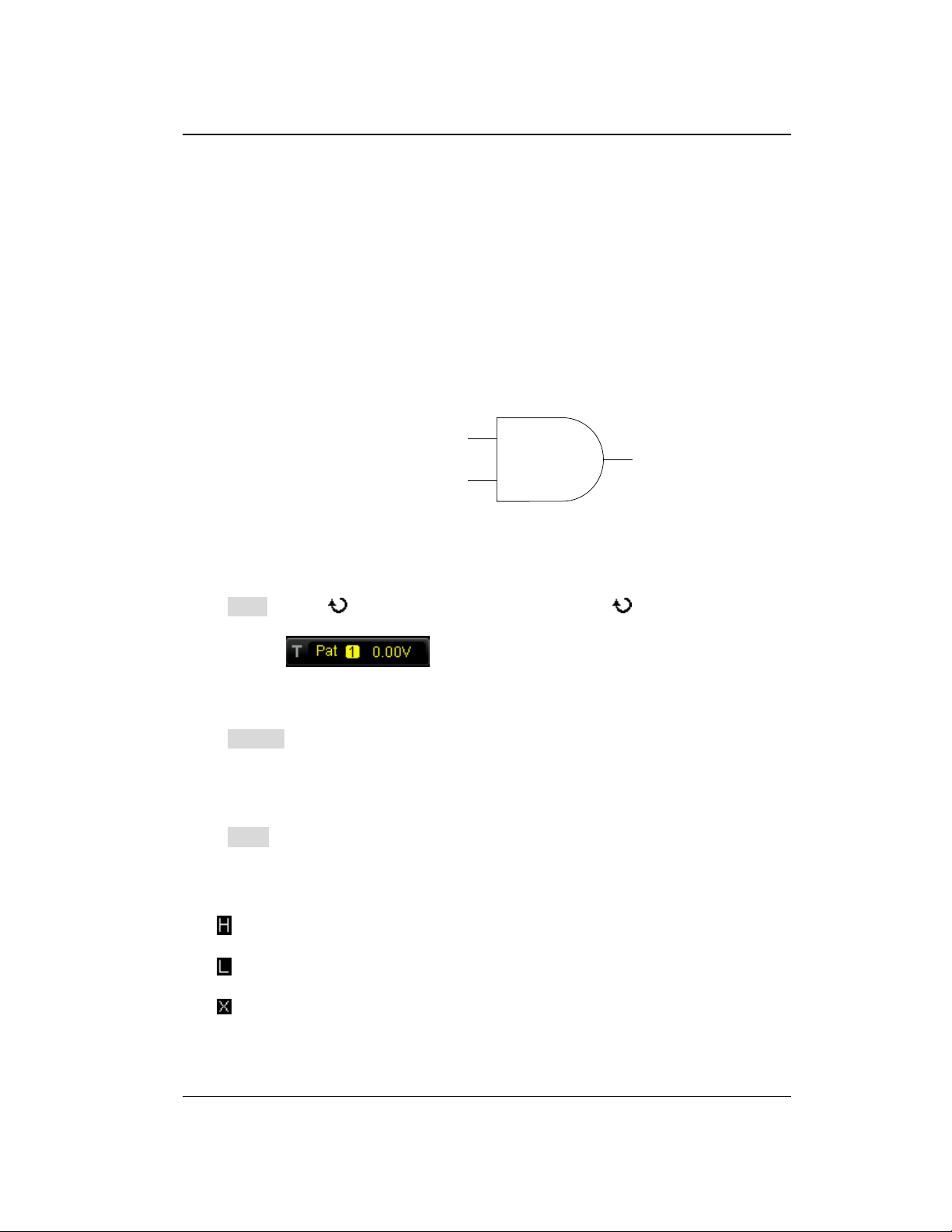
Chapter 5 To Trigger the Oscilloscope RIGOL
…
L
H
(CH1 or CH2)
…
(CH1 or CH2)
Pattern Trigger
Identify a trigger condition by looking for a specified pattern. This pattern is a logical
"AND" combination of channels. Each channel can have a value of high (H), low (L)
or don't care (X). A rising or falling edge (you can only specify a single edge) can be
specified for one channel included in the pattern. When an edge is specified, the
oscilloscope will trigger at the edge specified if the pattern set for the other channels
are true (namely the actual pattern of the channel is the same with the preset
pattern). If no edge is specified, the oscilloscope will trigger on the last edge that
makes the pattern true. If all the channels in the pattern are set to "Don’t Care", the
oscilloscope will not trigger.
Figure 5-6 Pattern Trigger
Trigger Type:
Press Type, rotate to select "Pattern" and press down . At this point, the
trigger setting information is displayed at the upper right corner of the screen.
For example, . The trigger type is pattern trigger; the current
trigger source is CH1; the trigger level is 0.00 V.
Source Selection:
Press Source to open the signal source list and select CH1 or CH2. For the details,
please refer to the introduction in "Trigger Source". The current trigger source is
displayed at the upper right corner of the screen.
Pattern Setting:
Press Code to set the pattern of the current signal source. At this point, the
corresponding pattern is displayed at the bottom of the screen. The patterns of
channels CH1 and CH2 are presented from left to right as shown in the figure below.
: set the pattern of the channel selected to "H", namely the voltage level is
higher than the trigger level of the channel.
: set the pattern of the channel selected to "L", namely the voltage level is
lower than the trigger level of the channel.
: set the pattern of the channel selected to "Don’t Care", namely this channel
is not used as a part of the pattern. When all channels in the pattern are set to
"Don’t Care", the oscilloscope will not trigger.
DS1000Z-E User Guide 5-15
Find Quality Products Online at: [email protected]
www.GlobalTestSupply.com
Page 77
RIGOL Chapter 5 To Trigger the Oscilloscope
or : set the pattern to the rising or falling edge of the channel selected.
Note:
Only one edge (rising or falling edge) can be specified in the pattern. If one edge
item is currently defined and then another edge item is defined in another channel in
the pattern, the former edge item defined will be replaced by X.
All Bits:
Press AllBits to set the patterns of all trigger sources to the pattern settings selected
currently.
Trigger Mode:
Press Sweep to open the trigger mode list and select auto, normal or single. For the
details, please refer to "Trigger Mode". The corresponding status light of the
current trigger mode turns on.
Trigger Setting:
Press Setting to set the trigger parameters (trigger holdoff and noise rejection)
under this trigger type.
Trigger Level:
For the analog channels, the trigger level of each channel needs to be set
independently. For example, set the trigger level of CH1. Press Source to select CH1,
and then use TRIGGER LEVEL to modify the level. For the details, please refer
to the introduction of "Trigger Level".
5-16 DS1000Z-E User Guide
Find Quality Products Online at: [email protected]
www.GlobalTestSupply.com
Page 78
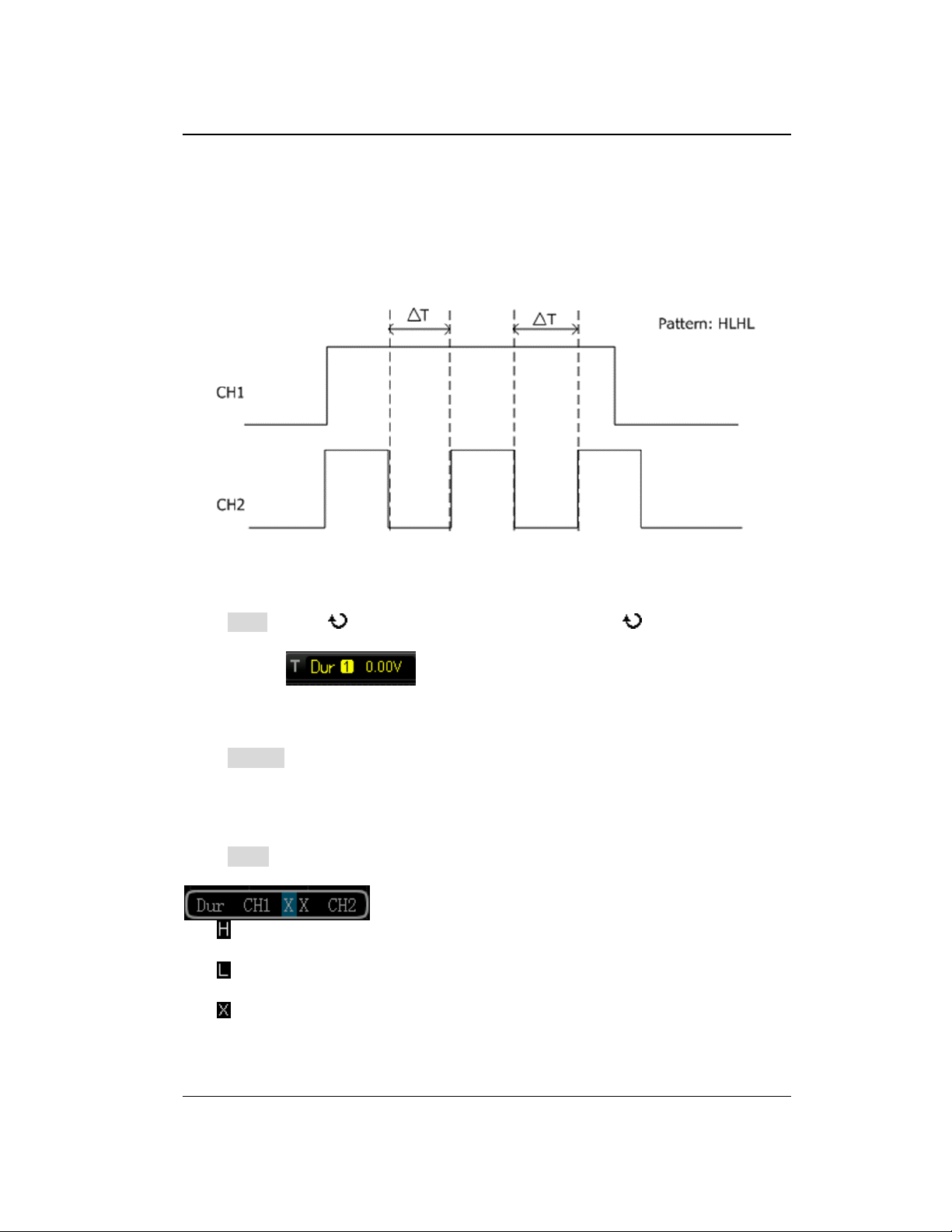
Chapter 5 To Trigger the Oscilloscope RIGOL
Duration Trigger
In duration trigger, the instrument identifies a trigger condition by looking for the
duration of a specified pattern. This pattern is a logical "AND" combination of the
channels. Each channel can have a value of high (H), low (L) or don’t care (X). The
instrument triggers when the duration (△T) of this pattern meets the preset time, as
shown in the figure below.
Figure 5-7 Duration Trigger
Trigger Type:
Press Type, rotate to select "Duration" and press down . At this point, the
trigger setting information is displayed at the upper right corner of the screen.
For example, . The trigger type is duration trigger; the current
trigger source is CH1; the trigger level is 0.00 V.
Source Selection:
Press Source to open the signal source list and select CH1 or CH2. For the details,
please refer to the introduction in "Trigger Source". The current trigger source is
displayed at the upper right corner of the screen.
Pattern Setting:
Press Code to set the pattern of the current channel. At this point, the pattern
setting area (as shown in the figure below) is displayed at the bottom of the screen.
: set the pattern of the channel selected to "H", namely the voltage level is
higher than the trigger level of the channel.
: set the pattern of the channel selected to "L", namely the voltage level is
lower than the trigger level of the channel.
: set the pattern of the channel selected to "Don’t Care", namely this channel
is not used as a part of the pattern. When all channels in the pattern are set to
"Don’t Care", the oscilloscope will not trigger.
DS1000Z-E User Guide 5-17
Find Quality Products Online at: [email protected]
www.GlobalTestSupply.com
Page 79
RIGOL Chapter 5 To Trigger the Oscilloscope
All Bits:
Press AllBits to set the patterns of all trigger sources to the pattern settings selected
currently.
Trigger Condition:
Press When to select the desired trigger condition.
>: trigger when the duration of the pattern is greater than the preset time.
Press Time to set the duration of the pattern and the range is from 8 ns to 10 s.
<: trigger when the duration of the pattern is lower than the preset time. Press
Time to set the duration of the pattern and the range is from 8 ns to 10 s.
<>: trigger when the duration of the pattern is lower than the upper limit of the
preset time and greater than the lower limit of the preset time. Press Upper
Limit to set the upper limit of the duration of the pattern and the range is from
16 ns to 10 s. Press Lower Limit to set the lower limit of the duration of the
pattern and the range is from 8 ns to 9.99 s.
Note: The time lower limit must be lower than the time upper limit.
Trigger Mode:
Press Sweep to open the trigger mode list and select auto, normal or single. For the
details, please refer to "Trigger Mode". The corresponding status light of the
current trigger mode turns on.
Trigger Setting:
Press Setting to set the trigger parameters (trigger holdoff and noise rejection)
under this trigger type.
Trigger Level:
Press Source to select CH1 to CH2 respectively; use TRIGGER LEVEL to modify
the trigger level for each channel. For the details, please refer to the introduction of
"Trigger Level".
5-18 DS1000Z-E User Guide
Find Quality Products Online at: [email protected]
www.GlobalTestSupply.com
Page 80
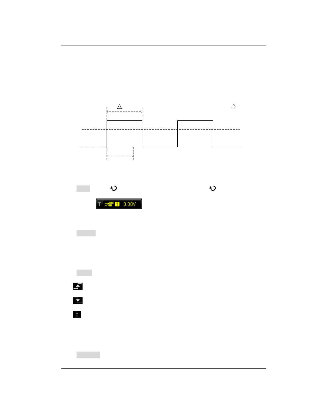
Chapter 5 To Trigger the Oscilloscope RIGOL
Time Out
T
Time Out< T
TimeOut Trigger
In timeout trigger, the instrument triggers when the time interval (△T) from when
the rising edge (or falling edge) of the input signal passes through the trigger level to
when the neighbouring falling edge (or rising edge) passes through the trigger level
is greater than the timeout time set, as shown in the figure below.
Figure 5-8 TimeOut Trigger
Trigger Type:
Press Type, rotate to select "TimeOut" and press down . At this point, the
trigger setting information is displayed at the upper right corner of the screen.
For example, . The trigger type is timeout trigger; the trigger
source is CH1; the trigger level is 0.00 V.
Source Selection:
Press Source to open the signal source list and select CH1 or CH2. For the details,
please refer to the introduction in "Trigger Source". The current trigger source is
displayed at the upper right corner of the screen.
Note: Select channel with signal input as trigger source to obtain stable trigger.
Edge Type:
Press Slope to select the type of the first edge of the input signal that passes
through the trigger level.
: start timing when the rising edge of the input signal passes through the
trigger level.
: start timing when the falling edge of the input signal passes through the
trigger level.
: start timing when any edge of the input signal passes through the trigger
level.
Timeout Time:
Timeout time represents the minimum time that the clock signal must be in the idle
state before the oscilloscope starts searching for the data meets the trigger condition.
Press TimeOut to set the timeout time of timeout trigger and the range is from 16
DS1000Z-E User Guide 5-19
Find Quality Products Online at: [email protected]
www.GlobalTestSupply.com
Page 81
RIGOL Chapter 5 To Trigger the Oscilloscope
ns to 10 s.
Trigger Mode:
Press Sweep to open the trigger mode list and select auto, normal or single. For the
details, please refer to "Trigger Mode". The corresponding status light of the
current trigger mode turns on.
Trigger Setting:
Press Setting to set the trigger parameter (noise rejection) under this trigger type.
Trigger Level:
When the trigger source is an analog channel, you can use TRIGGER LEVEL to
modify the level. For the details, please refer to the introduction of "Trigger Level".
5-20 DS1000Z-E User Guide
Find Quality Products Online at: [email protected]
www.GlobalTestSupply.com
Page 82
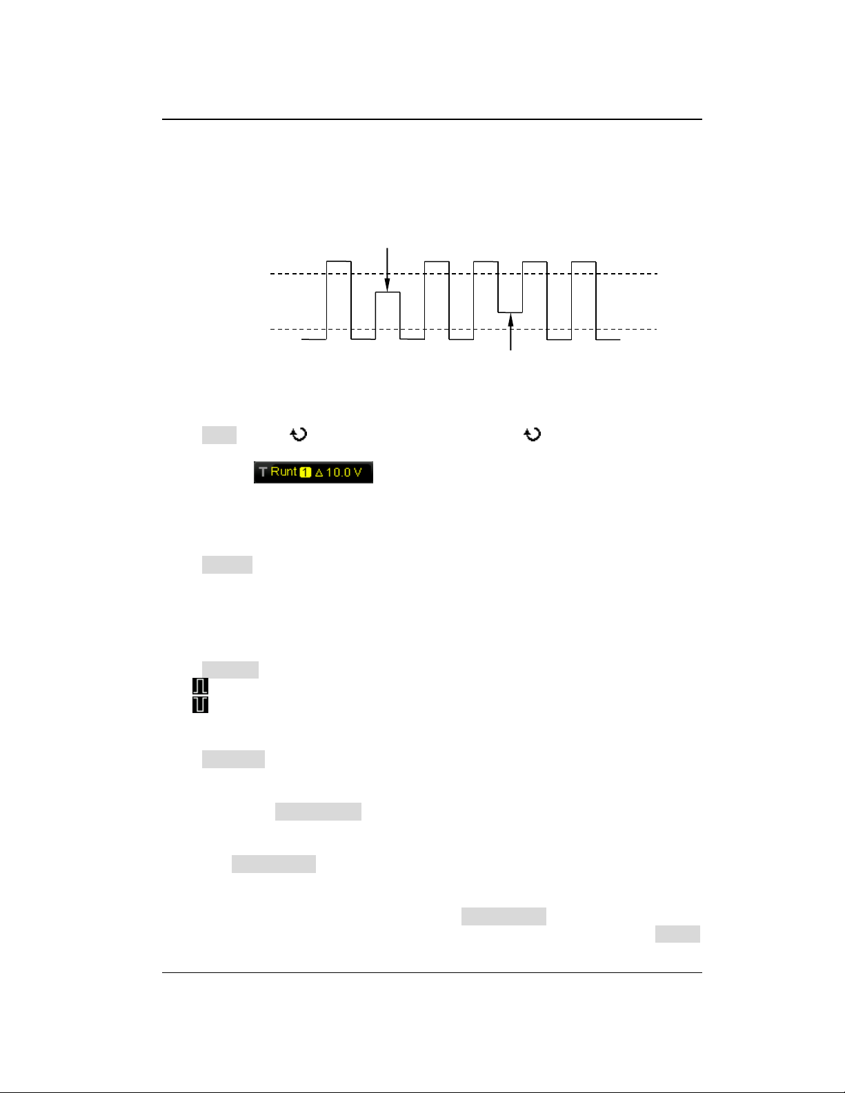
Chapter 5 To Trigger the Oscilloscope RIGOL
Upper Limit of the
Trigger Level
Lower Limit of the
Trigger Level
Positive Runt Pulse
Negative Runt Pulse
Runt Trigger
This trigger mode is used to trigger pulses that pass through one trigger level but fail
to pass through the other trigger level as shown in the figure below.
Figure 5-9 Runt Trigger
Trigger Type:
Press Type, rotate to select "Runt" and press down . At this point, the trigger
setting information is displayed at the upper right corner of the screen.
For example, . The trigger type is runt trigger; the trigger source
is CH1; the difference between the upper limit of trigger level and the lower limit of
trigger level is 10.00 V.
Source Selection:
Press Source to switch the signal source and select CH1 or CH2. For the details,
please refer to the introduction in "Trigger Source". The current trigger source is
displayed at the upper right corner of the screen.
Note: Select channel with signal input as trigger source to obtain stable trigger.
Pulse Polarity:
Press Polarity to select the pulse polarity of runt trigger.
: positive polarity. The instrument triggers on the positive runt pulse.
: negative polarity. The instrument triggers on the negative runt pulse.
Qualifier:
Press Qualifier to set the trigger conditions of runt trigger.
None: do not set the trigger condition of runt trigger.
>: trigger when the runt pulse width is greater than the lower limit of pulse
width. Press Lower Limit to set the minimum pulse width of runt trigger. The
range available is from 8.00 ns to 10 s.
<: trigger when the runt pulse width is lower than the upper limit of pulse width.
Press Upper Limit to set the maximum pulse width of runt trigger. The range
available is from 16.0 ns to 10.0 s.
<>: trigger when the runt pulse width is greater than the lower limit and lower
than the upper limit of pulse width. Press Upper Limit to set the maximum
pulse width of runt trigger and the range is from 16.0 ns to 10.0 s; press Lower
DS1000Z-E User Guide 5-21
Find Quality Products Online at: [email protected]
www.GlobalTestSupply.com
Page 83
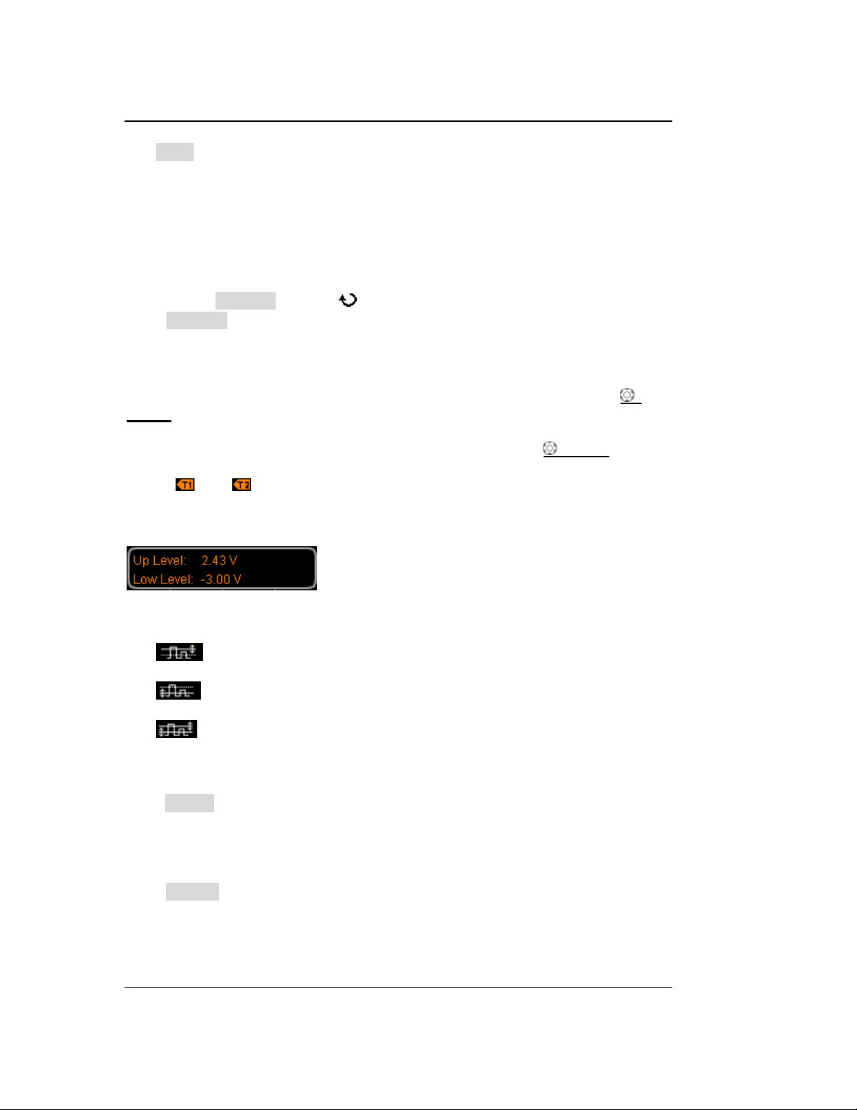
RIGOL Chapter 5 To Trigger the Oscilloscope
Limit to set the minimum pulse width of runt trigger and the range is from 8.00
ns to 9.99 s.
Note: The lower limit of the pulse width must be lower than the upper limit.
Vertical Window and Trigger Level:
After the trigger condition setting is completed, you need to adjust the trigger level
to correctly trigger the signal and obtain stable waveform. The adjustment mode of
the trigger level is different when different vertical window is selected in the runt
trigger. Press Window and use to select the desired vertical window or press
down Window continuously to switch the vertical window. You can choose to only
adjust the upper limit, the lower limit or both of them. For more details, please refer
to the following introduction.
Note: Under the "Runt" trigger menu, you can also press down TRIGGER
LEVEL continuously to switch the vertical window.
After the vertical window type is selected, you can use Trigger LEVEL to adjust
the trigger level. During the adjustment, two orange trigger level lines and trigger
marks ( and ) appear on the screen and move up and down with the rotation
of the knob. At the same time, the current trigger level values are displayed at the
lower left corner of the screen (as shown in the figure below). The trigger level lines
and trigger marks disappear after you stop rotating the knob for about 2 s.
The adjustment mode of the trigger level differs when different vertical window is
selected.
: only adjust the upper limit of the trigger level. During the adjustment,
the "Up Level" changes accordingly and "Low Level" remains unchanged.
: only adjust the lower limit of the trigger level. During the adjustment,
the "Low Level" changes accordingly and the "Up Level" remains unchanged.
: adjust the upper and lower limits of the trigger level at the same time.
During the adjustment, the "Up Level" and "Low Level" change accordingly.
Trigger Mode:
Press Sweep to open the trigger mode list and select auto, normal or single. For the
details, please refer to "Trigger Mode". The corresponding status light of the
current trigger mode turns on.
Trigger Setting:
Press Setting to set the trigger parameters (trigger holdoff and noise rejection)
under this trigger type.
5-22 DS1000Z-E User Guide
Find Quality Products Online at: [email protected]
www.GlobalTestSupply.com
Page 84
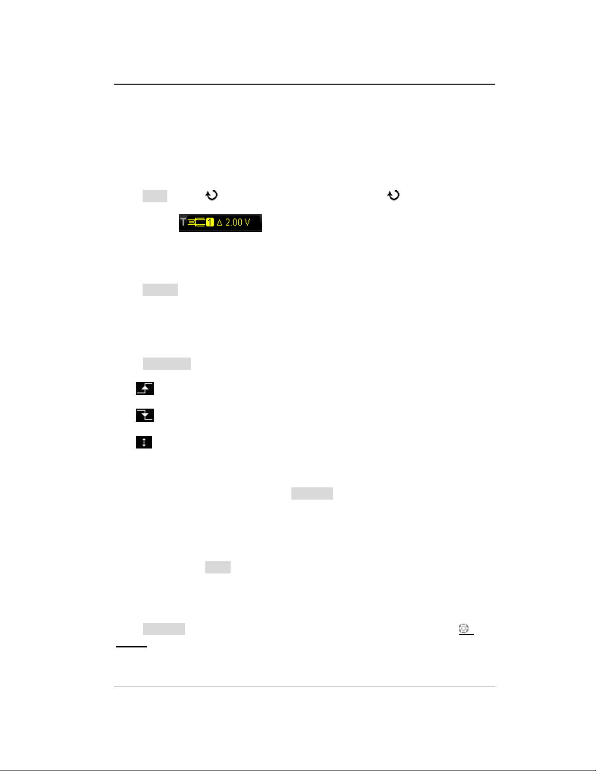
Chapter 5 To Trigger the Oscilloscope RIGOL
Window Trigger
Window trigger provides a high trigger level and a low trigger level. The instrument
triggers when the input signal passes through the high trigger level or the low trigger
level.
Trigger Type:
Press Type, rotate to select "Window" and press down . At this point, the
trigger setting information is displayed at the upper right corner of the screen.
For example, . The trigger type is window trigger; the trigger
source is CH1; the difference between the upper limit of trigger level and the lower
limit of trigger level is 2.00 V.
Source Selection:
Press Source to switch the trigger source and select CH1 or CH2. For the details,
please refer to the introduction in "Trigger Source". The current trigger source is
displayed at the upper right corner of the screen.
Note: Select channel with signal input as trigger source to obtain stable trigger.
Window Type:
Press WndType to select the kind of edge of the input signal on which the
oscilloscope triggers.
: trigger on the rising edge of the input signal when the voltage level is
greater than the preset high trigger level.
: trigger on the falling edge of the input signal when the voltage level is
lower than the preset low trigger level.
: trigger on any edge of the input signal when the voltage level meets the
preset trigger level.
Trigger Position:
After selecting the window type, press Position to further specify the time point of
trigger by selecting the trigger position.
Enter: trigger when the trigger signal enters the specified trigger level range.
Exit: trigger when the input signal exits the specified trigger level range.
Time: trigger when the accumulated hold time after the trigger signal enters
the specified trigger level range is equal to the window time. When this type is
selected, press Time to set the window time. The range is from 8 ns to 10 s. For
the setting method, please refer to the introduction in "Parameter Setting
Method".
Vertical Window and Trigger Level:
Press Window to select the desired vertical window type and use Trigger
LEVEL to adjust the trigger level. For detailed operation, please refer to the
introduction in "Vertical Window and Trigger Level" in runt trigger.
DS1000Z-E User Guide 5-23
Find Quality Products Online at: [email protected]
www.GlobalTestSupply.com
Page 85
RIGOL Chapter 5 To Trigger the Oscilloscope
Trigger Mode:
Press Sweep to open the trigger mode list and select auto, normal or single. For the
details, please refer to "Trigger Mode". The corresponding status light of the
current trigger mode turns on.
Trigger Setting:
Press Setting to set the trigger parameters (trigger holdoff and noise rejection)
under this trigger type.
5-24 DS1000Z-E User Guide
Find Quality Products Online at: [email protected]
www.GlobalTestSupply.com
Page 86
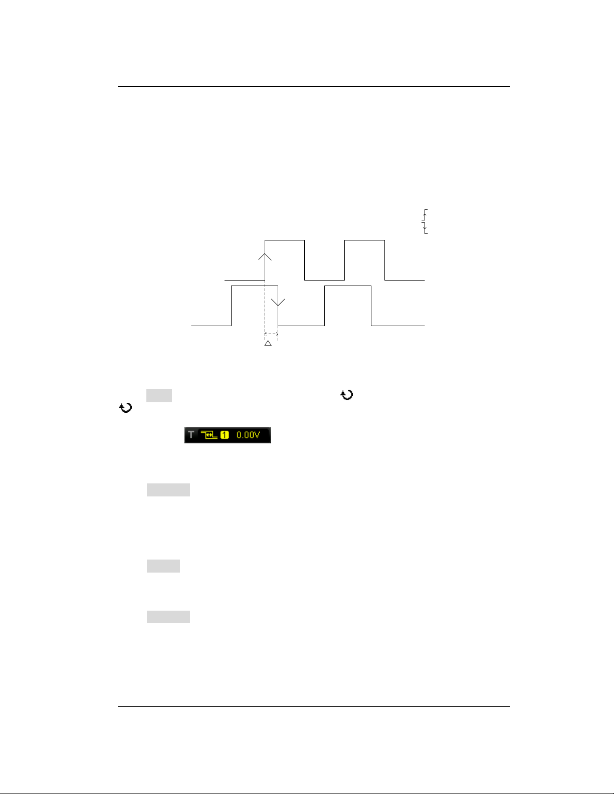
Chapter 5 To Trigger the Oscilloscope RIGOL
T
Source A
Source B
Edge A=
Edge B=
Delay Trigger
In delay trigger, you need to set signal source A and signal source B. The oscilloscope
triggers when the time difference (△T) between the specified edges of source A
(Edge A) and source B (Edge B) meets the preset time limit, as shown in the figure
below.
Note: Edge A and Edge B must be neighbouring edges.
Figure 5-10 Delay Trigger
Trigger Type:
Press Type to open the trigger type list. Rotate to select "Delay" and press down
. At this point, the trigger setting information is displayed at the upper right corner
of the screen.
For example, . The trigger type is delay trigger; the current
trigger source is CH1; the trigger level is 0.00 V.
Source A:
Press SourceA to select CH1 or CH2 as the trigger source of signal source A. For the
details, please refer to the introduction in "Trigger Source". The current trigger
source is displayed at the upper right corner of the screen.
Note: Select channel with signal input as trigger source to obtain stable trigger.
Edge A:
Press EdgeA to select the trigger edge type of signal source A in delay trigger. It can
be set to the rising edge or falling edge.
Source B:
Press SourceB to select CH1 or CH2 as the trigger source of signal source B. For the
details, please refer to the introduction in "Trigger Source". The current trigger
source is displayed at the upper right corner of the screen.
Note: Select channel with signal input as trigger source to obtain stable trigger.
DS1000Z-E User Guide 5-25
Find Quality Products Online at: [email protected]
www.GlobalTestSupply.com
Page 87
RIGOL Chapter 5 To Trigger the Oscilloscope
Edge B:
Press EdgeB to select the trigger edge type of signal source B in delay trigger. It can
be set to the rising edge or falling edge.
Delay Type:
Press DelayType to set the time limit condition of delay trigger.
>: trigger when the time difference (△T) between the specified edges of source
A and source B is greater than the preset time lower limit. Press Lower Limit to
set the delay time lower limit in delay trigger and the range is from 8.00 ns to 10
s. For the setting method, please refer to the introduction in "Parameter
Setting Method".
<: trigger when the time difference (△T) between the specified edges of source
A and source B is lower than the preset time upper limit. Press Upper Limit to
set the delay time upper limit in delay trigger and the range is from 16.0 ns to
10.0 s. For the setting method, please refer to the introduction in "Parameter
Setting Method".
<>: trigger when the time difference (△T) between the specified edges of
source A and source B is greater than the lower limit of the preset time and
lower than the upper limit of the preset time. Press Upper Limit to set the
upper limit of the delay time in delay trigger and the range is from 16.0 ns to
10.0 s. Press Lower Limit to set the lower limit of the delay time in delay
trigger and the range is from 8.00 ns to 9.99 s. For the setting method, please
refer to the introduction in "Parameter Setting Method".
Note: The time lower limit must be lower than the time upper limit.
><: trigger when the time difference (△T) between the specified edges of
source A and source B is lower than the lower limit of the preset time or greater
than the upper limit of the preset time. Press Upper Limit to set the upper limit
of the delay time in delay trigger and the range is from 16.0 ns to 10.0 s. Press
Lower Limit to set the lower limit of the delay time in delay trigger and the
range is from 8.00 ns to 9.99 s. For the setting method, please refer to the
introduction in "Parameter Setting Method".
Note: The time lower limit must be lower than the time upper limit.
Trigger Mode:
Press Sweep to open the trigger mode list and select auto, normal or single. For the
details, please refer to "Trigger Mode". The corresponding status light of the
current trigger mode turns on.
Trigger Setting:
Press Setting to set the trigger parameters (trigger holdoff and noise rejection)
under this trigger type.
Trigger Level:
The trigger level of each source needs to be set independently. For example, set the
trigger level of source A. Press SourceA to select the desired source, and then use
5-26 DS1000Z-E User Guide
Find Quality Products Online at: [email protected]
www.GlobalTestSupply.com
Page 88
Chapter 5 To Trigger the Oscilloscope RIGOL
TRIGGER LEVEL to modify the level. For the details, please refer to the
introduction of "Trigger Level".
DS1000Z-E User Guide 5-27
Find Quality Products Online at: [email protected]
www.GlobalTestSupply.com
Page 89
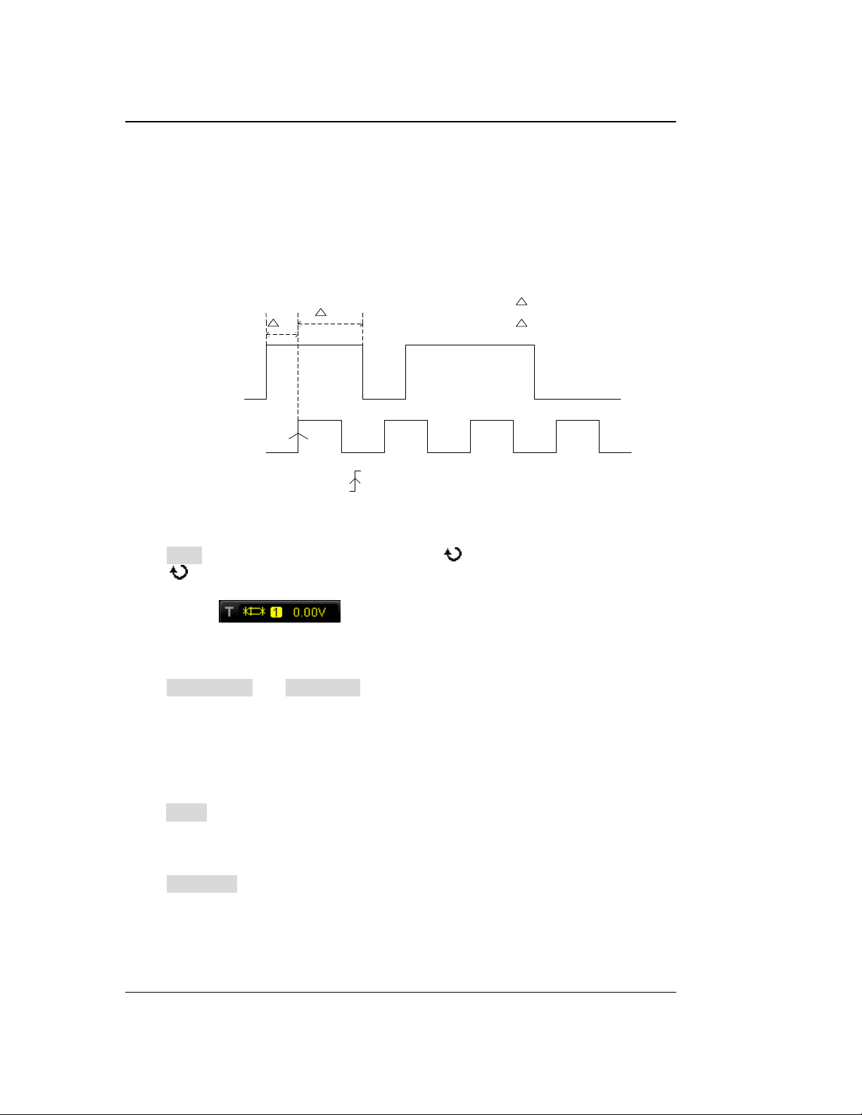
RIGOL Chapter 5 To Trigger the Oscilloscope
T1
T2
Data Source
Clock Source
T2
T1
is the setup time
is the hold time
The edge type is
The data type is H
Setup/Hold Trigger
In setup/hold trigger, you need to set the data signal line and clock signal line. The
setup time starts when the data signal passes the trigger level and ends at the
coming of the specified clock edge; the hold time starts at the coming of the
specified clock edge and ends when the data signal passes the trigger level again (as
shown in the figure below). The oscilloscope triggers when the setup time or hold
time is lower than the preset time.
Figure 5-11 Setup/Hold Trigger
Trigger Type:
Press Type to open the trigger type list. Rotate to select "StpHold" and press
down . At this point, the trigger setting information is displayed at the upper right
corner of the screen.
For example, . The trigger type is setup/hold trigger; the current
trigger source is CH1; the trigger level is 0.00 V.
Source Selection:
Press DataSource and ClkSource to set the signal sources of the data line and
clock line respectively. They can be set to CH1 or CH2. For the details, please refer to
the introduction in "Trigger Source". The current trigger source is displayed at the
upper right corner of the screen.
Note: Select channel with signal input as trigger source to obtain stable trigger.
Edge Type:
Press Slope to select the desired clock edge type and it can be set to the rising edge
or falling edge.
Data Type:
Press DataType to set the effective pattern of the data signal to H (high level) or L
(low level).
5-28 DS1000Z-E User Guide
Find Quality Products Online at: [email protected]
www.GlobalTestSupply.com
Page 90
Chapter 5 To Trigger the Oscilloscope RIGOL
Setup Type:
It is used to select the different trigger types of setup/hold trigger. Press SetupType
to select the desired setup type.
Setup: the oscilloscope triggers when the setup time is less than the specified
setup time. After selecting this type, press Setup to set the setup time and the
range is from 8 ns to 1 s.
Hold: the oscilloscope triggers when the hold time is less than the specified
hold time. After selecting this type, press Hold to set the hold time and the
range is from 8 ns to 1 s.
StpHold: the oscilloscope triggers when the setup time and hold time are less
than the specified times. After selecting this type, press Setup and Hold to set
the setup time and hold time respectively and the range is from 8 ns to 1 s.
Trigger Mode:
Press Sweep to open the trigger mode list and select auto, normal or single. For the
details, please refer to "Trigger Mode". The corresponding status light of the
current trigger mode turns on.
Trigger Setting:
Press Setting to set the trigger parameter (noise rejection) under this trigger type.
Trigger Level:
Press DataSource and use TRIGGER LEVEL to modify the trigger level of the
data source channel. Press ClkSource and use TRIGGER LEVEL to modify the
trigger level of the clock source channel. For the details, please refer to the
introduction of "Trigger Level".
DS1000Z-E User Guide 5-29
Find Quality Products Online at: [email protected]
www.GlobalTestSupply.com
Page 91
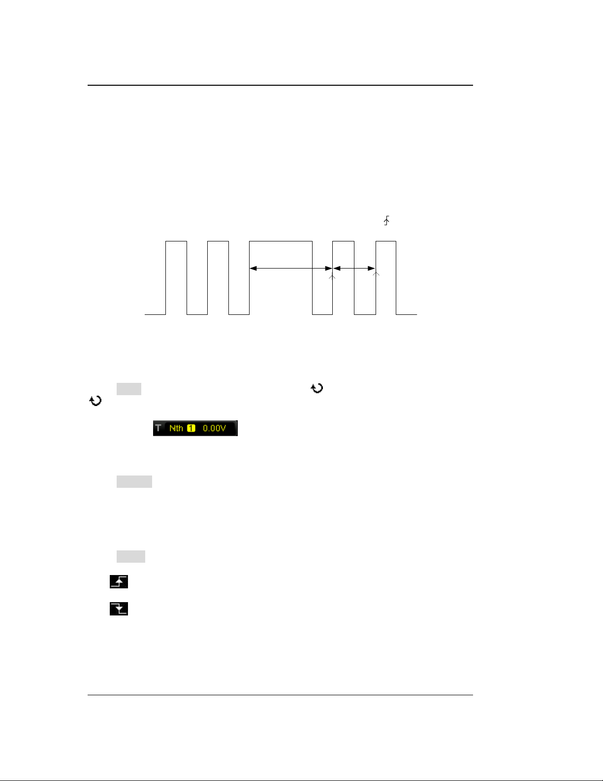
RIGOL Chapter 5 To Trigger the Oscilloscope
M
P<Idle Time<M
Edge Type=
Edge Num=2
P
Nth Edge Trigger
Trigger on the nth edge that appears after the specified idle time. For example, in the
waveform shown in the figure below, the instrument should trigger on the second
rising edge after the specified idle time (the time between two neighbouring rising
edges) and the idle time should be set to P<Idle Time<M. Wherein, M is the time
between the first rising edge and its previous rising edge and P is the maximum time
between the rising edges participate in the counting.
Figure 5-12 Nth Edge Trigger
Trigger Type:
Press Type to open the trigger type list. Rotate to select "Nth" and press down
. At this point, the trigger setting information is displayed at the upper right corner
of the screen.
For example, . The trigger type is Nth edge trigger; the trigger
source is CH1; the trigger level is 0.00 V.
Source Selection:
Press Source to open the signal source list and select CH1 or CH2. For the details,
please refer to the introduction in "Trigger Source". The current trigger source is
displayed at the upper right corner of the screen.
Note: Select channel with signal input as trigger source to obtain stable trigger.
Edge Type:
Press Slope to select the kind of edge of the input signal on which the oscilloscope
triggers.
: trigger on the rising edge of the input signal when the voltage level meets
the specified trigger level.
: trigger on the falling edge of the input signal when the voltage level meets
the specified trigger level.
5-30 DS1000Z-E User Guide
Find Quality Products Online at: [email protected]
www.GlobalTestSupply.com
Page 92
Chapter 5 To Trigger the Oscilloscope RIGOL
Idle Time:
Press Idle to set the idle time before the edge counting in Nth edge trigger. The
range available is from 16 ns to 10 s.
Edge Number:
Press Edge to set the value of "N" in Nth edge trigger and the range available is from
1 to 65535.
Trigger Mode:
Press Sweep to open the trigger mode list and select auto, normal or single. For the
details, please refer to "Trigger Mode". The corresponding status light of the
current trigger mode turns on.
Trigger Setting:
Press Setting to set the trigger parameter (noise rejection) under this trigger type.
Trigger Level:
When the trigger source is an analog channel, you can use TRIGGER LEVEL to
modify the level. For the details, please refer to the introduction of "Trigger Level".
DS1000Z-E User Guide 5-31
Find Quality Products Online at: [email protected]
www.GlobalTestSupply.com
Page 93
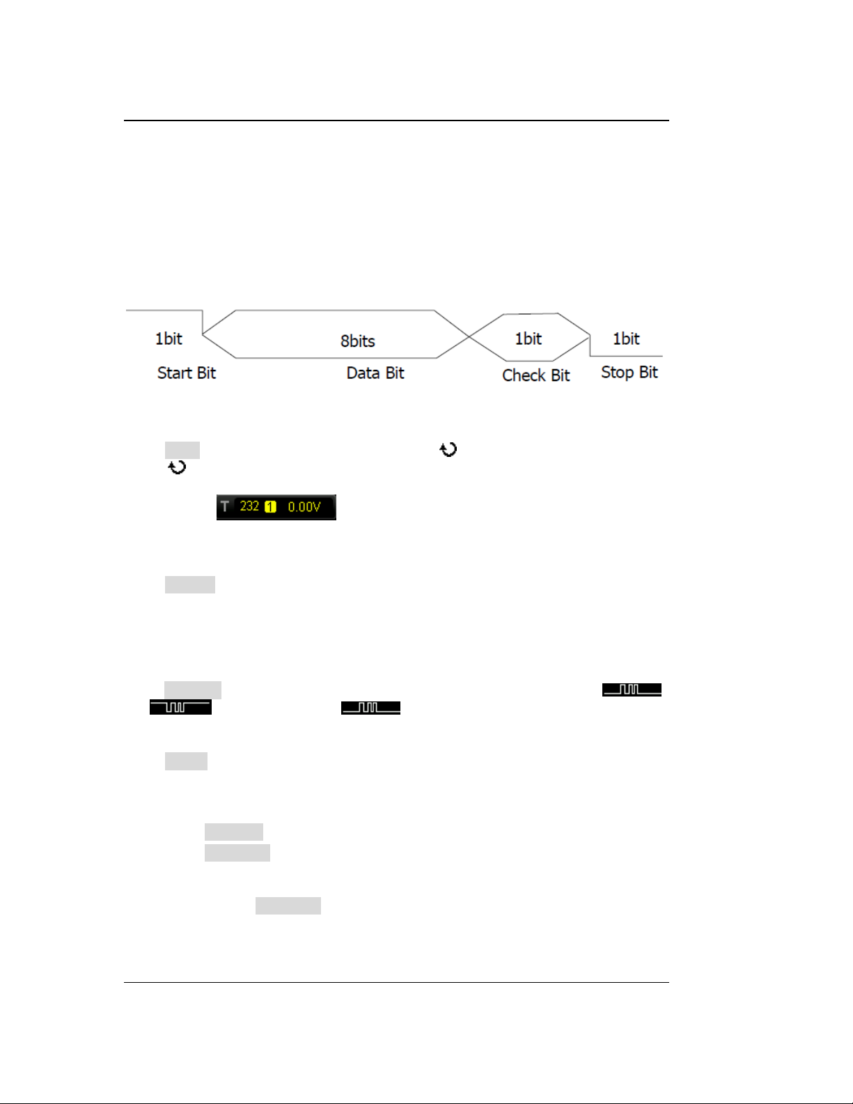
RIGOL Chapter 5 To Trigger the Oscilloscope
RS232 Trigger
RS232 bus is a serial communication mode used in the data transmission between
PCs or between PC and terminal. In RS232 serial protocol, a character is transmitted
as a frame of data which consists of 1 bit start bit, 5~8 bits data bits, 1 bit check bit
and 1~2 bits stop bit(s). Its format is as shown in the figure below. DS1000Z-E series
oscilloscope triggers when the start frame, error frame, check error or the specified
data of the RS232 signal is detected.
Figure 5-13 Schematic Diagram of RS232 Protocol
Trigger Type:
Press Type to open the trigger type list. Rotate to select "RS232" and press
down . At this point, the trigger setting information is displayed at the upper right
corner of the screen.
For example, . The trigger type is RS232 trigger; the current
trigger source is CH1; the trigger level is 0.00 V.
Source Selection:
Press Source to open the signal source list and select CH1 or CH2. For the details,
please refer to the introduction in "Trigger Source". The current trigger source is
displayed at the upper right corner of the screen.
Note: Select channel with signal input as trigger source to obtain stable trigger.
Polarity
Press Polarity to select the polarity of data transmission. It can be set to " "
or " " and the default is .
Trigger Condition:
Press When to select the desired trigger condition.
Start: trigger on the start frame position.
Error: trigger when error frame is detected. After this trigger condition is
selected:
--press Stop Bit to select "1 bit" or "2 bits";
--press EvenOdd to select "None", "Odd" or "Even".
The oscilloscope will determine error frame according to the preset parameters.
ChkError: trigger when check error is detected. When this trigger condition is
selected, press EvenOdd to select "Odd" or "Even". The oscilloscope will
determine check error according to the preset parameters.
Data: trigger on the last bit of the preset data bits. When this trigger condition is
5-32 DS1000Z-E User Guide
Find Quality Products Online at: [email protected]
www.GlobalTestSupply.com
Page 94
Chapter 5 To Trigger the Oscilloscope RIGOL
selected:
--press Data Bits to select "5 bits", "6 bits", "7 bits" or "8 bits";
--press Data and use to set the data value of RS232 trigger. According to
the setting in Data Bits and the ranges can be from 0 to 31, from 0 to 63, from
0 to 127 or from 0 to 255 respectively.
Baud Rate:
Set the baud rate of data transmission (equal to specifying a clock frequency). Press
BaudRate to set the desired baud rate to 2400 bps, 4800 bps, 9600 bps (default),
19200 bps, 38400 bps, 57600 bps, 115200 bps, 230400 bps, 460800 bps, 921600
bps, 1 Mbps and user-defined. When "User" is selected, press Setup to set a more
specific value from 110 bps to 20000000 bps with an adjustment step of 1 bps. For
the setting method, please refer to the introduction in "Parameter Setting
Method".
Trigger Mode:
Press Sweep to open the trigger mode list and select auto, normal or single. For the
details, please refer to "Trigger Mode". The corresponding status light of the
current trigger mode turns on.
Trigger Setting:
Press Setting to set the trigger parameter (noise rejection) under this trigger type.
Trigger Level:
When the trigger source is an analog channel, you can use TRIGGER LEVEL to
modify the level. For the details, please refer to the introduction of "Trigger Level".
DS1000Z-E User Guide 5-33
Find Quality Products Online at: [email protected]
www.GlobalTestSupply.com
Page 95
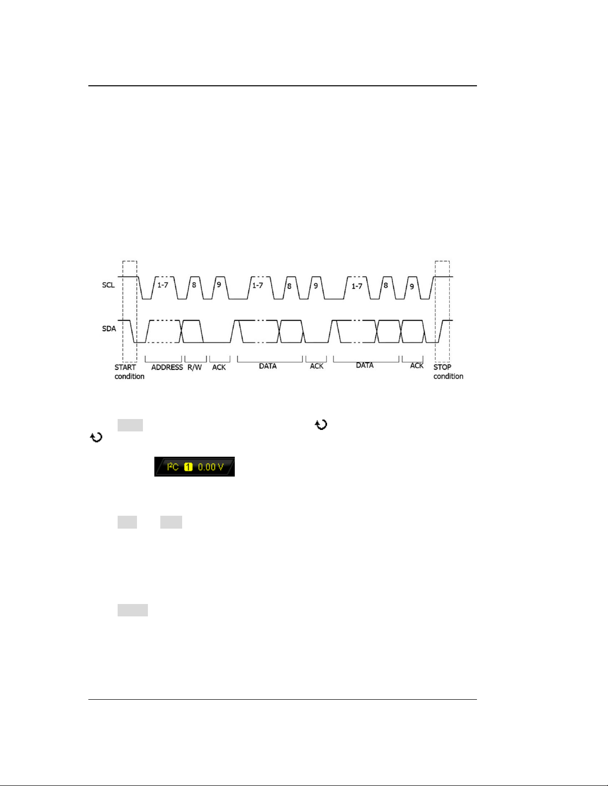
RIGOL Chapter 5 To Trigger the Oscilloscope
I2C Trigger
I2C is a 2-wire serial bus used to connect the microcontroller and its peripheral
device and is a bus standard widely used in the microelectronic communication
control field.
The I2C serial bus consists of SCL and SDA. Its transmission rate is determined by
SCL and its transmission data is determined by SDA, as shown in the figure below.
DS1000Z-E triggers on the start condition, restart, stop, missing acknowledgement,
specific device address or data value. Besides, it can also trigger on the specific
device address and data values at the same time.
Figure 5-14 Schematic Diagram of I2C Protocol
Trigger Type:
Press Type to open the trigger type list. Rotate to select "I2C" and press down
. At this point, the trigger setting information is displayed at the upper right corner
of the screen.
For example, . The trigger type is I2C trigger; the current trigger
source is CH1; the trigger level is 0.00 V.
Source Selection:
Press SCL and SDA to specify the signal sources of SCL and SDA respectively. They
can be set to CH1 or CH2. For the details, please refer to the introduction in "Trigger
Source". The current trigger source is displayed at the upper right corner of the
screen.
Note: Select channel with signal input as trigger source to obtain stable trigger.
Trigger Condition:
Press When to select the desired trigger condition.
Start: trigger when SDA data transitions from high level to low level while SCL is
high level.
Restart: trigger when another start condition occurs before a stop condition.
Stop: trigger when SDA data transitions from low level to high level while SCL is
high level.
5-34 DS1000Z-E User Guide
Find Quality Products Online at: [email protected]
www.GlobalTestSupply.com
Page 96
Chapter 5 To Trigger the Oscilloscope RIGOL
MissedACK: trigger when the SDA data is high level during any
acknowledgement of SCL clock position.
Address: the trigger searches for the specified address value. When this event
occurs, the oscilloscope will trigger on the read/write bit. After this trigger
condition is selected:
--press AddrBits to select "7 bits", "8 bits" or "10 bits";
--press Address to set the address value of I2C trigger. According to the setting
in AddrBits, the range can be from 0 to 0x7F, from 0 to 0xFF or from 0 to
0x3FF;
--press Direction to select "Read", "Write" or "R/W". Note: This setting is not
available when AddrBits is set to "8 bits".
Data: the trigger searches for the specified data value on the data line (SDA).
When this event occurs, the oscilloscope will trigger on the clock line (SCL)
transition edge of the last bit of data. After this trigger condition is selected:
--press Bit X to select the desired data bit and the range is from 0 to (Byte
Length× 8-1);
--press Data to set the data pattern of the current data bit to X, H or L;
--press Bytes to set the length of the data and the range is from 1 to 5;
--press AllBits to set the data pattern of all the data bits to the data pattern
specified in Data.
A&D: the oscilloscope searches for the specified address and data at the same
time and triggers when the specified address and data are found. After this
trigger condition is selected:
--press AddrBits to select "7 bits", "8 bits" or "10 bits";
--press Address and use to set the address value. According to the setting
in AddrBits, the range can be from 0 to 0x7F, from 0 to 0xFF or from 0 to
0x3FF;
--press Bit X to select the desired data bit and the range is from 0 to (Byte
Length× 8-1);
--press Data to set the data pattern of the current data bit to X, H or L;
--press Bytes to set the length of the data and the range is from 1 to 5;
--press AllBits to set the data pattern of all the data bits to the data pattern
specified in Data;
--press Direction to select "Read", "Write" or "R/W".
Note: This setting is not available when AddrBits is set to "8 bits".
Trigger Mode:
Press Sweep to open the trigger mode list and select auto, normal or single. For the
details, please refer to "Trigger Mode". The corresponding status light of the
current trigger mode turns on.
DS1000Z-E User Guide 5-35
Find Quality Products Online at: [email protected]
www.GlobalTestSupply.com
Page 97
RIGOL Chapter 5 To Trigger the Oscilloscope
Trigger Setting:
Press Setting to set the trigger parameter (noise rejection) under this trigger type.
Trigger Level:
When SCL is an analog channel, press SCL and use TRIGGER LEVEL to modify
the trigger level of the SCL channel. When SDA is an analog channel, press SDA and
use TRIGGER LEVEL to modify the trigger level of the SDA channel. For the
details, please refer to the introduction of "Trigger Level".
5-36 DS1000Z-E User Guide
Find Quality Products Online at: [email protected]
www.GlobalTestSupply.com
Page 98
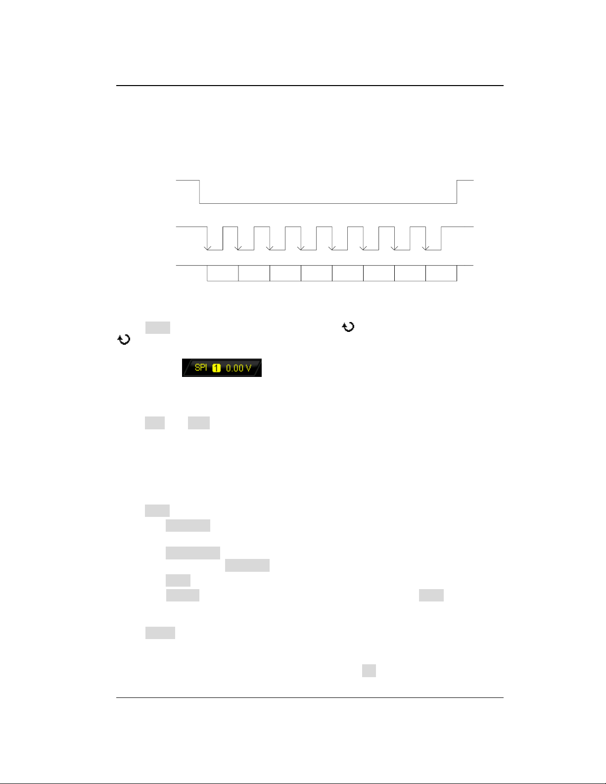
Chapter 5 To Trigger the Oscilloscope RIGOL
SDA
SCL
CS
D7 D6 D5 D4 D3 D2 D1 D0
SPI Trigger
In SPI trigger, after the CS or timeout condition is satisfied, the oscilloscope triggers
when the specified data is found. When using SPI trigger, you need to specify the
SCL clock sources and SDA data sources. Below is the sequential chart of SPI bus.
Figure 5-15 Sequential Chart of SPI Bus
Trigger Type:
Press Type to open the trigger type list. Rotate to select "SPI" and press down
. At this point, the trigger setting information is displayed at the upper right corner
of the screen.
For example, . The trigger type is SPI trigger; the current trigger
source is CH1; the trigger level is 0.00 V.
Source Selection:
Press SCL and SDA to specify the data sources of SCL and SDA respectively. They
can be set to CH1 or CH2. For the details, please refer to the introduction in "Trigger
Source". The current trigger source is displayed at the upper right corner of the
screen.
Note: Select channel with signal input as trigger source to obtain stable trigger.
Data Line Setting:
Press Data to set the data bits and data of SPI trigger.
Press DataBits to set the number of bits of the serial data character string. It
can be set to any integer between 4 and 32.
Press CurrentBit to set the number of the data bit and the range is from 0 to
(value specified in DataBits - 1).
Press Data to set the value of the current bit to H, L or X.
Press AllBits to set all the data bits to the value specified in Data.
Trigger Condition:
Press When to select the desired trigger condition.
CS: if the CS signal is valid, the oscilloscope will trigger when the data (SDA)
satisfying the trigger conditions is found.
― After selecting this condition, you can press CS to select the chip selection
DS1000Z-E User Guide 5-37
Find Quality Products Online at: [email protected]
www.GlobalTestSupply.com
Page 99
RIGOL Chapter 5 To Trigger the Oscilloscope
signal line. The available channels are CH1 or CH2 (only the channels
currently enabled can be selected). For the details, please refer to the
introduction in "Trigger Source". The current trigger source is displayed at
the upper right corner of the screen.
― After selecting this condition, you can press Mode to set the CS mode to
" " (high level is valid) or " " (low level is valid).
Timeout: the clock (SCL) signal need to maintain a certain idle time before the
oscilloscope searches for a trigger. The oscilloscope will trigger on when the data
(SDA) satisfying the trigger conditions is found. After selecting this condition,
you can press Timeout to set the minimum idle time and the range is from 100
ns to 1 s.
Clock Edge:
Press ClockEdge to select the desired clock edge.
: sample the SDA data on the rising edge of the clock.
: sample the SDA data on the falling edge of the clock.
Trigger Mode:
Press Sweep to open the trigger mode list and select auto, normal or single. For the
details, please refer to "Trigger Mode". The corresponding status light of the
current trigger mode turns on.
Trigger Setting:
Press Setting to set the trigger parameter (noise rejection) under this trigger type.
Trigger Level:
When SCL is an analog channel, press SCL and use TRIGGER LEVEL to modify
the trigger level of the SCL channel. When SDA is an analog channel, press SDA and
use TRIGGER LEVEL to modify the trigger level of the SDA channel. For the
details, please refer to the introduction of "Trigger Level".
5-38 DS1000Z-E User Guide
Find Quality Products Online at: [email protected]
www.GlobalTestSupply.com
Page 100
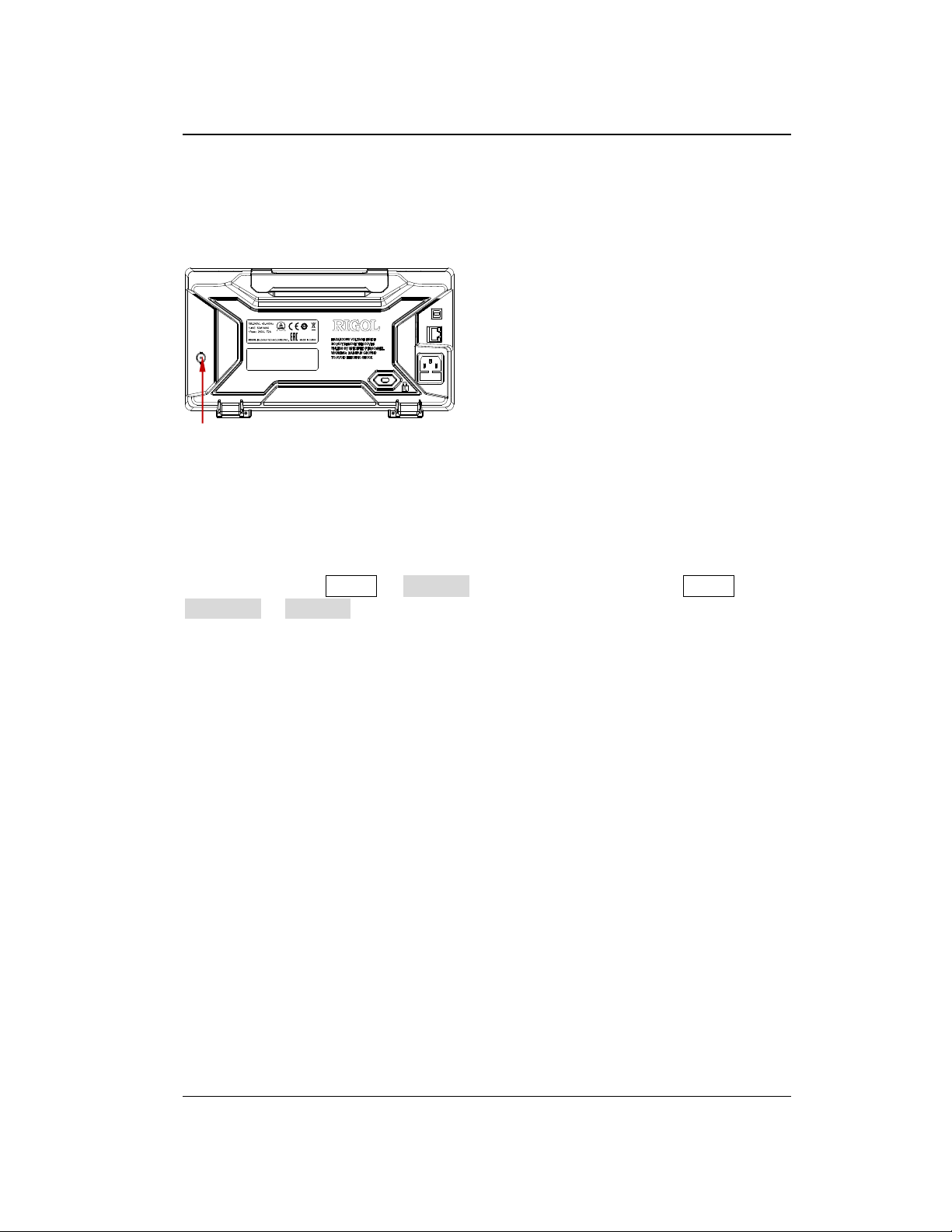
Chapter 5 To Trigger the Oscilloscope RIGOL
Trigger Output Connector
Trigger Output Connector
The trigger output connector ([Trigger Out]) on the rear panel can output trigger
signals determined by the current setting.
A signal which reflects the current oscilloscope capture rate can be output from
[Trigger Out] connector each time a trigger is generated by the oscilloscope. If this
signal is connected to a waveform display device to measure the frequency, the
measurement result is equal to the current capture rate.
Note: If you press Utility Aux Out to select "Pass/Fail" or press Utility
Pass/Fail Aux Out to select "ON", in the pass/fail test, when a failure is detected,
the oscilloscope outputs a negative pulse from the [Trigger Out] connector; when
no failure is detected, the oscilloscope outputs a low level continuously from this
connector.
DS1000Z-E User Guide 5-39
Find Quality Products Online at: [email protected]
www.GlobalTestSupply.com
 Loading...