


User’s Guide RIGOL
Publication number UGA07118-1110
Dec. 2015
DS1000E, DS1000D Series
Digital Oscilloscopes
DS1102E, DS1052E, DS1102D, DS1052D
© 2008 RIGOL Technologies, Inc. All R ights Reserved


RIGOL
I
1. © 2008 RIGOL Technologies, Inc. All Rights Reserved
2. RIGOL products are protected by patent law in and outside of P.R. China.
3. Information in this publication replaces all previously corresponding material.
4. RIGOL Technologies, Inc. reserves the right to modify or c hange part of or all
the specifications and pricing policies at company’s sole decision.
NOTE: RIGOL is registered trademark of RIGOL Technologies, Inc.
© 2008 RIGOL Technologies, Inc.
User’s Guide for DS1000E, DS1000D Series

RIGOL
II
Safety Notices
Review the following saf et y precautio ns caref ully before ope rating the instrument to
avoid any personal injuries or damages to the instrument and any products
connected to it. To avoid potential hazards use the instrument as specif ied by this
user’s guide only.
The instrument should be serviced by qualified personnel only.
Avoid Fire or Personal Injury.
Use Proper Power Cord. Use the power cord designed for the instrument and
authorized in your country only.
Connect and Disconnect Accessories. Do not connect or disconnect probes or
test leads while they are connected to a voltage source.
Ground The Instrument. The oscilloscope is grounded through the grounding
conductor of the power cord. To avoid electric shock the instrument grounding
conductor(s) must be grounded properly . Bef ore making connections t o the in put or
output terminals of the instrument.
Connect The Probe. The probes’ grou nd terminals are at the same v oltage lev el of
the instrument ground. Do not connect the ground terminals to a high voltage.
Observe All Terminal Ratings. To avoid fire or shock hazard, observe all ratings
and marks on the instru ment . F ollow the user’ s guide for further r atin gs inf ormatio n
before making connections to the instrument.
Do Not Operate Without C ove rs. Do n o t op e ra te the instrument with covers or
panels removed.
Use Proper Fuse. Use the f use of the type, voltage and current ratings as specified
for the instrument.
Avoid Circuit or Wire Exposure. Do not touch exposed connections and
components when power is on.
Do Not Operate With Suspected Failures. If suspected damage occurs with the
instrument, have it inspected by qualified service personnel before further
operations.
Provide Proper Ventilation. Refer to the installation instructions for proper
ventilation of the instrument.
© 2008 RIGOL Technologies, Inc.
User’s Guide for DS1000E, DS1000D Series

III
RIGOL
Do not operate in wet/damp conditions
Do not operate in an explosive atmosphere
Keep product surfaces clean and dry
The disturbance test of all the models meet the limit values of A in the
standard of EN 61326: 1997+A1+A2+A3, but can’t meet the limit values
of B.
Measurement Category
The DS1000E, DS1000D series Digital Oscilloscope is intended to be used for
measurements in Measurement Category I.
Measurement Category Definitions
Measurement Category I is for measurements performed on circuits not directly
connected to MAINS. Examples are measurements on circuits not derived from
MAINS, and specially protected (inte rnal ) MAI NS de riv ed circuits. In the latter case,
transient stresses are variable; for that reason, the transient withstand capabil ity of
the equipment is made known to the user.
WARNING
IEC Measurement Category I, The input terminals may be connected to circuit
terminal in IEC Category I installations for voltages up to 300 VAC. To avoid the
danger of electric shock, do not connect the inputs to circuit’s voltages above 300
VAC. Transient overvoltage is also present on circuits that are isolated from mains.
The DS1000E, DS1000D series Digital Oscilloscopes is designed to safely withstand
occasional transient overvoltage up to 1000Vpk. Do not use this equipment to
measure circuits where transient overvoltage could exceed this level.
© 2008 RIGOL Technologies, Inc.
User’s Guide for DS1000E, DS1000D Series

RIGOL
IV
!
Hazardous
Safety
Protective
Test
Grounding
!
!
Safety Terms and Symbols
Terms in This Guide: These terms may appear in this guide:
WARNING: Warning statement s identify conditions or practices that could
result in injury or loss of life.
CAUTION: Caution statements identify conditions or practices that could
result in damage to this product or other property.
Terms on the Product: These terms may appear on the product:
DANGER: indicates an injury hazard may be immediately accessible.
WARNING: indicates a potential injury hazard may be immediately accessible.
CAUTION: indicates that a potential damage to the instrument or other property
might occur.
Symbols on the Product: These symbols may appear on the product:
Voltage
Warning
Earth Terminal
Terminal
of Chassis
Grounding
Terminal
© 2008 RIGOL Technologies, Inc.
User’s Guide for DS1000E, DS1000D Series

V
RIGOL
General-Purpose Oscillos cop e s
This book covers the following four types of DS1000E, DS1000D Series Digital
Oscilloscopes:
DS1102E, DS1052E
DS1102D, DS1052D (With Logic Analyzer)
DS1000E, DS1000D series are kinds of economical digital oscilloscope with
high-performance. DS1000E series are designed with dual channels and 1 external
trigger channel. DS1000D series are design ed with dual channels and 1 external
trigger channel as well as 16 channels logic analyzer.
The front panel of DS1000E, DS100 0D series digital oscilloscopes are clear, direct
viewing and easy to use, which consistent with the traditional instrument use fully.
To speed up the adjustment and measurement, please press AUTO button to get
suitable wav eform display and set tings. Besides, 1GSa/s maximum real-time sample
rate, 25GSa/s maximum equivalent sample rate and the powerful trigger and
analyzer functions enable users view or capture the wav e form more detailed and
faster.
Main Features
Dual analog channels, 1GSa/s maximum real-time sample rate and 25GSa/s
maximum equivalent sample rate, Bandwidth of per channel:
100MHz (DS1102E, DS1102D)
50MHz (DS1052E, DS1052D)
Optional 16 digital channels (DS1000D series), each channel can be tu rn ed on
or off independently, or in a 8 bit group
5.6 inch and 64 k TFT LCD
Abundant trigger types: Edge, Pulse Width, Video , Slope , Alternate, Pattern and
Duration Trigger (Only for DS1000D series)
Unique adjustable trigger sensitivity enables to meet different demands
Enable t o measur e 22 types of wave p arameter s and track measurements via
cursor automatically
Unique waveform record a nd replay function
Fine delayed scan function
Built-in FFT function, hold practical digital filters
© 2008 RIGOL Technologies, Inc.
User’s Guide for DS1000E, DS1000D Series

RIGOL
VI
Provide 4 types of digital filters: LPF, HPF, BPF, BRF
Pass/Fail detection function enables to output testing results
Math operations available to multiple waves
Powerful PC applic ation soft ware UltraScope
Standard configuration interface: USB Device, USB Host ,RS-232 and support
USB storage device storage and PictBridge print standards
The new function “Special Mode” can meet the needs of industrial production
Support f or remote command control
Built-in help menu enables information getting more convenient
Multiple Language User Interface, support Chinese & English input
Can store files into USB storage device or the internal memory
Waveform intensity can be adjusted
To display a signal automatically by AUTO
Pop-up menu makes it easy to read and use
© 2008 RIGOL Technologies, Inc.
User’s Guide for DS1000E, DS1000D Series

RIGOL
VII
Content
Safety Notices ......................................................................................... II
General-Purpose Oscilloscopes .................................................................. V
Chapter 1 Quick Start ........................................................................ 1-1
To Inspect the Instrument ..................................................................... 1-2
The Panels and User Interface ................................................................ 1-3
Appearance and Dimensions ................................................................... 1-7
To Perform a Functional Check ............................................................... 1-8
To Compensate Probes ........................................................................ 1-10
Digital Leads (Only for DS1000D Series) ................................................ 1-11
To Display a Signal Automatically .......................................................... 1-13
To Understand the Vertical System ....................................................... 1-14
To Understand the Horizontal System .................................................... 1-16
To Understand the Trigger System ........................................................ 1-18
Chapter 2 Operating Your Oscilloscope ............................................. 2-1
To Set up the Vertical System ................................................................. 2-2
To Set up the Horizontal System ........................................................... 2-27
To Set up the Trigger System ............................................................... 2-34
To Set up the Sampling System ............................................................ 2-53
To Set up the Display System ............................................................... 2-57
To Store and Recall ............................................................................. 2-59
To Set up the Utility System ................................................................. 2-67
To Measure Automatically .................................................................... 2-88
To Measure with Cursors ...................................................................... 2-95
To Use Run Contr ol Butto ns ............................................................... 2-102
Chapter 3 Application & Examples ..................................................... 3-1
Example 1: Taking Simple Measurements ................................................ 3-1
Example 2: View a Signal Delay Caused by a Circuit.................................. 3-2
Example 3: Capture a Single-Shot Signal ................................................. 3-3
Example 4: To Reduce the Random Noise on a Signal ............................... 3-4
Example 5: Making Cursor Measurements ................................................ 3-6
Example 6: The application of the X-Y operation ...................................... 3-8
Example 7: Triggering on a Video Signal ................................................ 3-10
Example 8: FFT Cursor measurement .................................................... 3-12
© 2008 RIGOL Technologies, Inc.
User’s Guide for DS1000E, DS1000D Series

RIGOL
VIII
Example 9: Pass/Fail Test .................................................................... 3-13
Example 10: Triggering on a Digital Signal ............................................ 3-14
Chapter 4 Troubleshooting ................................................................ 4-1
Chapter 5 Specifications .................................................................... 5-1
Specifications ....................................................................................... 5-2
General Specifications ........................................................................... 5-6
Chapter 6 Appendix ........................................................................... 6-1
Appendix A: Acce s s ories ........................................................................ 6-1
Appendix B: Warranty ........................................................................... 6-2
Appendix C: Care and Cleaning .............................................................. 6-3
Appendix D: Contact Us ......................................................................... 6-4
Index ...................................................................................................... 1
© 2008 RIGOL Technologies, Inc.
User’s Guide for DS1000E, DS1000D Series

1-1
Chapter 1 Quick Start
This chapter covers the following topics:
To Inspect the Instrument
The Panels and User Interface
Appearanc e and Dimen s io ns
To Perform a Functional Check
To Compensate Probes
Digital Leads (Only for DS1000D Series)
To Display a Signal Automatically
To Understand the Vertical System
To Understand the Horizontal System
RIGOL
To Understa nd the Trigger Syste m
© 2008 RIGOL Technologies, Inc.
User’s Guide for DS1000E, DS1000D Series

RIGOL
1-2
To Inspect the Instrum e nt
When you get a new DS1000E, DS1000D series oscilloscope, please inspect the
instrument according to the following steps:
1. Inspect the shipping container for damage.
Keep a damaged shipping container or cushioning material until the contents of
the shipment have been checked for completeness and the instrument has been
checked mechanically and electrically.
2. Inspect the instrument.
In case t here is any mechanical damage or defect, or the instrument does not
operate properly or fails performance tests, please notify the RIGOL Sales
Representative.
If the shipping container is damaged, or the cushioning materials show signs of
stress, please notify the carrier as well as the RIGOL sales off ice. Keep the
shipping materials for the carrier’s inspection. RIGOL offices will arrange for
repair or replacement at RIGOL’s option without waiting for claim settlement.
3. Check the accessories.
Accessories supplied with the instrument are listed in "Appendix A: Accessories"
in this guide.
If the contents are incomplete or damaged, please notify your RIGOL Sales
Representative.
© 2008 RIGOL Technologies, Inc.
User’s Guide for DS1000E, DS1000D Series

RIGOL
1-3
The Panels and User Interface
The f irst thing to do with a new oscilloscope is to know its front panel. This chapter
helps to be familiar with the layout of the knobs and buttons and how to use them.
Read the chapter carefully before further operations.
1. Front Panel
Figure 1- 1, Front P anel; the knobs a re use d most often a nd are si milar t o the kno bs
on other oscilloscopes. The buttons allow you to use some of the functions directly
but also bring up soft but t on men us on the screen, which enable the access to many
measurement features associated with advanced functions, mathematics, and
reference or to run control fea t u res.
The front panel of DS1000E:
The front panel of DS1000D:
Figure 1- 1
Front Panel Figure of DS1000E, DS1000D Series Oscilloscope
© 2008 RIGOL Technologies, Inc.
User’s Guide for DS1000E, DS1000D Series

RIGOL
1-4
Multi-function Common Menu Run Control
Knob Buttons Buttons
Trigger Control
Horizontal
Control
Vertical Control
USB Host Logic Analyzer Port
Signal Input EXT Trigger Probe
Channel Input Compensation
Figure 1- 2
Front Panel Instruction
2. Rear Panel
Figure 1- 3
Rear Panel Figure of DS1000E, DS1000D Series Oscilloscope
© 2008 RIGOL Technologies, Inc.
User’s Guide for DS1000E, DS1000D Series

RIGOL
1-5
Figure 1- 4
Rear Panel Instruction
Rear Panel of DS1000E, DS10000D series contains the following parts:
① Pass/Fail output port: The Pass /Fail tes ting results can be output by the port.
② RS232 port: To connect the oscilloscopes and external equipment as serial
port.
③ USB Device port: It is used to transfer data when external USB equipment
connects to the oscilloscope regarded as “Device equipment”. For example: to
use this port when connect PictBridge printer to the instrument by USB.
Notation definitions in this User’s Guide:
Throughout this manual, notation symbols of buttons and knobs are the same to
those on front-panel.
A box around the name of the button denotes MENU function buttons on
front-panel, such as Measure.
denotes the multi-function knob .
denotes the two POSITION knobs.
denotes the two SCALE knobs.
denotes the LEVEL knob.
The name with a drop shadow denotes the menu operating button, such as
Storage denoting the "Storage" menu item under Measure.
© 2008 RIGOL Technologies, Inc.
User’s Guide for DS1000E, DS1000D Series

RIGOL
1-6
Waveform
Menu
Location of
in memory
Trigger point in
waveform window
Trigger point
in memory
Turn off
Digital
channels
Horizontal
Trigger
Channel coupling
Turn on
3. User Interface
Running status
Channel 1
Channel 2
Running status
waveform window
Figure 1- 5
Display screen (Analog channels only)
digital channels
digital channels
display window
© 2008 RIGOL Technologies, Inc.
Channel 1
and vertical div
time base div
Figure 1- 6
User Interface (Analog and Digital channels)
User’s Guide for DS1000E, DS1000D Series
offset

1-7
Appearance and Dimensions
Figure 1- 7 Front View
RIGOL
Figure 1- 8 Side View
© 2008 RIGOL Technologies, Inc.
User’s Guide for DS1000E, DS1000D Series

RIGOL
1-8
Power button
!
To Perform a Functional Check
Perform this quick functional check to verify that the instrument is operating
correctly.
1. Turn on the instrument.
Use the power cord designed for the oscilloscope only.
The power requirements are 100 to 240 VAC
T urn on the instruments, a nd wait until the display shows the waveform window.
Press the Storage button, select Storage in the menu. Rotate the multiple
function knob to select Factory and press the knob down. Then, press Load .
, 45Hz to 440Hz.
RMS
Storage button
Figure 1- 9
Turn on and Check the instrument
WARNING:
To avoid electric shock, be sure the oscilloscope is properly grounded.
2. Input a signal to a channel of the oscilloscope
DS1000E series: 2 channels input + 1 external trigger channel input
DS1000D series: 2 channels input + 1 external trigger channel input +16 chann els
digital input
Do the following steps:
① Set the switch on the probe to 10X and connec t the probe to Channel1 on the
oscilloscope:
© 2008 RIGOL Technologies, Inc.
User’s Guide for DS1000E, DS1000D Series

1-9
Align the slot in the probe connector with the button on the CH1 BNC.
Push to connect, and twist to the right to lock the probe.
Attach the probe tip and ground lead to the PROBE COMP connector.
Probe compensator
Figure 1- 10
Attach the probe
② Set the probe attenuation to 10X. To do this, push CH1→Probe→10X.
RIGOL
Probe scale
Figure 1- 11 Figure 1- 12
Set attenuation on the probe Set attenuation in the menu
③ Push the AUTO button. Within a few seconds, a square wave will display.
④ Push the CH1 button a gain to turn off Channel1.
Push the CH2 butt on to turn on c hannel2, r epeat step s 2 and 3.
NOTE: The signal output from Prob e compensator should only be used for probe
compensation, not for calibration.
© 2008 RIGOL Technologies, Inc.
User’s Guide for DS1000E, DS1000D Series

RIGOL
1-10
!
To Compensate Probes
Perform this adjustment to match the characteristics of the probe and the channel
input. This should be performed whenever attaching a probe to any input channel for
the f i r st time.
1. From CH1 menu, set the Probe attenuation to 10X (press CH1→Probe→10X).
Set the switch to 10X on the probe and connect it to CH1 of the oscilloscope.
When using the probe hook-tip, inserting the tip onto the probe firmly to ensure
a proper connection.
Attach the probe tip to the Probe compensa tor connector and the reference lead
to the ground pin, Select CH1, and t hen press AUTO.
2. Ch eck the shape of the displayed waveform.
Over compensated Correctly Compensated Under Compensated
Figure 1-9
Figure 1- 13
Probe Compensation
3. If necessary , use a non-metallic tool to a djust the t rimmer ca pacitor on the pro be
for the flattest square wave possible as displayed on the oscilloscope.
4. Repeat as necessary.
WARNING: To avoid electric shock while using the probe, be sure the
perfection of the insulated cable, and do not touch the metallic portions of
the probe head while it is connected with a voltage source.
© 2008 RIGOL Technologies, Inc.
User’s Guide for DS1000E, DS1000D Series

RIGOL
1-11
!
Digital Leads (Only for DS1000D Series)
Digital leads are provided only for DS10 0 0D series which have Logic Analyzer.
1. Switch off power supply of the device under test if necessary to avoid short
circuit. Since no voltage is applied to the leads at this step, you may keep the
oscilloscope on.
2. Connect one end of the flat cable FC1868 to the Logic Analyzer Input; connect
the other end to Logic Head LH1116. An identifier is located on each end of the
flat cable; it can only be connected in one way. It is unnecessary to switch off
power supply of your oscilloscope when connecting the cable.
Figure 1- 14
Connect the digital leads
CAUTION: Use only FC1868, LH1116, TC1100 and LC1150 made by
RIGOL for specified DS1000D series.
3. Connect a test clip to one lead wire; make sure it’s connection good.
Test clip
Figure 1- 15
Input Interface of Digital Channel
© 2008 RIGOL Technologies, Inc.
User’s Guide for DS1000E, DS1000D Series

RIGOL
1-12
4. Test your device with the clip.
Figure 1- 16
Digital Channel Measurement
5. Remember to connect Ground Channel to the DUT’s ground terminal.
GND
Figure 1- 17
Connecting to the Ground
© 2008 RIGOL Technologies, Inc.
User’s Guide for DS1000E, DS1000D Series

RIGOL
1-13
To Display a Sig nal Automatically
The oscilloscope has an automated feature to display the input signal best-fit. The
input signal should be 50Hz or higher and a duty cycle is greater than 1%.
Use Auto Setting:
1. Connect a signal to the oscilloscope as described above.
2. Press AUTO.
The oscilloscope will automatically set up VERTICAL, HORIZONTAL and TRIGGER
controls to display the input signal. Adjust the controls manually to get the best
results if necessary.
© 2008 RIGOL Technologies, Inc.
User’s Guide for DS1000E, DS1000D Series

RIGOL
1-14
To Understand the Vertical System
Figure 1- 18 shows the VERTICAL controls, CH1, CH2, MATH, REF and OFF buttons
and vertical , knobs. Following the exercise of the buttons,
knobs, and the status bar to be familiar with the vertical parameters settings.
Figure 1- 18
The vertical system
1. Moves the signal vertically on the display with the
knob.
When turning the
knob, a voltage value is displayed for a short time
indicating its value with respect to the ground reference located at the center of the
screen. Also notice that the ground symbol on the left side of the display moves in
conjunction with the
knob.
Measurement hints
If the channel is DC coupled, measuring the DC component of the signal by
simply noting its distance from the ground.
If the channel is AC coupled, the DC comp onent of th e signal is blocke d, allow
you to use greater sensitivity to display the AC component of the signal.
© 2008 RIGOL Technologies, Inc.
User’s Guide for DS1000E, DS1000D Series

1-15
knob to change the vertical display position of
, this is especially helpf ul when t he tr ace positio n is
pressing the vertical
Vertical offset back to 0 shortcut key
RIGOL
Turn the
channel and press the knob to set the vertical display position
back to 0 as a shortcut key
far out of the sc reen and want it to get ba ck to the screen center immediately.
2. Change the vertical setup and notice that each change affects the
status bar differently.
View the status bar which is on the bottom of the screen to understand the
vertical scale.
Change the ve rtical scale by turning the
knob and notice the change
in the status bar.
Press CH1 , CH2 , MATH , REF , LA (only for DS1000D series) to display
the menu, sign, waveform of corresponding channel. Press OFF button to turn
off the channel.
Coarse/Fine Shortcut key
The Coarse/Fine vertical control can be set by simply
knob.
© 2008 RIGOL Technologies, Inc.
User’s Guide for DS1000E, DS1000D Series

RIGOL
1-16
is another way to enter or exit Delayed Scan mode and it is equal to the
To Understand the Horizontal System
Figure 1-19 shows the HORIZONTAL controls: MENU button, and
knobs of horizontal system. Following the exercise to familiarize with the
buttons, knobs, and status bar.
Figure 1- 19
The horizontal system
1. Turn the
knob and notice the change in the status bar.
The horizontal
knob changes the sweep speed in a 1-2-5 step
sequence, and displays the value in the status bar. The time base rang e s o f th e
oscilloscope is from 2ns/div* to 50s/div.
Delayed Scan Shortcut key
To press the
knob in the horizontal contr ol a rea on the f ront -panel
following menu operations, MENU→Delayed→ON.
* NOTE: The speed of horizontal scan varies by different models.
© 2008 RIGOL Technologies, Inc.
User’s Guide for DS1000E, DS1000D Series

RIGOL
1-17
Horizontal offset back to 0 shortcut key
, this is especially hel pful whe n the trigger point i s far out of the screen and
Horizontal position control
to move the trigger
2. The horizontal
knob moves displayed signal horizontally
on waveform window
Turn the horizontal
knob to adjust trigger offset. The waveform
will move horizontally at the same time.
Press the knob to s et the horizontal offset to 0 as a shortcut
key
want it to get back to the screen center immediately.
3. Press the MENU button to display the TIME menu.
To enter or exit the Delayed Scan mode, set the display to Y -T, X-Y or ROLL mode,
or reset the trigger offset.
Trig-Offset: The position of the practical trigger point relative to center of
the memory. Adjust the horizontal
knob
point horizontally.
© 2008 RIGOL Technologies, Inc.
User’s Guide for DS1000E, DS1000D Series

RIGOL
1-18
To Understand the Tr igger System
Figur e 1-20 shows the trigger control: MENU, 50%, FORCE and a trigger
level knob. Following the exercise to familiarize with the buttons, trigger level knob
and status bar.
Figure 1-20
The trigger control window
1. Turn the trigger Level knob and notice the changes on the display.
As you turn the
knob or pressing the 50% button, two things will happen
on the display for a short time.
First, the trigger level value is displayed at the bottom-left of the screen.
Second, a line is displayed showing the location of the trigger level (as long as
AC coupling or low frequency reject are not selected).
Trigger Level to 0 Shortcut key
Turn the knob to change trigger level value and press the
knob to set tri gger level back to 0 as a sho rtcut key.
© 2008 RIGOL Technologies, Inc.
User’s Guide for DS1000E, DS1000D Series

RIGOL
1-19
A time interval before the oscilloscope response to next trigger
2. Change the trigger setup and notice these changes in the statu s ba r.
Press MENU button in the Trigger control. A soft button me nu appears on the display
showing the trigger setting choices as shown in Figure 1 -21.
Figure 1- 21
· Press the trigger Mode button and choose Edge.
· Press the trigger Source button to select CH1.
· Press the trigger Slope button to choos e .
· Press the trigger Sweep button to select Auto.
· Press the trigger Set Up button to enter secondary menu.
NOTE: The trigger type, slope and source cha nge in conjun ction with the status bar
on the top-right of the screen.
3. Press 50%
The 50% button sets the trigger level to the center of the signal.
4. Press FORCE
Starting an acquisition regardless of an adequate trigger signal, usually used in
“Normal” or “Single” trigger mode. This button has no effect if the acquisition is
already stopped.
Key point:
Holdoff:
signal. During this holdoff period, the trigger system becomes “blind” to trigger
signals. This function helps to view complex signals such as an AM waveform.
Press Holdoff button to activate (
© 2008 RIGOL Technologies, Inc.
User’s Guide for DS1000E, DS1000D Series
) knob, then turn it to adjust Holdoff time.


RIGOL
2-1
Chapter 2 Operating Your Oscilloscope
By now, a user should understand the VERTICAL, HORIZONTAL and TRIGGER
control systems and knows how to determine the system setup by status bar of a
DS1000E, DS1000D series digital oscilloscope.
This chapter will go through all groups of front-panel buttons, knobs and menus;
and further the knowledge of the operation by hints in this guide.
It is recommended to perform all of the following exercises to get the most of the
powerful measurement capabilities of the oscilloscope.
This chapter contains the following topics:
To Set up the Vertical System
( CH1, CH2, MATH, REF, LA (for DS1000D series) OFF, Vertical
Vertical )
To Set up the Horizontal System
( MENU, Horizontal
To Set up the Trigger System ( , MENU, 50%, FORCE)
To Set up the Sampling System ( Acquire)
To Set up the Display System ( Display)
To Store and Recall ( Storage)
To Set up the Utility System ( Utility)
To Measure Automatically ( Measure)
To Measure with Cursors ( Cursor)
To Use Run Control Buttons ( AUTO, RUN/STOP)
Please refer to this chapter more carefully to get more information of the
measurement and operation methods of DS1000E and DS1000D.
, Horizontal )
,
© 2008 RIGOL Technologies, Inc.
User’s Guide for DS1000E, DS1000D Series

RIGOL
2-2
cks the DC component of the
Limits the channel bandwidth to
attenuation factor to make the
Go to the next menu page (The
more explanation)
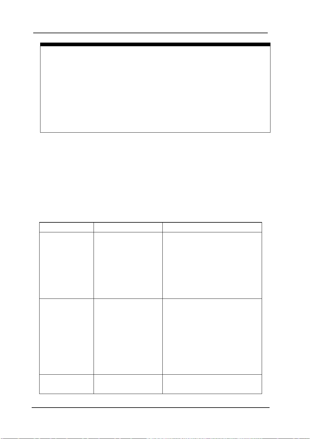
To Set up the Vertical System
Settings of the Channels
This series oscilloscopes offer dual channels. Each channel has an operation menu
and it will pop up after pressing CH1 or CH2 button. The settings of all items in the
menu is shown in the table below.
Figure 2- 1 Table 2- 1 The Channel menu (Page 1/2)
Menu Settings Comments
Coupling
BW Limit
Probe
Digital filter
AC
DC
GND
ON
OFF
1X
5X
10X
50X
100X
500X
1000X
Blo
input Signal
Passes both AC and DC
components of the input signal
Disconnects the input signal
20MHz to reduce display noise.
Get full bandwidth.
Set this to ma tc h yo ur probe
vertical scale readout corre ct
Setup digital filter (See table 2-4)
© 2008 RIGOL Technologies, Inc.
1/2
User’s Guide for DS1000E, DS1000D Series
followings are the same, no

2-3
(The followings are the same, no
Selects the resolution of the
original display of the
AC coupling
AC coupling
Figure 2- 2 Table 2- 2 The Channel Menu (Page 2/2)
Menu Settings Comments
RIGOL
2/2
Back to the previous menu page
more explanation)
knob
Volts/Div
Invert
Coarse
Fine
ON
OFF
Def in es a 1-2-5 sequence.
To c hange the resolution to small
steps between the coarse settings.
Turn on the invert function.
Restore
waveform.
1. Channel coupling
To use Channel 1 as an example, input a sine wave signal with DC shift.
Press CH1→Coupling→AC to set “AC” coupling. It will pass AC component and
blocks the DC component of the in put signal. The waveform is displayed as Figure 23:
status symbol
© 2008 RIGOL Technologies, Inc.
setup
Figure 2- 3
AC coupling setting
User’s Guide for DS1000E, DS1000D Series

RIGOL
2-4
GND coupling
GND coupling
status symbo l
DC coupling
DC coupling
Press CH1→Coupling→DC, to set “DC” coupling. It will pass both AC and DC
components of the input signal. The waveform is displayed as Figure 2- 4:
setup
status symbo l
Figure 2- 4
DC coupling setting
Press CH1→Coupling→GND, to set “GND” coupling, it blocks the input signal.
The screen displays as Figure 2-5:
setup
Figure 2- 5
GND coupling setting
© 2008 RIGOL Technologies, Inc.
User’s Guide for DS1000E, DS1000D Series

RIGOL
2-5
Turn off the BW
limit
Mark of
2. Set up the channel bandwidth limit
To take Channel1 as an example, input a signal containing high frequency
component. Press CH1→BW L im it →OFF, to set up bandwidth limit to “OFF” status.
The oscilloscope is set to full bandwidth and passing the high frequen cy com ponent
in the signal. The waveform is displayed a s
Figure 2- 6:
Figure 2- 6
Turn off the BW limit
Press CH1→BW Limit→ON, to set up bandwidth limit to “ON” status. It will reject
the frequency component higher than 20MHz.
20M BW limit
BW limit
Figure 2- 7
Turn on the BW limit
© 2008 RIGOL Technologies, Inc.
User’s Guide for DS1000E, DS1000D Series

RIGOL
2-6
Probe
attenuation
3. Probe Attenuation Setting
The oscilloscope allows selecting the attenuation factor for the probe. The
attenuation factor changes the vertical scaling of the oscilloscope so that the
measurement results reflect the actual voltage levels at the probe tip.
To change (or check) the probe attenuation setting, press the CH1 or CH2 button
(according to which channel in using). Press the Probe so ft button to match the
attenuation factor of the probe. This setting remains in effect until changed again.
Figure 2-8 shows an example for using a 1000:1 probe and its attenuation factor.
Vertical volt/div.
Figure 2- 8
Use the 1000:1 attenuation
Table 2- 3 Probe setting
Probe attenuation factors Corresponding settings
1:1 1X
5:1 5X
10:1 10X
50:1 50X
100:1 100X
500:1 500X
1000:1 1000X
© 2008 RIGOL Technologies, Inc.
User’s Guide for DS1000E, DS1000D Series

RIGOL
2-7
4. Digital Filter settings
DS1000E, DS1000D series offer 4 types of digital filters (Low Pass Filter, High Pass
Filter, Band Pass Filter and Band Reject Filter). In order to achieve a good filter effect,
you can filter the special waveform frequency by setting up the range of filter
bandwidth. Press CH1→Digital filter, display the digital f ilter menu. Turn ( ) knob
to set high and low limit of frequency.
Turn off digital filter
Figure 2- 9
The waveform when turning off digital filter
Turn on digital filter
Mark of digital filter
Figure 2- 10
The waveform when turning on digital filter
© 2008 RIGOL Technologies, Inc.
User’s Guide for DS1000E, DS1000D Series

RIGOL
2-8
Back to higher level menu (The
followings are the same)
Figure 2- 11 Table 2- 4 The Filter menu
Menu Settings Comments
Digital Filter
ON
OFF
Turn on the digital f ilter
Turn off the digital filter
Setup as LPF (Low Pass Filter)
Setup as HPF (High Pass Filter)
Filter Type
Setup as BPF (Band Pass Filter)
Setup as BRF (Band Reject Filter)
Upper limit
Lower limit
<frequency>
<frequency>
Turn (
Turn (
) knob to set high limit
) knob to set low limit
5. Volts/Div settings
The Volts/Div control has Coarse or Fine configuration. The Vertical Sensitivity is
2mV/div - 10V/div. Coarse: It is the default setting of Volts/Div in a 1-2-5-step
sequence from 2mV/div, 5mV/div, 10mV/div, 20mV/div……10V/div. Fine: This
setting changes the vertical scale to small steps between the coarse settings. It will
be helpful to adjust the waveform in smooth steps.
Fine adjustment data
© 2008 RIGOL Technologies, Inc.
Fine adjustment
Figure 2- 12 Fine configurations
User’s Guide for DS1000E, DS1000D Series

RIGOL
2-9
Coarse/Fine Shortcut key:
To change Coarse/Fine setting, not only by menu but also by pressing vertical
knob
6. To invert a waveform
Invert t urns the displayed waveform 180 degrees, as respect to the ground level.
Figure 2- 13 and Figur e 2- 14 show the changes after inversion.
Invert OFF
Figure 2- 13 The waveform before inversion
Invert ON
Figure 2- 14 The waveform aft er invers ion
© 2008 RIGOL Technologies, Inc.
User’s Guide for DS1000E, DS1000D Series

RIGOL
2-10
A+B
FFT
Add source A and source B
Fast Fourier Transform
CH1
CH2
CH1
CH2
ON
OFF
Invert the MATH waveform.
Restore to original waveform display.
Math Functions
The mathematic functions include “Add”, “Subtract”, “Multiply” and “FFT” for
Channel 1 and Channel 2. The mathematic result can be measured by grid and
cursor. Press MATH button, the system enter the MATH interface as follows:
MATH scale
The Math function
Figure 2- 16 Table 2- 5 The Math menu
Figure 2- 15
© 2008 RIGOL Technologies, Inc.
Menu Settings Comments
Operation
Source A
Source B
A-B
A×B
Subtract source B from source A
Multiply source B by source A
Define CH1 or CH2 as source A
Define CH1 or CH2 as source B
Invert
User’s Guide for DS1000E, DS1000D Series

RIGOL
2-11
1. Using the FFT
FFT (Fast Fourier Transform) transforms time domain signals to frequency domain
signals. The horizontal axis shows the frequency and the vertical axis shows the
amplitude dBVrms or Vrms. FFT function can not only to help you find crossfire
problem and analog waveform distortion caused by n onlinear a mplifier, but also can
adjust the analog filter.
FFT waveforms are useful in the following applications:
Measuring harmonic content and distortion in systems
Characterizing noise in DC power supplies
Analyzing vibration
Press MATH→Operate→FFT, to display FFT menu.
Figure 2- 17 Table 2- 6 The FFT menu
Menu
Operate
Source
Window
Display
Scale
Settings Comments
A+B
A-B
A x B
FFT
CH1
CH2
Add source A to source B
Subtract source B from sourc e A
Multiply source B by source A
Fast Fourier Transform
Define CH1 or CH2 as FFT source
Rectangle
Hanning
Select window for FFT
Hamming
Blackman
Split
Full screen
Vrms
dBVrms
Display FFT waveform on half screen
Display FFT waveform on full screen
Set “Vrms ” as vertical unit
Set “dBVrms ” as vertical unit
© 2008 RIGOL Technologies, Inc.
User’s Guide for DS1000E, DS1000D Series
RIGOL
2-12
Hamming has slightly
Signals that have a DC component or offset can cause incorrect FFT waveform
T o display FFT wa veforms wi th a large d ynamic rang e, use the d BVrms scale. The
Key points for FFT
component magnitude values. To minimize the DC component, choose AC
Coupling on the sourc e signal.
To reduce random noise and aliases components in repetitive or single-shot
events, set the oscilloscope acquisition mode to average.
dBVrms scale displays component magnitudes using a log scale.
2. Selecting an FFT Window
The oscilloscopes provide four FFT windows. Each window is a trade-off between
frequenc y re sol utio n a nd am pli tud e acc urac y. What you want to me asur e and your
source signals characteristics help determine which window to use. Use the
following guidelines to select the best window.
Table 2- 7 FFT Windows
Window Features Best for measuring
Transients or bursts, the signal
levels before and after the event
are nearly equal.
Equal-amplitude sine waves with
fixed frequencies.
Broadband random noise with a
relatively slow varying spectrum.
Rectangle
Best frequency
Resolution and worst
magnitude resolution.
This is essentially the
same as no window.
Better frequency,
poorer magnitude
Hanning
Hamming
accuracy than
Rectangular.
better frequency
resolution than
Blackman
Hanning.
Best magnitu de, worst
frequency resolution.
Sine, periodic, and narrow-band
random noise.
Transients or bursts where the
signal levels before and after the
events are significantly different.
Single frequency waveforms, to
Find higher order harmonics.
© 2008 RIGOL Technologies, Inc.
User’s Guide for DS1000E, DS1000D Series

RIGOL
2-13
sampling rate and number of FFT
time digitizing oscilloscope can acquire
out aliasing. It’s normally half of the sample rate. This frequency is called
the Nyquist frequency. Frequency above the Nyquist frequency will be under
Key points:
FFT Resolution: the quotient between
points. With a fixed FFT points, the lower sampling rate can insure better
resolution.
Nyquist Frequency
The highest frequency that any realwith
sampled, causing a situation known as aliasing.
© 2008 RIGOL Technologies, Inc.
User’s Guide for DS1000E, DS1000D Series

RIGOL
2-14
REF Function
Reference Wa veforms are saved waveforms to be selected for display . The reference
function will be av ailable after savin g the selected wa veform to non-volatile memory .
Press REF button to display reference waveform menu.
Figure 2- 18 Table 2- 8 REF Menu when using internal memory
Menu Settings Comments
Select channel1 as REF channel
Select channel2 as REF channel
Select MATH/FFT as REF channel
Select LA as REF channel (DS1000D series)
Source
CH1
CH2
MATH/FFT
LA
Location
Internal
External
Select memory location in scope
Select memory location out scope
Save Save REF waveform
Imp./Exp. Go to import/export menu(see table 2-10)
Reset Reset REF waveform
Figure 2- 19 Table 2- 9 REF Menu when using external memory
Menu Settings Comments
Select channel1 as REF channel
Select channel2 as REF channel
Select Math/FFT as REF channel
Select LA as REF channel (DS1000D series)
Select internal memory location
Select external mem ory location
Save REF waveform to outer memory
location
Source
Location
Save
CH1
CH2
MATH/FFT
LA
Internal
External
Import Go to import menu(see table 2-14)
Reset Reset REF waveform
© 2008 RIGOL Technologies, Inc.
User’s Guide for DS1000E, DS1000D Series

2-15
Export the REF file from internal
to export memory (see
Import the REF file to internal
1. Import and Export
Press REF →Imp./Exp. To enter the following menu.
Figure 2- 20 Table 2- 10 The Imp. /Exp. menu
Menu
Explorer
Settings Comments
Path
Directory
File
Switch to Path, directory or file
RIGOL
Export
Import
Delete
File
Delete file
memory
table 2-11)
memory
© 2008 RIGOL Technologies, Inc.
Figure 2- 21
Import /export interface
User’s Guide for DS1000E, DS1000D Series

RIGOL
2-16
2. Export
Press REF→Imp./Exp.→Export to enter the following menu.
Figure 2- 22 Table 2- 11 The Export menu
Menu Settings Comments
Move the cursor up
Move the cursor down
To delete chosen letter
Save Execute the operation
Figure 2- 23
Export interface
© 2008 RIGOL Technologies, Inc.
User’s Guide for DS1000E, DS1000D Series

2-17
3. Save
Press REF→Save to enter the following menu.
Figure 2- 24 Table 2- 12 The Save Menu
Menu Settings Comments
Path
Explorer
Directory
File
New File
(Folder)
Delete
File(Folder)
Delete fil e(Folder)
RIGOL
Switch among Path, Directory
and File
Set up new file in Path and File.
Set up new folder in directory.
Figure 2- 25
Save interface
© 2008 RIGOL Technologies, Inc.
User’s Guide for DS1000E, DS1000D Series

RIGOL
2-18
File name
input box
New File (or New Folder)
Press REF→Save→New File (or New Folder) and go to the following menu.
Figure 2- 26 Table 2- 13 T he New File menu
Menu Settings Comments
Move the cursor up
Move the cursor down
To delete chosen letter
Save Execute the operation
Switch Chinese/English
Upper/Lower Case Switch
Figure 2- 27
Chinese Input interface
© 2008 RIGOL Technologies, Inc.
User’s Guide for DS1000E, DS1000D Series

2-19
Import the REF file into internal
4. Import
Press REF→Import and go to the following menu.
Figure 2- 28 Table 2- 14 The Import menu
Menu Settings Comments
Explorer
Path
Directory
File
Switch among Path, Directory and
File
RIGOL
Import
memory
© 2008 RIGOL Technologies, Inc.
Figure 2- 29
Import interface
User’s Guide for DS1000E, DS1000D Series

RIGOL
2-20
5. Displaying a Reference Waveform
Figure 2- 30
Reference waveform display
1. Push REF button to show the reference waveform menu.
2. Press soft button No.1 to select the reference channel: CH1, CH2, MATH, FFT or
LA (DS1000D series).
3. Turn vertical and vertical to adjust the REF waveform
to a suitable position.
4. Press soft button No.2 to select the save location of REF wavefor m.
5. Press soft button No.3 to save the waveform as REF.
NOTE: The reference function is not available in X-Y mode.
© 2008 RIGOL Technologies, Inc.
User’s Guide for DS1000E, DS1000D Series

RIGOL
2-21
D0 (see table
The threshold voltage can set by user
Set up LA Channel (Only for DS1000D Series)
16 digital channels logical analyzer are provided for DS1000D series, which can
achieve mixed-signal meas ure in line with the dual analog channels. Single channel
or group channels can be chosen ON or OFF, and also can set the size of waveform.
Change display location of digital channel on screen and select threshold type.
Press LA function button and go to the following menu.
Figure 2- 31 Table 2- 15 The LA menu
Menu Settings Comments
D7-D0
D15-D8 set up channel group D15-D8 (see 2-17)
Set up channel group D72-16)
Current
Threshold
User
<D15-D0>
TTL
CMOS
ECL
User
<Threshold
Voltage>
Select channel by turning (
) knob
Select mode of whole digital channels.
when in user-defined style.
Set threshold voltage by turning (
knob.
)
1. Display and re-line up the digital channels
(1) Press LA→D7-D0 or D15-D8 and go to the group channel setting menu . T urn on
or turn off the display of the digital channels.
(2) Press LA→current and choose digital cha nnel by turning ( ) knob. The chosen
channel will display in red color.
(3) Turn vertical
knob t o re-position the channel in screen.
The figure of menu shows as follow.
© 2008 RIGOL Technologies, Inc.
User’s Guide for DS1000E, DS1000D Series

RIGOL
2-22
Setup data of
Select
Running
channel
running
channel
Figure 2- 32 Turn on the digital channel
2. Set threshold mode of digital channels
Press LA→Threshold, select logic standard or User to define your own threshold
voltage. The figure of menu shows as follow.
Setup threshold
threshold by user
Figure 2- 33 Set the threshold
Threshold explanation
LOGIC STANDARD TTL CMOS ECL USER
THRESHOULD VLOTAGE 1.4V 2.5V -1.3V -8V to 8V
© 2008 RIGOL Technologies, Inc.
User’s Guide for DS1000E, DS1000D Series

RIGOL
2-23
Set up Channel Group
Press LA→D7-D0 or D15-D8; Turn on/off the chann el single, or in a g rou p . Als o y o u
can change the size of waveforms in 8 bits as a group. See table 2-16 and 2-17.
Figure 2- 34 Table 2- 16 The Digital Channel menu (Page 1)
Menu Settings Comments
channel D7-D0 Turn on or off single channel of D7-D0
D7-D0
Size
Reset Reset waveform of channel D7-D0
Figure 2- 35 Table 2- 17 The Digital Channel menu (Page 2)
Menu Settings Comments
channel D15-D8 Turn on or off single channel of D15-D8
D15-D8
Size
Reset Reset waveform of channel D15-D8
Turn on
Turn off
Turn on
Turn off
Turn on or off all 8 channels together
Display 8 channels in a single screen
Display 16 channels in a single screen
Turn on or off 8 channels together
Display 8 channels in a single screen
Display 16 channels in a single screen
© 2008 RIGOL Technologies, Inc.
User’s Guide for DS1000E, DS1000D Series

RIGOL
2-24
On-off
Channel list
1. Turn on or off a digital channel
Press LA→D7-D0→Channel, and choose the wanted channel by turning ( ) knob.
Press No. 1 soft button or push down ( ) knob t o turn on /off the channel. When
the channel is on, we can see t he mark (
mark will display as (
).
). When the channel is turned off; the
As figure 2-36 shows.
channels
and status of
on-off
Figure 2- 36
Turn on or off the digital channel
2. Force turn on or off all digital channels
Press LA→D7-D0→Turn On / Tu rn Off (or D15-D8 →Tur n O n / Turn Off) will force
to turn all the channels on /off. If you want to turn o n/off any si ngle channel ins tead,
select the Channel by turning ( ) knob, then pres s No. 1 soft button or ( ) knob.
3. Set up the viewing size of digital channels
Press LA→D7-D0→Size, or D15-D8→Size, to select wave size of logic channels.
Select to view 8 channels on the screen: Select to view all of the 16
channels on the screen.
4. Reset the digital channels display
Press LA→D7-D0→Reset, or D15-D8→Reset to reset the display of digital channels.
© 2008 RIGOL Technologies, Inc.
User’s Guide for DS1000E, DS1000D Series

RIGOL
2-25
Turn on/off Channels
The CH1, CH2, Ex t. Trigger and LA (DS1000D series) channels are input channels.
All functionalities applied will be based on operating the instrument with channels.
So MA T H and REF can be regarded as relatively isolated channels.
To turn on/off any one of the channels, press the corresponding button on the front
panel. The key backlight indicates the channel is currently active. Press th e button
again to turn the channel off. Or when channel is currently selected, press OFF will
turn the channel off as well, and the k ey backlight also goes off.
The channel status symbol is displayed at the lower-left of the screen, which can
help users to judge the channel status quickly.
Table 2- 18 Status of the channels
Channel Mode Settings Status Indicator
CH1 (yellow letter)
CH1 (black letter)
No indicator
CH2 ( blue letter)
CH2 (black letter)
No indicator
Math (purple letter)
Math (black letter)
No indicator
Channel 1 (CH1)
Channel 2 (CH2)
MATH
ON
Selected
OFF
ON
Selected
OFF
ON
Selected
OFF
NOTE: Pressing LA will turn all the digital channels on/off.
© 2008 RIGOL Technologies, Inc.
User’s Guide for DS1000E, DS1000D Series

RIGOL
2-26
Set up Vertical Position and Scale
You can use the vertical controls to display waveforms, adjust vertical
and
, and set input parameters.
1. Using vertical
The vertical
knob.
control changes the position of signal waveforms in
all channels (including MATH and REF). The resolution changes a ccording to the
vertical level set. Pressing this knob will clear the channel offset to zero. (The
function is available for DS1000D series, but not includes digital channel.)
2. Using vertical
The vertical
knob.
can change the vertical sensitivity of waveforms in all
channels (including MATH and REF, excluding LA). If the Volts/Div is set to
“Coarse” , the w av eform sc ales in a 1-2-5 step sequence from 2 mV to 5 V. If the
Volts/Div is set to “Fine”, it scales to small steps between the coarse settings.
3. Channels can be adjusted by the vertical
and only when
they are selected.
4. During the ver tic al position, a p osition message is displayed on the left bottom
of the screen, in the same color as the corresponding channel. The unit is V
(Volts).
© 2008 RIGOL Technologies, Inc.
User’s Guide for DS1000E, DS1000D Series

RIGOL
2-27
vertical voltage and horizontal
Show CH1 value at X axis; CH2
To Set up the Ho rizontal System
The oscilloscope shows the time per division in the scale readout. Since all active
waveforms use the same time base, the oscilloscope only displays one value for all
the active channels, except when using Delayed Scan, or Alternate Trigger.
The horizontal controls can change the horizontal scale and position of waveforms.
The horizontal center of the screen is the time reference for waveforms. Changing
the horizontal scale causes the waveform to expand or contract about th e screen
center.
Horizontal position changes the displayed waveform position, relative to the trigger
point. Press the horizontal MENU button to display the horizontal menu as follo ws.
Figure 2- 37 Table 2- 19 The Horizontal menu
Menu Settings Comments
Delayed
ON
OFF
Y-T
Turn on Delayed Scan mode
Turn off the Delayed Scan mode
Show the relative relation between
Time Base
X-Y
Roll
time.
value at Y axis.
In Roll Mode, the wave form display
updates from right to left.
Sa Rate
Show system sample rate
Trig-offset
Reset
The parameter status symbol will be displayed on the screen during horizontal
system settings, which can help users to judge the channel status quickly.
© 2008 RIGOL Technologies, Inc.
Adjust to the center
User’s Guide for DS1000E, DS1000D Series

RIGOL
2-28
① ② ③
④ ⑤
Figure 2- 38
Status bar and mark for Horizontal control
Marks Indicator:
① The position of current waveform window in the memory
② The trigger position in the memory.
③ The trigger position in the current waveform windows.
④ The horizontal time base (main time base).
⑤ The trigger’s horizontal offset according to the center of the window.
© 2008 RIGOL Technologies, Inc.
User’s Guide for DS1000E, DS1000D Series

RIGOL
2-29
Key Points
Y-T: The conventional oscilloscope display format. It shows the voltage of a
waveform record (on the vertical axis) as it varies over time (on the horizontal
axis).
X-Y: XY format displays channel 1 in the horizontal axis and channel 2 in the
vertical axis.
Roll Mode: In this mode, the waveform display rolls from right to left. No
trigger or horizontal offset control of waveforms is available during Roll Mode,
and it’s only available when set to 500 ms/div or slower.
Slow Scan Mode: This mode is available when the horizontal time base is set
to 50ms/div or slower. In this mode, the oscilloscope acquires sufficient data for
the left part to the trigger point, then wait for trigger, when trigger occurs, it
continues to draw the rest part from the trigger point to the end of the right
side. When choosing this mode to view low frequency signals, it is recommended
that the channel coupling be set as DC.
Time/Div: Horizonta l s c ale. The Time/Div control expands or compresses the
waveform.
© 2008 RIGOL Technologies, Inc.
User’s Guide for DS1000E, DS1000D Series

RIGOL
2-30
Main timebase
Time base of
Delayed Scan
The Delayed Scan is a magnified portion of the main waveform window. Use
Delayed Scan to locate and horizontally expand part of the main waveform window
for a more detailed (higher horizontal resolution) analysis of signal. The Delayed
Scan time base setting cannot be set slower than the Main time base setting.
Press horizo nt al MENU→Delayed→ON or press horiz onta l knob to enter
Delayed Scan mode.
Delayed Scan
Expanded waveform in horizontal
Waveform to be horizontally expanded
Delayed Scan window
The screen splits into two parts.
Figure 2- 39
The upper half displays the main waveform win dow a nd th e lower half displays an
expanded portion of the main wav eform window . Thi s expanded portion of the main
window is called the Delay ed Scan window . Two blocks shaded at the upper half; the
un-shaded portion is expanded in the lower half. The horizontal
and
knobs control the size and position of the Delayed Scan. The value at
bottom of the scr een is the main time base and the value on the cen ter bottom
means the Delayed Scan time.
© 2008 RIGOL Technologies, Inc.
User’s Guide for DS1000E, DS1000D Series

RIGOL
2-31
Delayed Scan Shortcut Key
Delayed Scan function can be activated not only by menu but also by pressing
Use the horizontal
knob to change the position of the expande d
portion.
Use the horizontal
knob to adjust the Delayed Scan resolution.
To change the main time base, turn off the Delayed Scan mode.
Since both the main and Delayed Scan are displayed; there are half as many
vertical divisions so the vertical scaling is doubled. Notice the changes in the
status bar.
:
horizontal knob.
© 2008 RIGOL Technologies, Inc.
User’s Guide for DS1000E, DS1000D Series

RIGOL
2-32
X-Y Format
This format is useful for studying phase relationships between two signals. Channel
1 in the horizontal a xis(X) and channel 2 in the vertic al axis(Y), the oscilloscope uses
a none-trigger acquisition mode, data is displayed as dots.
Press horizontal MENU→Time Base→X-Y to enter the X-Y mode.
Figure 2- 40
X-Y display format
NOTE: In Y-T format, all sample rates are available. But in X-Y format, 100 MSa/s
is not available. In common, deceasing the sample rate can display the wavefrom
better.
The following modes or functions will not work in X-Y format.
LA Function (DS1000D series)
Automatic Measurements
Cursor Measurements
REF and MATH Operations
Delayed Scan Mode
Vector Display Mode
Horizontal
knob
Trigger Controls
© 2008 RIGOL Technologies, Inc.
User’s Guide for DS1000E, DS1000D Series

RIGOL
2-33
The Horizontal Knobs
:
The horizontal
(including Math) w avef orms. The resolution of this control v aries with the t ime base.
Pressing this button clears trigger offset and moves the trigger point to the
horizontal center of the screen.
:
Use
to select the horizontal time/div (scale factor) for the main or the
time base of Delayed Scan. When Delayed Scan is enabled, it changes the width of
the window zone by changing the Delayed Scan time base.
© 2008 RIGOL Technologies, Inc.
User’s Guide for DS1000E, DS1000D Series
knob adjusts the horizontal position of all channels

RIGOL
2-34
To Set up the Tri g g er System
The trigger determines when the oscilloscope starts to acquire data and display a
waveform. When a trigger is set up properly, it can convert unstable displays or
blank screens into meaningful waveforms.
When the oscilloscope star ts to acquire a wavef orm, it collects eno ugh data so t hat it
can draw the w ave form t o the left of the trigger point. The oscilloscope continue s to
acquire data while waiting f or the trigger condition to occur. After it detects a trigger,
the oscilloscope continues to acquire enou gh data s o that it can dra w t he waveform
to the right of the trigger point.
The trigger control area on the front panel includes a knob and three buttons:
: The knob that set the trigger level; press the knob and the level will
reset to zero.
50%: The instant execute button setting the trigger level to the vertical
midpoint between the peaks of the trigger signal
FORCE: Force to create a trigger signal and the function is mainly used in
Normal and Single mode
MENU: The button that activates the trigger controls menu.
Press the Trigger MENU key to enter the trigger system setting interface.
Figure 2- 41
Trigger controls interface
© 2008 RIGOL Technologies, Inc.
User’s Guide for DS1000E, DS1000D Series

RIGOL
2-35
Trigger Modes
The oscilloscope provides seven trigger modes: Edge, Pu lse Width, S lope, Video,
Alternate, Pattern (only for DS1000D series) an d Dura tion trigge r (only for DS1000D
series).
Edge: An edge trigger occurs when the trigger input passes through a specified
voltage level at the specified slope direction.
Pulse Width: Use this trigger type to catch pulses with certain pulse width.
Slope: The oscilloscope begins to trigger according to the signal rising or falling
speed.
Video: Use video trigger on fields or lines for standard video signals.
Alternate: Trigger on non-synchronized signals of the dual channels.
Pattern: To Trigger through detecting a specified code.
Duration: To trigger within a specified time on the conditions of a specified code.
© 2008 RIGOL Technologies, Inc.
User’s Guide for DS1000E, DS1000D Series

RIGOL
2-36
D0 as
Acquire waveform even no trigger
acquire one
Edge Trigger
Edge Trigger Mode; An edge trigger determines whether the oscilloscope finds
the trigger point on the rising or the falling edge of a signal. Select Edge trigger
Mode to trigger on Rising edge, falling edge or rising & falling edge.
Press Trigger MENU→Mode→Edge to display the edge trigger menu as follows.
Figure 2- 42 Table 2- 20 The Edge Tr igg er Menu
Menu Settings Comments
CH1
CH2
Source
EXT
AC Line
D15-D0
Rising
Slope
Sweep
Falling
Rising &
Falling
Auto
Normal
Single
Set up To go to Set Up m enu, see table 2-38
Select CH1 as trigger signal
Select CH2 as trigger signal
Select EXT TRIG as trigger signal
Select power line as trigger signal
Select a digital channel in D15trigger source (for DS1000D series)
Trigger on rising edge
Trigger on falling edge
Trigger on both ring & falling edge
occurred
Acquire waveform when trigger occurred.
When trigger occurs,
waveform then stop
© 2008 RIGOL Technologies, Inc.
User’s Guide for DS1000E, DS1000D Series

2-37
digital channel in
D0 as trigger source( Only
+Pulse width
Pulse width
Pulse width
Pulse width
Pulse Width Trigger
Pulse Width Trigger Mode: Pulse trigger occurs according to the width of pulse.
The abnormal signals can be detected through setting up the pul se wi dth condi tion.
Press Trigger MENU→Mode→Pulse to display the pulse width trigger menu as
follows.
Figure 2- 43 Table 2- 21 The Pulse Width Trigger Menu (page 1/2)
Menu Settings Comments
Selects CH1 as trigger signal
Select CH2 as trigger signal
Select EXT TRIG as trigger signal
Select a
D15for DS1000D series)
Source
CH1
CH2
EXT
D15-D0
(
less than)
(+Pulse width
more than)
(+Pulse width
When
equal to)
(-
To select pulse condition
less than)
(-
more than)
(-
equal to)
Settings
<Width>
Set required pulse width
RIGOL
© 2008 RIGOL Technologies, Inc.
User’s Guide for DS1000E, DS1000D Series

RIGOL
2-38
Acquire waveform even no trigger
acquire one
Figure 2- 44 Table 2- 22 The Pulse Width Trigger Menu (page 2/2)
Menu Settings Comments
Auto
Sweep
Normal
Single
Set Up
NOTE: The Pulse width ad just range is 20ns ~ 10s. When the condition is met, it will
trigger and acquire the waveform.
© 2008 RIGOL Technologies, Inc.
User’s Guide for DS1000E, DS1000D Series
occurred
Acquire waveform when trigger occurred.
When trigger occurs,
waveform and then stop
To go to Set Up menu, see table 2 -38

RIGOL
2-39
level that can be adjusted
Slope Trigger
Slop Trigger Mode: Slope trigger sets the oscilloscope as the positive/negative
slope trigger within the specified time. Press Trigger MENU→Mode→Slope to
display the slope trigg er menu as follows.
Figure 2- 45 Table 2- 23 The Slope Trigger Menu (Page 1/2)
Menu
Source
Settings Comments
CH1
CH2
EXT
Set channel 1 as trigger source
Set channel 2 as trigger source
Set EXT. channel as trigger source
When
To select the slope condition
NOTE
[1]
:
Time
[1]
To set slope time
Slope time can be set from 20ns to 10s. When a signal meets th e trigger condition,
The oscilloscope will execute the acquisition.
Figure 2- 46 Table 2- 24 The Slope Trigger Menu (Page2/2)
Menu
Vertical
[2]
Settings Comments
Select the
by
Acquire waveform even when no
trigger condition is met.
Acquire waveform when trigger
condition is met.
When trigger condition is met, acquire
one waveform and then stop
Sweep
Auto
Normal
Single
Set Up To go t o set up menu. S ee t able 2-38
[2]
NOTE
:
Yo u ca n adjust LEVEL A/ LEVEL B or both simultaneous by turning the
knob.
© 2008 RIGOL Technologies, Inc.
User’s Guide for DS1000E, DS1000D Series

RIGOL
2-40
Acquire waveform when trigger
When trigger occurs, acquire one
up menu, see table
Video Trigger
Video Trigger Mode: Video trigger is used to capture the complicated waveforms
of television. The trigger circuitry detects the vertical and horizontal interval of the
waveform and produces triggers based on the video trigger settings you have
selected. Choose video trigger to trigger on fields or lines of NTSC, PAL/SECAM
standard video signals. Trigger coupling preset to DC.
Figure 2- 47 Table 2- 25 The Video Trigger Menu (Page 1/2)
Menu Settings Comments
Source
Polarity
Sync
CH1
CH2
EXT
positive
negative
All Lines
Line Num
Odd field
Even fiel d
Selects CH1 as trigger source
Select CH2 as trigger source
Select EXT TRIG as trigger source
Triggers on positive going sync
pulses
Triggers on negative going sync
pulses
Trigger on all lines
Trigger on an specified line
Select to trigger on odd field
Select to trigger on even fiel d
Figure 2- 48 Table 2- 26 The Video Trigger menu (Page 2/2, Sync is line)
Menu Settings Comments
Line Num
Standard
Sweep
Set Up
© 2008 RIGOL Technologies, Inc.
User’s Guide for DS1000E, DS1000D Series
[1]
< Line sync >
PAL/SECM
NTSC
Auto
Normal
Single
Select the specified line number
for sync
Select Video sta ndard
Acquire waveform even no trigger
occurred
occurred.
waveform and then stop
To go to set
2-39

RIGOL
2-41
Acquire waveform when trigger
When trigger occurs, acquire one
[1]
NOTE
: The line number ranges can be set from 1 to 525 under NTSC standard,
and from 1 to 62 5 under PAL/SECAM.
Figure 2- 49 Table 2- 27 The Video Menu (When the Sync is set as All lines, Odd
fie ld and Even field)
Menu Settings Comments
Standard
Sweep
PAL/SECAM
NTSC
Auto
Normal
Single
Select Video sta ndard
Acquire waveform even no trigger
occurred
occurred.
waveform and then stop
Set Up To go to set up menu, see table 2-39
Key points
Sync Pulses: When positive polarity is selected, the trigger al ways occurs on
negative-going sync pulses. If the video signal has positive-going sync pulse s,
use the negative polarity selection.
Figure 2- 50 Figure 2- 51
Video Trigger: Line Synchronization Video Trigger: Field Synchronization
© 2008 RIGOL Technologies, Inc.
User’s Guide for DS1000E, DS1000D Series

RIGOL
2-42
as the trigger
Alternate Trigger
Alternate Tri gger Mode: When alternate trigger is on, the trigger sources come
from two vertical channels. This mode can be used to observe two non-related
signals. You can choose two different trigger modes for the two vertical channels.
The options are as follows: Edge, Pulse, Slop e and video . The information of t he
trigger level of the two channels will be display e d on the upper-right of the screen.
Press Trigger MENU→Mode→Alternate to display the alternate trigger menu as
follows.
Figure 2- 52 Table 2- 28 The Alternate menu (Trigger Type: Edge)
Menu
Select
Type Edge
Slope
Set Up
Settings Comments
CH1
CH2
Set trigger mode for Channel 1
Set trigger mode for Channel 2
Set Edge Trigger
type
(Rising)
(Falling)
Trigger on rising edge
Trigger on falling edge
To go to set up menu. See table
2-38
Figure 2- 53 Table 2- 29 (Trigger Type: Pulse, Page 1/2)
Menu
CH1
Select
CH2
Type Pulse
When
Settings Comments
Set trigger mode for
Channel 1
Set trigger mode for
Channel 2
Set Pulse Trigger for the
channel
(+Pulse width less than)
(+Pulse width more than)
(+Pulse width equal to)
(-Pulse width less than)
(-Pulse width more than)
(-Pulse width equal to)
To select pulse condition
© 2008 RIGOL Technologies, Inc.
User’s Guide for DS1000E, DS1000D Series

RIGOL
2-43
. See table
Figure 2- 54 Table 2- 30 The Alternate menu (Trigger Type: Pulse, Page 2/2)
Menu Settings Comments
Setting
Set Up
<
pulse width>
Set the width of the pulse
To go to set up menu. See t able 2-38
Figure 2- 55 Table 2- 31 The Alternate menu (Trigger Type: Slope, Page 1/2)
Menu Settings Comments
Select
CH1
CH2
Type Slope
Set trigger mode for Channel 1
Set trigger mode for Channel 2
Set Slope Trigger for the vertical
channel
When
Set trigger condition
Figure 2- 56 Table 2- 32 The Alternate menu (Trigger Type: Slope Page 2/2)
Menu Settings Comments
Time
Vertical
Set Up
<
Time Set >
Set slope time
Select the level to be adjusted by
To go to set up menu
2-38
© 2008 RIGOL Technologies, Inc.
User’s Guide for DS1000E, DS1000D Series

RIGOL
2-44
Figure 2- 57 Table 2- 33 The Alternate menu (Trigger Type: Video, Page 1/2)
Menu Settings Comments
Select
CH1
CH2
Set trigger mode for Channel 1
Set trigger mode for Channel 2
Type Video Video Trigger for the channel
Polarity
positive
negative
Triggers on positive going sync pulses
Triggers on negative going sync pulses
Figure 2- 58 Table 2- 34 The Alternate menu (Video, Line Num Page 2/2)
Menu Settings Comments
ALL lines
Line Num
Trigger on all lines
Trigger on an specified line
Sync
Line Num
Standard
Set Up
Odd field
Even fiel d
<
Lines Set >
PAL/SECM
NTSC
Select to trigger on odd field or even
field
Select the specified line number for sync
Select Video sta ndard
To go to set up menu, see table 2-39
© 2008 RIGOL Technologies, Inc.
User’s Guide for DS1000E, DS1000D Series

RIGOL
2-45
Select to trigger on odd field or even
Figure 2- 59 Table 2- 35 The Alternate menu (Trigger Mode: Video, All Lines, Odd
Field or Even Filed, Page 2/2)
Menu
Sync
Standard
Set Up
Settings Comments
ALL lines
Line Num
Trigger on all lines
Trigger on an specified line
Odd field
Even f ield
PAL/SECM
NTSC
field
Select Video sta ndard
To go to set up menu, see table 2-39
© 2008 RIGOL Technologies, Inc.
User’s Guide for DS1000E, DS1000D Series

RIGOL
2-46
When trigger occurs, acquire one waveform
Edge of appointed code
Pattern Trigger (Only for DS1000D Series)
Pattern Trigger Mode: Pattern trigger identifies trigger terms by checking
appointed code. The code is logical relationship of all channels, with hi gh (H), low (L )
and ignore(X). Press Trigger MENU→Mode→Pattern to display the patte rn trig ger
menu as follows.
Figure 2- 60 Table 2- 36 The Pattern Trigger Menu
Menu Settings Comments
Select
Code
D15-D0 Choose digital channel for Pattern trigger
H
L
X
High
Low
Ignore
Rising Edge
Falling Edge
Sweep
Set Up
Auto
Normal
Single
Acquire waveform even no trigger occurred
Acquire waveform when trigger occurred
and then stop
To go to set up menu, see table 2-40
Key Points:
1. H (High): Logic high: voltage is higher than threshold setting.
2. L (Low): Logic low: voltage is lower than threshold setting.
3. X (Ignore): Don’t care. If all the channels are ignored, the oscilloscope won’t
be triggered.
4. Rising Edge (
) or Falling Edge ( ): Set the code as an edge of the
channel, rising edge or falling edge. When the edge is appointed, if code
settings of other channels are all true, the oscilloscope will be triggered on the
appointed edge. If no edge is appointed, the oscilloscope will be triggered on
the last edge w hose code is true.
You can only appoint one code as edge. If you have appointed an edge, then
appointed another edge in a dif ferent channel, and the first appointed ed ge will
be set to X (Ignore).
© 2008 RIGOL Technologies, Inc.
User’s Guide for DS1000E, DS1000D Series

RIGOL
2-47
When trigger occurs, acquire one waveform
Duration Trigger (Only for DS1000D Series)
Duration Trigger Mode: Trigger in appointed time when code terms a re sat isfied.
Press Trigger MENU→Mode→Duration to display the duration trigger menu as
follows.
Figure 2- 61 Table 2- 37 The Duration Trigger Menu (Page 1/2)
Menu Settings Comments
Select D15-D0 Choose digital channel for Duration Trigger
High
Code H L
X
Low
Ignore
Qualifier < >
Set time limit terms
=
Figure 2- 62 Table 2- 38 The Duration Trigger Menu (Page 2/2)
Menu Settings Comments
Time
<Time
Set duration and limit symbol time
Setting>
Acquire waveform even no trigger occurred
Acquire waveform when trigger occurred
and then stop
Sweep
Auto
Normal
Single
Set Up To go to set up menu, see table 2-40
Key Points:
1. H (High): Logic high: voltage is higher than threshold setting.
2. L (Low): Logic low: voltage is lower than threshold setting.
3. X (Ignore): Don’t care. If all the channels are ignored, the oscilloscope won’t
be triggered.
4. Qualifier: A timer begins when code terms are satisfied. Duration trigger
occurred in the time set by the qualifier.
© 2008 RIGOL Technologies, Inc.
User’s Guide for DS1000E, DS1000D Series

RIGOL
2-48
, the
, the range is
Set time slot before
Reset Holdoff time to
Trigger Setup
Set up different trigge r sett ings ac cording to dif ferent trigge r modes . When choosing
source as D15-D0 in the mode of Edge and Pulse (DS1000D series), only Holdoff is
adjustable. When source is non-digital channel and in slope trigger, only trigger
coupling, trigger sensitivity and Holdoff can be set. For video trigger, Sensitivity and
Holdoff can be set. For the patte rn trigger a nd the du ration trigger ( DS1000D series),
only Holdoff is adjustable.
Figure 2- 63 Ta b l e 2 - 39 The Trigger Set Up Menu (Settings for trigger coupling,
trigger sensitivity and holdoff)
Menu Settings Comments
Allow all signals pass
Block DC signals
Reject high freque ncy signals
Reject DC and low frequency
signals
Set trigger sensitivity
range is from 0.1div to 1d iv
Set time slot before another
trigger event
from 500ns to 1.5s
Reset Holdoff time to 500ns
Coupling
Sensitivity
Holdoff
Holdoff
DC
AC
HF Rej ect
LF Reject
<Sensitivity Setting>
<Holdoff Setting>
Reset
Figure 2- 64 Ta b le 2 - 40 The Trigger Set Up Menu (Settings for sensitivity and
© 2008 RIGOL Technologies, Inc.
holdoff)
Menu Settings Comments
Sensitivity
Holdoff
Holdoff
<Sensitivity Setting>
<Holdoff Setting>
Reset
User’s Guide for DS1000E, DS1000D Series
Set trigger sensitivity
another trigger event
500ns

2-49
Set time slot before another
RIGOL
Figure 2- 65 Table 2- 41 The Trigger S et Up Menu (Settings only for holdoff)
Menu Settings Comments
Holdoff
<Holdoff Setting>
trigger event
Holdoff Reset Reset Holdoff time to 500ns
© 2008 RIGOL Technologies, Inc.
User’s Guide for DS1000E, DS1000D Series

RIGOL
2-50
Time of holdoff
Trigger holdoff
Trigger site
Trigger Holdoff
Trigger Holdoff can stabilize complex waveform, such as the pulse range. Holdoff
time is the oscilloscope’ s w aiting period bef ore starting a new trigger. During Holdoff,
oscilloscope will not trigger until Holdoff ends. For instance: To trigger on the first
pulse on a group of them, users can set the holdoff time to Pulse cluster width.
Figure 2- 66 Trigger Holdoff display
To use trigger Holdoff:
1. Press the trigger MENU key to display Trigger Menu.
2. Press Set Up key to display trigger set up menu.
3. Turn the multi function knob ( ) to change Holdoff time until waveform is
stable.
4. Press Reset can reset the Holdoff time to its default value.
© 2008 RIGOL Technologies, Inc.
User’s Guide for DS1000E, DS1000D Series

RIGOL
2-51
Trigger Key points
1. Trigger Source: Trigger can occur from several sources: Input channels (CH1
and CH2), AC Line, Ext.
CH1 or CH2: It is the most commonly used trigger source . The channel works
when selected as a trigger source whatever displayed or not.
Ext Trig: The instrument can be triggered from a third source while acquiring
data from CH1 and CH2. For example, to trigger from an external clock or with
a signal from another part of the test circuit. The Ext trigger sources use an
external trigger signal connected to the EXT TRIG connector. Ext uses the signal
directly; it has a trigger level range of -1.2V to +1.2V.
AC Line: AC power can be used to display signals related to the power line
frequency, such as lighting equipment and power supply devices. The
oscilloscope gets triggered on its AC power input; an AC trigger signal is not
required. When AC Line is selected as trigger source, the oscilloscope
automatically set coupling to DC, set trigger level to 0V.
2. Sweep Mode: The sweep mode determines how the oscilloscope beh aves in
the abse nce of a tr igger event. The oscilloscope provides three trigger modes:
Auto, Normal, and Single.
Auto: This sweep mode allows the oscilloscope to acquire waveforms even
when it does not detect a trigger condition. If no trigger condition occurs while
the oscilloscope is waiting f or a s pecific period (as determined by t he time-base
setting), it will force itself to trigger.
When forcing invalid triggers, the oscilloscope cannot synchronize the
waveform, and the waveform seems to roll across the display. If valid triggers
occur, the display becomes stable on the screen.
Any factor results in the un-stability of waveforms can be detected by Auto
Trigger, such as the output of Power supply.
NOTE: When horizontal control is set under 50 ms/div, Auto mode allows the
oscilloscope not to capture trigger signal.
Normal: The Normal mode allows the oscilloscope to acquire a waveform only
when it is triggered. I f no trigger occurs, the os cilloscope keeps waiting, and the
© 2008 RIGOL Technologies, Inc.
User’s Guide for DS1000E, DS1000D Series

RIGOL
2-52
previous waveform, if any, will remain on the display.
Single: In Single mode, after pressing the RUN/STOP key, the oscilloscope
waits for trigger. While the trigger occurs, the oscilloscope acquires one
waveform then stop.
3. Coupling: Trigger coupling determines which signal component passing to the
trigger circuit. Coupling types include AC, DC, LF Reject and HF Reject.
AC: AC coupling blocks DC components and attenuates the signal below 10Hz.
DC: DC coupling passes both AC and DC components.
LF Reject: LF Reject coupling blocks DC component, and attenuates all
signal with a frequency lower than 8 kHz.
HF Reject: HF Reject coupling attenuates all signals with a frequency higher
than 150 kHz.
4. Pre-trigger/delayed trigger: The data collected before and after trigger.
The trigger position is typically set at the horizontal center of the screen. In the
full-screen display the 6div data of pre-trigger and delayed trigger can be
surveyed. Mor e data of pre -trigger and 1s delayed trigger can be surveyed by
adjusting the horizontal
knob.
This feature is very useful to study the events that led up to the trigger po int.
Everything to the right of the trigger point is called post-trigger information. Th e
delay range (pre-trigger and post-trigger information) depends on the sweep
speed selected.
5. Adjustable trigger sensitivity: To avoid the influence of noise from the
physical world, and get the stable trigger, the trigger circuit has adopted
Stickiness. In DS1000E, DS1000D series, the stickiness is adjustable from
0.1div-1.0div, which means when it sets to 1.0div, the trigger circuit will not
affect any sig nal w ith p eak-peak amplitude less than 1.0div, so as to avoid the
influence of the noise.
© 2008 RIGOL Technologies, Inc.
User’s Guide for DS1000E, DS1000D Series

2-53
To Set up the Sampling System
Acquire shows the menu button for the acquire system on the front panel.
RIGOL
Acquire setup button
Figure 2- 67
Acquire setup button
Press the Acquire button, the interface menu as follows:
Figure 2- 68 Table 2- 42 The Acquire menu
Menu Settings Comments
Normal Acquisition mode
Average Acquisition mode
Peak Detect Acquisition mode
Step by 2 times the power of N.
Set average times from 2 to 256
Acquisition
Averages
[1]
Normal
Average
Peak Detect
2 to 256
Sampling
Mem Depth
Sinx/x
[2]
Real-Time
Equ-Time
Long Mem
Normal
ON
OFF
Real-time sampling mode
Equivalent sampling mode
Set up memory as 512kpts or 1Mpts
Set up memory as 8kpts or 16kpts
Set the insert mode to sinx/x
Set the insert mode to line
[1]
NOTE
NOTE
: This function is used in “Average Acquisition”;
[2]
: This function is used in “Real Time” sampling.
The waveform display will be different when selecting different acquisition and
sampling:
© 2008 RIGOL Technologies, Inc.
User’s Guide for DS1000E, DS1000D Series

RIGOL
2-54
Select Real-time acquisition to observe the single-shot or pulse signals.
Select Equ-Time to observe high frequency repetitive signals.
To reduce the displayed random noise, select Average Acquisition. And this
mode would make the screen refresh slower.
To Avoid signal aliasing, select Pea k Detect Acquisition.
The waveform displaye d on the s creen will change in conjunction with the s etting of
Acquire menu.
Figure 2- 69
Signal that contains noise, and without average sampling
Figure 2- 70
Display signal after average sampling
© 2008 RIGOL Technologies, Inc.
User’s Guide for DS1000E, DS1000D Series

RIGOL
2-55
Figure 2- 71
Signal without Peak Detect Acquisition
Figure 2- 72
Signal with Peak Detect Acquisition
Stop Acqu isition: When the scope is acquiring w a veforms, the wa vef orms i s in a
live status; when acquisition is stopped, frozen waveform will be displayed, the
position and scale can still be adjusted by vertical control and horizontal control.
© 2008 RIGOL Technologies, Inc.
User’s Guide for DS1000E, DS1000D Series

RIGOL
2-56
Key Points
time sampling rate up to
0ns or faster, the oscilloscopes use the sine(x)/x
0ps of
Gsa/s). This mode is good for observing
in the signal display. The avera ged w a ve fo rm is a ru nni ng a ve ra ge ov er a s pecified
Peak Detect mode captures the maximum and
Real-time Sampling: The oscilloscope has Real1GSa/s. At the time base 5
interpolation to expand the horizontal time base.
Equivalent Sampling: Known as Repetitive sampling to get up to 4
horizontal resolution (equivalent 25
repetitive signals, and it is not recommended for single-shot or pulse.
Normal Acquisition: Oscilloscope acquires signal by equal time interval.
Average Acquisition: Apply averaging to your signal to remove uncorrelated
noise and improve measurement acc uracy. Reduces random o r uncorrelated noise
number of acquisitions from 2 to 256.
Peak Detect Acquisition:
minimum values of a signal. Finds highest and lowest record points over many
acquisitions.
© 2008 RIGOL Technologies, Inc.
User’s Guide for DS1000E, DS1000D Series
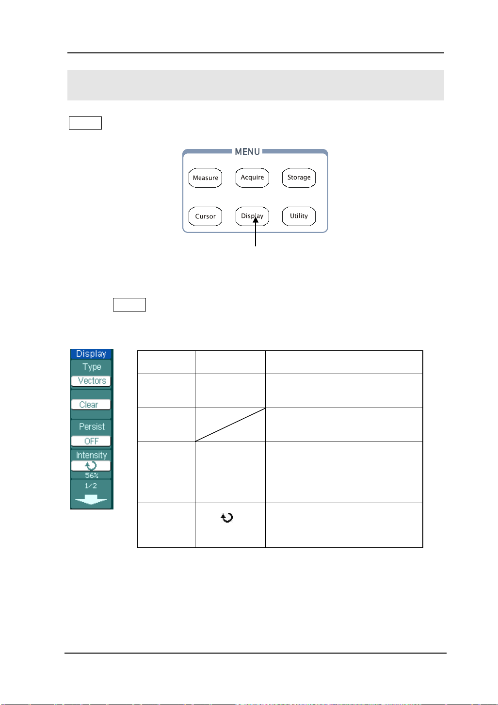
RIGOL
2-57
To Set up the Display System
Display shows the menu button for the display system on the front panel.
Display setup button
Display setup button
Press the Display button to pop up the menu for the settings of the display s ys t em.
Figure 2- 74 Table 2- 43 The Display menu (Page 1/2)
Figure 2- 73
Menu Setting Comments
Type
Clear
persist
Intensity
Vectors
Dots
Infinite
OFF
<
percentage >
Display waveforms as vectors
Display waveforms as dots
Clear all existing waveforms
from screen
The sample points remain
displayed until turn the
persistence “OFF”.
Turn off the persistence function
Set up waveform intensity, the
range is from 0% t o 100%
© 2008 RIGOL Technologies, Inc.
User’s Guide for DS1000E, DS1000D Series

RIGOL
2-58
ates on
he menu will be hidden
Figure 2- 75 Table 2- 44 The Display menu (Page 2/2)
Menu Settings Comments
Display grids and coordin
the screen
Turn off the grids
Grid
Turn off the grids and coordinates
Brightness
Menu
Display
<
1s
2s
5s
10s
20s
percentage >
Infinite
Set up grid brigh t n e s s
Set the time before menu fades
away. T
after the set time of last button
pressing.
Key points:
1. Display type: Display type includes Vector and Dot. In vectors type, the
oscilloscopes connect dots through digital interpolation including both linearity
and sin(x)/x. Sin(x)/x interpolation is s uitable fo r R e al-time sampling and will be
more effective at 50ns or faster time base.
2. Refresh rate: It is an important perfo rma nce of di gital os cillos co pes. It means
the number of display refreshing per second and it will affect the ability to
observe signal.
Adjusting waveform intensity
Default setup of multi-function knob (
© 2008 RIGOL Technologies, Inc.
) is adjusting waveform intensity.
User’s Guide for DS1000E, DS1000D Series

2-59
menu (see
RIGOL
To Store and Recall
Storage shows the menu button for the storage system on the front panel.
Storage setup button
Figure 2- 76
Storage setup button
Press the Storage b u tton to show the menu for the settings of the storage system.
Waveforms and setups can be stored in and recalled from , both internal memory
and external mem ory. The wavefo rm file, setup file, bitmap and CSV file in external
memory can be created and deleted (Note: internal file can be deleted or
overwritten). System supports English/Chinese key in.
Waveform and setup, the menu as following:
Figure 2- 77 Table 2- 45 The Storage menu (For Waveform and Setups)
Menu Settings Comments
Storage
Internal
External
Disk Mana.
Waveform
Setups
Store or recall waveform or
instrument setups
Go to menu for internal memory
operation (see table 2-48)
Go to menu for ext erna l memory
operation (see table 2-49)
Go to disk manage
table 2-50)
© 2008 RIGOL Technologies, Inc.
User’s Guide for DS1000E, DS1000D Series

RIGOL
2-60
Save the current oscilloscope
with the same file name
Go to menu for external
2-49)
Go to disk manage menu
(see table 2-50)
Displayed
Save currently displayed
in memory to CSV file
Save the current oscilloscope
the same file name
Hex
Binary
Save data in hexadecimal format
Save data in binary format
Go to menu for externa l mem ory
operation (see table 2-49)
Go to disk manage menu
(see table 2-50)
Figure 2- 78 Table 2- 46 The Storage menu (For Bitmap)
Menu Settings Comments
Storage Bit map Create or delete bit map files
Para Save
External
ON
OFF
settings in different format
memory operati on(see table
Disk Mana.
Figure 2- 79 Table 2- 47 T he Storage menu (For CSV)
Menu Settings Comments
Storage CSV Create or delete CSV files
Data Depth
Para Save
Maximum
On
Off
waveform data to CSV file
Save the whole waveform data
settings in different format with
LA Data
Type
External
Disk Manage
NOTE
© 2008 RIGOL Technologies, Inc.
[1]
[1]
: Applicable to DS1000D Series only.
User’s Guide for DS1000E, DS1000D Series
Decimal
Save data in decimal format

2-61
Figure 2- 80 Table 2- 48 T he Storage menu (For factory )
Menu Settings Comments
Storage Factory Recall factory setups
Load Recal l factory s etups or files
RIGOL
Disk Mana.
Go to disk manage menu (see
table 2-50)
© 2008 RIGOL Technologies, Inc.
User’s Guide for DS1000E, DS1000D Series

RIGOL
2-62
Set up the location of files in
from the internal memory
to the internal memory
Internal Memory
Press Storage→Internal to enter the following menu.
Figure 2- 81 Table 2- 49 The Inter n al Memory Menu
Menu Settings Comments
Int_00 (S)
.
Internal
.
.
internal memory
Int_09 (N)
Recall wavef orm files and setup
Load
files
location
Save waveform files and setup
Save
files
location
Delete File
(Folder)
Delete the selected location f ile
(folder)
© 2008 RIGOL Technologies, Inc.
User’s Guide for DS1000E, DS1000D Series

2-63
Menu
Settings Comments
(Folder)
Delete the selected location file
(folder)
Back to previous folder
External Memory
Press Storage→External to enter the following menu.
Figure 2- 82 Table 2- 50 The Memory m enu
RIGOL
Path
Current directory
Explorer
New File
(Folder)
Delete File
Load
Path
Directory
File
Switch among Path, Directory and
File
To create new file or folder.
Recall waveform and setup from
USB storage device.
File information.
© 2008 RIGOL Technologies, Inc.
Files
Figure 2- 83
File system display
User’s Guide for DS1000E, DS1000D Series

RIGOL
2-64
, recorded
Disk Manage
Press Storage→Disk Mana to display the following m enu.
Figure 2- 84 Table 2- 51 The Disk Manage Menu (Page 1/2)
Menu Settings Comments
Path
Explorer
New folder
Delete File Delete fil e
Directory
File
Switch among Path, Directory and
File
To create new folder( same as new
fil es, se e table 2-13)
Load
Figure 2- 85 Table 2- 52 The Disk Manage Menu (Page 2/2)
Menu Settings Comments
Rename To rename a file (see table 2-52)
Disk info Display disk information
Recall waveform, setup
waveform, Pass / Fail file
© 2008 RIGOL Technologies, Inc.
User’s Guide for DS1000E, DS1000D Series

2-65
Rename
Press Storage→Disk Manage.→Rename to go to the following menu.
Figure 2- 86 Table 2- 53 The Rename Menu
Menu Settings Comments
To move the cursor up
To move the cursor down
To delete chosen letter
OK Rename the f ile
RIGOL
Figure 2- 87
Rename the file
Key Points:
Factory: The oscilloscope has default settings and can be recalled at anytime.
Memory location: Specify memory location to save/recall the waves and setups.
Load: Recall saved waveforms, setups and default settings.
Save: Save wave f orms and setups.
© 2008 RIGOL Technologies, Inc.
User’s Guide for DS1000E, DS1000D Series

RIGOL
2-66
NOTE:
1. Select Save stores not only the waveforms, but also the current settings.
2. To ensure the setups being saved properly, only after the settings are changed
for more than 5 seconds can the user turn off the instrument. The oscilloscope
can store 10 settings permanently and can restore at anytime.
© 2008 RIGOL Technologies, Inc.
User’s Guide for DS1000E, DS1000D Series

RIGOL
2-67
(OFF)
(More lan guages m ay be adde d in la ter
To Set up the Utility System
Utility shows the menu button for the Utility on the front panel.
Figure 2- 88
Utility setup button
Press the Utility button to pop up the menu for the settings of the Utility system.
Figure 2- 89 Table 2- 54 The Utility Menu (Page 1/3)
Utility setup button
Menu Setting Comments
I/O setting Setup I/O configuration
Sound
Counter
Language
© 2008 RIGOL Technologies, Inc.
User’s Guide for DS1000E, DS1000D Series
(ON)
OFF
ON
简体中文
繁体中文
English
日本語
François
…
Switch beeper sound on/o ff
Turn off Frequency Counter
Turn on Frequency Counter
Select languages
firmware versions)

RIGOL
2-68
Menu
Settings
Comments
Figure 2- 90 Table 2- 55 The Utility menu (Page 2/3)
Menu Settings Comments
Pass/Fail Setup Pass/Fail test
Record Setup Waveform Recorder
Print set Setup printing
Figure 2- 91 Table 2- 56 The Utility menu (Page 3/3)
Preference Go to preference menu
Self-Cal Execute Self-calibration
System Info Display system informat ion
Special Mode Lock/Unlock Lock the keybo ar d
NOTE:
Self-Calibration: Oscilloscope will calibrate parameter of vertical system (CH1,
CH2, and Ext), horizontal system and trigger system.
© 2008 RIGOL Technologies, Inc.
User’s Guide for DS1000E, DS1000D Series

2-69
Menu
Display Comments
baud rate as
I/O setting
Press Utility→I/O setting to go to the following menu.
Figure 2- 92 Table 2- 57 The I/O Setup Menu
RIGOL
RS-232
Baud
USB
Device
GPIB# 0-30 Set the GPIB address
[1]
300
.
.
38400
Computer
PictBridge
Set RS-232
300, 2400, 4800, 9600, 19200
or 38400.
Set the USB device
[1]
NOTE
: Users must set the USB device type manually first to ensure the
equipment connected is the same as the settings when switch the device from
computer (PictBridge printer) to PictBridge printer (computer) by the USB Device
port.
© 2008 RIGOL Technologies, Inc.
User’s Guide for DS1000E, DS1000D Series

RIGOL
2-70
Language
The oscilloscopes have multi-language user menu, choose as your desire.
Press Utility→Language to select the language.
Figure 2- 93
The Language menu
Please use the fourth menu button or use the knob
need.
to select the language you
© 2008 RIGOL Technologies, Inc.
User’s Guide for DS1000E, DS1000D Series
 Loading...