

Page 1

RIGOL
Installation Guide
RM-DS-1 Rackmount Kit
DS1000 Series, DS1000CA Series, DS1000E Series, DS1000D Series
Digital Oscilloscope
May 2009
RIGOL Technologies, Inc.
Page 2

RIGOL
Copyright
© 2009 RIGOL Technologies, Inc. All Rights Reserved.
Publication Number
RKI02100-1110
Trademark Information
RIGOL is registered trademark of RIGOL Technologies, Inc.
Notices
RIGOL products are protected by patent law in and outside of P.R.C..
RIGOL Technologies, Inc. reserves the right to modify or change parts of or all the specifications
and pricing policies at company’s sole decision.
Information in this publication replaces all previously corresponding material.
RIGOL shall not be liable for losses caused by either incidental or consequential in connection
with the furnishing, use or performance of this manual as well as any information contained.
Any part of this document is forbidden to copy or photocopy or rearrange without prior written
approval of RIGOL.
Installation Guide for RM-DS-1 Rackmount Kit 1
Page 3
RIGOL
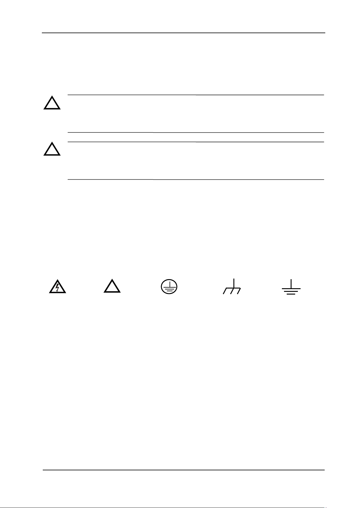
!
!
Hazardous
Voltage
Refer to
Instructions
!
Chassis
Ground
Test
Ground
Protective
Earth
Terminal
Safety Terms and Symbols
Terms in this Guide. These terms may appear in this manual:
WARNING
Warning statements indicate the conditions or practices that could result in injury or loss of
life.
CAUTION
Caution statements indicate the conditions or practices that could result in damage to this
product or other property.
Terms on the Product. These terms may appear on the product:
DANGER indicates an injury or hazard that may immediately happen.
WARNING indicates a potential injury or hazard that may happen.
CAUTION indicates that a potential damage to the instrument or other property might occur.
Symbols on the Product. These symbols may appear on the product:
Installation Guide for RM-DS-1 Rackmount Kit 2
Page 4

RIGOL
Figure
No.
Name
Qty
Part Number
Description
1-1
Front Panel
1
RM-DS-1-01
1-2
Support Board
1
RM-DS-1-02
1-3
Left Plate
1
RM-DS-1-03
1-4
Right Plate
1
RM-DS-1-04
1-5
Rear Fixed Belt
1
RM-DS-1-05
1-6
Rear Fixed
Bracket
1
RM-DS-1-06
2-1
M4 Screw
16
RM-SCREW-01
M4*6 Phil-Slot Pan Head Machine Screw Nail
2-2
M6 Screw
4
RM-SCREW-02
M6*20 Phil-Slot Pan Head Machine Screw Nail
2-3
M6 Nut
4
RM-SCREW-03
M6*4 Square Machine Female Screw Contain
Lock Blade
Kit Overview
The kit is used to mount your DS1000 Series, DS1000CA Series, DS1000E Series, DS1000D Series
Oscilloscope into a standard 19-inch rack.
Kit Parts List
Table 1 Kit Parts List
Figure 1: Kit Parts
Installation Guide for RM-DS-1 Rackmount Kit 3
Page 5

2-1 2-2 2-3
Figure 2: Screw Models
RIGOL
Space Requirements for Installation
Following requirements must be fulfilled by the machine cabinet in which the instrument is mounted.
1. The machine cabinet should be a standard 19-inch.
2. At least 4U spaces (177.8mm) have to be provided by machine cabinet.
3. The depth inside the machine cabinet should not be less than 165mm.
Figure 3: Dimension of Instrument with Rack Adapter Installed
Installation Guide for RM-DS-1 Rackmount Kit 4
Page 6

RIGOL
NO.
Name
Description
1
Phillips screwdriver
PH2 Phillips screwdriver
!
Installation Instructions
This section will introduce you how to mount the DS1000 series Oscilloscope into a standard 19-inch
machine cabinet.
Installation Tools
Table 2 Installation Tools List
CAUTION
Only authorized personnel can perform the installation, improper operation may cause
damage to the instrument or incorrect installation.
Installation Procedures
1. Install the left and right plate: aim the detents of both right and left plate at the openings on
support board and insert selectively, then fix them using four M4 bolts.
Installation Guide for RM-DS-1 Rackmount Kit 5
Figure 4: Installation of Left and Right Plate
Page 7

RIGOL
2. Mount front panel: aim the opening of front panel at left and right plate-fixed and fix them using
six M4 bolts.
Figure 5: Installation of Front Panel
3. Place the instrument: first, put the instrument onto the support board and then generally slide it
into right position down the baby hem on either side, exposing the front of instrument from the
opening of front panel.
Figure 6: Place the Instrument
Installation Guide for RM-DS-1 Rackmount Kit 6
Page 8

RIGOL
4. Fix the instrument: first, put by the hanging ring to avoid blocking out the rear fixed belt, then,
using six M4 bolts to fix both the rear fixed brackets and rear fixed belt on the support board in
connection with the instrument.
Figure 7: Fix the instrument
5. Loading into machine cabinet: mount the rack with instrument-fixed onto a standard 19-inch
machine cabinet respectively using 4 M6 bolts and square nuts and then put the hanging ring
back in position.
Figure 8: Loading into machine cabinet
Installation Guide for RM-DS-1 Rackmount Kit 7
Page 9

RIGOL
Power input
Ship type switch
Power source
Notice
1. The rack holds a height of 4U, and the holes those in compliance with the arrow direction are the
mounting holes for rack.
Figure 9: Holes for rack
2. The rack has a power cord that was connected with the power input terminal and the power
source terminal in series. A ship type switch is used to turn ON or OFF the instrument once the
power switch above the instrument has been pressed down.
Installation Guide for RM-DS-1 Rackmount Kit 8
Figure 10: Power Cord Connection of Rack
Page 10

RIGOL
Contact Us
If you have any problem or requirement during using our products, please contact RIGOL
Technologies, Inc. or your local distributors.
Domestic: Please call
Tel: (86-10) 8070 6688
Fax: (86-10) 8070 5070
Service & Support Hotline: 800 810 0002
9:00 am –5: 00 pm from Monday to Friday
Or by e-mail:
service@rigol.com
Or mail to:
RIGOL Technologies, Inc.
156# CaiHe Village, ShaHe Town, ChangPing District, Beijing, China
Post Code: 102206
Overseas: Contact the local RIGOL distributors or sales office.
For the latest product information and service, visit our website: http://www.rigolna.com/
Installation Guide for RM-DS-1 Rackmount Kit 9
 Loading...