

Page 1

RIGOL
User’s Guide
DS1000B Series Digital Oscilloscopes
DS1074B,DS1104B,DS1204B
Aug. 2016
RIGOL TECHNOLOGIES, INC.
Page 2

Page 3

RIGOL
Guaranty and Declaration
Copyright
© 2009 RIGOL TECHNOLOGIES, INC. All Rights Reserved.
Trademark Informat ion
RIGOL is registered trademark of RIGOL TECHNOLOGIES, INC.
Publicatio n Number
UGA04125-1210
Notices
RIGOL products are covered by P.R.C. and foreign patents, issued and
pending.
RIGOL rese rves the right to modify or change pa rt s of or all the specifications
and pricing policies at the company’s s ole de cision .
Information in this publication replaces all previously released materials.
Information in this publication is subject to change without notice.
RIGOL shall not be liable for either incidental or consequential losses in
connection with the furnishing, use, or performance of this manual, as well as
any information contained.
Any part of this document is forbidden to be copied, photocopie d, or rearranged
without prior written approval of RIGOL.
Product Certification
RIGOL guarantees this pr oduct conforms to the nati onal and indust rial standar ds in
China as well as the ISO9001:2008 standard and the ISO14001:2004 standard.
Other international standard conformance certification is in progress.
Contact Us
If you have any problem or requirement when using our products or this manual,
please contact RIGOL.
E-mail: service@rigol.com
Website: www.rigol.com
User’s Guide for DS1000B Series
I
Page 4

RIGOL
Safety Notices
Please review the following safety precautions carefully before putting the
instrument into operation so as to avoid any personal injury or damage to the
instrument and any product connected to it. To prevent potential hazards, please
follow the instructions specif ied in this manual to use the instrument properly.
Use Proper Power Cord.
Only the exclusive power cord designed for the instrument and authorized for use
within the local country could be used.
Ground the Instrument.
The instrument is grounded th rough t he Protectiv e E arth lea d of the p ower co rd. To
avoid electr ic shock, connect the earth term i na l of the power cord to the Pro tec t i ve
Earth terminal before connecting any input or output terminals.
Connect the Probe Correctly.
If a probe is used, the probe ground lead must be connected to earth ground. Do
not connect the ground lead to high voltage. Improper way of connection could
result in dangerous voltages being present on the connectors, controls or other
surfaces of the oscilloscope and probes, which will cause potential hazards for
operators.
Observe All Terminal Ratings.
To avoid fire or shock hazard, observe all ratings and markers on the instrument and
check your manual for more information about ratings before connecting the
instrument.
Use Proper Overvoltage Protection.
Ensure that no overv oltage (such as that cause d by a bolt of lightnin g) can reach the
product. Otherwise, the operator might be exposed to the danger of an electric
shock.
Do Not Operate Without Covers.
Do not operate the instrument with covers or panels removed.
II
User’s Guide for DS1000B Series
Page 5

RIGOL
Do Not Insert Anything Into the Air Outlet.
Do not insert anything into the air outlet to avoid damage to the instrument.
Use Proper Fuse.
Please use the specified fuses.
Avoid Circuit or Wire Exposure.
Do not touch exposed junctions and components when the unit is powered on.
Do Not Operate With Suspected Failures.
If you suspect that any damage may occur to the instrument, have it inspected by
RIGOL authorized personnel before further operations. Any maintenan ce,
adjustment or replacement especially to circuits or accessories must be performed
by RIGOL authorized personnel.
Provide Adequate Ventilation.
Inadequate ventilation may cause an increase of temperature in the instrument,
which would cause damage to the instrument. So please keep the instrument well
ventilated and inspect the air outlet and the fan regularly.
Do Not Operate in Wet Conditions.
To avoid short circuit inside the instrument or electric shock, never operate the
instrument in a humid environment.
Do Not Operate in an Explosive Atmosphere.
To avoid personal injuries or damage to the instrument, never operate t he
instrument in an explo sive atm ospher e.
Keep Instrument Surfaces Clean and Dry.
To avoid dust or moisture from affecting the performance of the instrument, keep
the surfaces of the instrument clean and dry.
Prevent Electrostatic Impact.
Operate the instr ument in an electrostatic discharge protective en vironment to avoid
damage induced by static discharges. Always ground both the inter nal and external
conductors of cables to release static before making connections.
Use the Battery Properly.
Do not expose the battery (if available) to high temperature or fire.
User’s Guide for DS1000B Series
III
Page 6

RIGOL
Keep it out of the reach of children. Improper change of a battery (lithium bat t ery)
may cause an explosion. Use the RIGOL specified battery only .
Handle with Caution.
Please handle with care during transportation to avoid damage to keys, knobs,
interfaces, and other parts on the panels.
The disturbance test of all the models meet the limit values of A in the
standard of EN 61326: 1997+A1+A 2+A3, but can’t meet the limit values
of B.
Measurement Category
The DS1000B series Digita l Oscilloscope is intende d to be used f or measu rement s in
Measurement Category I.
Measurement Category
Definitions
Measurement Category I is for measurements performed on circuits not directly
connected to MAINS. Examples are measuremen t s on circuits not derived from
MAINS, and specially protected (inte rnal ) MAI NS de riv ed circuits. In the latter case,
transient stresses are variable; for that reason, the transient withstand capability of
the equipment is made known to the user.
WARNING
IEC Measurement Category I, the input terminals may be connected to circuit
terminal in IEC Category I installations for voltages up to 300 VAC. To avoid the
danger of electric shock, do not connect the inputs to circuit’s voltages above 300
VAC.
Transient overvoltage is also present on circuits that are isolated from mains. The
DS1000B series Digital Oscilloscopes is designed to safely withstand occasional
transient ove rvolta ge up to 1000 Vpk. Do not use thi s equipment to measure circuit s
where transient overvoltage could exceed this level.
IV
User’s Guide for DS1000B Series
Page 7
RIGOL
Hazardous
Safety
Protective
Chassis
Test
Safety Notices and Symbols
Safety Notices in this Manua l:
WARNING
Indicates a potentially hazardous situation or practice which, if not
avoided, will result in serious injury or death.
CAUTION
Indicates a potentially hazardous situation or practice which, if not
avoided, could result in damage to the product or loss of im portant data.
Safety Terms on the Product:
DANGER It calls attention to an operation, if not correctly pe rformed, could
result in injury or hazard immediately.
WARNING It calls attention to an operation, if not correctly pe rformed, could
result in
CAUTION It calls attention to an operation, if not correctly pe rformed, could
result in
product.
Safety Symbols on the Product:
potential injury or hazard.
damage to the product or other devices connected to the
Voltage
Warning
User’s Guide for DS1000B Series
Earth
Terminal
Ground
Ground
V
Page 8

RIGOL
Allgemeine Sicherheits Informationen
Überprüfen Sie diefolgenden Sicherheitshinweise
sorgfältigumPersonenschädenoderSchäden am Gerätundan damit verbundenen
weiteren Gerätenzu vermeiden. Zur Vermeidung vonGefahren, nutzen Si e bitte das
Gerät nur so, wiein diesem Handbuchangegeben.
Um Feuer oder Verletzungen zu vermeiden, verwenden Sie ein
ordnungsgemäßes Netzkabel.
Verwenden Sie für dieses Gerät nur das für ihr Land zugelass ene u nd genehm igte
Netzkabel.
Erden des Gerätes.
Das Gerät ist durch den Schutzleiter im Netzkabel geerdet. Um Gefahren durch
elektrischen Schlag zu vermeiden, ist es unerlässlich, die Erdung durchzuführen.
Erst dann dürfen weitere Ein- oder Ausgänge verbunden werden.
Anschluss einesTastkopfes.
Die Erdungsklemmen der Sonden sindauf dem gleichen Spannungspegel des
Instruments geerdet. SchließenSie die Erdungsklemmen an keine hohe Spannung
an.
Beachten Sie alle Anschlüsse.
Zur Vermeidung von Feuer oder Stromschlag, beachten Sie alle Bemerkungen und
Markierungen auf dem Instrument. Befolgen Sie die Bedienungsanleitung für
weitere Informationen, bevor Sie weitere Anschlüsse an das Instrument legen.
Verwenden Sie einen geeigneten Überspannungsschutz.
Stellen Sie sicher, daß keinerlei Überspannung (wie z.B. durch Gewitte r verurs acht)
das Gerät erreichen kann. Andernfallsbestehtfür den Anwender die
GefahreinesStromschlages.
Nicht ohne Abdeckung einschalten.
Betreiben Sie das Gerät nicht mit entfernten Gehäuse-Abdeckungen.
Betreiben Sie das Gerät nicht geöffnet.
Der Betrieb mit offenen oder entfernten Gehäuseteilen ist nicht zulässig. Nichts in
VI
User’s Guide for DS1000B Series
Page 9

RIGOL
entsprechende Öffnungen stecken (Lüfter z.B.)
Passende Sicherung verwenden.
Setzen Sie nur die spezifikationsgemäßen Sicherungen ein.
Vermeiden Sie ungeschützte Verbindungen.
Berühren Sie keine unis olierten Verbindungen oder Baugruppen, während das Gerät
in Betrieb ist.
Betreiben Sie das Gerät n ic h t im Fehlerfa ll .
Wenn Sie am Gerät einen Defekt vermuten, sorgen Sie dafür, bevor Sie das Gerät
wieder betreiben, dass eine Untersuchung durch RIGOL autorisiertem Personal
durchgeführt wird. Jedwede Wartung, Einstellarbeiten oder Austausch von Teilen
am Gerät, sowie am Zubehör dürfen nur von RIGOL autorisiertem Perso nal
durchgeführt werden.
Belüftung sicherstellen.
Unzureichende Belüftung kann zu Temperaturanstiegen und somit zu thermischen
Schäden am Gerät führen. Stellen Sie deswegen die Belüftung sicher und
kontrollieren regelmäßig Lüfter und Belüftungsöffnungen.
Nicht in feuc h te r Um g ebung betre iben.
Zur Vermeidung von Kurzschluß im Geräteinneren und Stromschlag betreiben Sie
das Gerät bitte niemals in feuchter Umgebung.
Nicht in explosiver Atmosphäre betreiben.
Zur Ve rm e idung von P e rs onen- und Sachschäden ist es unumgängli ch, das Ger ät
ausschließlich fernab jedweder explosiven Atmosphäre zu betreiben.
Geräteoberflächen sauber und trocken halten.
Um den Einfluß von Staub und Feuchtigkeit aus der Luft auszuschließen, halten Sie
bitte die Geräteoberflächen sauber und trocken.
Schutz gegen elektrostatische Entladung (ESD).
Sorgen Sie für eine elektrostatisch geschützte Umgebung, um somit Schäden und
Funktionsstörungen durch ESD zu vermeiden. Erden Sie vor dem Anschluß immer
Innen- und Außenleiter der Verbindungsleitung, um statische Aufladun g zu
entladen.
User’s Guide for DS1000B Series
VII
Page 10

RIGOL
Die richtige Verwendung desAkku.
Wenneine Batterieverwendet wird, vermeiden Sie hohe Temperaturen bzw. Feuer
ausgesetzt werden. Bewahren Sie es außerhalbder Reichweitevon Kindern auf.
Unsachgemäße Änderung derBat t e ri e (Anmerkung: Lithium-Batterie) kann zu einer
Explosion führen. VerwendenSie nur von RIGOL angegebenenAkkus.
Sicherer Transport.
Transportieren Sie das Gerät sorgfältig (Verpackung!), um Schäden an
Bedienelementen, Anschlüssen und anderen Teilen zu vermeiden.
VIII
User’s Guide for DS1000B Series
Page 11
RIGOL
Sicherheits Begriffe und Symbole
Begriffe in diesem Guide:
WARNING
Die Kennzeichnung WARNING beschreibt Gefahrenq ue llen die leibliche
Schäden oder den Tod von Personen zur Folge haben können.
CAUTION
Die Kennzeichnung Caution (Vorsicht) beschreibt Gefahrenquellen die
Schäden am Gerät hervorrufen können.
Begriffe auf dem Produkt:
DANGER weist auf eine Verletzung oder Gefährdung hin, die sof ort
geschehen kann.
WARNING weist auf eine V erletzung oder Gefährdung hin , die möglicherweise
nicht sofort geschehen.
CAUTION weist auf eine Verletzung oder Gefährdung hin und bedeutet, dass
eine mögliche Beschädigung des Instruments oder anderer
Gegenstände auftreten kann.
Symbole auf dem Produkt:
Gefährliche
Spannung
SicherheitsHinweis
Schutz-erde Gehäusemasse Erde
User’s Guide for DS1000B Series
IX
Page 12

RIGOL
General-Purpose Oscilloscopes
The introduction of this document contains three types of DS1000B series
oscilloscope: DS1074B, DS1104B and DS1204B
RIGOL DS1000B series digital oscilloscopes with four analog channels in
connection with an external trigger channel are designed to capture multi ple signals
and meet the needs of measurement along with its e xcellent performa nce, pow erful
functions.
The instrument is designed for 2GSa/s maximum real-time sample rate, 50GSa/s
maximum equivalent sample rate and 20 0 MHz maximum ba n dw idth. Besides,
abundant trigger modes, math and acquire functions enable it easy to capture and
analyze waveforms, also, Auto button is available to display a signal automatically.
What’s more, the laconic and clear panel in line with tradition and the intuitive on
the panels make instrument operation easy and convenient, as well as the LCD,
interface and buttons are all friendly and clear, ma king o peration m ore comfor table.
Main Features:
Four Channels, Bandwidth of per channel:
200MHz: DS1204B
100MHz: DS1104B
70MHz: DS1074B
2GSa/s real-time s ampling rat e and 50GSa/s equivalent sampling rate.
Color TFT 5.7 inch LCD, 320×240 pixels resolution.
USB storage and PictBridge printing.
Available to interconnect with RIGOL signal generator seamlessly.
Adjustable waveform intensity, more effective waveform viewing.
One-touch automatic setup, ease of use (AUTO).
Storage and recurrence of Waveforms and setups, supports CSV, 8 or 24 bits
bitmap and PNG format.
Delayed Scan Function, easy to give at tention to bot h details and o ver view of a
waveform.
22 Automatic measurements.
Automatic cursor tracking measurements.
Waveform recor de r, record and repla y dynamic waveforms.
X
User’s Guide for DS1000B Series
Page 13

RIGOL
Built-in FFT function.
Digital filters, includes LPF, HPF, BPF, BRF.
Pass/Fail detection Function, optically isolated Pass/Fail output.
Addition, Subtract and Multiply Mathematic Functions of waveforms.
Advanced trigger types include: Edge, Video , Pulse w idth, Pattern, Alternative.
Adjustable trigger sensitivity.
Multiple Language User Interface.
Pop-up menu makes it easy to read and easy to use.
Built-in help systems with multinational languages.
Easy-to-use file system supports Chinese & English characters file name input.
Conform to LXI consortium instrument standard class C.
User’s Guide for DS1000B Series
XI
Page 14

RIGOL
Document Overview
Chapter 1 Quick Start
To introduce the panls and menus to help users to realize the base operations.
Chapter 2 Operating Your Oscilloscope
More details to help users to understand the functions and measurements of
instrument deeply.
Chapter 3 Application Examples
To show the measurement functions directly by application examples.
Chapter 4 Troubleshooting
Provide you troubleshooting to solve the problems during operating.
Chpter 5 Specifications
List common specifications and characteristics of the oscilloscope.
Chapter 6 Appendix
Information about accessories, warranties, services and supports and the like.
XII
User’s Guide for DS1000B Series
Page 15

RIGOL
Contents
Guaranty and Declaration ........................................................................ I
Safety Notices ........................................................................................ II
Safety Notic e s an d Symbols .................................................................... V
Allgemeine Sicherheits Informationen................................................... VI
Sicherheits Begriffe und Symbole .......................................................... IX
General-Purpose Oscilloscopes ............................................................... X
Document Overview ............................................................................ XII
Chapter 1 Quick Guide ....................................................................... 1-1
General Inspect .................................................................................... 1-2
Panels and User Interface ...................................................................... 1-3
Functional Check ................................................................................... 1-7
To Compensate the Probes .................................................................... 1-9
To Display a Signal Automatically ......................................................... 1-10
To Understand the Vertical System ....................................................... 1-11
To Understand the Horizontal System ................................................... 1-13
To Understand the Trigger System ....................................................... 1-15
To Understand the Quick Function ........................................................ 1-17
Chapter 2 Operating Your Oscilloscope ............................................. 2-1
To Set up the Vertical System ................................................................ 2-2
Channel Settings ............................................................................ 2-4
Math Function .............................................................................. 2-14
REF Function ................................................................................ 2-20
To Set up the Horizontal System........................................................... 2-28
Delayed S can ............................................................................... 2-31
X-Y Format ................................................................................... 2-32
To Set up the Trigger System ............................................................... 2-33
Edge Trigger ................................................................................ 2-34
Pulse Width Trigger ...................................................................... 2-35
Video Trigger ............................................................................... 2-36
Pattern Trigger ............................................................................. 2-39
Alternative Trigger ........................................................................ 2-41
Trigger Settings ............................................................................ 2-44
User’s Guide for DS1000B Series
XIII
Page 16

RIGOL
XIV
To Set up the Sampling System ............................................................ 2-50
To Set up the Display System ............................................................... 2-54
To Store and Recall ............................................................................. 2-57
To Set up the Utility ............................................................................ 2-66
The I/O Setup .............................................................................. 2-68
Language .................................................................................... 2-76
Pass/Fail ...................................................................................... 2-77
Waveform Recorder ...................................................................... 2-80
Print Setting ................................................................................. 2-84
Self-Calibration ............................................................................. 2-88
System Informat i on ...................................................................... 2-89
Date and Time ............................................................................. 2-91
To Measure Automatically .................................................................... 2-92
Quick Measurement Setup ............................................................. 2-94
Delay/Phase Setup ........................................................................ 2-95
Voltage Measurements .................................................................. 2-96
Time Measurements ...................................................................... 2-98
To Measure with Cursors ................................................................... 2-101
Manual Mode ............................................................................. 2-102
Track Mode ................................................................................ 2-104
Auto mode ................................................................................. 2-106
To Use Run Control Buttons ............................................................... 2-107
Chapter 3 Application Examples ....................................................... 3-1
Example 1: Taking Simple Measurements ................................................ 3-1
Example 2: View a Signal Delay Caused by a Circuit ................................. 3-2
Example 3: Capture a Single-Shot Signal ................................................. 3-3
Example 4: To Reduce the Random Noise on a Signal ............................... 3-4
Example 5: Making Cursor Measurements ................................................ 3-6
Example 6: The Application of the X-Y operati on ...................................... 3-8
Example 7: Triggering on a Video Signal ............................................... 3-10
Example 8: FFT Cursor Measurement .................................................... 3-12
Example 9: Pass/Fail Test .................................................................... 3-13
Chapter 4 Troubleshooting ............................................................... 4-1
Chapter 5 Specifications ................................................................... 5-1
Technical Specifications ................................................................... 5-2
General Specifications ..................................................................... 5-6
Chapter 6 Appendixes ....................................................................... 6-1
User’s Guide for DS1000B Series
Page 17

RIGOL
Appendix A: DS1000B series Accessories ................................................. 6-1
Appendix B: Warranty ........................................................................... 6-2
Appendix C: Care and Cleaning .............................................................. 6-3
Index ...................................................................................................... 1
User’s Guide for DS1000B Series
XV
Page 18

Page 19

Chapter 1 Quick Guide
This chapter covers the following topics:
General Inspect
Panels and User Interface
Functional Check
To Compensate the Probes
To Display a Signal Automatically
To Understand the Vertical System
To Understand the Horizontal System
RIGOL
To Understand the Trigger System
To Understand the Quick Function
User’s Guide for DS1000B Series
1-1
Page 20

RIGOL
General Inspect
After receiving a new DS1000B series oscilloscope, please inspect the instrument as
follows:
1. Inspect the shipping container for damage.
Keep the damaged shipping container or cushioning material until the contents
of the shipment have been checked for completeness and the instrument has
passed both ele ctrical and mechanical test.
The consigner or carrier shall be liable for the damage to instrument resulting
from shipment, without free maintenance or replacement by RIGOL.
2. Inspect the instrument.
In case of any damage, or defect, or failure, notify your RIGOL Sales
Representative.
3. Check the accessories.
Accessories supplied with the instrument are listed in "Appendix A: DS1000B
series Accessories" in this guide.
If the contents are incomplete or damaged, please notify your RIGOL Sales
Representative.
1-2
User’s Guide for DS1000B series
Page 21
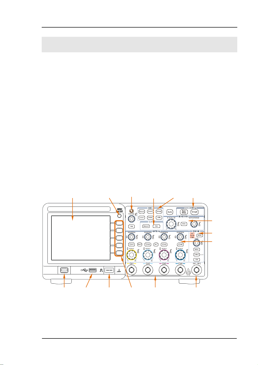
LCD Off Menu Knob Button Menu Control
Power USB Probe Menu Analog Signal EXT TRIG
RIGOL
Panels and User Interface
Being familiar with the operation panels is the f irst priority when you get a new
DS1000B series digital oscilloscope. This chapter will bring you a brief introduction
and description of the panels and functions of oscilloscope, which can help users to
know well about the instrument in a short time.
Front Panel
Figure 1-1, the front Panel; the knobs are used most often and are similar to the
knobs on other oscilloscopes. There are f ive gr ey buttons defined a s No.1 to No.5
from up to bott om on the right side of the displa y which a re menu ope rating buttons.
The buttons not only all ow you to use s ome of the f unctions directly but also bring up
soft button menus on the screen, which enable the access to many measurement
features associated with the advanced functions, mathematics, and reference or to
run control features.
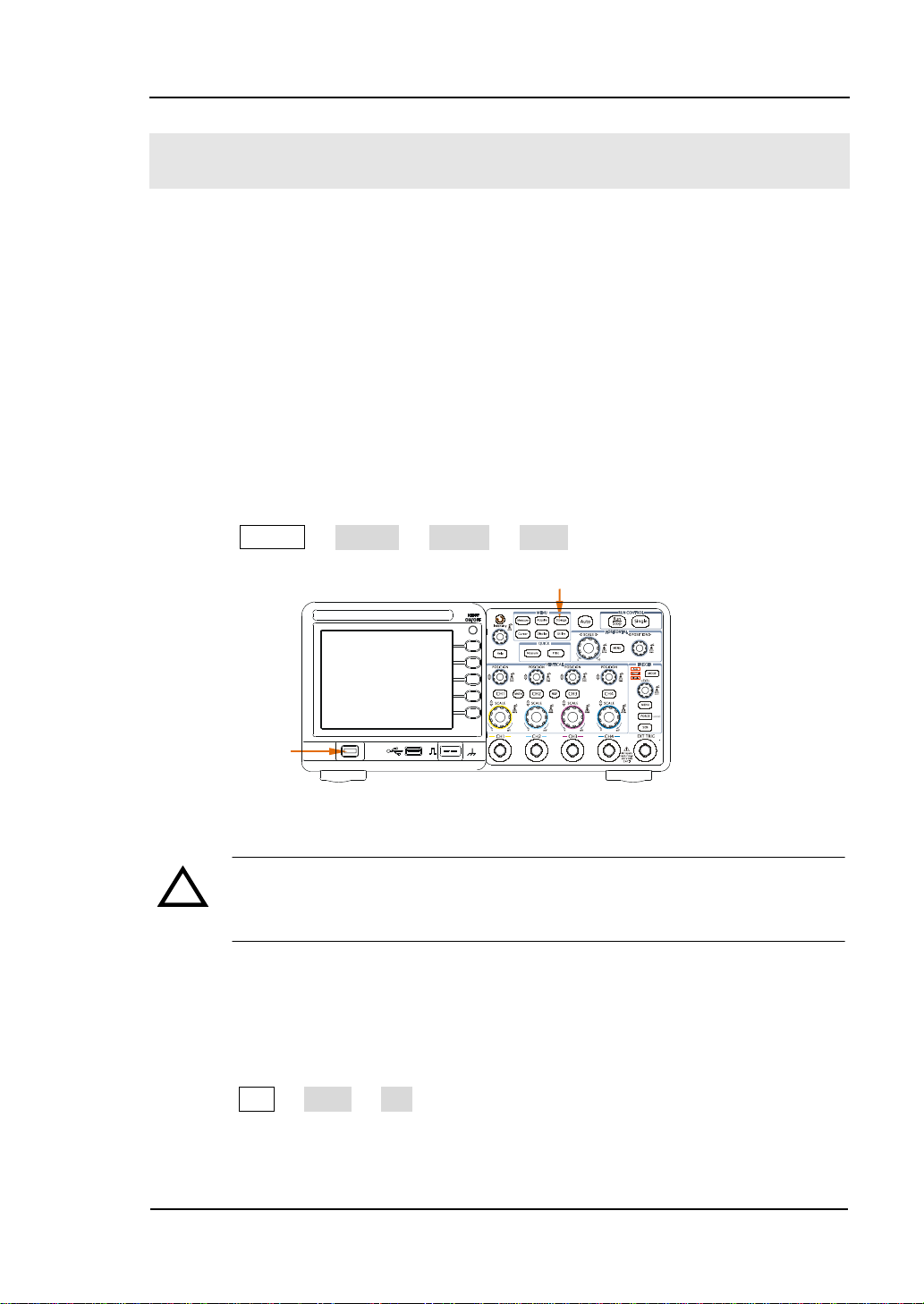
Turn On/ Multi-Function Quick Function Run
Switch Host Compensator Buttons Channels Channel
Figure 1-1 Front Panel Overview
User’s Guide for DS1000B Series
Horizontal
Trigger
Vertical
1-3
Page 22
RIGOL
Front Panel Interfaces:
USB Host: Con nect DS1000B with external USB devices when the oscilloscope is
regarded as “Host Devi ce”, such as connecting a USB flash device.
Analog Signal Channels: Four channels are provided: CH1, CH2, CH3 and CH4.
EXT TRIG Input: It is applied to input external trigger signal.
NOTE: There are two USB Host ports respectively on the front and rear panel.
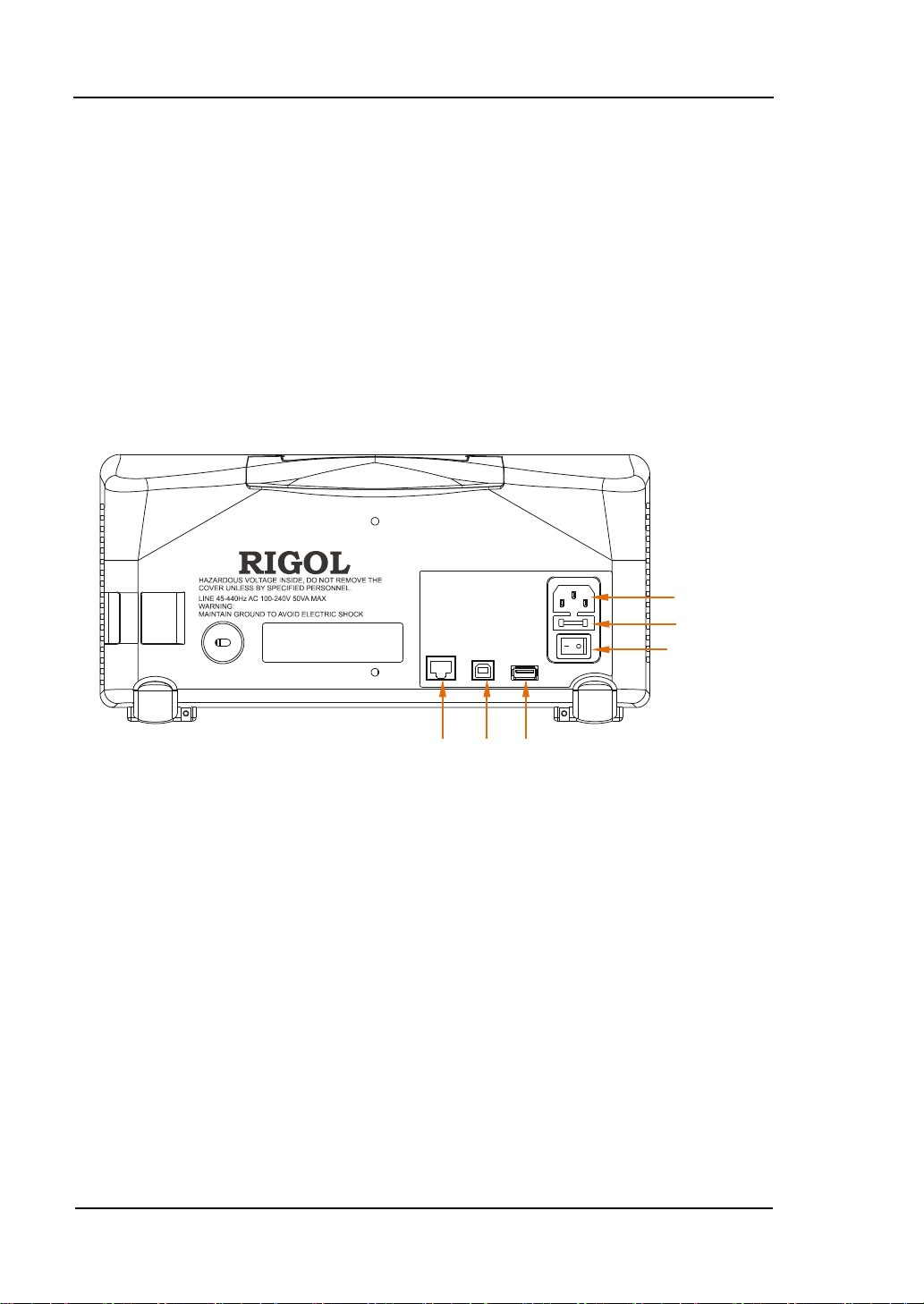
Rear Panel
①
②
③
④ ⑤ ⑥
Figure 1-2 Rear Panel Overview
Rear Panel of DS1000B contains the fo llo wing parts:
① Power Supply: Input power supply to the instrument.
② Fuse: 250V, T2A
③ Power Switch: Turn on or off the power source.
④ LAN: Enable users to set up network by LAN port.
⑤ USB Device: Connect DS1000B with external USB devices wh en the
oscilloscope is regarded as “Slave Device”. For exa mpl e: connect with PC for
remote contr ol .
⑥ USB Host: Connect DS1000B with external USB devices when the
oscilloscope is regarded as “Host Device”, such as connecting a USB flash
device.
1-4
User’s Guide for DS1000B series
Page 23
RIGOL
Notation definitions in this Manual:
Throughout this guide, notation symb ols of buttons a nd knobs are the sa me of those
on front-panel.
A box around the name of the key denotes MENU function buttons on
front-panel, such as Measure.
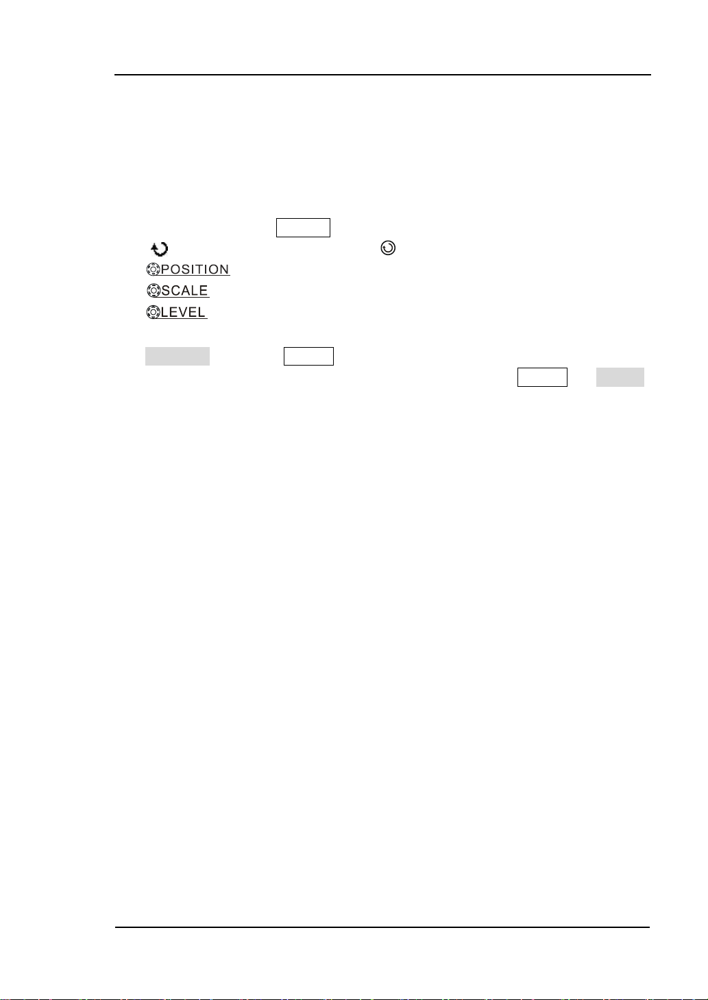
( ) denotes the multi-function knob .
denotes the five POSITION knobs.
denotes the five SCALE knobs.
denotes the LEVEL knob.
The name with a drop shadow denotes the menu operating key, such as
Waveform soft key in Storage menu.
Arrow “→” is used to divide operation steps. Such as: Storage → Storage,
indicates press “Storage” button on the front panel, then press “Storage” menu.
User’s Guide for DS1000B Series
1-5
Page 24
RIGOL
Menu
CH1
CH3
Run
CH2
CH4
Trigger
Symbol
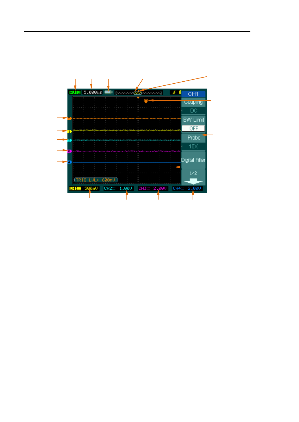
User Interface
Status Timebase
U-Disk Location of Waveform Trigger Point
Connected Window in Memory in Memory
CH1 Volts/div CH2 Volts/div CH3 Volts/div CH4 Volts/div
Figure 1-3 User Interface Overview
Trigger Point in
Waveform
Window
Waveform
Display
Window
1-6
User’s Guide for DS1000B series
Page 25
RIGOL
Power
Functional Check
Perform this quick functional check to verify that the instrument is operating
correctly.
1. Turn on the instrument
Use the power cord designed for the oscilloscope only to connect the instru ment
and AC power which delivers 100 to 240 VAC
power switch to turn on the instruments, waiting until the display shows the
waveform window.
2. Recall factory setting
Press Storage → Storage → Factory → Recall, to recall factory setting.
Storage Button
Switch
, 45Hz to 44 0 Hz. Press the
RMS
Figure 1-4 Button explanation
WARNING
!
To avoid electric shock, be sure the oscilloscope is prope rl y grounded .
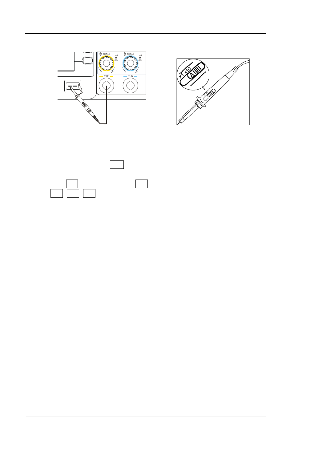
3. Input a signal to a channel of the oscilloscope
Push BNC plug of probe into CH1 BNC connector, then twist the BNC cable to
right to lock the probe in place. Switch on the pr o be to 10X.
Press CH1 → Probe → 10X to set probe att enuation of the oscill oscope, so as to
make sure the measurement result is correct (Default probe at te nuation s cale i s
1X).
User’s Guide for DS1000B Series
1-7
Page 26
RIGOL
Figure 1-5 Probe connection Figure 1-6 Probe adjustm ent
Attach the probe tip to the Probe compensator connector and the reference lead
to the ground pin. Press Auto, within a few seconds, a square wave will display
(approximately 1kHz, 3Vpp).
Push the OFF button or push the CH1 button again to turn off Channel 1. Push
the CH2, CH3, CH4 buttons to turn on other channels, repeat step 2&3.
NOTE: Signal outputed from the Probe compensator is ONLY used for probe
compensation, not for calibration.
1-8
User’s Guide for DS1000B series
Page 27
RIGOL
To Compensate the Probes
Perform this adjustment to match the characteristics of the probe and the channel
input. This should be perf ormed whenev e r at tachin g a probe to any in put c hanne l at
the f i r st time.
1. From CH1 menu, set the Probe attenuation to 10X (press CH1→Probe→10X).
Set the switch to 10X on the probe and connect it to CH1 of the oscilloscope.
When using the probe hook-tip, inserting the tip into the hook-tip firmly to
ensure a tight connection.
2. Attach the probe tip to the connector of the Pr obe compensator and link the
reference wire cramp with the ground connector of the probe compensator,
Select CH1, and then press Auto.
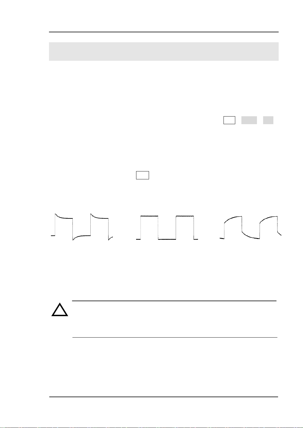
3. Check the shape of the displayed waveform.
Over Compensated Correctly Compensated Under Compensated
Figure 1-9
Figure 1-7 Compensate waveform
4. If necessary, use a non-m etallic tool to adjust the variable ca pacit o r of the probe
for the flattest square wave being displayed on the oscilloscope.
5. Repeat if necessary.
WARNING
!
To avoid electric shock while using the probe, be sure the perfection of the
insulated cable, and do not touch the metallic portions of the probe head
while it is connected with a voltage source.
User’s Guide for DS1000B Series
1-9
Page 28

RIGOL
To Display a Signal Automatically
The oscilloscope has an automated feature to display the input signal in best-fit
status. The input signal should be 50 Hz or higher and a duty cycle is greater than
1%.
Using the automatic setting:
1. Connect a signal to the oscilloscope (such as channel 1) as described above.
2. Press Auto.
The oscilloscope may change the current settings to display the signal; adjusts the
vertical and horizontal scaling, the trigger coupling, t ype, position, level, and mode.
1-10
User’s Guide for DS1000B series
Page 29
RIGOL
To Understand the Vertical System
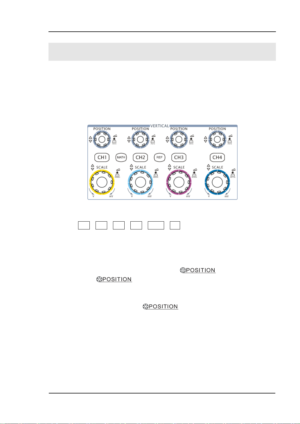
As shown in Figure 1-8, there are several buttons and knobs in the VERTICAL
control area , which are used for setting Channels, MATH and REF functio ns as well as
adjusting vertical position and Volts/div of waveforms. In addition, different colors
are designed for different channels, correspondi ng to differe nt waveforms, so as to
observe clearly.
Figure 1-8 Vertical control
1. Press CH1, CH2, CH3, CH4, MATH, REF, the operating menus, symbols,
waveforms and status information of corresponding channel and settings will be
displayed on the screen. The current selected channel will be shut down when
you press the key associated with the channel one more time.
2. Set vertical position of waveform display by
Turning the
knob, a voltage value is displayed for a short time
knob.
indicating its value with re spect to the gr ound ref erence locate d at the center o f
the screen. Also notice that the ground symbol on the left side of the display
moves in co njunctio n w ith the
knob.
User’s Guide for DS1000B Series
1-11
Page 30
RIGOL
allow you to use greater sensitivity to display the AC component of the
knob to change the vertical display position of
knob to set the vertical display
back to 0 as a sho rtcut ke y, this is especially helpful when the t ra ce
The Coarse/Fine vertical control can be set by simply pressing the vertical
Measurement hints
If the channel is DC coupled, measuring the DC components of the signal by
simply noting its distance from the ground symbol.
If the channel is AC coupled, the DC component of the signal is blocked,
signal.
Vertical offset back to 0 shortcut key
Turn the
channel and press the
position
position is far out of the s creen a nd want it to get back to t he sc reen center
immediately.
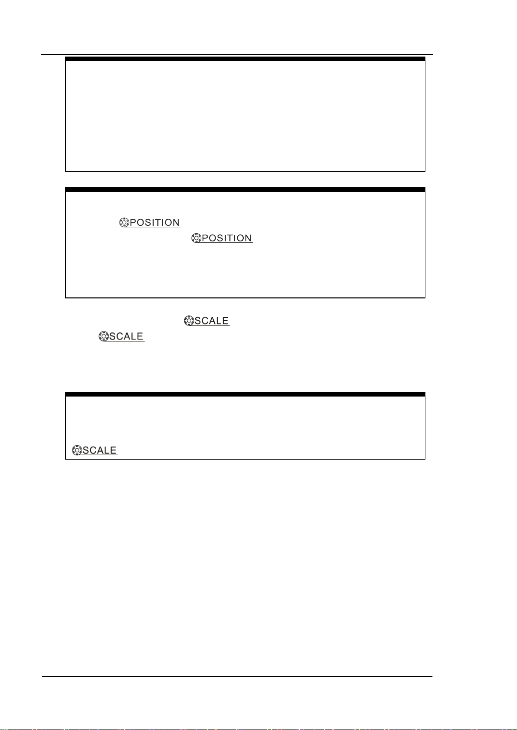
3. Set vertical “Volts/div” by
Rotate
to change “Volts/div”, the change will be displayed in real
knob.
time at the bottom of interface. Besides, the “Volts/div” contains two forms:
“Fine” and “Coarse”.
Coarse/Fine Shortcut key
knob.
1-12
User’s Guide for DS1000B series
Page 31

knob in the horizontal control area on the
panel is another way to enter or exit Delayed Scan mode and it is
To Understand the Hor iz onta l Sy stem
Figure1-9 shows the HORIZONTAL controls: MENU button,
knobs of horizontal system. Following the e x ercise to familiarize with the
buttons, knobs, and status bar.
Figure 1-9 Horizontal control
1. Set horizontal “s/div” by knob.
The horizontal
sequence, and displays the value at t h e upper-left of the display. The time base
ranges of the DS1000B series is from 2 ns /div* to 50 s/div.
knob changes the sweep speed in a 1-2-5 step
RIGOL
and
Delayed Scan Shortcut key
To press the
frontequal to the menu operations, MENU→Delayed→ON.
NOTE*: The speed of horizontal scan varies by different models.
2. Press MENU button to display the “Horizontal” menu. Users can set the delayed
state, time base expansion, time base mo de and trigger of fset.
Term Explanations
Trig-Offset: Denotes the real position of the trigger point relative to the
midpoint of the memory. In this setting, the trig ger position will be chan ged
horizontally when you turning the knob.
User’s Guide for DS1000B Series
1-13
Page 32

RIGOL
3. The horizontal knob moves displayed signal horizontally on the
waveform window.
The horizontal
knob adjusts the trigger offset of signal, when
turning the knob; you can note that the waveform moves horizontally in
conjunction with the knob.
Horizontal offset back to 0 shortcut key
Rotate the horizontal
knob to ad just the horizontal position
of the signal in the waveform window and press it down to restore the
trigger offset or (delayed sweep offset) to the zero point.
1-14
User’s Guide for DS1000B series
Page 33

RIGOL
To Understand the Trigger System
Figure 1-10 shows the TRIGGER control: MODE, MENU, FORCE, 50% and a
knob. Following the exercises to familiarize with the buttons, trigger level
knob and status bar.
Figure 1-10 Trigger control
1. Three kinds of trigger modes can be switched among Auto, Normal and Single
with pressing MODE button.
2. Use the knob to change the settings of trigger level.
Turning the
knob, you will observe an orange trigger line, a trigg er
sign and a trigger level v alue displaying pane on the screen movi ng up and down.
When you stop turning the
knob, the trigger line, trigger sign and
trigger value pane will disappear in five seconds. During the same time of
moving the trigger line, you will notice that the displayed value of trigger level
has been changed on the screen.
Trigger Level back to 0 Shortcut key
Turn the
knob to change the trigger level value and press the
k n ob t o se t t rigger level back to 0 as a shortcut key.
User’s Guide for DS1000B Series
1-15
Page 34

RIGOL
when the
3. Press MENU button in the Trigger control area.
A soft button menu appears on the display showing the trigger setting choices
as shown in Figure 1-11.
Figure 1-11
Press NO.1 menu button to choose Edge.
Press NO.2 menu button to choose Source as CH1.
Press NO.3 menu button to choose Slope as . c.
Press NO.4 menu button to choose Sweep as Auto.
Press NO.5 menu button to enter secondary men u of Set Up.
NOTE: The change of trigger mode, source selection and slope type will lead to
the change of the status bar on the upper-right of the screen.
4. Press FORCE
Start an acquisition even if no valid trigger signal has been found, usually used
in “Normal” or “Single” trigge r mode. This butt on ha s no eff ect if the a cquisitio n
is already stopped.
5. Press 50%
1-16
Switch Local/Remote mode
Press FORCE button to switch the operation mode as “local”
instrument is under remote mode.
Press the 50% button to set the trigger level to the center of the signal’s
amplitude.
User’s Guide for DS1000B series
Page 35

RIGOL
To Understand the Quick Function
The following figure shows that there are two buttons in the QUICK functio n are a.
The exercise below will gradually conduct you to familiarize the settings of the
buttons.
Figure 1-12
The quick function menu
1. Measure
There are two Measure buttons on the front panel, belongin g t o Fun ction Menu
area and Quick Function area respectively. Firstly, you need to pre-set up three
items from 22 measurements via Measure → QuickMea from Function Menu
area, and then press Measure as shown in figure 1-12 to enter quick
measurement, three measuring parameters pre-defined will be displayed on the
screen.
2. Print
Use Print button to perform a quick print or sto re data to USB flash device.
To execute print operation if conne cting t he p rinter s ince it has a higher priority.
To store the measurement results to USB flash device in current format such as
Waveform, Setups, 8 Bitmap, 24 Bitmap, PNG or CSV. Furthermore, it will be
stored as 8-Bitmap automatically when selecting “Factory”.
User’s Guide for DS1000B Series
1-17
Page 36

Page 37

RIGOL
Chapter 2 Operating Your Oscilloscope
By now, a user should understand the VERTICAL, HORIZONTAL and TRIGGER
control syste ms an d kn ow how to determine the system setup from the status bar of
a DS1000B series digital oscilloscope. This chapter will go through all groups of
front-panel buttons, knobs and menus; and further the knowledge of the operation
by hints in this guide. It is strongly recommended to perform all of the following
exercises to get the most of the powerful measurement capabilities of the
oscilloscope.
This chapter covers the following topics:
To Set up the Vertical System
Vertical , Vertical )
(CH1, CH2, CH3, CH4, MATH, REF ,
To Set up the Horizontal System (MENU, Horizontal
Horizontal )
To Set up the Trigger System (MODE,
To Set up the Sampling System (Acquire)
To Set up the Display System (Display)
To Store and Recall (Storage)
To Set up the Utility (Utility)
To Measure Automaticall y (Measure)
To Measure with Cursors (Cursor)
To Use Run Control Buttons (Auto, Run/Stop, Single)
Please read this chapter carefully to get more functions and operations about
DS1000B series oscilloscopes.
, MENU, FORCE, 50%)
,
User’s Guide for DS1000B Series
2-1
Page 38

RIGOL
2-2
blue letters with black
To Set up the Vertical Syste m
Four analog channels are provided by DS1000B: CH1, CH2, CH3 and CH4. Press the
corresponding button on the front panel to turn the channels on/off. The backlight
indicates the channel is currently active. Press the button again to turn the channel
off. When channel is currently selected, press OFF will turn it off and the backlight
goes off.
Table 2-1 Channels menu
Channel
Channel 1
(CH1)
Channel 2
(CH2)
Channel 3
(CH3)
Channel 4
(CH4)
MATH
Other functions such as MATH and REF can be regarded as relatively isolated
channels.
Settings Status Indicator
ON
Selected
OFF
ON
Selected
OFF
ON
Selected
OFF
ON
Selected
OFF
ON
Selected
OFF
CH1 (yellow letters with black background)
CH1 (black letters with yellow background)
No indicator
CH2 (azure
background)
CH2 (black letters with blue background)
No indicator
CH3 (pink letters with black background)
CH3 (black letters with pink background)
No indicator
CH4 (black letter with navy blue background)
CH4 (navy blue letter with black backgr oun d)
No indicator
MATH (purple letter with black background)
MATH (black letter with purple background)
No indicator
User’s Guide for DS1000B series
Page 39

RIGOL
Knobs Explanation
Use the vertical controls to display signal waveforms by adjusting the vertical
knob, and the knob, and setting the input parameters.
1. Using vertical
The vertical
knob.
control changes the vertical position of signal
waveforms in all channels (excluding MATH and REF). The resolution changes
according to the vertical level set. Pressing this knob will clear the channel’s
vertical offse t to ze ro.
2. Using vertical
The vertical
knob.
control changes the vertical sensitivity of signal
waveforms in all channels (excluding MATH and REF). If the Volts/Div is set to
“Coarse”, the waveform scales in a 1-2-5 step sequence from 2
mV ,5mv,10mv… to 10 V. If the Volts/Div is set to “Fine”, it scales to small steps
between the coarse settings. Turn the knob clockwise to decrease the vertical
scale, turn the knob counter-cl ockwis e t o increase the vertical Volts/Div setting.
You can toggle between “coarse” and “Fine” setting through pressing the
knob.
3. During the vertical positioning, a position message is displayed on the left
bottom of the screen, suc h as POS:32.4mv in the same color along with the
corresponding channel. The unit is V (Volts).
User’s Guide for DS1000B Series
2-3
Page 40

RIGOL
2-4
Block DC component of the input
bandwidth to
Set up the probe attenuation factor
Go to the next menu page (The
Channel Settings
Each channel of DS1000B series digital oscilloscope has an independent operation
menu and it will po p-up af t er pre ssi ng a n y but t on a mon g CH1, CH2, CH3, CH4. The
menu to set CH1 is shown in the table below. Press CH1 to enter the following
menus.
Figure 2-1 Table 2-2 Channel menu (Page 1/2)
Menu Settings Comments
AC
Coupling
BW Limit
DC
GND
ON
OFF
Signal.
Pass both AC an d DC compone nts of
the input signal
Disconnect the input signal.
Limit the channel’s
20MHz to reduce display noise.
Get full bandwidth.
0.001X
Probe
Digital Filter Set up digital filter (See table 2-5).
…
1000X
1/2
by 1-2-5 to make the vertical scale
readout correct. including:
0.001X,0.01X,0.1X,1X,2X,5X,10X,20
X,50X,100X,200X,500X,1000X
followings are the same, no more
explanation).
User’s Guide for DS1000B series
Page 41

followings are the same, no more
Figure 2-2 Table 2-3 Channel menu (Page 2/2)
Menu Settings Comments
Back to the previous menu page (The
2/2
explanation).
RIGOL
Define a 1-2-5 sequence.
To change the Volts/Dive settings in
small steps between the coarse settings.
Turn on the invert function.
Restore to original display of the
Volts/Div
Invert
Coarse
Fine
ON
OFF
waveform.
Unit
V/ A/
W/ U
Set “V”, “A”, “W” or “U” as the unit of
vertical channel.
User’s Guide for DS1000B Series
2-5
Page 42

RIGOL
2-6
DC Coupling
DC Coupling
Status Symbol
AC Coupling
AC Coupling
1. To set up channel coupling
To use Channel 1 as an example, input a square wave signal with DC shift.
Press CH1→Coupling→DC to set “DC” cou pling. Both the A C component an d the
DC component of the input signal will pass.
Setup
Figure 2-3 DC coupling settings
Press CH1→Coupling→AC, to set “AC” coupling. It will pass AC component of
the input signal with f reque ncy higher tha n 5 Hz and restraint DC component of
the input signal.
Setup
Status Symbol
Figure 2-4 AC coupling settings
User’s Guide for DS1000B series
Page 43
RIGOL
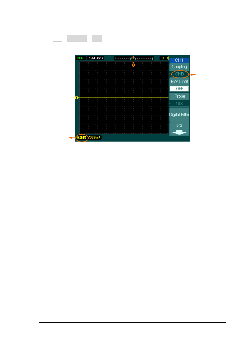
GND
GND Coupling
Status Symbol
Press CH1→Coupling→GND, to set “GND” coupling, it disconnects the input signal.
The screen displays as Figure 2-5:
Coupling
Setup
Figure 2-5 Ground coupling settings
User’s Guide for DS1000B Series
2-7
Page 44
RIGOL
2-8
Mark of
20MHz
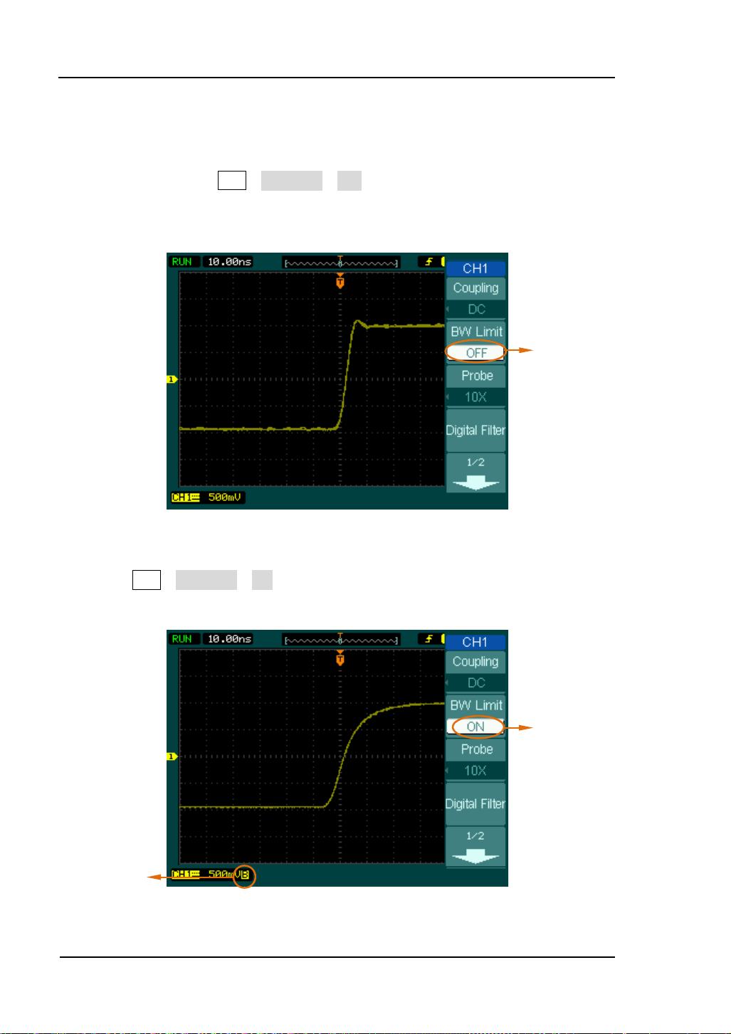
2. To set up the channel bandwidth limit
Take Channel 1 for an example, input a signal containing high frequency
component. Press CH1→BW Limit→OFF, to set up bandwidth limit to “OFF”
status. The oscilloscope is set to full bandwidth and passing the high frequency
component in the signal.
Turn off the
BW Limit
Figure 2-6 Turn off the BW limit
Press CH1→BW Limit→ON, to set up bandwidth limit to “ON” status. It will
restraint the frequency component higher than 20MHz.
BW limit
BW limit
Figure 2-7 Turn on the BW limit
User’s Guide for DS1000B series
Page 45
Probe
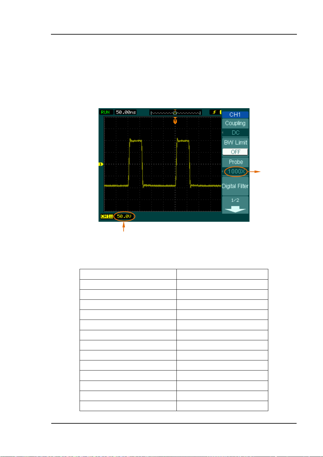
3. To set up Probe Attenuation
The oscilloscope allows selecting the attenuation factor for the probe. The
attenuation factor changes the vertical scaling of the oscilloscope so that the
measurement results refle ct the actual v oltage levels at the probe tip. Figure 2-8
shows an example for using a 1000:1 probe and its attenuation factor.
Attenuation
RIGOL
Vertical volts/div
Figure 2-8 Set up probe attenuation coefficient
Table 2-4 Probe setting
Probe Attenuation Factors Corresponding Settings
1:1000 0.001X
1:100 0.01X
1:10 0.1X
1:1 1X
2:1 2X
5:1 5X
10:1 10X
20:1 20X
50:1 50X
100:1 100X
200:1 200X
500:1 500X
1000:1 1000X
User’s Guide for DS1000B Series
2-9
Page 46
RIGOL
2-10
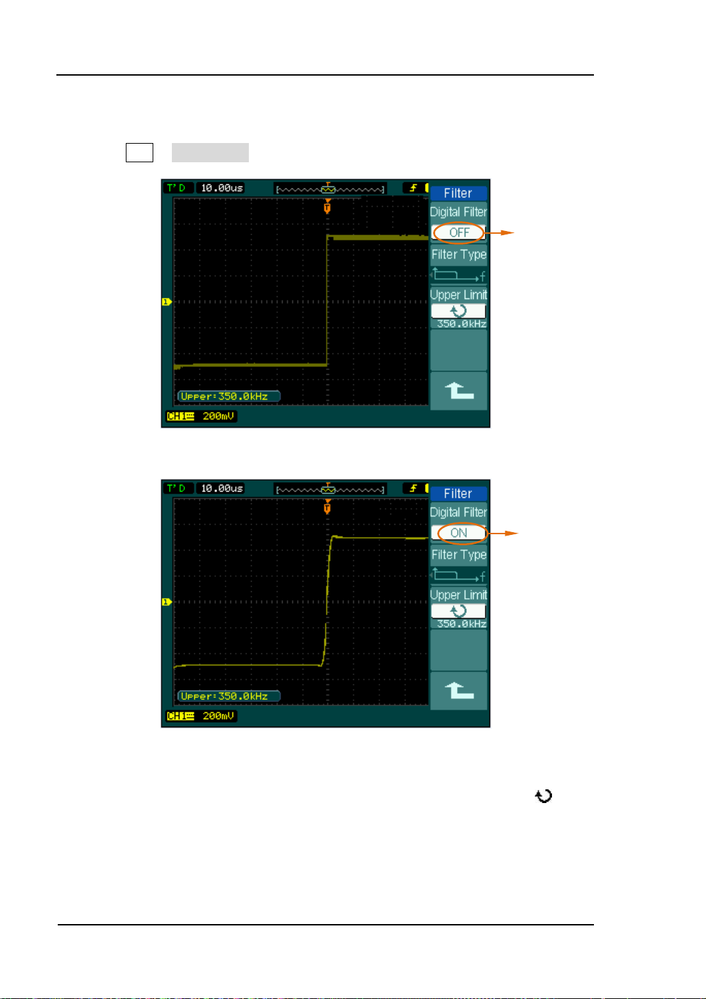
4. Digital Filter
Press CH1→ Digital Filter to display the digital filter menu.
Figure 2-9 Turn off digital filter
Turn Off
Digital Filter
Turn On
Digital Filter
Figure 2-10 Turn on digital filter
Turn the digital filter on or off as shown in the following figure. Turn (
) knob
to adjust the upper and lower limit of frequency aft er turning on the digital filter.
User’s Guide for DS1000B series
Page 47

Figure 2-11 Table 2-5 The Filter menu
Menu Settings Comments
RIGOL
Digital Filter
ON
OFF
Turn on the digital filter.
Turn off the digital filter.
Setup as LPF (Low Pass Filter).
Filter Type
Upper
[1]
Limit
Lower
[1]
Limit
<frequency>
<frequency>
Setup as HPF (High Pass Filter).
Setup as BPF (Band Pass Fi l t e r).
Setup as BRF (Band Reject Filter).
Tu rn (
) knob to set upper limit
high limit.
Turn (
) knob to set lower limit.
Back to higher level menu (The
followings are the same, no more
explanation).
NOTE:
[1] The upper limit needs to be set in the type of low pass filter.
The lower limit needs to be set in the type of high pass filter.
Both upper limit and lower limit need to be set in the types of band pass filter and band reject
filter.
User’s Guide for DS1000B Series
2-11
Page 48

RIGOL
2-12
ge Coarse/Fine setting, not only by menu but also by pressing
Fine
5. To change the Volts/Div settings
The Volts/Div control has Coarse or Fine configuration. The Vertical
Sensitivity is 2mv/div - 10V/div.
Coarse: It is the default setting of Volts/Div in a 1-2-5-step sequence from
2mV/div, 5mV/div, 10mV/div, to 10 V/div.
Fine: This setting changes the vertical scale to small steps between the coarse
settings. It will be helpful to adjust the waveform in smooth steps.
Adjustment
Fine Adjustment Data
Coarse/Fine Shortcut key
To c ha n
vertical knob.
Figure 2-12 Fine Adjustment
User’s Guide for DS1000B series
Page 49

Invert
Invert
6. To invert a waveform
Invert turns the displayed waveform 180 degrees with respect to the ground
level. When the oscilloscope is triggered on the inverted signal, the trigger is
also inverted. Figure 2-13 and Figure 2-14 show the changes before and after
the inversion respectively.
Off
RIGOL
Figure 2-13 Waveform before inversion
On
Figure 2-14 Waveform after inversion
User’s Guide for DS1000B Series
2-13
Page 50

RIGOL
2-14
CH1, CH2,
Define CH1, CH2, CH3 or CH4 as
CH3 or CH4 as
Math Function
The mathematic functions include “add”, “subtract”, “Multiply” an d “FFT ” for CH1,
CH2, CH3 and CH4. The mathematic result can be measured by the grid and the
cursor.
Press MATH button to enter “Math” menu, meanwhile , sign of math scale will a ppear
under the screen. See figure below, waveform of CH1 is marked yellow, waveform of
CH2 is marked blue, and waveform of CH1 adding CH2 is marked purple.
Math Scale
Figure 2-15 Math function
Figure 2-16 Table 2-6 The Math menu (Page 1/2)
Menu Settings Comments
Operate
Source A
Source B
Invert
A+B
A-B
A×B
FFT
CH3, CH4
CH1, CH2,
CH3, CH4
ON
OFF
Add source A and source B.
Subtract source B from source A.
Multiply source B by source A.
Fast Fourier Transform.
source A.
Define CH1, CH2,
source B.
Invert the MATH waveform.
Restore to original waveform display.
User’s Guide for DS1000B series
Page 51

The multifunctional knob ( ) adjusts
Figure 2-17 Table 2-7 The Math m e nu (Page 2/2)
Menu Settings Comments
The multifunctional knob (
the vertical position of the Math
waveform.
RIGOL
) adjusts
Reset
the vertical amplitude of the Math
waveform.
Reset the math waveform to vertical
mid-point.
User’s Guide for DS1000B Series
2-15
Page 52

RIGOL
2-16
1. Using FFT function
The FFT (Fast F ourier Transform) process converts a time -d omain signal into its
frequency components mathematically. FFT waveforms are useful in the
following applications:
Measuring harmonic content and distortion in systems
Characterizing noise in DC power supplies
Analyzing vibration
Press MATH→Operate→FFT to enter FFT setting menu.
Figure 2-18 Table 2-8 The FFT menu (Page 1/2)
Menu
Operate
Source
Settings Comments
A+B
A-B
A×B
FFT
CH1, CH2,
CH3, CH4
Add source A to source B.
Subtract source B from sourc e A.
Multiply source B by source A.
Fast Fourier Transform.
Def ine CH1, CH2, C H3 or CH4 as FFT
source.
Rectangle
Window
Hanning
Hamming
Select window for FFT.
Blackman
Display
Split
Full screen
Display FFT waveform on half screen.
Display FFT waveform on full screen.
Figure 2-19 Table 2-9 The FF T menu (Page 2/2)
Menu Settings comments
Scale
Reset
V
RMS
dBV
RMS
The multifunctional knob (
the vertical position of Math
The multifunctional knob (
the vertical amplitude of Math
Set V
RMS
Set dBV
Reset the math waveform to vertical
mid-point.
as vertical scale unit
as vertical scale unit
RMS
) adjusts
) adjusts
User’s Guide for DS1000B series
Page 53

waveform component magnitude values. To minimize the DC component,
To reduce random noise and aliases components in repetitive or
Key points for FFT
1. Signals that have a DC component or offset can cause incorrect FFT
choose AC Coupling on the source signal.
2.
single-shot events, set the oscilloscope acquisition mode to Average.
3. To display FFT waveforms with a large dynamic range, use the dBV
scale. The dBV
scale displays component magnit udes using a log scale.
RMS
RIGOL
RMS
User’s Guide for DS1000B Series
2-17
Page 54

RIGOL
2-18
the signal
Transients or bursts where the
Single frequency waveforms, to
2. Selecting an FFT Window
DS1000B series oscilloscope provides four FFT windows. Each window is a
trade-off between frequency resolution and amplitude accuracy. It depends on
the desired measurement and the source signals characteristics to determine
the window to use. Use the following guidelines to select the best window.
DS1000B provides four FFT functions with different features, wh ic h ar e ne e ded
to be selected accordi ng to mea s u ring waveform.
Table 2-10 FFT Windows
Window Features Best for measuring
Rectangle
Hanning
Best frequency resolution
and worst amplitude
accuracy.
This is essentially
the same as no window.
Better frequency
resolution, poorer
ampli t ude accurac y than
Transients or bursts,
levels before and after the event
are nearly equal.
Equal-amplitude sine waves with
fixed frequencies.
Broadband random noise with a
relatively slow varying spectrum.
Sine, periodic, and narrow-band
random noise.
Rectangular.
Hamming
Hamming has slightly
better frequency
resolution than Hanning.
signal levels before a nd after the
events are significantly different.
Best ampl itude acc uracy,
Blackman
worst frequency
resolution.
find higher order harmonics.
User’s Guide for DS1000B series
Page 55

This frequency is called the Nyquist frequency. Frequency above the Nyquist
Term Explanations
FFT Resolution: The FFT resolution is the quotient between sampling rate
and the number of FFT points. With a f ixed FFT points, the lower sampling
rate, the better the resolution.
Nyquist Frequency: The highest frequency that any real-time digitizing
oscilloscope can acquire without aliasi ng. It’s no rmally half of the sample rate.
frequency will be under sampled, causing a situation known as aliasing.
RIGOL
User’s Guide for DS1000B Series
2-19
Page 56

RIGOL
2-20
Turn on or turn off one to four REF
REF Function
Reference Wa vefo rms are sa ved wa vefo rms to be selected for display. The reference
function will be av ailable a fter saving the selected w av eform to n on-v olatile m emory.
During the actual measurement process, you can use DS1000B series digital
oscilloscope to observe th e waveforms of correlative components. It will help you to
determine the cause of malfunction when you compare the measured wav eform with
the reference wa vefo rm. T he metho d is pa rticularly u seful under the circumstance of
having reference wav e f or ms.
Press REF button to display the Reference waveform menu.
Figure 2-20 Table 2-11 REF menu when using internal memory (Page 1/3)
Menu Settings Comments
REF 1
Channel
Current
Source
location
REF 2
REF 3
REF 4
REF 1
REF 2
REF 3
REF 4
CH1
CH2
CH3
CH4
MATH
Internal
external
channels
Select the current REF channel which is
optional from REF1 to REF4. (According
to the available channel, for example, if
only REF1 is turned on, then only REF1
can be chosen as the current channel.)
Select CH1, CH2, CH3, CH4, an d MATH as
the source channel whose input
waveforms will be compared with the
refere nce wavefo rms.
Select memory location in scope.
Select memory location out scope.
User’s Guide for DS1000B series
Page 57

RIGOL
Figure 2-21 Table 2-12 REF menu when using inte rnal/exte rnal mem ory (Page 2/3)
Menu Settings Comments
Save
Save REF waveform to outer me mory
location.
The multifunctional knob (
the vertical position of REF
) adjusts
Figure 2-22 Table 2-13 REF menu when using internal memory (Page 3/3)
Menu settings comments
Reset
Imp./Exp.
The multifunctional knob (
the vertical amp litude of REF
Reset REF waveform.
Go to import menu (s e e table 2-19).
) adjusts
Figure 2-23 Table 2-14 REF menu when using external memory (Page 3/3)
Menu settings comments
Reset Reset REF waveform.
Import Go to import menu (s e e table 2-19).
User’s Guide for DS1000B Series
2-21
Page 58

RIGOL
2-22
1. Import and Export
Switch to external memory and select Internal location.
Then, press REF →Imp. /Exp. and enter the following interface.
Figure 2-24 Import and export interface
Figure 2-25 Table 2-15 Imp. /Exp. Menu
Menu Settings Comments
Path
Explorer
Directory
Switch to Path, directory or file.
File
Export the REF file from internal
Export
memory to ext er n al memory (see
table 2-16).
Import
Import the REF file to internal
memory.
Delete File Delete file.
User’s Guide for DS1000B series
Page 59

2. Export
Switch to external memory and select Internal location.
Then, press REF→Imp. /Exp.→ Export and go to the following interface.
Figure 2-26 Export interface
Figure 2-27 Table 2-16 The Export menu
RIGOL
Menu Settings Comments
Save Execute the operation.
User’s Guide for DS1000B Series
Move the input focus point of files’ name
up and down.
Move the focus point to next location.
To delete chosen letter.
2-23
Page 60
RIGOL
2-24
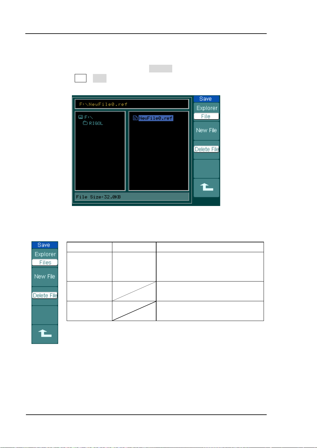
3. Save to External Memory
Switch to external memory and select External location.
Then, press REF→Save and enter the following interface.
Figure 2-28 Save in t erface
Figure 2-29 Table 2-17 The Save menu
Menu Settings Comments
Explorer
New File
(Folder)
Delete File
(Folder)
Path
Directories
Files
Delete chosen file (Folder).
Switch among Path, Direct ories and
Files.
Set up new file in Path and File. Set
up new folder in directory.
User’s Guide for DS1000B series
Page 61

RIGOL
Move the focus point to the next
File Name
Switch Chinese
Switch Capital
4. New File (or New Folder)
Switch to external memory and select External location.
Then, press REF→Save→New File (or New Folder) and go to the following
interface.
Input Pane
and English
On or Off
Figure 2-30
File name in English inputting interface
Figure 2-31 Table 2-18 The New File menu
Menu Settings Comments
Save Execute the saving operat ion.
User’s Guide for DS1000B Series
To delete chosen letter.
Move the focus p oint of file name up
and down.
location.
2-25
Page 62

RIGOL
2-26
5. Import
Switch to external memory and select External location.
Then, press REF→Import and enter the following interface.
Figure 2-32 Import interface
Figure 2-33 Table 2-19 The Import menu
Menu Settings Comments
Explorer
Import
Path
Directories
Files
Switch among Path, Directories and
Files.
Import the REF file into internal
memory.
User’s Guide for DS1000B series
Page 63

RIGOL
6. Display a Re ference Waveform
Figure 2-34
Reference waveform display
Operation introductions:
1. Press REF button to show the reference waveform menu.
2. Press soft button 3 to select the reference channel: CH1, CH2, CH3, CH4 or
MATH.
3. Turn vertical and vertical to adjust the REF
waveform to a suitable position.
4. Press soft button No.4 to select the s ave loc a t i on of REF waveform.
5. Enter to REF menu (Page2/3) Press soft button No.2 to save the waveform as
REF.
NOTE: The Reference function is not available in X-Y mode.
User’s Guide for DS1000B Series
2-27
Page 64

RIGOL
2-28
horizontally around the center of the
screen when the horizontal time base
ontally around the trigger point
when the horizontal time base is
elation between
Show CH1 amplitude value at X axis;
In Roll Mode, the waveform display
Adjust the trigger position to the
To Set up the Horizontal System
Press MENU button to enter the horizontal setting system.
Figure 2-35 Table 2-20 The Horizontal menu
Menu Settings Comments
Delayed
ON
OFF
ScreenCenter
TimeExpand
NOTE:
[1] In Roll mode, bo th the horizontal
Once the oscilloscope is set to Roll mode, the time base should be 50ms or slower.
Time Base
Trig-Offset Reset
Trigger
User
Y-T
X-Y
Roll
[1]
Turn on the Delayed Scan mode.
Tu r n off the Delayed Scan mode.
The waveform expands or compresses
is changed.
The waveform expands or compresses
horiz
changed.
The waveform expands or compresses
horizontally around the user-defined
reference position when the horizontal
time base is changed.
Show the relative r
vertical voltage and horizontal time.
show CH2 amplitude value at Y axis.
updates from right to left.
center of the memory.
knob and tri gger control are inoperative.
User’s Guide for DS1000B series
Page 65

Term Explanations
to 50ms or slower. In this mode, the oscilloscope acq uires sufficient data for the
left part to the trigger point, then wait for trigger, when trigger occurs, it
When choosing this mode to view low frequency signals, it is recommended
Slow Scan Mode: This mode is available whe n th e horiz ontal time base is s et
continue to draw the rest part from the trigger point t o the end of the right si de.
that the channel coupling be set as DC.
RIGOL
User’s Guide for DS1000B Series
2-29
Page 66

RIGOL
2-30
Knobs Explanation
The horizontal controls change the horizontal scale and position of waveforms. The
horizontal center of the screen is the time reference for waveforms. Changing the
horizontal scale causes the waveform to be expanded or comp ressed with respect t o
the screen center. Horizontal position changes the displayed waveform position,
relative to the trigger point.
1. The horizontal
knob adjusts the horizontal position of all
channels (including Math) waveforms. The resolution of this control varies with
the time base. Pressing this button clears the trigger offset and moves the
trigger point to the horizontal center of the screen.
2. Use
to select the horizontal time/div (scale factor) for the main or
the Delayed scan time base. When Delayed Scan is enabled, it changes the
width of the window zone by changing the Delayed Scan time base.
User’s Guide for DS1000B series
Page 67
RIGOL
Time Base of
Delayed Scan
Time Base of
Delayed Scan
Delayed Scan
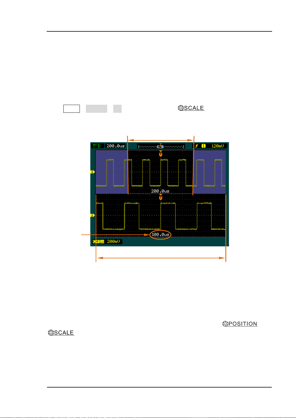
The Delayed Scan is a ma gnified portion of the main w aveform window . Use Delayed
Scan to locate and h orizonta lly expand part of t he main wave form wi ndow f or a mor e
detailed (higher horizontal resolution) a nalysis of signal. The Delayed Scan time base
setting cannot be set slower than the Main time base setting.
Press MENU→Delayed→ON, or press horizontal knob to turn on delayed
scan function. See the waveform below.
Waveform to be Horizontally Expanded
Waveform to be Horizontally Expanded
Expanded Waveform in Horizontal
Figure 2-36 Delayed scan windows
The screen will be split into two parts.
The upper half displays the main waveform window and the lower half displays an
expanded portion of the main wa v efo rm wind ow. This expanded portion of th e main
window is called the Delay ed Scan window . Two blocks shaded at the upper ha lf; the
un-shaded portion is expanded in the lower half. The horizontal
and
knobs control the size and position of the Dela ye d Scan. T he v alue at t op
of the screen is the main time base and the value on the center bottom means the
Delayed Scan time base.
User’s Guide for DS1000B Series
2-31
Page 68

RIGOL
2-32
X-Y Format
This format is useful for studying phase relationships between CH1 and ch 2 (CH3
and CH4 can’t be used).CH1 in the horizontal a xis(X) a nd CH2 in the ve rtical a xis(Y ),
the oscilloscope uses a none-trigger acquisition mode, data is di splayed as d ots.
Press MENU→Time Base→X-Y to enter X-Y mode.
Figure 2-37 X-Y display format
The oscilloscope can acquire waveforms with any sampling rate in Y-T mode (u p to
2GSa/s for single channel or half channel
[1]
). But in X-Y mode, up to 1GSa/s can be
used and the default is 250MSa /s. Generally, the lower the sample rate is, the better
the Lissajous graphic will be.
NOTE [1]: Half channel in dicates selecti ng one o f the c hann els in CH1 and CH 2, or in CH 3 and
CH4.
The following modes or functions will not work in X-Y format.
Cursor measurement (Track and Auto modes)
Pass/Fail Function
REF and MATH Operations
Delayed Scan Mode
Vector Display Mode
Horizontal
knob
Trigger Controls
User’s Guide for DS1000B series
Page 69

RIGOL
To Set up the Trigger System
The trigger determines when the oscilloscope starts to acquire data and display a
waveform. When a trigger is set up properly, it can convert unstable displays or blank
screens into meaningful waveforms.
When the oscilloscope starts to acquire a wav eform, it collects enou gh data so that it
can draw the waveform to the left of the trigger point. The oscilloscope continues to
acquire data while wait ing for the trigger condition to occur. After it det ects a t rigger,
the oscilloscope continues to acquire enough data so that it can draw the waveform
to the right of the trigger point.
Press MENU button to enter trigger system setting inter fac e.
Figure 2-38 Trigger system interface
DS1000B provides five trigger modes: Edge, Pulse, Vide o, Pattern and Alternative .
Edge: An edge trigger occurs when the trigger input passes through a specified
voltage level in the specified slope direction.
Pulse: Use this trigger mode to catch pulses with certain pulse width.
Video: Use video trigger mode on fields or lines for standard video signals.
Pattern: Recognising trigger by searching specified code.
Alternative: Trigger on non-synchronized signals.
User’s Guide for DS1000B Series
2-33
Page 70
RIGOL
2-34
Edge Trigger
An edge trigger determines whether the oscilloscope find s the trigger point on the
rising or the falling edge of a signal. Select Edge trigger Mode to trigger on Rising
edge, falling edge or rising & falling edge.
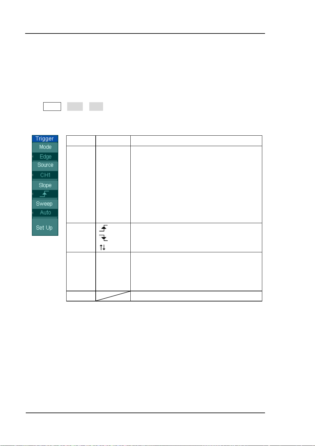
Press MENU→Mode→Edge to enter the following menu.
Figure 2-39 Table 2-21 The Tr igger menu
Menu Settings Comments
Source CH1
CH2
CH3
CH4
EXT
EXT/5
AC Line
Slope
Sweep Auto
Set up To go to Se t Up menu , see table 2-34
Normal
Single
Select CH1 as trigger source.
Select CH2 as trigger source.
Select CH3 as trigger source.
Select CH4 as trigger source.
Select EXT TRIG as trigger source.
Select attenuated EXT TRIG/5 as trigger
source.
Select power line as trigger source.
Trigger on rising edge.
Trigger on falling edge.
Trigger on both ring & falling edge.
Acquire waveform even no trigger occurred.
Acquire waveform when trigger occurred.
When trigger occur s, acquir e o ne wave fo rm
then stop.
User’s Guide for DS1000B series
Page 71

RIGOL
EXT TRIG/5 as trigger
Set Pulse width as
Set Pulse width as
Set Pulse width as
Set Pulse width as
Set
Set Pulse width as
Pulse Width Trigger
Pulse trigger occurs according to the width of pulse. The abnormal signals can be
detected through setting up the pulse width condition. Press MENU→Mode→Pulse to
enter the following menu.
Figure 2-40 Table 2-22 The Trigger menu (Page 1/2)
Menu
Source
Settings Comments
CH1
CH2
CH3
CH4
EXT
EXT/5
Select CH1 as trigger source.
Select CH2 as trigger source.
Select CH3 as trigger source
Select CH4 as trigger source l
Select EXT TRIG as trigger source
Select attenuated
source.
When
Settings
<Width>
Pulse width as “-pulse width more than”
To set required pulse width.
Figure 2-41 Table 2-23 The Trigger menu (Page 2/2)
“+pulse width less than”
“+pulse width more than”
“+pulse width equal to”
“-pulse width less than”
“-pulse width equal to”
Menu Settings Comments
Auto
Sweep
Normal
Single
Set Up
NOTE: The Pulse width adjust range is 20ns~10s. When the condition
is met, it will trigger and acquire the waveform.
User’s Guide for DS1000B Series
Acquire waveform even no trigger occurred.
Acquire waveform when trigger occurred.
When trigger occurs, acquire one waveform
and then stop.
To go to Se t Up menu, see table 2-34.
2-35
Page 72

RIGOL
2-36
Video Trigger
Choose video trigger to trigger on fields or lines of NTSC, PAL, or SECAM standard
video signals. Trigger coupling preset to DC. Press MENU→Mode→Video to enter the
following menu.
Figure 2-42 Table 2-24 The Video Trigger menu (Page 1/2)
Menu Settings Comments
Selects CH1 as trigger source.
Selects CH2 as trigger source.
Selects CH3 as trigger source.
Selects CH4 as trigger source.
Select EXT TRIG as trigger source.
Select EXT TRIG/5 as trigger source.
Source
CH1
CH2
CH3
CH4
EXT
EXT/5
Normal
Polarity
[1]
polarity
Inverted
polarity
All Lines
Sync
Line Num
Odd field
Even fiel d
Note:
[1] Normal polarity is applicable to signal with negative horizontal sync pulse; Inverted
polarity is applicable to signal with positive horizontal sync pulse.
Trigger on the negative edge of the sync
pulse
Trigger on the positive edge of the sync
pulse
Trigger on all lines.
Trigger on a specified line.
Select to trigger on odd field.
Select to trigger on even field.
User’s Guide for DS1000B series
Page 73

Figure 2-43 Table 2-25 The Video Trigger menu (Line Num, Page 2/2)
RIGOL
Menu
Settings Comments
The range is from No.1 to No.525 when
Line Num
< Line sync >
NTSC video standard i s used and from
No.1 to No.625 when PAL/SECAM video
standard is used.
Standard
Sweep
PAL/SECM
NTSC
Auto
Normal
Single
Select Video sta ndard.
Acquire waveform even no trigger
occurred.
Acquire waveform when trigger
occurred.
When trigger occurs, acquire one
waveform and then stop.
Se t Up To go to set up menu, see Table 2-36.
Figure 2-44 Table 2-26 The Video Trigger menu (All lines, Od d field and Even field,
Page2/2)
Menu Settings Comments
Standard
Sweep
PAL/SECAM
NTSC
Auto
Normal
Single
Select Video standard.
Acquire waveform even no trigger
occurred.
Acquire waveform when trigger
occurred.
When trigger occurs, acquire one
waveform and then stop.
Se t Up To go to set up menu, see Table 2 -36.
User’s Guide for DS1000B Series
2-37
Page 74

RIGOL
2-38
Select “Line Synchronization”: Select “Filed Synchronization”:
Figure 2-45 Figure 2-46
Video Trigger: Line Synchronization Video Trigger: Field Synchronization
User’s Guide for DS1000B series
Page 75

RIGOL
Menu
To set EXT/5 as trigger source to expand
Auto
Acquire waveform even no trigger
When trigger occurs, acquire one
Pattern Trigger
Pattern trigger recognises the trigger condition through inspecting the code preset
which means the logic values or the logic combination.Every channel has its own
logic value,such as,logic high value,logic low value,and the neglect value. Press
MENU→Mode→Pattern to enter the following menu.
Figure 2-47 Table 2-27 The Pattern Trigger menu
Settings Comments
Channel
Code
CH1
CH2
CH3
CH4
EXT
EXT/5
H
L
X
To select CH1 as trigger source
To select CH2 as trigger source
To select CH3 as trigger source
To select CH4 as trigger source
To set EXT as trigger source
trigger level range.
To set the code of the selected channel as
logic high value.
To set the code of the selected channel as
logic low value.
To set the code of the selected channel as
neglect value.
To speci fy trigger to the rising edge of
signal
To spec i fy trigger to the falling edge of
signal
Sweep
Normal
Single
Set up To go to set up menu, see Table 2-34.
User’s Guide for DS1000B Series
occurred.
Acquire waveform when trigger occurred.
waveform then stop.
2-39
Page 76
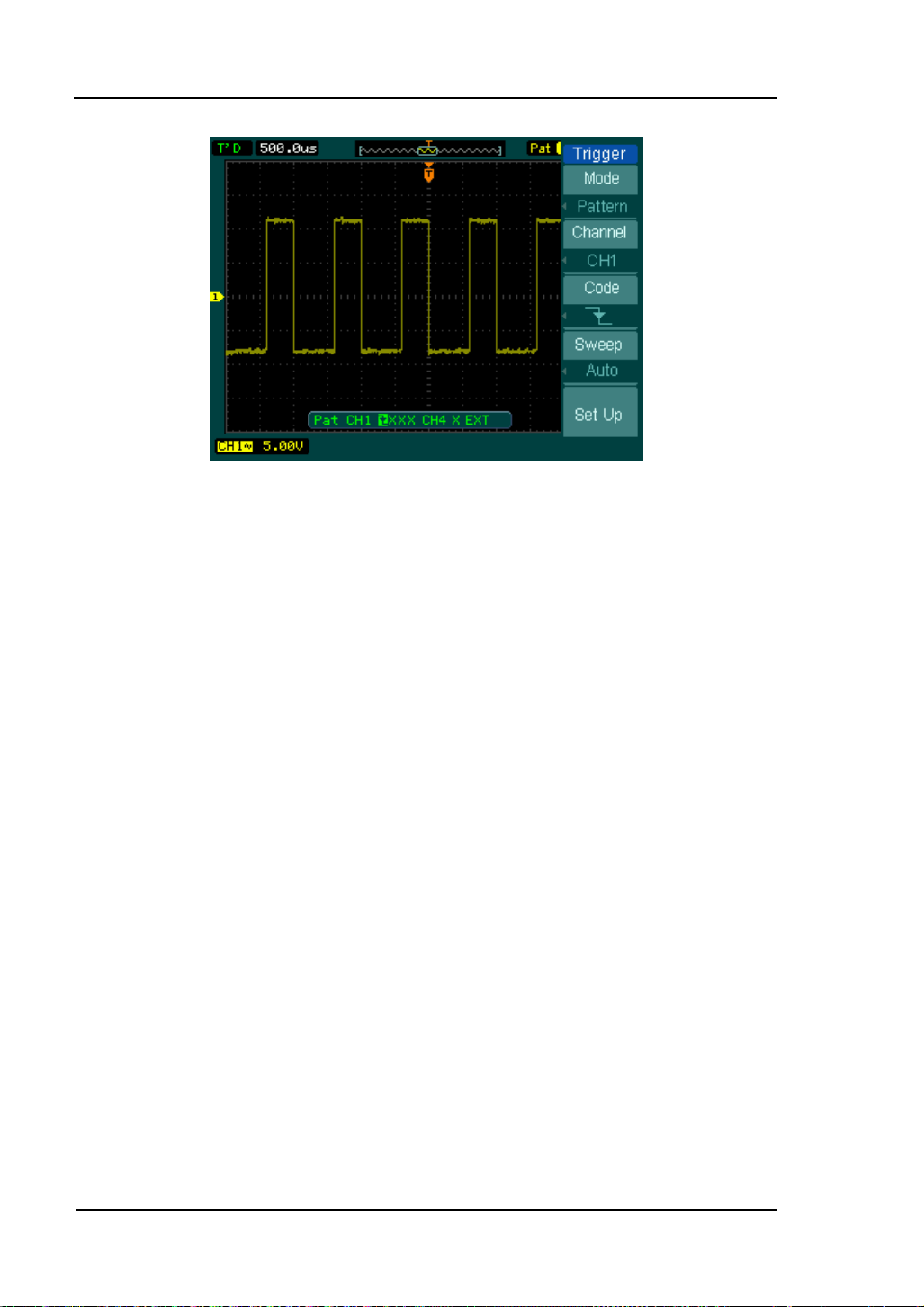
RIGOL
2-40
Figure 2-48
Pattern trigger: set code as falling edge
User’s Guide for DS1000B series
Page 77

RIGOL
To specify the current alternative trigger
channels as any two channels selected
Choose trigger type for the current
Alternative Trigger
When alternative trigger is on, the trigger sources come from two vertical channels.
This mode can be used to observe two non-related signals. You can choose two
different trigger modes for the two vertical channels. The options are as follows:
Edge, Pulse and video. The info of the trigger level of the two channels will be
displaye d on the u pper-right of the screen. Press MENU→Mode→Alternative to enter
the following menu.
Figure 2-49 Table 2-28 The Alternative trigger menu (Page 1 /2 Trigger T ype : Edge )
Menu Settings Comments
CH1-CH2
CH1-CH3
Alt Channel
select
Type
CH1-CH4
CH2-CH3
CH2-CH4
CH3-CH4
CH1, CH2
CH3, CH4
Edge
Pulse
Video
form CH1, CH2, CH3, CH4.
To select vertical channel among CH1,
CH2, CH3, CH4 in alternative trigger
mode so as to configure further settings.
channel.
Figure 2-50 Table 2-29 The Alternative trigger menu (Page 2/2 Trigger Type: Edge)
Menu settings comments
Edge type
Set up
User’s Guide for DS1000B Series
Trigger on rising edge.
Trigger on falling edge.
To go to s e t up me n u. See Table 2 -34
2-41
Page 78

RIGOL
2-42
To specify the current alternative
mode so as to configure further
Video trigger
Select trigger type for current
Set Pulse width as
than”
Set Pulse width as
tha
Set Pulse width as
to”
Set Pu
ulse width less
than”
Set
than”
Set Pulse width as
to
Figure 2-51 Table 2-30 T he Alternative trigger menu (Page 1 /2 Trigger T ype: Pulse)
Menu Settings Comments
CH1-CH2
CH1-CH3
Alt Channel
CH1-CH4
CH2-CH3
CH2-CH4
trigger channels as any two channels
selected form CH1, CH2, CH3, CH4.
CH3-CH4
T o sele ct vertical channel among CH1,
select
CH1, CH2,
CH3, CH4
CH2, CH3, CH4 in alternative trigger
settings.
Edge trigger
type
Pulse trigger
channel.
Figure 2-52 Table 2-31 T he Alternative trigger menu (Page 2 /2 Trigger T ype: Pulse)
Menu Settings Comments
When
Settings
Set Up
<Pulse width >
“+pulse width less
“+pulse width more
n”
“+pulse width equal
lse width as “-p
Pulse width as “-pulse width more
“-pulse width equal
”
To set up width value of the pulse.
T o go to set up menu. See Table 2-34.
User’s Guide for DS1000B series
Page 79

RIGOL
Select to trigger on even
Figure 2-53 Table 2-32 T he Alternative trigger menu (Page 1/2 Trigger Type: Video)
Menu Settings Comments
To specify the current
alternative trigger channels
as any two channels selected
form CH1, CH2, CH3, CH4.
Alt Channel
CH1-CH2
CH1-CH3
CH1-CH4
CH2-CH3
CH2-CH4
CH3-CH4
To select vertical channel
among CH1, CH2, CH3, CH4
in alternative trigger mode
select
CH1, CH2,
CH3, CH4
so as to configure further
settings.
Type
Edge trigger
Pulse trigger
Video trigger
To select trigger type for
current channel.
Figure 2-54 Table 2-33 The Alternative trigger menu (Page 2/2 Trigger Mode: Vide o)
Menu Settings Comments
Trigger on the negative edge
Polarity
[1]
Normal polarity
Inverted polarity
of the sync pulse
Trigger on the positive edge
of the sync pulse
ALL lines
Sync
Line Num
Odd field
Even fiel d
Standard
PAL/SECM
NTSC
Set Up
Note:
[1] Normal polarity is applicable to signal with negative horizontal sync pulse; Inverted polar ity is
applicable to signal with positive horizontal sync pulse.
Trigger on all lines.
Trigger on a specified line.
Select to trigger on odd field.
field.
Select Video sta ndard.
To go to set up menu, see
Table 2-36.
User’s Guide for DS1000B Series
2-43
Page 80

RIGOL
2-44
ot before another
between 100ns
Trigger Settings
Set up different trigger settings according to different trigger modes. In Edge, Pulse
and Pattern trigger modes. You need to set up coupling, sensitivity and trigger
holdoff; in video trigger mode, to set up sensitivity and holdoff; in alternate trigger,
different trigger types have different setting options.
Figure 2-55 Table 2-34 The Trigger Set Up menu
(Page 1/2 Settings for Edge, Pulse and Pattern Triggers)
Menu Settings Comments
Allow all signals pass.
Block DC signals.
Reject DC and low frequency
signals.
Passes high frequency
component.
Blocks high frequency
component, passes low
frequency component.
Set trigger sensitivity between
0.1div to 1.00div.
Set time sl
trigger event
to 1.5s.
Coupling
HF reject
Sensitivity
Holdoff
DC
AC
LF Reject
ON
oFF
<Sensitivity Setting>
<Holdoff Setting>
User’s Guide for DS1000B series
Page 81

RIGOL
Set time slot before another
Figure 2-56 Table 2-35 Page 2/2 S ettings for Edge, Pulse and Pattern Triggers
Menu Settings comments
Holdoff
Reset Reset Holdoff tim e to 500ns.
Figure 2-57 Table 2-36 Settings for Video Trigger
Menu Settings Comments
Sensitivity
Holdoff
<Sensitivity Setting>
<Holdoff Setting>
Set trigger sensitivity between
0.1div to 1.00div.
trigger event between 100ns to
1.5s.
Holdoff Reset Reset Holdoff time to 500ns.
User’s Guide for DS1000B Series
2-45
Page 82

RIGOL
2-46
Trigger
Trigger Holdoff
You can use trigger Holdoff to stabilize a complex waveform, such as a pulse
sequence. Holdoff time is the oscilloscope’s waiting period before starting a new
trigger. During Holdoff, oscilloscope will not trigger until Holdoff ends. For instance:
To trigger on the first pulse on a group of them, users can set the holdof f time to
Pulse cluster width.
Position
Trigger Holdoff
Time of Holdoff
Figure 2-58 Trigger holdoff
Operation Explanations:
1. Press the MENU button of the trigge r control syste m to display the Menu.
2. Press Set Up key to display trigger set up menu.
3. Turn the multi function knob ( ) to change Holdoff time until waveform is
stable.
4. Press Trigger Holdoff→Reset to reset the Holdoff time to its default value
(500ns).
User’s Guide for DS1000B series
Page 83

Trigger Terms Explanation
1. Trigger Source:
Trigger occurs from several sources: Input channels (CH1, CH2, CH3, CH4), AC
Line, Ext, Ext/5.
CH1, CH2, CH3, CH4:
It is the most commonly used trigger source. The channel works when it is
selected as a trigger source whatever displayed.
Ext Trig:
The instrument can be triggered from an external source while acquiring data
from CH1, CH2, CH3, and CH4. For example, be a trigger source with an
external clock or a signal from another part of the test circuit. The Ext, Ext/5
trigger sources use an external trigger signal connected to the EXT TRIG
connector. Ext uses the signal directly; it has a trigger level range of -0.6 V to
+0.6 V. The EXT/5 trigger source attenuates the signal by 5X, which e xtends the
trigger level range to -3V to +3 V allowing the oscilloscope to trigger on a larger
signal.
AC Line:
AC power can be used to display signals related to the power line frequency,
such as lighting equipment and power supply devices. The oscilloscope gets
triggered on its AC power input, but an AC trigger signal is not required.
2. Trigger Mode:
The trigger mode determines how the oscilloscope behaves in the absence of a
trigger event. The oscilloscope provides three trigger modes: Auto, Normal, and
Single.
Auto:
This sweep mode allows the oscilloscope to acquire waveforms even when it
does not detect a trigger condition. If no trigger condition occurs while the
oscilloscope is waiting for a specific period (as determined by the time-base
setting), it will force itself to trigger.
When forcing inv alid triggers, the oscillos cope cannot synchroni ze the wav eform ,
and the waveform seems to roll across the display. If valid triggers occur, the
RIGOL
User’s Guide for DS1000B Series
2-47
Page 84

RIGOL
2-48
display becomes stable on the screen.
Any factor results in the inst ability of wa veforms can be detected by Auto T rigger,
such as the output of Power supply.
NOTE: When horizontal control is set under 50 ms/div, Auto mode allows the
oscilloscope not to capture trigger signal.
Normal:
The Normal mode allows the oscilloscope t o acquire a wavef orm only when it is
triggered. If no trigger occurs, the oscilloscope keeps waiting, and the previous
waveform will remain on the display.
Single:
In Single mode, after pressing the Single key, the oscilloscope waits for trigger.
While the trigger occurs, the oscilloscope acquires one waveform then stop.
3. Coupling:
Trigger coupling determines which signal component passing to the trigger
circuit. Coupling types include AC, DC, LF Reject and HF Reject.
AC: AC coupling blocks DC components and attenuate signal lower than 10 Hz.
DC: DC coupling pas ses both AC an d DC components.
LF Reject: LF Reject coupling blocks DC component, and attenuate s all signal
with a frequency lower than 10 kHz.
HF Reject: HF Reject coupling attenuates all signals with a frequency higher
than 100 kHz.
4. Pre-trigger/delayed trigger:
The data is collected before and after trigger.
The trigger position is typically set at the horizontal center of the screen. In the
full-screen display the 6div data of pre-trigger and delayed trigger can be
surveyed. More data (14div) of pre-trigger and 1s delayed trigger can be
surveyed by adjusting the horizontal
knob.
This feature is very useful to study the events that led up to the trigger po int.
Everything on the right of the trigger point is called post-trigger information.
Delay range (pre-trigger and post-trigger information) depends on the sweep
speed selected.
User’s Guide for DS1000B series
Page 85

5. Adjustable trigger sensitivity
T o a void the infl uence of noise from the physical w orld, and get t he stable trigg er,
the trigger circuit has adopted Stickiness. In DS1000 B seri es, the stickiness is
adjustable from 0.1div-1.0div, which means when it sets to 1.0div; the trigger
circuit will not aff ect any si gnal wit h peak-peak amplitude less than 1.0div, so as
to avoid the influence of the noise.
RIGOL
User’s Guide for DS1000B Series
2-49
Page 86

RIGOL
2-50
To Set up the Sampling Syste m
Figure 2-59
Press Acquire button, the interface menu shows as follows:
Figure 2-60 Table 2-37 The Acquire menu
shows, the Acquire button at the MENU of the front panel.
Acquire Setup Button
Figure 2-59
The Acquire setup button
Menu Settings Comments
Normal
Acquisition
Average
Peak Detect
Averages
Sampling
Sinx/x
Sa Rate
NOTES:
[1] This function appears when acquisition as “Average”.
[2] This function appears when sampling as “Real-Time”.
[3] Sample rate channels will be displayed respectively in alternative trigger mode.
[1]
2 to 256
Real-Time
Equ-Time
[2]
[3]
ON
OFF
Display sampling rate.
Normal Acquisition mode.
Average Acquisition mode .
Peak Detect Acquisition mode.
Set average times by N-th power
of 2 from 2 to 256.
Real-time sampling mode.
Equivalent sampling mode.
Set the interpolation as Sinx/x.
Set the interpolation as linearity.
User’s Guide for DS1000B series
Page 87

RIGOL
The waveform dis played on the screen will change in conjunction w ith t he setting of
Acquire menu.
To reduce the displayed random noise, select the Average Acquisition. This
mode would make the screen refresh slower.
To Avoid signal aliasing, select Peak Detect Acquisition.
Select Real-time acquisition to observe the single-shot or pulse signals.
Select Equ-Time to observe high frequency repetitiv e signal s.
Figure 2-61
Signal that contains noise, and without average sampling
Figure 2-62
Displ ay signal after average sampling
User’s Guide for DS1000B Series
2-51
Page 88

RIGOL
2-52
When the scope is acquiring waveforms, the
will be displayed, the position and scale can still be adjusted by vertical
Figure 2-63
Adopt Normal acquisition
Figure 2-64
Adopt peak detect acquisition, signal contains envelope
Key points
Stop Acquisition:
waveforms is in a liv e st atus; when acquisition is stopped, frozen waveform
control and horizontal c ontrol.
User’s Guide for DS1000B series
Page 89

or faster, the oscilloscopes use the sine(x)/x interpolation to expand the
Known as Repetitive sampling to get up to 20ps of horizontal resolution
(equivalent 50Gsa/s). This mode is good for observing repetitive signals,
Apply averaging to your signal to remove uncorrelated noise and improve
display. The averaged waveform is a running average over a specified
Key Points:
Real-time Sampling:
DS1000B has Real-time sampling rate up to 2GSa/s. At the time base 20ns
horizontal time base.
Equivalent sampling:
and it is not recommended for single-shot or pulse.
Normal Acquisition:
Oscilloscope acquires signal by equal time interval.
Average Acquisition:
measurement accuracy. Reduces ran d om or un corre lated n oise i n the si gnal
RIGOL
number of acquisitions from 2 to 256.
Peak Detect:
Peak Detect mode captures the maximum and minimum values of a signal,
and finds highest and lowest record points over man y acquis it ions.
User’s Guide for DS1000B Series
2-53
Page 90

RIGOL
2-54
(0% to
To Set up the Display Sys tem
The menu button for the display system on the f r on t panel is shown in the following
figure.
Figure 2-65 The display setup button
Press the Display button, the interface menu for settings shows as follows.
Figure 2-66 Table 2-38 The Display menu (Pag e 1 /3)
Display Setup Button
Menu Setting Comments
Type
Clear
Persist
Intensity
Vectors
Dots
Infinite
OFF
<
waveform
intensity
>
Display waveforms as vec to rs.
Display waveforms as dots.
Clear all existing waveforms from
screen.
The sample points remain displayed
until turn the persistence “OFF”.
Tu r n off the persistence function.
Set up waveform intensity
100%).
User’s Guide for DS1000B series
Page 91
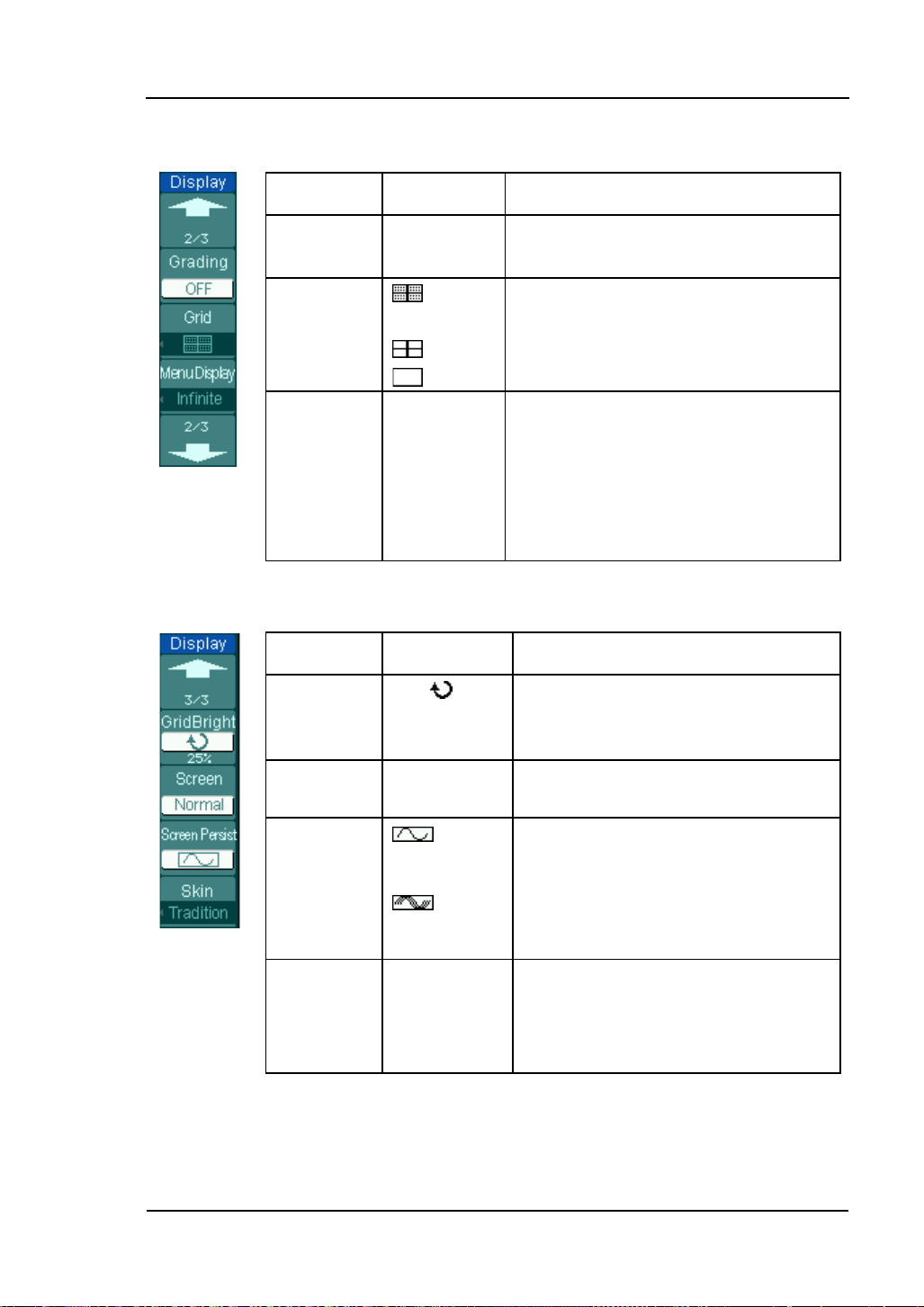
Display grids and coordinates on the
(0% to
To show the last acquired waveform
To show the accumulated acquired
waveforms when the acquisition is
Figure 2-67 Table 2-39 The Display menu (Page 2/3)
Menu Settings Comments
RIGOL
Grading
Grid
ON
OFF
The waveform is displayed in multiple
levels of pixel intensity.
screen.
Turn off the grids.
Turn off the grids and coordinates.
1s
Menu
Display
2s
5s
10s
20s
Set the time before menu fades away.
The menu will be hidden after the set
time of last button pressing.
Infinite
Figure 2-68 Table 2-40 The Display menu (Page 3/3)
Menu
GridBright
Screen
Settings Comments
<
grid
brightness
Normal
Inverted
>
Set up grid brightness
100%).
Set to normal mode.
Set to invert color display mode.
Screen
persist
when the acquisition is stopped.
stopped.
To set the display screen of the
oscilloscope
Skin
Classical
Modern
Tradition
Succinct
User’s Guide for DS1000B Series
2-55
Page 92

RIGOL
2-56
the number of display refreshing per second and it will affect the ability to
Term Explanations
Refresh rate: It is an important performance of digital oscilloscopes. It means
observe signal.
Adjusting waveform intensity
Default setup of multi-function knob (
) is adjusting waveform intensity.
User’s Guide for DS1000B series
Page 93

RIGOL
[2]
To Store and Recall
Figure 2-69 shows the menu button for the storage system on the front panel.
Storage Setup Button
Figure 2-69 The s torage setup button
Press the Storage button, the interface menu for settings shows as follows.
Figure 2-70 Table 2-41 The Storage menu (Wave form and S e tu ps storage)
Menu Settings Comments
Storage
[1]
Waveform
Setups
8-Bitmap
24-Bitmap
PNG
CSV
Factory
Create, Save, Recall, Delete waveform
files.
Create, Save, Recall, Delete setups files.
Create or delete 8bits bitmap f i les.
Create or delete 24bits bitmap files.
Create or delete PNG format files.
Create or delete CSV files.
Recall factory setups.
Go to menu for internal memory
operation (see Table 2-46).
Go to menu for external memory
operation (see Table 2-47).
Go to disk manage menu (see Table
2-48).
Internal
External
Disk Mgr.
NOTES:
[1] The waveform and setups files in internal memory can be created, saved,
recalled and del eted. Wh ile, the wavefor m, setups, 8-bi tma p, 2 4-bitmap, PNG,
CSV files can be created and deleted.
[2] Both waveforms and status settings could be saved in “Waveform Storage”.
User’s Guide for DS1000B Series
2-57
Page 94

RIGOL
2-58
Menu
ON
Save the current osci lloscope settings
ON
Figure 2-71 Table 2-42 The Storage menu (Bitmap storage)
Storage
Para Save
Settings Comments
8-Bitmap
24-Bitmap
OFF
Create or delete 8bi t s Bitmap files.
Create or delete 24bits Bitmap files.
in different format with the same file
name.
External
Disk Mgr.
Go to menu for external memory
operation (see Table 2-47).
Go to disk manage menu (see Table
2-48).
Figure 2-72 Table 2-43 The Storage menu (PNG storage)
Menu Settings Comments
Storage
PNG Create or delete PNG format files.
Save the current oscilloscope settings
Para Save
External
OFF
in different format with the same file
name.
Go to menu for external memory
operation (see Table 2-47).
Disk Mana.
Go to disk manage menu (see Table
2-48).
User’s Guide for DS1000B series
Page 95

ON
Save the current oscilloscope settings
Go to disk manage menu (see Table
Figure 2-73 Table 2-44 The Storage menu (CSV storage)
Menu Settings Comments
RIGOL
Storage
Data Depth
CSV Create or delete CSV files.
Displayed
Maximum
Save currently displayed waveform
data to CSV f i le .
Save the whole waveform data in
memory to CSV fil e .
Para Save
External
Disk Mana.
OFF
in different format with the same file
name.
Go to menu for external memory
operation (see Table 2-47).
2-48).
Figure 2-74 Table 2-45 The Storage menu (Factory storage)
Menu Settings Comments
Storage Factory Recall facto ry setups .
Recall Recall factor y setups or files.
Disk Mana.
Go to disk manage menu (see Table
2-48).
User’s Guide for DS1000B Series
2-59
Page 96

RIGOL
2-60
e location of files in internal
indicates the
Internal Memory
Press Storage→Internal to go to the following menu.
Figure 2-75 Table 2-46 The Memory menu
Menu Settings Comments
Int_00 (S)
Int_01 (S)
Internal
.
.
Int_09 (N)
Recall
Save
Delete
File
Del ete sel ec ted files.
NOTE: To ensure the setups being saved properly, only after the settings are
changed for more than 5 seconds can the user turn off the instrument. The
oscilloscope can store 10 settings permanently and can restore at anytime.
Set up th
memory among Int_00 to Int_09.
Thereinto, S in brackets
location has storage file, N indicates has
not.
Recall waveform files and setup files
from the internal memory location.
Save waveform files and setup files to
the internal memory location.
User’s Guide for DS1000B series
Page 97

External Memory
(Folder)
from USB
Current
Back to
Press Storage→ External to go to the following interface.
Path
RIGOL
Previous
Folder
Folder
File Info.
Figure 2-76 External memory interface
Figure 2-77 Table 2-47 The Memory menu
Menu Settings Comments
Path
Explorer
Directories
Switch among Path, Directory and File.
Files
New File
(Folder)
Delete File
Delete file (Folder).
To create new file or folder.(see table
2-18)
File
Recall
User’s Guide for DS1000B Series
Recall waveform and setup
flash device.
2-61
Page 98

RIGOL
2-62
U-disk Selection
Figure 2-78 U-disk selection
DS1000B series have two USB Host ports on the front and rear panel. When both
ports were inserted USB flash drive, the screen will appear a U-disk selection
inter f ace as Figure 2-78. Turn the multifunction knob to choose the driver. The front
one marked “F:” and the rear one “G:”.
User’s Guide for DS1000B series
Page 99

Disk Management
, recorded
Press Storage→Disk Mgr.. Then go to the following menu.
Figure 2-79 Table 2-48 The Disk Management menu (Page 1/2)
Menu Settings Comments
Path
Explorer
New folder
Delete File Delete selected file.
Directories
Files
Switch among Path, Directory and
File.
To create new folder (same as new
files, see table 2-18).
RIGOL
Recall
Figure 2-80 Table 2-49 The Disk Management menu (Page 2/2)
Menu Settings Comments
Rename To rename a f ile (see Table 2-50).
Disk info Display disk information.
Recall waveform, setup
waveform, Pass / Fail file.
User’s Guide for DS1000B Series
2-63
Page 100

RIGOL
2-64
1. Disk Info rmation
Press Storage →Disk Mgr. →Disk info to go to the disk information interface.
Figure 2-81 Disk information interface
2. Rename
Press Storage→Disk Mgr.→Rename to go to the following interface.
Figure 2-82
Rename the file
User’s Guide for DS1000B series
 Loading...