


Guaranty and Declaration
Copyright
© 2022 RIGOL TECHNOLOGIES CO., LTD. All Rights Reserved.
Trademark Information
RIGOL®is the trademark of RIGOL TECHNOLOGIES CO., LTD.
Notices
• RIGOL products are covered by P.R.C. and foreign patents, issued and pending.
• RIGOL reserves the right to modify or change parts of or all the specifications and pricing
policies at the company's sole decision.
• Information in this publication replaces all previously released materials.
• Information in this publication is subject to change without notice.
• RIGOL shall not be liable for either incidental or consequential losses in connection with the
furnishing, use, or performance of this manual, as well as any information contained.
• Any part of this document is forbidden to be copied, photocopied, or rearranged without prior
written approval of RIGOL.
Product Certification
RIGOL guarantees that this product conforms to the national and industrial standards in China as
well as the ISO9001:2015 standard and the ISO14001:2015 standard. Other international standard
conformance certifications are in progress.
Contact Us
If you have any problem or requirement when using our products or this manual, please contact
RIGOL.
E-mail: service@rigol.com
Website:
http://www.rigol.com

Section Description Page
List of Figures..............................................................................................................................IV
List of Tables................................................................................................................................VI
1 Safety Requirement.....................................................................................................................1
1.1 General Safety Summary................................................................................................... 1
1.2 Safety Notices and Symbols.............................................................................................3
1.3 Measurement Category..................................................................................................... 3
1.4 Ventilation Requirement....................................................................................................4
1.5 Working Environment.........................................................................................................4
1.6 Care and Cleaning................................................................................................................6
1.7 Environmental Considerations.........................................................................................6
2 Product Overview........................................................................................................................ 8
3 Document Overview.................................................................................................................10
4 Quick Start................................................................................................................................... 12
4.1 General Inspection.............................................................................................................12
4.2 Appearance and Dimensions.........................................................................................13
4.3 Front Panel...........................................................................................................................13
4.4 Rear Panel.............................................................................................................................17
4.5 User Interface......................................................................................................................18
4.6 Connecting to Power........................................................................................................20
4.7 Power-on Inspection.........................................................................................................21
4.8 Connecting the Outputs..................................................................................................22
4.9 Replacing the Fuse............................................................................................................ 22
4.10 Using the Built-in Help System..................................................................................... 23
5 Using the Protection Function..............................................................................................25
6 Constant Voltage Output........................................................................................................27
7 Constant Current Output........................................................................................................30
8 Series/Parallel Connections....................................................................................................31
8.1 Series Connections............................................................................................................31
8.2 Parallel Connections..........................................................................................................33
9 Arb Function................................................................................................................................36
9.1 Setting Arb Properties......................................................................................................37
9.2 Arb Editor..............................................................................................................................39
9.2.1 Inserting a Single Point........................................................................................... 40
Copyright ©RIGOL TECHNOLOGIES CO., LTD. All rights reserved.
DP900 User Guide
I

9.2.2 Editing Waveform Templates.................................................................................40
9.2.3 Delete.............................................................................................................................46
9.3 Import and Export............................................................................................................. 46
9.4 Enabling the Arb Output.................................................................................................47
10 Analyzer........................................................................................................................................ 48
10.1 Common Analysis..............................................................................................................48
10.1.1 Selecting Analysis Object........................................................................................49
10.1.2 Selecting Statistical Method..................................................................................50
10.2 Pulse Current Analysis......................................................................................................51
10.3 Data Logging.......................................................................................................................52
10.4 Print Screen..........................................................................................................................53
10.5 Label Control.......................................................................................................................53
11 Trigger........................................................................................................................................... 54
11.1 Trigger Input........................................................................................................................55
11.2 Trigger Output.................................................................................................................... 57
12 Store and Recall..........................................................................................................................59
12.1 Select......................................................................................................................................60
12.2 Save.........................................................................................................................................60
12.3 Read........................................................................................................................................61
12.4 Delete.....................................................................................................................................61
12.5 Copy and Paste...................................................................................................................62
13 Utility..............................................................................................................................................63
13.1 System Settings..................................................................................................................63
13.1.1 Instrument Settings.................................................................................................. 63
13.1.2 Display Options..........................................................................................................66
13.2 Output Settings..................................................................................................................67
13.2.1 Track Mode.................................................................................................................. 68
13.2.2 Safe Mode....................................................................................................................68
13.2.3 Output Connection...................................................................................................69
13.2.4 Output Off Mode.......................................................................................................69
13.3 Interface Settings...............................................................................................................70
13.3.1 LXI Status......................................................................................................................70
13.3.2 LXI Setting....................................................................................................................72
13.3.3 USB Configuration.....................................................................................................74
13.4 Option Settings...................................................................................................................75
14 Locking/Unlocking the Front Panel.....................................................................................78
15 Remote Control..........................................................................................................................80
DP900 User Guide
II
Copyright ©RIGOL TECHNOLOGIES CO., LTD. All rights reserved.

15.1 Remote Control via USB..................................................................................................80
15.2 Remote Control via LAN..................................................................................................81
16 Troubleshooting.........................................................................................................................83
17 Specifications..............................................................................................................................85
18 Appendix...................................................................................................................................... 91
18.1 Appendix A: Accessories and Options........................................................................91
18.2 Appendix B: Warranty.......................................................................................................92
Copyright ©RIGOL TECHNOLOGIES CO., LTD. All rights reserved.
DP900 User Guide
III

List of Figures
Figure 4.1 Front View ..............................................................................................................13
Figure 4.2 Side View ................................................................................................................13
Figure 4.3 DP900 Front Panel .............................................................................................. 14
Figure 4.4 DP900 Output Terminals .................................................................................. 16
Figure 4.5 DP900 Rear Panel ................................................................................................17
Figure 4.6 User Interface .......................................................................................................19
Figure 4.7 Help Interface .......................................................................................................24
Figure 5.1 CH1 Output Settings Interface .......................................................................25
Figure 8.1 Series Output Interface .....................................................................................32
Figure 8.2 External Series Circuit ........................................................................................33
Figure 8.3 Parallel Output Interface .................................................................................. 34
Figure 8.4 External Parallel Circuit ......................................................................................35
Figure 9.1 Arb Main Interface ..............................................................................................36
Figure 9.2 Arb Settings Interface ........................................................................................37
Figure 9.3 Arb Editor Interface ............................................................................................39
Figure 9.4 Template Editing Menu .....................................................................................40
Figure 9.5 Arb Output Interface ......................................................................................... 47
Figure 10.1 Analyzer Main Interface ................................................................................. 48
Figure 10.2 Common Analysis Setting Interface ...........................................................49
Figure 10.3 Analysis Object Setting Menu ......................................................................49
Figure 10.4 Pulse Current Analysis Setting Interface .................................................. 51
Figure 10.5 Pulse Current Analysis Interface ..................................................................52
Figure 10.6 Log Setting Interface .......................................................................................52
Figure 11.1 Digital Port Connections ................................................................................54
Figure 11.2 Trigger Setting Interface ................................................................................ 55
Figure 11.3 Trigger Input Setting Interface .....................................................................56
Figure 11.4 Trigger Output Setting Interface .................................................................57
DP900 User Guide
IV
Copyright ©RIGOL TECHNOLOGIES CO., LTD. All rights reserved.

Figure 12.1 Disk Interface ..................................................................................................... 59
Figure 13.1 Utility Interface ..................................................................................................63
Figure 13.2 Instrument Settings Interface .......................................................................64
Figure 13.3 Display Options Interface .............................................................................. 67
Figure 13.4 Output Settings Interface ..............................................................................68
Figure 13.5 Interface Settings ..............................................................................................70
Figure 13.6 LXI Status Interface .......................................................................................... 71
Figure 13.7 LXI Settings Menu ............................................................................................ 72
Figure 13.8 USB Configuration Interface .........................................................................75
Figure 13.9 Option Settings Interface .............................................................................. 76
Copyright ©RIGOL TECHNOLOGIES CO., LTD. All rights reserved.
DP900 User Guide
V

List of Tables
Table 4.1 DP900 Rear Panel Description ..........................................................................17
Table 4.2 User Interface Description ................................................................................. 19
Table 4.3 AC input power specifications (including AC selector setting) .............20
Table 4.4 Fuse Rating ..............................................................................................................23
Table 9.1 Arb Parameters (Template) ................................................................................44
Table 13.1 Factory Default Values ......................................................................................64
DP900 User Guide
VI
Copyright ©RIGOL TECHNOLOGIES CO., LTD. All rights reserved.

Safety Requirement
1
Safety Requirement
1.1 General Safety Summary
Please review the following safety precautions carefully before putting the instrument
into operation so as to avoid any personal injury or damage to the instrument and
any product connected to it. To prevent potential hazards, please follow the
instructions specified in this manual to use the instrument properly.
• Use Proper Power Cord.
Only the exclusive power cord designed for the instrument and authorized for
use within the destination country could be used.
• Ground the Instrument.
The instrument is grounded through the Protective Earth lead of the power cord.
To avoid electric shock, it is essential to connect the earth terminal of the power
cord to the Protective Earth terminal before connecting any inputs or outputs.
• Observe All Terminal Ratings.
To avoid fire or shock hazard, observe all ratings and markers on the instrument
and check your manual for more information about ratings before connecting
the instrument.
• Use Proper Overvoltage Protection.
Ensure that no overvoltage (such as that caused by a bolt of lightning) can reach
the product. Otherwise, the operator might be exposed to the danger of an
electric shock.
• Do Not Operate Without Covers.
Do not operate the instrument with covers or panels removed.
• Do Not Insert Objects Into the Air Outlet.
Do not insert objects into the air outlet, as doing so may cause damage to the
instrument.
• Use the Proper Fuse.
Please use the specified fuses.
• Avoid circuit or wire exposure.
Do not touch exposed junctions and components when the instrument is
powered on.
• Do Not Operate With Suspected Failures.
If you suspect damage occurs to the instrument, have it inspected by RIGOL
authorized personnel before further operations. Any maintenance, adjustment or
Copyright ©RIGOL TECHNOLOGIES CO., LTD. All rights reserved.
DP900 User Guide
1

Safety Requirement
• Keep Well Ventilation.
• Do Not Operate in Wet Conditions.
• Do Not Operate in an Explosive Atmosphere.
• Keep Instrument Surfaces Clean and Dry.
replacement especially to circuits or accessories must be performed by RIGOL
authorized personnel.
Inadequate ventilation may cause an increase of temperature in the instrument,
which would cause damage to the instrument. So please keep the instrument
well ventilated and inspect the air outlet and the fan regularly.
To avoid short circuit inside the instrument or electric shock, never operate the
instrument in a humid environment.
To avoid personal injuries or damage to the instrument, never operate the
instrument in an explosive atmosphere.
To avoid dust or moisture from affecting the performance of the instrument,
keep the surfaces of the instrument clean and dry.
• Prevent Electrostatic Impact.
Operate the instrument in an electrostatic discharge protective environment to
avoid damage induced by static discharges. Always ground both the internal and
external conductors of cables to release static before making connections.
• Use the Battery Properly.
Do not expose the battery (if available) to high temperature or fire. Keep it out of
the reach of children. Improper change of a battery (lithium battery) may cause
an explosion. Use the RIGOL specified battery only.
• Handle with Caution.
Please handle with care during transportation to avoid damage to keys, knobs,
interfaces, and other parts on the panels.
• Do not use this instrument to provide power for the active load.
The backflow current may cause the power control loop to be out of control,
which could further damage the devices that receives the power supply from this
instrument. Therefore, this instrument is only allowed to provide power for the
pure load that does not have the current output function.
DP900 User Guide
2
WARNING
Equipment meeting Class A requirements may not offer adequate protection to broadcast
services within residential environment.
Copyright ©RIGOL TECHNOLOGIES CO., LTD. All rights reserved.

1.2 Safety Notices and Symbols
Safety Notices in this Manual:
WARNING
Indicates a potentially hazardous situation or practice which, if not avoided, will result in
serious injury or death.
CAUTION
Indicates a potentially hazardous situation or practice which, if not avoided, could result
in damage to the product or loss of important data.
Safety Symbols on the Product:
• DANGER
Safety Requirement
It calls attention to an operation, if not correctly performed, could result in injury
or hazard immediately.
• WARNING
It calls attention to an operation, if not correctly performed, could result in
potential injury or hazard.
• CAUTION
It calls attention to an operation, if not correctly performed, could result in
damage to the product or other devices connected to the product.
Safety Symbols on the Product:
Hazardous
Voltage
Safety Warning Protective Earth
1.3 Measurement Category
Chassis Ground Test Ground
Terminal
Measurement Category
This instrument can make measurements in Measurement Category I.
WARNING
This instrument can only be used for measurements within its specified measurement
categories.
Copyright ©RIGOL TECHNOLOGIES CO., LTD. All rights reserved.
DP900 User Guide
3
Safety Requirement
Measurement Category Definitions
• Measurement category I is for measurements performed on circuits not directly
• Measurement category II is for measurements performed on circuits directly
• Measurement category III is for measurements performed in the building
connected to MAINS. Examples are measurements on circuits not derived from
MAINS, and specially protected (internal) MAINS derived circuits. In the latter
case, transient stresses are variable. Thus, you must know the transient withstand
capability of the equipment.
connected to low voltage installation. Examples are measurements on household
appliances, portable tools and similar equipment.
installation. Examples are measurements on distribution boards, circuit-breakers,
wiring (including cables, bus-bars, junction boxes, switches and socket-outlets) in
the fixed installation, and equipment for industrial use and some other
equipment. For example, stationary motors with permanent connection to a
fixed installation.
• Measurement category IV is for measurements performed at the source of a
low-voltage installation. Examples are electricity meters and measurements on
primary overcurrent protection devices and ripple control units.
1.4 Ventilation Requirement
This instrument uses a fan to force cooling. Please make sure that the air inlet and
outlet areas are free from obstructions and have free air. When using the instrument
in a bench-top or rack setting, provide at least 10 cm clearance beside, above and
behind the instrument for adequate ventilation.
CAUTION
Inadequate ventilation may cause an increase of temperature in the instrument, which
would cause damage to the instrument. So please keep the instrument well ventilated and
inspect the air outlet and the fan regularly.
1.5 Working Environment
Temperature
DP900 User Guide
4
Operating: 0℃ to +40℃
Non-operating: -40℃ to +60℃
Humidity
• Operating:
Below +30℃: ≤90% RH (without condensation)
Copyright ©RIGOL TECHNOLOGIES CO., LTD. All rights reserved.

Safety Requirement
+30℃ to +40℃: ≤75% RH (without condensation)
• Non-operating:
Below +65℃: ≤90%RH (without condensation)
WARNING
To avoid short circuit inside the instrument or electric shock, never operate the
instrument in a humid environment.
Altitude
• Operating: below 3 km
• Non-operating: below 15 km
Protection Level Against Electric Shock
ESD ±8kV
Installation (Overvoltage) Category
This product is powered by mains conforming to installation (overvoltage) category II.
WARNING
Ensure that no overvoltage (such as that caused by a bolt of lightning) can reach the
product. Otherwise, the operator might be exposed to the danger of an electric shock.
Installation (Overvoltage) Category Definitions
Installation (overvoltage) category I refers to signal level which is applicable to
equipment measurement terminals connected to the source circuit. Among these
terminals, precautions are done to limit the transient voltage to a low level.
Installation (overvoltage) category II refers to the local power distribution level which
is applicable to equipment connected to the AC line (AC power).
Pollution Degree
Pollution Degree 2
Pollution Degree Definition
• Pollution Degree 1: No pollution or only dry, nonconductive pollution occurs.
The pollution has no effect. For example, a clean room or air-conditioned office
environment.
• Pollution Degree 2: Normally only nonconductive pollution occurs. Temporary
conductivity caused by condensation is to be expected. For example, indoor
environment.
• Pollution Degree 3: Conductive pollution or dry nonconductive pollution that
becomes conductive due to condensation occurs. To be found in industrial
Copyright ©RIGOL TECHNOLOGIES CO., LTD. All rights reserved.
DP900 User Guide
5
Safety Requirement
environment or construction sites (harsh environments). For example, sheltered
outdoor environment.
• Pollution Degree 4: The pollution generates persistent conductivity caused by
conductive dust, rain, or snow. For example, outdoor areas.
Safety Class
Class 1–Grounded Product
1.6 Care and Cleaning
Care
Do not store or leave the instrument where it may be exposed to direct sunlight for
long periods of time.
Cleaning
Clean the instrument regularly according to its operating conditions.
1. Disconnect the instrument from all power sources.
2. Clean the external surfaces of the instrument with a soft cloth dampened with mild
detergent or water. Avoid having any water or other objects into the chassis via the
heat dissipation hole. When cleaning the LCD, take care to avoid scarifying it.
CAUTION
To avoid damage to the instrument, do not expose it to caustic liquids.
WARNING
To avoid short-circuit resulting from moisture or personal injuries, ensure that the
instrument is completely dry before connecting it to the power supply.
1.7 Environmental Considerations
The following symbol indicates that this product complies with the WEEE Directive
2002/96/EC.
DP900 User Guide
6
The equipment may contain substances that could be harmful to the environment or
human health. To avoid the release of such substances into the environment and
avoid harm to human health, we recommend you to recycle this product
appropriately to ensure that most materials are reused or recycled properly. Please
contact your local authorities for disposal or recycling information.
Copyright ©RIGOL TECHNOLOGIES CO., LTD. All rights reserved.

Safety Requirement
You can click on the following link
https://int.rigol.com/services/services/declaration
to download the latest version of the RoHS&WEEE certification file.
Copyright ©RIGOL TECHNOLOGIES CO., LTD. All rights reserved.
DP900 User Guide
7

Product Overview
2
Product Overview
Product Features
• Three models available in the series:
- DP932A (Standard): 32 V/3 A || 32 V/3 A || 6 V/3 A
- DP932U (University-with safety sockets): 32 V/3 A || 32 V/3 A || 6 V/3 A
- DP932E (E-commerce): 30 V/3 A || 30 V/3 A || 6 V/3 A
• 3 electrically isolated independent channels with a maximum total power of up
to 210 W
• 4.3-inch LCD color touch screen
• Front-panel safety sockets available on some models
• Internal series/parallel connections for CH1 and CH2
• Excellent programming/readback accuracy
• Transient response time <50 μs
• Low output ripple and noise <350 μV
• Command processing time <10 ms
• Three rack-units (3U), 1/2-rack form factor
rms
/2 mV
pp
• Software control
• Timing output, data logging and analysis
• A maximum of 512 arbitrary points with dwell time down to 100 ms; various
built-in basic waveforms
• Over voltage, over current, and over temperature protection
• Various interfaces available: USB, LAN, and Digital I/O
Comparison of the Features Available in Each Model
DP932A DP932U DP932E
Model Standard University E-commerce
Display
resolution
Minimum dwell
time between 2
arbitrary points
1 mV/1 mA
100 ms
10 mV/1 mA
(upgradable)
1000 ms
(upgradable)
10 mV/10 mA
(upgradable)
Not available
DP900 User Guide
8
Communication
interfaces
USB Device
USB Host
LAN
USB Device
USB Host
LAN
Copyright ©RIGOL TECHNOLOGIES CO., LTD. All rights reserved.
USB Device
USB Host
LAN

Comparison of the Features Available in Each Model
Digital IO Digital IO (optional)
Product Overview
Safety sockets at
front panel
Options available
Not available Available Not available
Full-featured,
needless of
options
DP900-ARB
DP900-HIRES
DP900-DIGITALIO
DP900-HIRES
Copyright ©RIGOL TECHNOLOGIES CO., LTD. All rights reserved.
DP900 User Guide
9

Document Overview
3
Document Overview
This manual gives you a quick overview of the front and rear panel, user interface,
and basic operation methods of DP900 Series Programmable DC Power Supply.
TIP
For the latest version of this manual, download it from the official website of RIGOL (
www.rigol.com
Publication Number
UGH08100-1110
Software Version
00.00.01
Software upgrade might change or add product features. Please acquire the latest
version of the manual from RIGOL website or contact RIGOL to upgrade the software.
Format Conventions in this Manual
).
http://
1. Key
The front-panel key is denoted by the menu key icon. For example, the
indicates the “Utility” shortcut key.
2. Menu
The menu function key is denoted by the format of "Menu Name (Bold) +
Character Shading" in the manual. For example,
menu option in the operation interface. Tap System to access the “System”
function menu.
3. Operation Procedures
The “>” denotes the next step of the operation. For example,
indicates first tapping
Content Conventions in this Manual
The following DP900 series power supply models are available. Unless otherwise
specified, this manual takes DP932A as an example to illustrate the functions and
operation methods of DP900 series power supply.
, and then tapping Store.
System indicates the “System”
>Store
DP900 User Guide
10
Model
DP932A 3 32 V/3 A, 32 V/3 A, 6 V/3 A
Number of
Channels
Output Voltage/Current
Copyright ©RIGOL TECHNOLOGIES CO., LTD. All rights reserved.

Document Overview
Model
Number of
Channels
Output Voltage/Current
DP932U 3 32 V/3 A, 32 V/3 A, 6 V/3 A
DP932E 3 30 V/3 A, 30 V/3 A, 6 V/3 A
Copyright ©RIGOL TECHNOLOGIES CO., LTD. All rights reserved.
DP900 User Guide
11

Quick Start
4
Quick Start
4.1 General Inspection
1. Inspect the packaging
If the packaging has been damaged, do not dispose the damaged packaging or
cushioning materials until the shipment has been checked for completeness and
has passed both electrical and mechanical tests.
The consigner or carrier shall be liable for the damage to the instrument resulting
from shipment. RIGOL would not be responsible for free maintenance/rework or
replacement of the instrument.
2. Inspect the instrument
In case of any mechanical damage,missing parts, or failure in passing the electrical
and mechanical tests, contact your RIGOL sales representative.
3. Check the accessories
Please check the accessories according to the packing lists. If the accessories are
damaged or incomplete, please contact your RIGOL sales representative.
Recommended Calibration Interval
RIGOL suggests that the instrument should be calibrated every 12 months.
DP900 User Guide
12
Copyright ©RIGOL TECHNOLOGIES CO., LTD. All rights reserved.

4.2 Appearance and Dimensions
Quick Start
4.3 Front Panel
This section introduces the front panel of the DP900 series by taking DP932A (as
shown in the figure below) as an example. The model-specific features will be
introduced in particular.
Figure 4.1 Front View
Figure 4.2 Side View
Copyright ©RIGOL TECHNOLOGIES CO., LTD. All rights reserved.
DP900 User Guide
13

Quick Start
Figure 4.3 DP900 Front Panel
1. LCD
4.3-inch TFT touch screen to display the the system parameter settings, output
state, menu items, prompt messages, etc.
2. Channel Selection Keys and Output On/Off Keys
The keys are channel selection keys and output on/off keys.
Press this key to select CH1 to control. You can set the parameters of this
channel, such as voltage, current, and overvoltage/overcurrent protection.
Press this key to select CH2 to control. You can set the parameters of this
channel, such as voltage, current, and overvoltage/overcurrent protection.
Press this key to select CH3 to control. You can set the parameters of this
channel, such as voltage, current, and overvoltage/overcurrent protection.
Pressing this key can turn the corresponding channel on or off.
DP900 User Guide
14
Press this key and a prompt message will be displayed asking whether to turn
all channels on. Tap
OK to turn all channels on. Pressing this key again can turn all
channels off.
Copyright ©RIGOL TECHNOLOGIES CO., LTD. All rights reserved.

Quick Start
3. Parameter Input Area
As shown in the figure below, the parameter input area includes the arrow keys
(unit selection keys), numeric keypad, and knob.
- Arrow keys/unit selection keys
Arrow keys: In normal mode, you can use the keys to navigate through the
menu items; in parameter editing mode, you can use the left/right key to select
the digit place or the up/down key to increment or decrement the value at the
selected digit place. You can press the knob to enter or quit the parameter
editing mode.
Unit selection keys: When setting parameters with front-panel numeric keypad,
you can also use the arrow keys to select the unit of voltage (V/mV) or the unit
of current (A/mA).
- Numeric keypad
Ring-type numeric keypad: The keypad is composed of numeric values from 0
to 9 and the decimal point. Pressing the corresponding key can directly input
the number or decimal point.
- Rotrary Knob
Press: When in normal mode, pressing the knob can switch to the editing mode;
pressing the knob again can disable the editing mode.
Rotate: You can rotate the knob either clockwise or counter-clockwise. In normal
mode, rotating the knob can navigate through the menu or menu items; after
selecting an item to control, you can rotate the knob to increment or decrement
the value or select options from a drop-down button.
4. Preset Key
Press the key to restore the instrument to factory default (refer to
Default Values
).
Factory
5. Enter Key
Press the key to confirm your value.
Copyright ©RIGOL TECHNOLOGIES CO., LTD. All rights reserved.
DP900 User Guide
15

Quick Start
Long pressing the key can lock the touch screen, for which you cannot configure
the instrument using the touch screen. Long pressing the key again can unlock the
touch screen.
6. Back Key
Press the key to delete the character currently before the cursor.
When the instrument is in remote control, pressing this key can return to local
(front panel) operation.
7. Output terminals
Figure 4.4 DP900 Output Terminals
- Channel output terminals: used to output voltage and current of the channel.
Please refer to
Document Overview
for available output voltage/current range
of the model.
- Earth ground terminal: be connected to the instrument chassis and earth
ground (the ground terminal of the power cord) and is grounded.
- The output terminals of DP932U are safety sockets.
8. Function Menu
Press this key to enter the Arb interface, in which you can set Arb
parameters, and enable/disable the Arb function.
Press this key to set the Analyzer interface, in which you can select the
object to analyze and turn on/off the Logger.
Press this key to enter the Utility setting interface, in which you can set
parameters related to remote interface, system, outputs, and options. Besides, you
can also set the display.
DP900 User Guide
16
Press this key to enter the Store and Recall interface, in which you can save,
read, delete, copy, or paste files. The file types available for storage include state
file, log file, Arb file, calibration file, option installation verification file, and bitmap
file. You are allowed to store a file to internal or external memory and also recall
the file from internal or external memory.
9. USB HOST Port
Copyright ©RIGOL TECHNOLOGIES CO., LTD. All rights reserved.

The instrument only supports the flash memory USB storage device of FAT32
format.
10. Power Switch Key
Press this key to power on or off the instrument.
4.4 Rear Panel
This section introduces the rear panel of DP900 series by taking DP932A (as shown in
the figure below) as an example.
Quick Start
Figure 4.5 DP900 Rear Panel
Table 4.1 DP900 Rear Panel Description
No. Name Description
1 LAN port
2 USB DEVICE
3
Copyright ©RIGOL TECHNOLOGIES CO., LTD. All rights reserved.
Digital I/O
[1]
The instrument is connected to the LAN
network via RJ45 interface.
Connect the instrument (as "slave" device)
to external USB device (such as PC).
Digital I/O port
DP900 User Guide
17

Quick Start
No. Name Description
Connect the instrument (as "host" device)
4 USB HOST
5 AC selector
6 AC power inlet socket AC inlet power connector
7 Fuse
to external USB device (such as USB
storage device).
Select the specification of the input
voltage: 100, 120, 220, or 230 (please
refer to
The fuse rating is related to the
instrument model and actual input
voltage (please refer to
Rating
Connecting to Power
Table 4.4 Fuse
).
).
8
9 Ground terminal -
10 Fan ventilation hole -
Note[1]: Digital I/O is optional for DP932U and not available for DP932E
AC input power
requirement
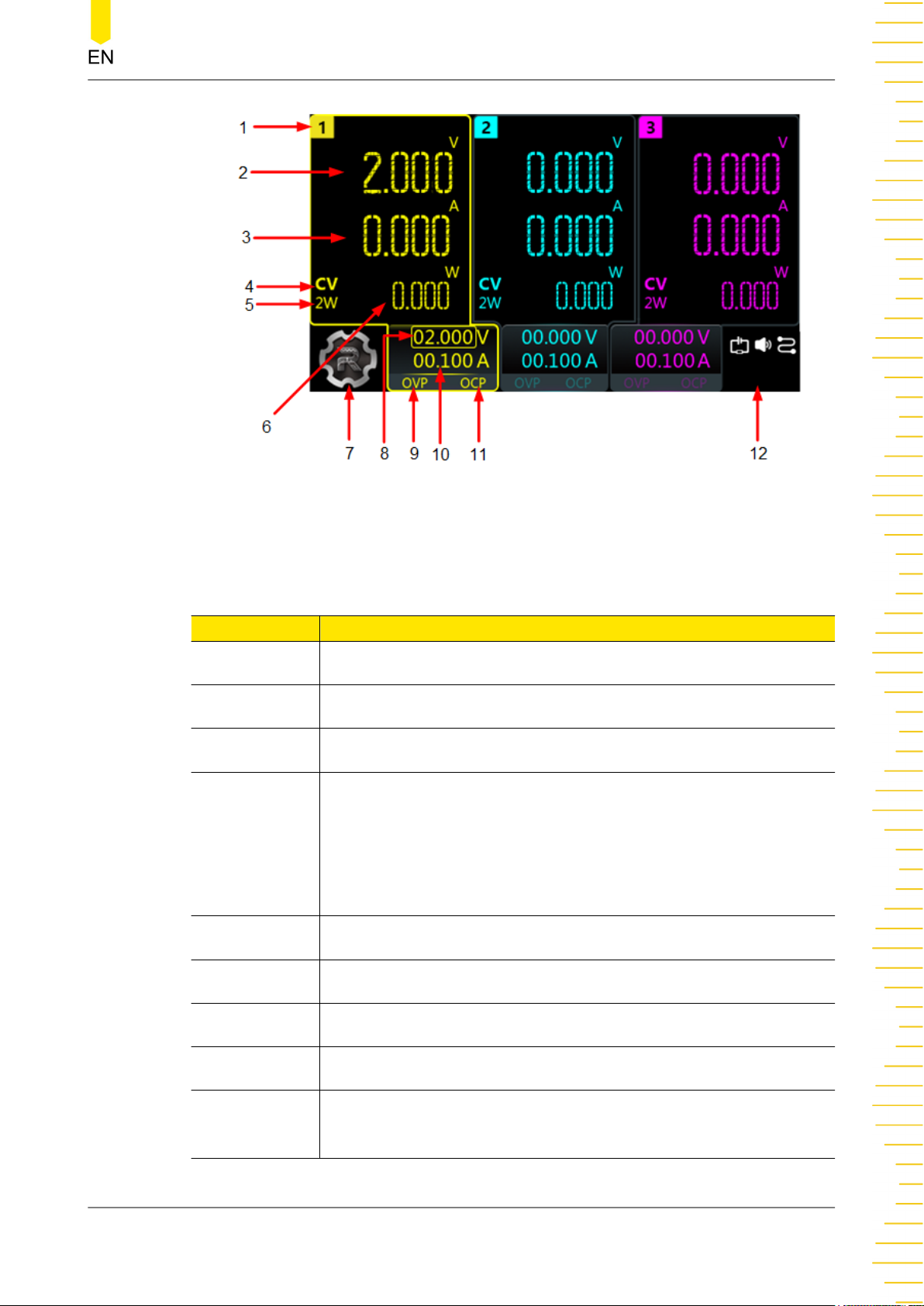
4.5 User Interface
Tap > Display to assess the interface as shown in the figure below. This section
introduces the meter-view display of the power supply.
The table describes the relationship
between the frequency and voltage of the
input power, and fuse rating.
DP900 User Guide
18
Copyright ©RIGOL TECHNOLOGIES CO., LTD. All rights reserved.
Quick Start
Figure 4.6 User Interface
Table 4.2 User Interface Description
No. Description
1 Channel identifier
2 Actual output voltage
3 Actual output current
Output mode
CV: The output is in constant voltage mode.
4
CC: The output is in constant current mode.
UR: The output is unregulated.
5
2-Wire sense connection
6 Actual output power
7 Navigation icon
8 Voltage setting value
9 Over-voltage protection (OVP) status indicator, indicating the
present OVP on/off state
Copyright ©RIGOL TECHNOLOGIES CO., LTD. All rights reserved.
DP900 User Guide
19
Quick Start
No. Description
10 Current setting value
11 Over-current protection (OCP) status indicator, indicating the
present OCP on/off state
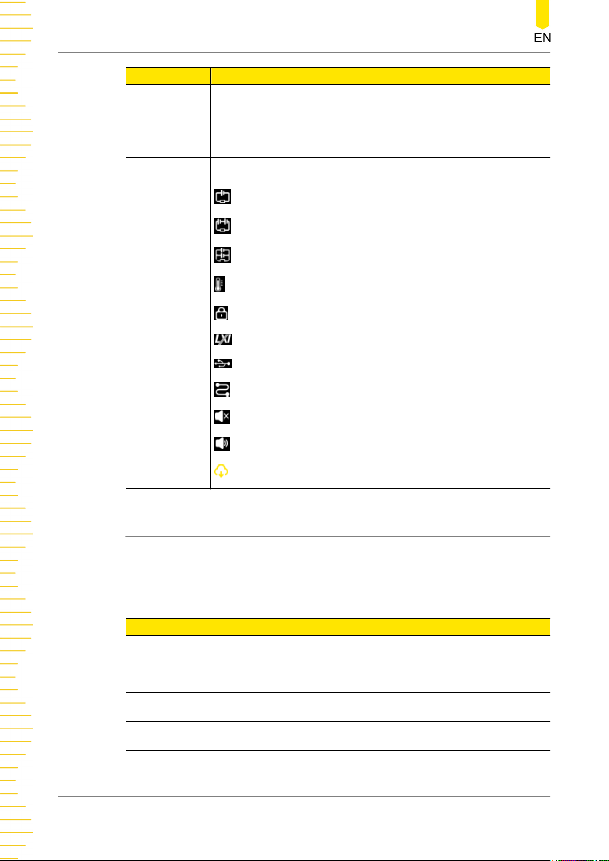
The following icons indicate the system status.
: CH1 and CH2 are independent of each other.
: CH1 and CH2 are connected in series.
: CH1 and CH2 are connected in parallel.
: over-temperature protection is tripped.
12
: the screen is locked.
: network connected.
: a USB device is detected.
: the instrument is in remote control.
: the beeper is turned off.
: the beeper is turned on.
: downloading the firmware upgrade file.
4.6 Connecting to Power
DP900 series power supply supports various AC power inputs. The AC selector setting
on the rear panel differs when input power is different, as shown in the table below.
Table 4.3 AC input power specifications (including AC selector setting)
DP900 User Guide
20
AC input power AC selector
100 Vac±10%, 50 Hz to 60 Hz 100
120 Vac±10%, 50 Hz to 60 Hz 120
220 Vac±10%, 50 Hz to 60 Hz 220
230 Vac±10% (Max. 250 Vac), 50 Hz to 60 Hz 230
Please connect the power strictly following the steps below.
Copyright ©RIGOL TECHNOLOGIES CO., LTD. All rights reserved.
1. Check the Input Power
Quick Start
Please make sure that the input AC power fulfills the requirements in
input power specifications (including AC selector setting)
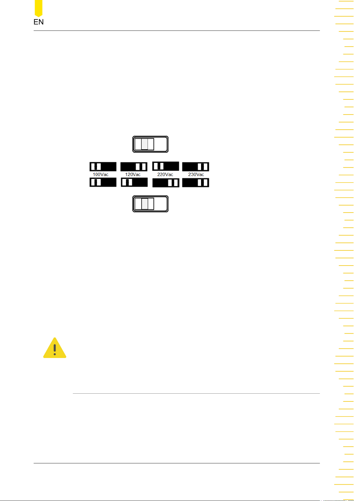
2. Check the AC Voltage Selector on the Rear Panel
Please make sure that the AC voltage selector (100, 120, 220, or 230) on the rear
panel is set to match the actual input voltage. To change the input AC voltage
selector on the power supply, use the two AC selector switches on the rear panel of
the power supply as shown below.
Please set the switches following the diagram above. For example, to select 100 V,
slide both switches to the left; to select 220 V, slide the upper switch to the left and
the lower switch to the right.
.
Table 4.3 AC
3. Check the Fuse
The instrument has been equipped with the specified fuse when it leaves factory.
Please make sure that the fuse matches the actual input voltage by referring to
“Input power requirement” or
4.
Connect to AC Power
Please connect the instrument to AC power using the power cord provided in the
accessories.
WARNING
To avoid electric shock, please make sure that the instrument is correctly grounded.
4.7 Power-on Inspection
Press the power key on the front panel to switch on the instrument. During the startup process, the instrument performs a series of self-tests. If the instrument passes the
self-test, the welcome interface will be displayed; otherwise, the corresponding selftest failure information will be displayed.
Replacing the Fuse
.
Copyright ©RIGOL TECHNOLOGIES CO., LTD. All rights reserved.
DP900 User Guide
21

Quick Start
TIP
If you want to power on the instrument again after powering it off, please make sure that the
time interval between the two power-on operations is greater than 5 s.
4.8 Connecting the Outputs
This series power supply provides three-channel outputs, which share the same
connection method. Please follow the instructions below to connect the outputs.
Method 1: Connect wires to the front of the terminals as shown in (A).
Method 2: Rotate the terminal block screws counter-clockwise and connect wires to
the terminals in location (B). Then rotate the screws clockwise to tighten the wires.
This method can help avoid errors caused by the terminal resistance.
TIP
As the output terminals of DP932U are safety sockets, “Method 2” is not supported.
CAUTION
Turn off AC power before making front panel connections. All wires and straps must be
properly connected to prevent currents from damaging the loads.
4.9 Replacing the Fuse
The fuse rating required depends on the instrument model and actual input voltage,
as shown in the table below. You can also refer to
specifications (including AC selector setting)
Table 4.3 AC input power
.
DP900 User Guide
22
Copyright ©RIGOL TECHNOLOGIES CO., LTD. All rights reserved.

Quick Start
Table 4.4 Fuse Rating
AC Input Voltage Fuse Rating
100 Vac/120 Vac T6.3 A 250 Vac
220 Vac/230 Vac T3.15 A 250 Vac
If you need to replace the fuse, please follow the steps below.
1. Power off the instrument and remove the power cord.
2. Insert a small straight screwdriver into the slot at the power socket and pry out the
fuse holder gently.
3. If necessary, please adjust the AC selector setting manually to select the voltage
that matches the actual input voltage (please refer to
4. Remove the original fuse and insert the proper fuse into the fuse holder (please
refer to the “Input power requirement” or
Replacing the Fuse
5. Re-insert the fuse holder into the power socket (please pay attention to the
direction).
WARNING
To avoid personal injury, please power off the power supply before replacing the fuse; to
avoid electric shock or fire, select the input power that matches the actual input voltage
and use the correct fuse before connecting to power.
4.10 Using the Built-in Help System
Tap > Help to enter the help interface as shown in the figure below. The built-in
help system can help you learn about the instrument, obtain a list of help topics, and
update instrument firmware.
Connecting to Power
).
).
Copyright ©RIGOL TECHNOLOGIES CO., LTD. All rights reserved.
DP900 User Guide
23

Quick Start
Figure 4.7 Help Interface
About
Tap About to view the system information of the instrument, including the instrument
model number, serial number, firmware version, and calibration time.
Help
Help to view the help information for front-panel keys or menu keys. You can tap
Tap
a function key topic at the left side to obtain a detailed description of its function.
Upgrade
Upgrade to access the software upgrade interface. You can read the USB storage
Tap
device and tap Upgrade to update instrument firmware. You can also connect the
instrument to network and then tap Remote to download the firmware upgrade file
is displayed in the notification area in the process). After the file is downloaded,
(
the instrument restarts in 2 seconds and starts to upgrade.
Others
Others to enter the interface in which you can obtain the following help topics:
Tap
DP900 User Guide
24
• View the last displayed message
• View remote command error queue
• Contact RIGOL Technical Support
• Open source statement
Copyright ©RIGOL TECHNOLOGIES CO., LTD. All rights reserved.

Using the Protection Function
5
Using the Protection Function
Each channel output has independent over-voltage protection (OVP) and over-current
protection (OCP) functions. The “OVP”/“OCP” status indicator is lit when a
protection function is enabled.
Overvoltage Protection (OVP)
When OVP is enabled, the output will be disabled when the output voltage reaches
the voltage limit setting.
Tap
of the channel labels at the bottom to open the meter view for a single channel. For
example, you can configure CH1 output settings in its meter view, as shown in the
figure below.
> Display to enter the meter view for multiple outputs. Then you can tap one
Figure 5.1 CH1 Output Settings Interface
You can set the OVP value in the following ways.
• Tap the “OVP” input field and set the limit value with the pop-up numeric
keypad.
• Rotate the knob or use the arrow keys to select the “OVP” input field. Then
press the knob to enter the editing mode. After that, you can either use the front
panel numeric keypad to directly enter the value or use the up/down arrow keys
to increment or decrement the value in the specified digit place. Press the knob
again to disable the editing mode.
Copyright ©RIGOL TECHNOLOGIES CO., LTD. All rights reserved.
DP900 User Guide
25

Using the Protection Function
After finishing the voltage limit setting, you can click or tap the “OVP” on/off
button to turn ON or OFF the OVP function.
Overcurrent Protection (OCP)
When OCP is enabled, the output will be disabled when the output current reaches
the current limit setting.
You can tap
> Display to enter the meter view for multiple outputs. Then you can
tap one of the channel labels at the bottom to open the meter view for a single
channel. For example, you can configure CH1 output settings in its meter view, as
shown in
Figure 5.1
.
You can set the OCP value in the following ways.
• Tap the “OCP” input field and set the value with the pop-up numeric keypad.
• Rotate the knob or use the arrow keys to select the “OCP” input field. Then
press the knob to enter the editing mode. After that, you can either use the front
panel numeric keypad to directly enter the value or use the up/down arrow keys
to increment or decrement the value in the specified digit place. Press the knob
again to disable the editing mode.
After finishing the current limit setting, you can click or tap the “OCP” on/off
button to turn ON or OFF the OCP function.
OCP Delay
The power supply may momentarily has a peak current value beyond the OCP value
when it is turned on, when an output value is programmed, or when the output load
is connected. In most cases, these temporary conditions would not be considered an
over-current protection fault, and you do not need to disable the output. The series
power supply ignores this status bit during the specified delay period (10 ms by
default). Once the OCP delay time has expired and if the current is still beyond the
limit, the output will shut down.
DP900 User Guide
26
You can also set the OCP delay period by sending :OUTPut:OCP:DELAy [CH1|CH2|
CH3], {<value>|MINimum|MAXimum} SCPI command (refer to the series
Programming Guide
). The delay can be programmed from 0 to 1000 ms.
Copyright ©RIGOL TECHNOLOGIES CO., LTD. All rights reserved.

Constant Voltage Output
6
Constant Voltage Output
The series power supply provides three output modes: constant voltage (CV),
constant current (CC), and unregulated (UR). In CV mode, the output voltage equals
to the voltage setting value, and the output current is determined by the load;
whereas in CC mode, the output current equals to the current setting value, and the
output voltage is determined by the load. UR mode is the unregulated state between
CV and CC mode. This chapter introduces how to make the instrument operate in CV
mode.
Operation Procedures:
1.
Connect the load to the channel output terminals (please refer to
Outputs
CAUTION
While making connections, pay attention to the polarity to avoid damaging the
instrument or the devices connected to the instrument.
2. Press the power key to start the instrument and the meter view appears.
3.
Set the voltage
).
Connecting the
Method 1:
You can use the front-panel parameter input area to set the voltage.
a. Use the knob or arrow keys to select the voltage field in meter view or in
channel output settings interface.
b. Press the knob and the input box turns blue, indicating that the selected field
can be edited.
c. Use the left/right arrow keys to select the digit place and then rotate the knob
or use the up/down arrow keys to adjust the value in the selected place. You
can also directly set the voltage by using the front-panel numeric keypad. The
default unit is V.
d. Press the knob again to disable the editing mode.
TIP
In meter view, if you select a current "Set" field to edit, you can still set the voltage by using
the front-panel numeric keypad to set the value and then pressing the unit selection key
/ .
Method 2:
You can also use the touch screen function to set the voltage.
Copyright ©RIGOL TECHNOLOGIES CO., LTD. All rights reserved.
DP900 User Guide
27

Constant Voltage Output
In the channel output settings interface, tap the voltage “Set” field and use the
pop-up numeric keypad to enter the value and unit.
You can tap on the virtual keypad or press on the front panel to delete
the character before the cursor.
4.
Set the current
Method 1:
You can use the front-panel parameter input area to set the current.
a. Use the knob or arrow keys to select the current field in meter view or in
channel output settings interface.
b. Press the knob and the input box turns blue, indicating that the selected field
can be edited.
c. Use the left/right arrow keys to select the digit place and then rotate the knob
or use the up/down arrow keys to adjust the value in the selected place. You
can also directly set the current by using the front panel numeric keypad. The
default unit is A.
d. Press the knob again to disable the editing mode.
TIP
In meter view, if you select a voltage "Set" field to edit, you can still set the current by using
the front panel numeric keypad to set the value and then pressing the unit selection key
/ .
Method 2:
You can also use the touch screen function to set the current.
In the channel output settings interface, tap the current “Set” field and use the
pop-up numeric keypad to enter the value and unit.
You can tap
on the virtual keypad or press on the front panel to delete
the character before the cursor.
5. Set the OCP
Set the OCP value (refer to
Using the Protection Function
) and then tap OCP
on/off button to enable the OCP function. The output will be disabled
automatically when the actual output current reaches the OCP value.
DP900 User Guide
28
6.
Enable the output
Pressing the channel on/off key
can turn on the respective channel output.
When a channel is turned on, its on/off key is illuminated. Rather, when the
Copyright ©RIGOL TECHNOLOGIES CO., LTD. All rights reserved.

Constant Voltage Output
channel is turned off, the light will be off. You can press to turn all outputs on
or off simultaneously.
WARNING
To avoid electric shock, please turn on the output after the output terminals are
correctly connected.
7. Check the output mode
In CV mode, the displayed output mode is "CV"; if "CC" is displayed, increase the
current value properly and the power supply will switch to CV mode automatically.
TIP
In CV output mode, when the load current is greater than the current setting value, the power
supply will switch to CC mode automatically. At this time, the output current equals to the
current setting value, and the output voltage can be calculated by the current times the load
impedance.
Copyright ©RIGOL TECHNOLOGIES CO., LTD. All rights reserved.
DP900 User Guide
29

Constant Current Output
7
Constant Current Output
In CC mode, the output current equals to the current setting value, and the output
voltage is determined by the load. This chapter introduces how to make the
instrument operate in CC mode.
Operation Procedures:
Connect output terminals
1.
Please connect the load to the channel output terminals on the front panel (please
refer to
2. Press the power switch to start the instrument.
3. Set the voltage
Set your desired voltage value (refer to
4. Set the current
Set your desired current value (refer to
5. Set the OVP
Connecting the Outputs
).
Constant Voltage Output
Constant Voltage Output
).
).
Set the proper OVP value (refer to
the OVP function by tapping
automatically when the actual output voltage reaches the OVP value.
6.
Enable the output
Please turn on the output (refer to
WARNING
To avoid electric shock, please turn on the output after the output terminals are
correctly connected.
7. Check the output mode
In CC mode, the output mode displayed should be "CC"; if "CV" is displayed,
increase the voltage value properly and the power supply will switch to CC mode
automatically.
TIP
In CC mode, when the load voltage is greater than the voltage setting value, the power supply
will switch to CV output mode automatically. At this time, the output voltage equals to the
voltage setting value, and the output current can be calculated by the voltage divided by the
load impedance.
Using the Protection Function
OVP on/off button. The output will be disabled
Constant Voltage Output
) and then enable
).
DP900 User Guide
30
Copyright ©RIGOL TECHNOLOGIES CO., LTD. All rights reserved.

Series/Parallel Connections
8
Series/Parallel Connections
Connecting two or more isolated channels in series provides a greater voltage
capability while connecting two or more isolated channels in parallel provides a
greater current capability. The series power supply supports both internal and
external series/parallel connections.
TIP
• The three channels of the power supply are electrically isolated with independent
outputs. For a single power supply, any two of the three channels can be externally
connected in series/parallel.
• Isolated channels of different power supplies can be externally connected in series/
parallel.
• CH1 and CH2 can be internally connected in series/parallel.
• When in internal series mode, CH1 and CH2 cannot be externally connected in parallel;
when in internal parallel connection mode, CH1 and CH2 cannot be externally connected
in series.
• The parameter settings for series and parallel connections must comply with the safety
requirements.
8.1 Series Connections
Connecting outputs in series provides a greater voltage capability than can be
obtained from a single output. The total voltage is the sum of the individual voltages
of all channels connected in series. To connect outputs in series, you need to ensure
identical current ratings for each channel.
WARNING
To avoid shock hazard, please do not touch the output terminals when the output voltage
exceeds 60 V in series mode.
Internal Series Connections
This series power supply supports internal series connection for CH1 and CH2. In
internal series connection mode, the output voltage (up to 64 V) is twice the voltage
setting. The output voltage and current are displayed in CH1 meter view, as is shown
in the figure below.
Copyright ©RIGOL TECHNOLOGIES CO., LTD. All rights reserved.
DP900 User Guide
31

Series/Parallel Connections
The figure below shows how to connect front output terminals to a single load in
internal series mode. Please refer to
connection.
Figure 8.1 Series Output Interface
Output Connection
for internal parallel
DP900 User Guide
32
TIP
• In internal series/parallel connections, CH1 and CH2 always have identical voltage and
current settings.
• The output voltage displayed in CH1 meter view is twice the voltage setting. CH2 has no
reading.
• In internal series mode, the output voltage at the terminal is twice the voltage setting. To
avoid damage to the load, please set proper voltage values
External Series Connections
This series power supply supports external series connection for multiple channels
(from a single power supply or multiple power supplies). The figure below illustrates
how to connect two channels when in external series mode.
Copyright ©RIGOL TECHNOLOGIES CO., LTD. All rights reserved.

Series/Parallel Connections
Figure 8.2 External Series Circuit
Operation Procedures:
1. Connect the power supply to load as shown in the figure above. Pay attention to
the polarity when making connections.
2. Set proper voltage, current, and over-current protection value for each channel
(refer to
Constant Voltage Output
channels connected in series should be set to CV mode and have identical current
setting value and OCP value.
CAUTION
Please make sure that all the channels connected in series operate in CV mode. One of the
channels operating in CC mode can cause unregulated output mode for the other
channels.
8.2 Parallel Connections
Connecting outputs in parallel provides a greater current capability than can be
obtained from a single output. The total current is the sum of the individual currents
of all channels connected in parallel. To connect outputs in parallel externally, you
need to ensure identical voltage value and OVP value for each channel.
) and turn on the channel outputs. All the
Internal Parallel Connections
This series power supply supports internal parallel connection for CH1 and CH2. In
internal parallel connection mode, the output current (up to 6 A) is twice the current
setting. The output voltage and current are displayed in CH1 meter view, as is shown
in the figure below.
Copyright ©RIGOL TECHNOLOGIES CO., LTD. All rights reserved.
DP900 User Guide
33

Series/Parallel Connections
Figure 8.3 Parallel Output Interface
The figure below shows how to connect front output terminals to a single load in
internal parallel mode. Please refer to
Output Connection
for channel connection.
TIP
In internal series/parallel connections, CH1 and CH2 always have identical voltage and current
setting value.
External Parallel Connections
DP900 User Guide
34
This series power supply supports external parallel connection for multiple channels
(from a single power supply or multiple power supplies). The figure below illustrates
how to connect two outputs in external parallel.
Copyright ©RIGOL TECHNOLOGIES CO., LTD. All rights reserved.

Series/Parallel Connections
Figure 8.4 External Parallel Circuit
Operation Procedures:
1. Connect the power supply to load as shown in the figure above. Pay attention to
the polarity when making connections.
2. Set proper parameters for each channel (refer to
Constant Current Output
) and turn on the output of each channel. All channels can
Constant Voltage Output
and
work in CV mode or CC mode.
CAUTION
All the channels can work in CV or CC mode according to the actual need of the load.
Copyright ©RIGOL TECHNOLOGIES CO., LTD. All rights reserved.
DP900 User Guide
35

Arb Function
9
Arb Function
The Arbitrary function of DP900 (not available for DP932E) series power supply
enables you to generate freely programmable waveforms which can be reproduced
within the limit settings for voltage and current. You can set the repetition cycle for
the arbitrary waveform as well as the output voltage/current and time for each group
of data. Moreover, the instrument has multiple built-in waveform templates for you to
select and edit. You can set your waveform parameters based on those templates. The
instrument will output waveforms according to the parameters set.
Press
below. Then tap the channel selection drop-down button at the lower-left corner of
the interface to select a channel to control. The menu keys and their functions are as
follows:
• Run/Stop:
Turn on or off the arbitrary waveform generator.
• Setting:
Open the Arb settings interface to set the output properties for the arbitrary
waveform.
or tap > Arb to enter the Arb main interface, as shown in the figure
• Import:
Read Arb file.
• Export:
Save the Arb parameters edited.
• Edit:
Access the Arb editor to edit the data.
DP900 User Guide
36
Figure 9.1 Arb Main Interface
Copyright ©RIGOL TECHNOLOGIES CO., LTD. All rights reserved.

9.1 Setting Arb Properties
After entering the Arb main interface, tap Setting to enter the Arb settings interface
as shown in the figure below. The selected channel is highlighted at the lower-left
corner of the interface.
Arb Function
Figure 9.2 Arb Settings Interface
In the interface, you can set the following output properties for the arbitrary
waveform.
Repetition Cycle
The repetition cycle is the number of times that the arbitrary waveform is repeated
based on the preset voltage/current and time. You can tap the
the desired repetition cycle by using the touch screen or the front-panel numeric
keypad. The repetition cycle can be set from 1 to 99999. Entering “0” in the field
will set the repetition cycle to “infinity”.
End State
End state is the instrument state after the output sequence completes the output of
all voltage/current values when the repetition cycle is set to a finite value. You can tap
EndState drop-down button to select “Off” or “Last”.
the
• Off: The output of the selected channel is turned off automatically after the
output sequence completes.
Rep. input field to set
• Last: The instrument remains at the last voltage and current values after the
output sequence completes.
Copyright ©RIGOL TECHNOLOGIES CO., LTD. All rights reserved.
DP900 User Guide
37

Arb Function
TIP
If the repetition cycle is set to “Infinity”, the end state is not available.
Run Mode
Run mode is the output state of the selected channel once the generator is turned on.
You can tap the RunMode drop-down button to select “Continuous” or “Single”.
• When the run mode is set to “Continuous”, tap
Run(Cont) in the Arb main
interface and the instrument will repeat the sequence continuously based on the
number of data groups and repetition cycle currently set.
• When the run mode is set to “Single”, tap
Run(Sgl) and the button for running
a single arbitrary point will be displayed, as shown in the figure below. Each
time you tap , the instrument will output a single group of data in order. The
current output group number and repetition cycle are displayed at the bottom
of the interface.
DP900 User Guide
38
Trigger Source
Trigger source specifies the way of starting the output of the arbitrary sequence. You
can tap the
TrigSrc drop-down button to select “Manual” or “BUS”.
• Manual:
- Selects the Run/Stop key as a trigger source. When the run mode is set to
“Continuous”, tap
Run(Cont) and the instrument will repeat the
sequence continuously based on the number of data groups and repetition
cycle currently set.
- When the run mode is set to “Single”, tap
Run(Sgl) and then tap to
output a single group of data.
Copyright ©RIGOL TECHNOLOGIES CO., LTD. All rights reserved.

Arb Function
• BUS: Selects a remote command as a trigger source. You can send SCPI
commands to control the Arb sequence output. In the Arb main interface, tap
Run(Cont) or Run(Sgl) and a prompt message “Wait for Trigger signal...” will
be displayed. The instrument will start or stop the waveform output according to
the received SCPI command. Please refer to
DC Power Supply Programming Guide
DP900 Series Programmable Linear
for available SCPI commands.
Apply or Back
Apply to save the current settings and return to the Arb main interface.
Tap
Otherwise, tap Back to cancel the current settings and return to the main interface.
TIP
The settings are valid only for the selected channel. You can change the selected channel in
Figure 9.2
select the channel in
through pressing the specified channel selection key on the front panel. You can also
Figure 9.1
using the touch screen.
9.2 Arb Editor
After entering the Arb main interface, you can tap Edit to access the Arb editor
interface, as shown in the figure below. The Arb editor allows you to create each
single point of a waveform and freely edit individual points. You can also edit the Arb
parameters based on the instrument's built-in waveform templates.
Figure 9.3 Arb Editor Interface
As shown in the figure above, the table displays 4 groups of data per page. You can
view and edit data of other groups in the following ways.
• Tap Prev or Next to turn pages.
Copyright ©RIGOL TECHNOLOGIES CO., LTD. All rights reserved.
DP900 User Guide
39

Arb Function
• Tap the page input field and input the page number to jump to by using the
pop-up virtual keypad or the front-panel numeric keypad.
• Tap the “No.” cell at the upper-left of the table and input the number to jump
to the specified row by using the pop-up virtual keypad or the front-panel
numeric keypad.
9.2.1 Inserting a Single Point
In the Arb editor interface, you can tap Single to insert one group of data in the
currently selected row (1 V default voltage, 1 A default current, and 1 s default time).
You can set the voltage/current/time for each group by using the touch screen or the
numeric keypad on the front panel.
TIP
• If the currently selected row is empty and the row above the selected row has data
inserted, tap Single and one group of data will be inserted in the selected row.
• If the currently selected row has data inserted, tap Single and a group of data will be
inserted in the selected row with the original group of data moved to the next row.
9.2.2 Editing Waveform Templates
The instrument provides multiple built-in output templates based on which you can
create and edit arbitrary waveforms.
Tap Templet to open the template editing menu, as shown in the figure below. You
can edit and create your desired waveform in the following steps.
DP900 User Guide
40
Figure 9.4 Template Editing Menu
1.
Select Waveform Templates
Copyright ©RIGOL TECHNOLOGIES CO., LTD. All rights reserved.

Arb Function
Tap the Wave drop-down button to select a waveform template. Available
waveform templates include Sine, Pulse, Ramp, Stair UP, Stair Dn, StairUpDn, Exp
Rise, and Exp Fall.
- Sine
The Sine waveform is as shown in the figure below. Setting the maximum and
minimum value creates the amplitude. Setting the period (T) and time interval
creates the total number of points (P) in a complete period. Thus, a Sine
waveform is created. Setting the inserted groups (G) determines the number of
groups to be inserted in the Arb editor.
- Pulse
The Pulse waveform is as shown in the figure below. Setting the maximum and
minimum value creates the amplitude. Setting the positive pulse width (t)
determines the duration of high levels. The currently set period (T) minus the
positive pulse width (t) is the duration of low levels. Setting the inserted groups
(G) determines the number of groups to be inserted in the Arb editor.
- Ramp
The Ramp waveform is as shown in the figure below. Setting the maximum and
minimum value creates the amplitude. Setting the period (T) and time interval
creates the total number of points (P) in a complete period. Setting the
symmetry (Sym) creates the Ramp waveform. The rising edge of the Ramp
waveform has int (P*Sym)
[1]
points and the falling edge has P-int (P*Sym)
points.
Copyright ©RIGOL TECHNOLOGIES CO., LTD. All rights reserved.
DP900 User Guide
41

Arb Function
[1]
Note
: int (P*Sym) refers to rounding P*Sym (to discard the decimal part).
- Stair Up
The Stair Up waveform is as shown in the figure below. Setting the maximum
(MAX), minimum (MIN), period, and total number of steps (N) creates the Stair
Up waveform. The number of steps (N) ranges from MIN to MAX. The step size
is ( MAX-MIN )/(N-1). Interval=Period/Number of Steps.
- Stair Dn
The Stair Dn waveform is as shown in the figure below. Setting the maximum
(MAX), minimum (MIN), period, and total number of steps (N) creates the Stair
Dn waveform. The number of steps (N) ranges from MIN to MAX. The step size
is (MAX-MIN )/(N-1). Interval=Period/Number of Steps.
- Stair UpDn
The Stair UpDn waveform is as shown in the figure below. Setting the maximum
(MAX), minimum (MIN), period (T), and total number of steps (N) creates the
Stair UpDn waveform. When N is odd, the waveform rises from MIN to MAX by
step size of (MAX-MIN )/int(N/2) and then drops to MIN by the same step size.
When N is even, the waveform rises from MIN to MAX by step size of (MAX-
DP900 User Guide
42
Copyright ©RIGOL TECHNOLOGIES CO., LTD. All rights reserved.

Arb Function
MIN)/{(N/2)-1} and then drops to MIN by step size of (MAX-MIN)/(N/2).
Interval=Period/Number of Steps.
- Exp Rise
The Exp Rise waveform is as shown in the figure below. Setting the maximum
(MAX), minimum (MIN), inserted groups (total number of points, denoted by P),
interval, and rise index (denoted by RiseIndex) creates the Exp Rise waveform.
The waveform function is (MAX-MIN)*(1-e
-i*RiseIndex/P
); wherein, “i” is
independent variable ranging from 0 to (P-1).
- Exp Fall
The Exp Fall waveform is as shown in the figure below. Setting the maximum
(MAX), minimum (MIN), inserted groups (total number of points, denoted by P),
interval, and fall index (denoted by FallIndex) creates the Exp Fall waveform. The
waveform function is (MAX-MIN)*e
-i*FallIndex/P
; wherein, “i” is independent
variable ranging from 0 to (P-1).
TIP
When the template selected is Exp Rise or Exp Fall, the maximum or minimum value cannot
be reached due to the characteristic of the exponential function itself. The available range
depends on the rise/fall index currently set. The larger the rise/fall index, the wider the
Copyright ©RIGOL TECHNOLOGIES CO., LTD. All rights reserved.
DP900 User Guide
43

Arb Function
range, as shown in the figures below (maximum=8, minimum=0, total number of
points=100, rise index/fall index: 1, 4, 7 and 10).
2. Select Voltage/Current to Edit
Tap the Object drop-down button and select “Voltage” or “Current” to edit.
- Voltage: When voltage is selected, the output current of all groups is fixed. You
can tap the Current input field to set the current value using the touch screen
or the parameter input area on the front panel.
- Current: When current is selected, the output voltage of all groups is fixed. You
can tap the Voltage input field to set the voltage value using the touch screen
or the parameter input area on the front panel.
3. Edit Arb Parameters
When selecting different waveform templates, you need to edit different
parameters. Please refer to the table below for details.
Table 9.1 Arb Parameters (Template)
Template Parameters
Sine Max, Min, Period, Interval, Groups, Invert On/Off
DP900 User Guide
44
Pulse Max, Min, Period, Positive Pulse Width, Groups, Invert On/Off
Ramp Max, Min, Period, Interval, Groups, Symmetry, Invert On/Off
Stair Up Max, Min, Period, Steps, Groups
Stair Dn Max, Min, Period, Steps, Groups
StairUpDn Max, Min, Period, Steps, Groups
Copyright ©RIGOL TECHNOLOGIES CO., LTD. All rights reserved.

Template Parameters
Exp Rise Max, Min, Groups, Interval, Exp
Exp Fall Max, Min, Groups, Interval, Exp
- Max
Set the maximum voltage/current of the template currently selected. The
available range is related to the channel currently selected. The max value
should be greater than or equal to the min value currently set.
- Min
Set the minimum voltage/current of the template currently selected. The
available range is related to the channel currently selected. The min value
should be smaller than or equal to the max value currently set.
Arb Function
- Period
Set the duration of a cycle for the waveform currently selected. The max period
is 3600 s.
- Interval
Set the time interval between two points (the time required for the instrument
to output each group of data) of the template currently selected. The maximum
interval is 3600 s.
- Groups
Set the number of points selected from the waveform at equal intervals. The
available range is from 1 to 512.
- Invert
When the template currently selected is Sine, Pulse, or Ramp, if Invert is turned
on, the instrument will first turn the preset waveform upside down and then
create the output waveform.
- Positive Pulse Width
When the template currently selected is Pulse, you can set the positive pulse
width (namely the duration of high levels within a period). The maximum pulse
width is 3600 s. The actual available positive pulse width depends on the period
currently set.
- Symmetry
When the template currently selected is Ramp, you can set the symmetry
(namely the ratio of the duration of the rising edge within a period to the whole
period). The range is from 0% to 100%.
- Steps
Copyright ©RIGOL TECHNOLOGIES CO., LTD. All rights reserved.
DP900 User Guide
45

Arb Function
When the template currently selected is Stair Up, Stair Dn, or Stair UpDn, you
can set the total number of points within a complete period. The available
range is from 3 to 99999.
- Exp
When the template currently selected is Exp Rise, you can set the rise index
which ranges from 0 to 10.
When the template currently selected is Exp Fall, you can set the fall index
which ranges from 0 to 10.
4. Apply Settings
After editing the Arb parameters (template), tap Apply to create the arbitrary
waveform. Its Arb parameters will be displayed in the Arb editor as shown in
9.3
.
Figure
9.2.3 Delete
In the Arb editor interface (
group of data. If the selected row has no data, a prompt message “No data in the
unit” will be displayed.
Tap Clear and a prompt message “Clear all groups?” will be displayed. Tapping Yes
will remove all data in the table.
Figure 9.3
9.3 Import and Export
You can save the Arb parameters to internal or external memory and recall them
when required.
Export
After editing the parameters, you can tap Export to access the store and recall
interface. Select the desired storage path and then tap
pop-up filename input field. A prompt message “Arb file is exported successfully”
will be displayed. The file type is fixed to “.RTF”.
), you can tap Delete to delete the selected
Save. Set the filename in the
DP900 User Guide
46
Import
Tap Import to access the store and recall interface. Select the file that you want to
read and then tap Read. A prompt message “Arb file is imported successfully” is
displayed and the instrument goes back to the Arb main interface. You can edit the
imported Arb file.
Copyright ©RIGOL TECHNOLOGIES CO., LTD. All rights reserved.

9.4 Enabling the Arb Output
After editing the Arb parameters, you can go back to the Arb main interface and turn
on waveform output based on settings in
Arb output interface.
Trigger Source
Arb Function
. The figure below shows the
Figure 9.5 Arb Output Interface
TIP
• Enabling the output will change the channel output value. Please make sure that the
change of the output value will not affect the devices connected to the power supply
before turning on the output.
• When the generator is turned on, you need to turn on the corresponding channel to
ensure valid waveform output.
• When the output is initiated, all the Arb settings and parameters cannot be configured.
Copyright ©RIGOL TECHNOLOGIES CO., LTD. All rights reserved.
DP900 User Guide
47

Analyzer
10
Analyzer
DP900 series power supply provides the Analyzer function for you to analyze the
quality of output signals. Available analysis functions for the 3 channels include
common analysis, pulse current analysis (only for CH1 and CH2), and data logging.
You can press the front-panel
main interface, as shown in the figure below. The label at the upper-left of the
interface indicates the currently selected analysis function (common analysis/pulse
current analysis). The four function keys at the right side allow you to easily configure
the Analyzer settings, execute analysis, print screen, and control labels.
or tap > Analyzer to access the Analyzer
Figure 10.1 Analyzer Main Interface
10.1 Common Analysis
In the Analyzer main interface, tap QicSet to access the quick setup interface. Then
tap Common to enter the common analysis setting interface, as shown in the figure
below. In this interface, you can select the object to analyze and statistical method.
DP900 User Guide
48
Copyright ©RIGOL TECHNOLOGIES CO., LTD. All rights reserved.

Figure 10.2 Common Analysis Setting Interface
Analyzer
10.1.1 Selecting Analysis Object
After entering the common analysis interface, you can tap Object to access the
analysis object setting menu, as shown in the figure below. Select one to three items
from the “Current”, “Voltage”, and “Power” items of CH1, CH2, and CH3.
Then tap OK to go back to the analyzer main interface. Tap Run and the instrument
will execute analysis based on the your selections.
Figure 10.3 Analysis Object Setting Menu
Copyright ©RIGOL TECHNOLOGIES CO., LTD. All rights reserved.
DP900 User Guide
49

Analyzer
10.1.2 Selecting Statistical Method
After entering the common analysis interface, tap Method to pop up the statistical
method setting menu. You can select RT Plot or Trend Plot.
• RT Plot
It displays the analysis object currently selected in real-time plot. In RT Plot
mode, the waveform of the collected signals slowly scrolls from right to left. The
latest data is displayed on the screen.
• Trend Plot
It displays the analysis object currently selected in trend plot. In Trend Plot
mode, the waveform plot area is divided into two parts: the left displays trend
waveform while the right displays real-time data. Real-time data will be drawn
point by point. When the data is out of the screen, it will be compressed and
displayed proportionally in the trend plot. Then, real-time data will be redrawn
from left to right.
DP900 User Guide
50
Copyright ©RIGOL TECHNOLOGIES CO., LTD. All rights reserved.

10.2 Pulse Current Analysis
The pulse current analysis function is only available for CH1 and CH2 of this series
power supply. After entering the quick setup interface, you can tap Pulse Current to
enter the pulse current analysis setting interface, as shown in the figure below.
Analyzer
Figure 10.4 Pulse Current Analysis Setting Interface
1. First select the channel you want to analyze.
2. Tap Pos pulse or Neg pulse to select the pulse current to analyze.
- Positive pulse: Select Pos pulse, and set the upper threshold level in the input
field. In the analysis process, the Analyzer records the number of pulses above
the threshold and the most recent pulse width beyond this upper threshold.
- Negative pulse: Select
field. In the analysis process, the Analyzer records the number of pulses below
the threshold and the most recent pulse width below this threshold.
3. Then tap
will execute analysis based on your selections. The analysis interface is shown in
the figure below. The analysis results are at the lower part of the interface.
OK to return to the Analyzer main interface. Tap Run and the instrument
Neg pulse, and set the lower threshold level in the input
Copyright ©RIGOL TECHNOLOGIES CO., LTD. All rights reserved.
DP900 User Guide
51

Analyzer
Figure 10.5 Pulse Current Analysis Interface
10.3 Data Logging
The data logging function allows you to record waveform data collected in real time.
The data is stored to a *.ROF file in the predefined target folder.
After entering the quick setup interface, you can tap Log to enter the interface as
shown in the figure below. You can enable/disable the data logging function and set
the target location to save the data.
DP900 User Guide
52
Figure 10.6 Log Setting Interface
Storage Path
Tap Save to input field to access the Store and Recall interface. Select the desired
storage path and then tap
The data is stored to a file with .ROF extension.
Save. Set the filename in the pop-up filename input field.
Copyright ©RIGOL TECHNOLOGIES CO., LTD. All rights reserved.

Analyzer
TIP
You can store files in the instrument's internal memory or an external USB device. The
maximum size of log file saved in internal memory is 20M. The size of the file saved in the
external USB device depends on the memory size of the device.
Logger On/Off
Tap the Logger on/off toggle switch to turn on/off the logger.
• Select ON to enable the data logging function. When turning on the Analyzer
(through tapping Run in the Analyzer main interface), the instrument stores the
waveform data collected in real time at the current sample rate. The logging
finishes as the analysis stops. The file is saved in the specified location.
• Select OFF to disable the data logging function. When the Analyzer is on, the
system will not perform any data logging.
TIP
• If the storage location is not changed, the data logged at different times will be saved to
the same file.
• Record at least 1 point to save the file.
10.4 Print Screen
In the analyzer main interface, you can tap PrtScn to capture and save the current
screen. By default, the screen images are stored in internal memory of the instrument.
If a USB storage device is detected, the images will be saved to the USB device under
the target folder. A dialog window will pop up indicating the file location. The saved
file is in .BMP format.
The first screen image is named “Analyzer0.BMP” by default. The number next to
“Analyzer” in the name increments by 1 each time a new image is captured and
saved under the current path. For example, the second screen image is named
“Analyzer1.BMP”.
10.5 Label Control
Tap label Control in the Analyzer main interface to hide or display the labels of
analysis objects.
Copyright ©RIGOL TECHNOLOGIES CO., LTD. All rights reserved.
DP900 User Guide
53

Trigger
11
Trigger
DP900 series power supply supports trigger input and trigger output via the rearpanel Digital I/O interface (optional for DP932U and not available for DP932E).
• Trigger Input:
The data lines of the digital I/O interface receive external trigger signal. The
source under control (namely the selected output channel) turns on/off the
output or inverts the output state when the preset trigger condition is met.
• Trigger Output:
The data lines of the digital I/O interface output a high/low level signal when the
control source (namely the selected output channel) turns on the output.
The 4 data lines of the digital I/O interface are mutually independent and can be used
for trigger input or trigger output separately.
The digital port connections are shown in the figure below.
DP900 User Guide
54
Figure 11.1 Digital Port Connections
Operation Procedures:
1. Connect the wires to the terminal block connector according to the figure above
(pay attention to the corresponding relations).
2. Insert the terminal block connector into the digital I/O terminal port on the rear
panel (pay attention to the corresponding relations).
Copyright ©RIGOL TECHNOLOGIES CO., LTD. All rights reserved.

Trigger
Tap >Trigger to access the trigger setting interface, as shown in the figure below.
You can tap Trigger Input or Trigger Output to access the corresponding interface.
11.1 Trigger Input
When the specified data line receives input signal that meets the current
the specified source under control will turn on/off the output, or toggle the output
state according to the setting in
Tap > Trigger at the lower-left of the screen. Then select Trigger Input to open
the trigger input setting interface, as is shown in the figure below.
Figure 11.2 Trigger Setting Interface
Output Response
.
Trigger Type
,
Copyright ©RIGOL TECHNOLOGIES CO., LTD. All rights reserved.
DP900 User Guide
55

Trigger
Figure 11.3 Trigger Input Setting Interface
Data Line
Select a data line (D1, D2, D3, or D4) you wish to configure. The data line label is lit
after selected. You can configure the trigger settings for the four data lines
respectively.
Trigger Input On/Off
Tap the
TrigIn on/off button to enable or disable the respective trigger input settings
for the selected data line.
Source Under Control
In the
Channel item, you can select one or more of CH1, CH2, and CH3 as the source
under control by ticking the box.
Trigger Type
Tap the
TrigType drop-down button to select to trigger on the rising edge, falling
edge, high level, or low level of the input signal.
DP900 User Guide
56
TIP
For the input signal, high level ranges from 2.5 V to 3.3 V, low level from 0 V to 0.8 V, and the
noise tolerance is 0.4 V.
Output Response
Tap the Response drop-down menu to set the trigger response type to "OutOn",
"OutOff”, or “OutFlip”.
Copyright ©RIGOL TECHNOLOGIES CO., LTD. All rights reserved.

• OutOn: Turns on the output of the channel currently selected as the source
under control when the trigger condition is met.
• OutOff: Turns off the output of the channel currently selected as the source
under control when the trigger condition is met.
• OutFlip: Toggles the channel output state. That is, turns off the channel when the
current channel is on, or turns on the channel when the current channel is off.
11.2 Trigger Output
The specified data line outputs a high/low level signal when the control source turns
on the output.
Trigger
Tap > Trigger and select Trigger Output to access the trigger output setting
interface, as shown in the figure below.
Figure 11.4 Trigger Output Setting Interface
Data Line
Select a data line (D1, D2, D3, or D4) you wish to configure. The data line label is lit
after selected. You can configure the trigger settings for the four data lines
respectively.
Trigger Output On/Off
Tap the
settings for the selected data line.
Copyright ©RIGOL TECHNOLOGIES CO., LTD. All rights reserved.
TrigOut on/off button to enable or disable the respective trigger output
DP900 User Guide
57

Trigger
Control Source
Tap the Channel drop-down button to select CH1, Ch2, or CH3 as the control source.
Output Response
Tap the Response drop-down button to set the trigger response type to
“HighLevel” or “LowLevel”.
• High Level: The selected data line outputs 3.3 V high level when the control
source is turned on.
• Low Level: The selected data line outputs low level signal (CMOS level) when the
control source is turned on.
DP900 User Guide
58
Copyright ©RIGOL TECHNOLOGIES CO., LTD. All rights reserved.

Store and Recall
12
Store and Recall
You can store various types of files in internal or external memory, and recall the
stored files when required. Besides, you can also copy, paste, or delete files of the
specified type in internal or external memory.
This series power supply provides an internal non-volatile memory and two USB
HOST interfaces (one on the front panel and the other on the rear panel), which can
used to connect USB storage devices for external storage. The internal memory is C
disk, and the external memory is D disk and E disk.
TIP
The instrument only supports the flash memory USB storage device of FAT32 format.
Press the front-panel or tap > Store to enter the interface as shown in the
figure below.
Figure 12.1 Disk Interface
•
C Disk
Folders cannot be stored in C disk. The file types available for storage include
state file (.RSF), log file (.ROF), Arb file (.RTF), bitmap file (.BMP), calibration file
(.CLF), and option installation verification file (.LIC).
TIP
- Do not copy unsupported file type to C disk, or a prompt message “Filetype not
supported.” will be displayed.
- The C disk supports file locking. You can lock/unlock files via the SCPI
command :MEMory:LOCK <name>,<bool>. A lock icon will appear at the upper-
Copyright ©RIGOL TECHNOLOGIES CO., LTD. All rights reserved.
DP900 User Guide
59

Store and Recall
• D Disk and E Disk
The D and E disks are available only when a USB storage device (FAT32 format,
flash memory) is detected at the USB HOST port. You can save state file, log file,
Arb file, and bitmap file to the USB storage device as well as copy the files in C
disk to the USB storage device. The number of files that can be stored depends
on the memory size of the USB storage device.
12.1 Select
First select a specified file. Tap the file and it is displayed as . Tapping the file again
can unselect the file.
right of the locked file which cannot be copied or deleted (but can be safe cleared).
For more details about the SCPI commands and programming, please refer to the
Programming Guide
of the series.
The series power supply allows you to select multiple files at once: tap at the
upper-right corner to select all files under the folder; tap again to cancel the
operation.
12.2 Save
1. Press the front-panel or tap > Store to open the disk interface and
select the desired path.
2. Tap Save to pop up the filename setting interface, as is shown in the figure below.
DP900 User Guide
60
Enter your desired filename in the “FileName” input field. Then tap to
3.
complete the entry and save the file, or tap to cancel the operation. This
Copyright ©RIGOL TECHNOLOGIES CO., LTD. All rights reserved.

Store and Recall
instrument supports both Chinese input method (T9) and English input method
(uppercase/lowercase). In the filename setting interface, you can do the following
to select your desired input method.
- Tap “CH” key to switch to the Chinese input method.
- Tap “1#” key in the keypad to enter numbers or symbols.
- Tap “ABC” key to enter upper-case English letters or tap “abc” key to switch
to the lower-case mode.
The save operation in the store/recall function is available only when the file is a
“state file”.
• To save log file, please refer to
• To save Arb file, please refer to
• To save bitmap file, please refer to
• To save option installation verification file, please refer to
12.3 Read
1. Press the front-panel or tap > Store to access the disk interface. Enter
the target directory to select the desired file.
The read operation is available only when the file is “state file”. To read Arb file,
please refer to
2. Then tap Read, and the file currently selected will be read. After the file is
successfully read, a prompt message is displayed. The instrument will load the
system parameters in the state file and reset the instrument with the loaded
instrument settings.
Import and Export
Data Logging
.
Import and Export
Print Screen
.
.
.
Option Settings
.
12.4 Delete
1. Press the front-panel or tap > Store to access the disk interface. Enter
the target directory to select the file that you want to delete.
2. Tap Delete, and a prompt message “Delete selected files?” is displayed. Tap Yes
to delete the file.
TIP
You can also click or tap SafeClear in the C disk to delete all files (including locked files) in it.
Copyright ©RIGOL TECHNOLOGIES CO., LTD. All rights reserved.
DP900 User Guide
61

Store and Recall
12.5 Copy and Paste
1. Press the front-panel or tap > Store to access the disk interface. Enter
the target directory to select the desired file.
2. Tap Copy to copy the file currently selected.
3. Tap at the upper-left side of the screen to go back to the disk interface. Select
the directory to which you want to paste the file.
4. After entering the target folder, tap Paste to complete the paste operation. If the
file already exists in the current folder, a prompt message “File exists.” will pop
up.
You can copy files in the three disks to each other, except the following situations.
• You are not allowed to copy folders.
• You are not allowed to copy the file locked in C disk.
• C disk has 2GB memory size. When it is running out of space, a prompt message
“Low disk space.” will be displayed.
• The file copied to C disk cannot be larger than 2MB.
• Unsupported file type cannot be copied to C disk.
DP900 User Guide
62
Copyright ©RIGOL TECHNOLOGIES CO., LTD. All rights reserved.

Utility
13
Utility
You can press the front-panel or tap > Utility to enter the interface as
shown in the figure below. You can configure system setting, output setting, interface
parameter setting, and option setting.
• System: Configure system parameters, display, and so on.
• Output: Set track mode and output connections.
• Interface: Configure the LAN as well as view the USB information.
• Option: View the current option installation information and install the option.
13.1 System Settings
Press > System or tap > Utility > System to enter the system settings
interface.
• Instrument Settings
Set the system parameters, such as Preset key, power-on settings, and beeper.
• Display Options
Set the brightness and system language.
13.1.1 Instrument Settings
Figure 13.1 Utility Interface
Press > System > Instrument Settings or tap > Utility > System >
Instrument Settings to access the interface as shown in the figure below. The
Copyright ©RIGOL TECHNOLOGIES CO., LTD. All rights reserved.
DP900 User Guide
63

Utility
Instrument Settings interface allows you to configure the front-panel Preset key,
beeper, and power-on settings.
Figure 13.2 Instrument Settings Interface
Beeper
Tap Beeper switch to toggle between ON and OFF to enable or disable the beeper
sound. When it is turned on, the click heard is enabled when the touch screen is used
or the front-panel keys and knob are used.
Power-on Setting
You can tap the
Power On drop-down button to select the state that will be loaded at
power-up. This can be either “Default” or “Last”. The default setting is "Default”.
• Default: Uses the factory setting, except for the parameters that are not affected
by factory reset.
• Last: Loads the system state at the last power-off.
Preset Key Function
Preset to define the function of the front-panel “Preset” key. You can select
Tap
“Default”. Press on the front panel and a prompt message “Restore the
instrument to factory default settings?” is displayed. Tap
Yes to restore to factory
default.
DP900 User Guide
64
Table 13.1 Factory Default Values
Channel Settings
DP932A, DP932U
Voltage/Current Settings CH1/CH2/CH3: 0 V/0.1 A
Voltage/Current Limit Settings CH1: 33.6 V/3.3 A
Copyright ©RIGOL TECHNOLOGIES CO., LTD. All rights reserved.

Channel Settings
CH2: 33.6 V/3.3 A
CH3: 6.3 V/3.3 A
OVP/OCP On/Off CH1/CH2/CH3: OFF/OFF
Output On/Off CH1/CH2/CH3: OFF
DP932E
Voltage/Current Settings CH1/CH2/CH3: 0 V/0.1 A
CH1: 31.5 V/3.3 A
Utility
Voltage/Current Limit Settings
CH2: 31.5 V/3.3 A
CH3: 6.3 V/3.3 A
OVP/OCP On/Off CH1/CH2/CH3: OFF/OFF
Output On/Off CH1/CH2/CH3: OFF
Arb
Repetition Cycle 1
End State Last
Run Mode Continuous
Trigger Source Manual
Triggered Channel CH1
Group Number 0
Waveform Template Sine
Object Voltage
Constant Current 1 A
Max 1 V
Min 0 V
Groups 50
Interval 1 s
Period
(Sine, Ramp, StairUp, StairDn,
StairUpDn)
Invert OFF
Positive Pulse Width 25 s
Symmetry 50%
Steps 25
Exp 10
Analyzer
Display Empty
Object NA
Channel NA
Method RT Plot
Copyright ©RIGOL TECHNOLOGIES CO., LTD. All rights reserved.
50 s
DP900 User Guide
65

Utility
Analyzer
Channel (Pulse Current Analysis) NA
Positive/Negative Pulse NA
Positive Pulse 1 A
Negative Pulse 0.1 A
Logger OFF
Save Path NA
Trigger
Trigger Input
Trigger Input On/Off OFF
Source Under Control NA
Trigger Type Rising edge
Output Response Output off
Trigger Output
Trigger Output On/Off OFF
Control Source CH1
Output Response High Level
Utility
Preset Key Function Default
Power-on Setting Default
Beeper ON
Language Chinese
Brightness 50%
Tracking OFF
Safe Mode ON
CH-Off Mode 0 V
Channel Connection Independent
DHCP ON
AUTO ON
MANUAL OFF
Store
Current Directory C:/
13.1.2 Display Options
DP900 User Guide
66
Press > System > Display Options or tap > Utility > System > Display
Options to enter the interface as shown in the figure below.
Copyright ©RIGOL TECHNOLOGIES CO., LTD. All rights reserved.

Figure 13.3 Display Options Interface
Utility
Language
The series power supply supports multiple languages. You can tap the
drop-down button to select the system language.
Brightness
Use the slider of Brightness to adjust the brightness of the display. The range is from
1% to 100%, and the default is 50%. This setting is non-volatile; it will not be changed
by factory reset.
13.2 Output Settings
The Output Settings interface allows you to set the track mode, output off status, safe
mode, and channel connection status.
Press > Output or tap > Utility > Output to enter the interface as shown
in the figure below.
Language
Copyright ©RIGOL TECHNOLOGIES CO., LTD. All rights reserved.
DP900 User Guide
67

Utility
Figure 13.4 Output Settings Interface
13.2.1 Track Mode
The tracking function is usually used to provide symmetrical voltages needed by
operational amplifiers and other circuits. For this series power supply, the tracking
function is available for CH1 and CH2. You can enable or disable the track mode for
those two channels.
Tap the Tracking on/off button to toggle between ON and OFF to enable or disable
the track mode.
• ON: Enables the track mode. For the two channels (CH1 and CH2) that support
this mode, changes made on one channel (voltage/current setting value,
OVP/OCP level and on/off status) is applied to the other channel.
• OFF: Disables the track mode. For the two channels (CH1 and CH2) that support
the track function, changes made on one channel will not affect the other.
TIP
The tracking function only tracks the voltage/current setting value. The actual output voltage/
current will not be affected.
13.2.2 Safe Mode
Tap the SafeMode button to toggle between ON and OFF to enable or disable the
safe mode.
• ON: Enables the safe mode. When CH1 and CH2 are connected in series
(internal) and the sum of their voltages is higher than 60 V, a prompt message
DP900 User Guide
68
Copyright ©RIGOL TECHNOLOGIES CO., LTD. All rights reserved.

“Over safety voltage, sure set it?” will be displayed. Tap Yes to ignore the
message or tap No to prevent the output voltage from exceeding 60 V.
• OFF: Disables the safe mode. You are free to set the voltage.
WARNING
When the output voltage exceeds 60 V in series connection, please do not touch the
output terminals.
13.2.3 Output Connection
This series power supply supports internal series or parallel connection for CH1 and
CH2. Tap the CH-Connection drop-down button to select “Series”, “Parallel”, or
“IND” to control the channel connection state.
• When “IND” is selected, CH1 and CH2 are independent of each other.
Utility
• When “Series” is selected, CH1 and CH2 are connected in series. The output
voltage of CH1 is the sum of both CH1 and CH2 voltages, but CH2 is no longer
working. For connections in internal series mode, please refer to
Connections
.
• When “Parallel” is selected, CH1 and CH2 are connected in parallel. The output
current of CH1 is the sum of both CH1 and CH2 currents, but CH2 is no longer
working. For connections in internal parallel mode, please refer to
Connections
.
TIP
In internal series/parallel connections, CH1 and CH2 always have identical voltage and current
setting value.
13.2.4 Output Off Mode
Tap the CH-Off Mode drop-down menu to select the output state when channels are
off. Available selections include “0 V”, “IMM”, and “Delay.”
• 0 V: Outputs 0 V voltage when channels are off.
Series
Parallel
• IMM: Clears the circuit immediately and turn off outputs when channels are off.
• Delay: Uses the turn-off delay when channels are off.
TIP
When "IMM" is selected, the voltage fall time is not guaranteed.
Copyright ©RIGOL TECHNOLOGIES CO., LTD. All rights reserved.
DP900 User Guide
69

Utility
13.3 Interface Settings
DP900 series supports remote interface communication over interfaces including USB
and LAN. You can control the instrument remotely via those interfaces.
Press > Interface or tap > Utility > Interface to enter the interface and
set the I/O parameters for remote operations.
13.3.1 LXI Status
Before using the LAN interface, please use the network cable to connect the
instrument to your PC or to the network of the PC.
In the Interface Settings menu, tap LXI Status to access the interface as shown in the
figure below. You can tap LXI Status again to collapse the current menu to revert to
the Interface Settings menu.
Figure 13.5 Interface Settings
DP900 User Guide
70
Copyright ©RIGOL TECHNOLOGIES CO., LTD. All rights reserved.

Figure 13.6 LXI Status Interface
Utility
The interface displays the network status, IP source, IP address, MAC address, and
VISA.
• LXI Status
- Network access
- Network is not connected
- No network adapter
- Network initialization process
- Network configuration is successful
- Failed to obtain IP from DHCP server
- The IP assigned from DHCP is lost
- IP address conflict
- Invalid IP address
- DNS service detection success
• IP Source
It displays the IP configuration information: IP not obtained, DHCP, or AUTO.
You can set the IP source in
LXI Setting
• IP address
It displays the IP address of the instrument.
Copyright ©RIGOL TECHNOLOGIES CO., LTD. All rights reserved.
interface.
DP900 User Guide
71

Utility
• MAC address
It displays the MAC address of the instrument.
The Media Access Control (MAC) address, also called the hardware address, is
used to define the location of the network device. For a power supply, the MAC
address is always unique. When attributing IP address for the instrument, the
MAC address is usually used to identify the instrument. The MAC address (48
bits, namely 6 bytes) is usually expressed in hexadecimal form, for example,
00-2A-A0-AA-E0-56.
• VISA
Virtual Instrument Software Architecture (VISA), an advanced application
programming interface developed by National Instrument (NI), is used to
communicate with various instrument buses. It uses the same method to
communicate with the instrument regardless of the type of the instrument
interface (GPIB, USB, LAN/Ethernet, or RS232). The instrument communicating
with it via the GPIB, USB, LAN/Ethernet, or RS232 interface is called "Resource".
VISA descriptor is the resource name and describes the accurate name and
location of the VISA resource. If the LAN interface is currently used to
communicate with the instrument, the VISA descriptor is
TCPIP::172.18.8.41::INSTR.
13.3.2 LXI Setting
In the Interface Settings menu, tap LXI Config to access the menu as shown in the
figure below. You can tap LXI Config again to collapse the current menu to revert to
the Interface Settings menu.
DP900 User Guide
72
Figure 13.7 LXI Settings Menu
Copyright ©RIGOL TECHNOLOGIES CO., LTD. All rights reserved.

• IP Configuration
The TCP/IP address information for the instrument can be obtained in different
ways, including DHCP, Auto IP, and Manual IP. You can tap the DHCP, AUTO, or
MANUAL on/off switch to enable or disable the configuration. When ON is
selected, the corresponding configuration mode is enabled. When OFF is
selected, the corresponding configuration mode is disabled.
- DHCP: The Dynamic Host Configuration Protocol (DHCP) can automatically
assign a dynamic IP address to the instrument from a DHCP server. By
default, the instrument is configured to use DHCP.
- Auto IP: When “AUTO” is “ON”, it obtains the IP address (169.254.0.1
to 169.254.255.254) and subnet mask (255.255.0.0) depending on the
current network configuration.
- Manual IP: When “MANUAL” is “ON”, you need to set the network
parameters (such as IP address) manually.
Utility
TIP
- When all the three configuration modes are set to "ON", the priority of parameter
configuration is "DHCP", "Auto IP", and "Manual IP". Therefore, to set the address
manually, DHCP and Auto IP should be set to "OFF".
- They cannot be "OFF” at the same time.
• IP Address
Contact your network administrator for a valid IP address and set the address
manually. The format of the IP address is nnn.nnn.nnn.nnn; wherein, the first nnn
ranges from 1 to 223 (excluding127), and the other three range from 0 to 255.
Enter the desired IP address using the front-panel parameter input area or the
virtual keypad. This setting is non-volatile. The instrument will load your IP
address automatically at the next power-on if “DHCP” and “Auto IP” are set
to "OFF".
• Gateway
Contact your network administrator for a valid gateway address and set the
default gateway manually. The format of the address is nnn.nnn.nnn.nnn;
wherein, the first nnn ranges from 1 to 223 (excluding 127), and the other three
range from 0 to 255.
Enter the desired gateway address using the front-panel parameter input area or
the virtual keypad. This setting is non-volatile. The instrument will load your
gateway address automatically at the next power-on if “DHCP” and “Auto
IP” are set to "OFF".
• Subnet Mask
Copyright ©RIGOL TECHNOLOGIES CO., LTD. All rights reserved.
DP900 User Guide
73

Utility
Contact your network administrator for a valid subnet mask and set it manually.
The format of the subnet mask address is nnn.nnn.nnn.nnn; wherein, the range
of the nnn is from 0 to 255.
Enter the desired subnet mask using the front-panel parameter input area or the
virtual keypad. This setting is non-volatile. The instrument will load your subnet
mask automatically at the next power-on if “DHCP” and “Auto IP” are set to
"OFF".
• DNS
Contact your network administrator for a valid DNS address and set the address
manually. The format of the DNS address is nnn.nnn.nnn.nnn; wherein, the first
nnn ranges from 1 to 223 (excluding 127), and the other three range from 0 to
255.
Enter the desired DNS address using the front-panel parameter input area or the
virtual keypad. This setting is non-volatile. The instrument will load your DNS
address automatically at the next power-on if “DHCP” and “Auto IP” are set
to "OFF".
• Default Settings
Default and a prompt message “Restore to default network settings” is
Tap
displayed. This operation enables DHCP and Auto IP and disables Manual IP.
• Apply
Apply to apply the current settings and revert to the Interface Settings
Tap
menu.
TIP
Note that you must tap Apply to save and apply the network settings.
13.3.3 USB Configuration
In the Interface Settings menu, tap USB Config to enter the interface as shown in the
figure below. The interface displays the USB information.
You can tap USB Config again to collapse the current menu to revert to the Interface
Settings menu.
DP900 User Guide
74
Copyright ©RIGOL TECHNOLOGIES CO., LTD. All rights reserved.

Figure 13.8 USB Configuration Interface
Utility
13.4 Option Settings
This series power supply provides multiple options to fulfill your measurement
requirements. If you need any of these options, please order the option according to
the Order No. available in
referring to this section. Besides, you can also view the options currently installed on
the instrument or activate the newly purchased option.
View the Installed Option
Press > Option or tap > Utility > Option to enter the interface as shown
in the figure below. You can view the installation information of all options in the
interface.
Appendix A: Accessories and Options
, and then install it by
Copyright ©RIGOL TECHNOLOGIES CO., LTD. All rights reserved.
DP900 User Guide
75

Utility
Figure 13.9 Option Settings Interface
Install the option
The option license is a string of fixed characters. The option file should be in specific
format, with the file extension “.lic”. After you purchase an option, you will obtain a
key (used for obtaining the desired option license). Please install the option following
the steps below.
1. Obtain an option license
a. Log in to the RIGOL official website (
http://www.rigol.com
), and click SERVICE
CENTRE > License Activation to enter the software license registration
interface.
b. In the software license registration interface, enter the correct key, serial
number (tap
code. Then click
> Help > About to obtain the serial number), and verification
Generate to obtain the option license file download link. If you
need to use the file, please click the link to download the file to the root
directory of the USB storage device.
DP900 User Guide
76
2. Install the option
a. Connect the USB storage device to the instrument. Press the front-panel
or tap > Store to enter the disk interface. You can also tap Install in the
option settings interface to access the disk interface.
b. Select the desired file and tap
Read to install the option.
c. After installation, a prompt message "Option activated successfully" is
displayed. After the option has been installed, it is recommended to restart the
instrument.
Copyright ©RIGOL TECHNOLOGIES CO., LTD. All rights reserved.

TIP
• During the installation process, you are not allowed to power off the instrument or
unplug the USB storage device.
• You can send SCPI commands to install options (please refer to
Guide
). Installing options by entering the license code manually is not supported.
DP900 Programming
Utility
Copyright ©RIGOL TECHNOLOGIES CO., LTD. All rights reserved.
DP900 User Guide
77

Locking/Unlocking the Front Panel
14
Locking/Unlocking the Front Panel
To avoid any adverse effect caused by misoperation, you can long press the front-
panel to lock the touch screen. After the touch screen is locked, a lock icon
appears in the status area at the lower-right of the screen. You can long press
again to disable the touch lock.
You can also send SCPI commands to lock the display or front-panel keys.
Command Description
:SYSTem:TLOCk {ON|OFF|0|1} /*Enables or disables the touch lock.*/
:SYSTem:TLOCk? /*Queries whether the display is locked.*/
:SYSTem:KLOCk:STATe {ON|OFF|0|1} /*Enables or disables the remote lock mode.*/
:SYSTem:TLOCk? /*Queries whether the remote lock is enabled.*/
In remote lock mode, all front-panel keys are disabled except for the output on/off
keys
can press the output on/off key only to disable channel output.
, all output on/off key , and the power switch key . At this point, you
Three Methods to Lock/Unlock the Keys Using SCPI Commands
•
Edit a command file that meets the following requirements and store it to a
USB device; read this file in the instrument to lock or unlock the specified
key.
The content and format requirements of the command file are as follows.
- The filename suffix must be ".scpi".
- The filename cannot be longer than 20 characters.
- Content requirements:
The first line: the command used to lock or unlock the specified key.
The second line: blank (cannot be omitted).
TIP
The command file can contain multiple lines (for example, N lines). The first N-1 lines are
the commands used to lock or unlock the specified keys and the Nth line is blank. At this
point, you can execute locking /unlocking operations N-1 times by reading the file in the
instrument.
DP900 User Guide
78
Operation Procedures:
Copyright ©RIGOL TECHNOLOGIES CO., LTD. All rights reserved.

Locking/Unlocking the Front Panel
1. Edit a command file that meets the above requirements and store it to a USB
storage device.
2. Start the instrument and insert the USB storage device. Press the front-panel
or tap >Store to open the store and recall interface.
3. In that interface, read the command file according to
Store and Recall
• Send command via Ultra Sigma to lock or unlock the specified key
- Set up communication between the instrument and PC.
- Run Ultra Sigma and search for the instrument resources.
- Open the remote command control panel to send commands.
• Program and send command to lock or unlock the specified key.
- Set up communication between the instrument and PC.
- Use a programming language (e.g. LabVIEW, C#) to program and send
command.
.
Copyright ©RIGOL TECHNOLOGIES CO., LTD. All rights reserved.
DP900 User Guide
79

Remote Control
15
Remote Control
The instrument can be remotely controlled by the following three methods:
• User-defined Programming
You can program and control the instrument by using the SCPI (Standard
Commands for Programmable Instruments) commands. For details about the
SCPI commands and programming, please refer to the
the series.
• PC Software
You can use the PC software to send commands to control the instrument
remotely. Ultra Sigma of RIGOL is recommended. You can log in to RIGOL official
website (
Operation Procedures:
- Set up communication between the instrument and PC.
- Run Ultra Sigma and search for the instrument resources.
http://www.rigol.com
) to download the software.
Programming Guide
of
- Open the remote command control panel to send commands.
• Web Control
This instrument supports Web Control. When connected to the network, the
Web Control will display the real-time interface displayed on the instrument
screen. Through the Web Control method, you can migrant the device control to
the control terminals (e.g. PC, Mobile, iPad, and other smart terminals) to realize
remote control of the instrument. When you first log in to the Web Control, the
user name is "admin" and password is "rigol".
This instrument can be connected to the PC via the USB or LAN interface to set up
communication and realize remote control through the PC. The remote control is
realized via SCPI commands.
This chapter will illustrate how to use the RIGOL Ultra Sigma software to remotely
control the instrument via various interfaces.
TIP
Before setting up communication, please turn off the instrument to avoid causing damage to
the communication interfaces.
15.1 Remote Control via USB
1. Connect the device
DP900 User Guide
80
Copyright ©RIGOL TECHNOLOGIES CO., LTD. All rights reserved.

Remote Control
Use the USB cable to connect the rear-panel USB DEVICE interface of the
instrument to the USB HOST interface of the PC.
2. Search for the device resource
Start up Ultra Sigma and the software will automatically search for the resource
currently connected to the PC via the USB interface. You can also click USB-TMC to
search for the resource.
3. View the device resource
The resources found will appear under the "RIGOL Online Resource" directory, and
the model number and USB interface information of the instrument will also be
displayed.
4. Control the instrument remotely
Right-click the device resource name and select "SCPI Panel Control" to open the
remotely command control panel. Then you can send commands and read data
through the panel. For details about the SCPI commands and programming, refer
to the Programming Guide of this instrument.
15.2 Remote Control via LAN
1. Connect the device
Use the network cable to connect the instrument to your local area network (LAN).
2. Configure network parameters
Configure the network parameters of the instrument according to
Settings
3. Search for the device resource
Start up Ultra Sigma and click LAN to open the window as shown in the figure
below. Click Search and the software searches for the instrument resources
currently connected to the LAN. The resources found are displayed at the right
section of the window as shown in the figure below. Click
.
Interface
OK to add it.
Copyright ©RIGOL TECHNOLOGIES CO., LTD. All rights reserved.
DP900 User Guide
81

Remote Control
Besides, you can input the IP address of the instrument manually into the text field
under “Manual Input LAN Instrument IP”, and then click TEST. If the instrument
passes the test, click ADD to add the instrument to the LAN instrument resource
list at the right section of the window; if the instrument fails the test, please check
whether the IP address that you input is correct, or use the auto search method to
add the instrument resource.
4. View the device resource
The resources found will appear under the "RIGOL Online Resource" directory.
5. Control the instrument remotely
Right-click the device resource name and select “SCPI Panel Control” to open
the remote command control panel. Then you can send commands and read data
through the panel.
6. Load LXI webpage
As this instrument conforms to LXI CORE 2011 DEVICE standards, you can load LXI
webpage through Ultra Sigma (right-click the instrument resource name and select
"LXI-Web"). Various important information about the instrument (including the
model, manufacturer, serial number, description, MAC address, and IP address) will
be displayed on the webpage. You can also directly input the IP address of the
instrument in the address bar of the PC browser to load the LXI webpage.
DP900 User Guide
82
Copyright ©RIGOL TECHNOLOGIES CO., LTD. All rights reserved.

Troubleshooting
16
Troubleshooting
The following failures may occur during the use of the instrument. Please first try to
handle the problem according to the following methods; if the problem remains
unsolved, please contact RIGOL and provide the device information of your
instrument (by tapping
1. The instrument does not start.
a. Check whether the power cord is correctly connected.
b. Check whether the power switch on the front panel is turned on.
c. Unplug the power cord, and check whether the voltage selector is at the proper
scale, whether the fuse specification is correct and the fuse is in good condition.
To replace the fuse, please refer to
d. If the problem still persists, please contact RIGOL.
2. The constant voltage output is abnormal.
> Help > About).
Replacing the Fuse
。
a. Check whether the maximum output power of the selected meets the load
requirement. If the load requirement is met, go to the next step.
b. Check whether the cable connecting the load and power supply is short-
circuited and whether it is in good contact.
c. Check whether the load works normally.
d. Check whether the current setting value of this scale is proper; if it is too low,
increase the current setting value properly.
e. If the problem still persists, please contact RIGOL.
3. The constant current output is abnormal.
a. Check whether the maximum output power of the selected meets the load
requirement. If the load requirement is met, go to the next step.
b. Check whether the cable connecting the load and power supply is short-
circuited and whether it is in good contact.
c. Check whether the load works normally.
Copyright ©RIGOL TECHNOLOGIES CO., LTD. All rights reserved.
DP900 User Guide
83

Troubleshooting
4. The USB storage device cannot be recognized.
d. Check whether the voltage setting value of this scale is proper; if it is too low,
increase the voltage setting value properly.
e. If the problem still persists, please contact RIGOL.
a. Check whether the USB storage device can work normally.
b. Make sure that a flash memory USB storage device of FAT32 format is used, as
this instrument does not support hard disk USB storage device.
c. Restart the instrument and insert the USB storage device to check.
d. If the USB storage device still cannot work normally, please contact RIGOL.
DP900 User Guide
84
Copyright ©RIGOL TECHNOLOGIES CO., LTD. All rights reserved.

Specifications
17
Specifications
All the specifications
continuously for more than 30 minutes under the specified operation temperature.
Number of Channels
Model Number of Channels
DP932A 3
DP932U 3
DP932E 3
DC Output (0℃~40℃)
DC output (0℃~40℃)
[1]
can only be guaranteed when the instrument is operated
Voltage/Current OVP/OCP
CH1 0 to 32 V/0 to 3 A
1 mV to 35.2 V/1 mA to 3.3
A
DP932A/
DP932U
DP932E
Internal Series/Parallel Mode
Internal series/parallel mode
Series mode voltage 64 V
Parallel mode current 6 A
Load Regulation Rate
CH2 0 to 32 V/0 to 3 A
CH3 0 to 6 V/0 to 3 A 1 mV to 6.6 V/1 mA to 3.3 A
CH1 0 to 30 V/0 to 3 A 1 mV to 33 V/1 mA to 3.3 A
CH2 0 to 30 V/0 to 3 A 1 mV to 33 V/1 mA to 3.3 A
CH3 0 to 6 V/0 to 3 A 1 mV to 6.6 V/1 mA to 3.3 A
1 mV to 35.2 V/1 mA to 3.3
A
Load regulation rate, ± (% of output + offset)
Voltage
Copyright ©RIGOL TECHNOLOGIES CO., LTD. All rights reserved.
[2]
<0.01%+2 mV
DP900 User Guide
85

Specifications
Load regulation rate, ± (% of output + offset)
Current <0.01%+250 μA
Line Regulation Rate
Line regulation rate, ± (% of output + offset)
Voltage <0.01%+2 mV
Current <0.01%+250 μA
Output Ripple and Noise
Output ripple and noise (20 Hz to 20 MHz)
Normal mode voltage <350 μV
Normal mode current <2 mA
Accuracy 12 months (25ºC±5ºC)
Accuracy 12 months (25ºC±5ºC)
Programming Readback
Voltage Current Voltage Current
CH1 0.05%+10 mV 0.2%+5 mA 0.05%+10 mV
DP932A/DP932E
CH2 0.05%+10 mV 0.2%+5 mA 0.05%+10 mV
CH3 0.1%+5 mV 0.2%+5 mA 0.1%+5 mV
CH1 0.05%+20 mV 0.2%+5 mA 0.05%+20 mV
/2 mV
rms
rms
[3]
, ± (% of output + offset)
pp
0.15%+5
mA
0.15%+5
mA
0.15%+5
mA
0.15%+5
mA
DP900 User Guide
86
DP932U
Resolution
Resolution
CH2 0.05%+20 mV 0.2%+5 mA 0.05%+20 mV
CH3 0.1%+5 mV 0.2%+5 mA 0.1%+5 mV
Programming Readback Display
Copyright ©RIGOL TECHNOLOGIES CO., LTD. All rights reserved.
0.15%+5
mA
0.15%+5
mA

Resolution
Specifications
Voltage Current Voltage Current Voltage Current
CH1 1 mV 1 mA 0.1 mV 0.1 mA 1 mV 1 mA
DP932A Standard
Standard
DP932U
With high
resolution
option
Standard
DP932E
With high
resolution
option
CH2 1 mV 1 mA 0.1 mV 0.1 mA 1 mV 1 mA
CH3 1 mV 1 mA 0.1 mV 0.1 mA 1 mV 1 mA
CH1 10 mV 1 mA 10 mV 1 mA 10 mV 1 mA
CH2 10 mV 1 mA 10 mV 1 mA 10 mV 1 mA
CH3 10 mV 1 mA 10 mV 1 mA 10 mV 1 mA
CH1 1 mV 1 mA 0.1 mV 0.1 mA 1 mV 1 mA
CH2 1 mV 1 mA 0.1 mV 0.1 mA 1 mV 1 mA
CH3 1 mV 1 mA 0.1 mV 0.1 mA 1 mV 1 mA
CH1 10 mV 10 mA 10 mV 10 mA 10 mV 10 mA
CH2 10 mV 10 mA 10 mV 10 mA 10 mV 10 mA
CH3 10 mV 10 mA 10 mV 10 mA 10 mV 10 mA
CH1 1 mV 1 mA 0.1 mV 0.1 mA 1 mV 1 mA
CH2 1 mV 1 mA 0.1 mV 0.1 mA 1 mV 1 mA
CH3 1 mV 1 mA 0.1 mV 0.1 mA 1 mV 1 mA
Transient Response Time
Transient response time
Less than 50 μs of time to recover to within the ±15 mV settling band following a
load change from 50% to 100% or from 100% to 50% of full load.
Command Processing Time
Command processing time
[4]
<10 ms
Copyright ©RIGOL TECHNOLOGIES CO., LTD. All rights reserved.
DP900 User Guide
87

Specifications
OVP/OCP Accuracy
OVP/OCP accuracy, ± (% of output + offset)
OVP accuracy, ± (% of output +
offset)
OCP accuracy, ± (% of output +
offset)
0.2%+20 mV
0.5%+20 mA
Voltage Programming Response Time (Within 99% of the Total Variation Range)
Voltage programming response time (within 99% of the total variation range)
Channel Full Load (Up) No Load (Up) Full Load (Down) No Load (Down)
CH1 <50 ms <40 ms <50 ms <400 ms
CH2 <50 ms <40 ms <50 ms <400 ms
CH3 <15 ms <14 ms <30 ms <100 ms
Temperature Coefficient Per ºC
Temperature coefficient per ºC, ± (% of output + offset)
Channel Voltage Current
CH1 0.01%+4 mV 0.01%+2 mA
CH2 0.01%+4 mV 0.01%+2 mA
CH3 0.01%+4 mV 0.01%+3 mA
Mechanical Characteristics
Mechanical characteristics
Dimension 239 mm (W) x 157 mm (H) x 419 mm (D)
Weight 9.15 kg
Rack mount kit Three rack-units (3U), 1/2-rack form factor
Power Source
Power source
100 Vac±10%
AC input (50 Hz to 60 Hz)
120 Vac±10%
DP900 User Guide
88
Copyright ©RIGOL TECHNOLOGIES CO., LTD. All rights reserved.

Specifications
Power source
220 Vac±10%
230 Vac±10% (max. 250 Vac)
Maximum input power 650 VA
Interface
Interface
USB DEVICE 1
USB HOST 2 (1 for front panel and 1 for rear panel)
LAN 1
Digital IO
1 (optional for DP932U; not available for
DP932E)
Environmental Conditions
Environmental conditions
Cooling Method Fan cooling
Operating Temperature 0°C to +40°C
Storage Temperature -40°C to +60°C
Humidity 5% to 80% relative humidity
Altitude Below 1500 meters
IP Rating IP20
Pollution Degree PD2
Overvoltage Categories OVC II
Operating Environment
Warranty and Calibration Interval
Warranty and calibration interval
Warranty 3 years (excluding the accessories)
Copyright ©RIGOL TECHNOLOGIES CO., LTD. All rights reserved.
For indoor use only and non-operating in
humid environment.
DP900 User Guide
89

Specifications
Warranty and calibration interval
Recommended
calibration interval
Every 12 months
Note[1]:
• Unless otherwise stated, the specifications are applicable to all the channels of
the specified model.
• Not applicable in series/parallel connection mode.
Note[2]: Limited by the terminal structure, the voltage load regulation rate cannot be
guaranteed for DP932U.
Note[3]: The accuracy parameters are acquired via calibration under 25℃ after 1hour warm-up.
Note[4]: the time required for the output to change accordingly after receiving the
APPLy and SOURce commands.
DP900 User Guide
90
Copyright ©RIGOL TECHNOLOGIES CO., LTD. All rights reserved.

Appendix
18
Appendix
18.1 Appendix A: Accessories and Options
Order Information Order No.
Base Unit
Programmable linear DC power supply, triple-output, high
resolution
Programmable linear DC power supply, triple-output,
University, safety terminals
Programmable linear DC power supply, triple-output, Ecommerce
Standard Shipped Accessory
USB cable CB-USBA-USBB-FF-150
DP932A
DP932U
DP932E
One fuse — —
Power cord (based on destination country) — —
Two pairs of connecting wires (10 A) 10A-Testing-Cable
Optional Accessory
1 mA&1 mV high-resolution setting DP900-HIRES
Arbitrary function with the minimum dwell time of 100 ms
DP900-ARB
(available on DP932U only)
4-pin trigger in/out function
DP900-DIGITALIO
(available on DP932U only)
DP900 Rack Mount Kit (for a single instrument) RM-1-DP800
DP900 Rack Mount Kit (for two instruments side-by-side) RM-2-DP800
NOTE
For purchasing models, accessories, and options, please contact local RIGOL office.
Copyright ©RIGOL TECHNOLOGIES CO., LTD. All rights reserved.
DP900 User Guide
91

Appendix
18.2 Appendix B: Warranty
RIGOL TECHNOLOGIES CO., LTD. (hereinafter referred to as RIGOL) warrants that the
product mainframe and product accessories will be free from defects in materials and
workmanship within the warranty period. If a product proves defective within the
warranty period, RIGOL guarantees free replacement or repair for the defective
product.
To get repair service, please contact your nearest RIGOL sales or service office.
There is no other warranty, expressed or implied, except such as is expressly set forth
herein or other applicable warranty card. There is no implied warranty of
merchantability or fitness for a particular purpose. Under no circumstances shall
RIGOL be liable for any consequential, indirect, ensuing, or special damages for any
breach of warranty in any case.
DP900 User Guide
92
Copyright ©RIGOL TECHNOLOGIES CO., LTD. All rights reserved.
 Loading...