

Page 1

RIGOL
User’s Guide
DP800A Series Programmable
Linear DC Power Sup ply
Jun. 2016
RIGOL TECHNOLOGIES, INC.
Page 2

Page 3

RIGOL
Guaranty and Declaration
Copyright
© 2012 RIGOL TECHNOLOGIES, INC. All Rights Reserved.
Trademark Information
RIGOL is a registered trademark of RIGOL TECHNOLOGIES, INC.
Publication Number
UGH03109-1110
Software Version
00.01.14
Software upgrade might change or add product features. Please acquire the latest
version of the manual from RIGOL we bsite or contact RIGOL to upgrade the
software.
Notices
RIGOL produ cts are cov ered by P.R.C. and f oreign pa tents, issue d and pendin g.
RIGOL reserves the right to modify or change parts of or all the specifications
Information in this publication replaces all previously released materials.
Information in this publication is subject to change without notice.
RIGOL shall not be liable for either incidental or consequential losses in
Any part of this document is f orbi dden to be copie d, phot ocopie d, or rearranged
Product Certification
RIGOL guarantees that this product conforms to the national and industrial
standards in China as well as the ISO9001:2008 standard and the ISO14001:2004
standard. Other international standard conformance certifications are in progress.
Contact Us
If you have any problem or requirement when using our products or this manual,
please contact RIGOL.
E-mail: service@rigol.com
Website: www.rigol.com
and pricing policies at the company’s s ole de cision .
connection with the furnishing, use, or performance of this manual, as well as
any information contained.
without prior written approval of RIGOL.
DP800A User’s Guide I
Page 4

RIGOL
Safety Requirement
General Safety Summary
Please review the following safety pre cautio ns ca refully before putting the
instrument into operation so as to avoid any personal injury or damag e t o t he
instrument and any product connected to it. To prevent potential hazards, please
follow the instructions specified in this manual to use the instrument properly.
Use Proper Power Cord.
Only the exclusive power cord designed for the instrument and authorized for use
within the local country could be used.
Ground the Instrument.
The instrument is grounded through the Protective Earth lead of the power cord. To
avoid ele ctric shock, connect the earth terminal of the power cord to the Protective
Earth terminal before connecting any input or output terminals.
Connect the Probe Correctly.
If a probe is used, do not connect the ground lead to high voltage since it has
isobaric electric potential as the ground.
Observe All Terminal Ratings.
To avoid fire or shock hazard, observe all r atings an d markers on the instrume nt and
check your manual for more information about ratings before connecting the
instrument.
Use Proper Overvoltage Protection.
Ensure that no over voltage (su ch as that cause d by a bolt of lightni ng) can reach the
product. Otherwise, the operator might be exposed to the danger of an electric
shock.
Do Not Operate Without Covers.
Do not operate the instrument with covers or panels removed.
Do Not Insert Anything Into the Air Outlet.
Do not insert anything into the air outlet to avoid damage to the instrument.
Use Proper Fuse.
Please use the specified fuses.
Avoid Circuit or Wire Exposure.
Do not touch exposed j unctions and components when the unit is powered on.
II DP800A User’s Guide
Page 5

RIGOL
Do Not Operate With Suspected Failures.
If you suspect that any damage may occur to the instrument, have it inspected by
RIGOL authorized personnel before further operations. An y maintenance,
adjustment or replacement especially to circuits or accessories must be perfor med by
RIGOL authorized personnel.
Provide Adequate Ventilation.
Inadequate ventilation may cause an increase of t emperatur e in the instrument,
which would cause damage to the instrument. So please keep the instrument well
ventilated and inspect the air outlet and the fan regularly.
Do Not Operate in Wet Conditions.
To avoid short circuit inside the instrument or electric shock, never operate the
instrument in a humid environment.
Do Not Operate in an Explosive Atmosphere.
To avoid personal injuries or damage to the instrument, never operate t he
instrument in an explo sive atmosphere.
Keep Instrument Surfaces Clean and Dry.
T o a void dust or moisture from af fecting the pe rformance of the inst rument, keep the
surfaces of the instrument clean and dry.
Prevent Electrostatic Impact.
Operate the instrume nt i n an electrost atic discharge protective environ ment to a void
damage induced by static discharges. Always ground both the internal and external
conductors of cables to release static before making connections.
Use the Battery Properly.
Do not expose the battery (if available) to high temperature or fire.
Keep it out of the reach of children. Improper change of a battery (lithium battery)
may cause an explosion. Use the RIGOL specified battery only.
Handle with Caution.
Please handle with care during transportation to avoid damage t o keys, knobs,
interfaces, and other parts on the panels.
Do Not Provide Power for the Active Load.
In order to avoid the anti-irrigation current which leads to the power control loop out
of control and damages the powered device, this power supply can only provide
power for the pure load without the current output function.
DP800A User’s Guide III
Page 6
RIGOL
CAUTION
WARNING
It calls attention to an operation, if not correctly performed, could
CAUTION
Hazardous
Safety
Protective
Chassis
Test
Safety Notices and Symbols
Safety Notice s in this Manu al:
WARNING
Indicates a potentially hazardous situation or practice which, if not
avoided, will result in serious injury or death.
Indicates a potentially hazardous situation or practice which, if not
avoided, could result in damage to the product or loss of important data.
Safety Terms on the Product:
DANGER It calls attention to an operation, if not correctly pe rformed, could
result in injury or hazard immediately.
result in potential injury or hazard.
It calls attention to an operation, if not correctly pe rformed, could
result in
product.
Safety Symbols on the Product:
damage to the product or other devices connected to the
Voltage
Warning
Earth
Terminal
Ground
IV DP800A User’s Guide
Ground
Page 7

RIGOL
Allgemeine Sicherheits Informationen
Überprüfen Sie diefolgenden Sicherheitshinweise
sorgfältigumPersonenschädenoderSchäden am Gerätundan damit verbundenen
weiteren Gerätenzu vermeiden. Zur Vermeidung vonGefahren, nutzen S ie bitte das
Gerät nur so, wiein diesem Handbuchangegeben.
Um Feuer oder Verletzungen zu vermeiden, verwenden Sie ein
ordnungsgemäßes Netzkabel.
Verwenden Sie für dieses Gerät nur das für ihr Land zugelassene und genehmigte
Netzkabel.
Erden des Gerätes.
Das Gerät ist durch den Schutzleiter im Netzkabel geerdet. Um Gefahren durch
elektrischen Schlag zu vermeiden , ist es unerlässlich, die Er dung durchzufüh ren. Erst
dann dür fen weitere Ein- oder Aus gä nge verbunden werden .
Anschluss einesTastkopfes.
Die Erdungsklemmen der Sonden sindauf dem gleichen Spannungspegel des
Instruments geerdet. SchließenSie die Erdungsklemmen an keine hohe Spannung
an.
Beachten Sie alle Anschlüsse.
Zur Vermeidung von Feuer oder Stromschlag, beachten Sie alle Bemerkungen und
Markierungen auf dem Instrument. Bef olgen Sie die Bedienun gsanleitung für weitere
Informationen, bevor Sie weitere Anschlüsse an das Instrument legen.
Verwenden Sie einen geeigneten Überspannungsschutz.
Stellen Sie sicher, daß keinerlei Überspannung (wie z.B. durch Gewitter verursacht)
das Gerät erreichen kann. Andernfallsbestehtfür den Anwender die
GefahreinesStromschlages.
Nicht ohne Abdeckung einschalten.
Betreiben Sie das Gerät nicht mit entfernten Gehäuse-Abdeckungen.
Betreiben Sie das Gerät nicht geöffnet.
Der Betrieb mit offenen oder entfernten Gehäuseteilen ist nicht zulässig. Nichts in
entsprechende Öffnungen stecken (Lüfter z.B.)
Passende Sicherung verwenden.
Setzen Sie nur die spezifikationsgemäßen Sicherungen ein.
Vermeiden Sie ungeschützte Verbindungen.
Berühren Sie keine unisolierten Verbindungen o der Baugrup pen, während das Gerät
in Betrieb ist.
DP800A User’s Guide V
Page 8

RIGOL
Betreiben Sie das Gerä t n ic h t i m Fehlerfall.
Wenn Sie am Gerät einen Defekt vermuten, sorgen Sie dafür, bevor Sie das Gerät
wieder betreiben, dass eine Untersuchung durch RIGOL autorisiertem Personal
durchgeführt wird. Jedwede Wartung, Einstellarbeit en oder Austausch v on Teilen am
Gerät, sowie am Zubehör dürfen nur von RIGOL autorisiertem Personal
durchgeführt werd en.
Belüftung sicherstellen.
Unzureichende Belüftung kann zu Temperaturanstiegen und somit zu thermischen
Schäden am Gerät führen. Stellen Sie deswegen die Belüftung sicher und
kontrollieren regelmäßig Lüfter und Belüftungsöffnungen.
Nicht in feuc h te r Um g ebung betreiben.
Zur Vermeidun g von Kurzschluß im Geräteinne ren und Stromschlag betreiben Sie das
Gerät bitte niemals in feuchter Umgebung.
Nicht in explosiver Atmosphäre betreiben.
Zur Ve rm e idung von Personen- und Sachs chä den ist es unumgä ngli ch, das Ger ät
ausschließlich fernab jedweder explosiven At mosphäre zu betreiben.
Geräteoberflächen sauber und trocken halten.
Um den Einfluß von Staub und Feuchtigkeit aus der Luft auszuschließen, halten Sie
bitte die Geräteoberflächen sauber und trocken.
Schutz gegen elektrostatische Entladung (ESD).
Sorgen Sie für eine elektrostatisch geschützte Umgebung, um somit Schäden und
Funktionsstörungen durch ESD zu vermeiden. Erden Sie vor dem Anschluß immer
Innen- und Außenleiter der V erbindungsleitung, um st atische Aufladung zu entladen.
Die richtige Verwendung desAkku.
Wenneine Batterieverwendet wird, vermeiden Sie hohe Temperaturen bzw. Feuer
ausgesetzt werden. Bewahren Sie es außerhalbder Reichweitevon Kindern auf.
UnsachgemäßeÄnde ru ng derBatterie (Anmerkung: Lithium-Batterie) kann zu einer
Explosion führen. VerwendenSie nur von RIGOL angegebenenAkkus.
Sicherer Transport.
Transportieren Sie das Gerät sorgfältig (Verpackung!), um Schäden an
Bedienelementen, Anschlüssen und anderen Teilen zu vermeiden.
Vermeiden Sie das einprägen von Strom und Spannung an den
Testklemmen.
Das DP800A Power Supply kan n h ierdurch zer stört werden, keine akive Last. Das
DP800A kann nur Strom und Spannun gen leifern.
VI DP800A User’s Guide
Page 9
Sicherheits Begriffe und Symbole
WARNING
DANGER
weist auf eine Ve rletzung oder Gefäh rdung hin, die sofort gesc hehen
WARNING
CAUTION
weist auf eine Verletzung oder Gefährdung hin und bedeutet, dass
Begriffe in diesem Guide:
Die Kennzeichnung WARNING beschreibt Gefahren q ue llen die leibliche
Schäden oder den Tod von Personen zur Folge haben können.
CAUTION
Die Kennzeichnung Caution (Vorsicht) beschreibt Gefahrenquellen die
Schäden am Gerät hervorrufen können.
Begriffe auf dem Produkt:
kann.
weist auf eine Verletzung oder Gefährdung hin, die möglicherweise
nicht sofort geschehen.
eine mögliche Beschädigung des Instruments oder anderer
Gegenstände auftreten kann.
Symbole auf dem Produkt:
RIGOL
Gefährliche
Spannung
SicherheitsHinweis
Schutz-erde Gehäusemasse Erde
DP800A User’s Guide VII
Page 10

RIGOL
CAUTION
WARNING
Care and Cleaning
Care
Do not store or leave the instrument where it may be exposed to direct sunlight for
long periods of time.
Cleaning
Clean the instrument regularly according to its operating conditions.
1. Disconnect the instrument from all power sources.
2. Clean the external surfaces of the i ns trume nt with a soft cloth dampened with
mild detergent or water. When cleaning the LCD, take care to avoid scarifying it.
To avoid damage to the instrument, do not expose it to caustic liquids.
To avoid short-circuit resulting from moisture or personal injuries, ensure
that the instrument is completely dry before connecting it to the power
supply.
VIII DP800A User’s Guide
Page 11

RIGOL
Environmental Consideratio ns
The following symbol indicates that this product complies with the WEEE Directives
2002/96/EC.
Product End-of-Life Handling
The equipment may contain substances that could b e ha rmful to the envi ronm ent o r
human health. To avoid the release of such substances into the environment and
avoid harm to human health, we recommend you to recycle thi s product
appropriately to ensure that most materials are reused or recycled properly. Please
contact your local authorities for disposal or recycling information.
DP800A User’s Guide IX
Page 12
RIGOL
X DP800A User’s Guide
Page 13

RIGOL
DP800A Series Overview
DP800A series is high-performance pr ogrammable linear DC power supply. DP800A
series which provides clear user interface, superb performance specifications,
various analysis functions as well as various communication interfaces can fulfill
versatile test requirements.
Main Features:
User-friendly Design:
3.5 inch TFT display, can display multiple parameters and states at the same
time
Support Chinese/English interface and Chinese/English in put metho d
Novel and exquisite industrial design and easy operation
Provide waveform display function to provide real-time and dynamic di splay of
the output voltage/current waveform, clearly showing the output state and
tendency of the instrument in together with the digital display of the voltage,
current and power values
Provide dial display function, indicating the current output state using the dial
pointer by simulating the traditional power display mode
Provide on-line help system for easy acquisition of help information
Multiple Safety Protection:
Provide overvoltage/overcurrent protection function; users can set the
overvoltage and overcurrent parameters to realize effective protection of the
load
Provide seco nd ary over-temperature protection function to realize double
over-temperature protection of the software and hardware
Provide intelligent fan speed control function; judge and control the fan speed
automatically according to the working condition to effectively reduce the fan
noise
Provide fan failure check and alar m fu nction
Provide keyboard lock function to avoid misoperation
Various Functions and Superb Performance:
Multi-channel output; up to 200W total output power; the output of each
channel can be controlled independently
Superb load regulation rate and linear regulatio n r ate
Provide ultra-low output ripples an d noise
Provide timing output function and support infinite and specified number of
cycles of output
Provide track function to track the channel voltage setting value and the output
on/off status
Provide Sense function to automatically compensate f or the voltage drop caused
by the leads between the power supply and the load
Provide delay on/off output function and sup port infinite or specified number of
DP800A User’s Guide XI
Page 14

RIGOL
cycles of channel on/off toggle
Provide built-in digital trigger to realize digital trigger input and trigger output
functions
Provide built-in on-line analyzer to perform on-line analysis of various statistic
parameters
Provide built-in monitor to monitor the output according to the user-defined
monitor condition
Provide built-in recorder to perform ba ck ground recor ding of the output st ate
after power-on according to certain record period
Provide de di cat ed p res et key to pe rf o rm one -key reset and one-key recall of the
commonly used output voltage and current configurations
Support serial and parallel output functions
Support on-line self-test and manual calibration functions
Provide store and recall function
Support voltage and current linear programmable functions
Complete Interface Configurations and Flexible Control Method:
Standard configuration interfaces: USB HOST, USB DEVICE, LAN, RS232, Digital
I/O, Rear Output Interface (DP811A)
Support to extend a GPIB interface via the USB-GPIB interface converter
(option)
Support USB storage device (FAT32 format, fla sh memory) storage
Support SCPI remote comman d control
Conform to LXI Core 2011 Device instrument standard
Provide standard 9 pin RS232 interface with flow control function
Provide 4-wire digital I/O interface which supports the trigger input/output
function
XII DP800A User’s Guide
Page 15

RIGOL
Tip
Document Overview
Chapter 1 Quick Start
Introduce the appearance and dimensi ons, front panel, rear panel as well as user
interface of DP800A. In addition, it provides the detailed procedures of power
connection, power-on inspection and f use replaceme nt as well as the meth od of rack
mount installation of DP800A.
Chapter 2 Front Panel Ope r a tio n s
Introduce the function and operatio n method of each key at the front panel of
DP800A in detail.
Chapter 3 Remote Control
Introduce how to realize the rem ote cont rol of the ins trument.
Chapter 4 Troubleshooting
Introduce the possible failures and their solutions when using DP800A.
Chapter 5 Specifications
List the specifications of DP800A.
Chapter 6 Appendix
Provide the accessories and options as well as warranty information of DP800A.
Index
Provide keyword se a rch to quickly locat e the desired information.
For the newest version of this manual, download it from RIGOL official website
www.rigol.com).
(
DP800A User’s Guide XIII
Page 16
RIGOL
Model
Channel
Channel Output Voltage/Current
DP831A
3
8V/5A, 30V/2A, -30V/2A
Format Conventions in this Manual
1. Key
The function key at the front panel is denoted by the format of “Key Name (Bold)
+ Text Box” in the manual. For example, Utility denotes the “Utility” key.
2. Menu
The menu item is denoted in the following two modes in this manual.
(1) The menu item can be denoted by the format of “Menu Word (Bold) +
Character Shading”. For example, System denotes the “System” item un der
Utility.
(2) The menu item can be denoted by the screenshot of the menu key. For
example,
.
3. Operation Step
The next step of the operation is denoted by an arrow “” in the manual. For
example, Utility System denotes pressing Utility at the front panel and
then pressing System.
Content Conventions in this Manual
DP800A series programmable linear DC power supply includes the following models.
In this manual, DP831A is taken as an example to illustrate the functions and
operating methods of DP800A series.
DP832A 3 30V/3A, 30V/3A, 5V/3A
DP821A 2 60V/1A, 8V/10A
DP811A 1 Range 1 : 20V/10A; Range 2: 40V/5A
XIV DP800A User’s Guide
Page 17

Contents RIGOL
Contents
Guaranty and Declaration ......................................................................... I
Safety Requirement ................................................................................ II
General Safety Summary ........................................................................... II
Safety Not ices and Symbol s ...................................................................... IV
Allgemeine Sicherheits Informationen ......................................................... V
Sicherheits Begriffe und Symbole ............................................................. VII
Care and Cleaning ................................................................................. VIII
Environmental Considerations ................................................................... IX
DP800A Series Overview ........................................................................ XI
Document Overview ............................................................................ XIII
Chapter 1 Quick Start ......................................................................... 1-1
General Inspection ................................................................................ 1-2
Appearance and Dime nsions ................................................................... 1-3
Front Panel ........................................................................................... 1-4
Rear Panel ........................................................................................... 1-13
To Connect to Power ............................................................................. 1-15
Power-on Inspection ............................................................................. 1-16
To Replace the Fuse ............................................................................. 1-16
User Interface ...................................................................................... 1-18
To Use the Built-in Help System ............................................................. 1-20
Chapter 2 Front Panel Operations ...................................................... 2-1
Constant Voltage Output ........................................................................ 2-2
Constant Current Output ........................................................................ 2-6
Power Supply Series and Parallel Connectio ns .......................................... 2-8
Power Supply Series Connection ....................................................... 2-8
Power Supply Parallel Connection ..................................................... 2-9
Track Function ..................................................................................... 2-10
To Enable the Track Function .......................................................... 2-10
To Track the On/Off Status of the Channel Output ............................. 2-13
Sense Working Mode ............................................................................ 2-14
Timer and Delayer ................................................................................ 2-16
To Set the Timer Parameters ........................................................... 2-17
To Enable the Timer ....................................................................... 2-26
To Set the Delay Parameters ........................................................... 2-27
To Enable the Delayer .................................................................... 2-31
Advanced Functions .............................................................................. 2-32
Recorder ....................................................................................... 2-33
Analyzer ........................................................................................ 2-34
Monitor ......................................................................................... 2-37
Trigger .......................................................................................... 2-38
DP800A User’s Guide XV
Page 18

RIGOL Contents
Display Setting ..................................................................................... 2-42
Brightness .................................................................................... 2-42
Contrast ....................................................................................... 2-42
RGB Luminance ............................................................................. 2-42
Display Mo de ................................................................................ 2-42
User-defined Start-up Interface ....................................................... 2-44
Store and Recall ................................................................................... 2-46
Browser ........................................................................................ 2-47
File Type ....................................................................................... 2-47
Save ............................................................................................. 2-48
Read ............................................................................................ 2-50
Delete .......................................................................................... 2-50
Copy and Paste ............................................................................. 2-51
Utility .................................................................................................. 2-52
I/O Configuration .......................................................................... 2-53
System Setting .............................................................................. 2-58
System Informat i on ....................................................................... 2-60
System Language .......................................................................... 2-60
Test/Calibration ............................................................................. 2-60
Print ............................................................................................. 2-61
Preset Setting................................................................................ 2-62
Option .......................................................................................... 2-69
Key Locking ......................................................................................... 2-70
Chapter 3 Remote Control ................................................................. 3-1
Remote Control via USB .......................................................................... 3-2
Remote Control via LAN .......................................................................... 3-5
Remote Control via GPIB ......................................................................... 3-8
Remote Control via RS232 .................................................................... 3-10
Chapter 4 Troubleshooting ................................................................ 4-1
Chapter 5 Specifications .................................................................... 5-1
Chapter 6 Appendix ........................................................................... 6-1
Appendix A: Accessories and Options ....................................................... 6-1
Append i x B: Warranty ............................................................................. 6-2
Index ........................................................................................................ 1
XVI DP800A User’s Guide
Page 19

Chapter 1 Quick Start RIGOL
Chapter 1 Quick Start
The contents of this chapter are as follows:
General Inspection
Appearance and Dime nsions
Front Panel
Rear Panel
To Connect to Power
Power-on Inspection
To Replace the Fuse
User Interface
To Use the Built-in Help System
DP800A User’s Guide 1-1
Page 20

RIGOL Chapter 1 Quick Start
General Inspection
1. Inspect the packaging
If the packagi ng has been damaged, do not dispos e the damage d packaging or
cushioning materials u ntil the shipment has been checked for completeness and
has passed both el ectrical a nd mechanical tests.
The consigner or carrier shall be liable for the damage to the instrument
resulting from shipment. RIGOL would not be responsible for free
maintenance/rework or replacement of the instrument.
2. Inspect the instrument
In case of any mechanical damage, m issing parts, or failure in passing the
electrical and mechanical tests, contact your RIGOL sales representative.
3. Check the accessories
Please check the accessories according to the packi ng l is t s. If t he accessories
are damaged or incomplete, please contact your RIGOL sales representative.
1-2 DP800A User’s Guide
Page 21

Chapter 1 Quick Start RIGOL
Appearance and Dimensions
For DP800A series, the di mensions of all models a re same. But t he design of the front
and rear panels are not exactly the same (about the differences, please refer to
“Front Panel” and “Rear Panel”). In this section, DP831A is taken as an example
to introduce the appearance and dimensions of DP800A series (as shown in Figure
1-1 and Figure 1-2).
Figure 1-1 Front View Unit: mm
Figure 1-2 Side View Unit: mm
DP800A User’s Guide 1-3
Page 22
RIGOL Chapter 1 Quick Start
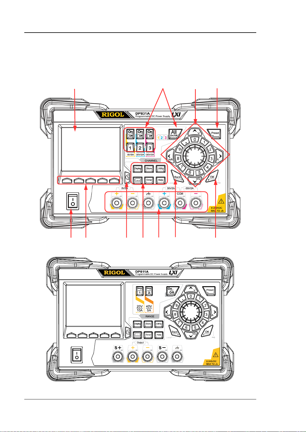
Front Panel
In this section, DP831A (as shown in Figure 1-3) is taken as a n example t o intr oduce
the front panel of DP800A series. The differences between different models are
introduced separately.
1 2 3 4
11 10 9 8 7 6 5
Figure 1-3 DP831A Front Panel
Figure 1-4 DP811A F ront Panel
1-4 DP800A User’s Guide
Page 23
Chapter 1 Quick Start RIGOL
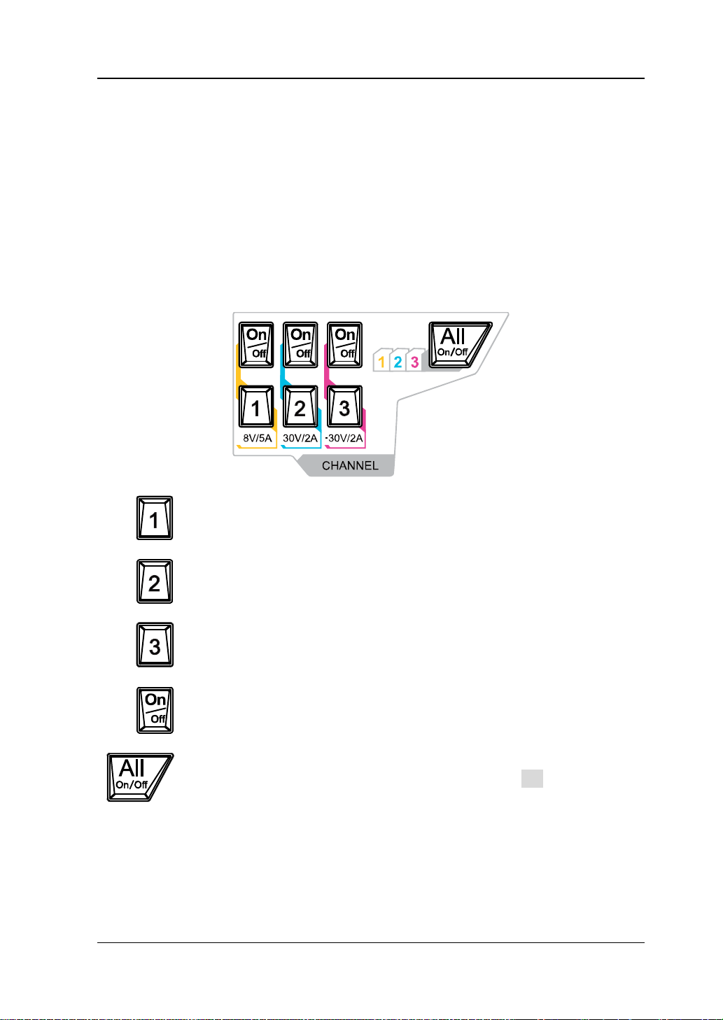
Press this key to select CH1 and set the parameters of this channel,
Press this key and the prompt message asking whether to enable the
1. LCD
3.5 inches TFT display. It is used to display the system parameter setting,
system output state, menu items, prompt messages, etc.
2. Channel (Range) Selection and Output Switch
For the multi-channel model, the function of this part is channel selection and
output switch. For the single channel model (DP811A), the function of this part
is range selection and output switch.
Multi-channel Model (take DP831A as the example):
such as voltage, current and overvoltage/overcurrent protection.
Press this key to select CH2 and set the parameters of this channel,
such as voltage, current and overvoltage/overcurrent protection.
Press this key to select CH3 and set the parameters of this channel,
such as voltage, current and overvoltage/overcurrent protection.
Press this key to enable or disable the output of the co rrespo ndi ng
channel.
outputs of all the channels will be displayed. Press OK to enable the
outputs of all the channels. Pressing this key again will disable the
outputs of all the channels.
DP800A User’s Guide 1-5
Page 24
RIGOL Chapter 1 Quick Start
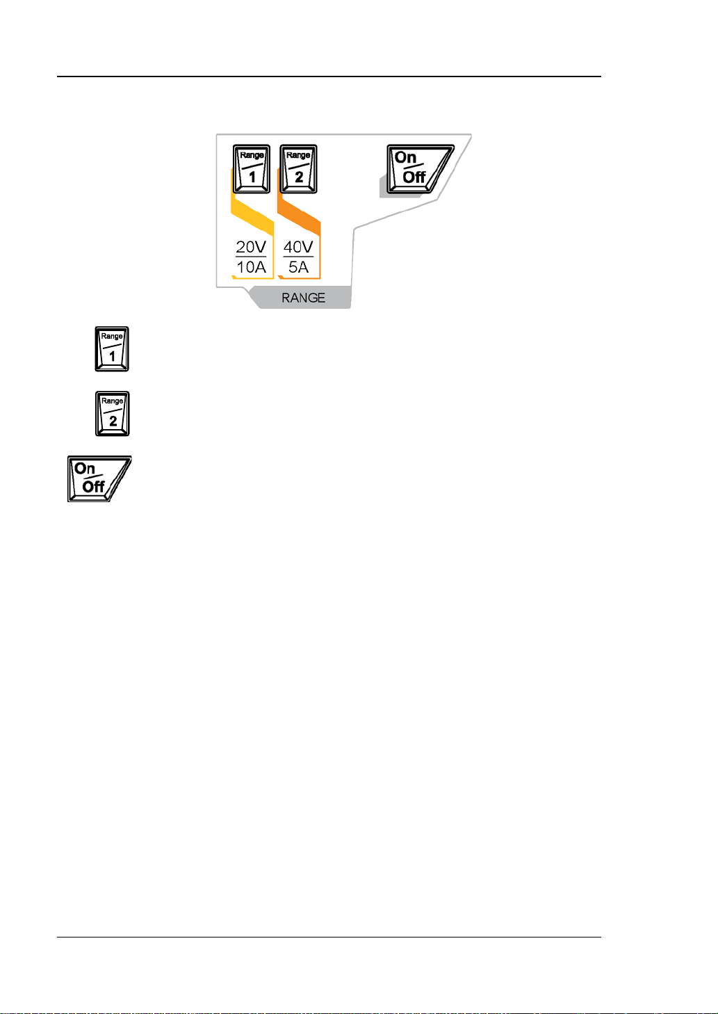
Press this key to select the 40V/5A range. Users can set the parameters
Single Channel Model (DP811A):
Press this key to select the 20V/10A range. Users can set the
parameters of the channel, such as voltage, current and
overvoltage/overcurrent protect i on.
of the channel, such as voltage, current and overvoltage/overcurrent
protection.
Press this key to enable or disable the output of the channel.
1-6 DP800A User’s Guide
Page 25

Chapter 1 Quick Start RIGOL
3. Parameter In p ut Area
The parameter input area is as shown in the figure below. This area includes the
direction keys (unit selection keys), numeric keyboard and knob.
(1) Direction keys and unit selection keys
Direction keys: move the cursor. When setting parameters, use the
up/down direction key to increase or reduce the value at the cursor.
Unit selection keys: whe n usi ng the nume ric ke yboa rd t o i nput par ameter s,
the keys are used to select the voltage units (V and mV) and the current
units (A and mA).
(2) Numeric Keyboard
Ring-type numeric keyboard: include numbers 0-9 and the decimal point.
Press the corresponding key to directly input the number or decimal point.
(3) Knob
When setting parameters, rotate the knob to increase or reduce the value
at the cursor.
When browsing the setting objects (timer parameters, delay parameters,
filename input, etc.), rotate the knob to quickly move the cursor.
DP800A User’s Guide 1-7
Page 26
RIGOL Chapter 1 Quick Start
keys.
Delete the character currently before the cursor.
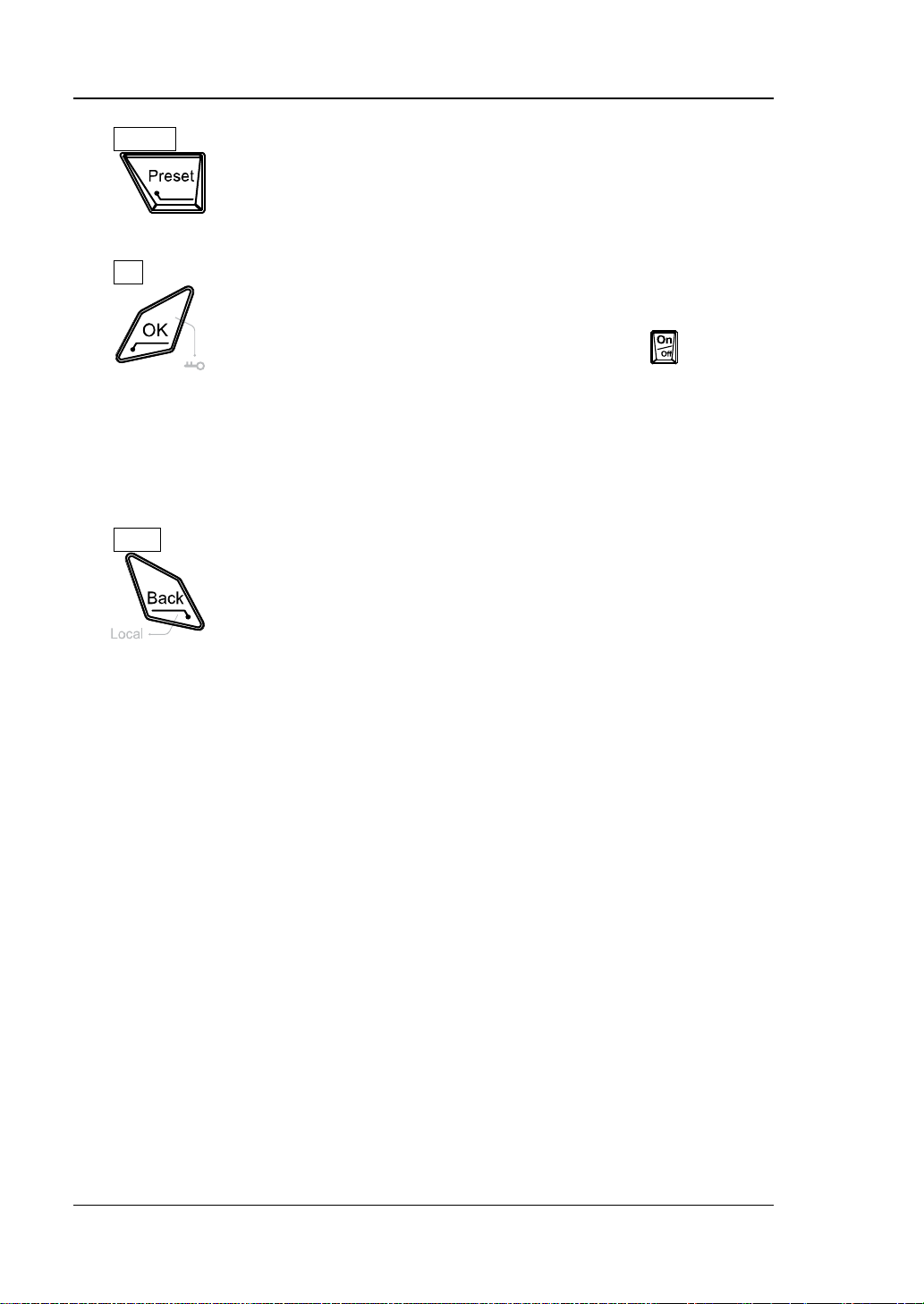
4. Preset
Restore all the settings of the instrument to default values or
recall the user-defined channel voltage/current configuration.
5. OK
Confirm the parameter setting.
Press and hold this key to lock the front pane l keys; at this point,
6. Back
the front panel keys (except the output on/off key
of each
channel) are not available. When the keyboard lock password is
disabled, p ress an d h old t his k e y a gain t o u nlock the f ront panel
keys. When the keyboard lock password is enabled, you need to
input the correct password (2012) to unlock the front panel
When the instrument is in remote mode, p ress this k ey to return
to local mode.
1-8 DP800A User’s Guide
Page 27
Chapter 1 Quick Start RIGOL
(1)
(3)
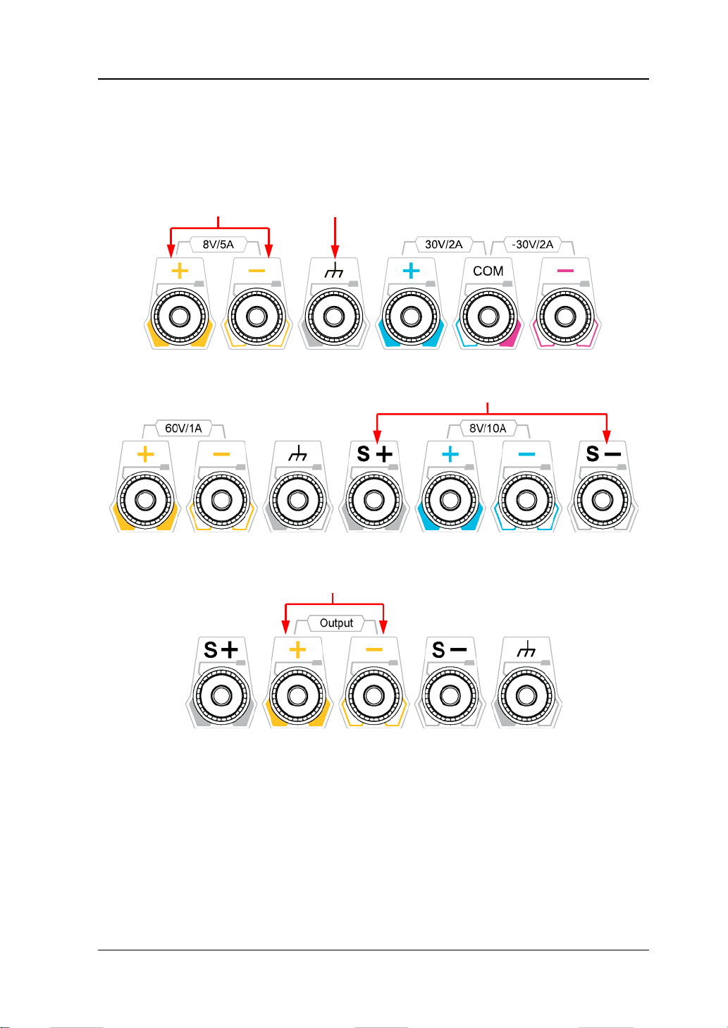
7. Output Terminals
For DP800A series, the output terminals of different models are not exactly the
same.
DP831A:
(1) (2)
DP821A:
DP811A:
(1) Channel output terminals: used to output the voltage and current of the
channel.
(2) Ground terminal: this terminal is connected to the instrument chassis and
ground wire (power cord ground terminal) and is in grounded state.
(3) Sense terminals: used to sense the actual voltage at the load to
compensate the voltage drop caused by the load leads.
DP800A User’s Guide 1-9
Page 28

RIGOL Chapter 1 Quick Start
A
Connection methods of the output terminal:
B
Method 1:
Connect the test lead to A of the output terminal.
Method 2:
Rotate the outer nut of the output terminal counterclockwise and connect the
test lead to B of the output terminal; then, rotate the outer nut of the output
terminal clockwise. This connection method can eliminate the error caused by
the resistance of the output terminal.
Note: Connect the posit ive terminal of the test lea d wi th the (+) terminal of the
channel output and connect the negative terminal of the test lead with the (-)
terminal of the channel output.
1-10 DP800A User’s Guide
Page 29

Chapter 1 Quick Start RIGOL
Press this key to enter the display parameter setting interface.
Press this key to enter the advanced function setting interface.
Press this key to open the built-in help system and press the
8. Function Menu Area
Users can set the brightness, contrast, RGB luminance and display
mode. Besides, you can also define the start-up interface.
Press this key to enter the file store and recall interface. You can
save, read, delete, copy and paste files. The file types available for
storage include state file, record file, timer file, delay file and
bitmap file. The instrument supports internal and external storage
and recall.
Press this key to enter the system utility function setting interface.
Users can set the remote interface parameters, system parameters
and print parameters. Besides, users can also calibrate the
instrument, view system information and define the recall
configuration of Preset.
Users can set the recorder, analyzer, monitor and trigger
parameters.
Press this key to enter the timer and delayer interface. Users can
set the timer and delayer parameters as well as turn on or off the
timer and delayer.
desired key to get the corresponding help information. For the
detailed introductions, refer to “
System”.
To Use the Built-in Help
DP800A User’s Guide 1-11
Page 30
RIGOL Chapter 1 Quick Start
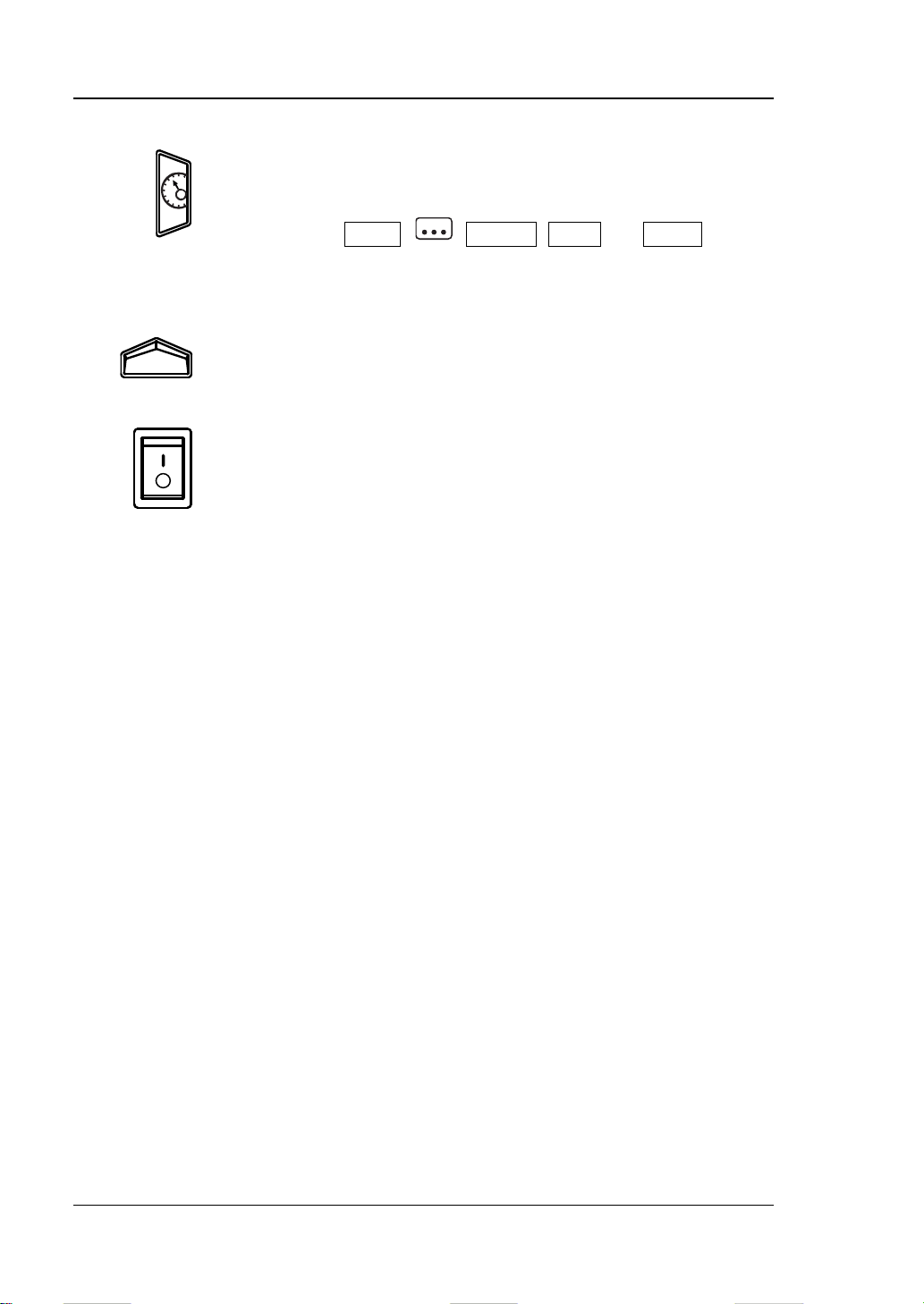
9. Display Mod e Switch/Return to the Main Interface
Switch between the current display mode and dial display mode.
Besides, when the instrument is in a function interface (any
interface under Timer,
, Display, Store and Utility),
press this key to exit the f unction interf ace and return to the main
interface.
10. Menu Keys
The menu keys correspond to the menus above them. Pres s a n y
menu key to selec t the corresponding menu.
11. Power Switch Key
Turn on or off the instrument.
1-12 DP800A User’s Guide
Page 31

Chapter 1 Quick Start RIGOL
11
10 9 8
1 2 3 4 5 6
Rear Panel
In this section, DP831A (as shown in Figure 1-5 and Table 1-1) is taken as an
example to introduce the rear panel of DP800A series.
7
Figure 1-5 DP831A Rear Panel
Figure 1-6 DP811A Rear Panel
DP800A User’s Guide 1-13
Page 32

RIGOL Chapter 1 Quick Start
No.
Name
Explanation
1
LAN Interf ace
Connect to the local network via the RJ45 interface
Connect the instrument (as “slave” device) to
5
RS232 Interface
Serial communication interface
Select the specification of the input voltage (100, 115
7
Power Socket
AC power input interface
Only DP811A provides this interface which has the
Table 1-1 DP800A rear panel explanation
2 USB DEVICE
external USB device (such as PC)
Connect the instrument (a s “host” device) to external
3 USB HOST
USB device (such as USB storage device);
extend a GPIB interface for the power supply using
the USB-GPIB interface converter (option)
4 Digital I/O Digital I/O interface
6 Voltage Selector
or 230; please refer to Table 1-2)
The fuse specification is related to the instrument
8 Fuse
model and the actual input voltage (please refer to
the “Input Power Requir ements” at the rear panel or
Table 1-3)
9 Fan
10
Input Power
Requirements
11 Output Interface
Corresponding relations of the AC input power
frequency, voltage and fuse specification
same function as that of the “Output Termin als” at
the front panel
Note: The “Output Terminals” at the front panel and the “Output Interface” at the
rear panel cannot o utput at the same time. Only one of the two ways can be selected
to output at any one time (the “Output Terminals” at the front panel has higher
accuracy).
1-14 DP800A User’s Guide
Page 33

Chapter 1 Quick Start RIGOL
AC Input Power
Voltage Sele ctor Setting
100Vac±10%, 50Hz to 60Hz
100
115Vac±10%, 50Hz to 60Hz
115
230Vac±10% (250Vac maximum ), 50Hz to 60Hz
230
WARNING
To Connect to Power
DP800A series power supply supports various AC power supply inputs. The voltage
selector setting at the rear panel differs when the input power connected is different,
as shown in the table below.
Table 1-2 AC input power specif ications (voltage selector settings)
Please connect the power following the steps below.
1. Check the input power
Make sure that the AC power to be connected to the instrument fulfills the
requirements in Table 1-2.
2. Check the voltage selector at the rear panel
Make sure that the v oltage selector setting (110, 115 or 230 ) at the rear panel of
the instrument matches the actual input voltage (for the matching relations
refer to Table 1-2).
3. Check the fuse
When the instrument leaves factory, a specified fuse is installed. Please make
sure that the fuse matches the actual input voltage according to the “Input
Power R e quirements” at the rear panel of the instrument or Table 1-3.
4. Connect the AC power
Connect the instrument to AC power supply using the power cord provided in
the accessories.
To avoid electric shock, make sure that the instrument is correctly
grounded.
DP800A User’s Guide 1-15
Page 34

RIGOL Chapter 1 Quick Start
Tip
Input Voltage
Fuse Specification
DP831A/DP821A
DP832A/DP811A
100Vac/115Vac
T6.3A
230Vac
T3.15A
Power-on Inspection
Press the power switch at the front panel, the instrument starts and executes
self-test. If the instrument passes the self-test, the welcome interface will be
displayed; otherwise, the corresponding self-test failure information (including the
top board, bottom board, fan an d temperature) will be di s pl ayed.
When powering on the instrument after powering off it, make sure that the time
interval between the two operations is greater than 5s.
To Replace the Fuse
The fuse specification is related to the inst rument model and actual input v oltage, as
shown in the table below. You can also refer to the “Input Power Requirements” at
the rear panel of the instrument.
Table 1-3 Fuse specifications
100Vac/115Vac T5A
230Vac T2.5A
To replace the fuse, follow the steps below.
1. Turn off the instrument and remove the power cord.
2. Insert a small strai ght screwdrive r into the slot at the power socket an d prize out
the fuse seat gently.
Fuse Seat
Fuse
1-16 DP800A User’s Guide
Page 35

Chapter 1 Quick Start RIGOL
WARNING
3. If needed, manually adjust the power voltage selector to the voltage scale
(please refer to Table 1-2) that matches the actual input voltage.
4. Take out the fuse and replace it with a specified one (please refer to Table 1-3).
5. Re-insert the fuse seat into the power socket (pay attention to the direction).
To avoid personal injuries, cut off the power supply before replacing the
fuse; to avoid electric shock or fire, select the power supply specification
that matches the actual input voltage and replace a fuse corresponding to
this specification before connecting to power.
DP800A User’s Guide 1-17
Page 36

RIGOL Chapter 1 Quick Start
8 9 10 11
User Interface
DP800A series power supply supports various display modes. The default is normal
display mode.
DP831A/DP832A: normal, waveform, dial, classic
DP821A/DP811A: normal, waveform, dial
Press Display Disp Mode to select the desired display mode. In this section,
DP831A is taken as an example to introduce the user interface layout under the
normal display mode (as shown in
1
2
3
4
5
6
7
Figure 1-7 DP831A Use r Interface (Normal)
Figure 1-7 and Table 1-4 on the next page).
1-18 DP800A User’s Guide
Page 37

Chapter 1 Quick Start RIGOL
No.
Explanation
1
Voltage and current setting values
2
Overvoltag e and over current protection setting values
9
Channel output status
10
Channel output voltage/current (channel currently selected)
11
Status bar. Display the system status labels.
Tip
when the current displa y mode i s “Normal”, “Waveform”
Table 1-4 DP800A user interface explanation
3 Actual output voltage
4 Actual output current
5 Actual output power
6 Channel output mode
7 Menu bar
8 Channel number
: over-temperature protection is enabled
: the front panel is locked.
: the network is connected.
: USB device is recognized.
: the beeper is enabled.
: the beeper is disabled.
: the instrument is in remote mode.
For DP831A/DP83 2A,
or “Classic”, press at the front panel to quickly switch between the current
display mode and dial display mode.
For DP821A/DP811 A, when the cu r rent displa y mo de is “Normal” or
“Waveform”, press
at the front panel to quickly switch between the current
display mode and dial display mode.
DP800A User’s Guide 1-19
Page 38

RIGOL Chapter 1 Quick Start
To Use the Built-in Help System
The built-in help s ystem provides help inf ormation f or any fr ont panel ke y (except the
parameter input area) and menu keys for users to quickly obtain the function
prompts of the function keys or menus.
Obtain the help information of any key or menu key
Press Help to illuminate it an d press the desired key or menu key to get the
corresponding help information; at the same time, the backlight of Help goes off.
Press to exit the help system.
Built-in help interface
Press Help to illuminate it and press Help again to open the built-in help interface.
Use the up/d own directi o n ke y or knob to select the desired help topic and press
View to view the corresponding help information.
The help topics include:
1. View the last displayed message.
2. View error queue of the remote commands .
3. Get the help information of a key.
4. Storage m anagement.
5. Abbreviations list.
6. Series-parallel Help.
7. Get technical support from RIGOL.
1-20 DP800A User’s Guide
Page 39

Chapter 2 Front Panel Operations RIGOL
Chapter 2 Front Panel Operations
The contents of this chapter are as follows:
Constant Voltage Output
Constant Current Output
Power Supply Series and Parallel Connections
Track Function
Sense Working Mode
Timer and Delayer
Advanced Functions
Display Setting
Store and Recall
Utility
DP800A User’s Guide 2-1
Page 40

RIGOL Chapter 2 Front Panel Operations
CAUTION
Constant Voltage Output
DP800A series power supply provides three output modes: constant voltage output
(CV), constant current output (CC) and critical mode (UR). In CV mode, the output
voltage equals the volta ge set ting v alue a nd the output current is deter mined by th e
load; in CC mode, the output current equals the current s etting v alue a nd the outpu t
voltage is determined by the load; UR is the critical mode between CV and CC. This
section introduces the operation method in constant v olt age outp ut mo de.
Operation Method:
1. Connect the channel output terminals
As shown in the figure below, connect the load to the output terminals of the
corresponding channel at the front panel.
To avoid damag ing the instrument or the device connected to it, pay
attention to the polarity when connecting.
2. Turn on the power switch to start the instrumen t.
3. Select the channel
Select the proper output channel according to the desired output volta ge. Pre ss
the corresponding channel selection key; at this point, this channel, its channel
number and output state are high-lighted on the screen.
4. Set the voltage
Method 1
Press Voltage and use the left/right direction key to move the cursor; then,
rotate the knob to quickly set the v oltage and t he default unit is V. After selecting
the digit to be set, you can also use the up/down direction key to modify the
value of the corresponding digit and the default unit is V.
Method 2
Press Voltage and use the numeric keyboard to directly input the desired
voltage value; press V or mV or the unit selection key ( or ) to select
the desired unit. Besides, you can also press OK to select the default unit (V).
2-2 DP800A User’s Guide
Page 41

Chapter 2 Front Panel Operations RIGOL
During the input, you can press Back to delete the character currently before
the cursor or press Cancel to cancel the input.
Method 3
When Current is selected, you can use the numeric keyboard to directly input
the desired voltage value and press the unit selection key (
or ) to
select the desired voltage unit. During the input, you can press Back to delete
the character currently before the cursor or press Cancel to cancel the input.
5. Set the current
Method 1
Press Current and use the left/r ight direction key to move the cursor; then,
rotate the knob to quickly set the current and the default unit is A. After
selecting the digit to be set, you can also use the up/down direction key to
modify the value of the corresponding digit and the default unit is A.
Method 2
Press Current and use the numeric keyboard to directly input the desired
current value and press A or mA or the unit selection key ( or ) to select
the desired unit. Besides, you can also press OK to select the default unit (A).
During the input, you can press Back to delete the character currently before
the cursor or press Cancel to cancel the input.
Method 3
When Voltage is selected, you can use the numeric keyboard to directly input
the desired current value and press the unit selection key (
or ) to select
the desired unit. During the input, you can press Back to delete the character
currently before the cursor or press Cancel to cancel the input.
6. Set the overcurrent protection
Press OCP to set a p roper overcurrent protection val ue (for the setting method,
refer to “
Set the current”). Then, enable the overcurrent protection function
(you can enable or disable the OCP function by pressing OCP) and the output
will be turned off automatically when the actual output current is greater than
the overcurrent protection value.
7. Turn on the output
Turn on the outp ut o f t he corresponding channel and the actual output voltage ,
output current, output power as well as the output mode (CV) are high-lighted
in the user interface.
DP800A User’s Guide 2-3
Page 42

RIGOL Chapter 2 Front Panel Operations
WARNING
CAUTION
To avoid elect ric shock, please turn on the output switch after the
output terminals are correctly connected.
When the fan stops, the channel switch can not be turned on;
otherwise, “The fan stops, stop the output!” will be displayed.
8. Check the output mode
In constant voltage output mode, the output mode displayed should be “CV”; if
“CC” is displayed, you can increase the current setting value properly and the
power supply will switch to CV mode automatically.
Besides, DP811A also provides out put interfa ce at the rear panel for constant voltage
output. As shown in the figure below, the load is connected to the output interface at
the rear panel for constant via a connecting terminal.
Rear Output Interface
Connecting Terminal
Connection Steps:
1. Connect the load to the corresponding position of the connecting terminal
correctly according to the figure ab ove. Note the polarity when connecting.
2. Insert the connecting terminal to the output interface at the rear panel of the
instrument correctly according to the f i gure above. Note the corresponding
relationship between the connecting terminal and the output interface when
inserting.
2-4 DP800A User’s Guide
Page 43

Chapter 2 Front Panel Operations RIGOL
Tip
Note: The output terminals at the front panel and the output interface at the rear
panel cannot output at the same time. You can only select one of the two ways to
output at any one time (the f o rmer has higher output accuracy than the latter).
In CV output mode, when the load current is greater than the current setting
value, the power supply will swit ch to CC output mode aut omatically. At this point,
the output current equals the current set ting value a nd the output v oltage redu ces
proportionally.
DP800A User’s Guide 2-5
Page 44

RIGOL Chapter 2 Front Panel Operations
Warning
Constant Current Output
In constant current output mode, the output current equals the current set ting v alue
and the output voltage is determined by the load. This section introduces the
operation method in constant current output mo de.
Operation Method:
1. Connect the channel output terminals
Connect the load with the channel output terminals of the corresponding
channel at the front panel by referring to “Connect the channel output
terminals” in “Constant Voltage Output”.
2. Turn on the power switch to start the instrument.
3. Select the channel
Select the proper output channel accordi ng t o the desired output current. Pre ss
the corresponding channel selection key; at this point, this channel, its channel
number and output state are high-lighted in the center of the screen.
4. Set the voltage
Press Voltage to set the desired voltage according to “Set the voltage” in
“Constant Voltage Out put”.
5. Set the current
Press Current to set the desired current according to “Set the current” in
“Constant Voltage Output”.
6. Set the overvoltage protection
Press OVP to set the proper overvoltage protection value (for the setting
method, refer to “
enable the overvoltage protection function (you can enable or disable the OVP
function by pressing OVP) and the output will be tu rned off auto maticall y when
the actual output voltage is greater than the overvoltage protection value.
7. Turn on the output
Turn on the outp ut o f t he corresponding channel and the actual output voltage ,
output current, output power as well as the output mode (CC) are high-lighted
in the user interface.
Set the voltage” in “Constant Voltage Output”). Then,
2-6 DP800A User’s Guide
To avoid electric shock, please turn on the output switch after the
output terminals are correctly connected.
Page 45

Chapter 2 Front Panel Operations RIGOL
CAUTION
Tip
value, the power supply will swit ch to CV output mode automati cally. At this point,
When the fan stops, the channel switch can not be turned on;
otherwise, “The fan stops, stop the output!” will be displayed.
8. Check the output mode
In constant current output mode, the output mode displayed should be “CC”; if
“CV” is displayed, you can increase the voltage setting value properly and the
power supply will switch to CC mode automatically.
Besides, DP811A also provides output interface at the rear panel for constant current
output. For the detailed connection method, please refer to the introduction in
“Constant Voltage Output”.
Note: The output terminals at the front panel and the output interface at the rear
panel cannot output at the same time. You can only select one of the two ways to
output at any one time (the former has higher output accuracy than the latter).
In CC output mode, when the load voltage is greater than the voltage setting
the output voltage equals the volta ge setting v alue a nd the output current reduces
proportionally.
DP800A User’s Guide 2-7
Page 46

RIGOL Chapter 2 Front Panel Operations
Power Supply
Channel #1
-
+
Power Supply
Channel #2
-
+
V
1
V
2
V
L
R
Load
-
+
VL=V1+V
2
Power Supply Series and Parallel Connections
Higher voltages can be pro vided when t wo or more i nsulated channels (the ch annels
can be from a single power supply or multiple power supplies) are connected in
series. Higher currents can be provided when two or more insulated channels (the
channels can be from a single power supply or multiple power supplies) are
connected in parallel.
Note:
1. Only insulated channels can be connected in series or in parallel.
For a single power supply:
Any two channels of DP831A can be connected in series; CH1 and CH2/CH3
can be connected in parallel, but CH2 and CH3 cannot be connected parallel.
CH1 and CH2/CH3 of DP832A can be connected in series or in parallel, but
CH2 and CH3 cannot be connected in series or parallel. The two channels of
DP821A can be connected in series or in parallel.
Channels (insulate d channels) of different power supplies can be connecte d
in series or in parallel.
2. In power series and parallel connections, the settings of the corresponding
parameters must comply with the safety requirements.
Power Supply Series Connection
Higher voltages can be provided by connecting power supplies in series. In this case,
the output voltage is the sum of the output voltages of all the channels. In power
supply series connection, you need to set the same current setting value and
overcurrent protection value for all the channels. Take the series connection of two
channels as an example; the connection method is as shown in the figure below.
Operation Procedures:
1. Connect the power supply and load as sh own in the figure above. Pay attention
2-8 DP800A User’s Guide
to the polarity when making connections.
Page 47

Chapter 2 Front Panel Operations RIGOL
Power Supply
Channel #1
-
+
Power Supply
Channel #2
-
+
I
1
I
L
R
Load
I
2
IL=I1+I
2
2. Set proper voltage, current and overcurrent protection value for each channel
(all the channels in series connection should be working in constant voltage
mode; you should set the same current set ting v alue s and the same overcurrent
protection values for all the channels) by referring to “Constant Voltage
Output”. Turn on the output of each channel.
Note: Make sure that all the channels in series connection are working in constant
voltage mode. If one of the channels is workin g i n constant current mode, the other
channels will enter critical state in which their outputs are unpredictable.
Power Supply Parallel Connection
High currents can be provided by c onnecting power supplies i n parallel. In t his case,
the output current is the sum of the output currents of all the channels. In power
supply parallel connection, you can set the parameters of each power supply. Ta ke
the parallel connection of two channels as an example; the connection method is as
shown in the figure below.
Operation Procedures:
1. Connect the power supply and load as sh own in the figure above. Pay attention
to the polarity when making connections.
2. Set proper parameters for each channel (all the channels can work in constan t
voltage or constant current mode) by referring to “Constant Voltage Output”
and “Constant Current Output”. Turn on the output of each channel.
Note: All the channels can work in constant voltage or constant current mode
according to the actual need of the load.
DP800A User’s Guide 2-9
Page 48

RIGOL Chapter 2 Front Panel Operations
Tip
Track Function
The track function is usually used to provide symmetric voltage for the operation
amplifier or other circuit. For DP800A series power supply, the specified channels of
the following models support the track function.
DP831A: CH2 and CH3;
DP832A: CH1 and CH2.
For channels that support the track function, you can set the tracking states of the
voltage setting value and output on/off state respectively according to your need.
To Enable the Track Functi on
Press Utility System Track Set Track to select “Independent” or
“Synchronous”.
Independent: for two channels (the channels should be of the same
instrument) that support the track function, the status of the track function of
the other channel will not be affected when the track function of a channel is
enabled or disabled.
Synchronous: for two channels (the channels should be of the same
instrument) that support the track function, the track function of the other
channel will be enabled or disabled at the same time when the track function of
a channel is enabled or disabled.
When “Independent” is selected, users can enable or disable the track
function of a single channel freely.
When “Synchronous” is selected, users can quickly e nable o r disable the tr ack
functions of the two channels at the same time.
For channels (the channels should be of the same in strument) th at support th e tra ck
function, the tracking status of the channel voltage setting value is related to the
number of channels of which the track functions are enabled.
If only the track functi on of a single channel is en abled, the voltage set ting value
of the other channel will change accordingly when the voltage setting value of
this channel is modified. At this point, t he voltage setting val ue of the channel of
which the track function is not enabled cannot be set and can only change with
that of the channel of which the track function is enabled.
If the track functions of the two channels are both enabled, the voltage setting
value of the other channel will change accordingly when the voltage setting
value of a channe l is modified. At this point, the volta ge setting v alues of both of
2-10 DP800A User’s Guide
Page 49

Chapter 2 Front Panel Operations RIGOL
Tip
the two channels can be set.
The track function only tracks the voltage setting value and the actual output
voltage will not be affected.
You can perform the following operations according to your need.
1. Only enable the track function of a single channel and track the
voltage setting value
The operation pro cedures are as follows (in this exa mple, only the t rack fun ction
of CH2 of DP831A is enable d).
Select the “Independent” trackin g m ode
Press Utility System Track Set Track to select “Independent”.
Enable the track functi on of CH2
Select CH2 and press Track to select “On”. At t his point, the track f uncti on
of CH2 is enabled and the tracking status icon
is displayed in t he CH2
area in the user interface.
Disable the track function of CH3 (ignore this step if the track function of
CH3 is currently disabled)
Select CH3 and press Track to select “Off”. At this point, the track function
of CH3 is disabled and the tracking status icon
in the CH3 area in the
user interface disappears.
Track the voltage setting value
Select CH2, press Voltage and set the desired voltage. At this point, the
voltage of CH3 changes accordingly. For example, set the volta ge of CH2 to
+5V; the voltage of CH3 will change to -5V automatically.
Note: At this point, the v oltage se tt ing v alue of CH3 cannot be set and can
only change with that of CH2.
2. Enable the track functions of both of the two channels and track the
voltage setting value
First, you can enable the tr ack functions of the t wo channels (take DP831A as an
example) using any of the following methods.
Method 1
Select the “Synchronous” tracking mode
Press Utility System Track Set Track to select “Synchronous”.
DP800A User’s Guide 2-11
Page 50

RIGOL Chapter 2 Front Panel Operations
Enable the track functions of CH2 and CH3 at the same time
Select CH2 or CH3, press Track and select “On”. At this point, the track
functions of CH2 and CH3 are both enabled. The tracking status icons
and
are displayed in the CH2 and C H3 areas in the user interface
respectively.
Method 2
Select the “Independent” trackin g m ode
Press Utility System Track Set Track to select “Independent”.
Enable the track functions of CH2 and CH3
Select CH2 and press Track to select “On”. At t his point, the track function
of CH2 is enabled and the tracking status icon
is displayed in t he CH2
area in the user interface. Use the same method to enable the track
function of CH3.
Then, select CH2 or CH3 and press Voltage and set the desired voltage. At this
point, the voltage setting value of the other channel changes accordingly. For
example, set the voltage of CH2 to +5V; the voltage of CH3 will change to -5V
automatically.
Note: At this point, both of the voltage setting values of CH2 and CH3 can be
set.
2-12 DP800A User’s Guide
Page 51

Chapter 2 Front Panel Operations RIGOL
To Track the On/Off Status o f th e Channel Output
Press Utility System Track Set On/Off to select “Enable” or “Disable”.
Disable: the output status of the other channel will not be affected when the
output of a channel is turned on or off.
Enable: for channels (the channels should be of the same instrument) that
support the track function, the tra cking status of the on/off status of the channel
output is related to the number of channels of which the track functions are
enabled.
If only the track function of a s ingle channel is e nabled (please ref e r to “To
Enable the Track Function”), the output of the other channel will be
turned on or off a t t he same time when the o utput of this channel is turne d
on or off. At this point, the output status of the channel of which the track
function is not enabled cannot be set and can only change with that of the
channel of which the track function is enabled.
If the track functions of the two channels are both enabled (please ref er to
“To Enable the Track Function”), the output of the other channel will be
turned on or off at the same time when the output of a channel is turned on
or off. At this point, the output status of both of the two channels can be
set.
DP800A User’s Guide 2-13
Page 52

RIGOL Chapter 2 Front Panel Operations
Equivalent Resistance
Sense Working Mode
When the output current of the power supply is high, the voltage drop on the load
lead cannot be ignored. To make sure that the load can acquire accurate voltage
drop, CH2 of DP821A and DP811A (which can provide 10 A output current) provide
the Sense (remote sense) working mode. In this mode, the voltage is sensed at the
load rather than at the power supply’s output terminals. It allows the system to
automatically compensate the voltage drop in the load leads so as to ensure the
specified output value can be consistent with the voltage received by the load.
The Sense connection method at the front panel is as shown in the figure below.
Sense Leads
Load Leads
Sense Leads
Equivalent Resistance
Load Leads
Operation Steps:
1. Connect the channel output terminals and Sense terminals at the front panel of
the instrument to both ends of the load, as shown in the figure a bove. Pay
attention to the polarity when making connections.
2. For DP821A, after selecting CH2 (8V /10A), press Sense to enable the Sense
function.
For DP811A, after selecting the desire d range , press Sense to enable the Sense
function.
Tip
When outputting a high current, use as short as possible and twisted load
leads in order to obtain the best output characteristi cs.
Please use a twisted-pair as the Sense lead as possible as you can and the
leads should not be twisted with the load leads.
2-14 DP800A User’s Guide
Page 53

Chapter 2 Front Panel Operations RIGOL
Rear Output Interface
Besides, DP811A also provides output interface at the rear panel for Sense wo rk
mode. The Sense connection method at the rear panel is shown in the figure below.
Connecting Terminal
Operation Steps:
1. Connect the load to the corresponding position of the connecting terminal
correctly ac cording to the figure above. Note the polarity when connecting.
2. Insert the connecting terminal to the output interface at the rear panel of the
instrument correctly. N ote the corresponding relationship between the
connecting terminal and the output interface when inserting.
3. After the desired range is selected, press Sense to enable the Sense function.
Note: The output terminals at the front panel and the output interface at the rear
panel cannot work in Sense mo de at the same time. You can only select one of the
two ways to enable the Se nse function at any one time (the fo rmer has higher output
accuracy than the latter).
DP800A User’s Guide 2-15
Page 54

RIGOL Chapter 2 Front Panel Operations
Timer and Delayer
DP800A provide s the timer and delayer functions.
When the timer is enabled, the instrument outputs the preset voltage and current
values (at most 2048 groups). Users can set the number of output groups of the
timer as well as the voltage, current and timing time of each group. Besides, the
instrument provides various built-in output templets and users c an select and edit
the templet as well as create timer pa rameters based on the templet. The instrument
will output according to the parameters currently created.
When the delayer is enabled, the instrument enables or disables the output
according to the preset state and delay time (at most 2048 groups). Users can set
the number of output groups of the delayer as well as the state and delay time of
each group.
Users can store the edited timer parameters (timer file, with the suffix “*.RTF”) and
delay parameters (delay file, with the suffix “*.RDF”) in internal or external memory
and recall them when required.
Press Timer (the backlight turns on) to open the timer and delayer interface (as
shown in the figure below). The function of each menu key is as follows.
1. Timer Set: open the timer parameter setting interface and set the timer
parameters;
2. Timer: turn on or off the timer;
3. Delay Set: open the delay parameter setting interface and set the delay
parameters;
4. Delayer: turn on or off the delayer.
Figure 2-1 Timer and Delayer Interface
2-16 DP800A User’s Guide
Page 55

Chapter 2 Front Panel Operations RIGOL
r function are mutually exclusive. When the timer is
Timer Parameter Preview Channel Currently Selected Timer Parameter List
Tip
The timer function and dela y e
enabled, Delayer is gra yed out and disabled; when the delayer is en abled, Timer
is grayed out and disabled.
To Set the Timer Parameters
Press Timer Timer Set to enter the timer parameter setting interface a s shown
in the figure below. The channel currently selected is displayed in the status bar.
Press the channel selection keys at the front panel to switch the channel currently
selected. This interface provides timer para meter preview; users can view the v alues
on the current page of the timer parameter list (the horizontal axis represents time
and the vertical axis represents voltage and current).
Figure 2-2 Timer Parameter Setting Interface
You can set the timer parameters in the timer parameter setting interface following
the steps below.
1. To Set the Number of Output Groups
2. To Set the Number of Cycles
3. To Set the End State
4. To Edit the Timer Parameters
5. To Save and Read the Timer F ile
DP800A User’s Guide 2-17
Page 56

Tip
RIGOL Chapter 2 Front Panel Operations
To Set the Number o f Output Groups
The number of output groups is defined as the number of groups of preset voltage
and current values that the power supply outputs in each cycle. Press Groups and
use the numeric keyboard or the left/right direction key and knob to input the desired
value. The range is from 1 to 2048.
To Set the Number of Cycles
The number of cycles is defined as the number of times that the i nstrument performs
timing output according to the preset voltage and current. Press Cycles to set the
number of cycles to “Infinite” or use the numeric keyboard or the left/right direction
key and knob to input the desired value. The range is fr om 1 to 99999.
The total number of groups in timing output = the number of output
groups*the number of cycles
The power supply will terminate the timer function when the total number of
groups of output s is finished. At this point, the state of the power supply
depends on the setting in “To Set the End State”.
To Set the End State
The end state refers to the state of the instrument after it finishes outputting the
total number of gr oups of voltage an d cur rent v alues when t he num be r of cy cles is a
specif ied value. Press End State to select “Outp Off” or “Last ”.
Outp Off: the instrument turns off the output automatically after finishing the
output.
Last: the instrument stops at the output state of the last group after finishing
the output.
Note: When the number of cycles is set to “Infinite”, the end state is invalid.
To Edit the Timer Parameters
You can edit the timer parameters manually or using the built-in templet.
To Edit the Timer Parameters Manually
You need to set P groups (No.0 to No.(P-1)) of timer parameters; wherein, P is the
number of output groups currently set. On ly 6 groups of pa rameters can be
displayed on each page of the timer para meter list an d you can press
or to
2-18 DP800A User’s Guide
Page 57

Chapter 2 Front Panel Operations RIGOL
view and set the parameters of the other groups. This interface provides timer
parameter preview; users can view the values on the current page of the timer
parameter list (the horizontal axis represents time and the vertical axis represents
voltage and current).
1. Press Parameter and use the numeric keyboard, the left/right direction key or
the knob to select the specified number (No.) in the timer parameter list.
2. Use the u p/down direct ion ke y to select the voltage (V), current (C) and time (s)
of the current group respe ctively an d use the n umeri c ke yboard or the left/right
direction key and knob to input the desired value.
3. Use the same method to set the parameters of the other groups.
To Edit the Timer Parameters using Templet
The instrument provides various built-in output templets. Users can select the
desired templet, edit the timer parameters using the templet and create waveform.
The instrument will output according to the waveform currently created.
Press Templet to open the templet editing menu. You can edit the timer parameters
according to the steps below.
1. Select the editing object
2. Select the templet
3. Edit the timer parameters
4. Construct the output waveform
1. Select the editing object
Press Edit Obj to select “Voltage” or “Current”.
Voltage: when it is selected, the interface displays the voltage preview and
you can set all the gr oups t o output a fixed current. Press Current and use
the numeric keyboard or the left/right directio n k ey and knob to set the
current value.
Current: when it is selected, the interface displays the current preview and
you can set all t he gr oups to output a fixed voltage. Press Voltage and use
the numeric keyboard or the left/right directio n k ey and knob to set the
voltage value.
2. Select the templet
Press Type to select the desired templet, including Sine, Pulse, Ramp, Stair Up,
Stair Dn, StairUpDn, Exp Rise and Exp Fall.
DP800A User’s Guide 2-19
Page 58

RIGOL Chapter 2 Front Panel Operations
T
t
Tip
Sine
The Sine waveform is as shown in the figure below. The instrument
determines the Sine amplitude according to the maximum and minimum
currently set and determines the Sine pe ri od accordi ng to the total number
of points (denoted by P) and the time interval currently set, thus
determining the Sine w av eform. When creating par ameters, the instrument
draws P values from the preset Sine waveform according to the current
time interval.
T
Pulse
The Pulse waveform is a s shown in the figure below. The timer parameters
created from Pulse waveform only contain two gr oups of data.
The f ir st group: the amplitude (voltage or current) is determined by the
high level set; the time equals the pulse width (t) currently set.
The second group: the amplitude (voltage or current) is deter mined by the
low level set; the t ime equals the period currently set minus the pulse w idth
currently set (T-t).
When Pulse is selected, if you w ant to output more than 2 groups of timer
parameters, you can output the timer parameters created from the Pulse
templet repeatedly by increasing the number of cycles.
2-20 DP800A User’s Guide
Page 59

Chapter 2 Front Panel Operations RIGOL
T
t
Symmetry=t/T*100%
Ramp
The Ramp waveform is as shown in the figure below. The instrument
determines the amplitude of the Ramp according to the maximum and
minimum currently set, determines the period according to the total
number of points (deno t ed by P) and the time interval currently set and
determines the Ramp waveform according to the symmetry (denoted by
Sym) currently set. When creating parameters, the instrument draws
[1]
int(P*Sym)
values from the rising edge of the preset Ramp waveform at
the same time interval and draws P-int(P*Sym) values from the falling
edge of the preset Ramp waveform at the same time interval. The timing
time is determined by the time interval currently set.
[1]
Note
: int(P*Sym) refers to rounding P*Sym (discard the decimal part).
Stair Up
The Stair Up waveform is as shown in the figure below. The instrument
determines the Stair Up waveform according to the m a ximum (denoted by
MAX), minimum (denoted by MIN), total number of points (de not ed by P,
P≥10) and time interval currently set an d creates P parameters from MIN
to MAX at the step of (MAX-MIN)/(P-1). The timing time is determined
by the time interval currently set.
Stair Up
Stair Dn
The Stair Dn waveform is as shown in the figure below. The instrument
determines the Stair Dn waveform according to the maximum (denoted by
MAX), minimum (denoted by MIN), total number of points (denoted by P)
and time interval currently set and creates P parameters from MIN to MAX
at the step of (MAX-MIN)/(P-1). The timing time is determined by the
time interval currently set.
Stair Dn
DP800A User’s Guide 2-21
Page 60

RIGOL Chapter 2 Front Panel Operations
StairUpDn
The StairUpDn waveform is as shown in the figure below. The instrument
determines the StairUpDn waveform according to the maximum (denoted
by MAX), minimum (denoted by MIN), total number of points (denoted by
P) and time interval currently set and creates P parameters. When P is an
odd number, the value increase from MIN to MAX at the step of
(MAX-MIN)/int(P/2)
[1]
and then reduces to MIN at the same step.
When P is an even number, the value increases from MIN to MAX at the
step of (MAX-MIN)/{int(P/2)-1} and then reduces to MIN at the step
of (MAX-MIN)/int(P/2). The timing time is determined by the time
interval currently set.
StairUpDn
[1]
Note
: int(P/2) indicates rounding P/2 (discard the decimal part).
Exp Rise
The Exp Rise waveform is as shown in the figure below. The instrument
determines the Exp Rise waveform according to t h e maximum (denoted by
MAX), minimum (denoted by MIN), total number of points (denoted by P),
time interval and rise index (den oted by RiseIndex) currently set. The
waveform function is (MAX-MIN)*(1-e
-i*RiseIndex/P
); wherein, i is
independent variable and c reate s P groups of parameters from 0 to (P-1).
The timing time is determined by the time interval currently set.
Exp Rise
2-22 DP800A User’s Guide
Page 61

Chapter 2 Front Panel Operations RIGOL
Note
Exp Fall
The Exp Fall waveform is as shown in the figure below. The instrument
determines the Exp Fall waveform according to the maximum (denoted by
MAX), minimum (denoted by MIN), total number of points (denoted by P),
time interval and fall index (denoted by FallIndex) current l y se t . The
waveform functi on is (MAX-MIN)*e
-i*FallIndex/P
; wherein, i is independent
variable and creates P groups of parameters from 0 to (P-1). The timing
time is determined by the time interval currently set.
Exp Fall
When the templet c urrently sele cted is Exp Rise or Exp Fall, the timer parameters
created cannot reach the maximum or minimum due to the char acteristic of the
exponential function. The ran ge of the timer parameters created is related to the
rise index or fall index currently set. The larger the rise index or fall index is, the
larger the range of the tim er parameters will be, as shown in the figures below
(maximum=8, minimum=0, total num ber of points=100, rise indexes/fall indexes
are 1, 4, 7 and 10 respectively).
DP800A User’s Guide 2-23
Page 62

RIGOL Chapter 2 Front Panel Operations
Templet
Parameter
Sine
Max Value, Min Value, Points, Interval, Inverted
StairUpDn
Max Value, Min Value, Points, Interval
Exp Rise
Max Value, Min Value, Points, Interval, Rise Index
3. Edit the timer parameters
For different templets, the parameters to be set are different as shown in Table
2-1.
Table 2-1 Timer parameters (templet)
Pulse Hi Level, Lo Level, Width, Period, Inverted
Ramp Max Value, Min Value, Points, Interval, Symmetry, Inverted
Stair Up Max Value, Min Value, Points, Interval
Stair Dn Max Value, Min Value, Points, Interval
Exp Fall Max Value, Min Value, Points, Interval, Fall Index
Max Value
Set the maximum voltage or current of the templet currently selected. The
range is related to the channel currently se lected. It should be great er than
or equal to the minimum value currently set.
Min Value
Set the minimum voltage or current of the templet currently selected. The
range is related to the channel currently selected. It s hould be lower than or
equal to the maximum value currently set.
Points
Set the total number of po ints (na mely the number of output groups in the
timer parameters) of the templet currently selected. The range is from 10 to
2048.
When the total number of points ( denote d by P) and the current number of
output groups (denoted by G) are different, the number of output groups
will change to P automatically after output waveform is created using the
templet.
Interval
Set the time interval between the points (the time required for the
instrument to output each group of timer parameters) of the templet
currently selected. The range is from 1s to 99999s.
Inverted
When the templet currently selected is Sine, Pulse or Ramp, if invert is
enabled, the instrument will first turn the preset waveform upside down
and then create the output waveform.
2-24 DP800A User’s Guide
Page 63

Chapter 2 Front Panel Operations RIGOL
Tip
Hi Level
When the templet currently selected is Pulse, set the high level of the Pulse
and the range is related to the channel currently selected. It should be
greater than or equal to the low level currently set.
Lo Level
When the templet currently selected is Pulse, set the low level of the Pulse
and the range is related to the channel currently selected. The low level
should be lower than or equal to the high level currently set.
Width
When the templet currently selected i s Pulse, set the positive pulse width of
the Pulse (namely the duration of high level within a period). The range is
from 1s to 99998s.
Tip
The actual range of the positive pulse width is related to the period
currently set. The actual range is from 1s to (Period-1s).
Period
When the templet currently selected is Pulse, set the period of the Pulse
and the range is from 2s to 99999s.
The actual range of the period is related to the positive pulse width
currently set. The actual range is from (Positive Pulse Width+1s) to
99999s.
Symmetry
When the templet currently selected is Ramp, set the symmetry of the
Ramp (namely the ratio of the dura tion of the rising edge within a period to
the whole period) and the range is from 0% to 100%.
Rise Index
When the templet currently selected is Exp Rise, set the rise index of the
Exp Rise and the rang e i s from 0 to 10.
Fall Index
When the templet currentl y selected is Exp Fall, set the fall index of the Exp
Fall and the range is from 0 to 10.
4. Construct the output waveform
After editing the timer parameters (templet), press Construct to construct the
output waveform. The timer parameters corresponding to the output waveform
constructed are displayed in the timer parameter list as shown in
DP800A User’s Guide 2-25
Figure 2-2.
Page 64

RIGOL Chapter 2 Front Panel Operations
To Save and Read the Timer File
You can store the timer parameters edited manually or using the templet in internal
or external memory and recall them when required.
1. Save
After editing the timer parameters, press Save to enter the store and recall
interface. The file type is fixed at “*.rtf” and please sa ve the file according to the
introduction in “
2. Read
Press Read to enter the store and recall interface. The file type is fixed at “*.rtf”
and please read the desired file according to the introduction in “
can edit the timer file read.
Save”.
Read”. Users
To Enable the Timer
After setting the timer parameters, retu r n to the timer and delayer interface (as
shown in Figure 2-1). Press Timer to enable the timing output. The timing output
interface is as shown in the figure below.
Figure 2-3 Timing Output Interface
Tip
Enabling the timer will change the output value of the channel; make sure
that the change in the output value will not affect the device connected to
the power supply before enabling the timer.
The timing output is valid only when both the timer and the channel output
are turned on.
When the timer is enabled, the timer par amet ers ca nnot be modified and
Delayer is grayed out and disabled.
2-26 DP800A User’s Guide
Page 65

Chapter 2 Front Panel Operations RIGOL
To Set the Delay Parameters
Press Timer Delay Set to enter the delay parameter setting interface as shown
in the figure below. The channel currently selected is displayed in the status bar.
Press the channel selection keys at the front panel to switch the channel currently
selected. This interface provides delay parameter preview . Users can view the values
on the current page of the delay parameter list (high level indicates turning on the
output and low level indicates turning off the output).
Delay Parameter Preview Channel Currently Selected Delay Parameter List
Figure 2-4 Delay Parameter Setting Interface
You can set the delay parameters in the delay parameter setting interface following
the steps below.
1. To Set the Number of Output Groups
2. To Set the Number of Cycles
3. To Set the End State
4. To Edit the Delay Parameters
5. To Set the Stop Condition
6. To Save and Read the Delay File
To Set the Number o f Output Groups
The number of output groups refe rs to the number of times that the instrument turns
on or off the output according to the preset state. Press Groups; use the numeric
keyboard or the left/right direction key and knob to input the desired value. The
range is from 1 t o 2048.
DP800A User’s Guide 2-27
Page 66

RIGOL Chapter 2 Front Panel Operations
To Set the Number of Cycles
The number of cycles refers to the number of times that the instrument performs
delay output according to the preset state. Press Cycles to set the number of cycles
to “Infinite” or use the numeric keyboard or the left/right direction key and knob to
input the desired value. The range is from 1 to 99999.
Tip
The total number of groups in delay output = the number of output
groups*the number of cycles
The power supply will terminate the delay function when the instrument
detects the state that meets the condition set in “To Set the Stop
Condition” or when the total number of groups of delay outputs is finished.
At this point, the state of the power supply depends on the set ting in “To Set
the End State”.
To Set the End State
The end state refers to the state of the instrument when the delay function is
terminated. Press End State to select “Outp On”, “Outp Off” or “Last”.
Outp On: the instrument turns on the output automatically.
Outp Off: the instrument turns off the output automatically.
Last: the instrument stops at the output state of the last group.
To Edit the Delay Parameters
You can edit the dela y parameters manually or generate the delay parameters
automatically using the built-in pattern and built-in method.
To Edit the Delay Parameters Manually
You need to set P groups (No.0 to No.(P-1)) of delay parameters; wherein, P is the
number of output groups currently set. On ly 6 groups of pa rameters can be
displaye d o n each page of th e de l ay parameter list and you can press
to view and set the parameters of the other groups. This i nterface provides de lay
parameter preview and users can view the values on the current page of the delay
parameter list (high level indicates turning on the output and low level indicates
turning off the output).
1. Press Parameter and use the numeric keyboard or the left /right di recti on k ey
or the knob to select the specified number (No.) in the delay parameter list.
2. Use the up/down direction key to select the state (State) and time (Delay) of the
current grou p re spectively.
or
2-28 DP800A User’s Guide
Page 67

Chapter 2 Front Panel Operations RIGOL
When state (State) is selected, press OK to switch to the desired state; when
time (Delay) is selected, use the numeric keyboard or the left/right direction ke y
and knob to input the desired value.
3. Use the same method to set the parameters of the other groups.
To Generate the Delay Parameters Automatically
The instrument provides v arious kinds of built -in patterns and built-in time seq uence
generation algorithms use d to automatically gener ate the delay on/off state and time
sequence respectively . Us e rs can select the state ge neration mode and time
sequence generation mode and the instrument will generate the delay parameters
automatically according to the current settings.
1. Select the state generation mode
Press State Gen 0 1 Patt (1 0Patt) to select “0 1 Patt” (“1 0 Patt”).
0 1 Patt: the state is set to “Off” and “On” alternately.
1 0 Patt: the state is set to “On” and “Off” alternately.
The instrument will generate the on/off state automatically according to the
current setting and the length is the number of output groups currently set.
2. Select the time generation mode
1) Select the generation method
Press Time Gen Method to select “FixTime”, “Increase” or “Decline”.
FixTime
Users set the output on delay time (on delay, namely the duration
when the output status is “On”) an d the output off dela y time (off delay,
namely the duration when the output status is “Off”).
Increase
Generate the on/off delay ti me by inc reasing from the time base value
at the specified step. Users can set the time base value and step.
Decline
Generate the on/off delay time by declinin g from the time base value at
the specified step. Users can set the time base value and step.
2) Set the on delay/off delay
When the time generation method is “FixTime”, users need to set the
output on delay time and output off delay time.
Press Time Gen On Delay (Off Delay); use the numeric keyboard or
the left/right direction key and knob to input the desired value. The ranges
of on delay and off delay are both from 1s to 99999s.
DP800A User’s Guide 2-29
Page 68

RIGOL Chapter 2 Front Panel Operations
3) Set the time base value and step
When the time generation method is “Increase” or “Decline”, users need to
set the time base value and step.
Press Time Gen Base Val (Step); use the numeric keyboard or the
left/right direction key and knob to input the desired value. The minimum
time base value and step are both 1s and the two fulfills the relation: time
base value + number o f output groups*step ≤99999s.
To Set the Stop Condition
The instrument monitors the out put volta ge, current and power d uring dela y output.
You c an set a stop condition and the instrument terminates the delay function (no
matter whether the total number of groups of delay outputs is finished) when sta te
that fulfills this condition is detected. At this point, the state of the instrument is
determined by the setting in “To Set th e End State
”.
Press Stop Con to set the stop condition to “None”, “< Voltage”, “> Voltage”, “<
Current”, “> Current”, “< Power” or “> Power”. After selecting the desired condition,
use the numeric keyboard or the left/right direction key and knob to input the desired
value (you do not need to set this parameter when the stop condition is set to
“None”).
To Save and Read the Delay File
You can save the delay parameter s edited manually or generated automatically in
internal or external memory and recall them when required.
1. Save
After finishing editing the delay parameters, press Save to enter the s t o re and
recall interface. The file type is fixed at “*.rdf” and please save the file according
to the introduction in “
2. Read
Press Read to enter the store and recall interface. The file type is fixed at
“*.rdf” and please read the desired file according to the introduction in “
Users can edit the delay file read.
Save”.
Read”.
2-30 DP800A User’s Guide
Page 69

Chapter 2 Front Panel Operations RIGOL
Tip
To Enable the Delayer
After setting the delay parameters, return to the timer and delayer interface (as
shown in Figure 2-1). Press Delayer to enable the delay output. The delay output
interface is as shown in the figure below.
Figure 2-5 Delay Output Interface
Enabling the delayer will change the output state of the channel. Please
make sure that the change of the output state will not affect the devices
connected to the power supply before enabling the delayer.
When the delayer is enabled, the delay parameters cannot be modified and
Timer is grayed out and disabled.
DP800A User’s Guide 2-31
Page 70

RIGOL Chapter 2 Front Panel Operations
Advanced Functions
DP800A provides various advanced functions, including the recorder, analyzer,
monitor and trigger. Press
1. Recorder: record the output state of each channel and store the record file.
2. Analyzer: analyze the record file saved.
3. Monitor: monitor the output of each channel and turn off the output, display
the corresponding prompt message or sound the beeper when the monitor
condition is met.
4. Trigger: the rear panel provides a digital I/O interface which supports trigger
input and trigger output.
Trigger Input: the data lines of the digital I/O interface receive external
trigger signal. The source under control (namely the output channel) turns
on the output, turns off the output or inverts the output state when the
preset trigger condition is met.
Trigger Output: the data lines of the digital I/O i nterf ace output the level or
square signal when the output of the control source (namely the output
channel) meets the preset trigger condition.
to open the advanced function setting interface.
2-32 DP800A User’s Guide
Page 71

Chapter 2 Front Panel Operations RIGOL
Recorder
When the recorder is enabled, users can record the current state of the instrument.
Users can also analyze the file recorded using the analyzer.
Press Recorder to open the recorder setting interface. You can turn on or
off the recorder function, set the record period and select the storage destination.
Note: When the recorder is turned on, the record period and storage destination
cannot be set. Therefore, please set the record period and storage destination before
turning on the recorder.
You can record and save the record file following the steps below.
1. Set the record period
The record period is the time interval at which the instrument samples and
records the output of each channel when the recorder is turne d o n. Press
Period and use the numeric keyboard or the left/right di rection key and knob to
set the desired value. The range is from 1s to 99999s and the default is 1s.
2. Set the storage destination
Press Dest to enter the store and recall interface and the file type is fix e d at
“*.rof”. After selecting the desire d destination, p ress Save and in put the desire d
filename (for the detailed operatio ns, refer to the int roduction in “
press OK.
Note:
You can store the record file in the internal or external memory. In one
record operation, the recorder can record up t o 2048 points when the
internal memory is selected or 614400 points when the external memory is
selected.
When the recorder is turned off, the instrument will store the record file
with the specified filename to the specified destination according to the
settings in this step.
3. Turn on or off the recorder
Press Switch to turn on the recorder. The instrument samples an d re co r ds
the output of each channel by using the current record period as the time
interval.
Press Switch to turn off the recorder. When the recorder is turned off, the
current record is finished; press OK and the instrument will store the
recorded file to the specified destination according to the settings in step 2.
Note:
During the record, make sure that the output of each channel is enabled;
otherwise, the record data will be 0.
You can only store the record file when at least a single point is recorded.
Save”); then,
DP800A User’s Guide 2-33
Page 72

RIGOL Chapter 2 Front Panel Operations
Analyzer
The analyzer can analyze the file recorded and provides the analysis results of the
channel voltage, cu rr e n t and powe r, such as the average, VAR and range.
Press Analyzer to open the analyzer setting interface. You can ope n t he
record f ile stored, set the analysis parameters, execute analysis and view the
analysis results.
You can analyze the stored record file and view the analysis results following the
steps below.
1. Open the record file
Press Open File to enter the store and recall interface. The file type is fixed at
“*.rof”. Select the desired record file and press Read.
At this point, the current time and start time are both the record period of the
fil e open ed. When the number of groups of the file opened is less than or
equal to 2048, the end time is the maximum record time (the number of
groups*the record period) of the file opened; when the number of groups
of the file opened is greater than 2048, the end time is the record period of
the file opened*2048.
Note: The following operations are valid only when valid record file is opened.
2. Set the analysis parameters
S t art Time
Press Start Time and use the numeric keyboard or the left/right direction
key and knob to set the start time of the r ecord file analysis. The range is
from the record period of the file opened to the current end time.
End Time
Press End Time and use the numeric keyboard or the left/right direction
key and knob to set the end time of the record file analysis. When the
number of groups of the file opened is less than or equal to 2048, the
range is from the start time to the maximum record time (the number of
groups*the record period) of the file opened; when the number of
groups of the file opened is greater than 2048, the range is from the start
time to the record period of the file opened*2048.
3. Execute the analysis
Press Analyze and the instrument will start to analyze the record file opened
according to the current setting. The analysis results include various statistic
parameters of the channel voltage, current and power, such as the average, VAR
and range.
2-34 DP800A User’s Guide
Page 73

Chapter 2 Front Panel Operations RIGOL
Tip
4. View the analysis results
After the analysis is finished, you can view the a nalysis results ac cording to y our
need.
Analysis object
Press Object to select “Voltage”, “Current”, “Power” or “ALL” and the
corresponding analysis results will be displayed at the bottom of the scree n.
Note: When “ALL” is selected, you can press the up/down direction key to
switch the current analysis object and view the corresponding analysis
results.
Display type
The data between the start time and end time in the record file currently
opened will be displayed in figure or table form at the upper side of the
screen.
Press Disp Type continuously to select figure or table display form.
Figure
Display the voltage, current or power (depend on the analysis object
currently selected) corresponding to the current channel of the record file
opened in f igure form. Each group of measurement values of each object
are connected in linear interpolation mode, clearly showing the variation
tendency . At the same time, the data corresponding to the “Current Ti me” is
displayed above the figure.
You can view the analysis results of the specified channel by
switching the current channel.
You can set the analysis object to display the specified type of data
(voltage, current or power) at the upper side of the screen.
You can view the specified group of data by setting the “Current
Time”.
DP800A User’s Guide 2-35
Page 74

Tip
RIGOL Chapter 2 Front Panel Operations
Table
Display each group of voltage, current and power of the current channel in
the record file opened in table form.
You can view the analysis results of the specified channel by
switching the current channel.
You can view the specified group of data by setting the “Current
Time”.
Current Time
You can quickly locate each group of data between the start time and end
time of the record file opened by setting the current time. If the current
display mode is figure, the interface will lo cate the current d ata (the voltage,
current or power corresponding to the “Current Time” is displayed above
the figure) using a cursor line in the color corresponding to the current
channel.
Press Cur Time and use the numeric keyboard or the left/right direction
key and knob to set the d esired value. The range is from the start t ime to
the end time.
2-36 DP800A User’s Guide
Page 75

Chapter 2 Front Panel Operations RIGOL
Monitor
The monitor can monitor the current output state of the instrument. When the
user-defined monitor condition is met, the instrument executes the corresponding
operation according to the setting in “Stop Mode
Press Monitor to open the monitor setting interface. The status bar shows
the channel currently sele cted. Press the channel s election ke ys at the f ront panel to
switch the channel.
Note: The instrument can monitor the output states of multiple channels
simultaneously.
You can set the monitor condition and turn on or off the monitor function following
the steps below.
1. Monitor condition
The monitor condition can be any logic combination of voltage, current and
power and users can also set the voltage, current and power values.
Press Condition and use the direction keys and OK to set the desired mon itor
condition.
2. Voltage
Press Voltage and use the numeric keyboard or the left/right direction key and
knob to set the voltage in the monitor condition.
3. Current
Press Current and use the numeric keyboard or the left/right direction ke y and
knob to set the current in the monitor condition.
4. Power
Press Power and use the numeric keyboard or the left/right direction key and
knob to set the power in the monitor condition.
5. Stop Mode
When the channel output state meets the monitor c onditio n set, the instrument
will turn off the output, displ ay the corre spondin g prompt message or sound the
beeper acco rdin g to the stop mode selecte d. The stop mode can be one or more
of “Output Off”, “Warning” and “Beeper”.
Press Stop Mode and use the direction keys to select the specified stop mode
(“Output Off”, “W arning” and “Beeper”); then, press OK to enable or disable th e
stop mode selected.
6. Switch
Press Switch to turn on or off the monitor function.
”.
DP800A User’s Guide 2-37
Page 76

RIGOL Chapter 2 Front Panel Operations
Digital I/O Interface at the Rear Panel Connecting Terminal
Trigger
DP800A prov ides a digital I/O interface at the rear panel. It supports trigger input
and trigger output.
Trigger Input:
The data lines of the digital I/O interface receive external trigger signal. The
source under c ont rol (nam ely the out put channel ) turns on the output, turns off
the output or inverts the output state when the preset trigger condition is met.
Trigger Output:
The data lines of the digital I/ O inter face output level or squa re signal w hen t he
output of the control source (namely the output channel) meets the preset
trigger condition.
The 4 data lines of the digital I/O interface are mutually independent and can be
used as trigger input or trigger output separately.
The trigger connections are as shown in the figure below.
Operation Procedures:
1. Connect the cables to the connecting terminals according to the figure above
(pay attention to the corresponding relations).
2. Insert the connecting terminals into the digital I/O interface at the rear panel
(pay attention to the corresponding relations).
Press Trigger to open the trigger setting interface as shown in the figure
below. Press Trig to select trigger input or trigger output and the corresponding
setting interface is opened. The default is trigger input.
2-38 DP800A User’s Guide
Page 77

Chapter 2 Front Panel Operations RIGOL
Tip
Figure 2-6 Trigger Setti ng Interface
Trigger Input
When signal that meets the current trigger type is inputted on the specified data line,
the instrument will turn on or of f t he output of the specified source under control or
toggle the output state of the specified source under cont rol according to the s etting
in output response.
Press Trigger Trig to select “In” and the trigger input setting interface
is opened, as shown in Figure 2-6.
1. Data Line
Press Data Line to select D0, D1, D2 or D3 and the data line currently selecte d
will be highlighted on the screen. Users can set the t rigger conditions of the four
data lines respectively.
2. Source under Control
Press Ctrled Src to select one or more of CH1, CH2 and CH3 as the source
under control.
3. Trigger Type
Press Trig Type to sele ct to trigger on t he rising edge, fallin g edge, high level or
low level of the input signal.
For the input signal, high level is from 2.5V to 3.3V, low level is from 0V to 0.8V
and noise to l er a nce is 0.4V.
4. Output Response
Press Outp Resp to set the output response type to “Output On”, “Output Off”
DP800A User’s Guide 2-39
Page 78

RIGOL Chapter 2 Front Panel Operations
or “Output Toggle”.
Output On: when the trigger condition is met, turn on the output of the
channel currently selected as the source under control.
Output Off: when the trigger condition is met, turn off the output of the
channel currently selected as the source under control.
Output Toggle: when the t rigger con dition is met, turn the w a v efo rm of the
channel currently selected as the source under control upside down and
then output the waveform.
5. Sensitivity
Press Sensitivity to set the trigger sensitivity to low, middle or high. Selecting
relatively lower trigger sensitivity can avoid mis-trigger at the noise.
6. Enable
Press Enable to enable or disable the trigger input function of the
corresponding data line.
Trigger Output
When the output of the specified control source meets the trigger condition, the
specif ied data line outputs level or square waveform according to the setting of the
output signal.
Press Trigger Trig to select “Out” and the trigger output setting
interface is opened, as shown in the figure below.
Figure 2-7 Trigger Output Setting Interface
1. Data Line
Press Data Line to select D0, D1, D2 or D3 and the data line currently selecte d
will be highlighted on the screen. Users can set the t rigger conditions of the four
data lines respectively.
2. Control Source
Press Ctrl Src to select any of CH1, CH2 and CH3 as the control source.
2-40 DP800A User’s Guide
Page 79

Chapter 2 Front Panel Operations RIGOL
3. Trigger Condition
Press Condition to open the trigger condition setting interface and users can
set the trigger condition of tri gger output.
Output Trig: the instrument triggers when the output of the control source
is turned on or off.
Press Outp Trig and use the up/down direction key to select “OutpClose”
or “OutpOpen”.
Voltage Trig: the instrument triggers when the out put v oltage of the control
source meets the trigger condition set.
Press Volt Trig and use the up/down direction ke y to select “>” , “<” or “=”;
use the nu meric ke yboar d or the left/right direction key and knob to set the
voltage value.
Current T rig: the inst rument t riggers when the output current of the contro l
source meets the trigger condition set.
Press Curr Trig and use the up/down direction k ey to select “>” , “<” or “=”;
use the numeric key board or the left/right direction key and knob to set the
current value.
Power Trig: the instrument triggers when the output power of the control
source meets the trigger condition set.
Press PowerTrig and use the up/d own direction key to select “>”, “<” or
“=”; use the numeric keyboard or the left/right direction key and knob to
set the power value.
Auto Trig: when the trigger output is enabled, the instrument triggers
automatically.
4. Output Signal
Press Signal to set the signal type of the trigger output to “Level” or “Square”.
Level: the output hi gh level is from 2.6 V t o 3.5V and the out put l ow level is
from 0V to 0.4V.
Square: press Period to set the squa re period and t he r an ge is from 100μs
to 2.5s; press Duty to set the duty cycle of the square waveform and the
range is from 10% to 90%.
5. Polarity
Press Polarity to set the polarity of the trigger output signal to “Positive” or
“Negative”.
Positive: output the signal selected in Signal when the trigger condition is
met.
Negative: turn the signal selected in Signal upside down and then output
the signal when the trigger condition is met.
6. Enable
Press Enable to enable or disable the trigger output function of the
corresponding data line.
DP800A User’s Guide 2-41
Page 80

RIGOL Chapter 2 Front Panel Operations
Display Setting
Press Display at the front panel to enter the display setting interface. You can set
the screen brightness, contrast, RGB luminance and display mode. Besides, you can
also define the start-up interface.
Brightness
Press Display Brightness and use t he knob or left/right direction ke y or numeri c
keyboard to set the brightness of the screen. The range is from 1% to 100% a nd the
default is 50%. This setting is stored in the non-volatile memory and will not be
affected by factory reset.
Contrast
Press Display Contrast and use the knob or left/right direction key or numeric
keyboard to set the contrast of the screen. The range is from 1% to 100% and the
default is 25%. This setting is stored in the non-volatile memory and will not be
affected by factory reset.
RGB Luminance
Press Display RGB Lum and use the knob or left/right direction key or numeric
keyboard to set the RGB luminance of the screen. The range is from 1% to 100%
and the default is 50%. This setting is s tored in the non-volatile memory and wi ll not
be affected by factory reset.
Display Mode
DP800A series power supply supports the following display modes. The default is
normal display mode.
DP831A/DP832A: normal, waveform, dial, classic
DP821A/DP811A: normal, waveform, dial
Press Display Disp Mode to set the display mod e to “N ormal”, “Waveform”,
“Dial” or “Classic”. The default is normal display mode. This setting is stored in the
non-volatile memory and will not be affected by factory reset.
Normal: display the voltage, current an d power values o f all the channels in
number form.
2-42 DP800A User’s Guide
Page 81

Chapter 2 Front Panel Operations RIGOL
Tip
Waveform: display the voltage, current and power values of the channel
currently selected in waveform and number forms.
Dial: display the voltage, current and power values of the channel currently
selected in dial and number forms.
Classic: display the voltage, current and power values of all the channels in
number (classic) form.
For DP831A/DP832 A, when the cur rent displa y mode is “Normal”,
“Waveform” or “Classic”, press
at the front panel to quickly switch
between the current display mode and dial display mode.
For DP821A/DP811 A, when the cur rent displa y mode is “Normal” or
“Waveform”, press
at the front panel to quickly switch between the
current display mode and dial display mode.
DP800A User’s Guide 2-43
Page 82

RIGOL Chapter 2 Front Panel Operations
User-defined Start-up In ter fa ce
DP800A allows users to define the start-up interface. Y ou can store the content to be
displayed in a USB storage device in BMP format (the picture cannot exceeds 320×56
pixels). Then, read the picture file via the instrument and make the corresponding
settings.
Note: DP800A only supports the flash memory USB stor age devi ce of F AT 32 fo rmat .
Press Display CustomGUI to enter the interface as shown in the figure below.
Area 1
Area 2
Figure 2-8 User-defined Start-up Interface
You can define the start-up interface by performing the following operations in the
user-defined start-up interface.
1. Open the picture file
Press Open File, the instrument enters the store and recall interface an d please
select the desired picture file (only BMP format is supported).
2. Set the coordinate
You c an set the display position of the pictu re selected by setting t he coordina te
of the upper-left corner of the picture in the interface. The picture can be
displayed in Area 1 or Area 2 in Figure 2-8
. Wherein, the coordinate range of
Area 1 is from (0,0) to (320,55) and the coordinate range of Area 2 is from
(0,145) to (320,220).
Press Coordinate and us e the numeric k eyboard an d the left/right direction key
or the knob and l ef t /right direction key to set the coordinate. The range is
related to the pixels of the picture.
3. Preview the user-defined start-up interface
Press Preview to preview the user-defined start-up interface. Press any key to
exit the preview interface.
2-44 DP800A User’s Guide
Page 83

Chapter 2 Front Panel Operations RIGOL
4. Save the settings
Press Save OK to save the start-up interface settings.
5. Select the s tart-up interface
Press Boot U I to select the default start-up interface or the user-defined
start-up inter f ace.
DP800A User’s Guide 2-45
Page 84

RIGOL Chapter 2 Front Panel Operations
Store and Recall
DP800A allows users to store various kinds of files in internal or external memory
and to recall the files stored when required.
DP800A provides an internal non-volatile memory (C disk) and an external memory
(D disk, only available when a USB storage device is detected at the USB HOST
interface at the rear panel).
Note: DP800A only suppo rts the flash memo ry US B st ora ge dev ice of FA T 32 f ormat .
1. C Disk
Provide 10 state fil e s torage locations (STATE 1 to STATE 10), 10 record file
storage locations (REC 1 to REC 10), 10 timer file storage locations (TIMER 1 to
TIMER 10) and 10 delay file storage locations (DELAY 1 and DELAY 10). Users
can store the state file, record file, timer file and delay file in C disk.
2. D Disk
Only available when a USB sto rage device is detected at the USB HOST interface
at the rear panel. Users can store state file, record file, timer file and delay file in
the USB storage device and copy the files in C disk to the USB storage device.
The number of files can be stored depends on the storage space of the USB
storage device.
Besides, you can sto re the s pecified BMP file in a USB storage device an d define
the start-up interface according t o the intro duction i n “User-defined Start-up
Interface
Press Store at the front panel to enter the interface as shown in the f igure below.
”.
Figure 2-9 Store and Recall Interface
2-46 DP800A User’s Guide
Page 85

Chapter 2 Front Panel Operations RIGOL
Browser
Press Store Browser to move the cursor to the directory or file area and then
use the knob or up/down directi on key to select the desired directory or file.
File Type
Press Store Type to select the desired file type (including state file, record file,
timer file, delay file, bitmap file and all f iles).
1. State File
Store the current instrument state (such as the parameter setting and system
state) in “*.RSF” format in internal or external memory. At most 10 instrument
states can be stored in the internal memory.
2. Record File
When the recorder is turned on, the instrument recor ds the current output state
of each channel (such as the output voltage, current an d pow er as well as
sample interval) and store them in “*.ROF” format in internal or external
memory w hen the recor der is turned off. A t most 10 record files can be stored in
the internal memory.
3. Timer File
Store the edited timer parameters (the voltage, current and time values) in
“*.RTF” format in internal or external memory. At most 10 timer files can be
stored in the internal memory.
4. Delay File
Store the edited delay parameters (the states and time values) in “*.RDF”
format in internal o r external memory. At most 10 delay files can be stored in the
internal memory.
5. Bitmap File
You ca n b r ows e the “*.BMP” format bitmap files under the current directory. As
“*. BMP” format bitmap files cannot be stored in C disk, the right side of the
store and recall interface is blank when the file type is set to “*.bmp” and the
current directory is C disk.
6. All File
Display all the files and folders un der the directory currently selected. Whe n th is
menu is selected, the save operation is not available.
DP800A User’s Guide 2-47
Page 86

RIGOL Chapter 2 Front Panel Operations
Save
You can save a file following the steps below.
1. Press Store Type to select the desired file type.
Note: The save operation is available only when the file type is “*.rsf”. The
timer file and the delay file can be saved separately by pressing Timer
Timer Set Save and Timer Delay Set Save and the record file is
saved automatically in the specified path when you turn off the recorder.
2. Press Browser to switch the cursor to the directory area to select the desired
directory. Press Browser again to switch the cursor to the file area and select
the desired storage directory. Press Save to open the filename input interface
Figure 2-10 or Figure 2-11).
(
3. Input the filename.
Press IME to select “CH” or “EN” in the filename input interface (Figure 2-10 or
Figure 2-11). Press . on the numeric keyboard to switch between English
uppercase and lowercase.
English Input (include number input)
In English input method, u se the kn ob to sele ct the desired character in the
“Virtual Keyboard” and press Select to select this character; the character
selected is displayed in the “Filename Input Area”. Use the same method to
input all the characters in the filename (you can press . to switch
between uppercase and lowercase if needed).
The length of the f ilename cannot exceed 9 characters. During the input,
you can press Delete to delete the character currently at the le ft of the
cursor in the “Filename In put A rea”.
Filename Input Area Virtual Keyboard
Figure 2-10 Filename Input Interface (English)
2-48 DP800A User’s Guide
Page 87

Chapter 2 Front Panel Operations RIGOL
Filename Input Area Chinese Character Selection Area
Chinese Input
In Chinese input method, use the knob to select the desired Pinyin
character in the “Virtual Keyboard” and press Select to select this character;
the character selected is displayed in the “Pinyin Input Area” (at this point,
you can press 0 on the numeric keyboard to directly input the English
characters in the “Pinyin Input Area”). After inputting the pinyin of a
Chinese character, select the number of the desired Chinese character usin g
the numeric keyboard in t he “Chinese Character Selection Area” (if the
or/and
icon at the right side of the “Chines e Character Selection A rea”
is illuminated, you can use the up/down direction key to turn to the
previous or next page) and the Chinese character selected is displayed in
the “Filename Input Area”. Use the same method to input all the Chinese
characters in the filename.
The length of the filename cannot exceed 9 chara cters (a Chinese char acter
occupies 2 characters). During the input, you can press Delete
continuously to delete the characters in the “Pinyin I nput A rea” from right
to left if there are characters in the “Pinyin Input Area” or you can press
Delete to delete the Chinese character currently at the left of t he cursor in
the “Filename Input Area” if there is no character in t he “Pinyin In put Area”.
Note:
Chinese input is not supported in uppercase state. To use the Chinese
input method, press . to select lowercase state.
In Chinese input method, after a number in the “Virtual Keyboard” is
selected using the knob, press Select to select this number and the
number will be directly displayed in the “Filename Input A rea”.
Pinyin Input Area Virtual Keyboard
Figure 2-11 Filename Input Interface (Chinese)
DP800A User’s Guide 2-49
Page 88

RIGOL Chapter 2 Front Panel Operations
4. After inputting the filename in the filename input interface, press OK and the
instrument stores the file with the specified filename in the specified file type
under the storage directory cu rr en tly select ed . If the storage locati on selected
already contains a valid file, the instrument will p rompt whethe r to ov erwrite t he
original file and press OK to finish the save operation.
Read
You can read the specified type of file following the steps below.
1. Press Store Type to select the desired file type.
Note: The read operation is available only when the file type is “*.rsf” or “All
File”. The timer file and delay file can be read separately by pressing Timer
Timer Set Read and Timer Delay Set Read and the record file can
be read by pressing Analyzer Open File.
2. Press Browser to switch the cursor to the directory area and select the
directory of the fi le to be read; press Browser again to switch to the file area
and select the file to be read.
3. Press Read and the instrument read the file currently selected. If the current
location does not contain a v ali d file, the correspondi ng pr ompt messa ge will b e
displaye d. F or a sta te file, the instrument enters the main interface after the file
is successfully read; for other types of files, the instrument enters the
corresponding function interface after the file is successfully read.
Delete
You can delete the files under C disk and D disk as well as the e mpty f olders under D
disk.
1. Press Store Browser to move the cursor to the directory area and select the
directory of the file to be deleted; press Browser again to swit ch to the file area
and select the file or empty folder to be deleted.
2. Press Delete and the prompt message asking whether to delete the file or
empty folder currently selected is displ ayed. Press OK to delete the file or empty
folder currently selected.
2-50 DP800A User’s Guide
Page 89

Chapter 2 Front Panel Operations RIGOL
Copy and Paste
You can only copy the files in C disk and paste the files to D disk.
1. Press Store Browser to move the cursor to the directory area and select C
disk; press Browser aga in to switc h to the file area and select the file to be
copied.
2. Press Copy and the instrument copies the file currently selected.
3. Press Browser to switch to the directory area and select D disk.
4. Press Paste, the instrument pastes the file copied to the D disk and the
correspondin g prom pt message is displayed w hen the file is successfully pasted.
DP800A User’s Guide 2-51
Page 90

RIGOL Chapter 2 Front Panel Operations
Utility
Press Utility at the front panel to enter the interface as shown in the figure below.
This interface displays the current system parameters.
Figure 2-12 Utility Interface
1. I/O Configuration: set the LAN, RS232 and GPIB (optio n, exten ded using th e
USB to GPIB interface converter) interface parameters.
2. System Setting: set the system parameters, such as the beeper and screen
saver.
3. Sys Information: view system information, such as the device model and
serial number.
4. Language: set the system language.
5. Test/Calibration: view the self-test information and calibrate the instrument
manually.
6. Print Setting: store the screen content into a USB storage device (FAT32
format, flash m e mory).
7. Preset: users can define the setting recalled by Preset at the front panel.
8. Option: view the option installation information of the instrument.
2-52 DP800A User’s Guide
Page 91

Chapter 2 Front Panel Operations RIGOL
I/O Configuration
DP800A supports USB, LAN, RS232 and GPIB (option, extended using the USB to
GPIB interface converter) interfaces, via which you can control DP800A remotely.
When the LAN, RS232 or GPIB interface is selected for remote control, please first
set the interface parameters.
Press Utility I/O Config to open the interface setting menu to set the LAN,
RS232 and GPIB int e rface parame t ers.
To Set the LAN Parameters
Before using the LAN inte rface, use a network cable to connect the instrument to the
PC or the network of the PC.
Press Utility I/O Co nf ig LAN to open the LAN parameter setting interface as
shown in the figure below. You can view the network status and configure the
network parameters.
Figure 2-13 LAN Parameter Setting Interface
1. LAN Status
Configured: the network is successfully connected.
Disconnect: the network is not connected or the network connection fails.
2. IP Configuration Mode
There are three IP configuration modes: DHCP, Auto IP and Manual IP. If the
current LAN status is “Disconnect”, nothing is displayed behind “IP Configure:”.
In different IP conf iguration mode, the configuration mode of the network
parameters (such as the IP add ress) is different.
DP800A User’s Guide 2-53
Page 92

RIGOL Chapter 2 Front Panel Operations
DHCP: in this mode, the DHCP server in the current network assigns
network parameters (such as the IP address) for the instrument. Press
DHCP to enable or disable the DHCP configuration mode. By default, the
DHCP configuration mode is “On”.
Auto IP: in this mode, the instrument acquires the IP address from
169.254.0.1 to 169.254.255.254 and subnet mask 255.255.0.0 according to
the current network configuration automatically. Press Auto IP to enable
or disable the auto IP configuration mode. By default, the auto IP
conf iguration mode is “On”.
Note: When the DHC P and aut o IP configuration modes are enabled at the
same time, the instrument uses the DHCP configuration mode. Therefore ,
to use the auto IP configuration mode, DHCP should be set to “Off”.
Manual IP: in this mode, users define the network parameters (such as
the IP address). Press Manual IP to enable or disable the manual IP
conf iguration mode. By default, the manual IP configuration mode is “Off”.
Note: When all the three conf iguration modes are set to “On”, the priority
order of parameter configuration is “DHCP”, “Auto IP” and “Manual I P”.
Therefore, to use the manual IP configuration mode, DHCP and Auto IP
should be set to “Off”.
Tip
When all the three configuration modes are set to “On”, the priority o rder
of parameter configuration is “DHCP”, “Auto IP” and “Manual IP”.
The three IP conf iguration modes cannot all be set to “Off” at the same
time.
3. MAC Address
The MAC (Media Access Control) address is also called hardware address and is
used to define the location of the network device. For a power supply, the MAC
address is unique and is usually used to recognize the instrument when
assigning IP address for the instrument. The MAC address (48 bits, namely 6
bytes) is usually expressed in hexadecimal form, for example,
00-2A-A0-AA-E0-56.
4. VISA Descriptor
VISA (Virtual Instrument Software Architecture) is an advanced application
programming interface developed by NI (National Instrument) and is used to
communicate with various instrument buses. It uses the same method to
communicate with the instrument regardless of the type of the instrument
interface (GPIB, USB, LAN/Ethernet or RS232). The instrument communicating
with it via the GPIB, USB, LAN/Ethernet or RS232 interface is called “Resource”.
2-54 DP800A User’s Guide
Page 93

Chapter 2 Front Panel Operations RIGOL
VISA descriptor is the resource name and describes the accurate name and
location of the VISA resource. If the LAN interface is currently used to
communicate with the instrument, the VISA descriptor is
TCPIP::172.16.3.128::INSTR.
5. Set the IP Address
Please acquire a v alid IP address from your network administr ator firstly and set
the IP address manually in manual I P configuration mode. The format of the IP
address is nnn.nnn.nnn.nnn; wherein, the first nnn ranges from 1 to 223
(except 127) and the other three range from 0 to 255.
Press IP Addr and use the numeric keyboard and left/right direction key or the
knob and left/right direction ke y to input the desired IP address. This setting is
stored in the non-volatile memory and the instrument will load the IP address
set automatically at the next power-on if DHCP and Auto IP are set to “Off”.
6. Set the Subnet Mask
Please acquire a valid subnet mask from your network administrator firstly and
set the subnet mask manually in manual IP configuration mode. The format of
the subnet mask is nnn.nnn.nnn.nnn; wherein, the range of nnn is from 0 to
255.
Press Sub Mask and use the numeric keyboard and left/right direction key or
the knob a nd left/right direction key to input the desired subnet mask. This
setting is stored in the non-volatile memory and the instrument will load the
subnet mask set automatically at the next power-on if DHCP and Auto IP are
set to “Off”.
7. Set the Gateway
Please acquire a valid gateway address from your network administrator firstly
and set the gateway manually in manual IP configuration mode. The format of
the gateway is nnn.nnn.nnn.nnn; wherein, the first nnn ranges from 1 to 223
(except 127) and the other three range from 0 to 255.
Press Gateway and use the numeric keyboard and left/right direction key or the
knob and left/right direction key to input the desired gateway address. This
setting is stored in the non-volatile memory and the instrument will load the
gateway address set automatically at the next power-on if DHCP and Auto IP
are set to “Off”.
8. Set the DNS Server
Please acquire a val id DNS server address from your network administrator
firstly and set the DNS (Domain Name Service) address manually in manual IP
configuration mode. The format of the DNS address is nnn.nnn.nnn.nnn;
wherein, the first nnn ranges from 1 to 223 (except 127) and the other three
range from 0 to 255.
DP800A User’s Guide 2-55
Page 94

RIGOL Chapter 2 Front Panel Operations
Press DNS Serv and use the numeric keyboard and left/right direction key or
the knob and left /ri ght di re ctio n ke y to input the des ired a ddress . This se tt ing is
stored in the non-volatile memory and the instrument will load the server
address set automatically at the next power-on if DHCP and Auto IP are set to
“Off”.
9. Default Configuration
Press Def Cfg and the prompt messag e “Restore LAN to default?” will be
displayed; press OK to re store the network parameters to default v alues . At t his
point, the DHCP and auto IP configuration modes are enabled and the manual
IP configuration mode is disabled.
10. Current Configuration
Press Cur Cfg to view the MAC address, current network parameters and
network status information of the instrument.
11. Apply the Setting
Press Apply to apply the network parameters currently set.
Note: After setting the network parameters, you need to press Apply to apply the
network parameters currently set; at this point, the new settings take effect.
2-56 DP800A User’s Guide
Page 95

Chapter 2 Front Panel Operations RIGOL
Pin
Name
Definition
3
RXD
Received Data
6
DSR
Data Set Ready
8
RTS
Request To Send
9
RI
Ring Indicator
6 7 4
5
3
To Set the RS232 Parameters
Connect the RS232 interface to the PC or data terminal equipment (DTE) using
RS232 cable and set the interface parameters (baud rate, parity bit, etc.) that match
the PC or terminal equipment. At this point, you can cont rol the instrument remotely.
1 DCD Data Carrier Detect
1
2
8
9
RS232 Interface
Press Utility I/O Config RS232 to open the RS232 parameter setting
interface.
1. Baud Rate
Press Baudrate to select the desired baud rate (4800, 7200, 9600, 14400,
19200, 38400, 57600, 115200 or 128000, the unit is Baud).
2. Data Bit
Press Data Bit to select the desired data bit (5, 6, 7 or 8).
3. Stop Bit
Press Stop Bit to select the desir ed stop bi t (1 or 2).
4. Parity Bit
Press Parity Bit to select the desired parity mode (“None”, “Odd” or “Even”).
5. Hardware Flow Control
Press Flow Ctrl to enable or disable the hardware flow control.
This power supply uses RTS/CTS hardware flow con t rol mode. The instrument
monitors the status of the CTS pin. When the status is “True”, the instrument
sends data; when the status is “False”, the instrument stops sending data. The
instrument sets the CTS pin to “False” when the input buffer area is almost full
and sets the CTS pin to “True” when the input buffer area is available again.
2 TXD Transmitted Data
4 DTR Data T erminal Ready
5 SGND Signal Ground
7 CTS Clear T o Send
DP800A User’s Guide 2-57
Page 96

RIGOL Chapter 2 Front Panel Operations
To Set the GPIB Address
Before using the GPIB interface, use the USB to GPIB interface converter (option) to
extend a GPIB interface and then use a GPIB cable to connect the instrument and
PC.
Press Utility I/O Config GPIB and use the n umeric ke yboard o r the left/right
direction key and knob to set the desired GPIB a ddr ess. It can be an y intege r from 0
to 30 and the default is 2. This setting is stored in the non-volatile memory and will
not be affected by factory reset.
System Setting
Power-on Setting
Select the instrument configuration (“Default” or “Last”) the instrument uses at
power-on and the default is “Default”.
Last: use the system configuration before the last power-off.
Default: use the factory setting (except those parameters th at are not affected
by factory reset). For the details, refer to Table 2-2.
Press Utility System Power On to sele ct the desired configuration type. This
setting is stored in the non -v olatile memory an d will not be affe cted by factory reset.
Over-temperature Protection
Press Utility System OTP to enable or disable the over-temperature
protection (OTP) function. When the OTP function is enabled, the instrument turns
off the output automatically when the temper ature in side the instrument rea ches the
limit.
Beeper
Press Utility System Beeper to enable or disable the beeper. When the
beeper is enabled, the instrument generates prompt sound during front panel
operation or when error occurs during remote operat ion.
2-58 DP800A User’s Guide
Page 97

Chapter 2 Front Panel Operations RIGOL
Screen Saver
Press Utility System Scrn Svr t o enable or disable the screen sa ver fu nction.
When the screen saver fun ction is enabled, the instrument will enter the screen saver
mode automatically after standing by for 25 minutes and will enter the black screen
state after another 12.5 minutes.
Keyboard Lock
DP800A allows users to lock the front panel keys to a void the danger caused by
misoperation. You can press and hold OK to lock the front panel keys; at this point,
all the front panel keys (except the output on/off key of each channel and the
power switch key
you can press and hold this key again to unlock the front panel keys. When the
keyboard lock password is enabled, you need to input the correct password (2012) to
unlock the front panel keys.
Press Utility System KeyLock to enable or disable the keyboard lock
password.
) are not available. When the keyboard lock password is disabled,
Track Setting
The specified channels of DP831A and DP832A support the track function. You can
select the desired tracking mode and on/off sync mode (for the details, refer to “To
Enable the Track Function” and “To Track the On/Off Status of the Channel
Output”) accordin g to you r need.
1. Press Utility System Track Set Track t o select “Synchronous” or
“Independent”.
Synchronous: for two channels (the channels should be of the same
instrument) that support the track function, the track function of the other
channel will be enabled or disabled at the same time when the track
function of a channel is enabled or disabled.
Independent: for two channels (the channels should be of the same
instrument) that support the track fun ction , t he status of the track function
of the other channel will not be affected when the track function of a
channel is enabled or disabled .
2. Press Utility System Track Set On/Off to select “Enable” or
“Disable”.
Disable: do not track the output status of the channel.
Enable: track the output status of the channel.
DP800A User’s Guide 2-59
Page 98

RIGOL Chapter 2 Front Panel Operations
Note
is 1 year. The instrument is calibr ated be fore
RIGOL
System Information
Press Utility Sys Info to view the system information of the instrument,
including the model, serial number and digital board version.
System Language
DP800 supports menus in various languages and provides Chinese/English help
information, prompt messages and interface display.
Press Utility Language to select the desired language.
Test/Calibration
You can view the calibration information of the instrument and calibrate the
instrument.
1. Press Utility Test/Cal to view the calibration state, calibration time and test
information (include the top board, bottom board, fan and temperature) of the
instrument.
2. Press Utility Test/Cal ManualCal and input the correct password to
enter the manual calibration inte rface. At this point , you can perfor m calibrat ion
on the instrument.
A default passwo rd is assi gned to the ins trument w hen it left f actor y. To a cquire
the password, please contact RIGOL. If you already know the password, you
can modify the password (press Utility Test/Cal Password and modify
the password ac cording to the interface prompts).
The recommended calibration interval
leaving factory. Calibrati on by users themselves is not recommended and if
calibration is required, please contact
2-60 DP800A User’s Guide
.
Page 99

Chapter 2 Front Panel Operations RIGOL
You can store the screen content as a picture file in a USB storage device.
Note: DP800A only suppo rts the flash memo ry US B st ora ge de vice of FA T 32 f ormat .
1. Insert a USB storage device into the USB HOST interface at the rear panel of the
instrument. When the USB storage device is detected,
status bar on the screen and the corresponding prompt message is displayed.
2. Press Utility Print Set Print and the countdown label (5s) is displayed at
the left of the status bar. Switch he instrument to the desired interf ace within 5s
and the instrument stores the screen content in “*. BMP” format in t he USB
storage device 5s later after you press Print. After that, the corresponding
prompt message is displayed.
When no USB storage device is cu rrently detected, press Print and the prompt
message “USB storage devi ce does not exist.” will be displayed.
is displayed in the
DP800A User’s Guide 2-61
Page 100

RIGOL Chapter 2 Front Panel Operations
Preset Setting
Press Utility Preset to define the setting recalled by Preset at the front panel.
Pressing Preset can restore the instrument to factory setting or recall the
user-defined settings.
To Restore to factory setting
Press Utility Preset to enter the interface as shown in the figure below. Press
Preset Key to select “Default” or any of the 4 groups of user-defined settings and
by default, “Default” is selected. When “Default” is selected, pressing Preset at the
front panel will restore the instrument to factory set ting as shown in Table 2-2 o n the
next page.
Figure 2-14 Preset Value Type Selecting Interface
2-62 DP800A User’s Guide
 Loading...