

Page 1

RIGOL
User’s Guide
DP800A Series Programmable Linear
DC Power Supply
Mar. 2013
RIGOL Technologies, Inc.
Page 2

Page 3

RIGOL
Guaranty and Declaration
Copyright
© 2012 RIGOL Technologies, Inc. All R ights Reser v ed.
Trademark Information
RIGOL is a registered trademark of RIGOL Technologies, Inc.
Publication Number
UGH03102-1110
Notices
RIGOL products are protected by patent law in and outside of P.R.C.
RIGOL reserves the right to modify or change parts of or all the specifications
and pricing policies at company’s sole decision.
Information in this publication replaces all previously corresponding material.
RIGOL shall not be liable for losses caused by either inci dental or conse quential
in connection with the fu r nis hing , use or perfo rman ce of this manual as well as
any information contained.
Any part of this document is forbidden to be copied or ph otocopied or
rearranged without prior written approval of RIGOL.
Product Certification
RIGOL guar antees this pr oduct confo rms to the national and industrial standards in
China as well as the ISO9001:2008 standard and the ISO14001:2004 standard.
Other international standard conformance certification is in progress.
Contact Us
If you have any problem or requirement when using our products, please contact
RIGOL T echnologies, Inc. or your local distributors, or visit: www.rigol.com.
DP800A User’s Guide I
Page 4

RIGOL
Safety Requirement
General Safety Summary
Please review the following safety precautions carefully before putting the
instrument into operation so as to avoid any personal injuries or damages to the
instrument and any product connecte d to it. To prevent potential haza rds, please use
the instrument only specified by this manual.
Use Proper Power Cord.
Only the power cord designed for the instrument and authorized by local country
could be used.
Ground The Instrument.
The instrument is grounded through the Protective Earth lead of the power cord. To
avoid electric shock, it is e ssential t o connect the ea rth terminal of power cord to the
Protective Earth terminal before any inputs or outputs.
Observe All Terminal Ratings.
To avoid fire or shock hazard, observe all ratings an d markers on the instrume nt and
check your manual for more information about ratings before connecting.
Replace the Fuse.
Please use fuse that matches the voltage selected at the voltage selector of the
power supply at the rear panel.
Use Proper Overvoltage Protection.
Make sure that no overvoltage (such as that caused by a thunderstorm) can reach
the product, or else the operator might expose to danger of electrical shock.
Do Not Operate Without Covers.
Do not operate the instrument with covers or panels removed.
Avoid Circuit or Wire Exposure.
Do not touch exposed junctions and components when the unit is powered.
Do Not Operate With Suspected Failures.
If you suspect damage occurs to the instrument, have it inspected by qualified
service personnel before further oper at ions. Any maintenance, adjustment or
replacement especially to circuits or accessories must be performed by RIGOL
authorized personnel.
Keep Well Ventilation.
Inadequate ventilation may cause increasing of temperature or damages to the
II DP800A User’s Guide
Page 5

RIGOL
device. So please keep well ventilated and inspect the intake and fan regularly.
Do Not Operate in Wet Conditions.
In order to av oid short circuiting t o the interi or of the device or electric shock, please
do not operate in a humid environment.
Do Not Operate in an Explosive Atmosphere.
In order to avoid damages to the device or personal injuries, it is important to
operat e the device away from an explosive atmospher e.
Keep Product Surfaces Clean and Dry.
To avoid the influence of dust and/or moisture in air, please keep the surface of
device clean and dry.
Electrostatic Prevention.
Operate in an electrostatic disc harge protective are a environme nt to avoid damages
induced by static discharges. Always ground both the internal and external
conductors of the cable to release static before connecting.
Handling Safety.
Please handle with care during transportation to avoid damages to buttons, knob
interfaces and other parts on the panels.
DP800A User’s Guide III
Page 6
RIGOL
CAUTION
WARNING
CAUTION
indicates a potential dama ge to the inst rument or ot her property mi ght
Hazardous
Safety
Protective
Chassis
Test
Safety Terms and Symbols
Terms in this Ma n ual. These terms may appear in this manual:
WARNING
Warning state ments indicate the conditions or practices that could result i n
injury or loss of life.
Caution statements indicate the c onditions or practic es that coul d result i n
damage to this product or other property.
Terms on the Product. These terms may appear on the Product:
DANGER
Symbols on the Product. These symbols may appear on the product:
indicates an injury or hazard may immediately happen.
indicates an injury or hazard may be accessible potentially.
occur.
Voltage
Warning
Earth
Terminal
Ground
Ground
IV DP800A User’s Guide
Page 7
RIGOL
To avoid damages to the instrument, do not expose them to liquids which
WARNING
General Care and Cleaning
General Care:
Do not store or leave the instrument in where the instrument will be exposed to
direct sunlight for long periods of time.
Cleaning:
Clean the instrument regularly according to its operating conditions. To clean the
exterior surface, perform the following steps:
1. Disconnect the instrument from all power sources.
2. Clean the loose dust on the outside of the ins trument with a lint - free cloth (with
a mild detergent or water). When cleaning the LCD, take care to a void sca rifying
it.
CAUTION
have cau s ticity.
To avoid injury resulting from short circuit, make sure the instrument is
completely dry before reconnecting to a power source.
DP800A User’s Guide V
Page 8

RIGOL
Environmental Consideratio ns
The following symbol indicates that this product complies with the applicable
European Union requirements according to Directives 2002 /96/EC on waste electrical
and electronic equipment (WEEE) and batteries.
Product End-of-Life Handling
The equipment may contain substances that could be harmf ul to the envi ron m ent or
human health. In order to avoid release of such substances into the environment and
harm to human health, we encourage you to recycle this product in an appropriate
system that will ensure that most of the materials are reused or recycled
appropriately. Please contact your local authorities for disposal or recycling
information.
VI DP800A User’s Guide
Page 9

RIGOL
DP800A Series Overview
DP800A series is high-performance programmable linea r DC power supply. DP800A
series which provides clear user interface, superb performance specification s,
various analysis functions as well as various communication interfaces can fulfill
versatile test requirements.
Main Features:
User-friendly Design:
3.5 inches TFT display, can display multiple parameters and states at the same
time
Support Chinese/English interfaces and input methods
Novel and exquisite industrial design and easy operation
Provide waveform display function to provide real-time and dynamic d isplay of
the output voltage/current waveform, clearly showing the output state and
tendency of the instrument in together with the digital display of the voltage,
current and power values
Provide dial display function, indicating the current output state using the dial
pointer by simulating the traditional power display mode
Provide on-line help system for easy acquisition of help information
Multiple Safety Protection:
Provide overvoltage/overcurrent protection function; users can set the
overvoltage and overcurrent parameters to realize effective protection of the
load
Provide seco nd ary over-temperature protection function to realize double
over-temperatu re protection of the s of t ware and hardware
Provide intelligent fan speed control function; judge and control the fan speed
automatically according to the working condition to effectively reduce the fan
noise
Provide fan failure check and alar m fu nction
Provide keyboard lock function to avoid misoperation
Various Functions and Superb Performance:
Multi-channel output; up to 200W total output power; the output of each
channel can be controlled independently
Superb load regulation rate and linear regulatio n r ate
Provide ultra-low output ripples an d noise
Provide timing output function and support infinite and specified number of
cycles of output
Provide output track function
Provide delay on/off output function and support infinite or specified number of
cycles of channel on/off toggle
Provide built-in digital trigger to realize digital trigger input and trigger output
functions
DP800A User’s Guide VII
Page 10

RIGOL
Provide built-in on-line analyzer to perform on-line analysis of various statistic
parameters
Provide built-in monitor to monitor the output according to the user-defined
monitor condition
Provide built-in recorder to perfor m background recor di ng of the output state
after power-on according to certain record period
Provide de di cat ed p res et key to perf o rm one-ke y reset and one-key recall of the
commonly used output voltage and current configurations
Support serial and parallel output functions
Support on-line self-test and manual calibration functions
Provide store and recall function
Support voltage and current linear programmable functions
Complete In te rface Configu rations and Flexible Control Method:
Standard configuration interfaces: USB Host, USB Device, LAN, RS232, Digital
I/O
Support to extend a GPIB interface via the USB-GPIB int e rface conve rt e r
(option)
Support USB st orage device storage
Support SCPI remote command control
Conform to LXI-C class instrument standard
Provide standard 9 pin RS232 interface with flow control function
Provide 4-wire digital I/O interface which supports the trigger input/output
function
VIII DP800A User’s Guide
Page 11

RIGOL
Tip
Document Overview
Chapter 1 Quick Start
Introduce the appearance and dimensions, front panel, rear panel, power connection ,
power-on inspection and user interface of DP800A.
Chapter 2 Front Panel Ope rations
Introduce the function and operation method of each key at the front panel of
DP800A in detail.
Chapter 3 Remote Control
Introduce how to realize the remote control of the instrument.
Chapter 4 Troubleshooting
Introduce the possible failures and their solutions when using DP800A.
Chapter 5 Specifications
List the specifications of DP800A.
Chapter 6 Appendix
Provide the accessory list, warranty information as well as service and support
information of DP800A.
Index
Provide keyword se a rch to quickly loca t e th e d e s ired information.
For the newest version of this manual, download it from www.rigol.com.
DP800A User’s Guide IX
Page 12
RIGOL
Model
Channel
Channel Output Voltage/Current
Format Conventions in this Manual
1. Button
The function key at the front panel is denoted by the format of “Button Name
(Bold) + Text Box” in the manual, for example, Utility denotes the “System
Auxiliary Function Setting” key.
2. Menu
The menu item is denoted in two modes in this manual.
(1) The menu item can be denoted by the format of “Menu Word (Bold ) +
Character Shading”, for e x ampl e , System denotes the “System” item under
Utility.
(2) The menu item can be denote by the screenshot of the menu key, for
example,
.
3. Operation Step
The next step of the operation is denoted by an arrow “” in the manual. For
example, Utility System denotes pressing Utility at the front panel and
then pressing System.
Content Conventions in this Manual
DP800A series programmable linear DC power sup pl y includes the following m odels .
In this manual, DP831A is taken as an example to illustrate the functions and
operating methods of DP800A series.
DP831A 3 8V/5A, 30V/2A, -30V/2A
DP832A 3 30V/3A, 30V/3A, 5V/3A
X DP800A User’s Guide
Page 13

RIGOL
Contents
Guaranty and Declaration ......................................................................... I
Safety Requirement ................................................................................ II
General Safety Summary ........................................................................... II
Safety Terms and Symbols ....................................................................... IV
General Care and Cleaning ........................................................................ V
Environmental Considerations ................................................................... VI
DP800A Series Overview ....................................................................... VII
Document Overview ............................................................................... IX
Chapter 1 Quick Start ......................................................................... 1-1
General Inspection ................................................................................ 1-2
Appearance and Dimensions ................................................................... 1-3
Front Panel ........................................................................................... 1-4
Rear Panel ........................................................................................... 1-11
To Connect to Power ............................................................................. 1-13
Power-on Inspection ............................................................................. 1-13
To Replace the Fuse ............................................................................. 1-14
User Interface ...................................................................................... 1-15
To Use the Built-in Help System ............................................................. 1-17
Chapter 2 Front Panel Operations ...................................................... 2-1
Constant Voltage Output ........................................................................ 2-2
Constant Current Output ........................................................................ 2-4
Track Function ...................................................................................... 2-6
Timer and Delayer ................................................................................. 2-7
To Set the Timer Parameters ............................................................ 2-8
To Enable the Timer ....................................................................... 2-16
To Set the Delayer Parameters ........................................................ 2-17
To Enable the Delayer .................................................................... 2-20
Advanced Functions .............................................................................. 2-21
Recorder ....................................................................................... 2-22
Analyzer ........................................................................................ 2-23
Monitor ......................................................................................... 2-26
Trigger .......................................................................................... 2-27
Display Setting ..................................................................................... 2-31
Brightness ..................................................................................... 2-31
Contrast ........................................................................................ 2-31
RGB Luminance ............................................................................. 2-31
Display Mo de ................................................................................. 2-32
User-defined Start-up Interface ....................................................... 2-32
Store and Recall ................................................................................... 2-34
Browser ........................................................................................ 2-35
DP800A User’s Guide XI
Page 14

RIGOL
File Type ....................................................................................... 2-35
Save ............................................................................................. 2-36
Read ............................................................................................ 2-38
Delete .......................................................................................... 2-38
Copy ............................................................................................ 2-38
Paste ............................................................................................ 2-39
Utility .................................................................................................. 2-40
I/O Configuration .......................................................................... 2-41
System Setting .............................................................................. 2-47
System Information ....................................................................... 2-48
System Language .......................................................................... 2-48
Test/Calibration ............................................................................. 2-49
Print ............................................................................................. 2-49
Preset Setting................................................................................ 2-50
Option .......................................................................................... 2-55
Chapter 3 Remote Control ................................................................. 3-1
Remote Control via USB .......................................................................... 3-2
Remote Control via LAN .......................................................................... 3-5
Remote Control via GPIB ......................................................................... 3-9
Remote Control via RS232 .................................................................... 3-11
Chapter 4 Troubleshooting ................................................................ 4-1
Chapter 5 Specifications .................................................................... 5-1
DP831A Specifications ............................................................................ 5-1
DP832A Specifications ............................................................................ 5-3
Chapter 6 Appendix ........................................................................... 6-1
Appendix A: Accessories and Options ....................................................... 6-1
Append i x B: Warranty ............................................................................. 6-2
Appendix C: Any Question or Comment? .................................................. 6-3
Index ........................................................................................................ 1
XII DP800A User’s Guide
Page 15

Chapter 1 Quick Start RIGOL
Chapter 1 Quick Start
The contents of this chapter are as follows:
General Inspection
Appearance and Dimensions
Front Panel
Rear Panel
To Connect to Power
Power-on Inspection
To Replace the Fuse
User Interface
To Use the Built-in Help System
DP800A User’s Guide 1-1
Page 16

RIGOL Chapter 1 Quick Start
General Inspection
1. Inspect the shipping container for damage
Keep the damaged shipping container or cushioning material until the contents
of the shipment have been checked for completeness and the instrument has
passed both ele ctrical and mechanical tests.
The consigner or carrier shall be liable for the damage to instrument resulting
from shipment. RIGOL woul d n ot be responsible for free maintenance/rework
or replacement of the unit.
2. Inspect the instrument
In case of any damage, or defect, or failure, notify your RIGOL sales
representative.
3. Check the accessories
Please check the accessories according to the packi ng l is t s. If t he accessories
are incomplete o r damaged, please contact your RIGOL sales representative.
1-2 DP800A User’s Guide
Page 17
Chapter 1 Quick Start RIGOL
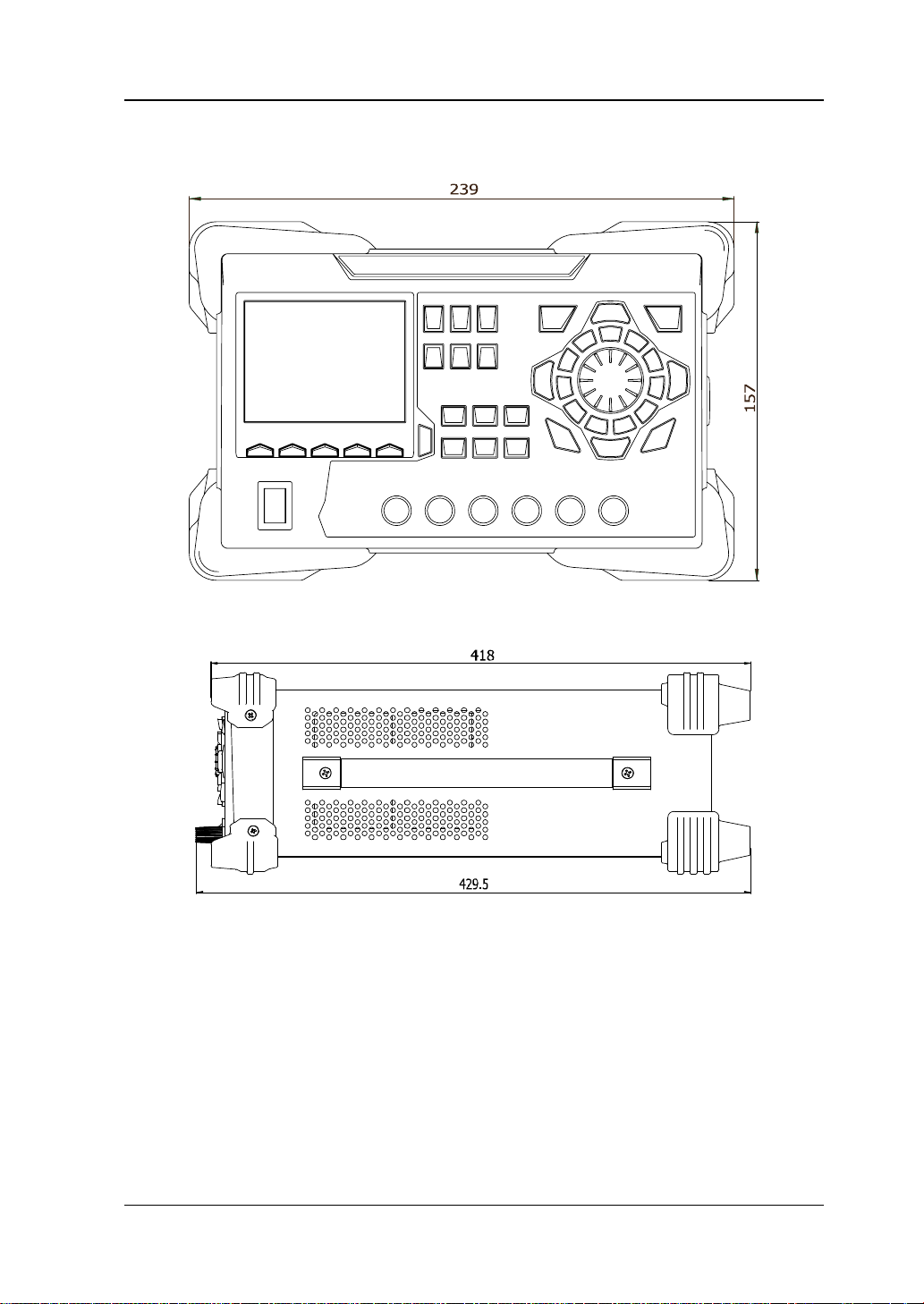
Appearance and Dimensions
Figure 1-1 Front View Unit: mm
Figure 1-2 Side View Unit: mm
DP800A User’s Guide 1-3
Page 18
RIGOL Chapter 1 Quick Start
Front Panel
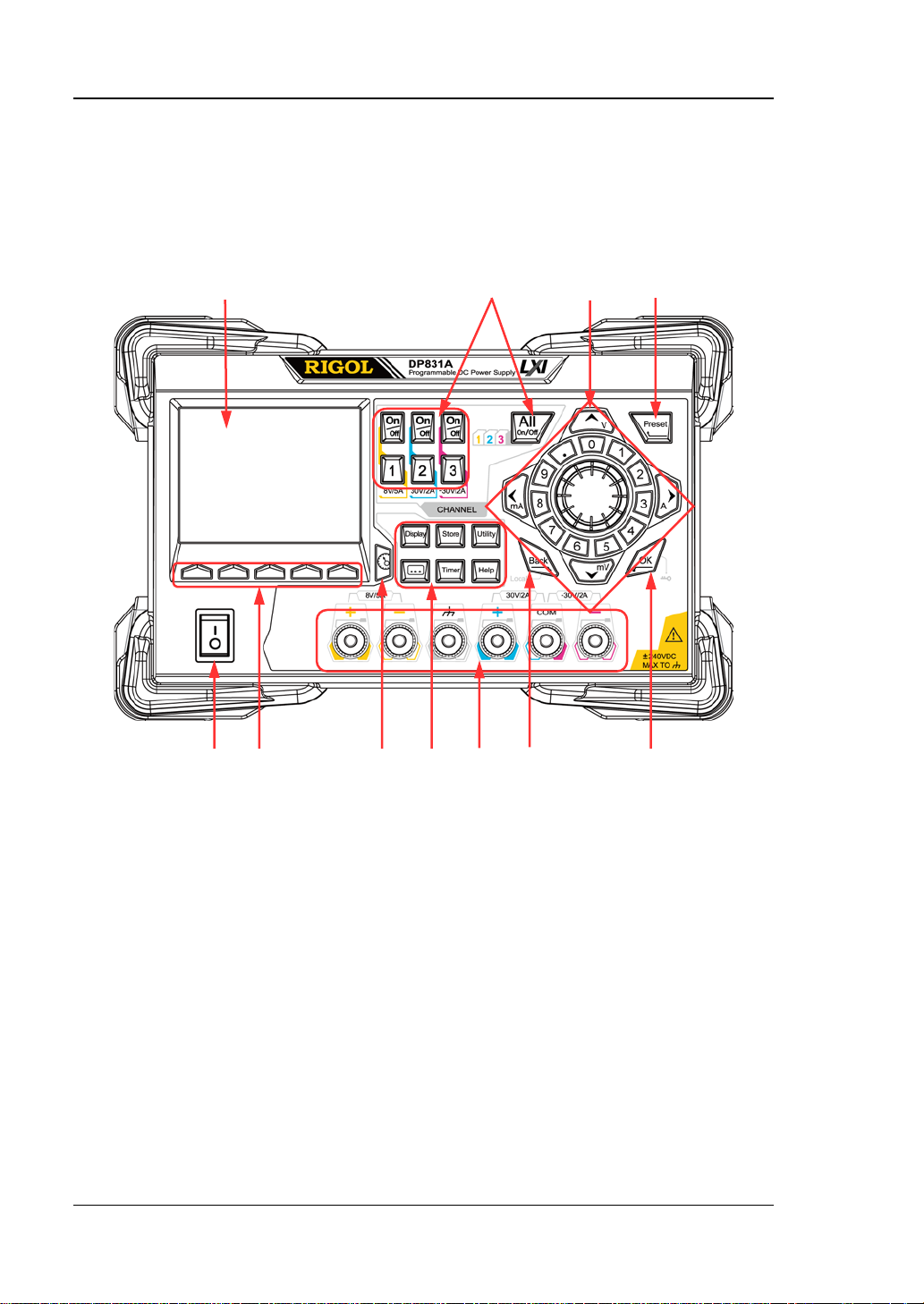
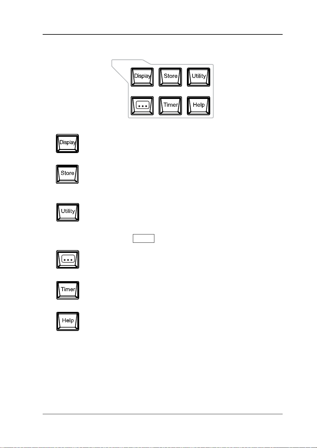
The front panel of DP800A is as shown in Figure 1-3. This section gives a brief
introduction of the function of each part at the front panel.
1 2 3 4
11 10 9 8 7 6 5
Figure 1-3 DP831A Front P anel
1-4 DP800A User’s Guide
Page 19
Chapter 1 Quick Start RIGOL
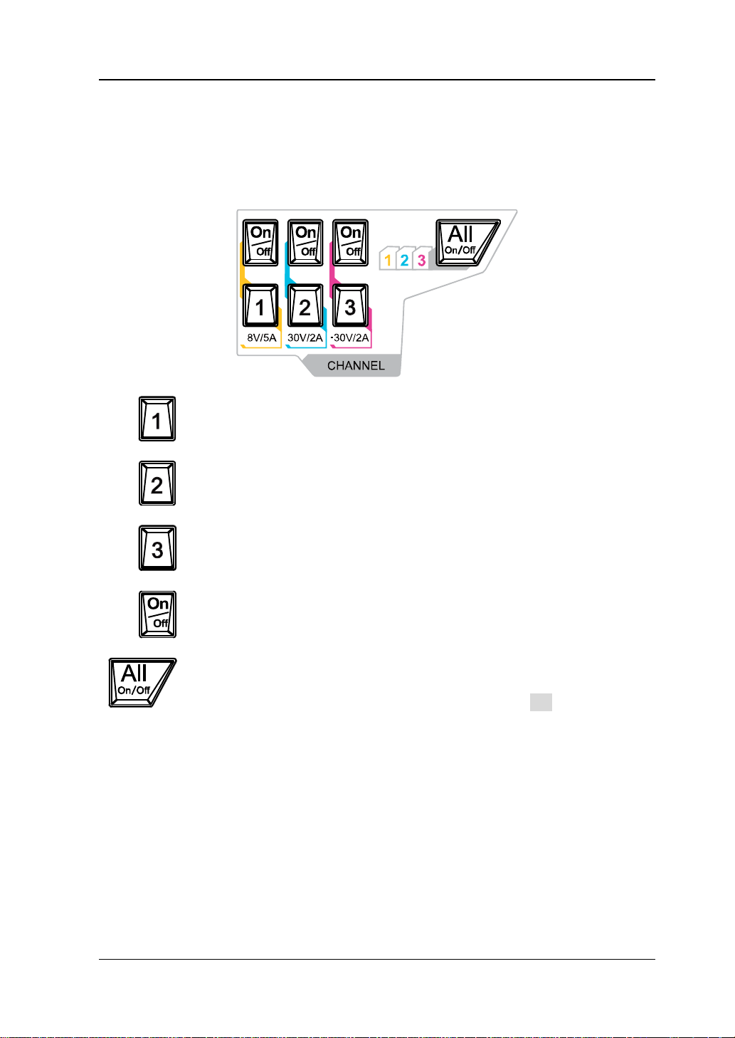
Press this key to select CH1 and set the parameters of this channel,
Press this key to select CH3 and set the parameters of this channel,
1. LCD
3.5 inches TFT display. It is used to display the system parameter setting,
system output state, menu items, prompt messages, etc.
2. Channel Selection and Output Switch
such as voltage, current and overvoltage/overcurrent protection.
Press this key to select CH2 and set the parameters of this channel,
such as voltage, current and overvoltage/overcurrent protection.
such as voltage, current and overvoltage/overcurrent protection.
Press this key to enable or disable the output of the corresponding
channel.
Press this key and the prompt message asking whether to enable the
outputs of all the channels will be displayed. Press OK to enable the
outputs of all the channels. Press this key again, disa ble the outputs of
all the channels.
DP800A User’s Guide 1-5
Page 20

RIGOL Chapter 1 Quick Start
3. Parameter In p ut Area
The parameter input area is as shown in the figure below. This area includes the
direction keys (unit selection keys), numeric keyboard and knob.
(1) Direction keys and unit selection keys
Direction keys: move the cursor. When setting parameters, use the
up/down direction keys to increase or reduce the value at the cursor.
Unit selection keys: whe n usi ng the numeric keyboard to input parameters,
the keys are use d to ente r the voltage units V and mV and the cu rrent units
A and mA.
(2) Numeric Keyboard
Ring-type numeric keyboard: include numbers 0-9 and the decimal point.
Press the corresponding key to input the number.
(3) Knob
When setting parameters, rotate the knob to inc rease or decrease the valu e
of the digit at the cursor.
When browsing the settin g o bje cts (timer parameters, delayer parameters,
filename input, etc), rotate the knob to quickly move the cursor.
1-6 DP800A User’s Guide
Page 21
Chapter 1 Quick Start RIGOL
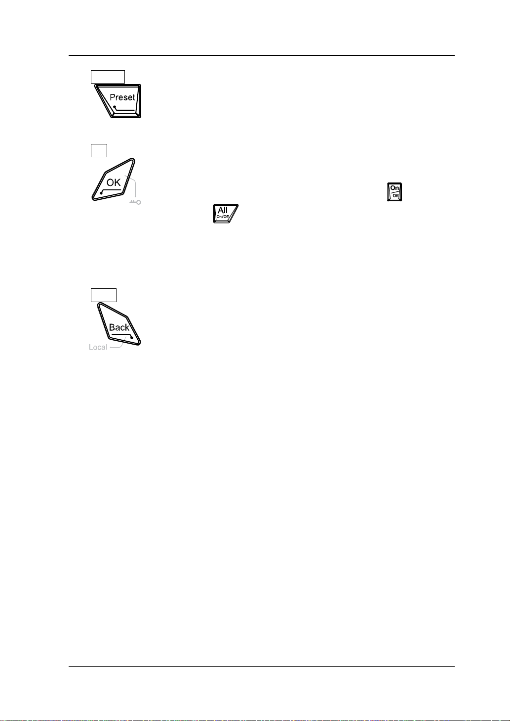
4. Preset
Restore all the settings of the instrument to default values or
recall the user-defined channel voltage/current configurations.
5. OK
Confirm the parameter setting.
Press and hold this key to lock the front panel k eys; at this point,
6. Back
the front panel keys (except the output on/off key
channel and
) are not available. Press and hold this key
of each
again to unlock the front panel keys. When the keyboard lock
password is enabled, you need to input the correct password
(2012) to unlock the front panel keys.
Delete the character currently before the cursor.
When the instrument is in remote mode, p ress this ke y to return
to local mode.
DP800A User’s Guide 1-7
Page 22
RIGOL Chapter 1 Quick Start
B
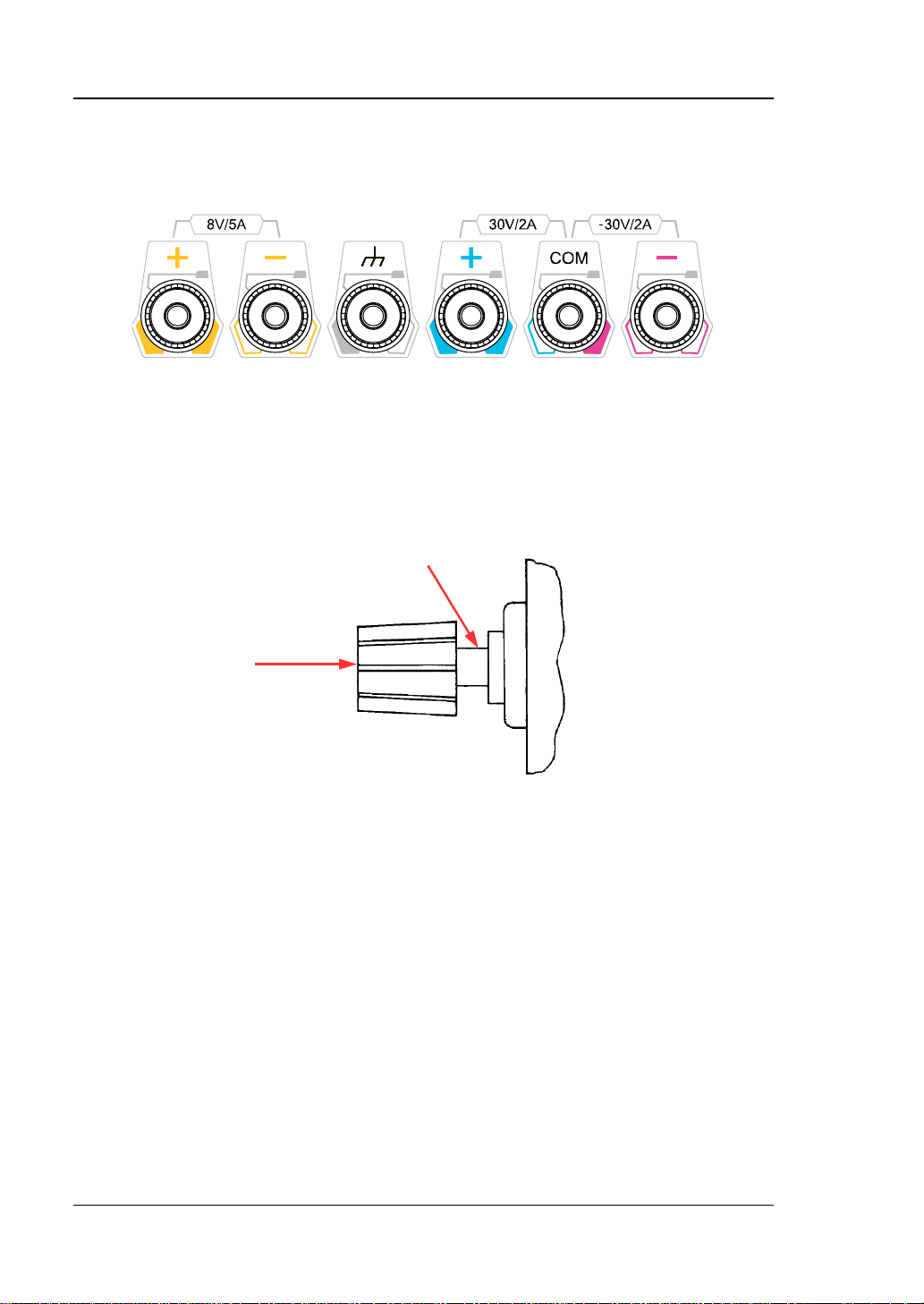
7. Output Terminals
(1) (2) (3) (4)
(1) Output the voltage and current of CH1.
(2) This terminal is connected to the instrument chassis and ground wire
(power cord ground termina l ) and is in grounded state.
(3) Output the voltage and current of CH2.
(4) Output the voltage and current of CH3.
Connection methods of the output terminal:
A
Method 1:
Connect the test lead to A of the output terminal.
Method 2:
Rotate the outer nut of the output terminal counterclockwise and connect
the test lead to B of the output terminal; then, rotate the outer nut of the
output terminal clockwise. This connection method can eliminate the error
caused by the resistance of the output terminal.
Note: Connect the positive terminal of the test lead with the (+) terminal
of the channel output and connect the negative terminal of the test lead
with the (-) terminal of the channel output.
1-8 DP800A User’s Guide
Page 23
Chapter 1 Quick Start RIGOL
Press this key to enter the display parameter setting interface.
Press this key to enter the file store and recall interface. You can
Press this key to enter the advanced function setting interface.
8. Function Menu Area
Users can set the luminance, contrast, RGB luminance and display
mode. Besides, you can also define the start-up interface.
save, read, delete, copy and paste files. The file types available for
storage include state file, record file, timer file and delay file. The
instrument supports internal and external storage and recall.
Press this key to enter the system auxiliary function setting menu.
Users can set the remote interface parameters, system parameters
and print parameters. Besides, users can also calibrate the
instrument, view system information, define the recall
configuration of Preset and install options.
Users can set the recorder, analyzer, monitor and trigger
parameters.
Press this key to enter the timer setting interf ace. Users can set the
timer and delayer p arameters.
Press this key to open the built-in help system and press the
desired k ey t o ge t t he co rr es pon din g h el p i nf o rmation. F or detailed
introductions, refer to “To Use the Built-in Help System”.
DP800A User’s Guide 1-9
Page 24
RIGOL Chapter 1 Quick Start
9. Display Mode Switch/Return to the Main Interface
Switch between the current display mode and dial display mode.
Besides, when the instrument is in a function interface (any
interface under Timer, , Display, Store and Utility),
press this key to exit the f unction interf ace and return to the main
interface.
10. Menu Keys
The menu keys c o rrespond to t he menus above them . P ress any
menu key to selec t the corresponding menu.
11. Power Switch Key
Turn on or off the instrument.
1-10 DP800A User’s Guide
Page 25
Chapter 1 Quick Start RIGOL
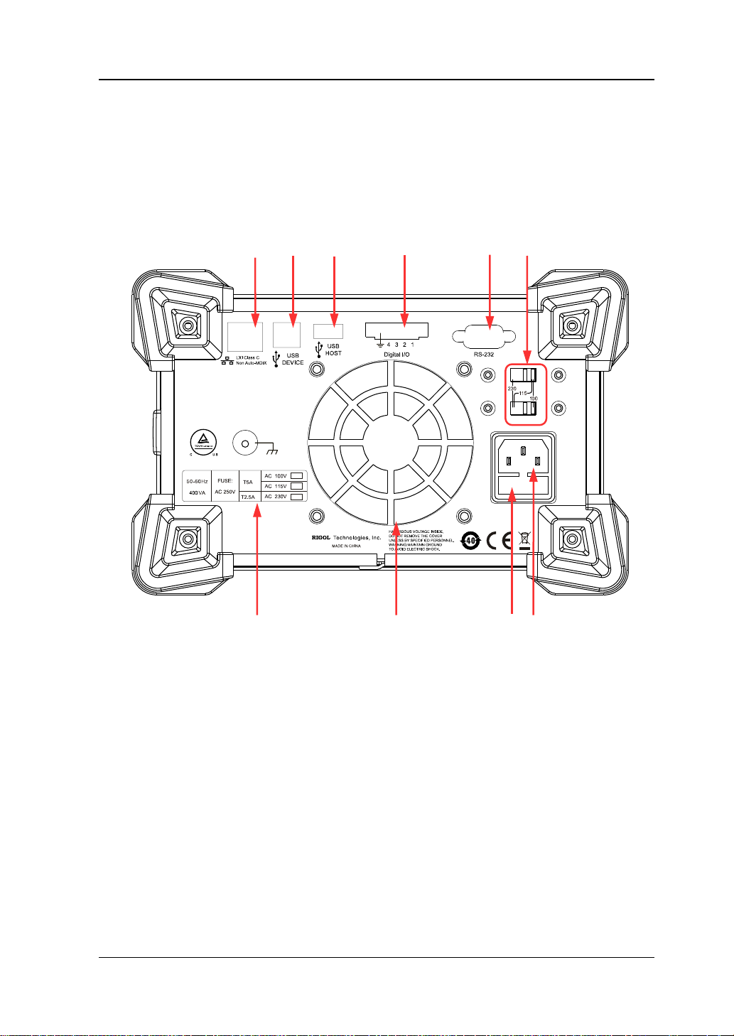
10 9 8 7
1 2 3 4 5 6
Rear Panel
The rear panel of DP800A is as shown in Figure 1-4 and the introduction of each part
is as shown in Table 1-1.
Figure 1-4 DP831A Rear Panel
DP800A User’s Guide 1-11
Page 26
RIGOL Chapter 1 Quick Start
Connect the instrument (as “slave” device) to external
For different models of instrument or when different
Table 1-1 DP831A Rear Panel Explanation
No. Name Explanation
1 LAN Interf ace
The instrument is connected to the local network to
realize remote control.
2 USB DEVICE
USB device (such as: PC) via this interface to realize
remote contr ol .
Connect the instrument (as “host” device) to external
3 USB HOST
USB device (such as: USB storage device) via this
interface.
4 Digital I/O
Digital I/O interface, used to realize the trigger input
and trigger output function.
Serial communication interface. The instrument is
5 RS232 Interface
connected to the PC via this int erface to realize remo te
control.
Select the specification of the input voltage.
DP800A supports three kinds of input voltages;
When the AC line is 100Vac+
6 Voltage Selector
selector to 100;
When the AC line is 115Vac+
selector to 115;
When the AC line is 230Vac+
set the voltage selector to 230.
7 Power Socket AC power input interface.
8 Fuse
input voltages are selected, the specifications of the
fuses are different.
9 Fan
10
Input Power
Requirement
Corresponding relations of the input AC power
frequency, voltage and the specification of the fuse.
10%, set the voltage
10%, set the voltage
10% (maximum 250VAC),
1-12 DP800A User’s Guide
Page 27
Chapter 1 Quick Start RIGOL
Tip
To Connect to Power
1. Input power requirement
DP800A series power supply can accept three kinds of AC power supplies:
50Hz–60Hz frequency; 100V, 115V and 230V voltages.
2. Check the voltage selector at the rear panel
Before connecting to power, make sure that the setting voltage of the voltage
selector at the rear panel matches the input voltage.
3. Check the fuse
When the instrument leaves factory, proper fuse is installed. Please check
whether the fuse matches the input voltage according to the “Input Power
Requirement” at the rear panel.
4. Connect the instrument power cord
Connect the instrument to AC power supply using the power cord provided in
the accessories.
WARNING
To avoid electric shock, make sure that the instrument is correctly
grounded.
Power-on Inspection
Press the power switch at the front panel, the instrument starts and executes
self-test. If the instrument passes the self-test, the welcome interface will be
displayed; otherwise, the corresponding self-test failure information (including the
top board, bottom board, fan and temperature) will be displayed.
When powering on the ins trument after powering off it, make sure that the time
interval between the two operations is greater than 5s.
DP800A User’s Guide 1-13
Page 28
RIGOL Chapter 1 Quick Start
WARNING
To Replace the Fuse
To replace the fuse, follow the steps below.
1. Turn off the instrument and remove the power cord.
2. Insert a small straight screwdrive r into th e slot at the pow er socke t and pri ze out
the fuse seat gently.
Fuse Seat
Fuse
3. Adjust the power voltage selector manually to select the correct voltage scale.
4. Take out the fuse and replace it with a specified fuse (for the corresponding
relations between the input voltage and fuse specification, refer to the “Input
Power R e quirement” at the rear panel).
1-14 DP800A User’s Guide
To avoid personal injuries, cut off the power supply before replacing the
fuse; to avoid electric shock or fire, select the proper power supply
specification and replace a fuse corresponding to this specification before
connecting to pow er.
Page 29
Chapter 1 Quick Start RIGOL
Tip
8 9 10 11
User Interface
DP800A series power supply provides three kinds of display modes (normal,
waveform and dial). The default is normal and press Display Di sp Mode to s et
the display mode to “Waveform” or “Dial”. This section introduces the interface
layout under the normal display mode (as shown in
1
2
3
4
5
6
7
Figure 1-5 DP831A User Interface
Figure 1-8 and Table 1-2).
When the current display mode is “Normal” or “Waveform”, press at the
front panel to switch between the current display mode and dial display mode.
DP800A User’s Guide 1-15
Page 30
RIGOL Chapter 1 Quick Start
1
Voltage and current setting values
2
Overvoltage and overcurrent protection setting values
3
Actual output voltage
10
Channel currently selected
11
Status bar. Display the system status labels.
Table 1-2 DP831A User Interface Explanation
4 Actual output current
5 Actual output power
6 Channel output mode
7 Menu bar
8 Channel number
9 Channel output status
: over-temperature protection is enabled
: the front panel is locked.
: the network is connected.
: USB device is recognized.
: the beeper is enabled.
: the beeper is disabled.
: the instrument is in remote mode.
1-16 DP800A User’s Guide
Page 31

Chapter 1 Quick Start RIGOL
To Use the Built-in Help System
The built-in help s ystem provides help inf ormation f or any f ront panel k ey (except the
parameter input area) and menu keys for users to quickly obtain the function
prompts of the function keys or menus.
Obtain the help information of any key
Press Help to illuminate it and press the desired key to get the corresponding help
information; at the same time, the backlight of Help goes off . Press to
exit the help system.
Built-in help interface
Press Help to illuminate it and press Help again to open the built -in help interface.
Press the up/down direction keys to select the desired help topic and press View to
view the corresponding help information.
The help topics include:
1. View the last displayed message.
2. View error queue of the remote commands.
3. Get the help information of a key.
4. Storage m anagement.
5. Abbreviations list.
6. Get technical support from RIGOL.
DP800A User’s Guide 1-17
Page 32

Page 33

Chapter 2 Front Panel Operations RIGOL
Chapter 2 Front Panel Operations
The contents of this chapter are as follows:
Constant Voltage Output
Constant Current Output
Track Function
Timer and Delayer
Advanced Functions
Display Setting
Store and Recall
Utility
DP800A User’s Guide 2-1
Page 34

RIGOL Chapter 2 Front Panel Operations
Constant Voltage Output
DP800A series power supply provides three output modes: constant voltage output
(CV), constant current output (CC) and critical mode (UR). In CV mode, the output
voltage equals the volta ge set ting v alue a nd the output current is determine d by th e
load; in CC mode, the output current equals the current s etting v alue a nd the outpu t
voltage is determined by the load; UR is the critical mode between CV and CC. This
section introduces the operation method in constant v olt age outp u t m ode.
Operation Method:
1. Turn on the power switch to start the instrument.
2. Select the channel
Select the proper output channel according to the desired output voltage. Pre ss
the corresponding channel selection key; at this point, this channel, its channel
number and output state are high-lighted on the screen.
3. Set the voltage
Method 1
Press Voltage and use the left/right direction keys to move the cursor; then,
rotate the knob to set the voltage and the default unit is V.
Method 2
Press Voltage, use the numeric keyboard to input the desired voltage and press
V or mV or press the unit selection key or to select the desired
unit. Besides, you can also press OK to select the default unit V. During the
input, press Back to delete the character currently before the cursor and press
Cancel to cancel t he input.
4. Set the current
Method 1
Press Current and use the left/right direction keys to move the cursor; then,
rotate the knob to set the current and the default unit is A.
Method 2
Press Current, use the numeric k eyboard to i nput the desire d current and press
A or mA or press the unit selection key or to select the desired unit.
Besides, you can also press OK to select the default unit A. During the input,
press Back to delete the character currently before the cursor and press
Cancel to cancel t he input.
5. Set the overcurrent protection
Press OCP to set the proper overcurrent protection value. For the setting
2-2 DP800A User’s Guide
Page 35

Chapter 2 Front Panel Operations RIGOL
CAUTION
Tip
value, the power supply will swit ch to CC output mode aut omatically. At this point,
method, refer to “Set the current”. Press OCP again to enable the ove rcurrent
protection function and the output will be turned off automatically when the
actual output current is greater than the overcurrent protection value.
6. Connect the output terminals
As shown in the figure below, connect the load to the output terminals of the
corresponding channel.
CAUTION
To avoid damaging the instrument or the device connected to it, pay
attention to the polarity when connecting.
7. Turn on the output
Turn on the output of the corresponding channel and the actual output voltage,
output current, output power as well as the output mode (CV) are high-lighted
in the user interface.
Warning
To avoid electric shock, please turn on the output switch after the
output terminals are correctly connected.
When the fan stops, the channel switch can not be turned on;
otherwise, “The fan stops, stop the output!” will be displayed.
8. Check the output mode
In constant voltage output mode, the output mode displayed should be “CV”; if
“CC” is displayed, you can increase the current setting value properly and the
power supply will switch to CV mode automatically.
In CV output mode, when the load current is greater than the current setting
the output current equals the current set ting value a nd the output v oltage redu ces
proportionally.
DP800A User’s Guide 2-3
Page 36

RIGOL Chapter 2 Front Panel Operations
CAUTION
Constant Current Output
In constant current output mode, the output current equals t he cur rent setting v alue
and the output voltage is determined by the load. This section introduces the
operation method in constant current output mo de.
Operation Method:
1. Turn on the power switch to start the instrument.
2. Select the channel
Select the proper output channel accordi ng t o the desired output current. Press
the corresponding channel selection key; at this point, this channel, its channel
number and output state are high-lighted in the center of the screen.
3. Set the voltage
Press Voltage to set proper voltage according to “S et the voltage” in
“Constant Voltage Out put”.
4. Set the current
Press Current to set proper c u rrent according to “Set the current” in
“Constant Voltage Output”.
5. Set the overvoltage protection
Press OVP to set the proper over voltage protection value. For the setting
method, refer to “Set the voltage” in “Constant Voltage Output”. Press OVP
again to enable the overvoltage protection function and the output will be
turned off automatically when the actual output voltage is greater than the
overvoltage protection value.
6. Connect the output terminals
As shown in the figure below, connect the load to the output terminals of the
corresponding channel.
7. Turn on the output
2-4 DP800A User’s Guide
To avoid damaging the instrument or the device connected to it, pay
attention to the polarity when connecting.
Page 37

Chapter 2 Front Panel Operations RIGOL
Warning
CAUTION
Tip
value, the power supply will swit ch to CV output mode automati cally. At this point,
Turn on the output of the corresponding channel and the actual output voltage,
output current, output power as well as the output mode (CC) are high-lighted
in the user interface.
To avoid electric shock, please turn on the output switch after the
output terminals are correctly connected.
When the fan stops, the channel switch can not be turned on;
otherwise, “The fan stops, stop the output!” will be displayed.
8. Check the output mode
In constant current output mode, the output mode displayed should be “CC”; if
“CV” is displayed, you can increase the voltage setting value properly and the
power supply will switch to CC mode automatically.
In CC output mode, when the load voltage is greater than the voltage setting
the output voltage equals the volta ge setting v alue a nd the output current reduces
proportionally.
DP800A User’s Guide 2-5
Page 38

RIGOL Chapter 2 Front Panel Operations
Model
CH1
CH2
CH3
DP832A
Support
Support
Not support
When the track f unction is enabled, the volta ge of the t racking channe l cannot
Track Function
Some of the DP800A channels support the output track function (as shown in the
table below).
DP831A Not support Support Support
For two channels supporting the track function, when the track function of one
channel (the tracked channel) is enabled, the voltage setting value of the other
channel (the tracking channel) will change accordingly when the voltage setting
value of this channel is changed. By default, the track function is disabled and it is
usually used to provide symmetric voltage for the calculation amplifier or other
circuits.
Operation Method (Take DP831A for example):
1. Turn on the power switch to start the instrument.
2. Enable the track function
Select CH3 and press Track to enable the track fun ction. At t his point, the t rac k
status label
3. Set the voltage
Press Voltage to set proper voltage. At this point, the voltage of CH2 changes
accordingly. For example, set the voltage of CH3 to -5V and the voltage of CH2
will change to +5V automatically.
4. Disable the track function
Select CH3 and press Track to disable the track function.
is displayed in the CH2 area in the user interface.
Tip
The track function onl y tracks the voltage setting value and the actual output
voltage will not be affected.
be set.
2-6 DP800A User’s Guide
Page 39

Chapter 2 Front Panel Operations RIGOL
Tip
The timer function and delayer function are mutually exclusive. When the timer is
Timer and Delayer
DP800A provide s the timer and delayer functions.
When the timer is enabled, the instrument outputs the preset voltage and current
values (at most 2048 groups). Users can set the number of output groups of the
timer as well as the voltage, current and timing time of each group. Besides, the
instrument provides various built-in output templets and users can sel e ct and edit
the templet as well as create timer parameters based on the templet. The instrument
will output according to the parameters currently created.
When the delayer is enabled, the instrument enables or disables the output
according to the preset state and delay time (at most 2048 groups). Users can set
the number of output groups of the delayer as well as the state and delay time of
each group.
Users can store the edited timer parameters (timer file, with the suffix “*.RTF”) and
delayer parameters (delay file, with the suffix “*.RDF”) in internal or external
memory and recall them when required.
Press Timer to illuminate it. The timer and delayer setting interface is displ ayed.
1. Timer Set: To Set the Timer Parameters
2. Timer: To En able the Timer
3. Delay Set: To Set the Delayer Parameters
4. Delayer: To Enable the Delayer
enabled, Delayer is gra yed out and disabled; when the delayer is en abled, Timer
is grayed out and disabled.
DP800A User’s Guide 2-7
Page 40

RIGOL Chapter 2 Front Panel Operations
To Set the Timer Parameters
Press Timer Timer Set to enter the timer parameter setting interface as shown
in the figure below. The channel currently selected is displayed in the status bar.
Press the channel selection keys at the front panel to switch channel. This interface
provide s timer parameter preview; the horizontal axis represents time and the
vertical axis represents v oltage a nd current; users ca n view the values on t he current
page of the parameter list.
Timer Parameter Preview Channel Currently Selected Timer Parameter List
Figure 2-1 Timer Parameter Setting Interface
Number of Groups
The number of groups is defined as the number of groups of preset voltage and
current values that the power supply outputs in each cycle. Press Groups and use
the knob or numeric keyboard to input the value. The range is from 1 to 2048.
2-8 DP800A User’s Guide
Page 41

Tip
Chapter 2 Front Panel Operations RIGOL
Number of Cycles
The number of cycles is defined as the number of times that the i nstrument performs
timing output according to the preset voltage and current. Press Cycles to set the
number of cycles to “Infinite” or use the knob or numeri c keyboard to input t he value .
The range is from 1 to 99999.
The total number of groups in each timing output = the number of groups ×
the number of cycles
The power supply wil l terminate the timer function when the total number of
groups of output s is finished. At this point, the state of the power supply
depends on the setting of End State.
End State
The end state refers to the state of the instrument after it finishes outputting the
total number of gr oups of voltage an d cur rent v alues when t he num be r of cy cles is a
specif ied value. Press End State to select “Outp Off” or “Last”.
Outp Off: the instrument turns off the output automatically after finishing the
output.
Last: the instrument stops at the output state of the last group after finishing
the output.
Note: When the number of cycles is set to “Infinite”, the end state is invalid.
To Manually Edit the Timer Parameters
You can e dit the timer parameters manually . Press Parameter and use the left/right
direction keys to select the number (No.) in the timer parameter list, use the
up/down direction keys to select the voltage (Volt), current (Curr) and time ( Set) of
the current group respectively and use the numeric keyboard or direction keys and
knob to input the desired value. Use the same method to set the parameters of the
other groups.
You need to set the parameters of number 0 to number (P-1); wherein, P is the
number of output groups currently set. Only 6 groups of parameters can be
displaye d on each page of the timer parameter list an d you can press
view and set the parameters of the other groups. This interface provides timer
parameter preview; the horizontal axis represents time and the vertical axis
represents voltage and current; users can view the v alues on the current page of the
parameter list.
or to
DP800A User’s Guide 2-9
Page 42

RIGOL Chapter 2 Front Panel Operations
To Edit the Timer Parameters using Templet
The instrument provides various built-in output templets and users can select and
edit the templet as well as create timer parameters based on the templet. The
instrument will output according to the parameters currently created.
Press Timer Timer Set and press Templet to open t h e templet edit menu.
1. Select the editing object
Press Edit Obj to select “Voltage” or “current”.
Voltage: when it is selected, press Current and use the numeric keyboard
or direction keys and kn ob to set the current value. Then, sele ct the templet
and edit the templet parameters. The interface displays the voltage
preview.
Current: when it is selected, press Voltage and use the numeric keyboard
or direction keys an d knob to set the voltage v alue. Then, s elect the templet
and edit the templet parameters. The interface displays the current
preview.
2. Select the templet
Press Type to select the desired templet, including Sine, Pulse, Ramp, Stair Up,
Stair Dn, StairUpDn, Exp Rise and Exp Fall.
Sine
The Sine waveform is as shown in the figure below. The instrument
determines the Sine amplitude according to the maximum and minimum
currently set and determines the Sine pe ri od according t o the total number
of points (denoted by P) and the time interval currently set, thus
determining the Sine w av eform. When creating par ameters, the instrument
draws P values from the preset Sine waveform according to the current
time interval.
T
Pulse
The Pulse waveform is as shown in the figure below. The timer parameters
created from Pulse wavef orm only contain two points.
The first point: the amplitude (voltage or cu rrent) is determined by the high
level set; the time equals the pulse width currently set.
The second point: the amplitude (voltage or current) is determined by the
low level set; the t ime equals the period currently s et minus the pulse wi dth
currently set.
2-10 DP800A User’s Guide
Page 43

Chapter 2 Front Panel Operations RIGOL
T
t
Tip
T
t
Symmetry=t/T*100%
When Pulse is selected, if you want t o output more than 2 groups of timer
parameters, you can output the timer parameters created from the Pulse
templet repeatedly by increasing the number of cycles.
Ramp
The Ramp waveform is as shown in the figure below. The instrument
determines the amplitude of the Ramp according to the maximum and
minimum currently set, determines the period according to the total
number of points (deno t ed by P) and the time interval currently set and
determines the Ramp waveform according to the symmetry (denoted by
Sym) currently set. When creating parameters, the instrument draws
[1]
int(P*Sym)
values from the rising edge of the preset Ramp waveform at
the same time interval and draws P- int(P*Sym) values from the fa lling
edge of the preset Ramp waveform at the same time interval. The timing
time is determined by the time interval currently set.
[1]
Note
: int(P*Sym) refers to rounding P*Sym (discard the decimal part).
Stair Up
The Stair Up waveform is as shown in the figure below. The instrument
determines the Stair Up waveform accor ding to the maximum (denoted by
MAX), minimum (denoted by MIN), total number of p oints (den ote d by P,
P≥10) and time interval currently set and creates P parameters from MIN
to MAX at the step of (MAX-MIN)/(P-1). The timing time is determined
by the time interval currently set.
Stair Up
DP800A User’s Guide 2-11
Page 44

RIGOL Chapter 2 Front Panel Operations
Stair Dn
The Stair Dn waveform is as shown in the figure below. The instrument
determines the Stair Dn waveform according to the maximum (denoted by
MAX), minimum (denoted by MIN), total number of points (denoted by P)
and time interval currently set and creates P parameters from MIN to MAX
at the step of (MAX-MIN)/(P-1). The timing time is determined by the
time interval currently set.
Stair Dn
StairUpDn
The StairUpDn waveform is as shown in the figure below. The instrument
determines the StairUpDn waveform according to the maximum (denoted
by MAX), minimum (denoted by MIN), total number of points (denoted by
P) and time interval currently set and creates P parameters. When P is an
odd number, the value increase from MIN to MAX at the step of
(MAX-MIN)/int(P/2)
[1]
and then reduces to MIN at the same step.
When P is an even number, the value increases from MIN to MAX at the
step of (MAX-MIN)/int(P/2-1) and then reduces to MIN at the step of
(MAX-MIN)/int(P/2). The timing ti me is deter mined by the time inter v al
currently set.
StairUpDn
[1]
Note
: int(P/2) indicates rounding P/2.
Exp Rise
The Exp Rise waveform is as shown in the figure below. The instrument
determines the Exp Rise waveform according to the maximum (denoted by
MAX), minimum (denoted by MIN), total number of points (denoted by P)
and rise index (denoted by RiseIndex) currently set. The wavefo r m
function is (MAX-MIN)*[1-e
-i*RiseIndex/P
]; wherein, i is independent
variable and creates P groups of parameters from 0 to (P-1). The timing
time is determined by the time interval currently set.
2-12 DP800A User’s Guide
Page 45

Chapter 2 Front Panel Operations RIGOL
Note
Exp Rise
Exp Fall
The Exp Fall waveform is as shown in the figure below. The instrument
determines the Exp Fall waveform according to the maximum (denoted by
MAX), minimum (denoted by MIN), total number of points (denoted by P)
and fall index (denoted by FallIndex) currently set. The waveform function
is (MAX-MIN)*e
-i*FallIndex/P
; wherein, i is independent variable and
creates P groups of parameters from 0 to (P-1). The timing time is
determined by the time interval currently set.
Exp Fall
When the templet c urrently sele cted is Exp Rise or Exp Fall, the timer parameters
created cannot reach the maximum or minimum due to the characteristic of the
exponential function. The ran ge of the timer parameters created is related to the
rise index or fall index currently set. The larger the rise index or fall index is, the
larger the range of the tim er parameters will be, as shown in the figures below
(maximum=8, minimum=0, total number of points=100, rise index/fall index are
1, 4, 7 and 10 respectively).
DP800A User’s Guide 2-13
Page 46

RIGOL Chapter 2 Front Panel Operations
Templet
Parameter
Sine
Max Value, Min Value, Points, Interv a l, Inverted
StairUpDn
Max Value, Min Value, Points, Interval
Exp Rise
Max Value, Min Value, Points, Interval, Rise Index
3. Edit the templet parameters
After selecting the desired templet, set the templet parameters. Fo r different
templets, the parameters to be set are different as shown in Table 2-1.
Table 2-1 Templet Parameters
Pulse Hi Level, Lo Level, Width, Period, Inverted
Ramp Max Value, Min Value, Points, Interval, Symmetry, Inverted
Stair Up Max Value, Min Value, Points, Interval
Stair Dn Max Value, Min Value, Points, Interval
Exp Fall Max Value, Min Value, Points, Interval, Fall Index
Max Value
Set the maximum voltage or current of the templet currently selected. The
range is related to the channel currently selected.
Min Value
Set the minimum voltage or current of the templet currently selected. The
range is related to the channel currently selected. The minimum cannot be
greater than the maximum currently set.
Points
The total number of points refers to the number of groups of timer
parameters created using the templet currently selected. The range is from
10 to 1048.
When the total number of points ( denote d by P) and the current number of
output groups (denoted by G) are different, P groups of parameters will be
created using the templet and then, the number of output groups will
change to P automatically.
Interval
The interval refers to the time required for the instrument to output each
group of ti mer parameters created using the templet currently selected and
the range is from 1s to 99999s.
Inverted
When the templet currently selected is Sine, Pulse or Ramp, if Inverted is
enabled, the instrument will first turn the preset waveform upside do wn
and then create timer parameters.
2-14 DP800A User’s Guide
Page 47

Chapter 2 Front Panel Operations RIGOL
Hi Level
When the templet currently selected is Pulse, set the high level of the Pulse
and the range is related to the channel currently selected.
Lo Level
When the templet currently selected is Pulse, set the low level of the Pulse
and the range is related to the channel currently selected. The low level
should not be greater than the high level currently set.
Width
When the templet currently selected is Pulse, set the pulse width of the
Pulse (namely the du ratio n of high level withi n a period). The range is from
1 to (Period-1) and the unit is s econd.
Period
When the templet currently selected is Pulse, set the period of the Pulse
and the range is from 2s to 99999s.
Symmetry
When the templet currently selected is Ramp, set the symmetry of the
Ramp (namely the ratio of the dura tion of the rising edge within a period to
the whole period) and the range is from 0% to 100%.
Rise Index
When the templet currently selected is ExpRise, set the r ise index of the
ExpRise and the range is from 0 to 10.
Fall Index
When the templet currently selected is ExpFall, set the fall index of the
ExpFall and the range is from 0 to 10.
4. Create the timer parameters
After setting all the parameters, press Construct to construct th e timer
parameters. The timer parameters constructed are displayed in the timer
parameter list as shown in
Figure 2-2.
Save and Read
You can store the timer parameters edited manually or created using the templet in
internal or external memory and recall them when required.
1. Save
After editing the timer parameters, press Save to enter the store and recal l
interface, the file type is fixed at “*.rtf” and please save the file according to the
introduction in “
Store and Recall”.
DP800A User’s Guide 2-15
Page 48

RIGOL Chapter 2 Front Panel Operations
Tip
2. Read
Press Read to enter the st ore and recall int erface , the file type is fixed at “*.rtf”
and please read the desired file according to the introduction in “
Recall”. Users can edit the timer file read.
Store and
To Enable the Timer
After setting the timer parameters, pr es s Timer Timer to enable the timing
output. The timing output interface is as shown in the figure below.
Figure 2-2 Timing Output Interface
Enabling the timer will change the output value of the channel; make sur e
that the change in the output value will not affect the device connected to
the power supply be fore enabling the timer.
The timing output is valid only when both the timer and the channel output
are turned on.
When the timer is enabled, the timer parameters cannot be modified and
Delayer is grayed out and disabled.
2-16 DP800A User’s Guide
Page 49

Chapter 2 Front Panel Operations RIGOL
To Set the Delayer Parameters
Press Timer Delay Set to enter the delayer para meter setting interface as shown
in the figure below. The channel currently selected is displayed in the status bar.
Press the channel selection keys to switch channel. This interface provides delayer
parameter preview. Users can view the values on the current page of the delayer
parameter list. High level indicates turning on the output and low level indicates
turning off the output.
Delayer Parameter Preview Channel Currently Selected Delayer Parameter List
Figure 2-3 Delayer Parameter Setting Interface
Number of Groups
The number of groups ref ers to the nu mber of time s that the instrument tu rns on or
off the output according to the preset state. Press Groups and u s e th e kn ob or
direction keyboard to input the value. The range is from 1 to 2048.
Number of Cycles
The number of cycles refers to the number of times that the instrument performs
delay output according to the preset state. Press Cycles to set the number of cycles
to “Infinite” or use the knob or n umeric ke yboa rd t o in put the v alue an d the ra nge is
from 1 to 99999.
DP800A User’s Guide 2-17
Page 50

RIGOL Chapter 2 Front Panel Operations
Tip
The total number of groups in each delay output = the number of groups ×
the number of cycles
The power supply will terminate the delayer function when the total number
of groups of delays is finished. At this point, the state of the power supply
depends on the setting of End State.
End State
The end state refers to the state of the instrument when the delayer stops. Press
End State to select “Outp On”, “Outp Off” or “Last”.
Outp On: the instrument turns on the output automatically.
Outp Off: the instrument turns off the output automatically.
Last: the instrument stops at the output state of the last group.
To Edit the Delayer Parameters Manually
You can edit the dela yer parameters manually. Press Parameter and use the
left/right direction keys to s elect t he number (No.) in the delayer par ameter list, use
the up/down direction keys to select the state (State) and time (Delay) of the current
group respectively. After selecting the state (State), press OK to switch to the
desired state and after selecting the time (Delay), use the numeric keyboard or
direction keys and knob to input the desired value. Use the same method to set the
parameters of the other groups.
You need to set the parameters of number 0 to number (P-1); wherein, P is the
number of output groups currently set. Only 6 groups of parameters can be
displaye d o n ea ch page of the dela yer parameter list and you can press
to view and set the parameters of the other groups. This interfac e p rovides d e lay er
parameter preview and users can view the v alues on the cu rrent page of t he d elay er
parameter list. High level indicates turning on the output and low level indicates
turning off the output.
or
To Generate State Automatically
Press Timer Delay Set State Gen to select “0 1 Patt” or “1 0 Patt”.
0 1 Patt: the state is set to “Off” and “On” alternately.
1 0 Patt: the state is set to “On” and “Off” alternately.
2-18 DP800A User’s Guide
Page 51

Chapter 2 Front Panel Operations RIGOL
To Generate Time Auto mat ic ally
1. Select the generation method
Press Timer Delay Set Time Gen Method to select t he desir ed
generati on method.
FixTime
Users can set the durat i on of the “On” or “Off” state.
Increase
The duration is generated in monotonic increase mode.
Decline
The duration is generated in mon otoni c decline mo de.
2. On Delay/Off Delay
When the time generation method is “FixTime”, users can set the duration of the
“On” or “Off” state.
On Delay: set the duration of the “On” state and the range is from 1s to 99999s;
Off Delay: set t he dur ation of the “Off” state and the range is from 1s to 99999s.
3. Base Val and Step
When the time gener at ion method is “Increase” or “Decline”, set the base value
and step of time generation. The two fulfills the relation: time base value +
number of output groups*step ≤99999s.
Stop Condition
The instrument monitors the out put volta ge, current and power d uring dela y output.
You can set a condition and the instrument stops the delay output when state that
fulfills this condition is detected.
Press Timer Delay Set Stop Con to set the stop condition to “None”, “<
Voltage”, “> Voltage”, “< Current”, “> Current”, “< Power” or “> Power”. After
selecting the desired condition, use the numeric ke yboard or dire ction keys and knob
to input the desired value.
DP800A User’s Guide 2-19
Page 52

RIGOL Chapter 2 Front Panel Operations
Tip
Save and Read
You can save the delayer parameters edited manually or generated automatically in
internal or external memory and recall them when required.
1. Save
After finishing editing the delayer parameters, press Save to enter the store and
recall interface, the file type is fixed at “*.rdf” and please save the file according
to the introduction in “
2. Read
Press Read to enter the st ore and re call interface , the file type is fixed at “*.rdf”
and please read the desired file according to the introduction in “
Recall”. Users can edit the delay file read.
Store and Recall”.
Store and
To Enable the Delayer
After setting the delayer parameters, press Timer Delayer to enable the delay
output. The delay output interface is as shown in the figure below.
Figure 2-4 Delay Output Interface
Enabling the delayer will change the output state of the channel. Please
make sure that the change of the output state will not affect the devices
connected to the power supply before enabling the delayer.
When the delayer is enabled, the delayer parameters cannot be modified
and Timer is grayed out and disabled .
2-20 DP800A User’s Guide
Page 53

Chapter 2 Front Panel Operations RIGOL
Advanced Functions
DP800A pro vides various advanced functions, including the recorder, analyzer,
monitor and trigger. Press
1. Recorder: record the output state of each channel and store the record file.
2. Analyzer: analyze the record file saved.
3. Monitor: monitor the output of each channel and turn off the output, display
the corresponding prompt message or sound the beeper when the monitor
condition is met.
4. Trigger: the rear panel provides a digital I/O interface which supports trigger
input and trigger output.
Trigger Input: the data lines of the digital I/O interface receive external
trigger signal. The source under control (namely the output channel) turns
on the output, turns off the output or inverts the output state when the
preset trigger condition is met.
Trigger Output: the data lines of the digital I/O i nterf ace output the level o r
square signal when the output of the control source (namely the output
channel) meets the preset trigger condition.
to open the advanced function setting interface.
DP800A User’s Guide 2-21
Page 54

RIGOL Chapter 2 Front Panel Operations
Recorder
When the recorder is enabled, users can record the current state of the instrument
and if analyzer is installed, users can also analyze the file recorded.
Press Recorder to open the recorder setting interface. You can turn on or
off the recorder function, set the record period and select the store destination.
1. Switch
Press Switch to turn on or off the recorder and the default is “Off”. When the
recorder is turne d o n, the record period and destination cannot be set. The
instrument samples and records the output of each channel accord ing to the
current record period. When the recorder is turned off, the current record is
finished and the instrument prompts you to sav e t he file recorded (press OK to
save the file).
Note: During the record, make s ure that the out put of ea ch channel is enable d;
otherwise, the record data will be 0.
2. Record Period
The record period is the time interval at which the instrument samples and
records the output of each channel when the recorder is turned on. Press
Period and use the numeric keyboard or direction keys and knob to set the
record period of the recorder . The range is from 1s to 99999s and the default is
1s.
3. Destination
Before turning on the recorder, select the store destination. Press Dest to enter
the store and recall interface and the file type is fixed at “*.rof”. You can store
the file recorded in internal or external memory. After selecting the desired
destination, press Save, input the desired filename and press OK (for the
detailed operations, refer to the introduction in “
finishing the record, the instrument stores the record file with the specified
filename to the specified destination.
Store and Recall”). After
2-22 DP800A User’s Guide
Page 55

Chapter 2 Front Panel Operations RIGOL
Analyzer
The analyzer can analyze the file recorded and provides the analysis results,
including the numbe r of groups, median , mode as well as the average, VAR, range,
minimum, maximum a nd mean deviation of the volt age, current or pow er of diff erent
channel.
Press Analyzer to open the analyzer setting interface. You can open the
record file stored, set the analyzer parameters, execute the analysis and view the
analysis results.
1. Open the File
Press Open File to enter the store and recall interface, the file type is fixed at
“*.rof”, select the desired record file and press Read. At this point, the current
time and start time are 1s and the end time is the maximum record time of the
file opened.
The following operations are valid only when valid record file is opened.
2. Set the Parameters
Start Time
Press Start Time and use the knob or numeric keyboard to set the start
time of the current analysis file. The range is from 1 to the end time.
End Time
Press End Time and use the knob or numeric keyboard to set the end time
of the current analysis file. The range is from the start time to the
maximum record time of the file opened.
3. Execute the Analysis
After opening the record f ile and setting the start time and end time, press
Analyze and the instrument will start to analyze according to the current
setting.
4. View the Analysis Results
Analysis object
After executing the analysis operation, press Object to select voltage,
current, power or all and the analysis results of the object currently
selected will be displayed at the bottom of the screen. When “All” is
selected, press
the corresponding analysis results.
Display Type
After opening the record file and setting the start time and end time, the
data between the start time and end time in the record file currently
opened will be displayed in both figure and table forms on the screen. Press
or to switch the current analysis object an d view
DP800A User’s Guide 2-23
Page 56

RIGOL Chapter 2 Front Panel Operations
Disp Type continuously to switch between figure and table forms.
Figure: display the voltage, current and power of the current record file in
figure form (the voltage, current or pow e r corresponding to the current
time is displayed above the figure) and each group of measurement values
of each object are connected in linear interpolation mode, clearly showing
the variation tendency. You can press Object to switch among voltage,
current and power.
Table: display each group of voltage, current and power of the current
record file in table form.
Curr ent Time
Use the knob or numeric keyboard to quickly locate each group of data of
the current record file between the start time and end time. If the current
2-24 DP800A User’s Guide
Page 57

Chapter 2 Front Panel Operations RIGOL
display mode is figure, the interf ace will locate t he current data using cursor
line in the same color of the current analysis channel (the voltage, current
or power corresponding to the current time is displayed above the figure).
The range is from the start time to the end time.
Tip
You can switch the channel to be analyzed according to the channel number.
DP800A User’s Guide 2-25
Page 58

RIGOL Chapter 2 Front Panel Operations
Monitor
The monitor can monitor the current output state of the instrument. When the
user-defined monitor condition is met, the instrument executes the corresponding
operation according to the setting in “Stop Mode”.
Press Monitor to o pen the monitor set ting inter face. T he s tatus b ar sho w s
the channel currently sele cted. Press the channel s election ke ys at the f ront panel to
switch the channel.
Note: The instrument can monitor the output states of multiple channels
simultaneously.
1. Monitor Condition
The monitor condition can be any logic combination of the voltage, current and
power and users can also set the voltage, current and power values.
Press Condition and use the direction keys and OK to set the desired monitor
condition.
2. Voltage
Press Voltage and use the numeric keyboard or direction keys and knob to set
the voltage in the monitor condition.
3. Current
Press Current and use t he numeric key b oard or direc tion keys and knob to set
the current in the monitor condition.
4. Power
Press Power and use the numeric keyboard or direction keys and knob to set
the power in the monitor condition.
5. Stop Mode
Press Stop Mode, use the direction keys a nd OK to set the stop mode (“Output
Off”, “Warning” and “Beeper”) and multiple modes can be selected. When the
channel output state meets the monitor condition set, the instrument will turn
off the output, dis pl ay the corres ponding prompt message or sound the beeper
according to the stop mode selected.
6. Switch
Press Switch to turn on or off the monitor function.
2-26 DP800A User’s Guide
Page 59

Chapter 2 Front Panel Operations RIGOL
Trigger
The rear panel of DP800A provides a digital I/O interface (as shown below) which
supports trigger input and trigger output.
Trigger Input:
The data lines of the digital I/O interface receive external trigger signal. The
source under c ont rol (nam ely the out put channel ) turns on the output, turns off
the output or inverts the output state when the preset trigger condition is met.
Trigger Output:
The data lines of the digital I/O interface out put lev e l or squa re si gnal w hen t he
output of the control source (namely the output channel) meets the preset
trigger condition.
The 4 data lines are mutually independent and can be used as trigger input line or
trigger output line separately.
Press Trigger to open the trigger setting interface as shown in the f igure
below. Press Trig to select “In” or “Out” to switch between the trigger input and
trigger output setting interfaces and the default is trigger input.
Figure 2-5 Trigger Setting Interface
DP800A User’s Guide 2-27
Page 60

RIGOL Chapter 2 Front Panel Operations
Trigger Input
When signal th at meets the current trigger type is input on the specified data line,
the specified source under control will turn on the output, turn off the output or
toggle the output state according to the setting in output response.
Press Trigger Trig to select “In” to enter the interface as shown in
Figure 2-9.
1. Data Line
Press Data Line to select D0, D1, D2 or D3 and the data line cur rently s electe d
will be highlighted in the s creen. Use rs can set the tr igger conditions of the f ou r
data lines respectively.
2. Source under Control
Press Ctrled Src to select one or more channels as the source under control.
3. Trigger Type
Press Trig Type to select to t rigger on the risin g edge, falling e dge, high level or
low level of the input signal.
4. Output Response
Press Outp Resp to set the output response type.
Output On: when the trigger condition is met, turn on the output of the
channel currently selected as the source under control.
Output Off: when the trigger condition is met, turn off the output of the
channel currently selected as the source under control.
Output Toggle: when the trigger condition is met, toggle the output state of
the channel currently selected as the source under control.
5. Sensitivity
Press Sensitivity to set the sensitivity to high, middle or low . Selectin g
relatively lower trigger sensitivity can avoid mis-trigger at the noise.
6. Enable
Press Enable to enable or disable the trigger input. When it is enabled, the
instrument triggers when the input signal meets the trigger condition set.
2-28 DP800A User’s Guide
Page 61

Chapter 2 Front Panel Operations RIGOL
Trigger Output
When the output of the specif ied control source meets the trigger condition, the
specif ied data line outputs level or square waveform according to the setting of the
output signal.
Press Trigger Trig to select “Out” to open the trigger output setting
interface as shown in the f igure below.
Figure 2-6 Trigger Output Setting Interface
1. Data Line
Press Data Line to select D0, D1, D2 or D3 and the data line currently selecte d
will be highlighted in the s creen. Use rs can set the tr igger con dit ions o f t he f ou r
data lines respectively.
2. Control Source
Press Ctrl Src to select any channel as the control source.
3. Trigger Condition
Press Condition to open the trigger c onditio n se tting interface as shown in the
figure below and users can set the condition under which the instrument
triggers.
Output Trig: the instrument triggers when the output of the control source
is turned on or o f f. Press Outp Trig and use the up/down direction keys to
select “OutpClose” or “OutpOpen”.
Voltage Trig: the instrument triggers when the output v oltage of the control
source meets the trigger condition set. Press Volt Trig, use th e up/do wn
direction keys to select “>”, “<” or “=” and use the knob to set the
corresponding voltage value.
DP800A User’s Guide 2-29
Page 62

RIGOL Chapter 2 Front Panel Operations
Current T rig: the inst rument t riggers when the output current of the contro l
source meets the trigger condition set. Press Curr Trig, use the up/down
direction key s to se lect “>”, “<” or “=” and use the knob to set the
corresponding current value.
Power Trig: the instrument triggers when the output power of the control
source meets the trigger condition set. Press PowerTrig, use the up/down
direction keys to select “>”, “<” or “=” and use the knob to set the
corresponding power value.
Auto Trig: when the trigger output is enabled, the instrument triggers
automatically.
4. Output Signal
Press Signal to set the signal type of the trigger output to “Level” or “Square”.
When “Square” is selected, press Period to set the square period and the range
is from 100μs to 2.500000s; press Duty to set the duty cycle of th e square
waveform and the range is from 10% to 90%.
5. Polarity
Press Polarity to set the polarity of the trigger output signal.
Positive: output the signal selected in Signal when the trigger condition is
met.
Negative: turn the signal selected in Signal upside down and t hen output
the signal when the trigger condition is met.
6. Enable
Press Enable to enable or disable the trigger output. When it is enabled, the
instrument triggers when the output signal of the control source meets the
trigger condition set.
2-30 DP800A User’s Guide
Page 63

Chapter 2 Front Panel Operations RIGOL
Display Setting
Press Display at the front panel to enter the interfa ce as sh own in the figure below.
You can set the screen brightness, contrast, RGB luminance and display mode.
Besides, you can also def ine the start-up interface.
Figure 2-7 Display Setting Interfa ce
Brightness
Press Display Brightness and rotate the kn ob to set th e brightness of the
screen. The range is from 1% to 100% and the defa ult is 50%. This setting is stored
in the non-volatile memory and will not be affected by reset.
Contrast
Press Display Contrast and rotate the knob to set the contrast of the screen.
The range is from 1% to 100% and the default is 25%. This setting is stored in the
non-volatile memory and will not be aff ected by res e t.
RGB Luminance
Press Display RGB Lum and rotate the knob to s et the RGB luminance of the
screen. The range is f rom 1% to 100% and the de fa ult is 50%. T his setti ng is stored
in the non-volatile memory and will not be affected by reset.
DP800A User’s Guide 2-31
Page 64

RIGOL Chapter 2 Front Panel Operations
Tip
Area 1
Display Mode
Press Display Disp Mode to set the display mode to “Normal”, “Waveform” or
“Dial”.
Normal: display the voltage, current and pow e r values of all the channels in
number form.
Waveform: display the voltage, current and power values of the channel
currently selected in waveform and digital forms.
Dial: display the voltage, current and power values of the channel currently
selected in dial and digital forms.
When the current display mode is “Normal” or “Waveform”, press at the
front panel to switch between the current display mode and dial display mode.
User-defined Start-up In ter fa ce
DP800A allows users to define the start-up interface. Y ou can store the content to be
displayed in an U SB stora ge device in BMP fo rmat. Ins ert the USB sto rage devi ce into
the USB HOST interface at the rear panel of the pow er supply, select the desire d BMP
file and set the coordinate of the file in the interface.
Press Display CustomGUI to enter the interface as shown in the figure below.
Area 2
Figure 2-8 User-defined Start-up Interface
2-32 DP800A User’s Guide
Page 65

Chapter 2 Front Panel Operations RIGOL
Open File:
Press Open File, the instrument enters the store an d recall interfa ce and pleas e
select the desired BMP f il e.
Note: The internal memory does not support BMP file and please store the
content to be displayed in an USB storage device i n BM P format. Besides, the
size of the picture cannot excee d 325×56 pixels.
Coordinate: set the coordinate of the picture selected in the interface.
Note: The coordinate set is the coordinate of the upper-left corner of the picture
in the interface.
You can displa y the picture selected in Area 1 and Area 2 as shown in Figure
. Wherein, the coo r di nat e r an ge of Area 1 is f rom (0,0 ) t o (3 2 0,55) and the
2-12
coordinate range of Area 2 is f rom (0,145) to (320,220).
Press Coordinate an d use the numeric key board or knob to set the coordinat e.
Preview: after selecting the desired bitmap file and setting the coordinate, press
Preview to preview the user-defined start-up interface. Press any key to exit
the preview interface.
Save: save t he start-up interface defined and the instrument will display this
interface at the next start-up.
Boot UI: switch the current start-up interface to the default start-up interface
(as show n i n Figure 2-12) or the user-defined start-up in terface.
DP800A User’s Guide 2-33
Page 66

RIGOL Chapter 2 Front Panel Operations
Store and Recall
DP800A allows users to store various kinds of files in internal or external memory
and to recall the files stored when required.
DP800A provides an internal non-volatile memory (C disk) and an external memory
(D disk).
1. C Disk
Provide 10 state fi le storage locations ( STATE 1 to STATE 10), 10 record file
storage locations (REC 1 to REC 10), 10 timer file storage locations (TIMER 1 to
TIMER 10) and 10 delay file storage locations (DELAY 1 and DELAY 10). Users
can store the state file, record file, timer file and delay file in C disk.
2. D Disk
When USB storage device is detected at the USB HOST interface at the rear
panel, users can store state file, record file, timer file and delay f ile in the USB
storage device, copy the files in C disk to the USB storage devi ce and the
number of files can be stored depends on the sto rage space of the USB storage
device.
Besides, you can store the desired content in an USB storage device in BMP
format and define it as the start-up interface according to the introduction in
“User-defined Start-up Interface
Press Store at the front panel to enable the store and recall function and the store
and recall interface is as shown in the figure below.
”.
Figure 2-9 Store and Recall Interface
2-34 DP800A User’s Guide
Page 67

Chapter 2 Front Panel Operations RIGOL
Browser
Press Store Browser to move the cursor to the directory or file area and then
use the knob to select the desired directory or file.
File Type
Press Store Type to select the desired file type (including state file, record file,
timer file, delay file, bitmap file and all files).
1. State File
Store the instrument working state in “*.rsf” format in internal or external
memory. At most 10 instrument states can be stored in the internal memory.
The state f il e stores the current system state, including the voltage, current,
OVP, OCP and track function of each chan ne l as w ell as the system parameters.
2. Record File
When the recorder is enabled, the instrument records the current outpu t state,
voltage, current and power of each channel and store them in “*.rof” forma t in
internal or external memory. At most 10 record files can be stored i n the inte rnal
memory.
3. Timer File
Store the edited timer parameters (the v oltage, current and time values of each
group of parameters) in “*.rtf” format in internal or external memory. At most,
10 timer files can be stored in the internal memory.
4. Delay File
Store the delayer parameters set (the state and time of each group of
paramet e rs) in “*.rdf” format in internal or external memory. At most, 1 0 de l ay
files can be stored in the internal memory.
5. Bitmap File
You can b rowse the “*.bmp” format bitmap files under the current directory. As
“*.bmp” format bitmap files cannot be stored in C disk, the right side of the
store and recall interface is blank when the file type is set to “*.bmp” and the
current directory is C disk.
6. All File
Display all the files and folders un der the directory currently selected. Whe n th is
menu is selected, the save operation is not available.
DP800A User’s Guide 2-35
Page 68

RIGOL Chapter 2 Front Panel Operations
Save
1. Press Store Type to select the desired file type.
Note: The save operation is available only when the file type is “*.rsf”. The
“*.rtf” and the “.rdf” files can be saved separately by pressing Timer Timer
Set Save and Timer Delay Set Save and the “*.rof” file is s av ed
automatically in the specified path when you close the recorder.
2. Press Store Browser to switch the cursor to the file area and use the knob
or up/down direction keys to select the storage location of the file. Press Save
to open the filename input interface as shown in the figure below.
Filename Input Area Virtual Keyboard
Figure 2-10 Filename Input Interface (English)
3. Input the filename: press IME to select “CH” or “EN”. Press . in the numeric
keyboard to switch between English uppercase and lowercase and switch to
lowercase before selecting Chinese input method.
English Input (including number input)
Use th e knob to select the desired character in the “Virtual Keyboard” and
press Select to sel ect this character; the character selected is displayed in
the “Filename Input Area”. Use the same method to input all the char a cters
in the filename. The length of the filename cannot excee d 9 characters. You
can press Delete to delete the character currently at the left of the cursor
in the “Filename Input Area”.
Chinese Input
Use the knob to select the desired character in the “Virtual Keyboard” and
press Select to select this character; the character selected is displayed in
2-36 DP800A User’s Guide
Page 69

Chapter 2 Front Panel Operations RIGOL
Filename Input Area Chinese Character Selection Area
the “Pinyin Input Area” (at this point, you can press 0 in the numeric
keyboar d t o directly input this English character). After inputting the pinyin
of a Chinese character, select the number of the desired Chinese character
using the numeric keyboard in the “Chinese Character Selection Area” (if
the desired Chinese character is not displayed currently, use the direction
keys to turn to the previous or next page) and the Chinese character
selected is displayed in the “Filename Input Area”. Use the same method to
input all the Chinese characters in the filename. You can press Delete to
first delete the character in the “Pinyin Input Area” and then delete the
Chinese character currently at the left of the cursor in the “Filename Input
Area”.
Pinyin Input Area Virtual Keyboard
Figure 2-11 Filename Input Interface (Chinese)
4. After inputting the filename in the filename input interface, press OK and the
instrument stores the file with the specified filename in the specified file type
under the directory currently selected. If the storage location selected already
contains file, the instrument will prompt whether to overwrite the original file
and press OK or Cancel to finish or give up the save operation.
DP800A User’s Guide 2-37
Page 70

RIGOL Chapter 2 Front Panel Operations
Read
1. Press Store Type to select the desired file type.
Note: The read operation is av ailable only when the file type is “*.rsf” or “All File”.
The “*.rtf” and the “*.rdf” files can be read separately by pressing Timer
Timer Set Read and Timer Delay Set Read and the “*.rof” file can
be read by pressing Analyzer Open File.
2. Press Browser to switch the cursor to the directory area and select the
directory of the fi le to be read; press Browser again to switch to the file area
and select the file to be read.
3. Press Read, the instrument read the file currently selected. If the current
location does not contain a v ali d file, the correspondi ng pr ompt messa ge will b e
displayed. For state file, the instrument returns to the main interface after the
file is successfully read; for other types of files, the instrument returns to the
corresponding function interface after the file is successfully read.
Delete
Delete the files under C disk and D disk as well as the empty folders under D disk.
1. Press Browser to move the cursor to the directory area and select the directory
of the file to be deleted; press Browser again to switch to the file area or the
empty folder area and select the f ile or empty folder to be deleted.
2. Press Delete and the instrument deletes the file or empty folder currently
selected.
Copy
You can only copy the files in C disk to D disk.
1. Press Browser to move the cursor to the directory area and select C disk; press
Browser again to switch to the file area and select the file to be copied.
2. Press Copy and the instrument copies the file currently selected.
2-38 DP800A User’s Guide
Page 71

Chapter 2 Front Panel Operations RIGOL
Paste
You can only paste the files under C disk to D disk.
1. Copy a file according to the introduction in “Copy”.
2. Press Browser to switch to the directory area and select D disk.
3. Press Paste, the instrument pastes the file copied to the current directory and
the correspon di ng prompt message is displayed when the file is successfully
pasted.
DP800A User’s Guide 2-39
Page 72

RIGOL Chapter 2 Front Panel Operations
Utility
Press Utility at the front panel to enter the interface as shown in the figure below.
This interface displays the current system parameters.
Figure 2-12 Utility Interface
1. I/O Config: set the LAN, RS232 and GPIB (option , e xt e n ded using the USB to
GPIB interface converter) interface parameters.
2. System: set the system parameters, such as the beeper and screen saver.
3. Sys Info: view system information, such as the device model and serial
number.
4. Language: set the system language.
5. Test/Cal: view the self-test i nf ormation and calibrate the instrument manually.
6. Print Set: print the screen content into the USB storage device.
7. Preset: users can define the setting recalled by Preset at the front panel.
8. Option: install the option or view the current option installation information of
the instrument.
2-40 DP800A User’s Guide
Page 73

Chapter 2 Front Panel Operations RIGOL
I/O Configuration
DP800A supports USB, LAN, RS232 and GPIB (option, extended using the USB to
GPIB interface converter) interfaces, via which you can control DP800A remotely.
When the LAN, RS232 or GPIB interface is selected for remote control, please first
set the interface parameters.
Press Utility I/O Config to open the interface setting menu to set the LAN,
RS232 and GPIB int e rface parame ters.
To Set the LAN Parameters
Before using the LAN interface, use the network cable to connect the instrument to
the PC or the network of the PC. Press Utility I/O Config LAN to open the
LAN parameter setting interface as shown in the figure below. You can view the
network status and configure the network parameters.
Figure 2-13 LAN Parameter Setting Interface
1. LAN Status
Configured: the network is successfully connected.
Disconnect: the network is not connected or the network connection fails.
2. IP Configuration Mode
There are three IP configuration modes: DHCP, Auto IP and Manual IP. If the
current LAN status is “Disconnect”, nothing is displayed behind “IP Configure:”.
In different IP configuration mode, the configuration mode of the network
parameters (such as the IP address) is different.
DHCP: in this mode, the DHCP server in the current network assigns
network parameters (such as the IP address) for the instrument. Press
DP800A User’s Guide 2-41
Page 74

RIGOL Chapter 2 Front Panel Operations
Tip
DHCP to select “On” or “Off” to enable or disable the DHCP configuration
mode. By default, the DHCP configuration mode is “On”.
Auto IP: in this mode, the instrument acquires the IP address from
169.254.0.1 to 169.254.255.254 an d subnet mask 255.255.0.0 according to
the current network configuration automatically. Press Auto IP to select
“On” or “Off” to enable or disable the auto IP configuration mode. By
default, the auto IP configuration mode is “On”.
Note: When the DHCP and auto IP conf iguration modes are enabled at the
same time, the instrument uses the DHCP configuration mode. Therefore,
to use the auto IP configuration mode, DHCP should be set to “Off”.
Manual IP: in this mode, users define the network parameters (such as
the IP address). Press Manual IP to select “On” or “Off” to enable or
disable the manual IP configuration mode. By default, the manual IP
configuration mode is “Off”.
Note: When all the three configuration modes are set to “On”, the priority
order of parameter configuration is “DHCP”, “Auto IP” and “Manual IP”.
Therefore, to use the manual IP configuration mode, DHCP and Auto IP
should be set to “Off”.
When all the three configuration modes are set to “On”, the priority or de r of
parameter configuration is “DHCP”, “Auto IP” and “Manual IP”.
The three IP conf iguration modes cannot all be set to “Off” at the same time.
3. MAC Address
The MAC (Media Access Control) address is also called hardware ad d ress an d is
used to define the location of the network device. For a power supply, the MAC
address is unique and is usually used to recognize the instrument when
assigning IP address for the instrument. The MAC address (48 bits, namely 6
bytes ) is usually expressed in hexadecimal form, for example,
00-2A-A0-AA-E0-56.
4. VISA Descriptor
VISA (Virtual Instrument Software Architecture) i s an advanced ap plication
programming interface developed by NI (National Instrument) and is u sed to
communicate with various instrument buses. It uses the same method to
communicate with the instrument regardless of the type of the instrument
interface (GPIB, USB, LAN/Ethernet or RS232). The instrument communicating
with it via the GPIB, USB, LAN/Ethernet or RS232 interface is called “Resource”.
VISA descriptor is the resource name and describes the accurate name and
location of the VISA resource. If the LAN interface is currently used to
communicate with the instrument, the VISA descriptor
is :TCPIP0::172.16.2.13::INSTR.
2-42 DP800A User’s Guide
Page 75

Chapter 2 Front Panel Operations RIGOL
5. Set the IP Address
Please acquire a v alid IP address from your network administr ator firstly and set
the IP address manually in manual IP configuration mode.
The format of the IP address is nnn.nnn.nnn.nnn; wherein, the first nnn ranges
from 1 to 223 (except 127) and the other three range from 0 to 255.
Press IP Addr and use the numeric keyboard and direction keys to input the
desired IP address. This setting is stored in the non-volatile memor y a nd the
instrument will load the IP address set automatically at the next power-on if
DHCP and Auto IP are set to “Off”.
6. Set the Subnet Mask
Please acquire a valid subnet mask from your network administrator firstly and
set the subnet mask manually in manual IP configuration mode.
The format of the subnet mask is nnn.nnn.nnn.nnn; wherein, the range of nnn is
from 0 to 255.
Press Sub Mask and use the numeric keyboard and direction keys to input t he
desired subnet mask. This setting is stored in the non-volatile memory and the
instrument will load the subnet mask set automatically at the next power-on if
DHCP and Auto IP are set to “Off”.
7. Set the Gateway
Please acquire a valid gateway ad d ress from your network administrator firstly
and set the gateway manually in manual IP configuration mode.
The format of the gateway is nnn.nnn.nnn.nnn; wherein, the first nnn ranges
from 1 to 223 (except 127) and the other three range from 0 to 255.
Press Gateway and use the numeric keyboard and direction keys to input the
desired gatewa y address. This setting is stored in the non-volatile memor y and
the instrument will load the gateway address set automatically at the next
power-on if DHCP and Auto IP are set to “Off”.
8. Set the DNS Server
Please acquire a valid DNS server address from your network administrator
firstly and set the DNS (Domain Name Service) address manually in manual IP
configuration mode.
The format of the DNS address is nnn.nnn.nnn.nnn; wherein, the first nnn
ranges from 1 to 223 (except 127) and the other three range from 0 to 255.
Press DNS Serv and use the numeric keyboard and direction keys to input the
desired address. This setting is stored in the non-volatile memory and the
DP800A User’s Guide 2-43
Page 76

RIGOL Chapter 2 Front Panel Operations
instrument will load the server a ddress set a utomatically at the next power-on if
DHCP and Auto IP are set to “Off”.
9. Default Configuration
Press Def Cfg and the promp t message “Restore LAN to default?” will be
displayed; press OK to rest ore the network para meters to default v alues . At t his
point, the DHCP and auto IP configuration modes are enabled and the manual
IP configuration mode is disabled.
10. Current Configuration
Press Cur Cfg to view the MAC address, current network parameters and
network status information of the instrument.
11. Apply the Setting
Press Apply to apply the network parameters currently set.
2-44 DP800A User’s Guide
Page 77

Chapter 2 Front Panel Operations RIGOL
6
2 3 1 8 9
Pin
Name
Definition
3
RXD
Received Data
6
DSR
Data Set Ready
8
RTS
Request To Send
9
RI
Ring Indicator
To Set the RS232 Parameters
Connect the RS232 interface to the PC or data terminal equipment (DTE) using
RS232 cable and set the interface parameters (baud rate, parity bit, etc.) that match
the PC or terminal equipment. At this point, you can control the instru ment remotely.
1 DCD Data Carrier Detect
2 TXD Transmitted Data
7
4
5
4 DTR Data T erminal Ready
5 SGND Signal Ground
7 CTS Clear To Send
RS232 Interface
Press Utility I/O Config RS232 to open the RS232 parameter setting
interface.
1. Baud Rate
Press Baudrate to select the desired baud rate (4800, 7200, 9600, 14400,
19200, 38400, 57600, 115200 or 128000, the unit is Baud).
2. Data Bit
Press Data Bit to select the desired data bit (5, 6, 7 or 8).
3. Stop Bit
Press Stop Bit to select th e desir e d stop bi t (1 or 2).
4. Parity Bit
Press Parity Bit to select the desired parity mode (“None”, “Odd” or “Even”).
5. Hardware Flow Control
Press Flow Ctrl to enable or disable the hardware flow control. This power
supply uses RTS/CTS ha rd w are flow cont rol mode. T he i nstrument m onitors th e
status of the CTS pin. When the status is “True”, the instrument sends data;
when the status is “False”, the instrument stops sending data. The instrument
sets the CTS pin to “False” when the input buf fe r a re a is almost f ull and sets th e
CTS pin to “True” when the input buffer area is available again.
DP800A User’s Guide 2-45
Page 78

RIGOL Chapter 2 Front Panel Operations
To Set the GPIB Address
Before using the GPIB interface, use the USB to GPIB interface converter to ext end
the GPIB interface and then use the GPIB cable to connect the instrument and PC.
Press Utility I/O Config GPIB and use the numeric keyboard or direction
keys and knob to set the desired addres s . I t ca n be any integer from 0 to 30.
2-46 DP800A User’s Guide
Page 79

Chapter 2 Front Panel Operations RIGOL
System Setting
Power-on Setting
Select the instrument configuration (“Default” or “Last”) the instrument uses at
power-on and the default is “Default”.
Last: use the system configuration before the last power-off.
Default: use the factory setting (except those parameters th at are not affected
by reset). For details, refer to Table 2-2.
Press Utility System Power On t o select th e desired c onfiguration type. This
setting is stored in the non-volatile memory and will not be affected by reset.
Over-temperature Protection
Press Utility System OTP to enable or disable the over-temperature
protection (OTP) function. When the OTP function is enabled, the instrument turns
off the output automatically when the temper ature in side the instrument rea ches the
limit.
Beeper
Press Utility System Beeper to enable or disable the beeper. When the
beeper is enabled, the instrument generates prompt sound during front panel
operation or when error occurs during remote operation.
Screen Saver
Press Utility System Scrn Svr to enable or disable the s creen save r function.
When the screen sa ver function is enabled, the instrument will ent er the screen saver
mode automatically after standing by for 25 minutes and will enter the black screen
state after another 12.5 minutes.
DP800A User’s Guide 2-47
Page 80

RIGOL Chapter 2 Front Panel Operations
Keyboard Lock
DP800A allows users to lock the front panel keys to avoid the danger caused by
misoperation. Press Utility System KeyLock to enable or disable the
keyboard lock password. When the keyboard lock password is disabled, press and
hold OK to lock the front panel keys; at this point, all the front panel keys (except
the output on/off key of each channel and ) are not available; press and
hold this key a gain to unl ock the fr ont panel keys . When the keyboard lock password
is enabled, users need to input the correct password to unlock the front panel keys
(2012).
System Information
Press Utility Sys Info to view the system information of the instrument,
including the model, serial number and digital board version.
System Language
DP800A supports various system languages.
Press Utility Language to select the desired language. This setting is stored in
the non-volatile memory and will not be affected by reset.
2-48 DP800A User’s Guide
Page 81

Chapter 2 Front Panel Operations RIGOL
Note
RIGOL
Test/Calibration
Press Utility Test/Cal to view the calibration state, calibrat ion time an d self-test
information (include the top board, bottom board, fan and temperature).
Besides, press Utility Test/Cal ManualCal a nd input the correct password to
enter the manual calibration interface. At this point, you can perform calibration on
the instrument. A default password is assigned to the instrument when it left factory.
To acquire the password, please contact RIGOL. If y ou al rea dy kn ow t he pass w ord ,
you can modify the password (press Password and modify the password according
to the interface prompts).
The recommended calibration interval is 1 year. The instrument is calibrated before
leaving factory. Calibration by users themselves is not recommended and if
calibration is required, please contact
.
You can store the scree n content as a pictur e file in the USB storage device.
1. Insert the USB storage device into the USB HOST interface at the rear panel.
When the USB storage device is detected,
and the corresponding prompt message is displayed.
2. Press Utility Print Set Print and the countdown label (5s) is displayed at
the left of the status bar. Switch he instrument to the desired interfa ce within the
specified time and the instrument sto res the screen content in “*.bmp” format in
the USB storage device. After that, the corresponding prompt message is
displayed.
When no USB storage device is currently detected, press Print and the message
“USB storage device does not exist.” will be displa yed.
is displayed in the status bar
DP800A User’s Guide 2-49
Page 82

RIGOL Chapter 2 Front Panel Operations
Parameter
Factory Se tting
Channel Parameters
DP831A
DP832A
CH1 Voltage/Current Limits
8.800V, 5.5000A
33.000V, 3.300A
CH2 Voltage/Current Limits
33.000V, 2.2000A
33.000V, 3.300A
CH3 Voltage/Current Limits
-33.000V, 2.2000A
5.500V, 3.300A
CH3 OVP\OCP On/Off
Off/Off
Off/Off
CH1 Track On/Off
None
Off
Preset Setting
Press Utility Preset to define the setting recalled by Preset at the front panel.
Pressing Preset can restore the instrument to factory setting or recall the
user-defined settings according to the setting of Preset.
Restore to factory setting
Press Utility Preset to enter the interface as shown in the figure below and by
default, “Default” is selected; at this point, pressing Preset at the front panel will
restore the instrument to factory setting as shown in Table 2-2. Press Preset Key
repeatedly to select the 4 groups of user-defined settings. For details, refer to the
introduction in “Recall the user-defined setting”.
Figure 2-14 Preset Value Type Selecting Interface
Table 2-2 Factory Setting
CH1 Voltage/Current Setting Value s 0.000V, 5.0000A 00.000V, 3.000A
CH2 Voltage/Current Setting Value s 00.000V, 2.0000A 00.000V, 3.000A
CH3 Voltage/Current Setting Value s -00.000V, 2.0000A 0.000V, 3.000A
CH1 OVP\OCP On/Off Off/Off Off/Off
CH2 OVP\OCP On/Off Off/Off Off/Off
2-50 DP800A User’s Guide
Page 83

Chapter 2 Front Panel Operations RIGOL
CH1 Output On/Off
Off
CH2 Output On/Off
Off
Display
Display Mo de
Normal
System Setting
Beeper
On
Screen Saver
Off
Keyboard Lock*
Off
GPIB Address
2
RS232
Baud Rate
9600
Parity Bit
None
Hardware Fl o w Control
Off
LAN
Timer
Channel
CH1
Cycles
1
End State
Off
Object
Voltage
CH2 Track On/Off Off Off
CH3 Track On/Off Off None
CH3 Output On/Off Off
Brightness* 50%
Contrast* 25%
RGB Luminance* 50%
Language* Chinese
Power-on Setting* Default
OTP On
Preset Default
I/O Configuration*
Data Bit 8
Stop Bit 1
DHCP On
Auto IP On
Manual IP Off
Timer On/Off Off
Output Groups 1
Timer Parameters Volt: 1V; Cur r: 1A; Time: 1s
Templet Sine
DP800A User’s Guide 2-51
Page 84

RIGOL Chapter 2 Front Panel Operations
Delayer
Delayer On/off
Off
Output Groups
1
Delayer Parameter
State: Off, On alternately
Time Generation
Generation Method
FixTime
Recorder
Recorder Switch
Off
Record Period
1s
Destination
C:\REC 10:RIGOL.ROF
Analyzer
Analysis Object
Voltage
Display
Curve
Current Time
1s
Monitor
Channel
CH1
Monitor Switch
Off
Power
The product of voltage times current
Output Off
True
Trigger
Trig
In
Trigger Input
Output Response
Output Off
Sensitivity
Low
Channel CH1
Cycles 1
End State Off
State Generation 0 1Patt
Stop Condition None
Channel CH1
Start Time 1s
End Time 2s
Monitor Condition >Volt
Voltage Half of the rated value
Current Half of the rated value
Warning True
Beeper True
Data Line
D0
Source under Control CH1
Trigger Type Rise Edge
2-52 DP800A User’s Guide
Page 85

Chapter 2 Front Panel Operations RIGOL
Data Line
D0
Control Source
CH1
Trigger Condition
Output Off
Store
Enable No
Trigger Output
Output Signal Level
Polarity Positive
Enable No
Browser Directory
File Type *.rsf
Note*: These parameters are not affected by restarting the instrument when “Default” is selected
in Utility System Power On.
DP800A User’s Guide 2-53
Page 86

RIGOL Chapter 2 Front Panel Operations
Recall the user-defined setting
In the interface as shown in Figure 2-19, press Preset Key to selec t and set the 4
groups of user-defined settings. At this point, pressing Preset at the front panel will
recall the specified setting.
Press Preset Key to enter the interface as shown in Figure 2-20 (user-defined
setting 1 is selected in the interface). The instrument setting is displayed in the
interface. At this point, pressing Preset at the front panel will recall the
corresponding setting.
Figure 2-15 User-defined Setting Interface
You can modify the parameters of the user-defined setting currently selected.
Press the channel selection key at the front panel to select the desired chan nel.
Press the menu key to modify the voltage, current, OVP, OCP, track and OTP
parameters.
You can restore the user-defined parameters modified to default values by
pressing Default in the last menu page in the interface as shown in Figure 2-20.
You can also rename the 4 groups of user-defined settings (the default names are
user1 to user4) and the name is displayed at the upper-right corner of the interface
as shown in Figure 2-20. Press Preset Key and use the direction keys and knob to
edit the name.
2-54 DP800A User’s Guide
Page 87

Chapter 2 Front Panel Operations RIGOL
Option
Press Utility Option to enter the option interface and you can view the option
installation information. Press Install to enter the filename input interface, the input
method is fixed at “EN”, input the correct serial number and press OK.
Note: For DP800A series power supply , the six funct ions listed in the option interface
are standard functions and users do not need to install.
DP800A User’s Guide 2-55
Page 88

Page 89

Chapter 3 Remote Control RIGOL
Chapter 3 Remote Control
DP800A se ries power su pply can be controlled rem otely via the f ollowing two modes.
User-defined programming
Users can program and control the instrument by using the SCPI (Standard
Commands for Programm a ble Instr ument s) command s . For more in formation about
the commands and programming, refer to th e P rogramm ing G u id e.
Use PC software provided by RIGOL or other manufacturers
Users can use the PC software Ultra Sigma of RIGOL, Measurement &
Automation Explorer of NI (National Instruments Corporation) or Agilent IO
Libraries Su i t e of Agilent (Agilent Technologies, Inc.) to send commands to
control the instrument remotely.
This power supply can communicate with PC through USB, LAN, RS232 and GPIB
(with the USB to GPIB interface conv e rt er provided by RIGOL) instrument buses.
This chapter will give a detailed introduction of how to use Ultra Sigm a to control
the power supply (take D P831A as an e xample) remotely through v a rious interf aces.
For the Ultra Sigma software, please contact RIGOL salesmen or technical
support.
The contents of this chapter are as follows:
Remote Control via USB
Remote Control via LAN
Remote Control via GPIB
Remote Control via RS232
DP800A User’s Guide 3-1
Page 90

RIGOL Chapter 3 Remote Control
1 2 3
4
Remote Control via USB
1. Connect the device
Connect the USB DEVICE interface at the rear panel of DP831A with your PC
using a USB cable.
2. Install the USB driver
This power supply is a USB-TMC device. Assuming that your PC has alrea dy been
installed with Ultra Sigma, after you connect the power supply to the PC and
turn both on for the first time (the power supply is automatically configured to
USB interface), the New Hardware Wizard as shown in the figure below is
displayed on the PC. Please install the “USB Test and Measurement Device”
driver following the directions in the wizard. The steps are as follows.
3-2 DP800A User’s Guide
Page 91

Chapter 3 Remote Control RIGOL
7
5
6
DP800A User’s Guide 3-3
Page 92

RIGOL Chapter 3 Remote Control
3. Search device resource
Start up the Ultra Sigma and the software will automatically search for the
power supply re s ources currently connected to the PC. You can also click
to search the resources. During the search, the status bar of the
software is as shown in the figure below.
4. View the device resource
The resources found will appear under the “RIGOL Online Resource” directory
and the model nu mber an d USB interf ace inf ormatio n of the instrument will also
be displayed as shown in the figure below.
5. Communication test
Right click the resource name
“DP831A (USB0::0x1AB1:: 0x0E1 1::DP8 A0000 01:: INSTR)” to select “SCPI Panel
Control” to turn on the remote command control panel (as shown in the figure
below) through which you can send commands and read data.
3-4 DP800A User’s Guide
Page 93

Chapter 3 Remote Control RIGOL
Network Parameters
Power Supply
Remote Control via LAN
1. Connect the device
Connect the power supply to your PC or the LAN of your PC using a network
cable.
2. Configure network parameters
1) DHCP mode:
If the network supports DHCP, the DHCP server in the network assigns
network parameters (IP Address, Subnet Mask, Gateway and DNS) for t he
power supply automatically.
2) Auto IP mod e :
When the network doesn’t support DHCP, the DHCP mode of the power
supply is disabled or the power supply is connected to the PC directly, the
power supply s e l e cts Auto IP mode and acquires the IP address from
169.254.0.1 to 169.254.255.254 and subnet mask 255.255.0.0
automatically.
3) Manual IP mode:
Enable the Manual IP mode an d disable the DHC P mode as well as the Auto
IP mod e to set the network parameters manually.
If the power supply is connected to the PC directly, set the IP Addresses,
Subnet Masks and Gateway s for both of the PC and the power supply. The
Subnet Masks and Gateways of the power supply and PC must be the same
and the IP Addresses of them must be within the same network segment
(for details, refer to the TCP/IP protocal). An example is shown in the table
below.
PC
IP Address
Subnet Mask
Default Gateway
If your power supply is connected to the LAN of your PC, please acquire a
set of valid network parameters (IP Address, Subnet Ma sk, Gateway and
DNS) and configure the network pa ra met ers of the pow e r s up ply a cco rdi n g
to the description in “To Set the LAN Parameters”.
192.16.3.3
255.255.255.0
192.16.3.1
192.16.3.8
255.255.255.0
192.16.3.1
DP800A User’s Guide 3-5
Page 94

RIGOL Chapter 3 Remote Control
3. Search device resource
Start up the Ultra Sigma and click
figure (a) is displayed. Click
and the software searches for the
. The window as shown in
instrument resources currently connected to the LAN and the resources found
are displayed at the right of the window as shown in figur e ( b). Select the
desired resource name and click
to add it.
(a)
(b)
3-6 DP800A User’s Guide
Page 95

Chapter 3 Remote Control RIGOL
4. View device resource
The resources found will appear under the “RIGOL Online Resource” directory as
shown in the figure below.
5. Communication test
Right click the resource na me “DP831A (TCPIP::172.16.3.134::INSTR)” to select
“SCPI Panel Control” to turn on the remote command control panel (as shown in
the fi g ure below) t hrough whic h you can se nd comm a n ds and read data.
DP800A User’s Guide 3-7
Page 96

RIGOL Chapter 3 Remote Control
6. Load LXI webpage
As this power supply conforms to LXI-C standards, you can load LXI webpage
through Ultra Sigma (right-click the resource name and select LXI-Web; or
directly input the IP address in the browser). Various important information
about the instrument (including the model, manufacturer, serial number,
description, MAC address and IP address) will be displayed o n the webp a ge as
shown in the figure below.
3-8 DP800A User’s Guide
Page 97

Chapter 3 Remote Control RIGOL
Remote Control via GPIB
1. Connect the device
Use the USB to GPIB interface converter to extend a GPIB interface for the
power supply. Then, connect the power supply to your PC using a GPIB cable.
2. Install the driver of GPIB card
Install the driver of the GPIB ca rd which has been connected to the PC cor rectly.
3. Set the GPIB address
Set the GPIB address of the power supply according to the description in “To
Set the GPIB Address”.
4. Search device resource
Start up the Ultra Sigma and click
the f ig ure below. Click “Search” and the software will search the GPIB
instrument resources connected to the PC. The device resources will be
displayed on the right side of the panel.
If resources cannot be found automatically:
Select the GPIB card address of the PC from the comboBox of “GPIB::” and
select the GPIB address set in the power supply from t he comboBox of
“::INSTR”.
Click “Test” to check whether the GPIB communication works normally; if
not, please follow the corresponding pr om pt messages to solve the
problem.
to open the panel as shown in
DP800A User’s Guide 3-9
Page 98

RIGOL Chapter 3 Remote Control
5. View device resource
Click “OK” to return back to the main interface of Ultra Sigma. The resources
found will appear under the “RIGOL Online Resource” directory as shown in the
figure below.
6. Communication Test
Right-click the resource name “DP831A (GPIB0::18::INSTR)” to select “SCPI
Panel Control” to tur n on the remote command control panel through which you
can send commands and read data as shown in the figure below.
3-10 DP800A User’s Guide
Page 99

Chapter 3 Remote Control RIGOL
Remote Control via RS232
1. Connect the device
Connect the power supply to your LAN using a RS232 cable.
2. Set the RS232 parameters
Press Utility I/O RS232 to set the parameters relating to RS232
according to the introduction in “To Set the RS232 Parameters”.
3. Add device resource
Start up the Ultra Sigma and click
figure (a). Select the device resource name t o be a dded and set the para meters
in the panel (such as the baud rate and parity bit) as shown in figure (a)
according to the RS232 para meter setting of the inst rument (Note: \r\n must be
selected as the End Mark). After that, click “TEST” and the dialog box as shown
in figure (b) is displayed. Click
highlighted, press this key and t he device resou rce descriptor currentl y selecte d
will be displayed at the right of the panel. Select the resource name and c l ick
to add it as shown in figure (c).
(a)
to open the panel as shown in
; at this point, is
(b)
DP800A User’s Guide 3-11
Page 100

RIGOL Chapter 3 Remote Control
(c)
4. View device resource
The RS232 device resource name added will appear under the “RIGOL Online
Resource” directory as shown in the figure below.
3-12 DP800A User’s Guide
 Loading...