

Page 1

English
RIGOL
Quick Guide
DP700 Series Programmable
Linear DC Power Supply
Mar. 2016
RIGOL TECHNOLOGIES, INC.
Page 2

Page 3

RIGOL
English
Guaranty and Declaration
Copyright
© 2016 RIGOL TECHNOLOGIES, INC. All Rights Reserved.
Trademark Information
RIGOL is a registered trademark of RIGOL TECHNOLOGIES, INC.
Publication Number
QGH05101-1110
Notices
RIGOL products are covered by P.R.C. and foreign patents, issued and
pending.
RIGOL reserves the right to modify or change parts of or all the
specifications and pricing policies at the company’s sole decision.
Information in this publication replaces all previously released materials.
Information in this publication is subject to change without notice.
RIGOL shall not be liable for either incidental or consequential losses in
connection with the furnishing, use, or performance of this manual, as
well as any information contained.
Any part of this document is forbidden to be copied, photocopied, or
rearranged without prior written approval of RIGOL.
Product Certification
RIGOL guarantees that this product conforms to the national and industrial
standards in China as well as the ISO9001:2008 standard and the
ISO14001:2004 standard. Other international standard conformance
certifications are in progress.
Contact Us
If you have any problem or requirement when using our products or this
manual, please contact RIGOL.
E-mail: service@rigol.com
Website: www.rigol.com
DP700 Quick Guide 1
Page 4
RIGOL
English
1. Only the exclusive power cord
designed for the instrument
and authorized for use within
the local country could be
used.
2. Ensure that the instrument is
safely grounded.
3. Observe all terminal ratings.
4. Use proper overvoltage
protection.
5. Do not operate without covers.
6. Do not insert objects into the
air outlet.
7. Use the proper fuse.
8. Avoid circuit or wire exposure.
9. Do not operate the instrument
with suspected failures.
10. Provide adequate ventilation.
11. Do not operate in wet conditions.
12. Do not operate in an explosive
atmosphere.
13. Keep instrument surfaces clean
and dry.
14. Prevent electrostatic impact.
15. Handle with caution.
16. Do not use this instrument to
provide power for the active load.
WARNING
Indicates a potentially hazardous situation or practice which, if not
avoided, will result in serious injury or death.
CAUTION
Indicates a potentially hazardous situation or practice which, if not
avoided, could result in damage to the product or loss of
important data.
DANGER
It calls attention to an operation, if not correctly performed,
could result in injury or hazard immediately.
WARNING
It calls attention to an operation, if not correctly performed,
could result in potential injury or hazard.
CAUTION
It calls attention to an operation, if not correctly performed,
could result in damage to the product or other devices
connected to the product.
General Safety Summary
Safety Notices and Symbols
Safety Notices in this Manual:
Safety Terms on the Product:
2 DP700 Quick Guide
Page 5
RIGOL
English
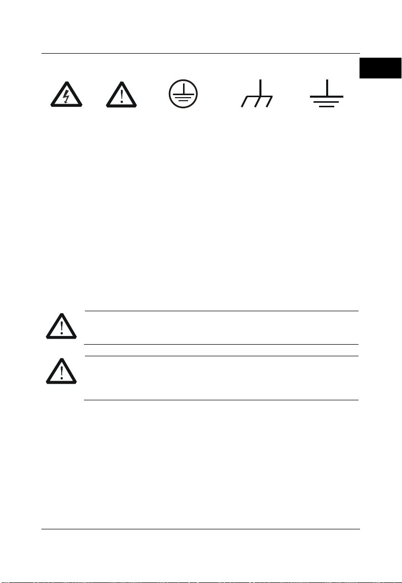
Hazardous
Voltage
Safety
Warning
Protective Earth
Terminal
Chassis Ground
Test Ground
CAUTION
To avoid damage to the instrument, do not expose it to caustic
liquids.
WARNING
To avoid short-circuit resulting from moisture or personal injuries,
ensure that the instrument is completely dry before connecting it
to the power supply.
Safety Symbols on the Product:
Care and Cleaning
Care
Do not store or leave the instrument where it may be exposed to direct sunlight
for long periods of time.
Cleaning
Clean the instrument regularly according to its operating conditions.
1. Disconnect the instrument from all power sources.
2. Clean the external surfaces of the instrument with a soft cloth dampened
with mild detergent or water. When cleaning the LCD, take care to avoid
scarifying it.
DP700 Quick Guide 3
Page 6

RIGOL
English
Tip
For the latest version of this manual, download it from RIGOL official
website (www.rigol.com).
Model
No. of Channels
Output Voltage/Current
DP711
1
30 V/5 A
DP712
1
50 V/3 A
Document Overview
This manual introduces some basic information that you should know when you
use the DP700 series power supply for the first time. It contains the following
contents: out-of-box inspection method, product overview, how to connect the
instrument to the AC power, procedures for carrying out the power-on
inspection and output inspection, as well as remote control overview.
Format Conventions in this Manual
Key
(1) The key on the front panel is denoted by the format of "Key Name (Bold)
+ Text Box" in the manual. For example, On/Off denotes the "On/Off"
key.
(2) Use the screen shot to indicate the key. For example, denotes the
Power key.
Content Conventions in this Manual
DP700 series programmable linear DC power supply includes the following
models. Unless otherwise specified, this manual takes DP711 as an example to
illustrate DP700 series power supply and its basic operation.
4 DP700 Quick Guide
Page 7

English
General Inspection
1. Inspect the packaging
If the packaging has been damaged, do not dispose the damaged
packaging or cushioning materials until the shipment has been checked
for completeness and has passed both electrical and mechanical tests.
The consigner or carrier shall be liable for the damage to the instrument
resulting from shipment. RIGOL would not be responsible for free
maintenance/rework or replacement of the instrument.
2. Inspect the instrument
In case of any mechanical damage, missing parts, or failure in passing the
electrical and mechanical tests, contact your RIGOL sales
representative.
3. Check the accessories
Please check the accessories according to the packing lists. If the
accessories are damaged or incomplete, please contact your RIGOL
sales representative.
RIGOL
DP700 Quick Guide 5
Page 8

RIGOL
English
V
mV
mA A
+
POWER
ON OFF
30V/5A
Number
1 2 3
4 5 6
7 8 9
Memory
System
OK
0
1. LCD
2. Function Keys
3. Output On/Off Key
4. Power Key
5. Output Terminals
6. Arrow Keys and
Confirmation Key
7. Knob
8. Num Keys and
Return Key
Product Overview
DP700 series power supply is a type of affordable programmable linear DC
power supply with high performance. With superb performance specifications,
pure and reliable output, and clear user interface, the DP700 series supports
timing output and trigger function, and provides a remote communication
interface, enabling you to meet your diversified test requirements.
For descriptions of the front panel, refer to Figure 1; for descriptions of the rear
panel, refer to Figure 2; and for descriptions of the main interface (display
screen), refer to Figure 3.
6 DP700 Quick Guide
Figure 1 Front Panel
Page 9

RIGOL
English
ACSELECTOR
100Vac 120Vac 220Vac 240Vac
100V T5A
120V 250Vac
220V T2.5A
240V 250Vac
FUSE RATING
RIGOLTECHNOLOGIES,INC.
MADEINCHINA
4. Output Setting
2. Actual Output
Status
5. System Status Icons
3. Help Information
1. Actual Output Mode
1. Input Power
Requirement
2. AC Power Supply
Connector
3. RS232 Interface
6. Fuse Rating
5. Fuse Cap
4. Air Outlet
7. AC Selector
Note: Pin 7 and Pin 8 of the RS232 interface are not used in remote communication. They are
used in the trigger function (optional).
DP700 Quick Guide 7
Figure 2 Rear Panel
Figure 3 Main Interface
Page 10

RIGOL
English
AC Input Power
AC Selector
100 Vac x (100% ± 10%), 50 Hz to 60 Hz
100Vac
120 Vac x (100% ± 10%), 50 Hz to 60 Hz
120Vac
120 Vac x (100% ± 10%), 50 Hz to 60 Hz
220Vac
240 Vac x (100% ± 10%) (max: 253 Vac), 50 Hz to 60 Hz
240Vac
WARNING
To avoid electric shock, ensure that the instrument is correctly
grounded.
Power-on Inspection
DP700 series power supply supports various specifications of AC input power.
When the DP700 series is connected with different AC power supplies, the AC
selector setting on the rear panel of the instrument is different, as shown in the
table below.
Table 1 AC Input Power Specification and AC Selector Setting
Please strictly follow the steps below to connect the instrument to the power
supply, and perform the power-on inspection and output inspection.
1. Check the input power
Ensure that the AC power to be connected to the instrument conforms to
the AC input power requirement specified in Table 1.
2. Check the AC selector
Ensure that the AC selector setting on the rear panel of the instrument
matches with the actual AC input power (refer to Table 1).
3. Check the fuse
When leaving the factory, the instrument has installed a fuse that
conforms to the local standard. When the input voltage is 100 Vac or 120
Vac, Fuse T5A is used; when the input voltage is 220 Vac or 240 Vac, Fuse
T2.5A is used.
4. Connect the AC power
Plug the specified power cord available in the accessories into the AC
power supply connector of the instrument, and then connect the
instrument to the properly grounded AC power.
8 DP700 Quick Guide
Page 11

English
5. Power on the instrument
Tip
After powering off the instrument, please wait for at least 2 s to power
it on again.
Press the Power key , and then the instrument is launched and
begins to perform the self-inspection. If the instrument passes the
self-inspection, the welcome interface is displayed; otherwise,
self-inspection failure information about corresponding items (including
the analog board, OVP, OCP, fan, and temperature) will be displayed.
6. Perform the output check
Perform the output check to ensure that the power supply can output the
rated values and properly respond to the operations on the front panel.
Note: Before checking the current output, you should complete the
voltage output check first.
Check the voltage output: verify the basic voltage functions without a
load.
(1) Press to power off the instrument.
(2) Ensure that no load is connected to the channel output terminals on
the front panel. Then, press to power on the instrument, and
check whether the voltage between the positive terminal (+) and
negative terminal (-) of the channel output is 0 V.
(3) Press On/Off to turn on the channel output.
At this time, the actual output status (actual
output voltage (V), actual output current (A),
and actual output power (W)) on the left
section of the interface is highlighted, and the
actual output mode (CV) is displayed.
(4) Set the output voltage to 0 V (For setting methods, refer to the
descriptions of the help information below the interface or
descriptions on Page 11.), and check whether the actual output
voltage displayed on the left section of the interface is approximately
0 V, the actual output current approximately 0 A. Set the output
voltage to 30 V (max. rating value), and check whether the actual
RIGOL
DP700 Quick Guide 9
Page 12

RIGOL
English
output voltage is approximately 30 V, the actual output current
approximately 0 A.
(5) Press On/Off to turn off the channel output.
Check the current output: verify the basic current functions with a
short across the power supply’s output.
(1) Connect a short across the positive terminal (+) and negative
terminal (-) of the channel output with an insulated test lead (18
AWG), and then press On/Off to turn on the channel output. At this
time, the actual output status (actual output voltage (V), actual
output current (A), and actual output power (W)) on the left section
of the interface is highlighted, and the actual output mode is
displayed. (Note that the actual output mode is determined by the
resistance of the test lead.)
(2) Set the output voltage to 2 V (For setting methods, refer to the
descriptions of the help information displayed below the interface or
refer to the descriptions on Page 11.) and ensure the output mode to
be CC.
(3) Set the output current to 0 A (For setting methods, refer to the
descriptions of the help information below the interface or
descriptions on Page 11.), and check whether the actual output
current displayed on the left section of the interface is approximately
0 A, the actual output voltage approximately 0 V. Set the output
current to 5 A (max. rating value), and check whether the actual
output current is approximately 5 A (the actual output voltage
indicates the voltage drop arising from the test lead).
(4) Press On/Off to turn off the channel output.
10 DP700 Quick Guide
Page 13
RIGOL
English
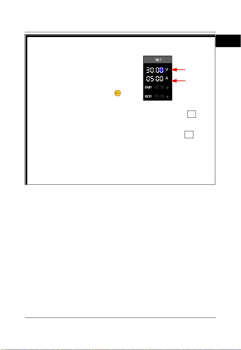
Setting Methods for Output Voltage/Output Current:
Method 1:
(1) Press the Up/Down arrow key to switch
the parameter focus to "Voltage
Setting Value" or "Current Setting
Value".
(2) Enter a value by using the num key.
While entering a value, press to
delete the unwanted character if
necessary.
(3) When setting the output voltage, press the Up arrow key or OK to set
the voltage unit to V; or press the Down arrow key to set the voltage
unit to mV. When setting the output current, press the Left arrow key to
set the current unit to mA; or press the Right arrow key or OK to set
the current unit to A.
Method 2:
(1) Press the Up/Down arrow key to switch the parameter focus to "Voltage
Setting Value" or "Current Setting Value".
(2) Press the Left/Right arrow key to move the cursor to a desired position.
(3) Rotate the knob to modify the value.
Current
Setting Value
Voltage
Setting Value
DP700 Quick Guide 11
Page 14

RIGOL
English
Remote Control
DP700 series power supply can be connected to the PC via the RS232 interface
to set up communication and realize remote control through the PC. The
remote control can be realized by using SCPI (Standard Commands for
Programmable Instruments) commands. DP700 series power supply supports
two ways of remote control: user-defined programming and PC software (e.g.
RIGOL Ultra Sigma).
When the instrument is in remote control, the icon is displayed on the user
interface. The keys on the front panel are locked (except , On/Off, and
). At this time, you can press to exit the remote mode.
More Product Information
1. Obtain the device information
Press System, and then press the Left/Right arrow key or use the knob to
select the "Info." tab. Then, you can obtain the device information,
including the device model, serial number, and software version.
2. Check the option installation
Press System, and then press the Left/Right arrow key or use the knob to
select the "Option" tab. Then, you can check the installation status of all
the options.
For more information about this instrument, refer to the relevant manuals by
logging in to the official website of RIGOL (www.rigol.com) to download them.
DP700 User's Guide
operation methods, remote control methods, possible failures and solutions in
using the DP700 series power supply, specifications, and order information;
DP700 Programming Guide
and programming instances of the instrument.
DP700 Datasheet
the instrument.
: introduces the functions of the instrument and the
: provides detailed descriptions of SCPI commands
: provides the main features and technical specifications of
12 DP700 Quick Guide
 Loading...