

Page 1
Page 2

Guaranty and Declaration
Copyright
© 2024 RIGOL TECHNOLOGIES CO., LTD. All Rights Reserved.
Trademark Information
RIGOL®is the trademark of RIGOL TECHNOLOGIES CO., LTD.
Notices
• RIGOL products are covered by P.R.C. and foreign patents, issued and pending.
• RIGOL reserves the right to modify or change parts of or all the specifications and pricing
policies at the company's sole decision.
• Information in this publication replaces all previously released materials.
• Information in this publication is subject to change without notice.
• RIGOL shall not be liable for either incidental or consequential losses in connection with the
furnishing, use, or performance of this manual, as well as any information contained.
• Any part of this document is forbidden to be copied, photocopied, or rearranged without prior
written approval of RIGOL.
Product Certification
RIGOL guarantees that this product conforms to the national and industrial standards in China as
well as the ISO9001:2015 standard and the ISO14001:2015 standard. Other international standard
conformance certifications are in progress.
Contact Us
If you have any problem or requirement when using our products or this manual, please contact
RIGOL.
E-mail: [email protected]
Website:
http://www.rigol.com
Page 3

Section Description Page
List of Figures................................................................................................................................IV
List of Tables............................................................................................................................... VIII
1 Safety Requirement .........................................................................................................1
1.1 General Safety Summary .................................................................................................................. 1
1.2 Safety Notices and Symbols ............................................................................................................ 3
1.3 Input Terminal Protection Limits .................................................................................................... 3
1.4 Measurement Category .....................................................................................................................4
1.5 Ventilation Requirement ................................................................................................................... 6
1.6 Working Environment ........................................................................................................................6
1.7 Care and Cleaning ............................................................................................................................... 7
1.8 Environmental Considerations ........................................................................................................8
2 Product Features .............................................................................................................. 9
3 Document Overview .....................................................................................................10
4 Quick Start ........................................................................................................................12
4.1 General Inspection ............................................................................................................................12
4.2 Appearance and Dimensions ........................................................................................................ 13
4.3 To Prepare for Use .............................................................................................................................14
4.3.1 To Adjust the Supporting Legs ........................................................................................14
4.3.2 To Connect to Power ...........................................................................................................14
4.3.3 Turn-on Checkout ................................................................................................................ 15
4.3.4 To Set the System Language ............................................................................................16
4.4 Product Overview ..............................................................................................................................16
4.4.1 Front Panel Overview ..........................................................................................................16
4.4.2 Rear Panel Overview ........................................................................................................... 20
4.4.3 User Interface Overview .................................................................................................... 21
4.5 Touch Screen Gestures .................................................................................................................... 24
4.5.1 Drag .......................................................................................................................................... 24
4.5.2 Tap ............................................................................................................................................. 24
4.6 Parameter Setting Method ............................................................................................................ 25
4.7 To Use the Security Lock .................................................................................................................29
5 Front Panel Operation ..................................................................................................31
5.1 To Set the Range ............................................................................................................................... 31
5.2 To Set the Measurement Rate ...................................................................................................... 33
Copyright ©RIGOL TECHNOLOGIES CO., LTD. All rights reserved. DM858 Series User Guide
I
Page 4

5.3 Basic Measurement Functions ......................................................................................................33
5.3.1 To Measure DC Voltage ......................................................................................................34
5.3.2 To Measure DC Current ......................................................................................................36
5.3.3 To Measure AC Voltage ......................................................................................................39
5.3.4 To Measure AC Current ......................................................................................................41
5.3.5 To Measure Resistance .......................................................................................................43
5.3.5.1 2WR Measurement ..............................................................................................43
5.3.5.2 4WR Measurement ..............................................................................................45
5.3.6 To Measure Capacitance ....................................................................................................47
5.3.7 To Test Continuity .................................................................................................................49
5.3.8 To Check Diode .....................................................................................................................51
5.3.9 To Measure Frequency/Period .........................................................................................53
5.3.9.1 Measure Frequency .............................................................................................53
5.3.9.2 Measure Period .....................................................................................................55
5.3.10 Any Sensor Measurement .................................................................................................57
5.3.10.1 To Measure the Temperature Sensor ............................................................ 59
5.3.10.2 To Measure User-defined Sensor ................................................................... 64
5.4 2ND Measurement ........................................................................................................................... 68
5.5 Preset Mode ........................................................................................................................................71
5.6 Math Operation ................................................................................................................................. 73
5.6.1 Statistics ...................................................................................................................................74
5.6.2 Limit .......................................................................................................................................... 75
5.6.3 dBm ...........................................................................................................................................77
5.6.4 dB ...............................................................................................................................................79
5.6.5 Relative .................................................................................................................................... 81
5.7 Graph Display ..................................................................................................................................... 82
5.7.1 Trend Graph ........................................................................................................................... 82
5.7.2 Histogram ............................................................................................................................... 84
5.7.3 Bar Chart ................................................................................................................................. 89
5.8 Trigger ................................................................................................................................................... 92
5.8.1 Auto Trig ..................................................................................................................................93
5.8.2 Single ........................................................................................................................................96
5.8.3 External Trigger .....................................................................................................................98
5.9 Screen Image ....................................................................................................................................100
5.10 Customized Menu .......................................................................................................................... 101
5.11 System Utility Function Setting ..................................................................................................102
5.11.1 NET Setting .......................................................................................................................... 103
DM858 Series User Guide
II
Copyright ©RIGOL TECHNOLOGIES CO., LTD. All rights reserved.
Page 5

5.11.2 LXI Setting ............................................................................................................................ 105
5.11.3 Basic System Settings .......................................................................................................106
5.11.4 Instrument Information ................................................................................................... 107
5.11.5 Self-check ............................................................................................................................. 108
5.12 To Store and Load ...........................................................................................................................110
5.12.1 To Save a File .......................................................................................................................111
5.12.2 To Load a File .......................................................................................................................115
5.12.3 Upgrade ................................................................................................................................ 116
5.12.4 Disk Management ............................................................................................................. 117
5.13 To Use the Built-in Help System ................................................................................................ 118
6 Troubleshooting ...........................................................................................................120
7 Remote Control ............................................................................................................121
8 Measurement Tutorial ................................................................................................122
8.1 True RMS AC Measurements ...................................................................................................... 122
8.2 Crest Factor Errors (non-sinusoidal inputs) ........................................................................... 122
8.3 Loading Errors (AC Volts) ............................................................................................................. 123
8.4 Application of the Analog Filter ................................................................................................ 124
9 Specifications ................................................................................................................127
9.1 Specifications ................................................................................................................................... 127
10 Appendix ........................................................................................................................ 138
10.1 Appendix A: Options and Accessories .................................................................................... 138
10.2 Appendix B: Warranty ................................................................................................................... 138
Copyright ©RIGOL TECHNOLOGIES CO., LTD. All rights reserved. DM858 Series User Guide
III
Page 6

List of Figures
Figure 4.1 Front View ..............................................................................................................13
Figure 4.2 Side View ................................................................................................................13
Figure 4.3 Adjusting the Supporting Legs ......................................................................14
Figure 4.4 Connect to Power ............................................................................................... 14
Figure 4.5 DM858 Front Panel .............................................................................................16
Figure 4.6 Rear Panel ..............................................................................................................20
Figure 4.7 User Interface (Single Display) ....................................................................... 21
Figure 4.8 User Interface (Dual Display) .......................................................................... 22
Figure 4.9 Drag Gesture .........................................................................................................24
Figure 4.10 Tap Gesture .........................................................................................................25
Figure 4.11 English Input Interface ....................................................................................25
Figure 4.12 Chinese Input Interface .................................................................................. 27
Figure 4.13 Numeric Keypad Input Interface .................................................................28
Figure 4.14 To Use the Security Lock ................................................................................30
Figure 5.1 Range and Rate Selection Keys ......................................................................32
Figure 5.2 Range Selection Menu ......................................................................................32
Figure 5.3 DC Voltage Measurement Interface .............................................................35
Figure 5.4 DC Voltage Measurement Connection Diagram ......................................35
Figure 5.5 DC Current Measurement Interface ............................................................. 37
Figure 5.6 DC Current Measurement Connection Diagram ......................................38
Figure 5.7 AC Voltage Measurement Interface ............................................................. 39
Figure 5.8 AC Voltage Measurement Connection Diagram ......................................40
Figure 5.9 AC Current Measurement Interface ..............................................................41
Figure 5.10 AC Current Measurement Connection Diagram ....................................42
Figure 5.11 2WR Measurement Interface ........................................................................43
Figure 5.12 2WR Measurement Connection Diagram ................................................44
Figure 5.13 4WR Measurement Interface ........................................................................46
DM858 Series User Guide
IV
Copyright ©RIGOL TECHNOLOGIES CO., LTD. All rights reserved.
Page 7

Figure 5.14 4WR Measurement Connection Diagram ................................................46
Figure 5.15 Capacitance Measurement Setting Interface ..........................................48
Figure 5.16 Capacitance Measurement Connection Diagram ................................. 48
Figure 5.17 Continuity Test Interface ................................................................................50
Figure 5.18 Continuity Test Connection Diagram .........................................................50
Figure 5.19 Diode Measurement Interface .....................................................................52
Figure 5.20 Diode Measurement Connection Diagram ..............................................52
Figure 5.21 Frequency Measurement Interface ............................................................ 54
Figure 5.22 Frequency Measurement Connection Diagram .....................................54
Figure 5.23 Period Measurement Interface .................................................................... 56
Figure 5.24 Period Measurement Connection Diagram .............................................56
Figure 5.25 Voltage, Resistance, TC, Frequency Sensor Connection Method .....58
Figure 5.26 Current Sensor Connection Method ..........................................................58
Figure 5.27 Sensor Measurement Interface ....................................................................59
Figure 5.28 Temperature Sensor Setting Interface .......................................................60
Figure 5.29 RTD Temperature Sensor Setting Interface ............................................. 62
Figure 5.30 Therm Temperature Sensor Setting Interface .........................................63
Figure 5.31 User-defined Sensor Setting Interface ......................................................64
Figure 5.32 User-defined Sensor Name Setting ............................................................65
Figure 5.33 Reference Value Setting Table ......................................................................66
Figure 5.34 Reference Value Setting .................................................................................67
Figure 5.35 Customize the Sensor .....................................................................................67
Figure 5.36 2ND Measurement Setting Interface .........................................................68
Figure 5.37 Main and Secondary Display Areas ............................................................69
Figure 5.38 Preset Interface ................................................................................................. 72
Figure 5.39 Preset Setting Interface ..................................................................................72
Figure 5.40 Math Operation Setting .................................................................................73
Figure 5.41 Statistic Parameter Setting ............................................................................74
Figure 5.42 Statistics Operation Result ............................................................................ 75
Copyright ©RIGOL TECHNOLOGIES CO., LTD. All rights reserved. DM858 Series User Guide
V
Page 8

Figure 5.43 Limit Parameter Setting ..................................................................................76
Figure 5.44 Limit Operation ................................................................................................. 77
Figure 5.45 dBm Parameter Setting Interface ................................................................78
Figure 5.46 dBm Operation Results ...................................................................................79
Figure 5.47 dB Operation Parameter Setting .................................................................79
Figure 5.48 dB Operation Results .......................................................................................80
Figure 5.49 Relative operation ............................................................................................81
Figure 5.50 Graph Display .....................................................................................................82
Figure 5.51 Manual Setting Menu ..................................................................................... 83
Figure 5.52 Trend Graph of DCV Measurement ............................................................84
Figure 5.53 Graph Display Interface ..................................................................................85
Figure 5.54 Histogram Setting Interface ......................................................................... 86
Figure 5.55 Histogram Manual Setting ............................................................................87
Figure 5.56 Histogram of DCV Measurement ................................................................88
Figure 5.57 Display Interface ............................................................................................... 89
Figure 5.58 BarChart Setting Interface .............................................................................90
Figure 5.59 Manual Setting of Bar Chart .........................................................................91
Figure 5.60 Bar Chart of DCV Measurement ..................................................................92
Figure 5.61 Trigger Parameter Setting ..............................................................................93
Figure 5.62 Auto Trigger Setting Interface ..................................................................... 94
Figure 5.63 Enable the Hold function ...............................................................................96
Figure 5.64 Single Trigger Parameter Setting ................................................................ 97
Figure 5.65 External Trigger Parameter Setting .............................................................98
Figure 5.66 Storage Interface ............................................................................................101
Figure 5.67 Customized Menu Setting Interface ........................................................102
Figure 5.68 System Utility Function Setting Interface ..............................................103
Figure 5.69 NET Setting ...................................................................................................... 104
Figure 5.70 LXI Setting .........................................................................................................105
Figure 5.71 System Settings Interface ............................................................................106
DM858 Series User Guide
VI
Copyright ©RIGOL TECHNOLOGIES CO., LTD. All rights reserved.
Page 9

Figure 5.72 Basic Information of the Instrument ....................................................... 108
Figure 5.73 Self-check Interface .......................................................................................109
Figure 5.74 Keyboard Test ..................................................................................................109
Figure 5.75 Touch Screen Test ...........................................................................................110
Figure 5.76 Screen Test ........................................................................................................110
Figure 5.77 Storage Interface ............................................................................................111
Figure 5.78 Data Saving ......................................................................................................113
Figure 5.79 Setup Saving ....................................................................................................114
Figure 5.80 Load Setting Menu ........................................................................................115
Figure 5.81 Histogram Display of the Loaded Data File .......................................... 116
Figure 5.82 Upgrade Menu ................................................................................................117
Figure 5.83 Disk Management Interface .......................................................................117
Copyright ©RIGOL TECHNOLOGIES CO., LTD. All rights reserved. DM858 Series User Guide
VII
Page 10

List of Tables
Table 4.1 Power Adaptor Specifications ...........................................................................15
Table 5.2 DC Voltage Measurement Parameter Setting .............................................36
Table 5.3 DC Current Measurement Parameter Setting ............................................. 38
Table 5.4 AC Voltage Measurement Parameter Setting ............................................. 40
Table 5.5 AC Current Measurement Parameter Setting ..............................................42
Table 5.6 2WR Measurement Parameter Setting ..........................................................44
Table 5.7 4WR Measurement Parameter ......................................................................... 46
Table 5.8 Capacitance Measurement Parameter Settings ......................................... 49
Table 5.9 Continuity Test Parameter Settings ................................................................ 51
Table 5.10 Frequency Measurement Settings ................................................................54
Table 5.11 Period Measurement Parameter Setting ....................................................56
Table 5.12 Meas. Value Setting Range ..............................................................................66
Table 5.13 2ND Measurement Parameter Setting ........................................................68
Table 5.14 Basic Measurement Types and 2ND Measurement Types ................... 69
Table 5.15 Description of Math Operations ....................................................................73
Table 5.16 Statistic Parameter Setting ..............................................................................75
Table 5.17 Limit Parameter Setting ....................................................................................76
Table 5.18 dBm Parameter Setting .................................................................................... 78
Table 5.19 dB Parameter Setting ........................................................................................ 80
Table 5.20 Relative Value Setting Range ..........................................................................81
Table 5.21 Max. Number of Samples Displayed in the Histogram .........................88
Table 5.22 Trigger Setting Menu ........................................................................................ 93
Table 5.23 Auto Trigger Menu .............................................................................................94
Table 5.24 Single Trigger Parameter Setting .................................................................. 97
Table 5.25 External Trigger Parameter Setting ...............................................................99
Table 5.26 NET Setting Menu ............................................................................................104
Table 5.27 LXI Setting Menu ..............................................................................................105
DM858 Series User Guide
VIII
Copyright ©RIGOL TECHNOLOGIES CO., LTD. All rights reserved.
Page 11

Table 5.28 System Setting Menu ......................................................................................107
Table 5.29 Types of Files to be Saved .............................................................................111
Table 8.1 True RMS AC Measurement of Sine, Triangle and Square Waves ..... 122
Table 8.2 Input Resistance at Various Frequencies .................................................... 123
Table 8.3 Analog Filter Error in DCV Measurement ...................................................125
Table 8.4 Analog Filter Error in DCI Measurement .................................................... 125
Copyright ©RIGOL TECHNOLOGIES CO., LTD. All rights reserved. DM858 Series User Guide
IX
Page 12

DM858 Series User Guide
X
Copyright ©RIGOL TECHNOLOGIES CO., LTD. All rights reserved.
Page 13

Safety Requirement
1
Safety Requirement
1.1 General Safety Summary
Please review the following safety precautions carefully before putting the instrument
into operation so as to avoid any personal injury or damage to the instrument and
any product connected to it. To prevent potential hazards, please follow the
instructions specified in this manual to use the instrument properly.
• Use Proper Power Cord.
Only the exclusive power cord designed for the instrument and authorized for
use within the destination country could be used.
• Ground the Instrument.
The power adaptor of this instrument is a three-pin power plug, but the
instrument housing is not connected to the earth lead of the three-pin power
plug. To avoid electric shock, use the ground lead provided in accessories to
connect the instrument housing to an electrical ground before performing
measurements.
• Observe All Terminal Ratings.
To avoid fire or shock hazard, observe all ratings and markers on the instrument
and check your manual for more information about ratings before connecting
the instrument.
• Use Proper Overvoltage Protection.
Ensure that no overvoltage (such as that caused by a bolt of lightning) can reach
the product. Otherwise, the operator might be exposed to the danger of an
electric shock.
• Do Not Operate without Covers.
Do not operate the instrument with covers or panels removed.
• Do Not Insert Objects into the Air Outlet.
Do not insert objects into the air outlet, as doing so may cause damage to the
instrument.
• Use the Proper Fuse.
Please use the specified fuses.
• Avoid Circuit or Wire Exposure.
Do not touch exposed junctions and components when the instrument is
powered on.
• Do Not Operate with Suspected Failures.
Copyright ©RIGOL TECHNOLOGIES CO., LTD. All rights reserved. DM858 Series User Guide
1
Page 14
Safety Requirement
• Provide Adequate Ventilation.
• Do Not Operate in Wet Conditions.
• Do Not Operate in an Explosive Atmosphere.
If you suspect that any damage may occur to the instrument, have RIGOL
authorized personnel before further operations. Any maintenance, adjustment or
replacement especially to circuits or accessories must be performed by RIGOL
authorized personnel.
Inadequate ventilation may cause an increase of temperature in the instrument,
which would cause damage to the instrument. So please keep the instrument
well ventilated and inspect the air outlet and the fan regularly.
To avoid short circuit inside the instrument or electric shock, never operate the
instrument in a humid environment.
To avoid personal injuries or damage to the instrument, never operate the
instrument in an explosive atmosphere.
• Keep Instrument Surfaces Clean and Dry.
To avoid dust or moisture from affecting the performance of the instrument,
keep the surfaces of the instrument clean and dry.
• Prevent Electrostatic Impact.
Operate the instrument in an electrostatic discharge protective environment to
avoid damage induced by static discharges. Always ground both the internal and
external conductors of cables to release static before making connections.
• Handle with Caution.
Please handle with care during transportation to avoid damage to keys, knobs,
interfaces, and other parts on the panels.
• Only for Measurements within the Specified Measurement Categories.
The measurements are allowed at CAT I 1000 V/CAT II 300 V only. To avoid
damage to the instrument and electric shock, do not make measurements out of
the voltage range or at CAT III/CAT IV.
WARNING
Equipment meeting Class A requirements may not offer adequate protection to broadcast
services within residential environment.
DM858 Series User Guide
2
Copyright ©RIGOL TECHNOLOGIES CO., LTD. All rights reserved.
Page 15
1.2 Safety Notices and Symbols
Safety Notices in this Manual:
WARNING
Indicates a potentially hazardous situation or practice which, if not avoided, will result in
serious injury or death.
CAUTION
Indicates a potentially hazardous situation or practice which, if not avoided, could result
in damage to the product or loss of important data.
Safety Notices on the Product:
• DANGER
Safety Requirement
It calls attention to an operation, if not correctly performed, could result in injury
or hazard immediately.
• WARNING
It calls attention to an operation, if not correctly performed, could result in
potential injury or hazard.
• CAUTION
It calls attention to an operation, if not correctly performed, could result in
damage to the product or other devices connected to the product.
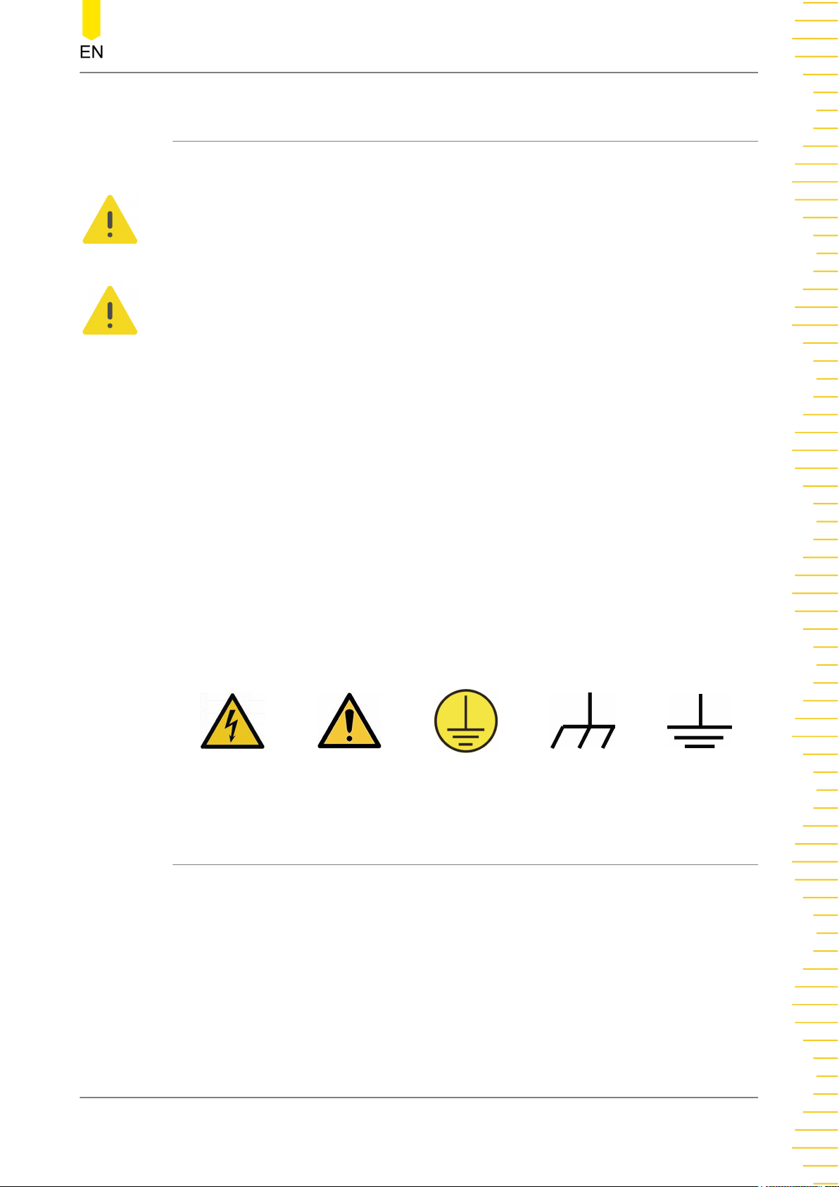
Safety Symbols on the Product:
Hazardous
Voltage
Safety Warning Protective Earth
Terminal
1.3 Input Terminal Protection Limits
Chassis Ground Test Ground
Protection Limits are defined for the input terminals:
Main Input (HI and LO) Terminals
The HI and LO input terminals are used for voltage, resistance, capacitance, continuity,
frequency (period), and diode test measurements. The following two Protection Limits
are defined for these terminals:
1. HI to LO Protection Limit: 1000 VDC or 750 VAC, which is also the maximum
voltage measurement. This limit can also be expressed as 1000 Vpk maximum.
Copyright ©RIGOL TECHNOLOGIES CO., LTD. All rights reserved. DM858 Series User Guide
3
Page 16
Safety Requirement
2. LO to Ground Protection Limit. The LO input terminal can safely "float" a maximum
of 500 Vpk relative to the ground.
The protection limit for HI terminal is a maximum of 1000 Vpk relative to the ground.
Therefore, the sum of the "float" voltage and the measured voltage cannot exceed
1000 Vpk.
Sense (HI Sense and LO Sense) Terminal
HI Sense and LO Sense terminals are used only for four-wire resistance
measurements. The following two Protection Limits are defined for these terminals:
1. HI Sense to LO Sense Protection Limit. HI Sense to LO Sense Protection Limit: 200
Vpk.
2. LO Sense to LO Protection Limit. LO Sense to LO Protection Limit: 2 Vpk.
Current Input (I) Terminal
The I and LO terminals are used for current measurements. The I terminal has a
protection limit of 10 A(DM858)/3.15 A(DM858E) maximum current flowing through
the terminal by the front-panel current input fuse.
CAUTION
The current input terminal will be at approximately the same voltage as the LO terminal
unless the current input fuse is blown. To maintain protection, replace this fuse only with
a fuse of the specified type and rating.
1.4 Measurement Category
Measurement Category
CAT I 1000 V/CAT II 300 V
WARNING
To avoid the danger of electric shock, do not make measurements out of the voltage
range or at CAT III/CAT IV (such as measuring AC motors, motor protectors, frequency
converters, and inverters).
WARNING
For CAT II, the input terminal can be connected to the main circuit (up to 300 VAC). To
avoid electric shock, do not connect the input terminal to the main circuit with a line
voltage above 300 VAC rms. See
DM858 Series User Guide
4
IEC Measurement Category II
Copyright ©RIGOL TECHNOLOGIES CO., LTD. All rights reserved.
in this section.
Page 17
Safety Requirement
IEC Measurement Category II
To protect against the danger of electric shock, DM858/DM858E Digital Multimeter
provides overvoltage protection for line-voltage mains connections meeting both of
the following conditions:
1. The HI and LO input terminals are connected to the mains under Measurement
Category II conditions, defined below.
2. The mains are limited to a maximum line voltage of 300 VAC.
IEC Measurement Category II includes electrical devices connected to mains at an
outlet on a branch circuit. Such devices include most small appliances, test
equipment, and other devices that plug into a branch outlet or socket. DM858/
DM858E may be used to make measurements with the HI and LO inputs connected to
mains in such devices (up to 300 VAC), or to the branch outlet itself.
WARNING
To avoid electric shock, DM858/DM858E may not be used with its HI and LO inputs
connected to mains in permanently installed electrical devices such as the main circuit-
breaker panel, sub-panel disconnect boxes, or permanently wired motors. Such devices
and circuits are subject to overvoltages that may exceed the protection limits of the
DM858/DM858E.
CAUTION
Voltages above 300 VAC may be measured only in circuits that are isolated from mains.
However, transient overvoltages are also present on circuits that are isolated from mains.
DM858/DM858E is designed to safely withstand occasional transient overvoltage up to
2500 Vpk. Do not use this equipment to measure circuits where transient overvoltage
could exceed this level.
Measurement Category Definitions
• Measurement Category I (CAT I) is for measurements performed on circuits not
directly connected to MAINS. Examples are measurements on batteries,
electronic devices (especially laptops), and circuits not derived from MAINS,
especially protected (internal) MAINS derived circuits.
• Measurement Category II (CAT II) is for measurements performed on circuits
directly connected to low voltage installation. Examples are measurements on
household appliances, portable tools and similar equipment.
• Measurement Category III (CAT III) is for measurements performed in the
building installation. Examples are measurements on distribution boards, circuitbreakers, wiring (including cables, bus-bars, junction boxes, switches and socketoutlets) in the fixed installation, and equipment for industrial use and some
other equipment. For example, stationary motors with permanent connection to
a fixed installation.
Copyright ©RIGOL TECHNOLOGIES CO., LTD. All rights reserved. DM858 Series User Guide
5
Page 18
Safety Requirement
• Measurement Category IV (CAT IV) is for measurements performed at the
source of a low-voltage installation. Examples are electricity meters and
measurements on primary overcurrent protection devices and ripple control
units.
1.5 Ventilation Requirement
This instrument uses the natural convection for heat dissipation. When using the
instrument in a bench-top or rack setting, provide at least 10 cm clearance beside,
above, and behind the instrument for adequate ventilation.
CAUTION
Inadequate ventilation may cause an increase of temperature in the instrument, which
would cause damage to the instrument. So please keep the instrument well ventilated and
inspect the air outlet regularly.
1.6 Working Environment
Temperature
Operating: 0℃ to +50℃
Non-operating: -20℃ to +70℃
Humidity
≤80% RH, 40℃, without condensation
WARNING
To avoid short circuit inside the instrument or electric shock, never operate the
instrument in a humid environment.
Altitude
Below 3 km
Protection Level Against Electric Shock
ESD ±8kV
Installation (Overvoltage) Category
This product is powered by mains conforming to installation (overvoltage) category II.
WARNING
Ensure that no overvoltage (such as that caused by a bolt of lightning) can reach the
product. Otherwise, the operator might be exposed to the danger of an electric shock.
DM858 Series User Guide
6
Copyright ©RIGOL TECHNOLOGIES CO., LTD. All rights reserved.
Page 19
Safety Requirement
Installation (Overvoltage) Category Definitions
Installation (overvoltage) category I refers to signal level which is applicable to
equipment measurement terminals connected to the source circuit. Among these
terminals, precautions are done to limit the transient voltage to a low level.
Installation (overvoltage) category II refers to the local power distribution level which
is applicable to equipment connected to the AC line (AC power).
Pollution Degree
Pollution Degree 2
Pollution Degree Definition
• Pollution Degree 1: No pollution or only dry, nonconductive pollution occurs.
The pollution has no effect. For example, a clean room or air-conditioned office
environment.
• Pollution Degree 2: Normally only nonconductive pollution occurs. Temporary
conductivity caused by condensation is to be expected. For example, indoor
environment.
• Pollution Degree 3: Conductive pollution or dry nonconductive pollution that
becomes conductive due to condensation occurs. For example, sheltered
outdoor environment.
• Pollution Degree 4: The pollution generates persistent conductivity caused by
conductive dust, rain, or snow. For example, outdoor areas.
Safety Class
Class 2
1.7 Care and Cleaning
Care
Do not store or leave the instrument where it may be exposed to direct sunlight for
long periods of time.
Cleaning
Clean the instrument regularly according to its operating conditions.
1. Disconnect the instrument from all power sources.
2. Clean the external surfaces of the instrument with a soft cloth dampened with mild
detergent or water. Avoid having any water or other objects into the chassis via the
heat dissipation hole. When cleaning the LCD, take care to avoid scarifying it.
CAUTION
To avoid damage to the instrument, do not expose it to caustic liquids.
Copyright ©RIGOL TECHNOLOGIES CO., LTD. All rights reserved. DM858 Series User Guide
7
Page 20
Safety Requirement
WARNING
To avoid short-circuit resulting from moisture or personal injuries, ensure that the
instrument is completely dry before connecting it to the power supply.
1.8 Environmental Considerations
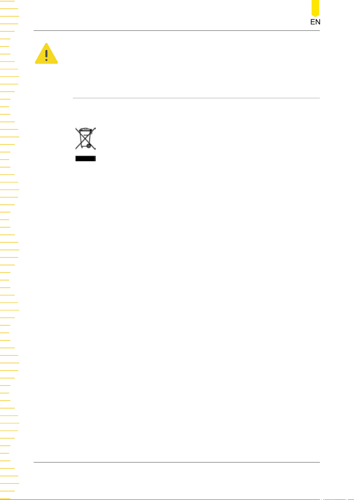
The following symbol indicates that this product complies with the WEEE Directive
2012/19/EU.
The equipment may contain substances that could be harmful to the environment or
human health. To avoid the release of such substances into the environment and
avoid harm to human health, we recommend you to recycle this product
appropriately to ensure that most materials are reused or recycled properly. Please
contact your local authorities for disposal or recycling information.
You can click on the following link
https://int.rigol.com/services/services/declaration
to download the latest version of the RoHS&WEEE certification file.
DM858 Series User Guide
8
Copyright ©RIGOL TECHNOLOGIES CO., LTD. All rights reserved.
Page 21
Product Features
2
Product Features
Product Features
• Max. reading rate: 125 readings/s
• Up to 500,000 points logging memory to record and analyze more data
• 5½-digit reading resolution (120,000 counts)
• True-RMS AC Voltage and AC Current measuring
• Built-in 10 groups of data storage and 10 groups of setup storage
• Strong Math functions, supporting various application protocols
• 7'' color touch screen, displaying dual-measurement results concurrently
• Type-C interface for power charge; compact in size, freeing up your bench
space
• Standard USB and LAN interfaces, supporting Web Control
DM858 series benchtop digital multimeter provides a highly cost-effective test tool
for engineers. It features 5.5-digit resolution, max. 125 readings/s, data logging
memory of 500,000 points, and 0.03% DCV accuracy (1 year). It provides 11
measurement functions for input signals, 5 Math operations, and 3 graphical display
types, satisfying what most experiments and tests require of a multimeter. The 7''
touch screen allows a clear view on measurement results. Its provides USB and LAN
interfaces (standard) as well as the Web Control function for you to control the
instrument directly, bringing smoother interaction. It is equipped with a Type-C
interface for power charge. In addition, it has a compact size and supports the
attachment to a bracket, saving valuable bench space for engineers.
Copyright ©RIGOL TECHNOLOGIES CO., LTD. All rights reserved. DM858 Series User Guide
9
Page 22
Document Overview
3
Document Overview
This manual gives you a quick overview of the front and rear panel, user interface as
well as basic operation methods of DM858 series digital multimeter.
TIP
For the latest version of this manual, download it from RIGOL official website (
www.rigol.com
Publication Number
UGC11103-1110
Software Version
Software upgrade might change or add product features. Please acquire the latest
version of the manual from RIGOL website or contact RIGOL to upgrade the software.
Format Conventions in this Manual
1. Key
).
http://
The front panel key is denoted by the menu key icon. For example,
indicates the "Trig" key.
2. Menu
The menu item is denoted by the format of "Menu Name (Bold) + Character
Shading" in the manual. For example,
item. You can click or tap
3. Operation Procedures
The next step of the operation is denoted by ">" in the manual. For example,
> Storage indicates first clicking or tapping and then clicking or tapping
Storage.
4. Connector
The front/rear panel connector is denoted by "Brackets + Connector Name (Bold)",
for example, [EXT TRIG].
Content Conventions in this Manual
Measure to access the "Measure" menu.
Measure indicates the "Measure" menu
DM858 series digital multimeter includes DM858 and DM858E models. The table
below shows the main differences between the two models. Their operation methods
are the same. Unless otherwise specified, this manual takes DM858 as an example to
illustrate the basic operation methods of DM858 series.
DM858 Series User Guide
10
Copyright ©RIGOL TECHNOLOGIES CO., LTD. All rights reserved.
Page 23
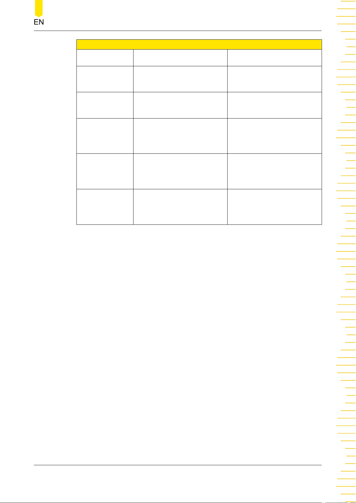
Specifications for Different Models
DM858 DM858E
Document Overview
DCV Accuracy (1
year)
Max. Reading
Rate
No. of Points in
Data Logging
Memory
Current
Measurement
Range
Capacitance
Measurement
Range
0.030% 0.060%
125 readings/s 80 readings/s
500,000 data points 20,000 data points
100 μA to 10 A 100 μA to 3 A
1 nF to 10 mF 1 nF to 1 mF
Copyright ©RIGOL TECHNOLOGIES CO., LTD. All rights reserved. DM858 Series User Guide
11
Page 24

Quick Start
4
Quick Start
4.1 General Inspection
1. Inspect the packaging
If the packaging has been damaged, do not dispose the damaged packaging or
cushioning materials until the shipment has been checked for completeness and
has passed both electrical and mechanical tests.
The consigner or carrier shall be liable for the damage to the instrument resulting
from shipment. RIGOL would not be responsible for free maintenance/rework or
replacement of the instrument.
2. Inspect the instrument
In case of any mechanical damage, missing parts, or failure in passing the electrical
and mechanical tests, contact your RIGOL sales representative.
3. Check the accessories
Please check the accessories according to the packing lists. If the accessories are
damaged or incomplete, please contact your RIGOL sales representative.
Recommended Calibration Interval
RIGOL suggests that the instrument should be calibrated every 12 months.
DM858 Series User Guide
12
Copyright ©RIGOL TECHNOLOGIES CO., LTD. All rights reserved.
Page 25
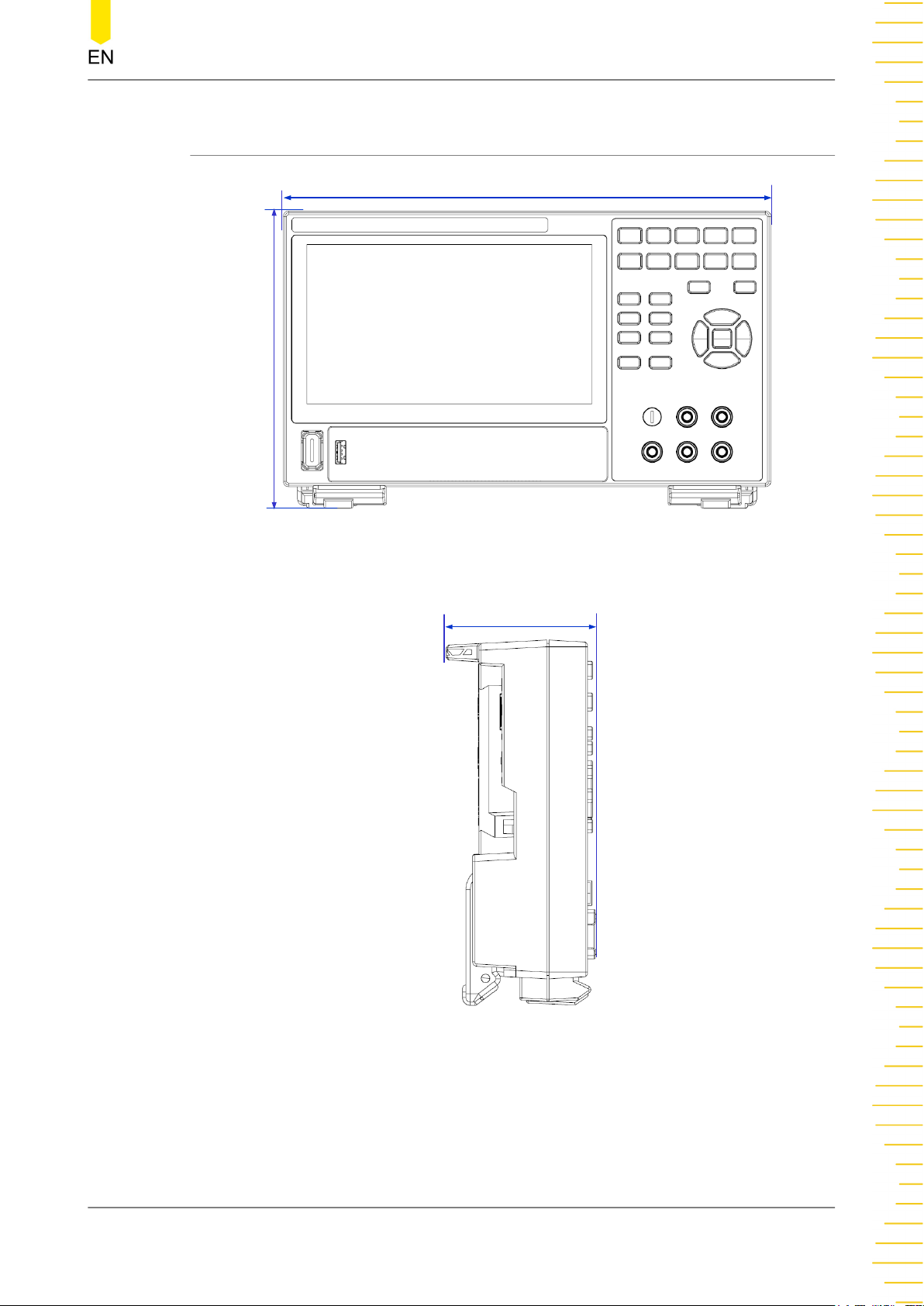
4.2 Appearance and Dimensions
266 mm
165 mm
Quick Start
Figure 4.1 Front View
80 mm
Figure 4.2 Side View
Copyright ©RIGOL TECHNOLOGIES CO., LTD. All rights reserved. DM858 Series User Guide
13
Page 26
Quick Start
4.3 To Prepare for Use
4.3.1 To Adjust the Supporting Legs
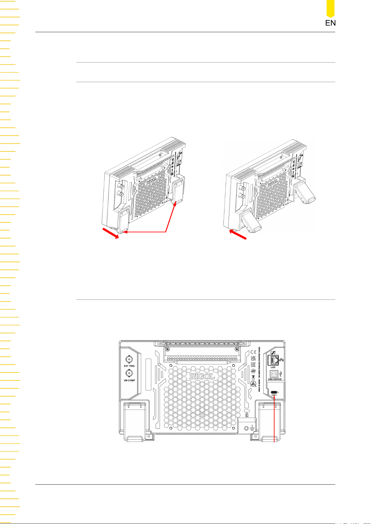
Adjust the supporting legs properly to use them as stands to tilt the multimeter
upwards for stable placement of the multimeter as well as better operation and
observation. You can also fold the supporting legs when the instrument is not in use
for easier storage or shipment, as shown in the figure below.
(a) Unfold the supporting legs
Figure 4.3 Adjusting the Supporting Legs
4.3.2 To Connect to Power
The power requirements of the multimeter are DC, 12 V, 3 A. Please use the power
adaptor provided in the accessories to connect the multimeter to the AC power
source (100 V to 240 V, 50 Hz to 60 Hz), as shown in the figure below.
Supporting
Legs
(b) Fold the supporting legs
DM858 Series User Guide
14
Power Cord Connector
Figure 4.4 Connect to Power
Copyright ©RIGOL TECHNOLOGIES CO., LTD. All rights reserved.
Page 27
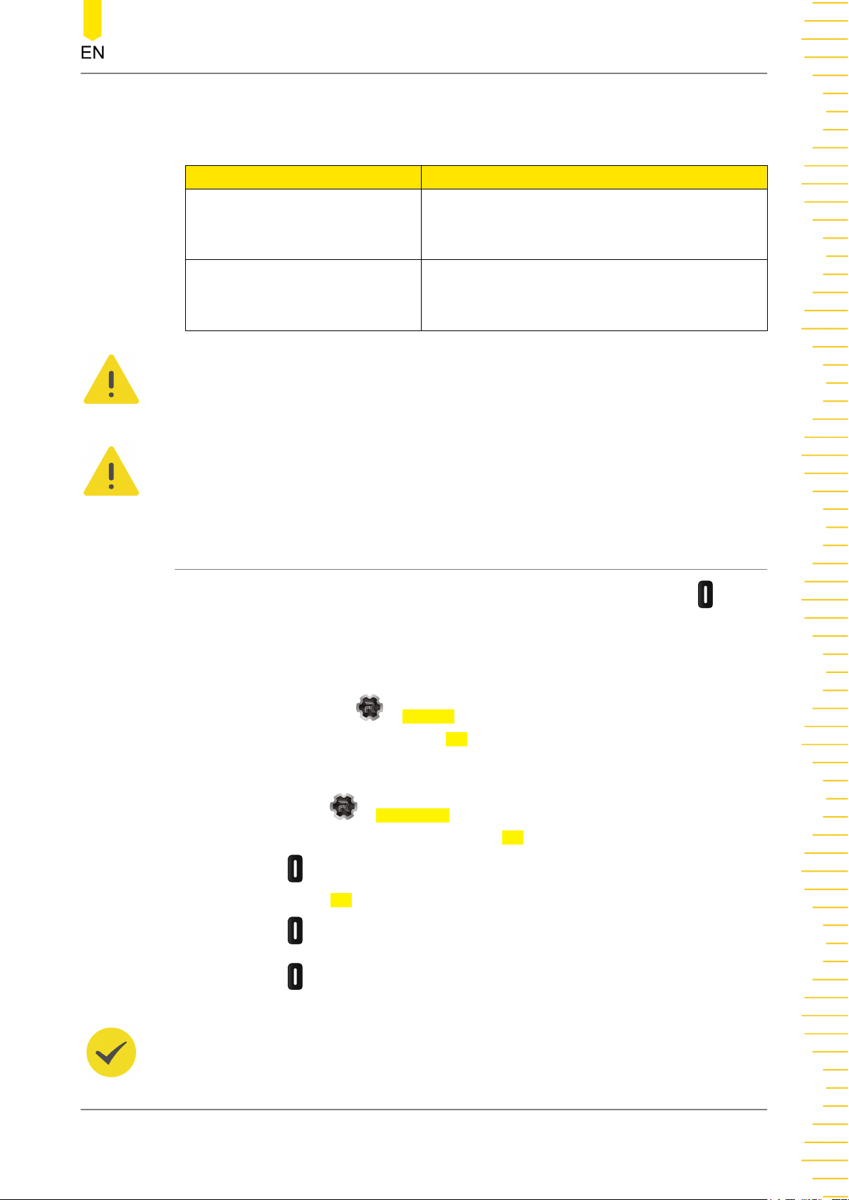
Table 4.1 Power Adaptor Specifications
Model Ratings
Quick Start
PA-1650-58LT
(LITE-ON TECHNOLOGY, INC)
ADP-65KE B
(DELTA ELECTRONICS, INC)
CAUTION
The power adaptor provided in accessories can only be used to power RIGOL instruments.
Do not use it for mobile phone and other devices.
WARNING
To avoid electric shock, please ensure that the instrument is correctly grounded.
4.3.3 Turn-on Checkout
After the instrument is connected to the power source, press the power key at the
lower-left corner of the front panel to power on the instrument. During the start-up
process, the instrument performs a series of self-tests. After the self-test, the splash
screen is displayed.
Input: AC, 100 V to 240 V, 50 Hz to 60 Hz, 1.6 A
Output: 3 A@5 V/9 V/12 V/15 V, 3.25 A@20 V
Input: AC, 100 V to 240 V, 50 Hz to 60 Hz, 1.7 A
Output: 3 A@5 V/9 V/12 V/15 V, 3.25 A@20 V
• Reboot: Click or tap > Reboot. Then a prompt message "Are you sure to
reboot?" is displayed. Click or tap
OK to restart the instrument.
• Shutdown:
- Click or tap > Shutdown. Then a prompt message "Are you sure to
shutdown?" is displayed. Click or tap OK to shut down the instrument.
- Press and a prompt message "Are you sure to shutdown?" is displayed.
Click or tap
OK to shut down the instrument.
- Press twice to shut down the instrument.
- Press for three seconds to shut down the instrument.
TIP
Copyright ©RIGOL TECHNOLOGIES CO., LTD. All rights reserved. DM858 Series User Guide
15
Page 28
Quick Start
You can also click or tap > System > Settings and set the "Power Status" to "ON". The
instrument powers on once connected to power.
4.3.4 To Set the System Language
This product supports multiple languages. You can click or tap > System >
Settings > Language to select the system language.
4.4 Product Overview
Unless otherwise specified, this chapter takes DM858 as an example to introduce the
appearance and dimensions, front and rear panels, and user interface of DM858 and
DM858E.
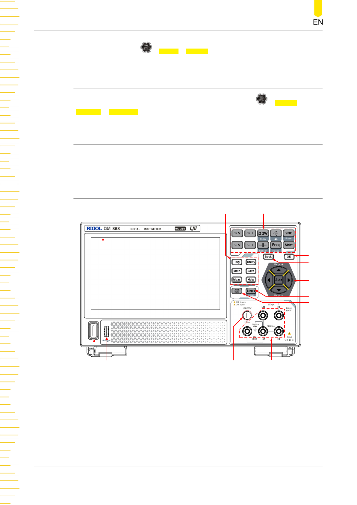
4.4.1 Front Panel Overview
1
12
11
2
3
4
5
6
7
8
10
9
1. 7-inch Capacitive Touch Screen
Displays the menu and parameter settings of the currently enabled function,
system state, prompt messages, and other information.
2. Auxiliary Function Keys
DM858 Series User Guide
16
Figure 4.5 DM858 Front Panel
Copyright ©RIGOL TECHNOLOGIES CO., LTD. All rights reserved.
Page 29
Quick Start
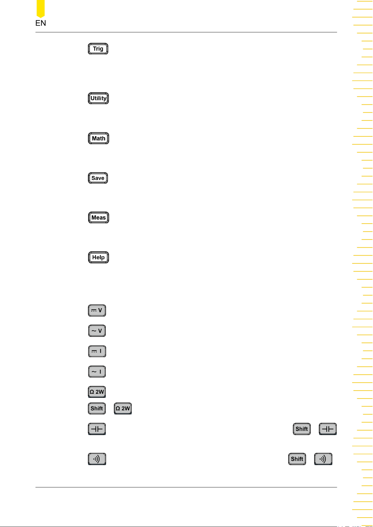
: indicates the trigger setting key. Press this key to open the trigger setting
menu. You can set the trigger mode (auto, single, and external), enable the reading
hold function, set the number of samples per trigger, set the delay time prior to
reading, the edge of the trigger input signal, and trigger output.
: indicates the system utility function setting. Press this key to open the
system utility setting menu. You can set the basic system settings and view the
system information.
: indicates the math operation key. Press this key to open the math
operation menu. You can perform the math operation (limit, statistics, dBm, and
dB) on the measurement results.
: indicates the storage operation key. Press this key to open the storage
setting key. You can save, load, upgrade the file; perform the disk management
operation to copy, cut, or delete files.
: indicates the measurement setting key. Press this key to open the
measurement parameter setting menu. You can configure the parameters for the
current measurement item.
: indicates the Help key. Press this key to enter the Help documentation.
You can get its help information by clicking on the link for the introduction of the
specified function.
3. Measurement Function Keys
: Press this key to enable the DC voltage (DCV) measurement.
: Press this key to enable the AC voltage (ACV) measurement.
: Press this key to enable the DC current (DCI) measurement.
: Press this key to enable the AC current (ACI) measurement.
: Press this key to enable the 2-wire resistance (Ω 2W) measurement. Press
> to enable the 4-wire resistance (Ω 4W) measurement.
: Press this key to enable the capacitance measurement. Press >
to enable any sensor measurement.
: Press this key to enable the continuity measurement. Press >
to enable the diode measurement.
Copyright ©RIGOL TECHNOLOGIES CO., LTD. All rights reserved. DM858 Series User Guide
17
Page 30
Quick Start
: Press this key to enable the frequency measurement. Press >
to enable the period measurement.
: Press this key and then press the specified secondary function to enable
the secondary measurement function. Press > to preset the current
instrument configuration, save it, and apply the configuration.
Under some of the measurement function keys are printed with the
specified alternative function names or labels. To enable the specified function
displayed under the key, first press , and then press the specified function
key. For example, as shown on the front panel, 4-wire resistance measurement
label is displayed under the 2-wire resistance measurement key. To enable the 4-
wire impedance measurement, first press
, and then press .
4. Confirmation Key
: Press this key to confirm the current parameter settings.
5. Back Key
: Press this key to exit the current operation or close the current dialog box
(if exists).
6. Range Selection and Arrow Keys
: Press this key to enable the auto range.
: indicates the Up/Down arrow keys.
Press the Up/Down arrow keys to increase/decrease the range manually.
In measuring DCV, DCI, ACV, ACI, Frequency or Period, you can use the Left/Right
arrow keys to increase/decrease the measurement speed.
7. Single/Local Key
unless you press it once again. To make the instrument to switch to the local mode,
press the Shift key first, and then press this key.
8. Auto Trigger/Reading Hold Key
DM858 Series User Guide
18
: indicates the Left/Right arrow keys.
: Press Single to trigger one single acquisition and will not trigger again
Copyright ©RIGOL TECHNOLOGIES CO., LTD. All rights reserved.
Page 31
Quick Start
: Press this key to switch between auto trigger and readings hold functions.
- Run: The key is always illuminated and remains the auto-trig state unchanged.
In this state, the instrument continues acquiring data at the specified speed
based on the current settings.
- Hold: The key is blinking constantly and the acquisition stops. The
measurement data are displayed on the screen.
9. Signal Input Terminals
The signals (devices) under test are input to the instrument via these terminals. The
measurement connection methods are different for different objects under test.
10. Current Input Fuse
The front-panel current input fuse allows a max. of 10 A(DM858)/3.15 A(DM858E)
protection limit. Once the input current exceeds 13.5 A(DM858)/4.05 A(DM858E),
the fuse blows out.
11. USB HOST Interface
Allows to connect the USB storage device (FAT32 or NTFS format) or the mouse.
- USB storage device: imports or exports data (e.g. software update, waveforms,
setups, or screenshot files).
- Mouse: It can be connected to the instrument to realize remote control.
12. Power Key
Powers on or off the instrument.
Copyright ©RIGOL TECHNOLOGIES CO., LTD. All rights reserved. DM858 Series User Guide
19
Page 32
Quick Start
4.4.2 Rear Panel Overview
2
1
8
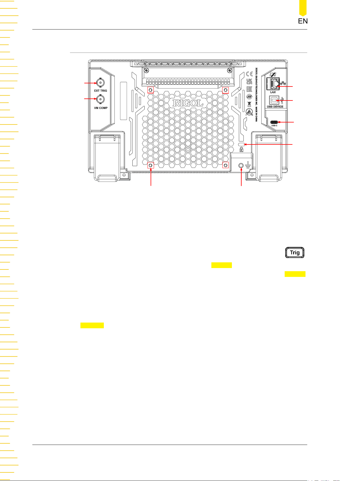
Figure 4.6 Rear Panel
1. VM COMP Output Interface
The multimeter outputs a pulse via [VM Comp] connector after each
7
3
4
5
6
measurement when VM output is enabled. To enable the VM output, press
on the front panel (you can also click or tap the Trigger label at the bottom of the
screen to enter the trigger setting interface), then click or tap "ON" for the Output
menu to enable the VMC output.
2. External Trigger Input Interface
Triggers the multimeter by connecting a pulse via the [EXT TRIG] connector after
external trigger is selected. To enable the external trigger, click or tap to select
External.
3. LAN Interface
Connects the instrument to network via this interface. The instrument is in
compliance with the standards specified in
used to set up a test system with other standard devices. Then you can use the
Web Control to send the SCPI commands to control the instrument.
4. USB DEVICE Interface
Connects the instrument to the PC via this interface. Then you can use the PC
software to send the SCPI commands or use the user-defined programming to
control the instrument.
LXI Device Specification 2011
. It can be
5. USB Type-C Power Interface
DM858 Series User Guide
20
Copyright ©RIGOL TECHNOLOGIES CO., LTD. All rights reserved.
Page 33
The power requirements of the multimeter are DC, 12 V, 3 A. Please use the power
adaptor provided in the accessories to connect the multimeter to the AC power
source (100 V to 240 V, 50 Hz to 60 Hz).
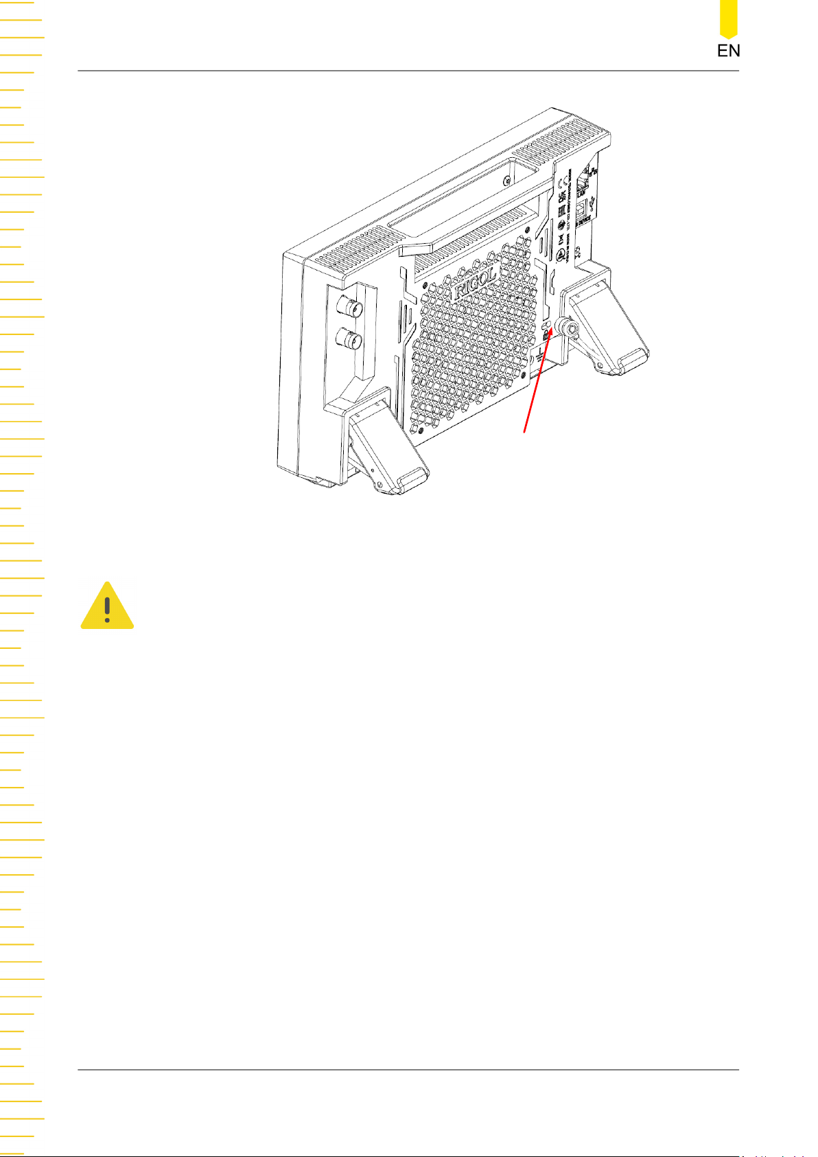
6. Security Lock Hole
You can lock the instrument to a fixed location by using the security lock (please
purchase it by yourself) via the lock hole.
7. Ground Terminal
Connects with the instrument chassis and ground lead (power cord ground
terminal), which is in the grounded state.
8. Mounting Screw Holes (VESA 100 x 100)
Mounts the multimeter to the bracket with the screws.
4.4.3 User Interface Overview
Quick Start
3
4
5
6
7
8
9 10
2
1
13
12
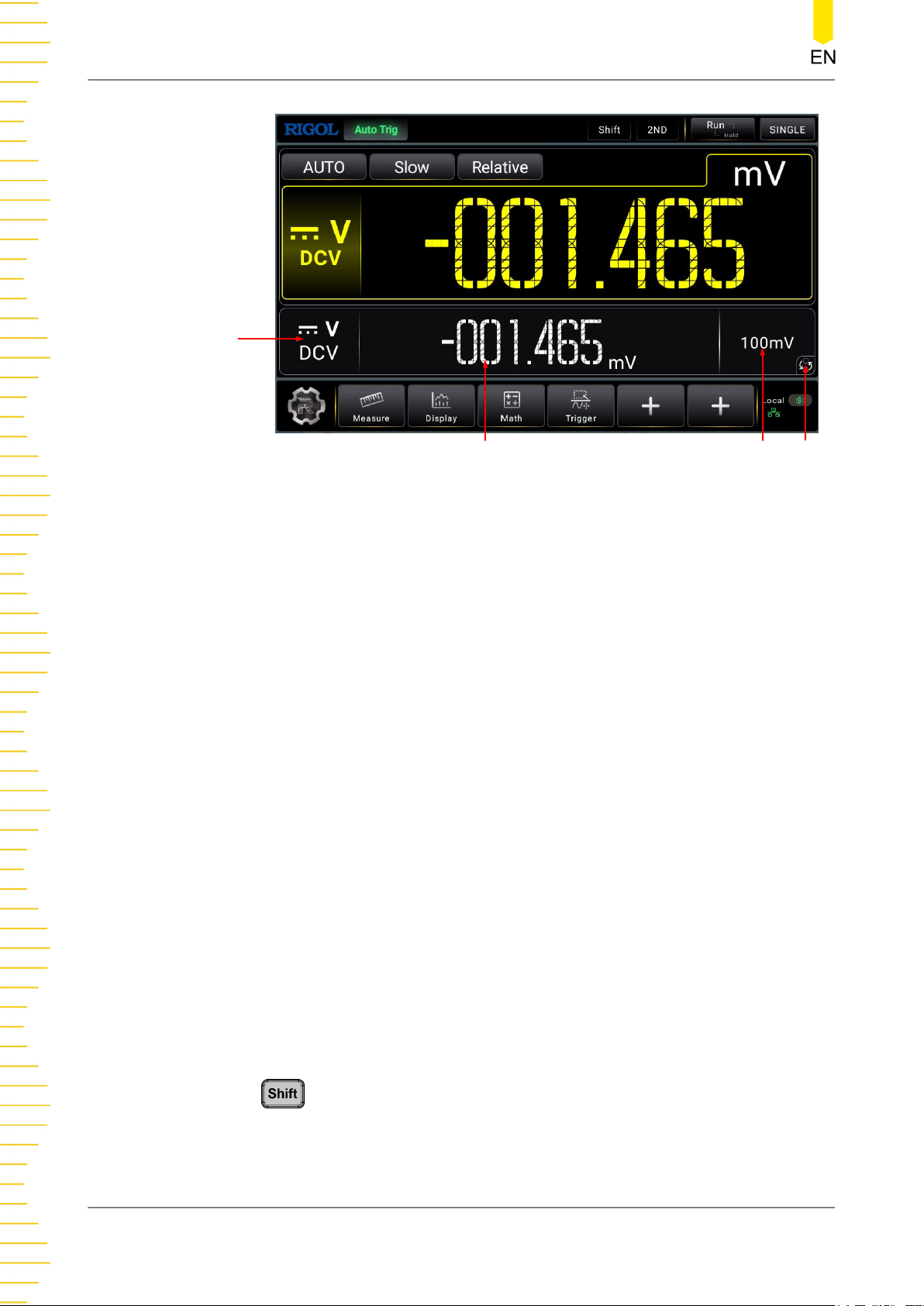
Figure 4.7 User Interface (Single Display)
11
Copyright ©RIGOL TECHNOLOGIES CO., LTD. All rights reserved. DM858 Series User Guide
21
Page 34
Quick Start
17
16
15
14
Figure 4.8 User Interface (Dual Display)
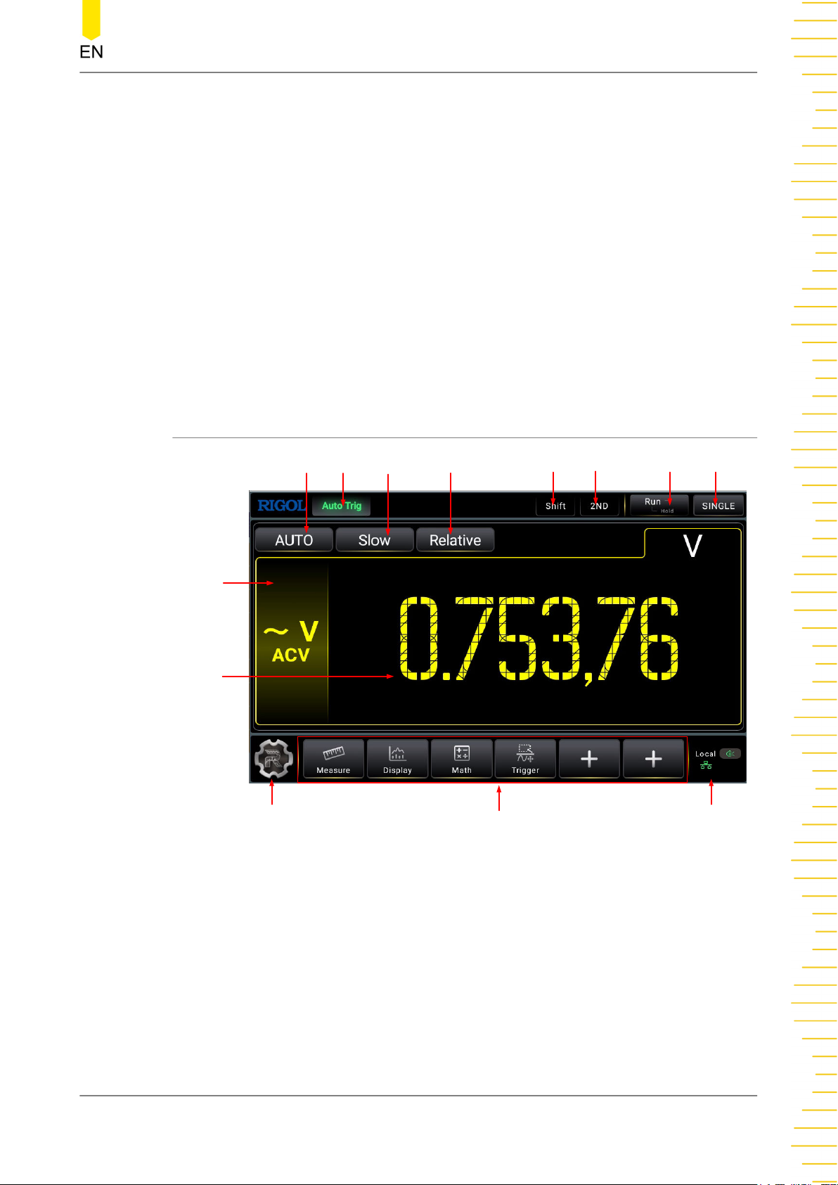
1. Main Measurement Result Display
Displays the measurement result of the current main measurement item.
2. Main Measurement Item
Displays the main measurement item. Click or tap the label, the main measurement
items are displayed. Click or tap to select the specified main measurement item to
be displayed in the main display area.
3. Main Measurement Range Selection
Displays the measurement range for the specified main measurement item.
4. Operating Status
Displays the current operating status of the instrument. It can be Auto Trig, Single
Trig, Ext Trig, Hold, or Stop.
5. Measurement Speed Selection
Displays the current measurement speed. Click or tap the label to select Slow,
Medium, or Fast from the drop-down list.
6. "Relative" Tab
Click or tap the tab to enable or disable the relative operation.
7. "Shift" Tab
Press
highlighted.
8. "2ND" Tab
DM858 Series User Guide
22
on the front panel to enable the Shift key. The "Shift" tab is
Copyright ©RIGOL TECHNOLOGIES CO., LTD. All rights reserved.
Page 35
Quick Start
When you press the 2ND key on the front panel, the "2ND" tab is highlighted.
9. "Run/Hold" Tab
Click or tap the "Run/Hold" tab to switch the status from Run to Hold. You can also
press Run/Hold on the front panel to switch the status from Run to Hold.
10. "Single" Tab
Click or tap the "Single" tab to initiate one single trigger. You can also press Single
on the front panel to initiate one single trigger.
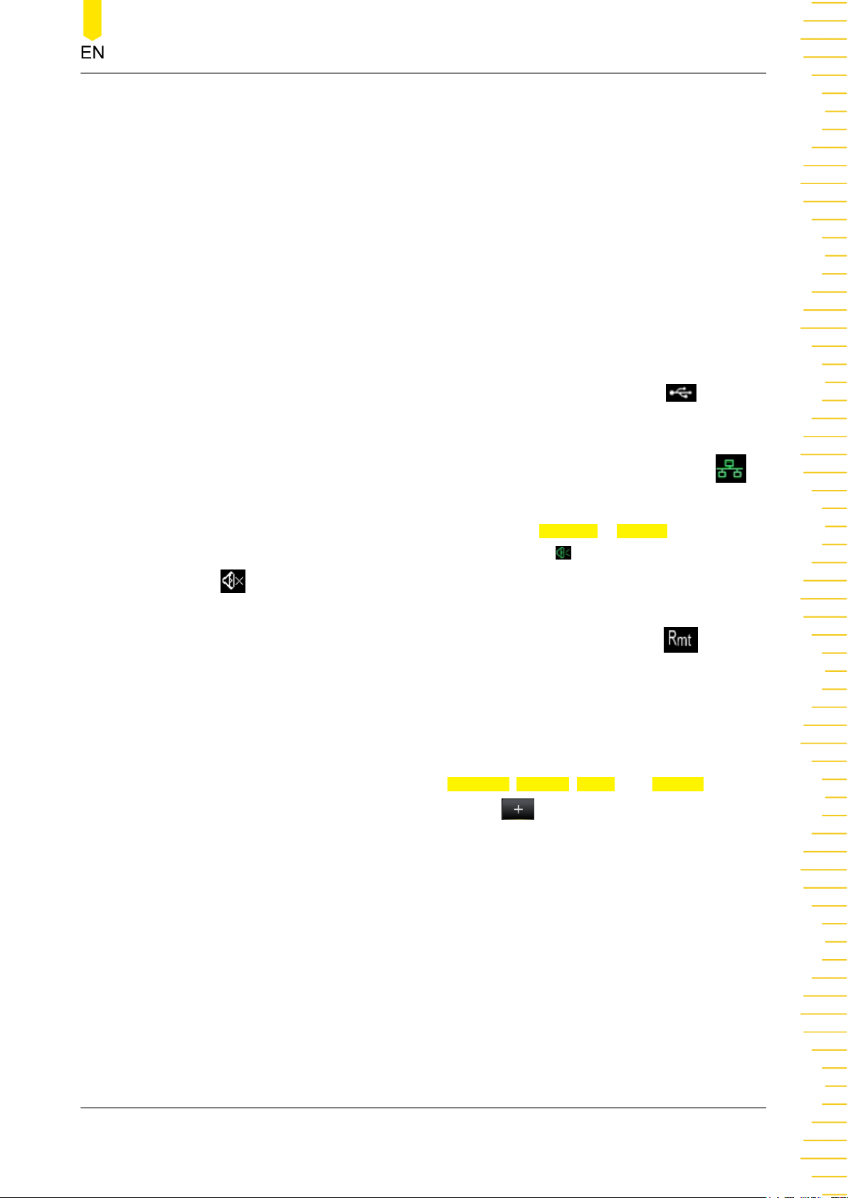
11. Notification Area
Displays the USB storage device icon, LAN connection, sound icon, and remote
control icon. Click or tap the area, the system setting menu is displayed.
-
USB storage device icon: When a USB storage device is detected,
displayed.
-
LAN connection icon: When the LAN interface is successfully connected, is
displayed.
- Sound icon: In the "System" menu, click or tap
Settings > Beeper to enable or
disable the sound. When the sound is turned on, will be displayed; when off,
will be displayed. Clicking or tapping the sound icon can also enable or
disable the sound.
- Remote control icon: When you control the instrument remotely,
displayed.
- Time: When you enable to display the time information, the system time is
displayed.
12. Shortcut Menus
Provides four fixed shortcut menus (
Measure, Display, Math, and Trigger) and
will be
will be
two customized menus. You can click or tap to customize the shortcut menu
that you want to add here.
13. Function Navigation Icon
Click or tap the icon to enter the function navigation menu. Click or tap the
desired menu to enter the specified menu setting interface.
14. Main-Secondary Measurement Item Switchover Icon
When you enable the 2ND measurement, click or tap this icon to switch between
the main measurement item and the secondary (2ND) measurement item.
15. Secondary (2ND) Measurement Range
Displays the measurement range of the 2ND measurement item when the 2ND
measurement is enabled.
Copyright ©RIGOL TECHNOLOGIES CO., LTD. All rights reserved. DM858 Series User Guide
23
Page 36
Quick Start
16. Secondary (2ND) Measurement Result Display
Displays the measurement result of the 2ND measurement item when the 2ND
measurement is enabled.
17. Secondary (2ND) Measurement Item
Displays the secondary (2ND) measurement item. When you enable the 2ND
measurement, click or tap the label, then the 2ND measurement menu is
displayed.
4.5 Touch Screen Gestures
The instrument's capacitive touch screen makes operation and configuration easy and
flexible. It features great convenience, high flexibility, and great sensitivity. The actions
supported by the touch screen controls include dragging and tapping.
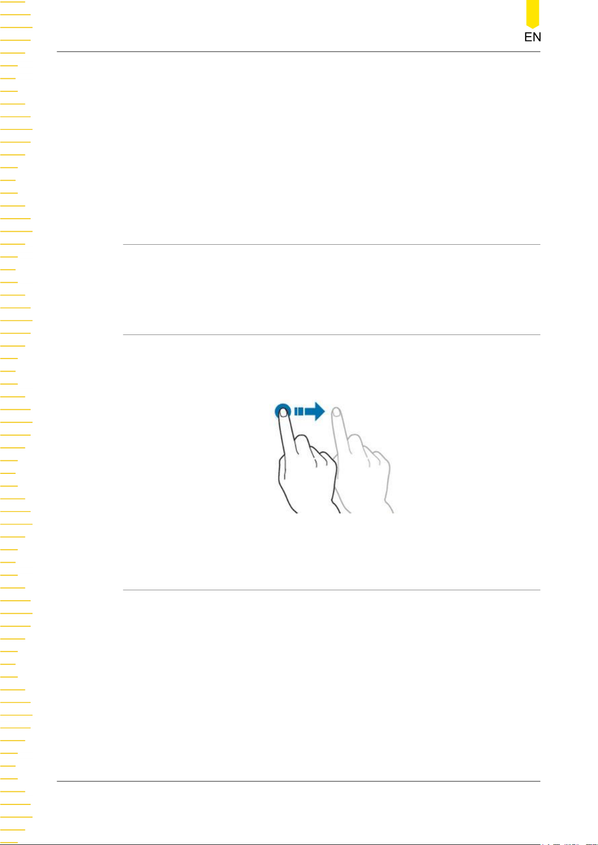
4.5.1 Drag
Use one finger to select the object, and then drag the object to a destination place, as
shown in
position (e.g. numeric keypad).
4.5.2 Tap
Use one finger to tap the symbol or characters on the screen slightly, as shown in
Figure 4.10
Figure 4.9
. With the Tap gesture, you can perform the following operations:
. You can also drag the window controls to change the window
Figure 4.9 Drag Gesture
• Tap the menu displayed on the screen to operate on the menu.
• Tap the function navigation icon at the lower-left corner of the touch screen to
• Tap the displayed numeric keypad to set the parameters.
• Tap the virtual keypad to set the filename.
DM858 Series User Guide
24
enable the function navigation.
Copyright ©RIGOL TECHNOLOGIES CO., LTD. All rights reserved.
Page 37
Quick Start
• Tap the close button at the upper-right corner of the message box to close the
prompt window.
• Tap other windows on the touch screen and operate on the windows.
Figure 4.10 Tap Gesture
4.6 Parameter Setting Method
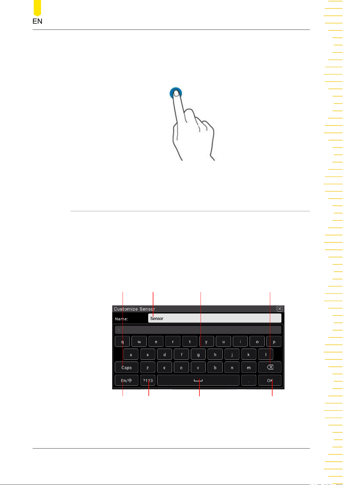
Tap the input field of the parameter, then a virtual keypad is displayed. Input the
values to complete the parameter settings.
Input Chinese and English
You can use the Chinese/English input method to input a name.
• Input English
Capital
Switch
Input
Area
Letters Delete
Input
Method
Number
Switch
Space
Confirm
Figure 4.11 English Input Interface
Copyright ©RIGOL TECHNOLOGIES CO., LTD. All rights reserved. DM858 Series User Guide
25
Page 38
Quick Start
1. Select English input method
First check the input method type. If it shows "En/中", then go to Step 2; if it
shows "中/En", click or tap the input method switchover key to switch to "En/
中" (English input method).
2. Clear the name input area
If there is no character in the "Name Input Area", please go to the next step. If
there are characters in the "Name Input Area", click or tap the Backspace key
to delete all the characters from the "Name Input Area" in order.
3. Input the upper-case letter
If you want to input an upper-case letter, first use the Caps key to switch
between the upper-case and lower-case mode. If the Caps key is selected,
input the upper-case letter with the virtual keypad. If not, first click or tap the
Caps key to ensure it is selected, then input the upper-case letter. All the input
letters will be displayed in the "Name Input Area".
Input the lower-case letter
4.
Refer to the operation specified in the previous step. If the Caps key is not
selected, directly input the lower-case letter.
5. Input numbers or symbols
If the letter keypad is displayed, you need to click or tap the numeric
switchover key to switch to the numeric keypad, and input numbers or
symbols with the numeric keypad. All the input letters will be displayed in the
"Name Input Area".
6. Modify or delete the unwanted characters that have been input
During the name input process, you can modify or delete the unwanted
character if necessary. To delete the characters that have been input, click or
tap the Backspace key in the virtual keypad to delete the characters. To
modify the input characters, delete the unwanted characters and input the
desired characters again.
You can directly move the cursor to the character to be modified or deleted,
delete the desired character or input the new characters after deleting the
unwanted character.
• Input Chinese Characters
DM858 Series User Guide
26
7. Confirm the input
After completing the input operation, click or tap OK.
Copyright ©RIGOL TECHNOLOGIES CO., LTD. All rights reserved.
Page 39
Quick Start
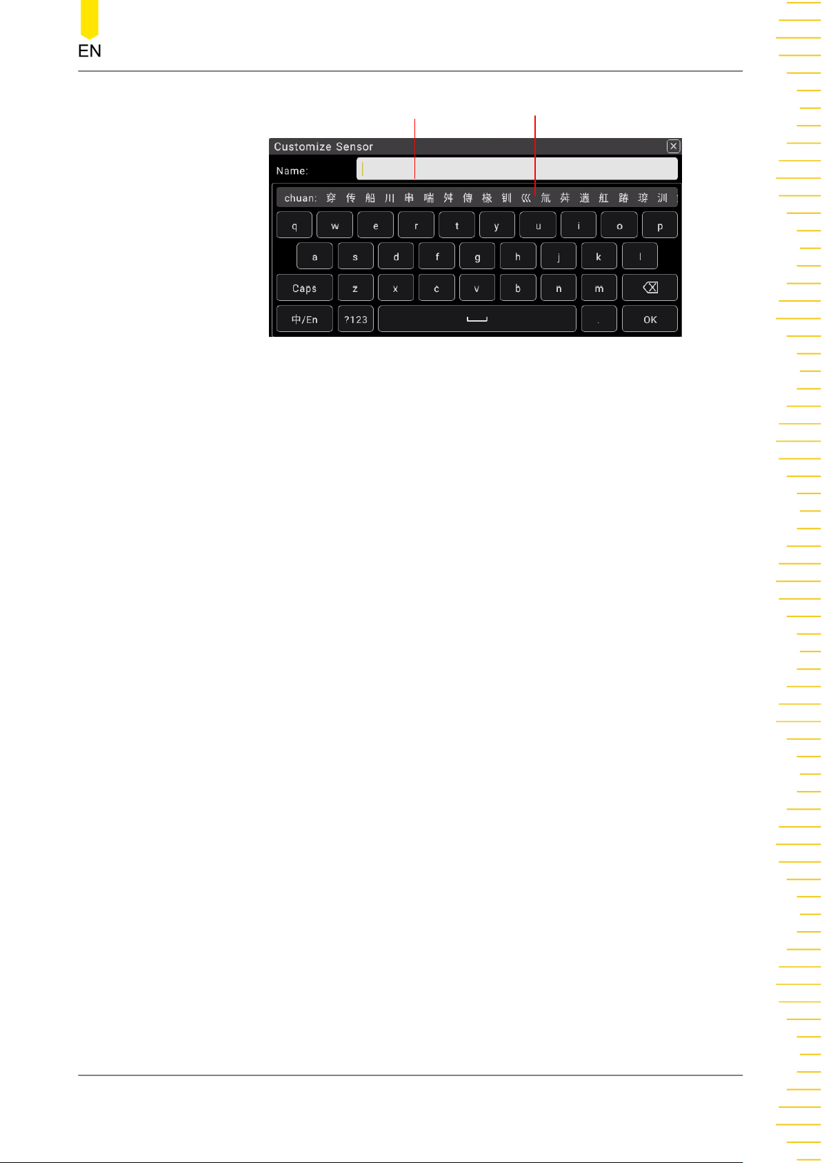
Input Area
Chinese character selection area
Figure 4.12 Chinese Input Interface
1. Select Chinese input method
First check the Chinese and English Characters type. If it shows "中/En", then
go to Step 2; if it shows "En/中", click or tap the input method switchover key
to switch to "中/En" (Chinese input method).
2. Clear the name input area
If there is no character in the "Name Input Area", please go to the next step. If
there are characters in the "Name Input Area", click or tap the Backspace key
to delete all the characters denoted "Name Input Area" in order.
3. Input Chinese characters
Click or tap the characters in the virtual keypad to input Pinyin into the input
area, then the characters to be selected will be displayed in the Chinese
character selection area. Slide to view more Chinese characters for you to
choose. Select the desired Chinese character, and then the selected character
will be displayed in the input area.
4. Modify or delete the unwanted characters that have been input
During the name input process, you can modify or delete the unwanted
character if necessary. To delete the characters that have been input, click or
tap the Backspace key in the virtual keypad to delete the characters. To
modify the input characters, delete the unwanted characters and input the
desired characters again.
5. Confirm the input
After completing the input operation, click or tap OK.
Input a Value
When setting or modifying a parameter, use the pop-up numeric keypad to input an
appropriate value.
Copyright ©RIGOL TECHNOLOGIES CO., LTD. All rights reserved. DM858 Series User Guide
27
Page 40
Quick Start
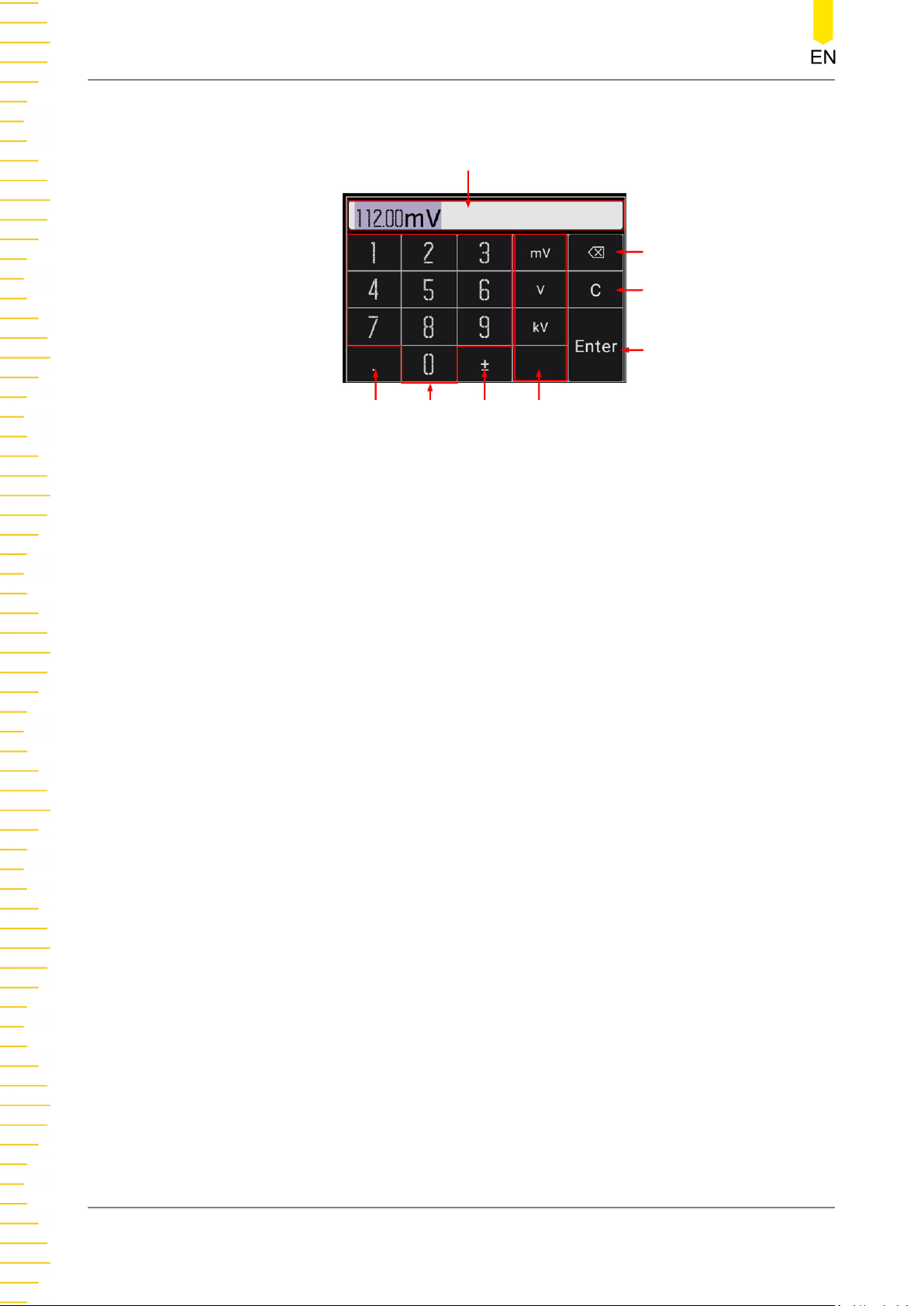
• Click or tap the value or unit in the virtual numeric keypad to complete the input.
Input Area
Delete
Clear
Enter
Decimal
Point
Number
Key
Plus or
minus sign
Unit(Optional)
Figure 4.13 Numeric Keypad Input Interface
After you input all the values and select the desired units, the virtual numeric keypad
is turned off automatically. This indicates that you have completed parameter setting.
In virtual the numeric keypad, you can perform the following operation:
1. Input Area
Click or tap the desired number and the desired value is input in this area.
2. Number Key
There are 10 numbers in the numeric key area. Click or tap the number to input the
desired value.
3. Decimal Point
- To input a decimal number less than 1, input the decimal point first and then
add a number.
- To input a real number with decimals, input an real number first and then add a
- The dot can be added to the specified position when you input a value that is
- It is not allowed to input several decimal points.
4. Plus or minus sign (±)
DM858 Series User Guide
28
decimal point. The number of zero digits is automatically added after the
decimal point according to the rules of the specified parameter.
not an integer.
Copyright ©RIGOL TECHNOLOGIES CO., LTD. All rights reserved.
Page 41

Quick Start
Your first click or tap of the sign will input a minus (-) sign, the second time of click
or tap of it will input a plus sign, but the plus sign is always omitted for the
number display.
5. Unit
Click or tap the desired unit.
6. Enter
After inputting the file or folder name, click or tap Enter directly to confirm the
name input. Then it automatically goes to the previous page.
7. Clear (C)
Click or tap C to clear all the input.
8. Delete (x)
Click or tap this icon to clear the input. Move the cursor to the position of the
number that needs to be deleted, then click or tap this icon to clear the digit
ahead of the cursor.
4.7 To Use the Security Lock
If necessary, you can lock the instrument to a fixed location by using a standard
laptop security lock (please purchase it by yourself), as shown in the figure below.
The method is as follows: align the lock with the lock hole and plug it into the lock
hole vertically, turn the key clockwise to lock the instrument, and then pull the key
out.
Copyright ©RIGOL TECHNOLOGIES CO., LTD. All rights reserved. DM858 Series User Guide
29
Page 42
Quick Start
Security Lock Hole
Figure 4.14 To Use the Security Lock
CAUTION
Please do not insert other objects into the security lock hole to avoid damaging the
instrument.
DM858 Series User Guide
30
Copyright ©RIGOL TECHNOLOGIES CO., LTD. All rights reserved.
Page 43
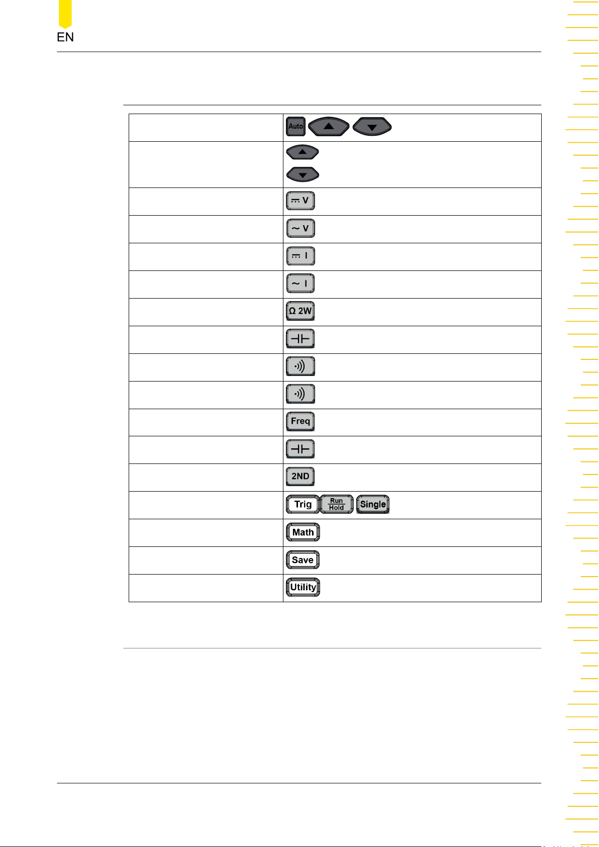
Front Panel Operation
5
Front Panel Operation
•
To Set the Range
•
To Set the Measurement
Rate
•
To Measure DC Voltage
•
To Measure AC Voltage
•
To Measure DC Current
•
To Measure AC Current
•
To Measure Resistance
•
To Measure Capacitance
•
To Test Continuity
•
To Check Diode
•
To Measure Frequency/
Period
•
Any Sensor
Measurement
•
Preset Mode
•
Trigger
•
Math Operation
•
To Store and Load
•
System Utility Function
Setting
5.1 To Set the Range
For the specified measurement item, the range can be set to Auto or specified values.
You can set the range to Auto, and then the proper range for the current
measurement will be automatically selected. It is convenient for you to make
measurements. You can also select a specified range manually to obtain higher
reading precision.
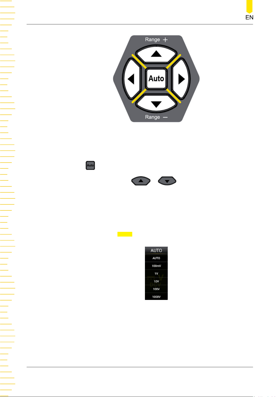
The range selection keys are located at the right part of the front panel, as shown in
the figure below.
Copyright ©RIGOL TECHNOLOGIES CO., LTD. All rights reserved. DM858 Series User Guide
31
Page 44
Front Panel Operation
Figure 5.1 Range and Rate Selection Keys
Operation Method:
Auto: Press to set the range to Auto.
Specified range selection: Press or to select the available range.
You can also set the range for each measurement item in the specified measurement
interface.
For each measurement item displayed on the screen, click or tap the Measure label at
the bottom of the screen to enter the specified measurement item interface. Click or
tap the drop-down list of
Range to select AUTO or the specified range value.
Remarks:
• When the input signal exceeds the current range (except the Frequency
DM858 Series User Guide
32
Figure 5.2 Range Selection Menu
measurement), a message "OVERLOAD" is displayed on the screen.
Copyright ©RIGOL TECHNOLOGIES CO., LTD. All rights reserved.
Page 45

• The range of the Frequency is from 20 Hz to 100 kHz. Once exceeding the range,
the instrument does not display the Overload prompt message, but the accuracy
of the measurement results cannot be guaranteed.
• The range is automatically set to AUTO after a reset.
• Auto range is recommended if you are not sure about the measurement range
so as to protect the instrument and obtain accurate data.
• The ranges for continuity test and diode measurement are fixed. The fixed range
for Continuity test is 1 kΩ; and the fixed range of DIODE measurement is 2.1 V.
5.2 To Set the Measurement Rate
Front Panel Operation
The multimeter provides three measurement rates: Fast, Medium, and Slow.
The measurement rate can be adjusted by using the Left and Right arrow keys on the
front panel. Press to increase the rate and press to decrease the rate.
Remarks:
1. Three measurement rates are available to choose for the DCV, DCI, ACV, ACI, 2WR,
and 4WR measurements.
2. The reading resolution is correlated to the measurement rate.
- Slow corresponds to 5.5 reading resolution;
- Medium and Fast correspond to 4.5 reading resolution;
- Sensor has a fixed 5.5 reading resolution which corresponds to Slow;
- Continuity and Diode have a fixed 4.5 reading resolution which corresponds to
Fast;
- Frequency/Period has a fixed 5.5 reading resolution which corresponds to Slow;
- Capacitance has a fixed 3.5 reading resolution which corresponds to Slow.
5.3 Basic Measurement Functions
The basic measurement functions of the instrument include:
•
To Measure DC Voltage
Copyright ©RIGOL TECHNOLOGIES CO., LTD. All rights reserved. DM858 Series User Guide
33
Page 46
Front Panel Operation
•
To Measure AC Voltage
•
To Measure DC Current
•
To Measure AC Current
•
To Measure Resistance
•
To Measure Capacitance
•
To Test Continuity
•
To Check Diode
•
To Measure Frequency/Period
•
Any Sensor Measurement
5.3.1 To Measure DC Voltage
The instrument can measure up to 1,000 V DC voltage. The following section
introduces the connection methods and measurement methods of DC voltage.
NOTE
DCV measurement is selected by default.
Operation Procedures:
1. To enter the DC voltage measurement interface, perform either one of the
following two operations.
- Press on the front panel;
- Click or tap the main measurement item shown at the left part of the main
display area. The measurement items are displayed. Click or tap to select
DM858 Series User Guide
34
to enter the DC voltage interface.
Copyright ©RIGOL TECHNOLOGIES CO., LTD. All rights reserved.
Page 47
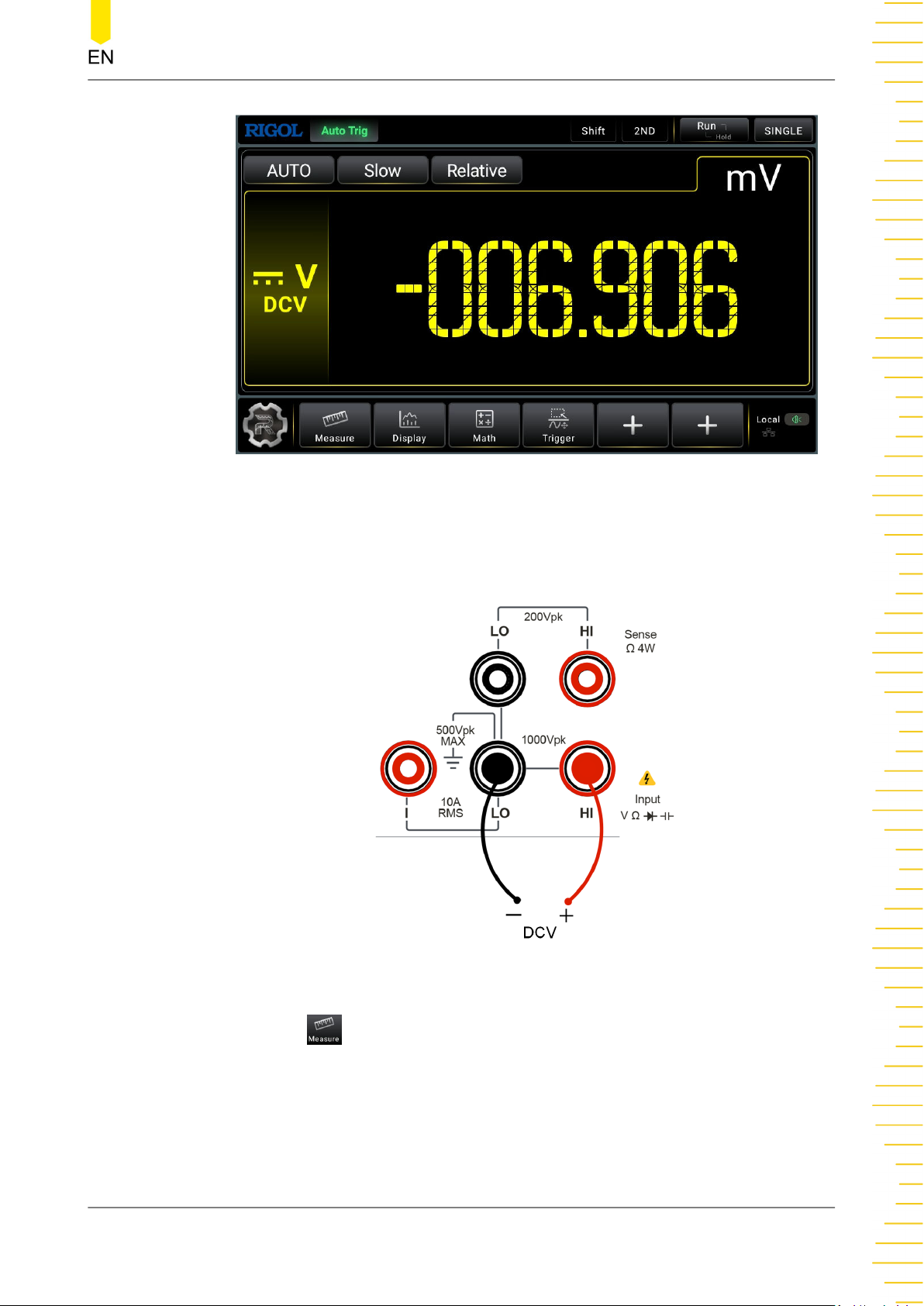
Front Panel Operation
Figure 5.3 DC Voltage Measurement Interface
2. Connect red lead to terminal Input-HI and black lead to terminal Input-LO, as
shown in the figure below.
Figure 5.4 DC Voltage Measurement Connection Diagram
3. Click or tap to set the measurement parameters of DC voltage: Range,
Impedance (available to set when the Range is not set to Auto), and Rate.
Copyright ©RIGOL TECHNOLOGIES CO., LTD. All rights reserved. DM858 Series User Guide
35
Page 48
Front Panel Operation
Table 5.2 DC Voltage Measurement Parameter Setting
Parameter Description
Range* Auto, 100 mV, 1 V, 10V, 100 V, 1000V
Available to set when the Range is a specified value rather than
Auto.
10 GΩ, 11.2 MΩ
Impedance
- When you select "11.2 MΩ", the input impedance for all the
ranges is 11.2 MΩ.
- When you select "10 GΩ", the input impedance for 100 mV
and 1 V ranges is "10 GΩ", but the input impedance for the
10V, 100 V, 1000V ranges is "11.2 MΩ".
Rate Fast, Medium, Slow
NOTE
- 20% over range on all ranges except 1000 V range.
- The range can be set to Auto or a specified value (available range options for Range
menu).
- A 1000 V input protection is available in all ranges and a 20% overrange is available on
all ranges except 1000 V.
- If the reading exceeds 1000 V in 1000 V range, "OVER LOAD" will be displayed.
4. Click or tap to enable or disable the relative operation function. When
enabled, the displayed reading value is the result obtained by subtracting the set
relative value from the actual measurement value. For the relative value setting
methods, refer to descriptions in "
Math Operation
".
5. Read the measured value
When reading the measurement results, you can use the arrow keys to switch the
reading rate.
6. Hold the reading data
Press
to run and hold the reading data displayed on the screen.
5.3.2 To Measure DC Current
The instrument can measure up to 10 A(DM858)/3 A(DM858E) DC current. The
following section introduces the connection methods and measurement methods of
DC Current.
DM858 Series User Guide
36
Copyright ©RIGOL TECHNOLOGIES CO., LTD. All rights reserved.
Page 49
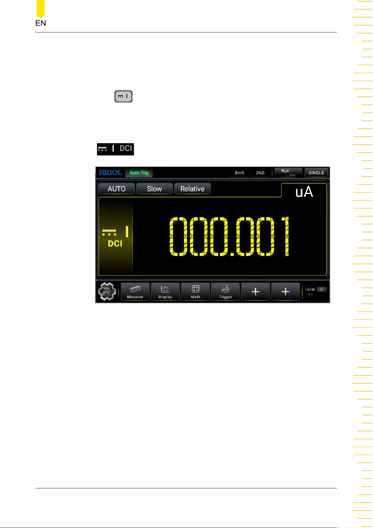
Front Panel Operation
Operation Procedures:
1. To enter the DC current measurement interface, perform either one of the
following two operations.
- Press on the front panel;
- Click or tap the main measurement item shown at the left part of the main
display area. The measurement items are displayed. Click or tap to select
to enter the DC current interface.
Figure 5.5 DC Current Measurement Interface
2. Connect red lead to terminal Input-I and black lead to terminal Input-LO, as shown
in the figure below.
Copyright ©RIGOL TECHNOLOGIES CO., LTD. All rights reserved. DM858 Series User Guide
37
Page 50
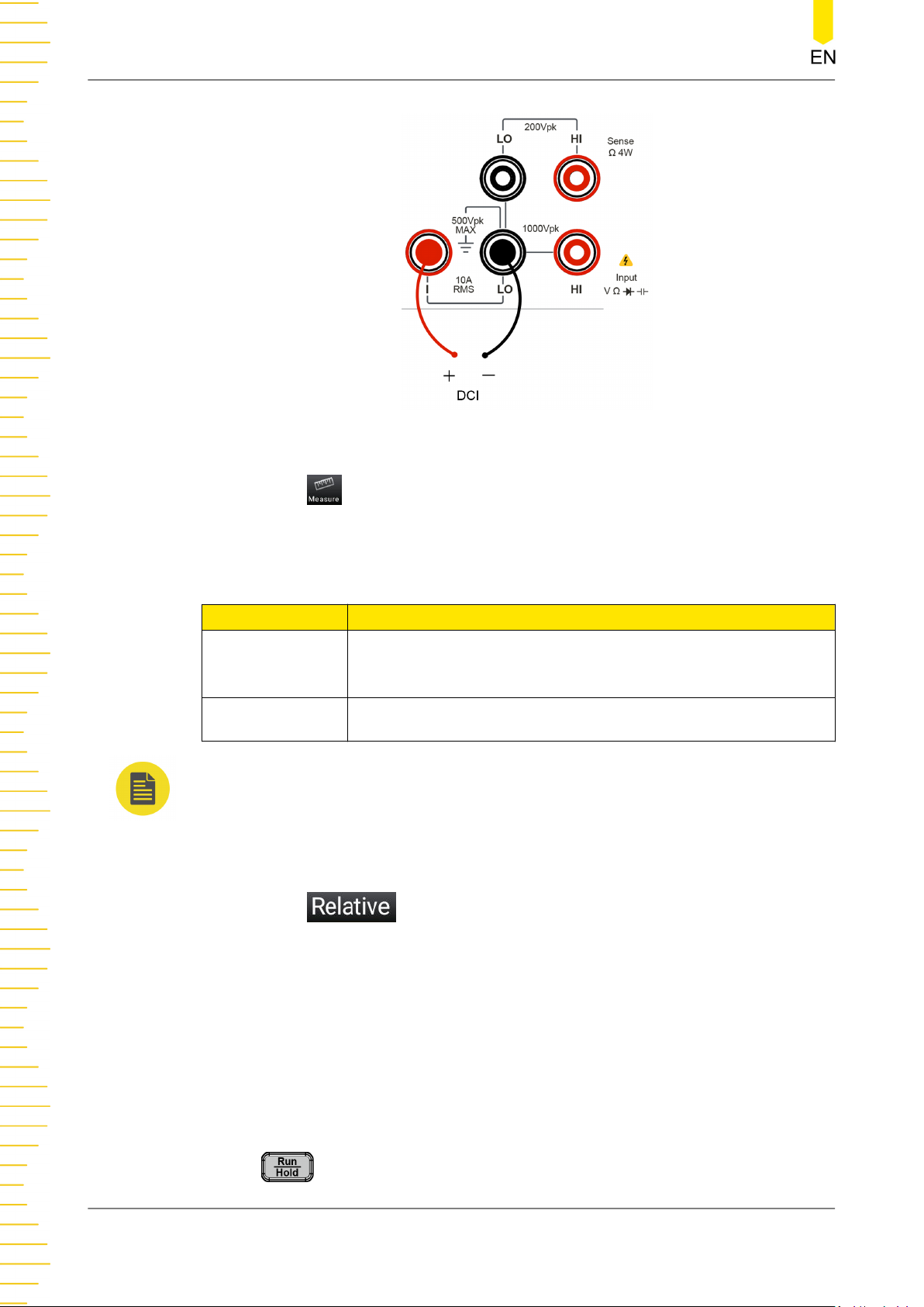
Front Panel Operation
Figure 5.6 DC Current Measurement Connection Diagram
3. Click or tap to set the measurement parameters of DC current: Range and
Rate.
Table 5.3 DC Current Measurement Parameter Setting
Parameter Remarks
Range*
Auto, 100 μA, 1 mA, 10 mA, 100 mA, 1 A, 10 A (DM858)/3 A
(DM858E)
Rate Fast, Medium, Slow
NOTE
20% over range on all ranges except 10 A range. The range can be set to Auto or the given
specified values.
4. Click or tap to enable or disable the relative operation function. When
enabled, the displayed reading value is the result obtained by subtracting the set
relative value from the actual measurement value. For the relative value setting
methods, refer to descriptions in "
Math Operation
".
5. Read the measured value
When reading the measurement results, you can use the arrow keys to switch the
reading rate.
6. Hold the reading data
Press
DM858 Series User Guide
38
to run and hold the reading data displayed on the screen.
Copyright ©RIGOL TECHNOLOGIES CO., LTD. All rights reserved.
Page 51
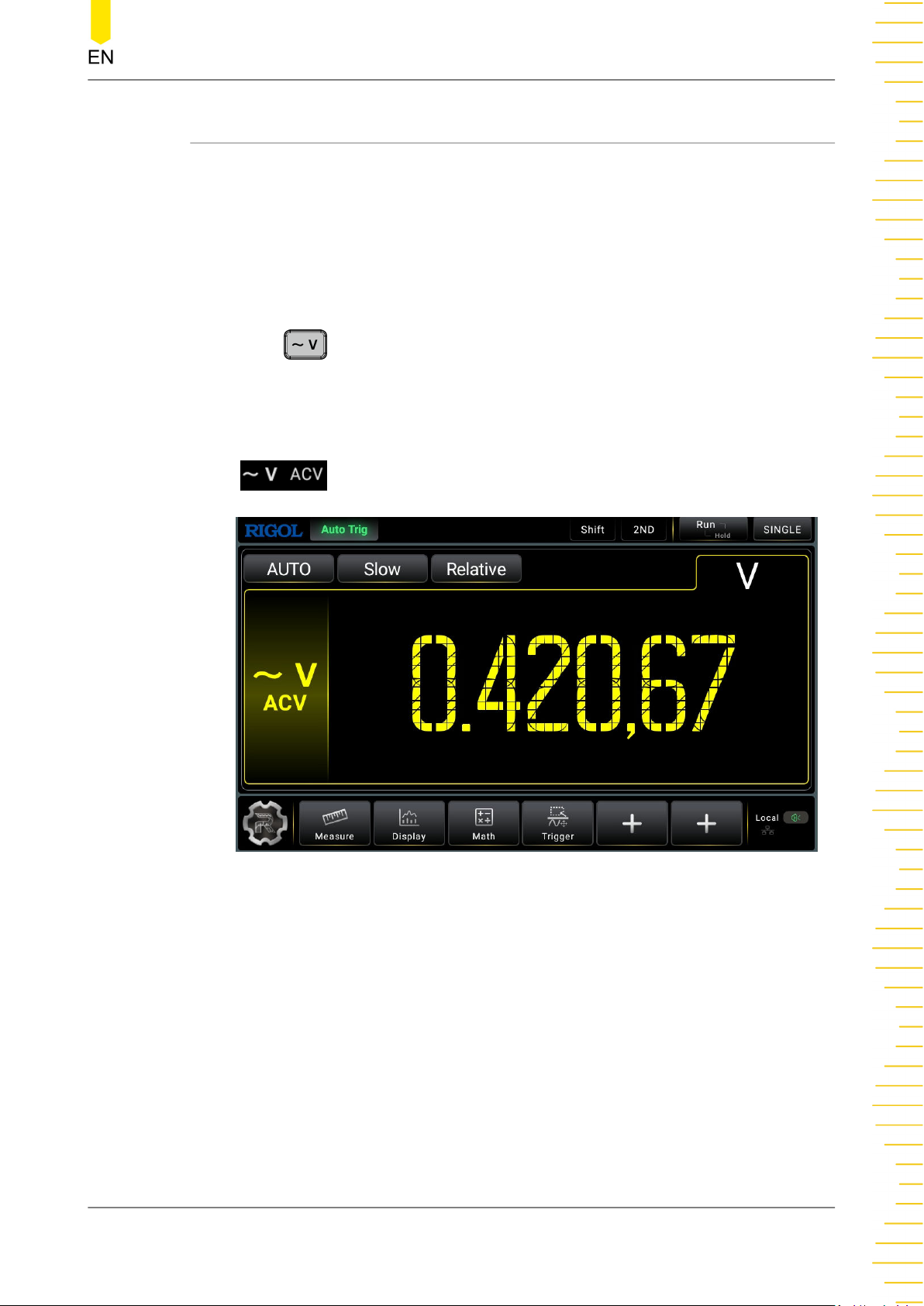
5.3.3 To Measure AC Voltage
The instrument can measure up to 750 V AC voltage. The following section introduces
the connection methods and measurement methods of AC voltage.
Operation Procedures:
1. To enter the AC voltage measurement interface, perform either one of the
following two operations.
- Press on the front panel;
- Click or tap the main measurement item shown at the left part of the main
display area. The measurement items are displayed. Click or tap to select
Front Panel Operation
to enter the AC voltage interface.
Figure 5.7 AC Voltage Measurement Interface
2. Connect red lead to terminal Input-HI and black lead to terminal Input-LO, as
shown in the figure below.
Copyright ©RIGOL TECHNOLOGIES CO., LTD. All rights reserved. DM858 Series User Guide
39
Page 52
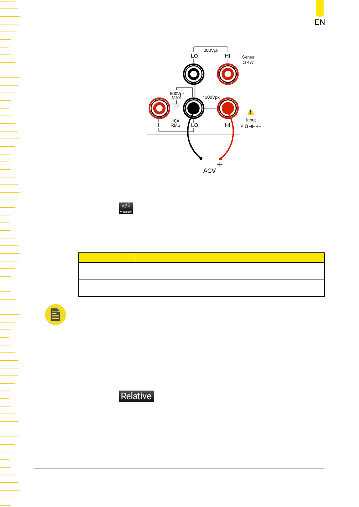
Front Panel Operation
Figure 5.8 AC Voltage Measurement Connection Diagram
3. Click or tap to set the measurement parameters of AC voltage: Range and
Rate
Table 5.4 AC Voltage Measurement Parameter Setting
Parameter Description
Range* Auto, 100 mV, 1 V, 10 V, 100 V, 750 V
Rate Fast, Medium, Slow
NOTE
- 20% over range on all ranges except 750 V range.
- The range can be set to Auto or a specified value (available range options for Range
menu).
- A 750 V input protection is available in all ranges and a 20% overrange is available on all
ranges except 750 V.
- If the reading exceeds 750 V in 750 V range, "OVER LOAD" will be displayed.
4. Click or tap to enable or disable the relative operation function. When
enabled, the displayed reading value is the result obtained by subtracting the set
relative value from the actual measurement value. For the relative value setting
methods, refer to descriptions in "
5. Read the measured value
DM858 Series User Guide
40
Math Operation
Copyright ©RIGOL TECHNOLOGIES CO., LTD. All rights reserved.
".
Page 53
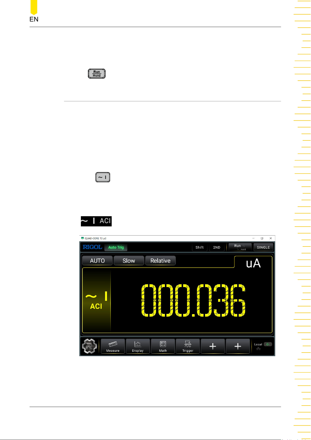
When reading the measurement results, you can use the arrow keys to switch the
reading rate.
6. Hold the reading data
Press to run and hold the reading data displayed on the screen.
5.3.4 To Measure AC Current
The instrument can measure up to 10 A(DM858)/3 A(DM858E) AC current . The
following section introduces the connection methods and measurement methods of
AC current.
Operation Procedures:
1. To enter the AC current measurement interface, perform either one of the
following two operations.
Front Panel Operation
- Press on the front panel;
- Click or tap the main measurement item shown at the left part of the main
display area. The measurement items are displayed. Click or tap to select
to enter the AC current measurement interface.
Figure 5.9 AC Current Measurement Interface
2. Connect red lead to terminal Input-I and black lead to terminal Input-LO, as shown
in the figure below.
Copyright ©RIGOL TECHNOLOGIES CO., LTD. All rights reserved. DM858 Series User Guide
41
Page 54
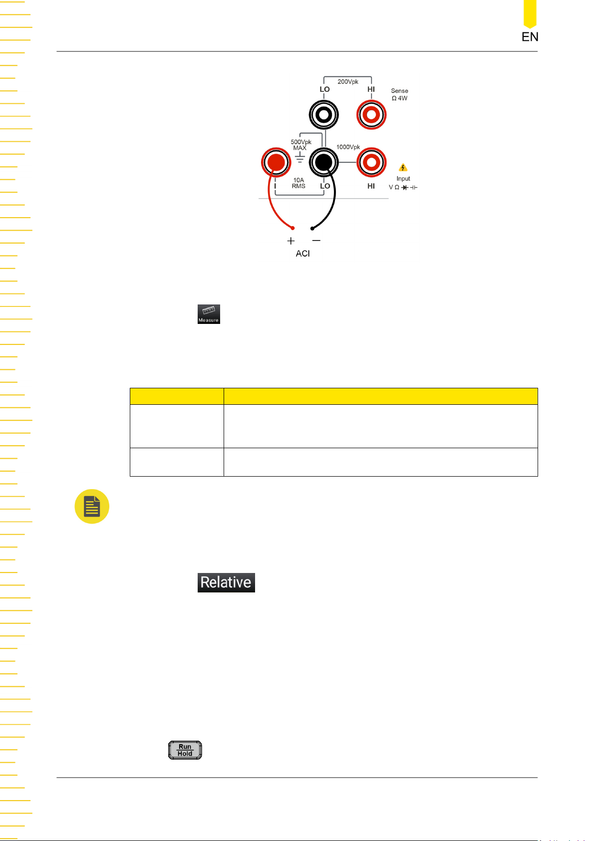
Front Panel Operation
Figure 5.10 AC Current Measurement Connection Diagram
3. Click or tap to set the measurement parameters of AC current: Range and
Rate
Table 5.5 AC Current Measurement Parameter Setting
Parameter Remarks
Range*
Auto, 100 μA, 1 mA, 10 mA, 100 mA, 1 A, 10 A(DM858)/3
A(DM858E)
Rate Fast, Medium, Slow
NOTE
20% over range on all ranges except 10 A range. The range can be set to Auto or the given
specified values.
4. Click or tap to enable or disable the relative operation function. When
enabled, the displayed reading value is the result obtained by subtracting the set
relative value from the actual measurement value. For the relative value setting
methods, refer to descriptions in "
Math Operation
".
5. Read the measured value
When reading the measurement results, you can use the arrow keys to switch the
reading rate.
6. Hold the reading data
Press
DM858 Series User Guide
42
to run and hold the reading data displayed on the screen.
Copyright ©RIGOL TECHNOLOGIES CO., LTD. All rights reserved.
Page 55
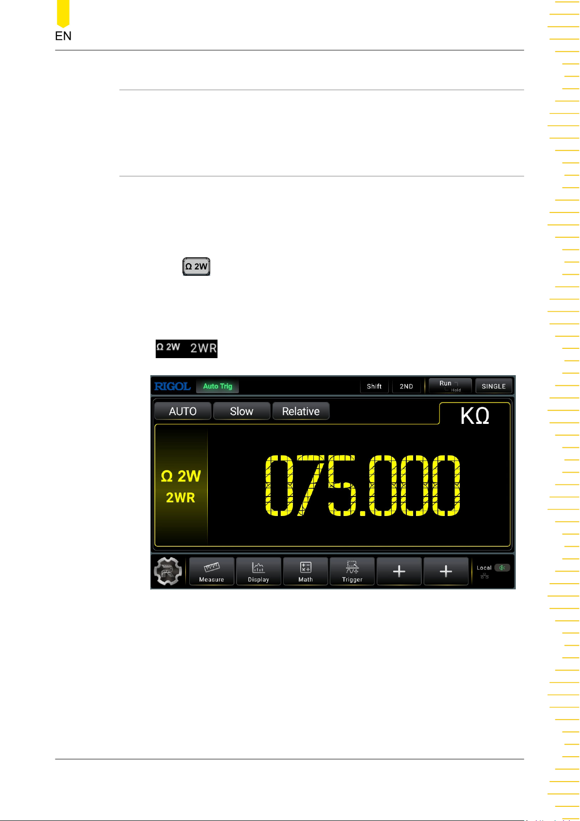
5.3.5 To Measure Resistance
The instrument provides 2-wire (2WR) and 4-wire (4WR) resistance measurements.
The following section introduces the connection methods and measurement methods
of 2WR and 4WR resistance measurements.
5.3.5.1 2WR Measurement
Operation Procedures:
1. To enter the 2WR measurement interface, perform either one of the following two
operations.
- Press on the front panel;
- Click or tap the main measurement item shown at the left part of the main
Front Panel Operation
display area. The measurement items are displayed. Click or tap to select
to enter the 2WR measurement interface.
Figure 5.11 2WR Measurement Interface
2. Connect red lead to terminal Input-HI and black lead to terminal Input-LO, as
shown in the figure below.
Copyright ©RIGOL TECHNOLOGIES CO., LTD. All rights reserved. DM858 Series User Guide
43
Page 56
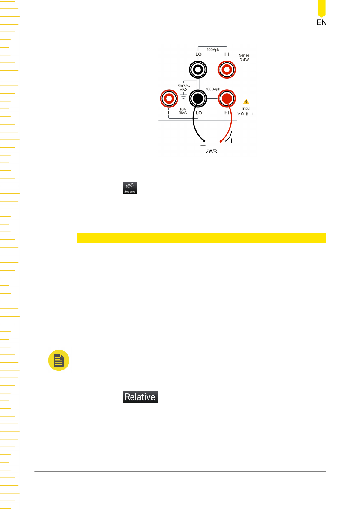
Front Panel Operation
Figure 5.12 2WR Measurement Connection Diagram
3. Click or tap to set the measurement range, rate, and display digit (available
when the range is set to 1 MΩ or above and when the measurement rate is Slow).
Table 5.6 2WR Measurement Parameter Setting
Parameter Description
Range* Auto, 100 Ω, 1 kΩ, 10 kΩ, 100 kΩ, 1 MΩ, 10 MΩ, and 50 MΩ
Rate Slow, Medium, Fast
1/2
Digit (available
1/2
4
, 5
when the range is
set to 1 MΩ or
above and when
the measurement
rate is Slow)
4. Click or tap to enable or disable the relative operation function.
When enabled, the displayed reading value is the result obtained by subtracting
the set relative value from the actual measurement value. For the relative value
setting methods, refer to descriptions in "
DM858 Series User Guide
44
NOTE
20% overrange in all ranges. You can select Auto or a specified range value.
Math Operation
Copyright ©RIGOL TECHNOLOGIES CO., LTD. All rights reserved.
".
Page 57
TIP
If the measured resistance is small, Relative operation is recommended to reduce the error
caused by test lead. If no oRelative operation is used, an additional error of 0.2 Ω is added.
To test the resistance above 1 MΩ, avoid external interference.
5. Read the measured value
When reading the measurement results, you can use the arrow keys to switch the
reading rate.
6. Hold the reading data
Press to run and hold the reading data displayed on the screen.
5.3.5.2 4WR Measurement
Front Panel Operation
When the measured resistance is lower than 100 kΩ, the 4-wire resistance
measurement is recommended to reduce the measurement error caused by test lead
resistance and contact resistance between the probe and the testing point because
these two resistances cannot be ignored comparing with the measured resistance.
Operation Procedures:
1. To enter the 4WR measurement interface, perform either one of the following two
operations.
- Press > to enter the 4WR measurement interface.
- Click or tap the main measurement item shown at the left part of the main
display area. The measurement items are displayed. Click or tap to select
to enter the 4WR measurement interface.
Copyright ©RIGOL TECHNOLOGIES CO., LTD. All rights reserved. DM858 Series User Guide
45
Page 58
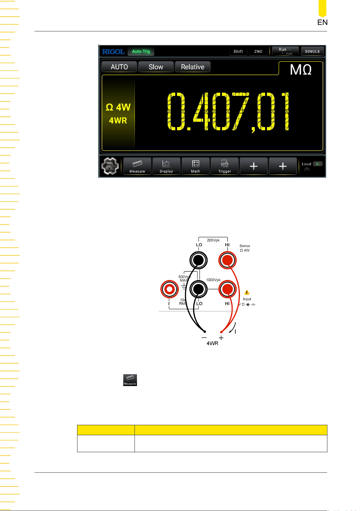
Front Panel Operation
-
Figure 5.13 4WR Measurement Interface
2. Connect red leads to terminal Input-HI and HI-Sense, black leads to terminal
Input-LO and Low Sense, as shown in the figure below.
Figure 5.14 4WR Measurement Connection Diagram
3. Click or tap to set the measurement range, rate, and display digit (available
when the range is set to 1 MΩ or above).
Table 5.7 4WR Measurement Parameter
Parameter Description
Range* Auto, 100 Ω, 1 kΩ, 10 kΩ, 100 kΩ, 1 MΩ, 10 MΩ, and 50 MΩ
DM858 Series User Guide
46
Copyright ©RIGOL TECHNOLOGIES CO., LTD. All rights reserved.
Page 59
Front Panel Operation
Parameter Description
Rate Slow, Medium, Fast
1/2
Digit (available
1/2
4
, 5
when the range is
set to 1 MΩ or
above)
NOTE
20% overrange in all ranges. You can select Auto or a specified range value.
4. Click or tap to enable or disable the relative operation function.
When enabled, the displayed reading value is the result obtained by subtracting
the set relative value from the actual measurement value. For the relative value
setting methods, refer to descriptions in "
Math Operation
".
5. Read the measured value
When reading the measurement results, you can use the arrow keys to switch the
reading rate.
6.
Hold the reading data
Press to run and hold the reading data displayed on the screen.
NOTE
Please do not put the terminals of the resistance on the conductive plane or in your hand
to avoid error. The larger the resistance, the more the impact on the measurement results.
5.3.6 To Measure Capacitance
The instrument can measure up to 1 mF/10 mF (only available for DM858)
capacitance. The following section introduces the connection methods and
measurement methods of capacitance.
Operation Procedures:
1. To enter the capacitance measurement interface, perform either one of the
following two operations.
- Press on the front panel;
Copyright ©RIGOL TECHNOLOGIES CO., LTD. All rights reserved. DM858 Series User Guide
47
Page 60
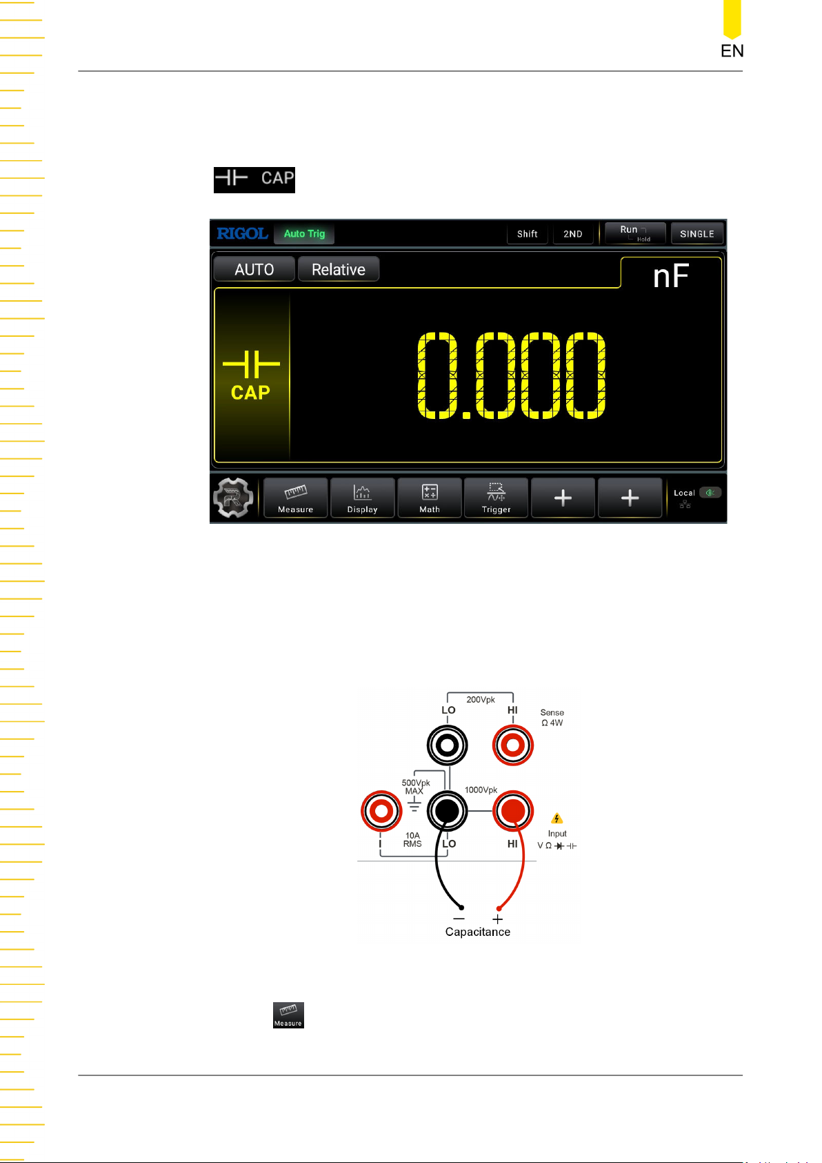
Front Panel Operation
- Click or tap the main measurement item shown at the left part of the main
display area. The measurement items are displayed. Click or tap to select
to enter the capacitance measurement interface.
Figure 5.15 Capacitance Measurement Setting Interface
2. Connect red lead to terminal Input-HI and anode of the capacitance. Connect the
black lead to both terminal Input-LO and cathode of the capacitance, as shown in
the figure below.
3. Click or tap to set the range of the capacitance measurement.
DM858 Series User Guide
48
Figure 5.16 Capacitance Measurement Connection Diagram
Copyright ©RIGOL TECHNOLOGIES CO., LTD. All rights reserved.
Page 61
Table 5.8 Capacitance Measurement Parameter Settings
Parameter Description
Front Panel Operation
Range*
Auto, 1 nF, 10 nF, 100 nF, 1 μF, 10 μF, 100 μF, 1 mF, and 10 mF
(only available for DM858)
NOTE
20% overrange on all ranges.
4. Click or tap to enable or disable the relative operation function. When
enabled, the displayed reading value is the result obtained by subtracting the set
relative value from the actual measurement value. For the relative value setting
methods, refer to descriptions in "
Math Operation
".
5. Read the measured value
The capacitance measurement is measured at a fixed "slow" rate with a 3.5-digit
display. Therefore, the reading rate cannot be adjusted during measurement
results reading.
6.
Hold the reading data
Press
to run and hold the reading data displayed on the screen.
TIP
Before measuring the electrolytic capacitor, you should first short-circuit the two pins of the
electrolytic capacitor to discharge it.
5.3.7 To Test Continuity
The continuity test checks that the resistance in the DUT is low enough to be
considered continuous. In this case, the beeper sounds, if enabled, to inform you of
the continuity situation.
Operation Procedures:
1. To enter the continuity measurement interface, perform either one of the following
two operations.
- Press on the front panel;
Copyright ©RIGOL TECHNOLOGIES CO., LTD. All rights reserved. DM858 Series User Guide
49
Page 62
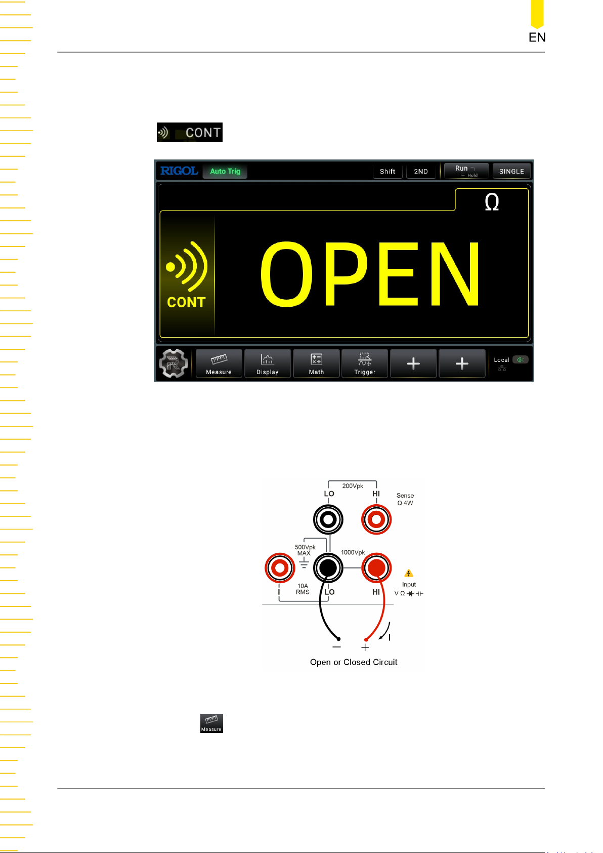
Front Panel Operation
- Click or tap the main measurement item shown at the left part of the main
display area. The measurement items are displayed. Click or tap to select
to enter the continuity measurement interface.
Figure 5.17 Continuity Test Interface
2. Connect red lead to terminal Input-HI and black lead to terminal Input-LO, as
shown in the figure below.
Figure 5.18 Continuity Test Connection Diagram
3. Click or tap
resistance is 10 Ω. The value is set before leaving factory and you can directly
DM858 Series User Guide
50
to set the short-circuit resistance. By default, the short-circuit
Copyright ©RIGOL TECHNOLOGIES CO., LTD. All rights reserved.
Page 63
Front Panel Operation
perform the continuity test. If you do not need to modify the parameter, go to the
next step.
Table 5.9 Continuity Test Parameter Settings
Parameter Description
Short Circuit Resistance 10 Ω (default); from 1 Ω to 1,000 Ω
Enables or disables the beeper. If the
Beeper
beeper is enabled, beeper sounds when
the circuit is considered to be
continuous.
NOTE
The short-circuit resistance value is stored in the non-volatile memory and will remain
unchanged at power-off.
4. Measurement Display Results
For the open circuit or measured value exceeds 1.2 kΩ, OPEN is displayed on the
screen; When the measured value is smaller than the set short-circuit resistance,
the actual resistance value is displayed on the screen. At this time, if the beeper is
enabled, the beeper sounds. When the measured value is greater than the set
short-circuit resistance and less than 1.2 kΩ, the beeper does not sound whether it
is enabled or not, and the actual resistance value is displayed on the screen.
5.3.8 To Check Diode
Operation Procedures:
1. To enter the diode measurement interface, perform either one of the following two
operations.
- Press > on the front panel to enter the diode measurement
Interface.
- Click or tap the main measurement item shown at the left part of the main
display area. The measurement items are displayed. Click or tap to select
to enter the diode measurement interface.
Copyright ©RIGOL TECHNOLOGIES CO., LTD. All rights reserved. DM858 Series User Guide
51
Page 64
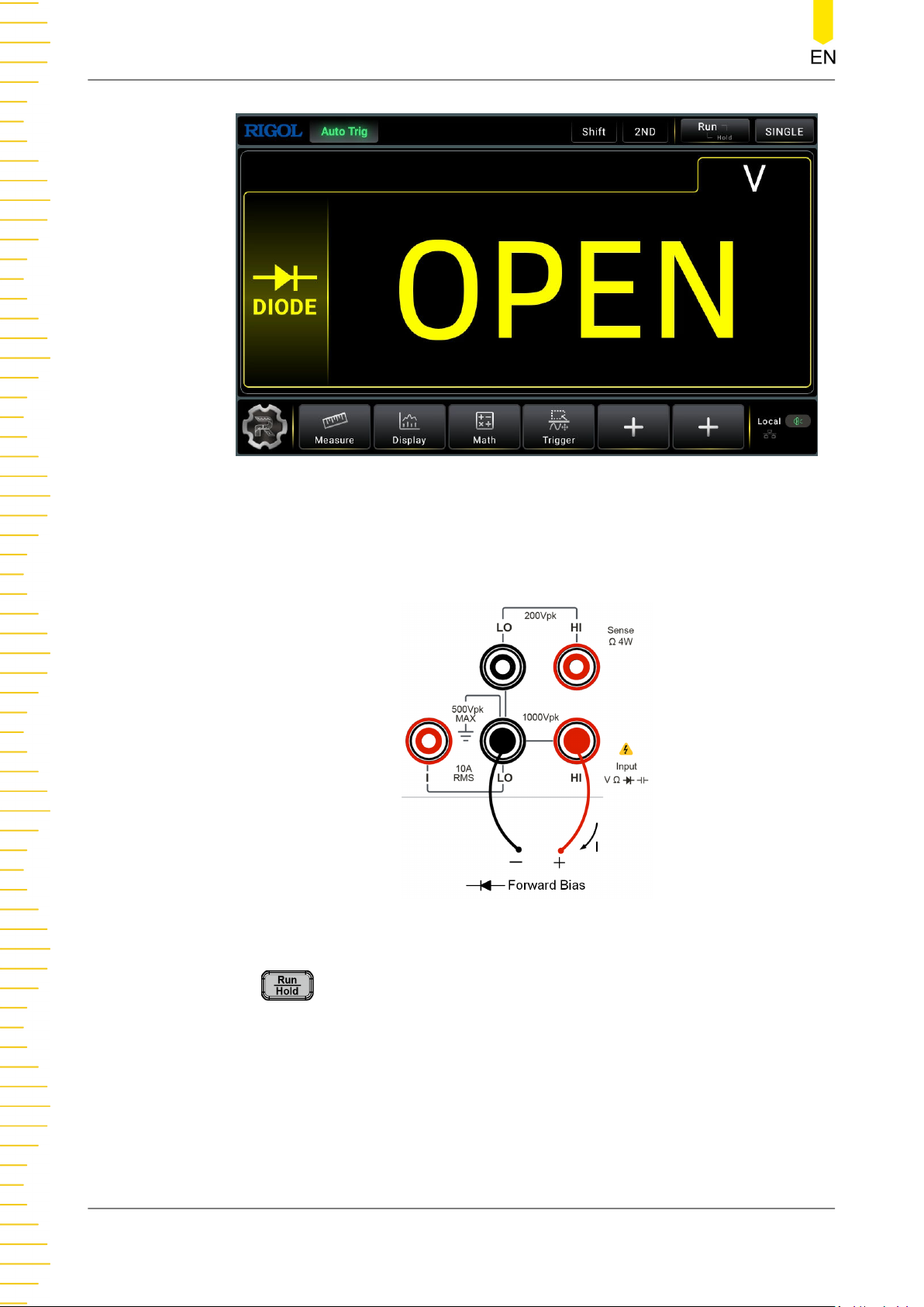
Front Panel Operation
Figure 5.19 Diode Measurement Interface
2. Connect red lead to both terminal Input-HI and anode of the Diode and black lead
to both terminal Input-LO and cathode of the Diode, as shown in the figure below.
Figure 5.20 Diode Measurement Connection Diagram
3. Press on the front panel, and the secondary display area is displayed. Click
or tap the ON/OFF tab for Beeper to enable or disable the beeper. When the diode
is properly connected, the instrument beeps for one time (If beeper is enabled).
4. Different conditions for Measurement Result:
DM858 Series User Guide
52
Copyright ©RIGOL TECHNOLOGIES CO., LTD. All rights reserved.
Page 65
- OPEN: when OPEN is displayed on the screen, it indicates that the diode is
open-circuit or the measured forward voltage drop is less than 0.1 V or greater
than 2.1 V.
- Measured Value: when the measured forward voltage drop is within the range
of 0.1 V and 2.1 V.
- Measured Value and with Beeper On: when the measured values are displayed
on the screen, with beeper on, the measured forward voltage drop is within the
range of 0.1 V and 2.1 V.
5.3.9 To Measure Frequency/Period
Front Panel Operation
The frequency/period of a signal could be measured with the frequency/period
measurement function. The following section introduces how to perform Frequency
and Period measurement with the instrument.
5.3.9.1 Measure Frequency
Operation Procedures:
1. To enter the frequency measurement interface, perform either one of the
following two operations.
- Press on the front panel;
- Click or tap the main measurement item shown at the left part of the main
display area. The measurement items are displayed. Click or tap to select
to enter the frequency measurement interface.
Copyright ©RIGOL TECHNOLOGIES CO., LTD. All rights reserved. DM858 Series User Guide
53
Page 66
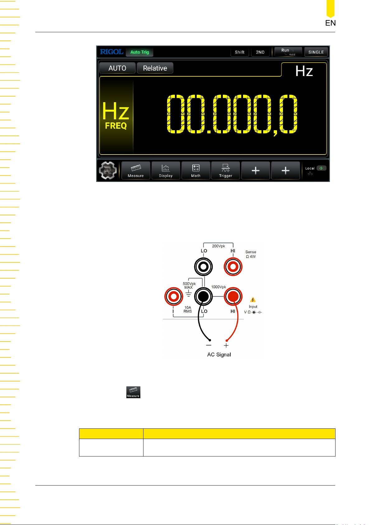
Front Panel Operation
Figure 5.21 Frequency Measurement Interface
2. Connect red lead to terminal Input-HI and black lead to terminal Input-LO, as
shown in the figure below.
Figure 5.22 Frequency Measurement Connection Diagram
3. Click or tap to set the range of the frequency measurement.
Table 5.10 Frequency Measurement Settings
Parameter Description
Range Auto, 100 mV, 1 V, 10V, 100 V, 750 V
DM858 Series User Guide
54
Copyright ©RIGOL TECHNOLOGIES CO., LTD. All rights reserved.
Page 67
Front Panel Operation
4. Click or tap to enable or disable the relative operation function.
When enabled, the displayed reading value is the result obtained by subtracting
the set relative value from the actual measurement value. For the relative value
setting methods, refer to descriptions in "
Math Operation
".
5. Read the measured value
The frequency measurement is measured at a fixed "slow" rate with a 5.5-digit
display. Therefore, the reading rate cannot be adjusted during measurement
results reading.
6. Hold the reading data
Press
5.3.9.2 Measure Period
Operation Procedures:
1. To enter the period measurement interface, perform either one of the following
two operations.
- Press > on the front panel;
- Click or tap the main measurement item shown at the left part of the main
display area. The measurement items are displayed. Click or tap to select
to run and hold the reading data displayed on the screen.
to enter the period measurement interface.
Copyright ©RIGOL TECHNOLOGIES CO., LTD. All rights reserved. DM858 Series User Guide
55
Page 68
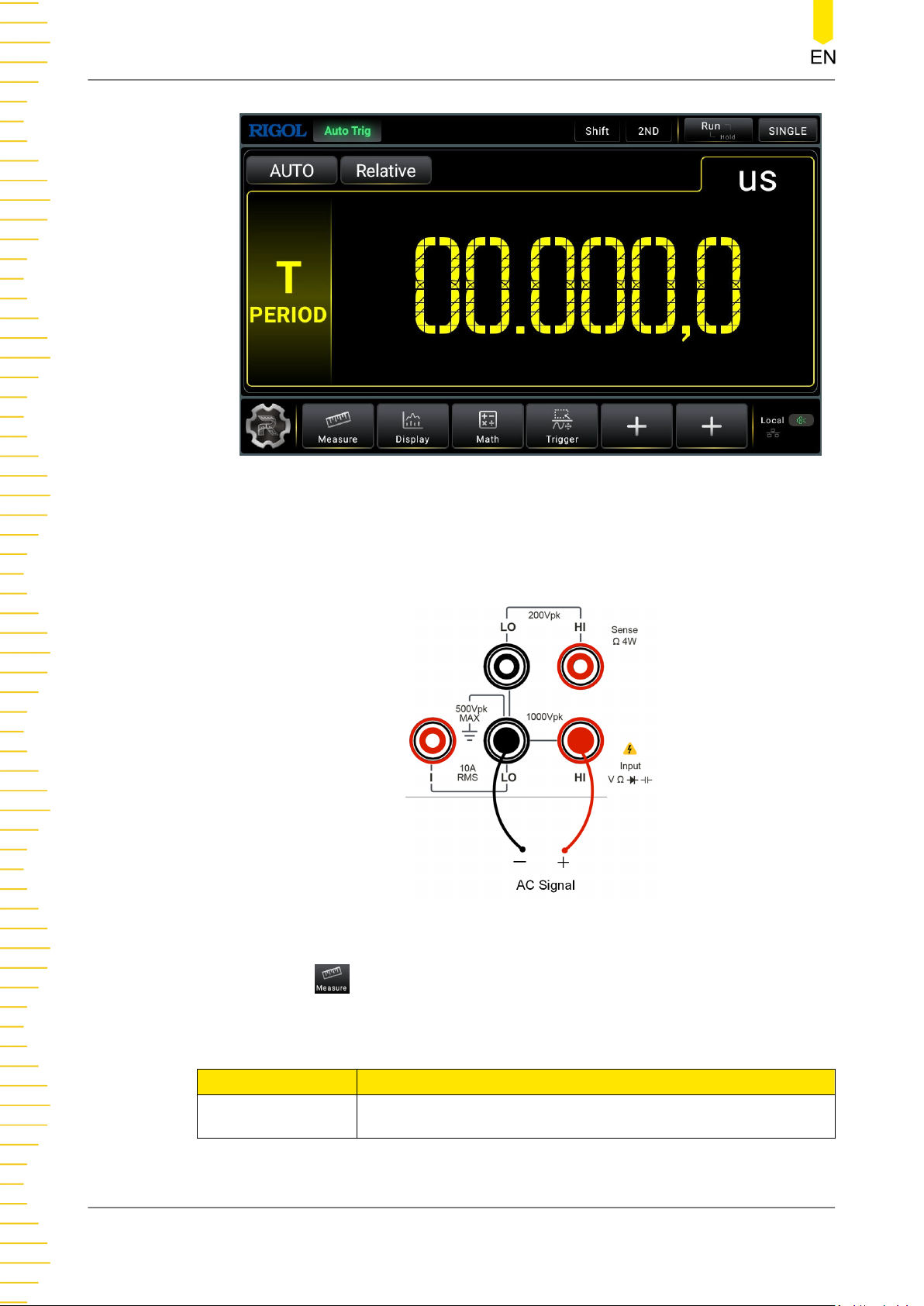
Front Panel Operation
Figure 5.23 Period Measurement Interface
2. Connect red lead to terminal Input HI and black lead to terminal Input LO, as
shown in the figure below.
Figure 5.24 Period Measurement Connection Diagram
3. Click or tap to set the range of the period measurement.
Table 5.11 Period Measurement Parameter Setting
Parameter Description
Range Auto, 100 mV, 1 V, 10V, 100 V, 750V
DM858 Series User Guide
56
Copyright ©RIGOL TECHNOLOGIES CO., LTD. All rights reserved.
Page 69
Front Panel Operation
4. Click or tap to enable or disable the relative operation function.
When enabled, the displayed reading value is the result obtained by subtracting
the set relative value from the actual measurement value. For the relative value
setting methods, refer to descriptions in "
5. Read the measured value
The period measurement is measured at a fixed "slow" rate with a 5.5-digit
display. Therefore, the reading rate cannot be adjusted during measurement
results reading.
6. Hold the reading data
Math Operation
".
Press
to run and hold the reading data displayed on the screen.
5.3.10 Any Sensor Measurement
By using any sensor measurement, you can connect Pressure Sensor, Flux Sensor or
Temperature Sensor easily. This function enables you to easily convert a measured
physical quantity (such as pressure, flow rate and temperature) into a quantity that
can be easily measured (such as voltage, current or resistance). By pre-inputting a
response curve, the multimeter converts and amends the data according to the
internal arithmetic and displays the physical quantity measured on the screen. Users
can edit and modify the display unit of the measured physical quantity at will.
The multimeter supports DCV, DCI, Freq, 2WR, 4WR, and temperature sensor
measurement (TC, RTD, Therm). Meanwhile, there are 10 groups of basic Sensor
preset within the instrument.
Connection
Different sensors have different connection methods. For the Voltage Sensor,
Resistance Sensor, Thermocouple Sensor and Frequency Sensor, please connect the
red lead to terminal Input-HI and black lead to terminal Input-LO, as shown in the
figure below.
Copyright ©RIGOL TECHNOLOGIES CO., LTD. All rights reserved. DM858 Series User Guide
57
Page 70
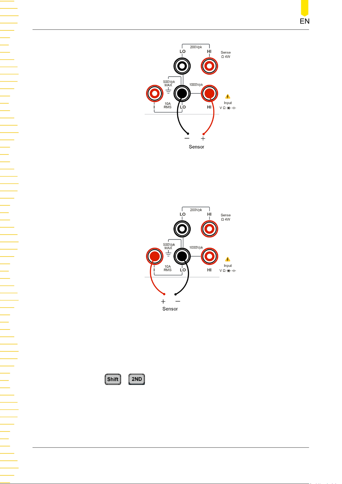
Front Panel Operation
Figure 5.25 Voltage, Resistance, TC, Frequency Sensor Connection Method
For the Current Sensor, please connect the red lead to terminal Input-HI and black
lead to terminal Input-LO, as shown in the figure below.
Figure 5.26 Current Sensor Connection Method
1. To enter the sensor measurement interface, perform either one of the following
two operations.
- Press > on the front panel to enter the sensor measurement
DM858 Series User Guide
58
interface.
Copyright ©RIGOL TECHNOLOGIES CO., LTD. All rights reserved.
Page 71
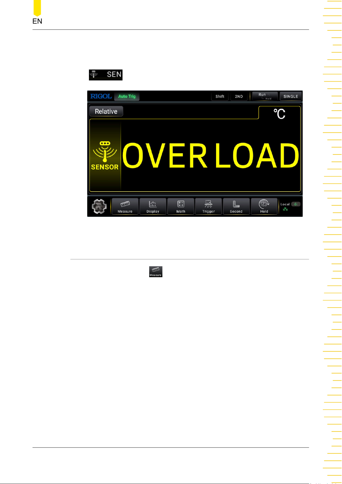
Front Panel Operation
- Click or tap the main measurement item shown at the left part of the main
display area. The measurement items are displayed. Click or tap to select
to enter the sensor measurement interface.
Figure 5.27 Sensor Measurement Interface
5.3.10.1 To Measure the Temperature Sensor
In
Figure 5.27
, click or tap to enter the any sensor measurement setting
interface.
Copyright ©RIGOL TECHNOLOGIES CO., LTD. All rights reserved. DM858 Series User Guide
59
Page 72
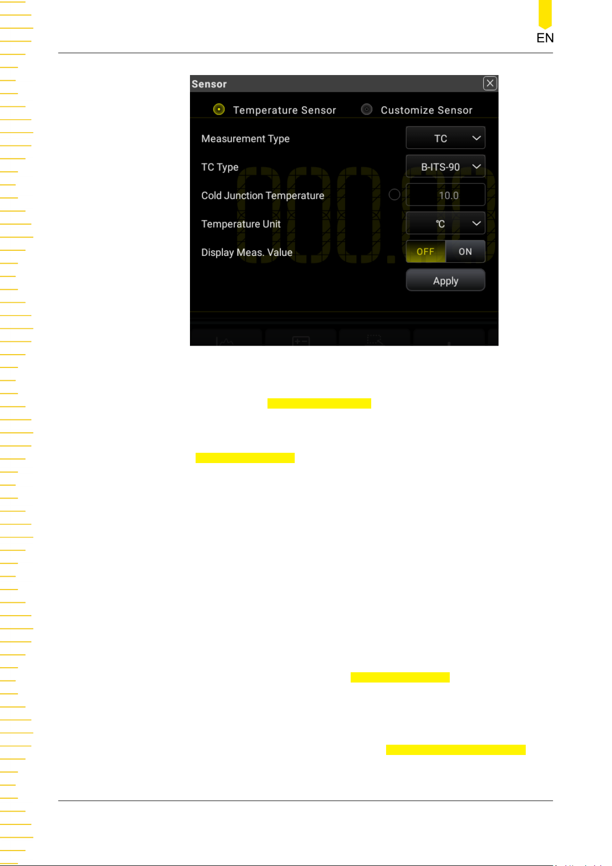
Front Panel Operation
Figure 5.28 Temperature Sensor Setting Interface
In
Figure 5.28
, click or tap Temperature Sensor to enter the temperature sensor
setting interface.
Select the temperature sensor type. As shown in
down list of
Measurement Type to select "TC", "RTD", or "Therm". By default, TC is
Figure 5.28
, click or tap the drop-
selected.
• TC
- The TC (thermocouple) is one of the most commonly used industrial
temperature detection device. It converts the temperature value into
voltage reading, and has a very large temperature measurement range.
The common thermocouples are B (Pt Rh 30- Pt Rh6), E (NI CR-WRCK), J
(Fe-WRCK), K (NI CR-NiSi), N (NiCrNi-NiSi), R (Pt Rh13 -Pt), S (Pt Rh10-Pt)
and T (Cu-WRCK). Among them, B, R and S are precious metal
thermocouple, while E, J, K, N and T are cheap metal thermocouples. For
the reference table about each thermocouple, please see the ITS-90
standards. By default, B-ITS-90 is selected.
DM858 Series User Guide
60
Click or tap the drop-down list of
Measurement Type to select "TC".
- User-defined Cold Junction Temperature
- Enables or disables the user-defined cold junction temperature. If the
option box before the input field of
Copyright ©RIGOL TECHNOLOGIES CO., LTD. All rights reserved.
Cold Junction Temperature is
Page 73

Front Panel Operation
not checked, the input field is grayed out and disabled. You can only
use the built-in cold junction temperature.
- If checked, click or tap the input field of Cold Junction Temperature,
then input the user-defined value with the pop-up numeric keypad.
NOTE
Theoretically, TC is measured at 0°C at the cold side. However, the instrument is
usually at room temperature during measurement rather than 0°C.
This has caused the thermopotential difference to decrease, resulting in
measurement inaccuracy or error.
Therefore, it is necessary to make the cold-junction compensation to reduce the
error.
- Temperature Unit: sets the temperature unit. The available units are ℃, ℉,
and K. By default, the unit is ℃.
- Display Meas. Value:
enables or disables the display of the measurement value on the screen.
- ON: enables the display of the measurement value on the screen.
- OFF: disables the display of the measurement value on the screen.
- Apply
Click or tap Apply to apply the current setting.
• RTD
- RTD is a temperature detector commonly used in medium-low
temperature range. It features in high measurement accuracy and stable
performance.
It measures the temperature depending on the changing resistance of the
measured substance with the temperature. The multimeter will display the
temperature corresponding to the resistance when the resistance changes.
This kind of sensor has good linearity.
The multimeter adopts the approximate arithmetic of IEC751 standards
and converts the resistance signal from the temperature sensor into the
related temperature for displaying.
For the reference table about each RTD, please refer to the related
standards.
Copyright ©RIGOL TECHNOLOGIES CO., LTD. All rights reserved. DM858 Series User Guide
61
Page 74
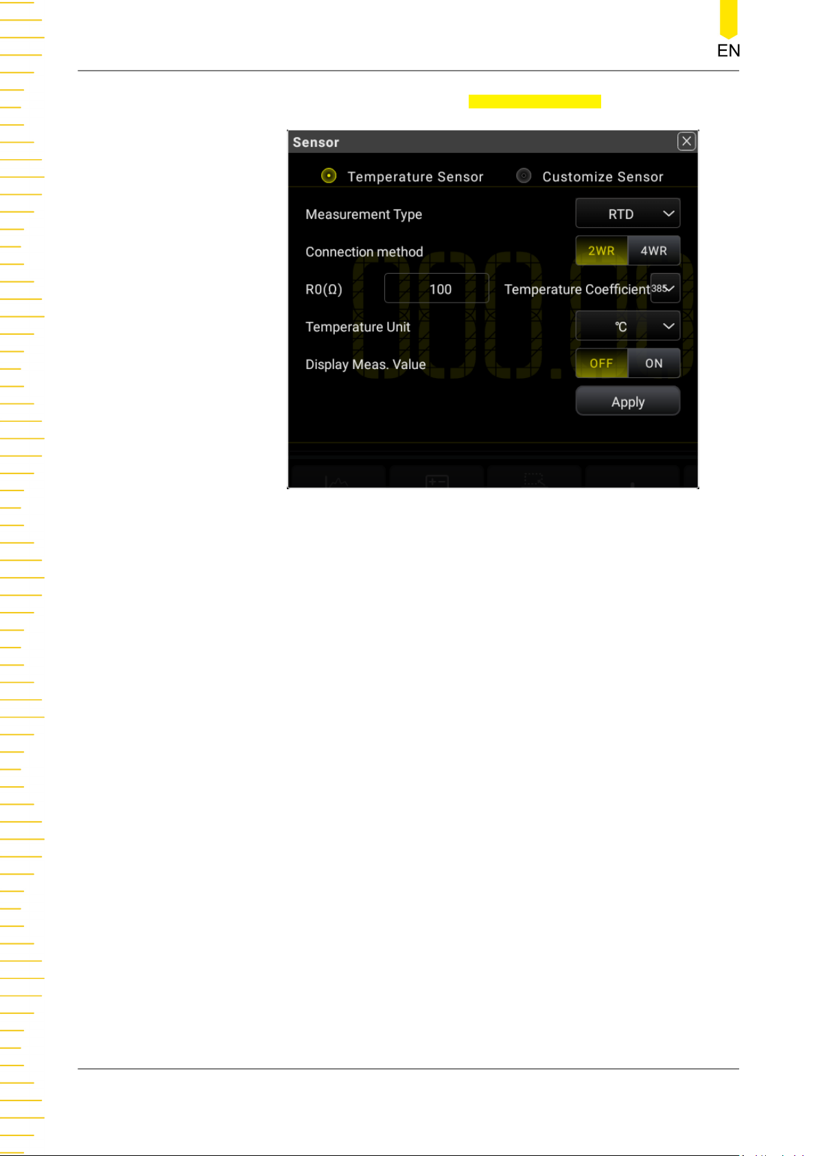
Front Panel Operation
Click or tap the drop-down list of Measurement Type to select "RTD".
Figure 5.29 RTD Temperature Sensor Setting Interface
- Connection Method: sets the connection method of the thermal
resistance. You can click or tap 2WR or 4WR to select the connection
method. By default, it is 2WR.
- R0(Ω): sets the nominal resistance at the reference temperature T0.
The settable range is from 49 Ω to 2,100 Ω. By default, it is 100 Ω.
- Temperature Unit: sets the temperature unit. The available units are
℃, ℉, and K. By default, the unit is ℃.
- Temperature Coefficient: sets the temperature coefficient used for
the RTD. Calculate it according to the formula: (R100 - R0)/R0.
Wherein, R100 indicates the resistance at temperature 100℃. The
available temperature coefficient values are 385, 389, 391, and 392. By
DM858 Series User Guide
62
default, it is 385.
- Display Meas. Value:
enables or disables the display of the measurement value on the
screen.
Copyright ©RIGOL TECHNOLOGIES CO., LTD. All rights reserved.
Page 75
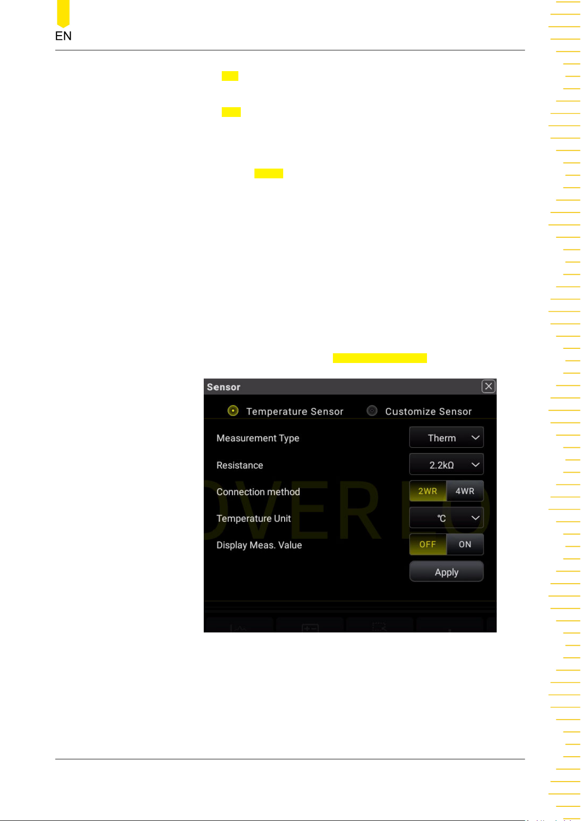
Front Panel Operation
- ON: enables the display of the measurement value on the
screen.
- OFF: disables the display of the measurement value on the
screen.
- Apply
Click or tap Apply to apply the current setting.
• Therm
- The THERM (thermistor) converts the temperature variation information
into resistance variation information. It is especially sensitive to
temperature.
In this measurement, the multimeter adopts Steinhart-Hart approximate
arithmetic and converts the resistance signal from the temperature sensor
into the related temperature for displaying.
To use the THERM sensor, you need to set the resistance parameter of the
multimeter and select the connection mode.
Click or tap the drop-down list of
Measurement Type to select "Therm".
Figure 5.30 Therm Temperature Sensor Setting Interface
- Resistance: sets the resistance at temperature 25℃. The available
choices are 2.2 kΩ, 3 kΩ, 5 kΩ, 10 kΩ, and 30 kΩ. By default, it is 2.2
kΩ.
Copyright ©RIGOL TECHNOLOGIES CO., LTD. All rights reserved. DM858 Series User Guide
63
Page 76
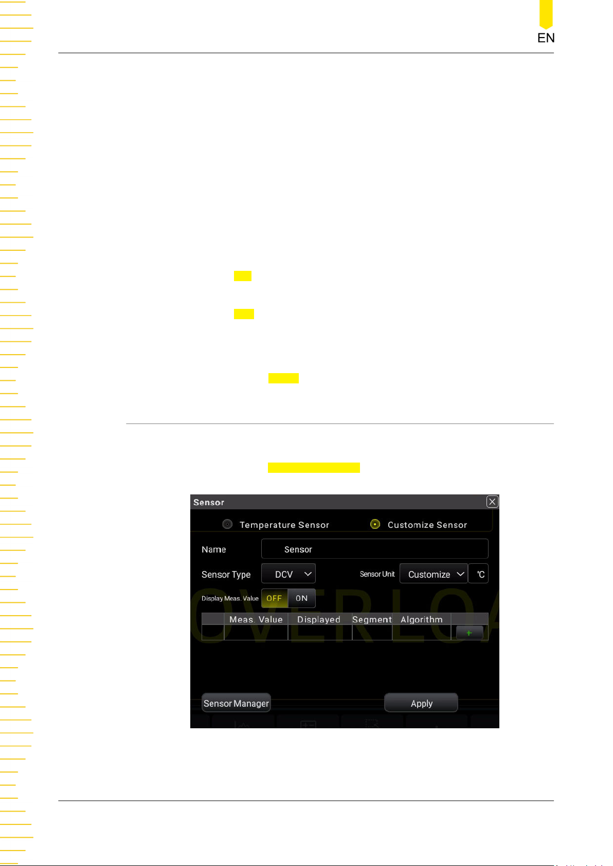
Front Panel Operation
- Connection Method: sets the connection method of the thermal
resistance. You can click or tap 2WR or 4WR to select the connection
method. By default, it is 2WR.
- Temperature Unit: sets the temperature unit. The available units are
℃, ℉, and K. By default, the unit is ℃.
- Display Meas. Value:
enables or disables the display of the measurement value on the
screen.
- ON: enables the display of the measurement value on the
screen.
- OFF: disables the display of the measurement value on the
screen.
- Apply
Click or tap Apply to apply the current setting.
5.3.10.2 To Measure User-defined Sensor
Set the User-Defined Sensor
In
Figure 5.28
, click or tap Customize Sensor to enter the user-defined sensor
setting interface.
DM858 Series User Guide
64
Figure 5.31 User-defined Sensor Setting Interface
Copyright ©RIGOL TECHNOLOGIES CO., LTD. All rights reserved.
Page 77
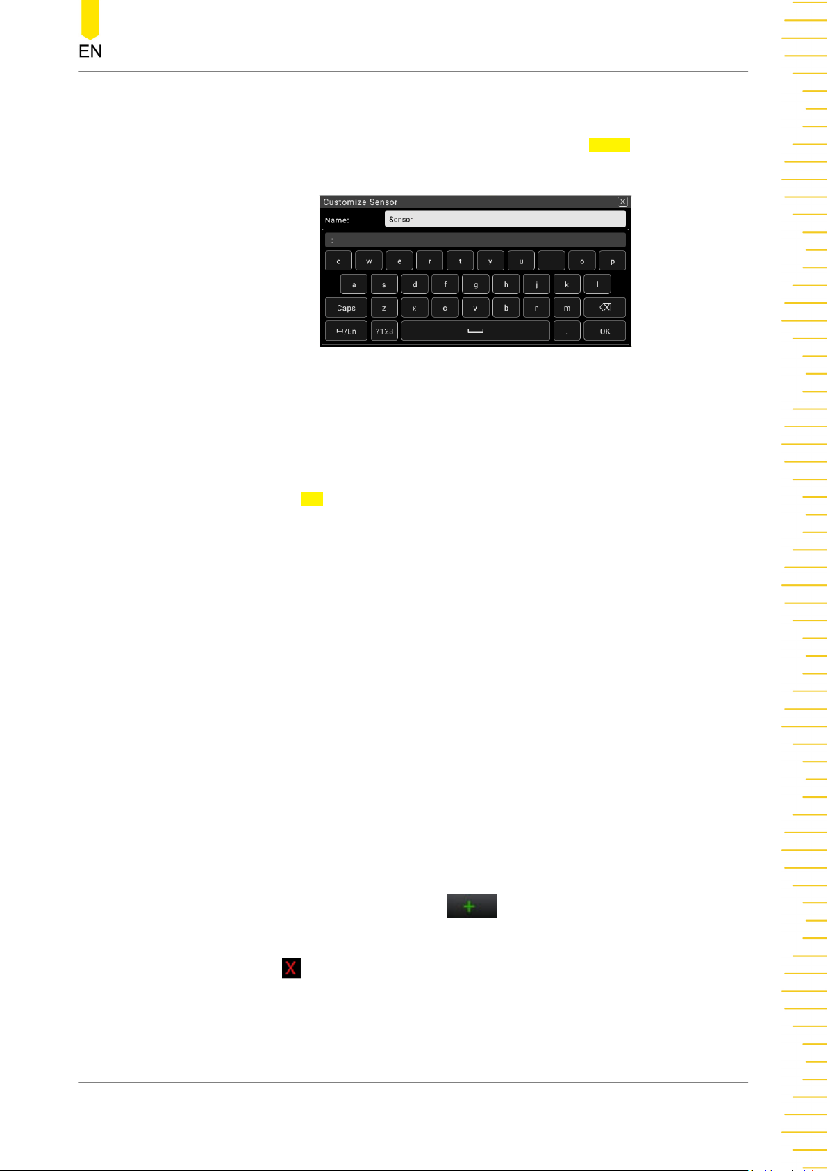
Front Panel Operation
1. Name
Sets the name of the sensor. Click or tap the input field of Name to enter the
name setting interface.
Figure 5.32 User-defined Sensor Name Setting
a. Input the sensor name. The length of the name shall not exceed 15 characters
and cannot be the same as the existing sensor name.
b. Click or tap OK to confirm input.
2. Sensor Type
Sets the sensor type. The available sensors are DCV, DCI, 2WR, 4WR, FREQ, and
TC. By default, it is DCV.
3. Sensor Unit
Sets the sensor unit. The available units are ℃ (degree Celsius), ℉(degree
Fahrenheit), K, %, °(degree), and Customize. By default, it is °. When you select
"Customize", click or tap the edit field next to the Customize field, then a virtual
keypad is displayed. Input the user-defined unit with the virtual keypad.
4. Display Meas. Value
Enables or disables the display of the measurement value on the screen.
- ON: enables the display of the measurement value on the screen.
- OFF: disables the display of the measurement value on the screen.
5.
Reference Value
Sets the reference value. Click or tap
to enter the reference value setting
interface.
Click or tap to delete the specified line of the reference values.
Copyright ©RIGOL TECHNOLOGIES CO., LTD. All rights reserved. DM858 Series User Guide
65
Page 78
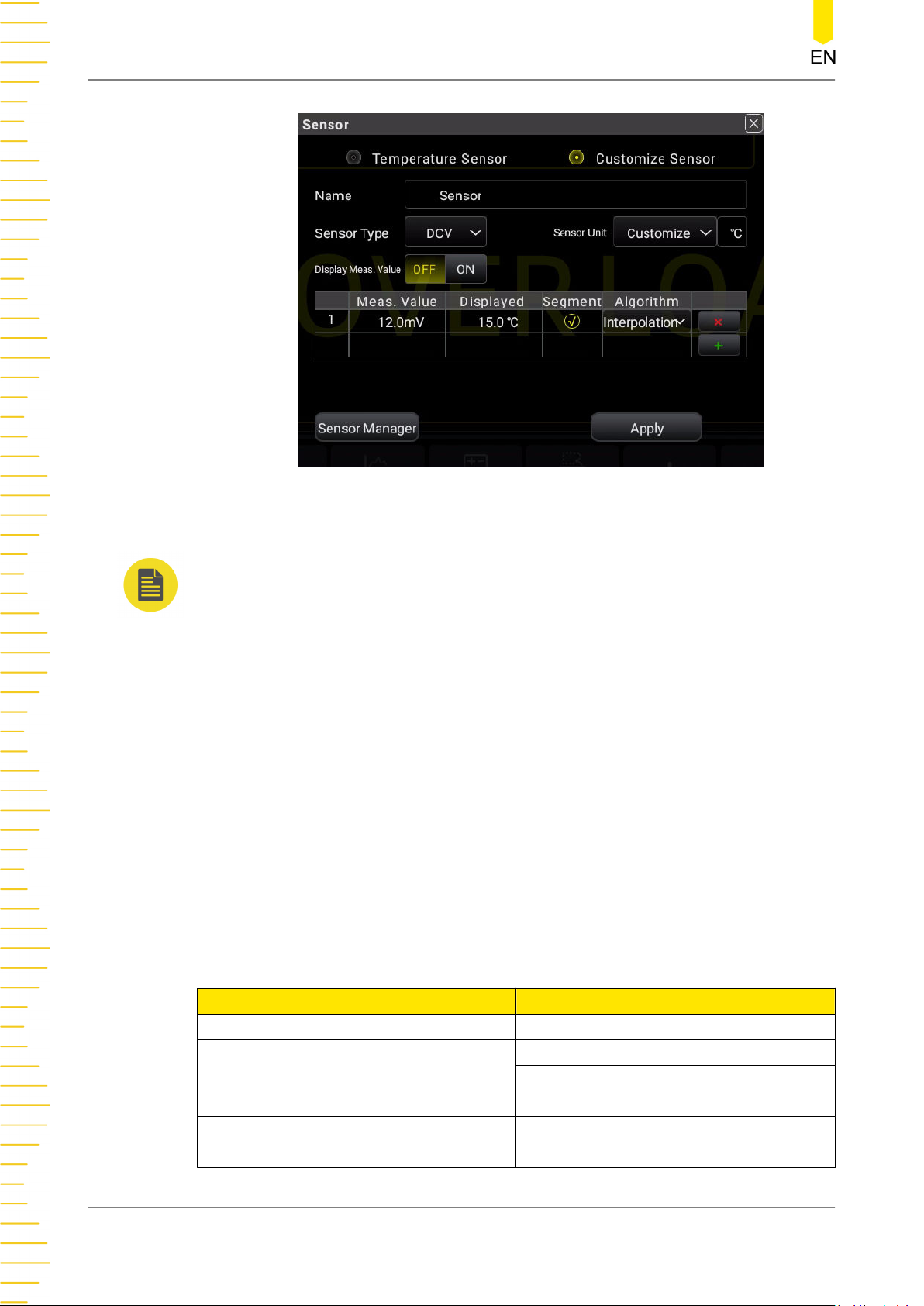
Front Panel Operation
Figure 5.33 Reference Value Setting Table
NOTE
Algorithm: The reference value calculation supports interpolation and fitting algorithms.
The interpolation algorithm applies to the sensor that has a strong linear relationship, and
the number of data groups to be calculated shall not be less than two. The fitting
algorithm applies to the sensor that has no distinctive linear relationship, and the number
of data groups to be calculated shall not be less than 5 groups of measured values and
displayed values.
Segment: sets the segment status of the data group. You can enable or disable the
segment display. By default, segment is enabled for the first group of reference value and
cannot be disabled. If you add another group of reference value, you can select whether to
enable or disable the segment. Only when you enabled the segment, can you set the
algorithm method for the current data group.
- Meas. Value: indicates the actually measured value. Its range is determined by
the sensor type. For details, refer to the following table.
Table 5.12 Meas. Value Setting Range
Sensor Type Setting Range
DCV -1000 V to +1000 V
DCI -10 A to +10 A (DM858)
2WR 0 Ω to +50 MΩ
4WR 0 Ω to +50 MΩ
Freq 20 Hz to 100 kHz
DM858 Series User Guide
66
-3 A to +3 A (DM858E)
Copyright ©RIGOL TECHNOLOGIES CO., LTD. All rights reserved.
Page 79
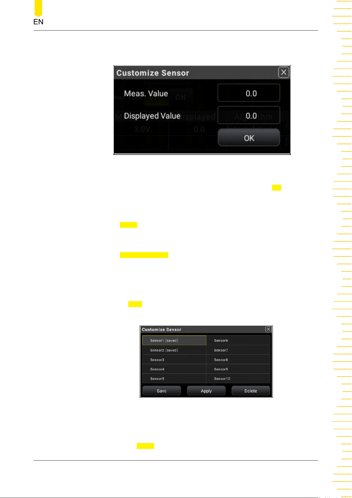
Front Panel Operation
- Displayed Value: indicates the displayed value of the sensor. The settable
range is from -999999 to +999999.
Figure 5.34 Reference Value Setting
After setting the measured value and displayed value, click or tap OK to confirm
the reference value setting, as shown in the figure below.
6. Apply the setting
Click or tap Apply to apply the current setting.
7. Sensor management
Click or tap Sensor Manager to enter the user-defined sensor setting interface.
The instrument supports at most 10 user-defined sensors. Each time only one
sensor can be selected.
- Save the Sensor
Click or tap
Save to save the selected sensor. After being saved, "saved" in
bracket is added following the saved sensor name.
Figure 5.35 Customize the Sensor
- Apply the Sensor
1. Click or tap Apply to apply the user-defined sensor setting.
Copyright ©RIGOL TECHNOLOGIES CO., LTD. All rights reserved. DM858 Series User Guide
67
Page 80
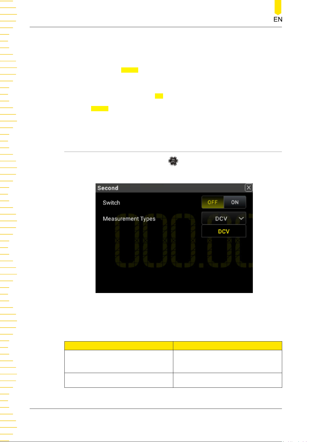
Front Panel Operation
2. This operation is only available for the saved user-defined sensor.
- Delete the Sensor
1. Click or tap Delete to delete the user-defined sensor.
2. Then a dialog box is displayed, prompting you to confirm whether to delete
the selected sensor. Click OK to confirm deleting the selected sensor; click
Cancel to cancel the deletion operation. The deletion operation is only
available for the saved user-defined sensor.
5.4 2ND Measurement
Click or tap the function navigation icon at the lower-left corner of the screen,
and then select 2ND to enter the secondary measurement setting menu.
Figure 5.36 2ND Measurement Setting Interface
Table 5.13 2ND Measurement Parameter Setting
Parameter Description
Switch
Measurement Types Selects the type of 2ND measurement.
DM858 Series User Guide
68
Enables or disables the 2ND
measurement function.
Copyright ©RIGOL TECHNOLOGIES CO., LTD. All rights reserved.
Page 81
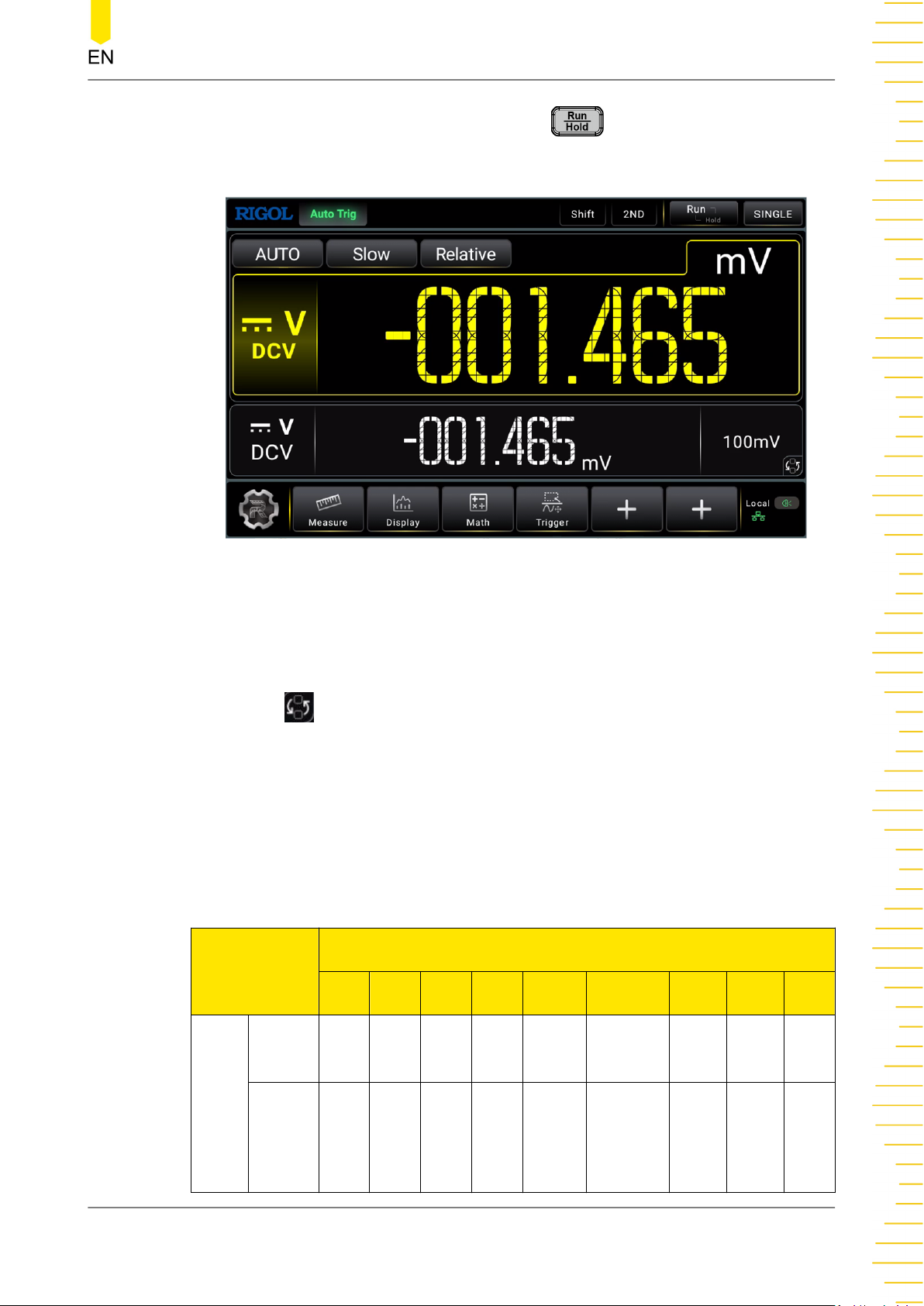
Front Panel Operation
When you enable the 2ND measurement, press , the results of the 2ND
measurement is displayed in the secondary display area of the screen, as shown in the
following figure.
Figure 5.37 Main and Secondary Display Areas
As shown in the figure above, the section where the measured item and values are
displayed in yellow is considered as the main display area, and the section below the
main display area is considered as the secondary display area.
Click or tap
measurement item and the secondary measurement item. For details, refer to
Interface Overview
in the secondary display area to switch the position of the basic
User
.
The basic measurement types displayed in the main display area are all supported by
the 2ND measurement. In some specific conditions, some of the basic measurement
types are disabled for 2ND measurement. For details, see the table below.
Table 5.14 Basic Measurement Types and 2ND Measurement Types
Basic Measurement Function
DCV DCI ACV ACI FREQ PERIOD 2WR 4WR Cap
2ND
Meas.
DCV
Avail
able
Types
DCI
Copyright ©RIGOL TECHNOLOGIES CO., LTD. All rights reserved. DM858 Series User Guide
Avail
able
69
Page 82
Front Panel Operation
Basic Measurement Function
DCV DCI ACV ACI FREQ PERIOD 2WR 4WR Cap
ACV
ACI
FREQ
PERIOD
2WR
4WR
Cap
Avail
able
Avail
able
Avail
able
Avail
able
Avail
able
Avail
able
Availa
ble
Availa
ble
Available
Available
Availa
ble
Availa
ble
Avail
able
Remarks:
1. If the measurement type for the basic measurement and 2ND measurement is the
same:
- The measurement data are updated synchronously in both the main display
area and the secondary display area.
- If the math operations are adopted for the basic measurement types, then the
operation results are displayed in the main display area and the measurement
values before the operation are displayed in the secondary display area. For
details, refer to
User Interface Overview
.
2. If the measurement type for the basic measurement and 2ND measurement is
different:
- The two types of measurements are carried out alternatively. The measurement
data in the main display area and the secondary display area are updated
respectively.
- If math operations such as Stat, Limit, dBm, and dB are adopted and Relative
operation is disabled for the basic measurement types, then the measurement
values for the main measurement types are displayed in the main display area
and the measurement values for the secondary measurement types are
displayed in the secondary display area.
DM858 Series User Guide
70
Copyright ©RIGOL TECHNOLOGIES CO., LTD. All rights reserved.
Page 83
Front Panel Operation
- If the math operations such as Stat, Limit, dBm, and dB are adopted and
Relative operation is enabled for the basic measurement types, then the
Relative operation results are displayed in the main display area and the
measurement values for the secondary measurement types are displayed in the
secondary display area.
3. When the basic measurement type is Sensor, after setting the sensor parameters,
the operation results (Relative Value) of the sensor is displayed in the main display
area, and the current measurement value is displayed in the secondary display
area. For details, refer to
4. When the basic measurement type is ACV and the secondary measurement type is
FREQ/PERIOD; or when the basic measurement type is FREQ/PERIOD and the
secondary measurement type is ACV, the measurement values are mainly displayed
for the basic measurement types.
5. By default, the secondary measurement types adopts Auto range. If the main and
secondary measurement types are the same, then the secondary measurement
type use the same range as the basic meaurement type.
6. The measurement data of the secondary measurement types do not support
Holding operation.
5.5 Preset Mode
To Measure User-defined Sensor
.
The instrument provides the preset setting. Preset mode applies to production lines
to avoid misoperations.
Press > to enter the preset interface.
Copyright ©RIGOL TECHNOLOGIES CO., LTD. All rights reserved. DM858 Series User Guide
71
Page 84
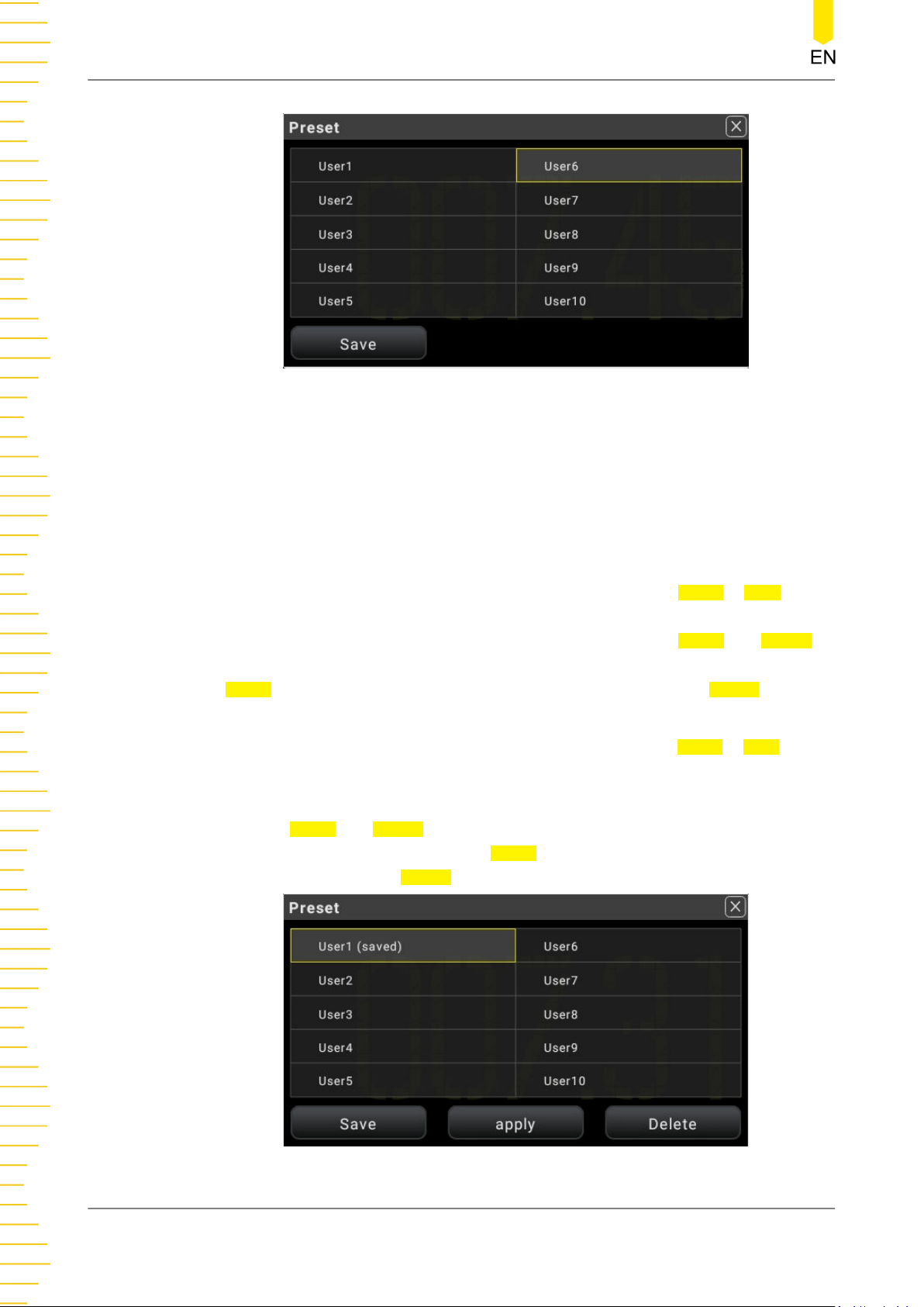
Front Panel Operation
The preset mode allows you to preset 10 user-defined settings.
Figure 5.38 Preset Interface
Preset Settings
If User1 is defined to preset DCV measurement configurations and User2 is defined to
preset ACV measurement configurations:
After configuring the DCV measurement parameters, click or tap User1 > Save,
"saved" in brackets is added following User1, which indicates that the DCV
configurations are saved as User1(saved) preset file. At this time,
Apply and Delete
menu are added to the interface. To load the DCV configurations that you set, click or
Apply to load the DCV measurement configurations. Click or tap Delete to delete
tap
the user-defined DCV presetting.
After configuring the ACV measurement parameters, click or tap
User2 > Save,
"saved" in brackets is added following User2, which indicates that the ACV
configurations are saved as User2(saved) preset file.
At this time,
configurations that you set, click or tap
Apply and Delete menu are added to the interface. To load the ACV
Apply to load the ACV measurement
configurations. Click or tap Delete to delete the user-defined ACV presetting.
DM858 Series User Guide
72
Figure 5.39 Preset Setting Interface
Copyright ©RIGOL TECHNOLOGIES CO., LTD. All rights reserved.
Page 85
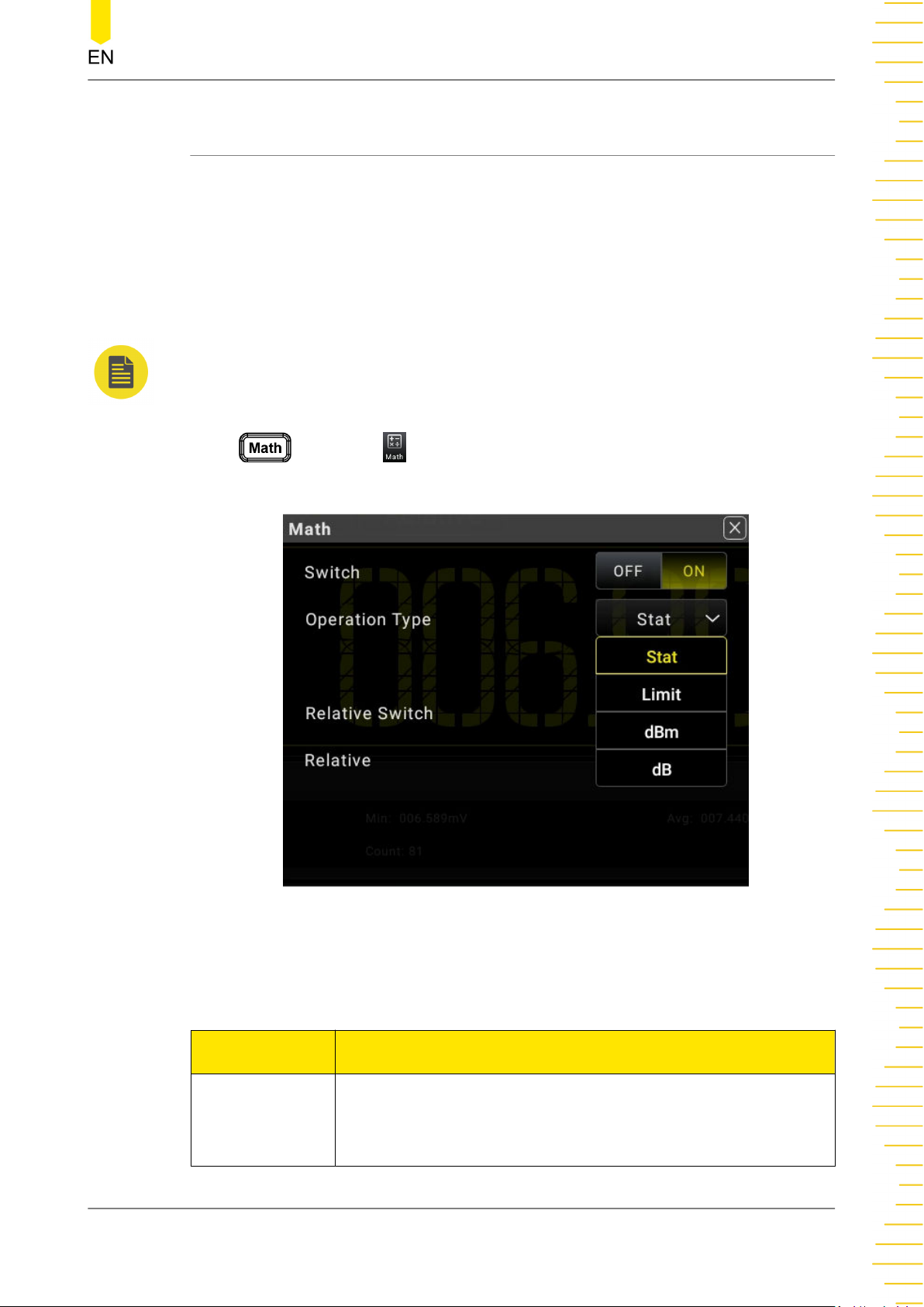
5.6 Math Operation
The multimeter provides five math functions: Statistics (Max, Min, Avg, standard
deviation, and count), Limit, dBm, dB, and Relative operation. You can select different
math functions for different measurement items.
The math operations are applicable to the voltage, current, resistance, capacitance,
frequency/period, and sensor measurements. However, dB and dBm operations are
only applicable to the voltage measurement.
NOTE
The math operation is diabled when the range is AUTO.
Press or click/tap on the screen, then the math operation interface is
displayed, as shown in
Figure 5.40
Front Panel Operation
.
Figure 5.40 Math Operation Setting
Table 5.15 Description of Math Operations
Parameter Remarks
Makes statistics of the current measurement, including maximum
Statistics
Copyright ©RIGOL TECHNOLOGIES CO., LTD. All rights reserved. DM858 Series User Guide
value, minimum value, average value, standard deviation, and
count (current count of the samples).
73
Page 86
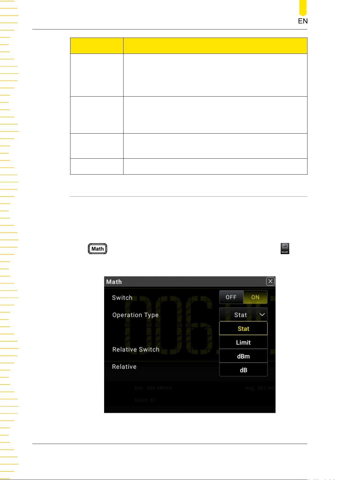
Front Panel Operation
Parameter Remarks
Limit
dBm
Sets the upper and lower limits and makes limit operation to
identify those signals that are beyond the limits by sounding an
alarm. It is applicable to DCV, ACV, DCI, ACI, Resistance,
Frequency, Capacitance, and temperature measurements.
The dBm function is logarithmic, comparing power delivered to a
reference resistance,
relative to 1 milliwatt:
dB
Relative Enables or disables the Relative operation.
5.6.1 Statistics
The Statistics operation calculates the min. value, max. value, average value, standard
deviation, and reading count during the measurement.
The multimeter can perform Statistics operation on the following measurement items:
DCV, ACV, DCI, ACI, Resistance, Frequency, Period, Capacitance, and any sensors.
Press
enter the math operation interface. Then, select Stat from the drop-down list of
Operation Type.
Each dB measurement is the difference between the input signal
and a stored reference value, with both values converted to dBm.
to enter the math operation interface. You can also click or tap to
DM858 Series User Guide
74
Figure 5.41 Statistic Parameter Setting
Copyright ©RIGOL TECHNOLOGIES CO., LTD. All rights reserved.
Page 87
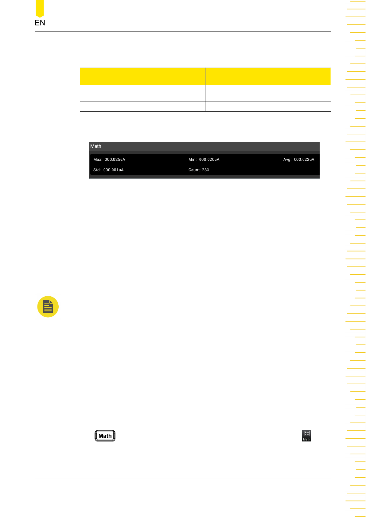
Table 5.16 Statistic Parameter Setting
Parameter Remarks
Front Panel Operation
Switch
Enables or disables the Statistical
operation.
Operation Type Selects Stat.
The operation results are displayed in the secondary display area, as shown in the
following figure.
Figure 5.42 Statistics Operation Result
• Max: indicates the max. reading.
• Min: indicates the min. reading.
• Avg: indicates the average value of the reading.
• Std: indicates the standard deviation of the reading.
• Count: indicates the reading count.
NOTE
• When statistics operation is selected, the multimeter takes the first reading as the
• The max. value, min. value, average value, and sample count are all stored in the volatile
5.6.2 Limit
The limit operation allows you to set the specified upper limit and lower limit. Once
the signal beyond the set limits appears, the beeper sounds. The multimeter can
perform limit operation on the following measurement items: DCV, ACV, DCI, ACI,
Resistance, Frequency, Period, Capacitance, and temperature sensor.
Press to enter the math operation interface. You can also click or tap to
enter the math operation interface. Then, select Limit from the drop-down list of
Operation Type.
maximum (or minimum) for displaying. The reading shown on the screen is always the
maximum (or minimum) within the current readings when measuring multiple
consecutive readings.
memory. They will be cleared at power-off.
Copyright ©RIGOL TECHNOLOGIES CO., LTD. All rights reserved. DM858 Series User Guide
75
Page 88
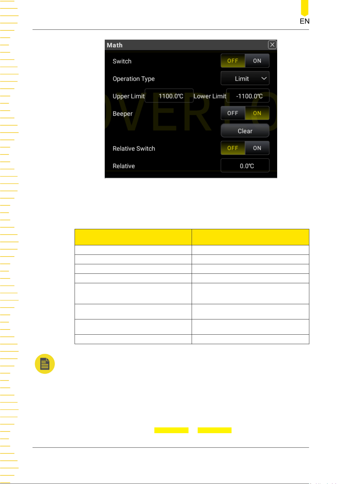
Front Panel Operation
Figure 5.43 Limit Parameter Setting
Table 5.17 Limit Parameter Setting
Parameter Remarks
Switch Enables or disables the Limit operation.
Operation Type Selects Limit operation.
Upper Limit Indicates the specified upper limit.
Lower Limit Indicates the specified lower limit.
Enables or disables the beeper. When
Beeper
enabled, the beeper sounds once the
reading exceeds the set limits.
Clear
Relative Switch
Clears the current status and starts to
make statistics again.
Enables or disables the Relative
operation.
Relative Input the Relative value.
NOTE
• The ranges of the upper and lower limits shall be within -120%-120% of the current
measurement range.
• The specified upper limit shall be greater than the lower limit.
• The upper and lower limits are stored in the volatile memory. They will be reset to the
default values at power-on.
1. Set the limits
Click/tap the input field of Upper Limit or Lower Limit to input the desired value
with the pop-up numeric keypad.
DM858 Series User Guide
76
Copyright ©RIGOL TECHNOLOGIES CO., LTD. All rights reserved.
Page 89
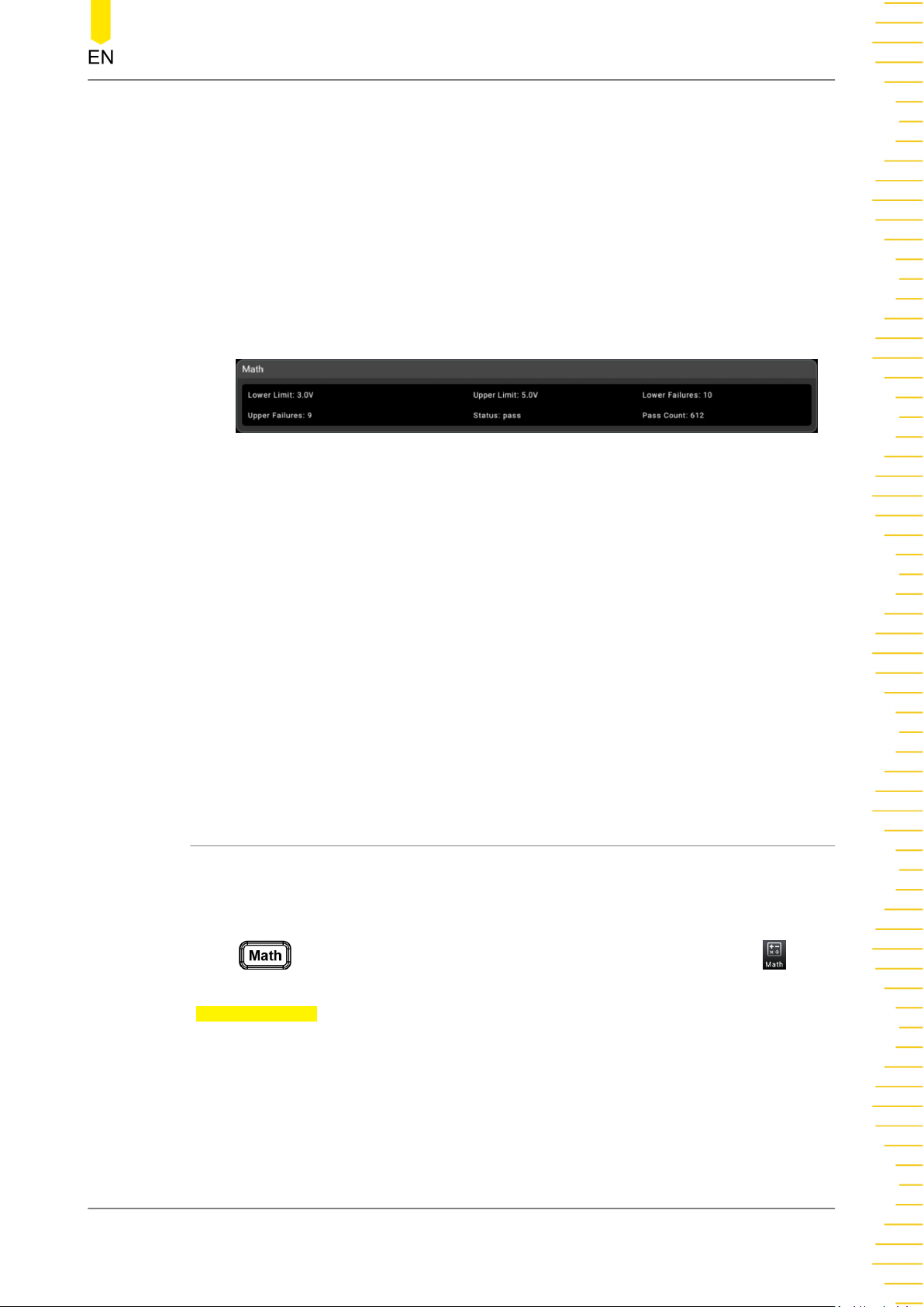
Front Panel Operation
When inputting a positive or negative value, click or tap the "±" sign to switch
between the positive and negative value sign.
The limit value unit is determined by the currently selected measurement item.
When the limit value you set exceeds the specified one, the beeper sounds (if
enabled), and an error message "-222 Data out of range" is displayed.
2. Math operation result display
When you perform the math operation, the math operation results are displayed in
the secondary display area, as shown in the figure below.
Figure 5.44 Limit Operation
Lower Failures: indicates the counts of below the defined lower limit.
Upper Failures: indicates the counts of above the defined upper limit.
Status: indicates the status of the limit operation.
Pass count: indicates the counts of values that are within the defined upper limit
and lower limit.
When the count exceeds the upper limit, the secondary display area displays "high
fail"; when the count exceeds the lower limit, the secondary display area displays
"low fail"; when the count does not exceed the upper limit or lower limit, it shows
"pass". If the beeper is enabled, when the count exceeds the upper limit or is
below the lower limit, the beeper sounds an alarm.
5.6.3 dBm
dBm represents the absolute value of the power. The dBm operation calculates the
power of the reference resistance according to the measured voltage. The dBm
function applies to AC voltage and DC voltage measurements only.
Press to enter the math operation interface. You can also click or tap to
enter the math operation interface. Then, select dBm from the drop-down list of
Operation Type.
Copyright ©RIGOL TECHNOLOGIES CO., LTD. All rights reserved. DM858 Series User Guide
77
Page 90
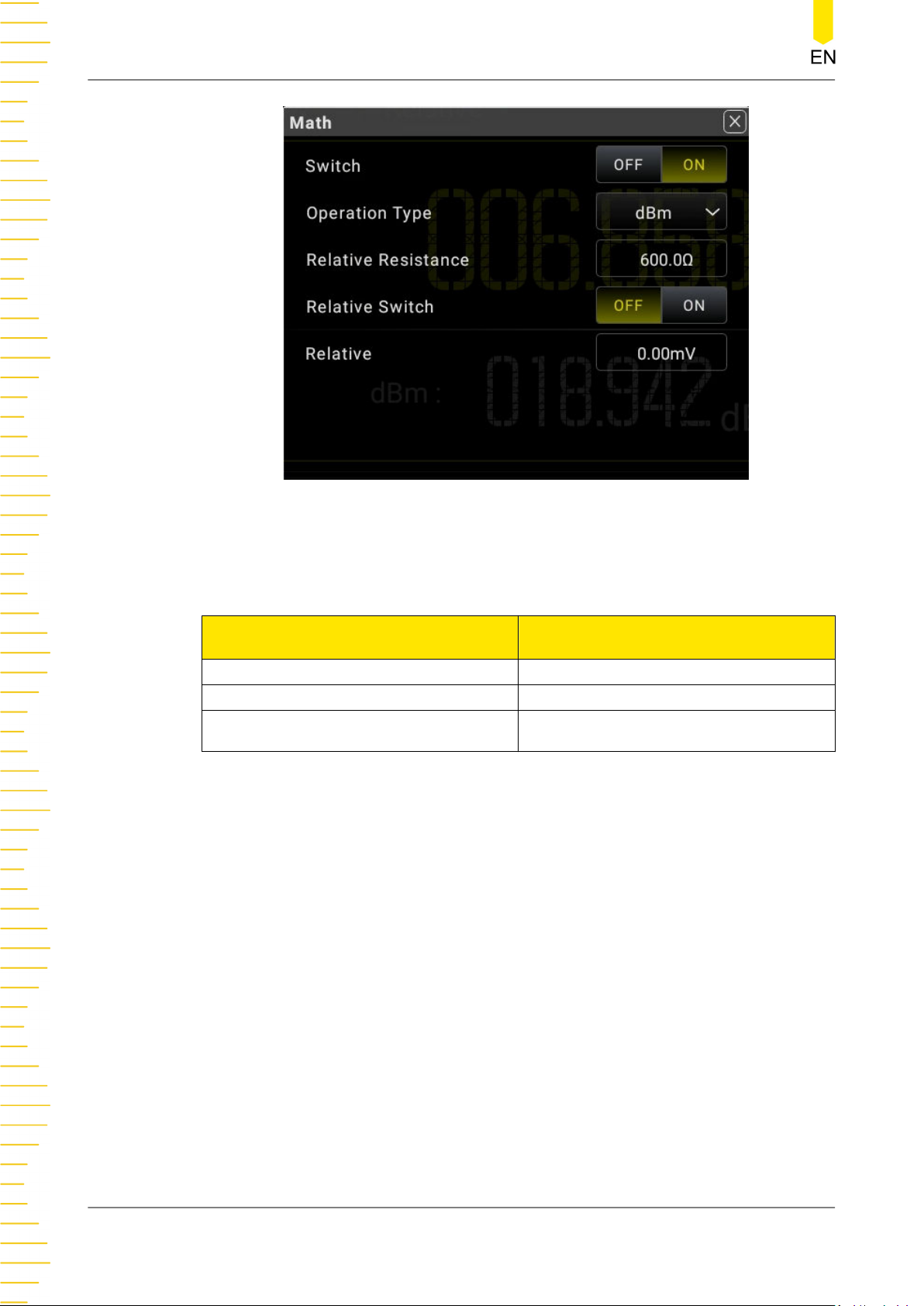
Front Panel Operation
Figure 5.45 dBm Parameter Setting Interface
Table 5.18 dBm Parameter Setting
Parameter Description
Switch Enables or disables dBm operation.
Operation Type Selects dBm.
Relative Resistance
The settable range is from 50 Ω to 8000
Ω.
dBm Operation Method
The dBm operation calculates the power of the reference resistance according to the
measured voltage. The formula is as follows:
dBm = 10 x Log10 [(Reading2 /R
Wherein, Reading denotes the measured voltage and R
)/0.001W]
REF
denotes the reference
REF
resistance.
Take DCV measurement as an example, the calculation results are displayed in the
secondary display area, as shown in the following figure.
DM858 Series User Guide
78
Copyright ©RIGOL TECHNOLOGIES CO., LTD. All rights reserved.
Page 91
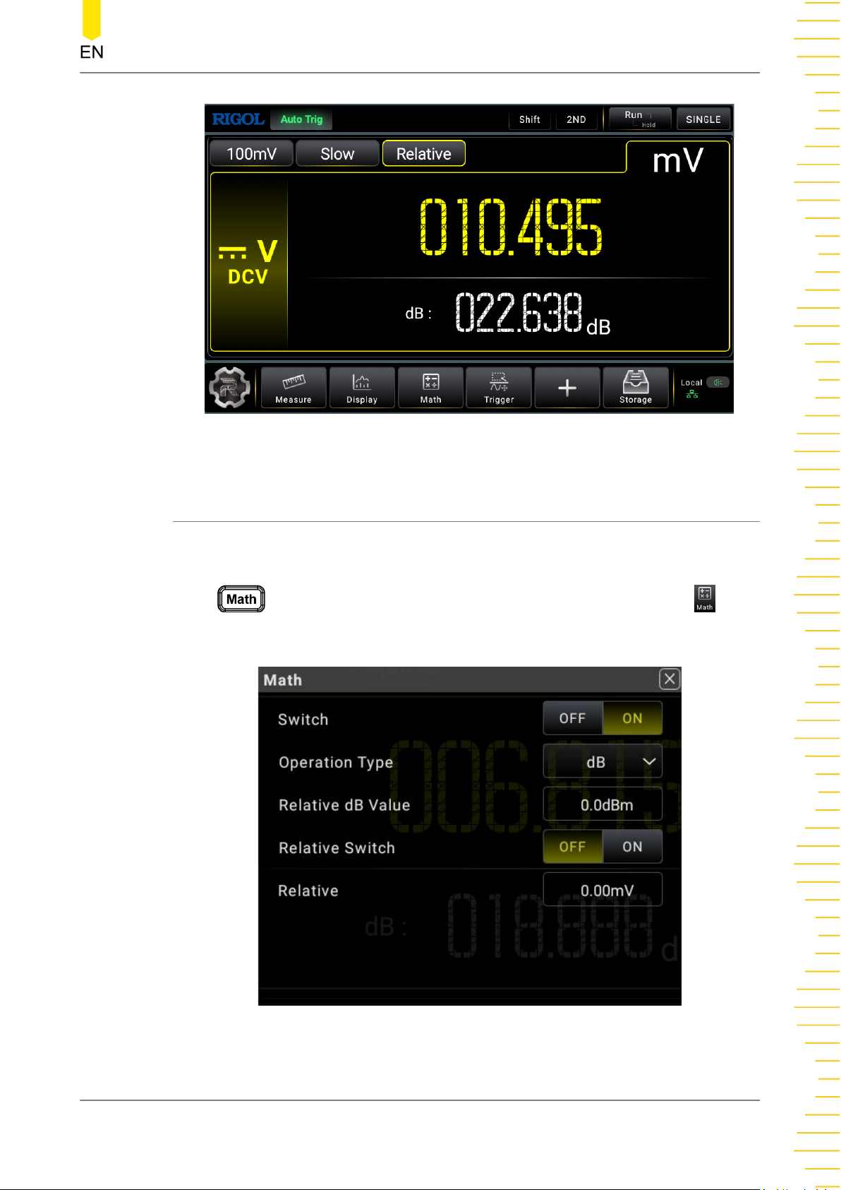
Front Panel Operation
5.6.4 dB
dB represents the relative value which is used in the Relative operation of dBm value.
The dB function applies to AC voltage and DC voltage measurements only.
Press to enter the math operation interface. You can also click or tap to
enter the math operation interface. Then, select dB from the drop-down list of
Operation Type.
Figure 5.46 dBm Operation Results
Figure 5.47 dB Operation Parameter Setting
Copyright ©RIGOL TECHNOLOGIES CO., LTD. All rights reserved. DM858 Series User Guide
79
Page 92
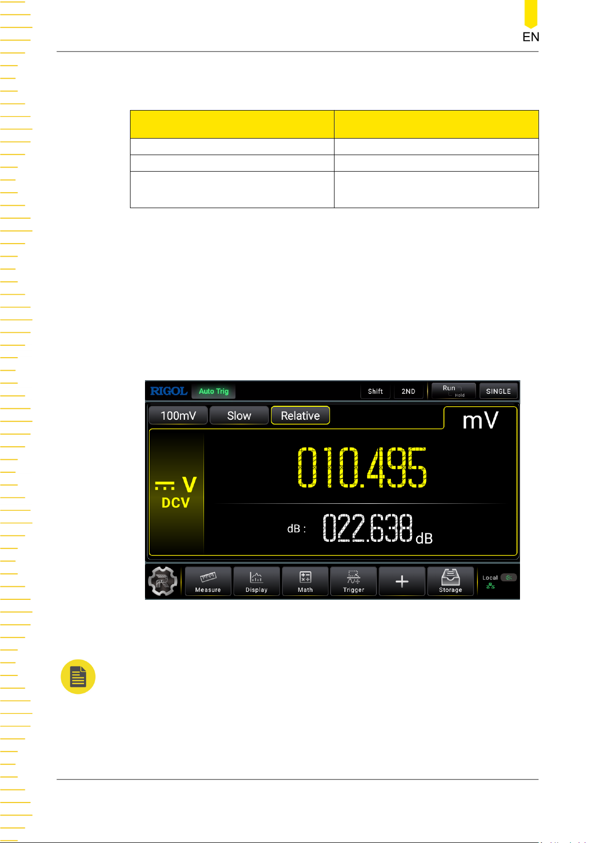
Front Panel Operation
Table 5.19 dB Parameter Setting
Parameter Description
Switch Enables or disables dB operation.
Operation Type Selects dB.
Relative dB Value
dB Operation Method
When enabled, the multimeter calculates the dBm value of the next reading and
subtracts the relative dB value from this value and then displays the result.
= 10 x Log10 [(Reading2 /R
dB
The range of the relative dB value is from
-120.00 dBm to 120.00 dBm. By default,
it is 0 dBm.
)/0.001W] - dB relative value
REF
Wherein, Reading denotes the measured voltage and R
denotes the reference
REF
resistance.
Take DCV measurement as an example, the calculation results are displayed in the
secondary display area, as shown in the following figure.
NOTE
Relative dB Value
• Input a relative dB value with a pop-up numeric keypad, and save it as a relative dB value.
• The relative dB value is stored in the volatile memory and will be cleared at power-off.
DM858 Series User Guide
80
Figure 5.48 dB Operation Results
The range of the relative dB value is from -120 dBm to 120 dBm. By default, it is 0 dB.
Copyright ©RIGOL TECHNOLOGIES CO., LTD. All rights reserved.
Page 93
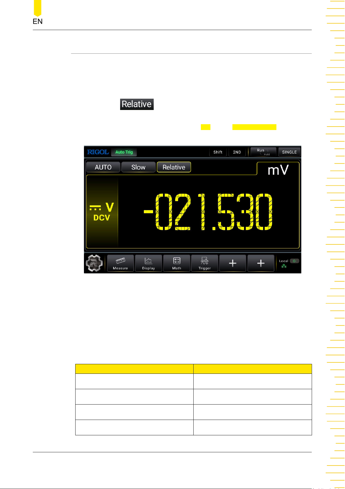
5.6.5 Relative
The reading displayed on the screen in Relative operation is the difference between
measured and relative values.
Enable the relative operationTo enable the relative operation, perform the following
operations:
Front Panel Operation
• Click or tap
is highlighted in yellow box.
• In the math operation menu, click or tap ON for the Relative Switch menu.
Displayed Value = Measured Value - Relative Value
to enable the relative operation. The Relative menu label
Figure 5.49 Relative operation
The multimeter can perform relative operation on the following measurement items:
DCV, ACV, DCI, ACI, Resistance, Frequency, Period, Capacitance, and temperature
sensor.
The ranges of the relative values in Relative operation are shown in the table below:
Table 5.20 Relative Value Setting Range
Measurement Item Setting Range
DCV
ACV
DCI/ACI
2WR/4WR
(-120% of the current range) to (120% of
the current range)
(-120% of the current range) to (120% of
the current range)
(-120% of the current range) to (120% of
the current range)
(-120% of the current range) to (120% of
the current range)
Copyright ©RIGOL TECHNOLOGIES CO., LTD. All rights reserved. DM858 Series User Guide
81
Page 94
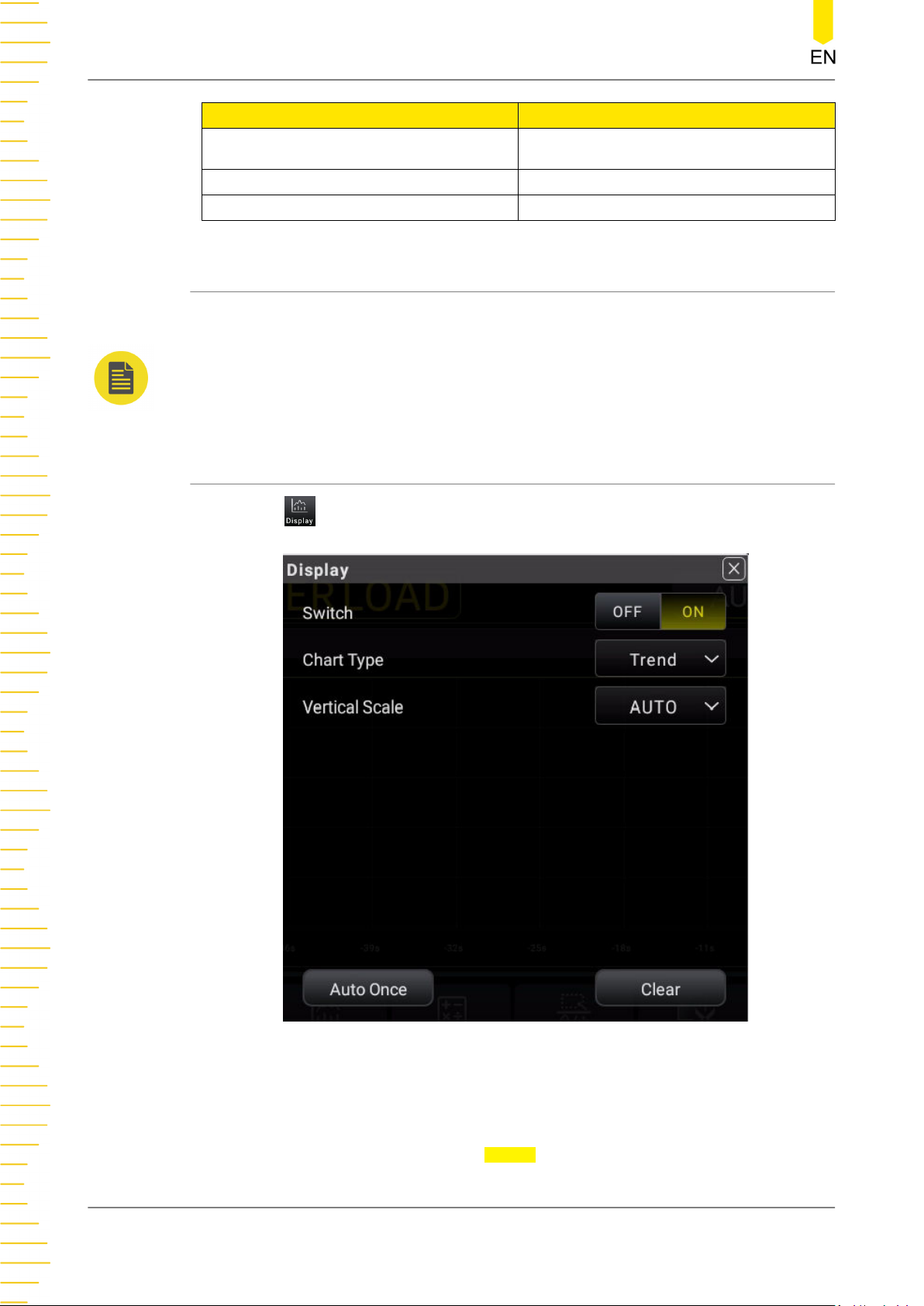
Front Panel Operation
Measurement Item Setting Range
Capacitance
Frequency -120 kHz to 120 kHz
Period -60 ms to 60 ms
5.7 Graph Display
The measurement results can be displayed in Trend, Histogram, and Bar Chart.
NOTE
The graph display is disabled in Continuity and Diode tests.
5.7.1 Trend Graph
(-120% of the current range) to (120% of
the current range)
Click or tap to enter the graph display interface.
1. Enable the graph
Click or tap the ON/OFF tab for the Switch menu to enable or disable the graph
display.
DM858 Series User Guide
82
Figure 5.50 Graph Display
Copyright ©RIGOL TECHNOLOGIES CO., LTD. All rights reserved.
Page 95
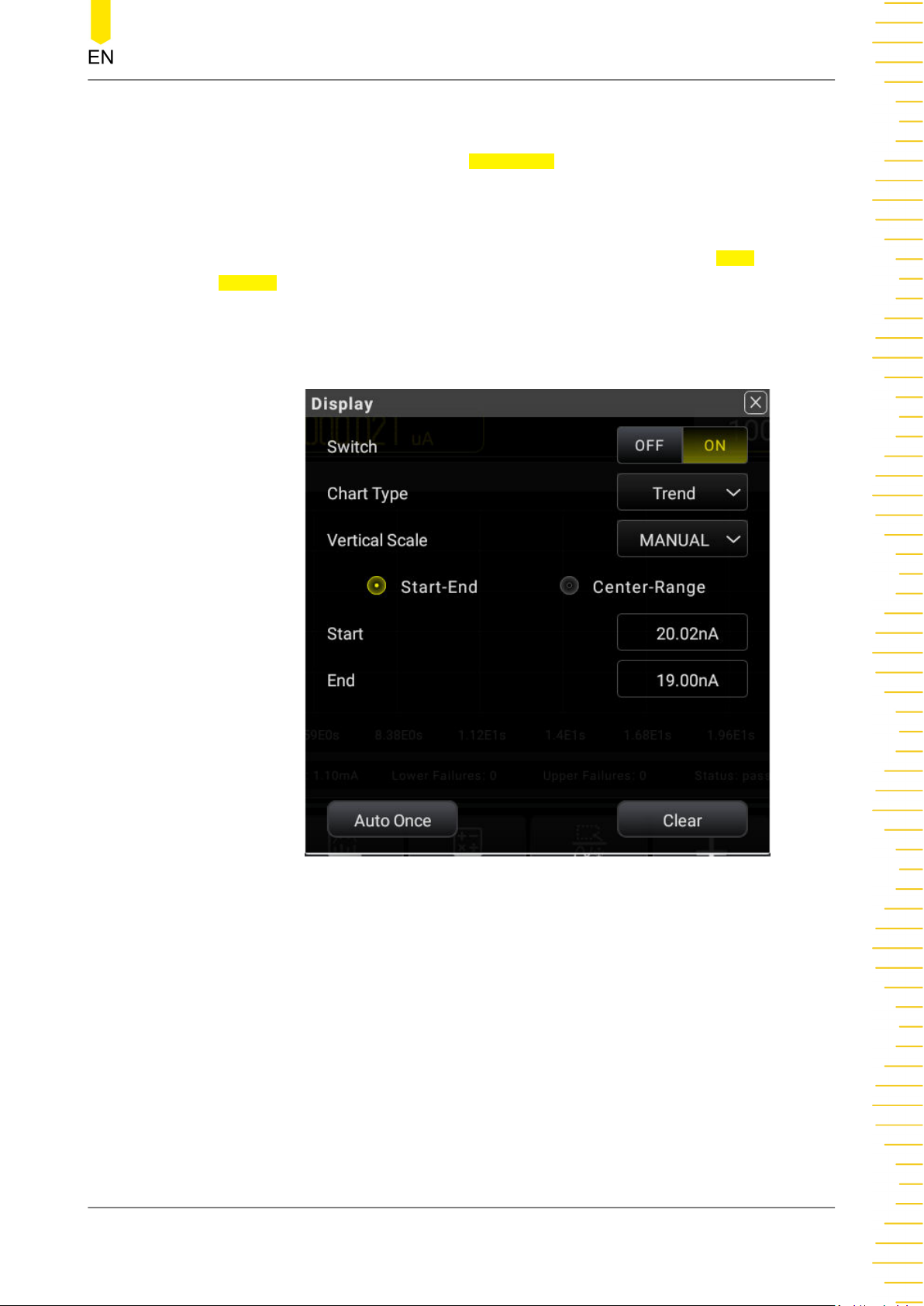
Front Panel Operation
2. Select the graph type
Click or tap the drop-down list of Chart Type to select "Trend". Then the following
interface is displayed.
3. Set the vertical scale
Vertical Scale: sets the vertical scale of the trend graph. It supports Auto and
Manual setting modes.
- Manual: You can set the vertical scale manually with two modes: Start-End and
Center-Span.
Figure 5.51 Manual Setting Menu
- Start: sets the start value of the horizontal scale.
- End: sets the end value of the vertical scale.
- Center: sets the middle value of the vertical scale.
- Range: sets the span of the vertical scale.
Copyright ©RIGOL TECHNOLOGIES CO., LTD. All rights reserved. DM858 Series User Guide
83
Page 96
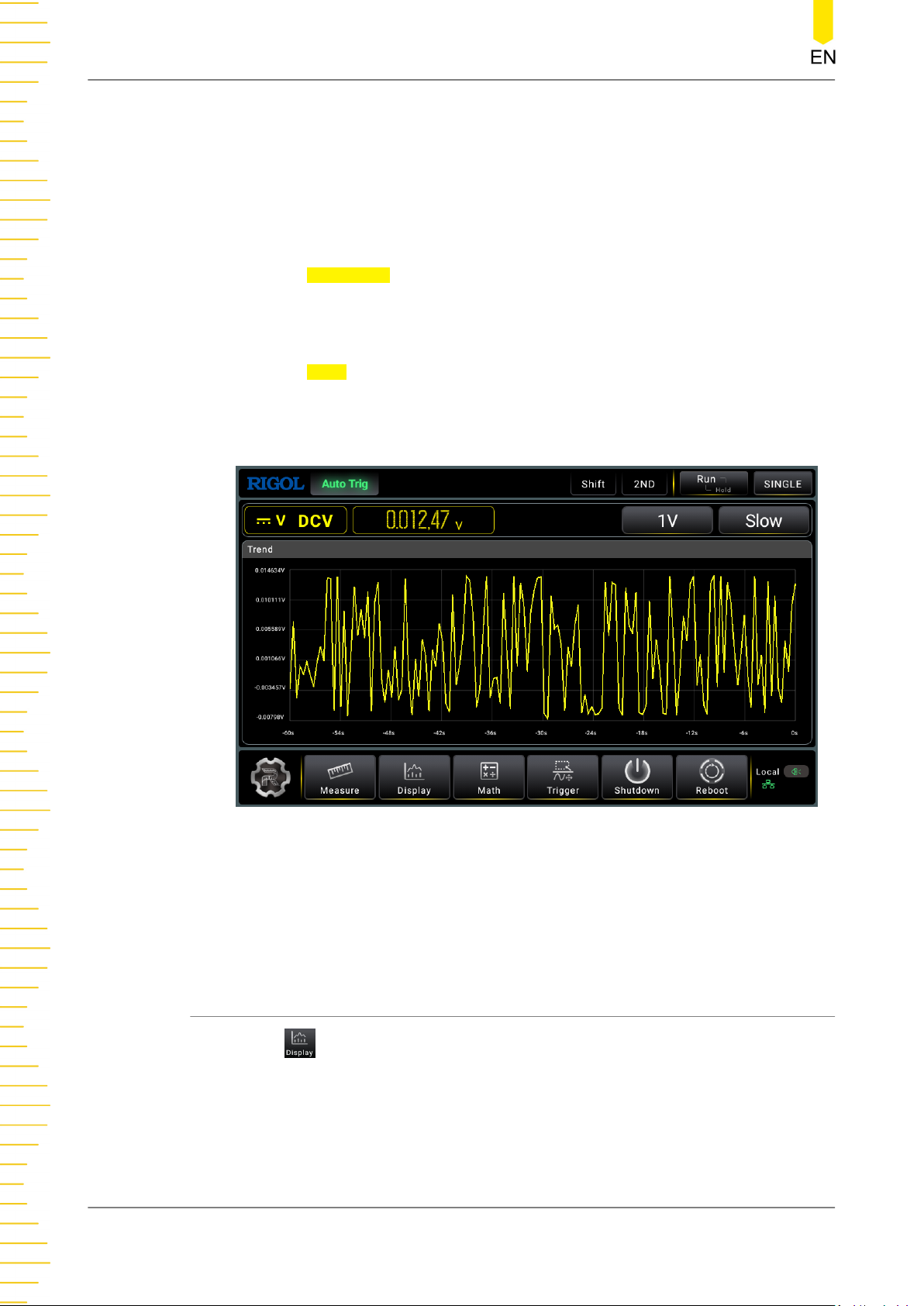
Front Panel Operation
- Auto: takes the current measurement range as the span of the vertical scale and
adjusts the span of the vertical scale automatically based on the range of the
measured data.
4. Auto Once
Click or tap Auto Once, the instrument auto adjusts the span of the vertical scale
based on the range of the measured data.
5. Clear
Click or tap Clear to clear the existing reading memory and the data in the trend
graph, and start to acquire new readings to make a new trend.
The following figure shows the trend display for the DCV measurement.
The measurement rate for Capacitance, Period, and Frequecny is fixed to be Slow.
In Slow and Medium speed, the Trend graph only displays the samples within 60 s; in
Fast speed, the Trend graph only displays samples within 10 s.
5.7.2 Histogram
Click or tap to enter the display interface.
DM858 Series User Guide
84
Figure 5.52 Trend Graph of DCV Measurement
Copyright ©RIGOL TECHNOLOGIES CO., LTD. All rights reserved.
Page 97
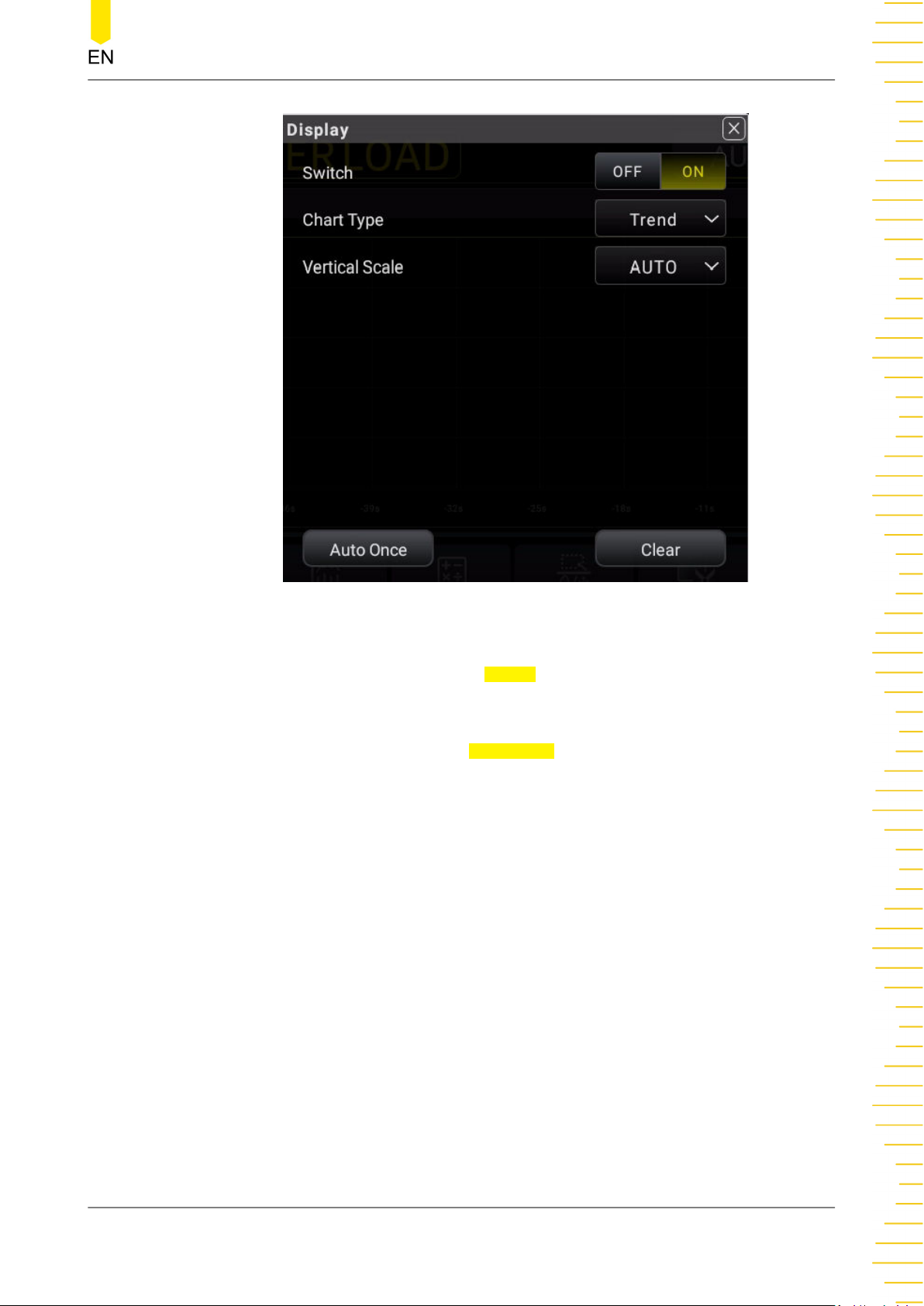
Front Panel Operation
Figure 5.53 Graph Display Interface
1. Click or tap the ON/OFF tab for the Switch menu to enable or disable the graph
display.
2. Click or tap the drop-down list of Chart Type to select "Histogram". Then the
following interface is displayed.
Copyright ©RIGOL TECHNOLOGIES CO., LTD. All rights reserved. DM858 Series User Guide
85
Page 98
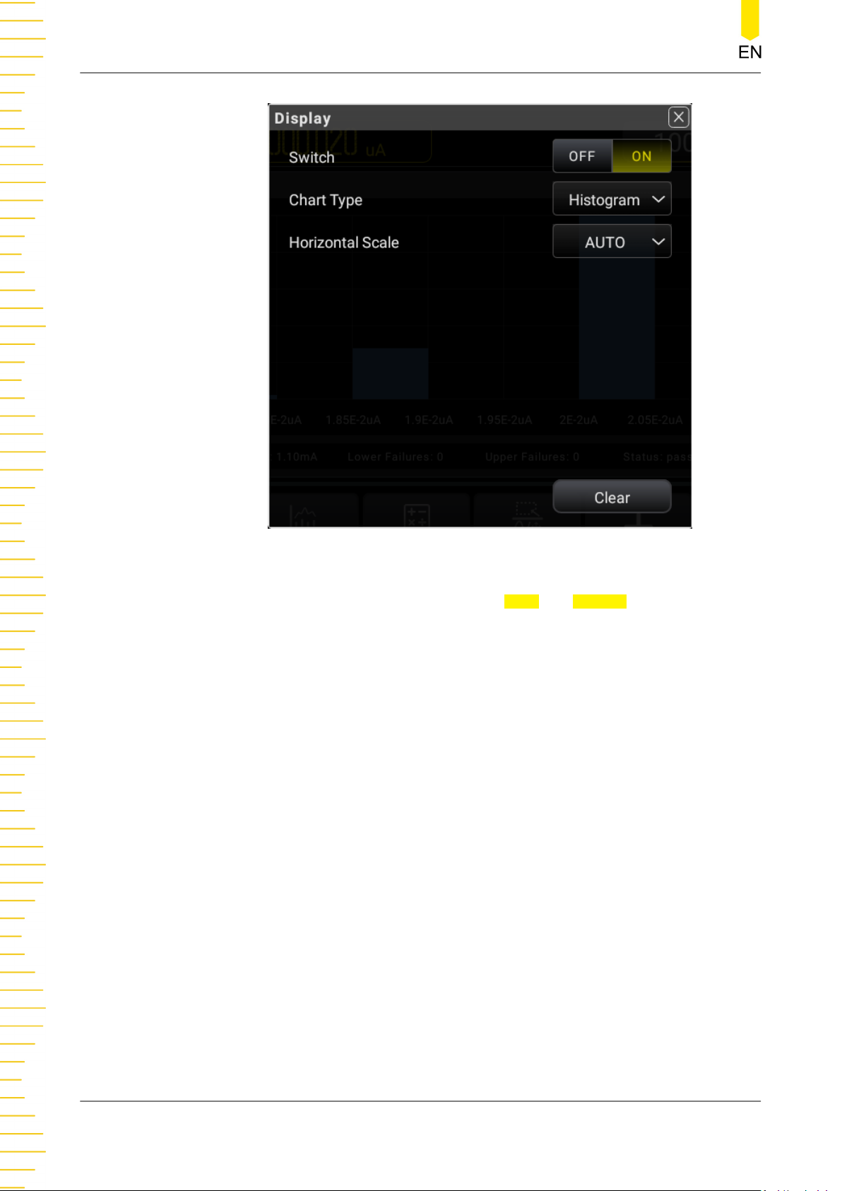
Front Panel Operation
Figure 5.54 Histogram Setting Interface
3. The X-axis setting of the histogram supports Auto and Manual.
- Auto: the number of bins is a fixed number 10. The outer bin is disabled. The
readouts outside of the upper and lower limits will not be displayed on the
histogram. Its upper and lower limits are automatically set based on the current
range.
- Manual: sets the parameters of the histogram display manually, including the
range type (start-end/center-range) displayed in the horizontal scale of the
histogram, the number of bins, whether enabling or disabling the outer bin.
DM858 Series User Guide
86
Copyright ©RIGOL TECHNOLOGIES CO., LTD. All rights reserved.
Page 99
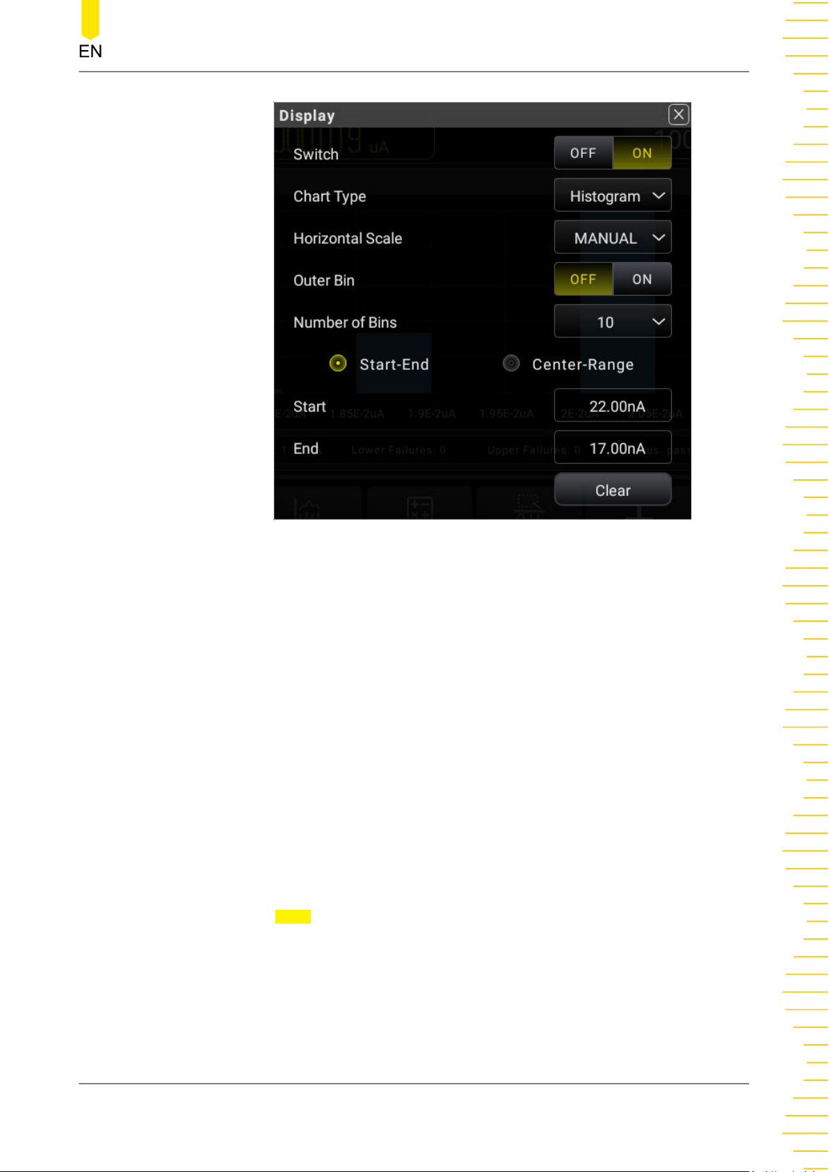
Front Panel Operation
Figure 5.55 Histogram Manual Setting
- Outer Bin: sets to enable or disable the display of the additional bins at both
left and right ends of the horizontal scale of the histogram, which can make
statistics on the data that are above or below the horizontal scale range.
- Number of Bins: sets the number of bins. The available settings are 10, 20,
40, 100, 200, and 400.
- End: sets the end value of the horizontal scale.
- Start: sets the start value of the horizontal scale.
- Center: sets the middle value of the horizontal scale.
- Range: sets the range value of the horizontal scale.
4. Click or tap Clear to clear the existing reading memory and the data in the trend
graph, and start to acquire new readings to make a new trend.
5. The following figure shows the histogram display for the DCV measurement.
Copyright ©RIGOL TECHNOLOGIES CO., LTD. All rights reserved. DM858 Series User Guide
87
Page 100
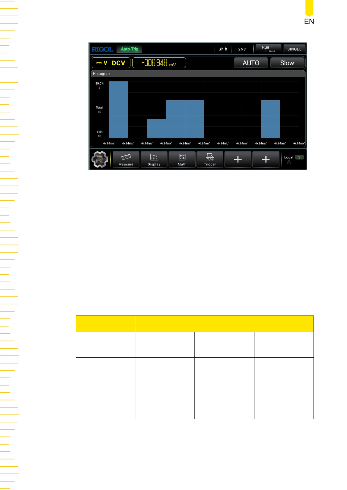
Front Panel Operation
Figure 5.56 Histogram of DCV Measurement
As shown in the figure above, data are grouped in bins represented by vertical
bars in the histogram display. The data are displayed on the left side of the
histogram. Read the data from left downward.
- 82.6%: indicates the percentage of samples in the largest bin.
- 419: indicates the number of samples in the largest bin.
- Total 507: indicates the total number of samples.
- #bin 10: indicates the total number of bins.
For different measurement modes, the max. number of samples supported by the
histogram is different. See the following table for details.
Table 5.21 Max. Number of Samples Displayed in the Histogram
Measurement Rate Max. Number of Samples
Capacitance
Measurement
Frequency/Period
Measurement
Other
Measurements
Slow 61 45 150
Medium N/A N/A 1050
Fast N/A N/A
The measurement rate for Capacitance, Period, and Frequency measurements is Slow.
DM858 Series User Guide
88
DM858: 1000
DM858E: 700
Copyright ©RIGOL TECHNOLOGIES CO., LTD. All rights reserved.
 Loading...