

Page 1

User’s Guide RIGOL
Publication number: UGC01106-1110
DM3000 Series Digital Multimeter
© 2007 RIGOL Technologies, Inc. All Rights Reserved
DM3061/2/4
DM3051/2/4
Page 2

Page 3

RIGOL
z © 2007 RIGOL Technologies, Inc. All Rights Reserved.
z RIGOL products are protected by patent law in and outside of P.R. China.
z Information in this publication replaces all previously corresponding material.
z RIGOL Technologies, Inc. reserves the right to modify or change part of or all
the specifications and pricing policies at company’s sole decision.
NOTE: RIGOL is registered trademark of RIGOL TECHNOLOGIES, INC.
© 2007 RIGOL Technologies, Inc.
User’s Guide for DM3000 Series
I
Page 4

RIGOL
Safety Notices
Review the following safety precautions carefully before operating the instrument
to avoid any personal injuries or damages to the instrument and any products
connected to it.
To avoid potential hazards use the instrument as specified by this user’s guide
only.
The instrument should be serviced by qualified personnel only.
To Avoid Fire or Personal Injury.
Use Proper Power Cord. Use the power cord designed for the instrument as
authorized in your country only.
Ground The Instrument. The instrument is grounded through the grounding
conductor of the power cord. To avoid electric shock the instrument grounding
conductor(s) must be grounded properly before making connections to the input
or output terminals of the instrument.
Observe All Terminal Ratings. To avoid fire or shock hazard, observe all
ratings and marks on the instrument. Follow the user’s guide for further ratings
information before making connections to the instrument.
Do Not Operate Without Covers. Do not operate the instrument with covers
or panels removed.
Use Proper Fuse. Use the fuse of the type, voltage and current ratings as
specified for the instrument.
Avoid Circuit or Wire Exposure. Do not touch exposed connections and
components when power is on.
Do Not Operate With Suspected Failures. If suspected damage occurs with
the instrument, have it inspected by qualified service personnel before further
operations.
Do Not Operate in Wet/Damp Conditions.
Do Not Operate in an Explosive atmosphere.
Keep Product Surfaces Clean and Dry.
II
© 2007 RIGOL Technologies, Inc.
User’s Guide for DM3000 Series
Page 5

RIGOL
The disturbance test of all the models meet the limit values of A in the
standard of EN 61326: 1997+A1+A2+A3, but can’t meet the limit
values of B.
WARNING
IEC Measurement Category II. The HI and LO input terminals may be connected
to mains in IEC Category II installations for line voltages up to 300 VAC. To avoid
the danger of electric shock, do not connect the inputs to mains for line voltages
above 300 VAC.
Protection Limits: To avoid instrument damage and the risk of electric shock, do
not exceed any of the Protection Limits defined in the following section.
IEC Measurement Category II Overvoltage Protection
To protect against the danger of electric shock, the RIGOL DM3000 series
Digital Multimeter provides overvoltage protection for line-voltage mains
connections meeting both of the following conditions: The HI and LO input
terminals are connected to the mains under Measurement Category II conditions,
defined below, and The mains are limited to a maximum line voltage of 300 VAC.
IEC Measurement Category II includes electrical devices connected to mains at
an outlet on a branch circuit.
Such devices include most small appliances, test equipment, and other devices
that plug into a branch outlet or socket. The DM3000 series Digital Multimeter
may be used to make measurements with the HI and LO inputs connected to
mains in such devices, or to the branch outlet itself (up to 300 VAC). However,
the DM3000 series Digital Multimeter may not be used with its HI and LO inputs
connected to mains in permanently installed electrical devices such as the main
circuit-breaker panel, sub-panel disconnect boxes, or permanently wired motors.
Such devices and circuits are subject to overvoltage that may exceed the
protection limits of the DM3000 series Digital Multimeter.
Note: Voltages above 300 VAC may be measured only in circuits that are isolated
from mains. However, transient overvoltage are also present on circuits that are
isolated from mains. The DM3000 series Digital Multimeter is designed to safely
withstand occasional transient overvoltage up to 2500 Vpk. Do not use this
equipment to measure circuits where transient overvoltage could exceed this
level.
© 2007 RIGOL Technologies, Inc.
User’s Guide for DM3000 Series
III
Page 6
RIGOL
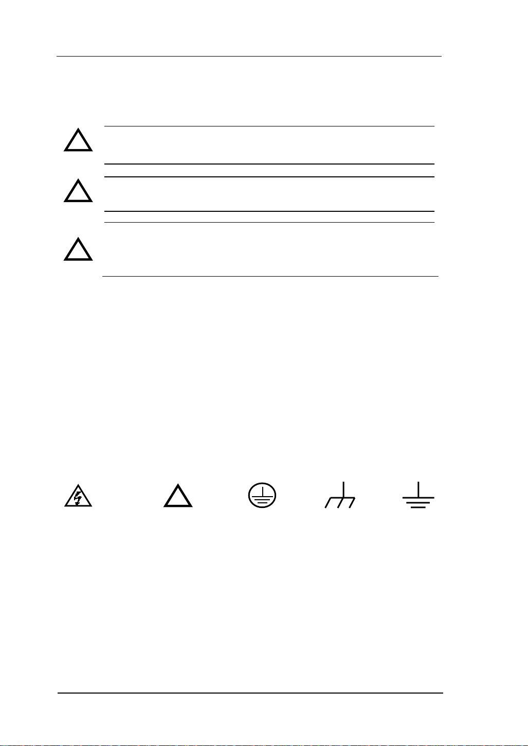
Safety Terms and Symbols
Terms in This Guide. These terms may appear in this guide:
WARNING: Warning statements identify conditions or practices that
!
could result in injury or loss of life.
CAUTION: Caution statements identify conditions or practices that
!
could result in damage to this product or other property.
CAT II (300V): IEC Measurement Category II. Inputs may be
connected to mains (up to 300 VAC) under Category II overvoltage
!
conditions.
Terms on the Product: These terms may appear on the product:
DANGER indicates an injury hazard may happen immediately.
WARNING indicates an injury hazard may not happen immediately.
CAUTION indicates that a potential damage to the instrument or other property
might occur.
Symbols on the Product: These symbols may appear on the Instrument:
Hazardous
Voltage
!
Refer to
Instructions
Protective
Earth
Terminal
Chassis
Ground
Earth
Ground
IV
© 2007 RIGOL Technologies, Inc.
User’s Guide for DM3000 Series
Page 7
RIGOL
General-Purpose Multimeter
The book covers the following description and six models DM3000 Series Digital
Multimeter:
DM3061, DM3062, DM3064;
DM3051, DM3052, DM3054.
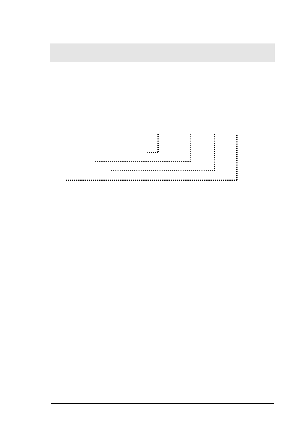
DM3000 Series Digital Multimeter naming rules:
Prefix desktop Digital Multimeter
Serial Number
6-6½, 5-5¾ digit
No.
1-Basic; 2-LAN/GPIB interface;
4-Inspection plate with the model and LAN/GPIB interface.
Application examples:
DM3061- 6½ DM3000 series, Basic type.
DM3062- 6½ DM3000 series, Basic type, equipped with LAN/GPIB module.
DM3064 - 6½ DM3000 series, Basic type, equipped with LAN/GPIB and
inspection module.
DM3051- 5¾ DM3000 series, Basic type.
DM3052- 5¾ DM3000 series, Basic type, equipped with LAN/GPIB module.
DM3054 - 5¾DM3000 series, Basic type, equipped with LAN/GPIB and
inspection module.
© 2007 RIGOL Technologies, Inc.
User’s Guide for DM3000 Series
DM
30
6 1
V
Page 8

RIGOL
RIGOL DM3000-Series Digital Multimeter is a equipment designed for
high-precision, multifunction, automation measurements. The series includes 6½
digits multimeter, with high-speed data acquisition, automatic measurements,
multiplexer, mathematical operations, and flexible user sensor configurations etc.
Interface includes RS-232, USB, LAN, GPIB for disk storage and print.
The DM3000 has a high-resolution monochrome LCD display system for simple
waveform display and recording. The concise and user-friendly layout of the front
panel has a keyboard, and back lighted functional buttons, embedded with
operating instructions makes the instrument more flexible, and capable. The
50kSa/s high data sampling rate allows to capture precision audio waveforms and
high speed data. It has 2Mbyte of internal memory depth while the external
memory depth is expandable as preferred. The AC voltage and current
measurement is true RMS. It supports virtual terminal display and control, and
remote network access.
With the performance and characteristics given below, you will understand how a
DM3000 can satisfy your measurement requirements.
z 50kSa/s data sampling rate can be used, such as the rapidly changing
high-precision audio waveform data. Meanwhile waveform can be displayed
on LCD Screen
z Resolving Index: > 6½ digits and 2,400,000 Count
z 24 measurement functions
DC voltage and current, AC voltage and current, two-wire and four-wire
resistance, capacitance, continuity test, diode test, frequency, cycle,
ratio measurements, sensor measurement,
and so on.
Upper limit and lower limit on threshold measurement
Arithmetic include: maximum, minimum, limit, average, dBm, dB
Data acquisition functions include : data records, inspection, automatic
measurement.
z True RMS AC voltage and current measurement
z 16-Channels inspection functional measurement and control software
(optional)
z DC voltage >10GΩ input impedance to achieve the range of 48V (±24V)
z 10 groups measuring set-up storage and unlimited setup through PC
interface
VI
© 2007 RIGOL Technologies, Inc.
User’s Guide for DM3000 Series
Page 9

RIGOL
z 256 x 64 pixel monochrome LCD
z I/O: RS-232, USB, LAN and GPIB
z Built-in USB Host to support USB disk and USB printer
z Simple, convenient, flexible control software: Ultralogger, Ultrasensor and
UltraDMM Supports for Microsoft® Windows 98/Me/2000/XP
Note: The chapter one, chapter two, chapter three will be described according to
6½ digits. For 5¾ digits, please refer to ‘’Chapter five: Characteristics for
DM306x’’.
© 2007 RIGOL Technologies, Inc.
User’s Guide for DM3000 Series
VII
Page 10

RIGOL
Content
Safety Notices ...........................................................................................II
General-Purpose Multimeter .......................................................................V
CHAPTER 1 QUICK START.....................................................................1-1
General Inspection.................................................................................. 1-2
Handle Adjustment ................................................................................. 1-3
The Front/Rear Panel and User Interface.................................................. 1-4
To Measure DC Voltage........................................................................... 1-6
To Measure AC Voltage ........................................................................... 1-8
To Measure DC Current......................................................................... 1-10
To Measure AC Current ......................................................................... 1-12
To Measure Resistance.......................................................................... 1-14
To Measure Capacitance........................................................................ 1-18
To Test Continuity ................................................................................ 1-20
To Check Diodes................................................................................... 1-22
To Measure Frequency and Period ......................................................... 1-24
To Measure Sensor ............................................................................... 1-28
To Choose Reading Resolution............................................................... 1-34
To Choose Data Digit Display................................................................. 1-35
To Choose Range Options ..................................................................... 1-36
To Control Trigger Options .................................................................... 1-38
CHAPTER 2 OPERATING YOUR MULTIMETER.......................................2-1
To Set up Measurement Parameters......................................................... 2-2
Math Functions..................................................................................... 2-12
To Set Up Triggering Parameter Function ............................................... 2-19
Store and Recall ................................................................................... 2-27
To Set Up the Utility.............................................................................. 2-32
High-Speed Data Log ............................................................................ 2-48
Multi-Route Scanning ............................................................................ 2-56
How to Use the Built-in Help System ...................................................... 2-64
CHAPTER 3 APPLICATION EXAMPLES ..................................................3-3
Example 1: Reading Statistic Functions..................................................... 3-3
Example 2: Elimination Leads Resistance Error.......................................... 3-5
Example 3: dBm Measurement ................................................................ 3-6
Example 4: dB Measurement ................................................................... 3-7
VIII
© 2007 RIGOL Technologies, Inc.
User’s Guide for DM3000 Series
Page 11

RIGOL
Example 5: Limit Test.............................................................................. 3-9
Example 6: Temperature Sensor ............................................................ 3-10
Example 7: Reading Hold ...................................................................... 3-15
CHAPTER 4 PROMPT MESSAGES& TROUBLESHOOTING...................... 4-1
Prompting Message................................................................................. 4-1
Troubleshooting...................................................................................... 4-3
CHAPTER 5 CHARACTERISTICS ...........................................................5-1
Characteristics for DM306x ...................................................................... 5-1
Characteristics for DM305x .................................................................... 5-11
CHAPTER 6 APPENDIX ......................................................................... 6-1
Appendix A: DM3000 Series Accessories ................................................... 6-1
Appendix B: Warranty (DM3000 Series Digital Multimeters)........................ 6-2
Appendix C: General Care and Cleaning.................................................... 6-3
Appendix D: Contact RIGOL..................................................................... 6-4
© 2007 RIGOL Technologies, Inc.
User’s Guide for DM3000 Series
IX
Page 12

Page 13

RIGOL
Chapter 1 Quick Start
This chapter covers the following topics:
General Inspection
Handle Adjustment
The Front Panel and User Interface
To Measure DC Voltage
To Measure AC Voltage
To Measure DC Current
To Measure AC Current
To Measure Resistance
To M ea su re Ca pa ci ta nc e
To Test Continuity
To Check Diodes
To Measure Frequency and Period
To Make an Sensor measurement
To Choose Digits resolving index
To Choose Data Digit Display
To Choose Range Options
To Control Trigger Options
© 2007 RIGOL Technologies, Inc.
User’s Guide for DM3000 Series
1-1
Page 14

RIGOL
General Inspection
Inspect a new DM3000 Digital Multimeter with the following steps:
1. Inspect the shipping container for damage.
Keep the damaged shipping container or cushioning material until the contents of the
shipment have been checked for completeness and the instrument has been checked
mechanically and electrically.
2. Check the accessories.
Accessories supplied with the instrument are listed in "Accessories" at Appendix B of
this guide.
If the contents are incomplete or damaged, please notify the RIGOL Sales
Representative.
3. Inspect the instrument.
In case of any damage, or defect, or failure, notify the RIGOL Sales Representative.
If the shipping container is damaged, or the protective material shows signs of stress,
notify the carrier as well as your RIGOL sales office. Keep the shipping materials for
the carrier’s inspection.
RIGOL offices will arrange reparation or replacement at RIGOL’s option without
waiting for claim settlement.
1-2
© 2007 RIGOL Technologies, Inc.
User’s Guide for DM3000 Series
Page 15
RIGOL
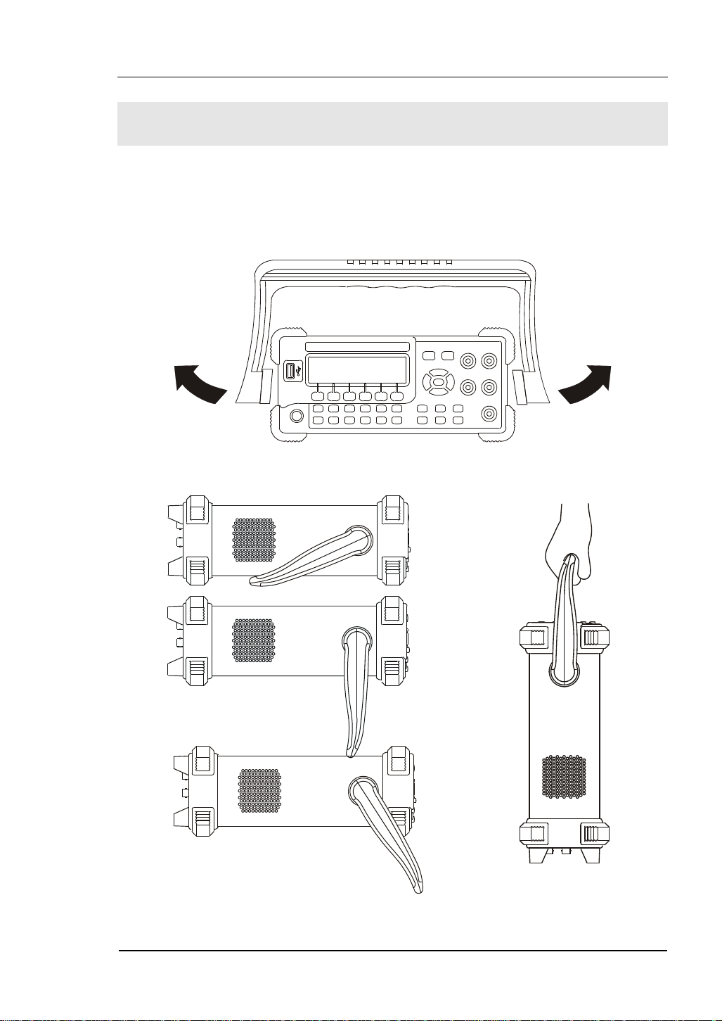
Handle Adjustment
To adjust the handle position of DM3000 Digital Multimeter, please grip the handle by
the sides and pull it outward. Then, rotate the handle to the desired position as
shown in
Figure 1- 1, Figure 1- 2.
Figure 1- 1
Figure 1- 2 Viewing Positions and Carrying Position
© 2007 RIGOL Technologies, Inc.
User’s Guide for DM3000 Series
1-3
Page 16
RIGOL
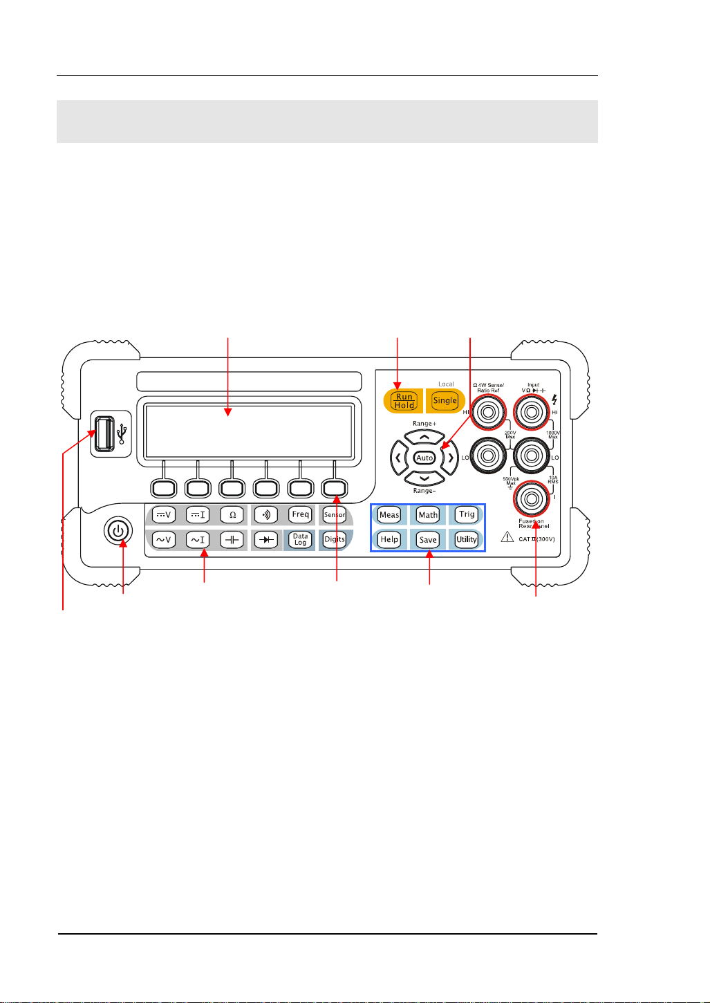
The Front/Rear Panel and User Interface
It is important to get familiar with the front panel of a new DM3000. This chapter
gives an introduction of the operation and functions of the Front Panel.
The front panel of the DM3000 is user friendly as shown below. It includes 4
Direction buttons and 12 Function keys, 6 Menu keys and 2 Control keys as shows
below:
LCD Display
Yel low Di strict :
Trigger Control Keys
Direction Keys
USB Host
1-4
On/Off
Purple District:
Measurement
Function Keys
Menu Operation
Keys
Blue Direction:
Function Selective
Keys
Figure 1- 3 The Front Panel
© 2007 RIGOL Technologies, Inc.
User’s Guide for DM3000 Series
Current Input Terminal
Page 17
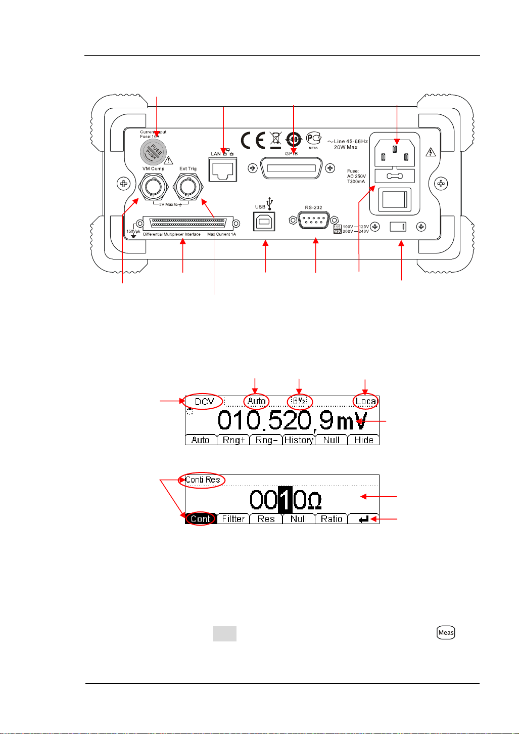
RIGOL
play
Current Input Fuse
10/100
Ethernet
GPIB
(IEEE--488)
Power Socket
VMC
Differential
Multiplexer Interface
Ext Trigger
USB Device RS--232
Power Fuse
AC Voltage
Selector
Figure 1- 4 The Rear Panel
Range
Digits
resolving
index
Local/Remote
Operation
Current
Measurement
Measurement
Data Display
Parameters
Name
Parameters
Dis
Operation
Menu
Figure 1- 5 The Interface Explanation
How the definitions express in this book:
In this manual, the regarding keys writing expression has the same log with the keys
on the front panel. It is noteworthy that the menu operates keys, marking with the
belt shadow. For example, Conti indicates the short circuit option in menu .
© 2007 RIGOL Technologies, Inc.
User’s Guide for DM3000 Series
1-5
Page 18
RIGOL
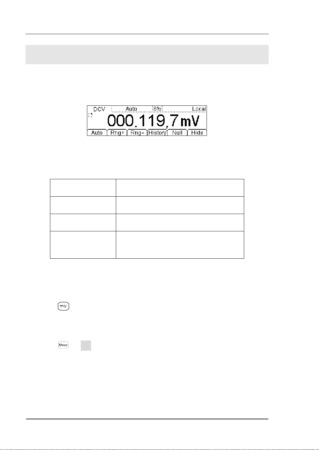
To Measure DC Voltage
The following shows the system connections and selection of measurement functions.
This practice provides a guide to get familiar with the DC Voltage measurement
technique.
Figure 1- 6 DC Voltage Measurement Data Interface
Table1- 1 DC Voltage Measurement Characteristics
Five Ranges 200mV, 2V, 20V, 200V, 1000V
Max Resolution 100nV
Input Protection 1000V on all ranges (HI Ter mi na l)
Configurable
Parameters
Range, DC impedance, Null value
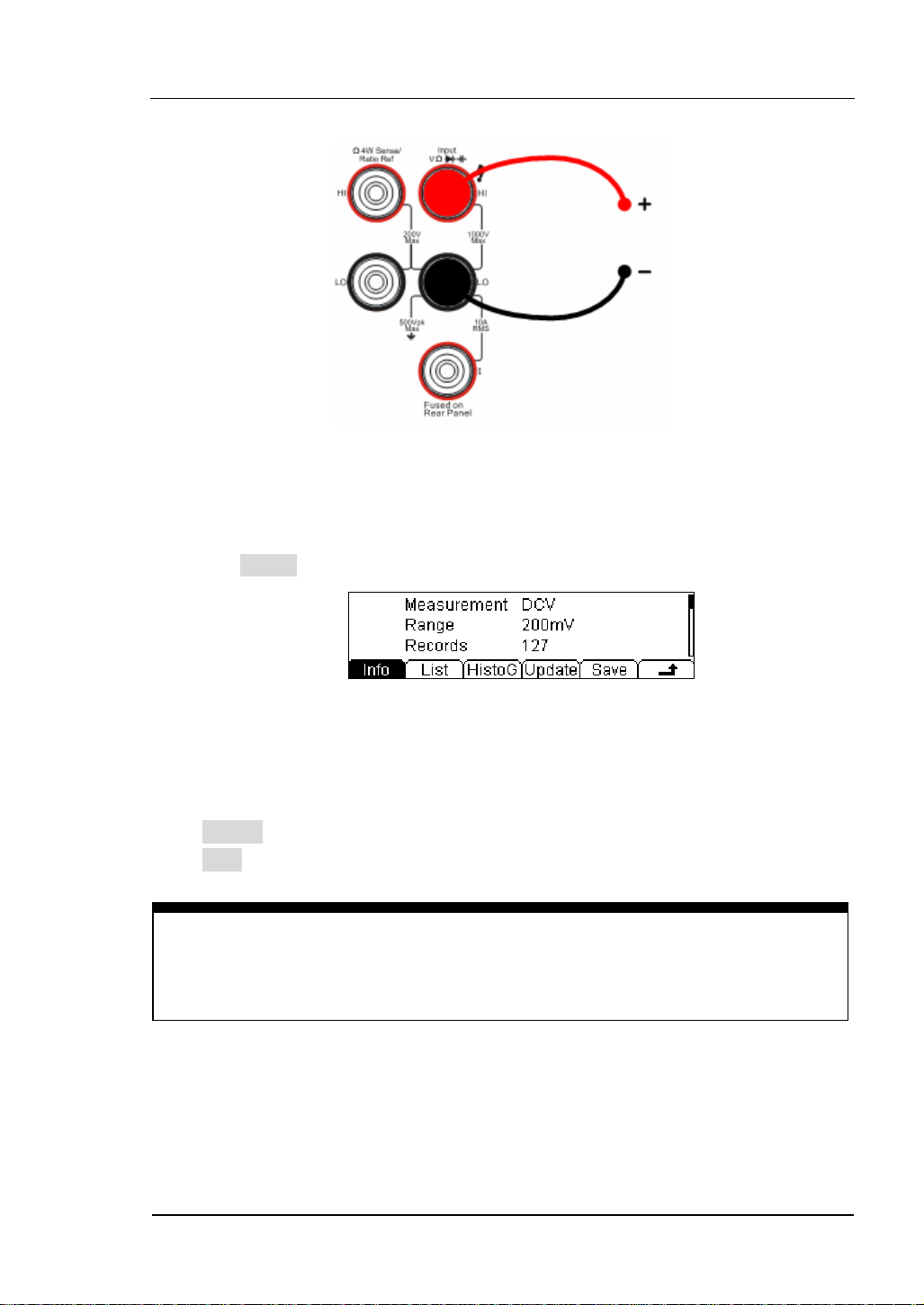
Basic measurement:
1. Connect the test leads as shown in
Figure 1- 7; red test lead to the HI Terminal,
black test lead to the LO Terminal.
2. Press
to select the DC Voltage measurement function.
3. Choose the appropriate measurement range.
4. Setup the DC impedance.
Press Æ Res, to setup the DC input impedance (Default value: 10MΩ).
5. Set the Null value.
Null computing will be an option operation, it could be setup in accordance with
user demand. If user does not implement Null computing, this parameter is not
required. (To know the specific setting methods of the Null value setting, please
refer to Chapter 2 “To Set Up Measurement Parameters”, Null computing)Lead
1-6
© 2007 RIGOL Technologies, Inc.
User’s Guide for DM3000 Series
Page 19
RIGOL
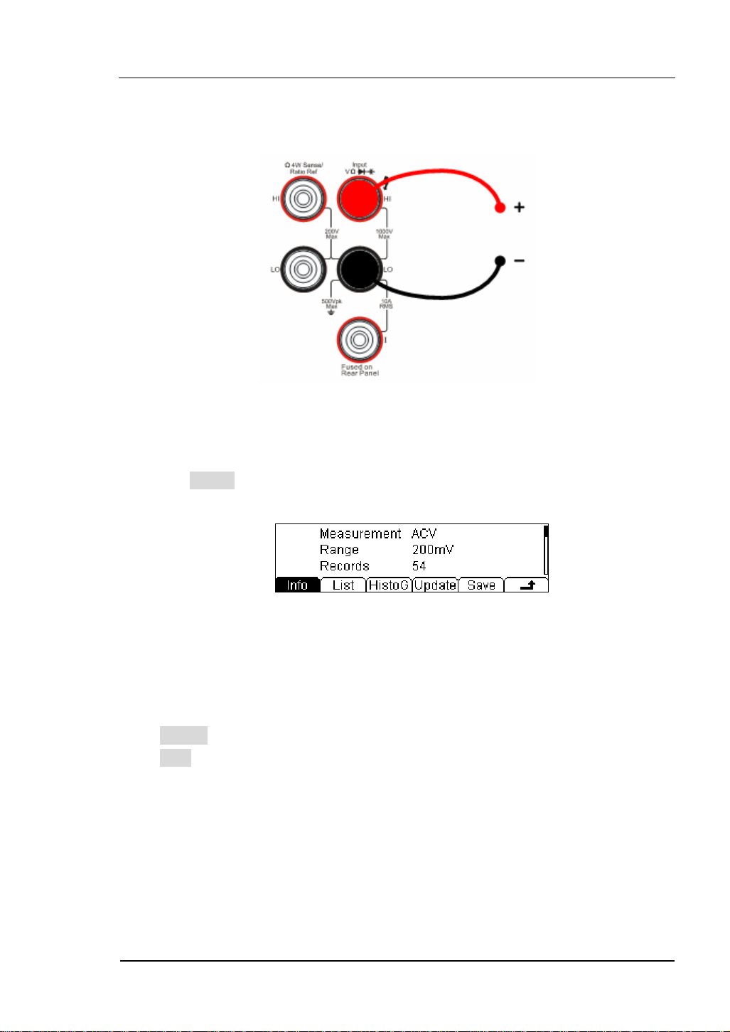
test leads into circuit and start to measure.
DC Voltage
Figure 1- 7 DC Voltage Measurement
6. Use history function.
Press History, the menu shows as below:
Figure 1- 8 The History Data
Use the history function to review or save the data that has acquired by the current
measurement function. The data can be display “Info” (information), “List” and
“HistoG” formats.
Press Update softkey to update the History data.
Press Save softkey to save data.
Note
Select Auto range if the measurement range is uncertain to get more accurate
measurement data.
© 2007 RIGOL Technologies, Inc.
User’s Guide for DM3000 Series
1-7
Page 20
RIGOL
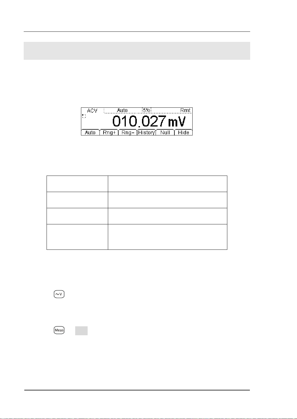
To Measure AC Voltage
The following shows the system connections and selection of measurement functions.
This practice provides a guide to get familiar with the AC Voltage measurement
technique. (The AC functions only support 5½ digits measurement.)
Figure 1- 9 AC Voltage Measurement Data Interface
Table1- 2 AC Voltage Measurement Characteristics
Five Ranges 200mV, 2V, 20V, 200V, 750V
Max Resolution 100nV
Input Protection 750VRMS on all ranges (HI Ter mi na l)
Configurable
Parameters
Range, DC impedance, Null value
Steps:
1. Connect test leads as shown in
Figure 1- 10; red test lead to the HI Terminal,
black test lead to the LO Terminal.
2. Press
to select the AC Voltage measurement function.
3. Choose the appropriate measurement range.
4. Setup the AC Filter.
Press Æ Filter, to setup the AC Filter Bandwidth (Default value: Mid).
5. Set the Null value.
Null computing will be an option operation, could be setup in accordance with
user demand. If user does not implement Null computing, this parameter is not
required, direct implementation of the next step.
1-8
© 2007 RIGOL Technologies, Inc.
User’s Guide for DM3000 Series
Page 21
RIGOL
(To know the specific setting methods of the Null value setting, please refer to
Chapter 2 “To Set Up Measurement Parameters”, Null computing)
6. Lead test leads into circuit and start to measure.
AC Voltage
Figure 1- 10 AC Voltage Measurement
7. Use history function.
Press History, the menu shows as below:
Figure 1- 11 The History Data
Use the history function to review or save the data that has acquired by the current
measurement function. The data can be display “Info” (information), “List” and
“HistoG” formats.
Press Update softkey to update the History data.
Press Save softkey to save data.
© 2007 RIGOL Technologies, Inc.
User’s Guide for DM3000 Series
1-9
Page 22
RIGOL
To Measure DC Current
The following shows the system connections and selection of measurement functions.
This practice provides a guide to get familiar with the DC Current measurement
technique.
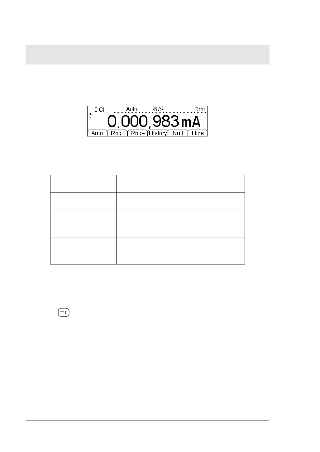
Figure 1- 12 DC Current Measurement Data Interface
Table1- 3 DC Current Measurement Characteristics
Five Ranges 2mA, 20mA, 200mA, 1A, 10A
Max Resolution 10nA
Input Protection
Configurable
Parameters
10A, 250V Current Input Fuse on rear
panel
Range, Null value
Steps:
1. Connect test leads as shown in
Figure 1- 13; red test lead to the HI Terminal,
black test lead to the LO terminal.
2. Press
to select the DC Current measurement function.
3. Choose the appropriate measurement range.
4. Set the Null value.
Null computing will be an option operation, could be setup in accordance with user
demand. If user does not implement Null computing, this parameter is not required,
direct implementation of the next step.
(To know the specific setting methods of the Null value setting, please refer to
Chapter 2 “To Set Up Measurement Parameters”, Null computing)
5. Lead test leads into circuit, start to measure.
1-10
© 2007 RIGOL Technologies, Inc.
User’s Guide for DM3000 Series
Page 23
RIGOL
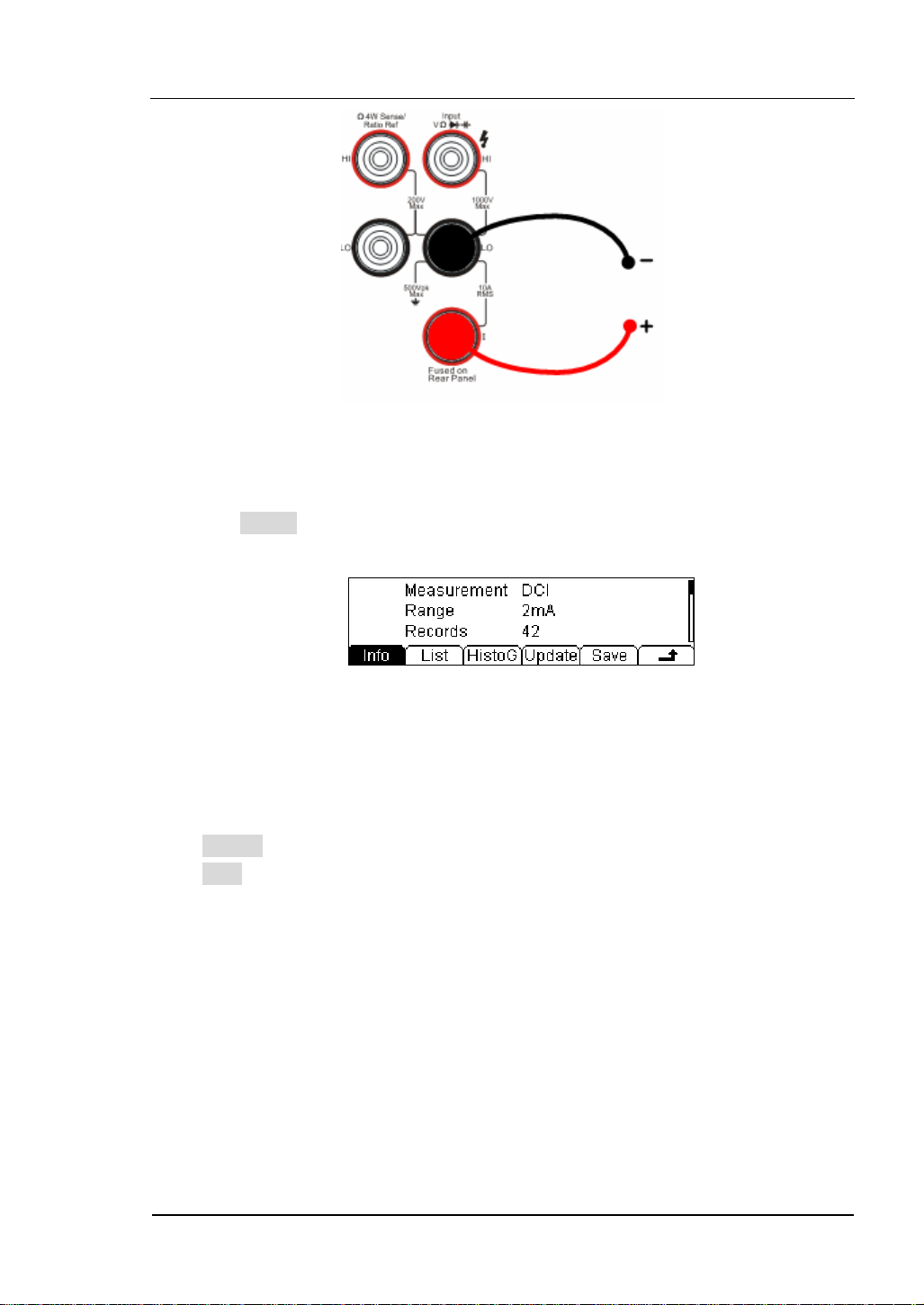
DC Current
Figure 1- 13 DC Current Measurement
6. Use history function.
Press History, the menu shows as below:
Figure 1- 14 The History Data
Use the history function to review or save the data that has acquired by the current
measurement function. The data can be display “Info” (information), “List” and
“HistoG” formats.
Press Update softkey to update the History data.
Press Save softkey to save data.
© 2007 RIGOL Technologies, Inc.
User’s Guide for DM3000 Series
1-11
Page 24
RIGOL
To Measure AC Current
The following shows the system connections and selection of measurement functions.
The practice provides as guide to be familiar with the AC Current measurement
technique. (The AC functions only support 5½ digits measurement.)
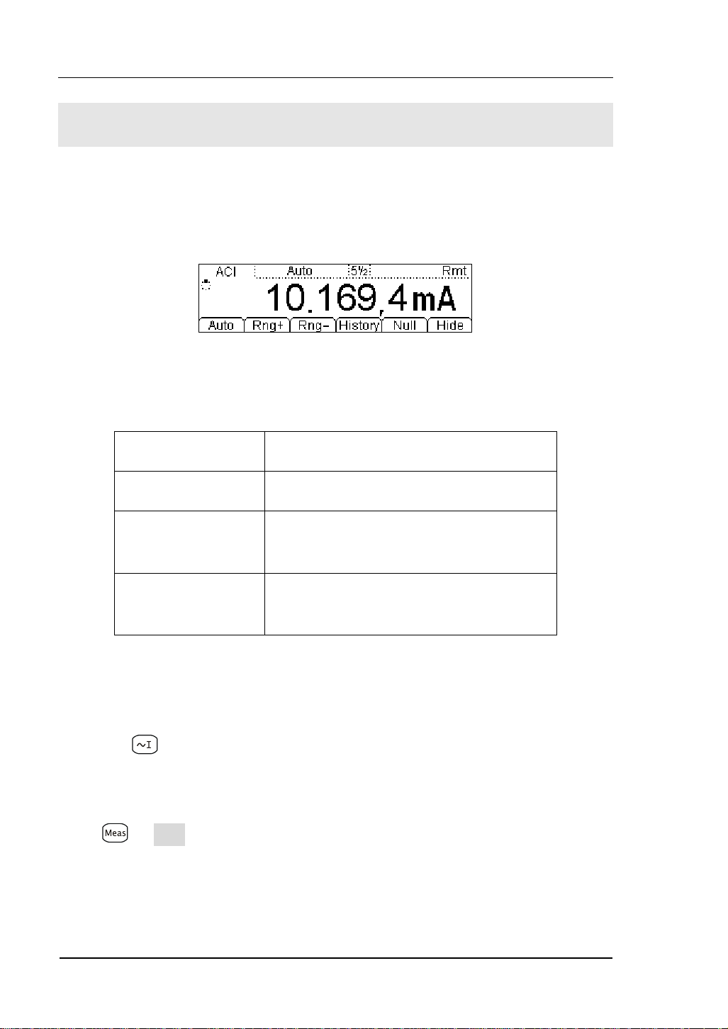
Figure 1- 15 AC Current Measurement Data Interface
Table1- 4 AC Current Measurement Characteristics
Five Ranges 20mA, 200mA, 1A, 10A
Max Resolution 100nA
Input Protection
Configurable
Parameters
10A, 250V Current Input Fuse on rear
panel
Range, AC Filter, Null value
Steps:
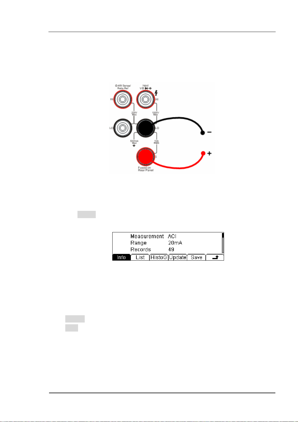
1. Connect test leads as shown in
Figure 1- 16; red test lead to the HI Terminal,
black test lead to LO Terminal.
2. Press
to select the AC Current measurement function.
3. Choose the appropriate measurement range.
4. Setup the AC Filter.
Press Æ Filter, to setup the AC Filter Bandwidth (Default value: “Mid” (Middle)).
5. Set the Null setting value.
Null computing will be an option operation, could be setup in accordance with
user
1-12
© 2007 RIGOL Technologies, Inc.
User’s Guide for DM3000 Series
Page 25
RIGOL
demand. If user does not implement Null computing, this parameter is not
required, direct implementation of the next step.
(To know the specific setting methods of the Null value setting, please refer to
Chapter 2 “To Set Up Measurement Parameters”, Null computing)
6. Lead test leads into circuit and start to measure.
AC Current
Figure 1- 16 AC Current Measurement
7. Use history function.
Press History, the menu shows as below:
Figure 1- 17 The History Data
Use the history function to review or save the data that has acquired by the current
measurement function. The data can be display “Info” (information), “List” and
“HistoG” formats.
Press Update softkey to update the History data.
Press Save softkey to save data.
© 2007 RIGOL Technologies, Inc.
User’s Guide for DM3000 Series
1-13
Page 26
RIGOL
To Measure Resistance
The following shows the system connections and selection of measurement functions.
The practice provides a guide get familiar with the Resistance measurement
technique. Resistance measurement methods include 2-Wire Resistance
Measurement and 4-Wire Resistance Measurement, and will explain
separately.
2-Wire Resistance Measurement
Figure 1- 18 2-Wire Resistance Measurement Interface
Table1- 5 Resistance Measurement Characteristics
Seven Ranges 200Ω, 2kΩ, 20kΩ, 200kΩ, 1MΩ, 10MΩ, 100MΩ
Max Resolution 100uΩ
Open-circuit
Voltage
Input Protection 1000V on all ranges (HI Ter mi na l)
Configurable
Parameters
Steps:
1. Connect test leads as shown in
black test lead to the LO Terminal.
2. Press
3. Choose the appropriate measurement range.
4. Set the Null value
to select the 2-Wire Resistance Measurement.
<7V
Range, Null value
Figure 1- 19; red test lead to the HI Terminal,
1-14
© 2007 RIGOL Technologies, Inc.
User’s Guide for DM3000 Series
Page 27
RIGOL
Null computing will be an option operation, could be setup in accordance with user
demand. If user does not implement Null computing, this parameter is not
required, direct implementation of the next step.
(To know the specific setting methods of the Null value setting, please refer to
Chapter 2 “To Set Up Measurement Parameters”, Null computing)
5. Lead test leads into circuit and start to measure.
Resistance
Figure 1- 19 2-Wire Resistance Measurement
6. Use history function.
Press History, the menu shows as below:
Figure 1- 20 The History Data
Use the history function to review or save the data that has acquired by the current
measurement function. The data can be display “Info” (information), “List” and
“HistoG” formats.
Press Update softkey to update the History data.
Press Save softkey to save data.
NOTE
When measuring small value resistance, Null operation will be recommended, the
test wire impedance error could be eliminated.
© 2007 RIGOL Technologies, Inc.
User’s Guide for DM3000 Series
1-15
Page 28
RIGOL
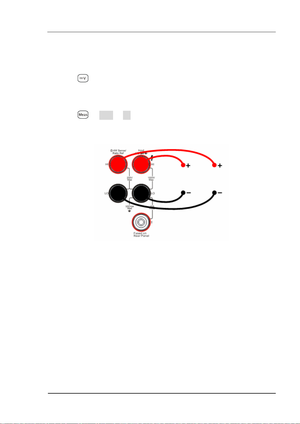
4-Wire Resistance Measurement
Figure 1- 21
Table1- 6 Resistance Measurement Characteristics
Seven Ranges 200Ω, 2kΩ, 20kΩ, 200kΩ, 1MΩ, 10MΩ, 100MΩ
Max Resolution 100uΩ
Open-circuit
Voltage
Import Protection
<7V
(1). 200V
PK
(2). 1000V on all ranges (HI
Terminal)
(3). 200V on all ranges (HI Sense, LO Sense)
Configurable
Parameters
Range, Null value
Steps:
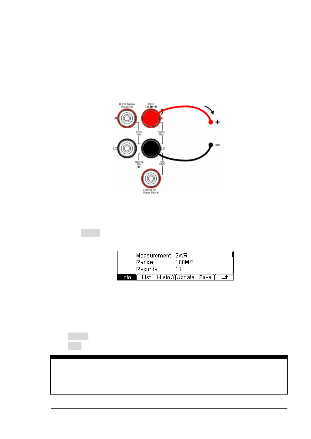
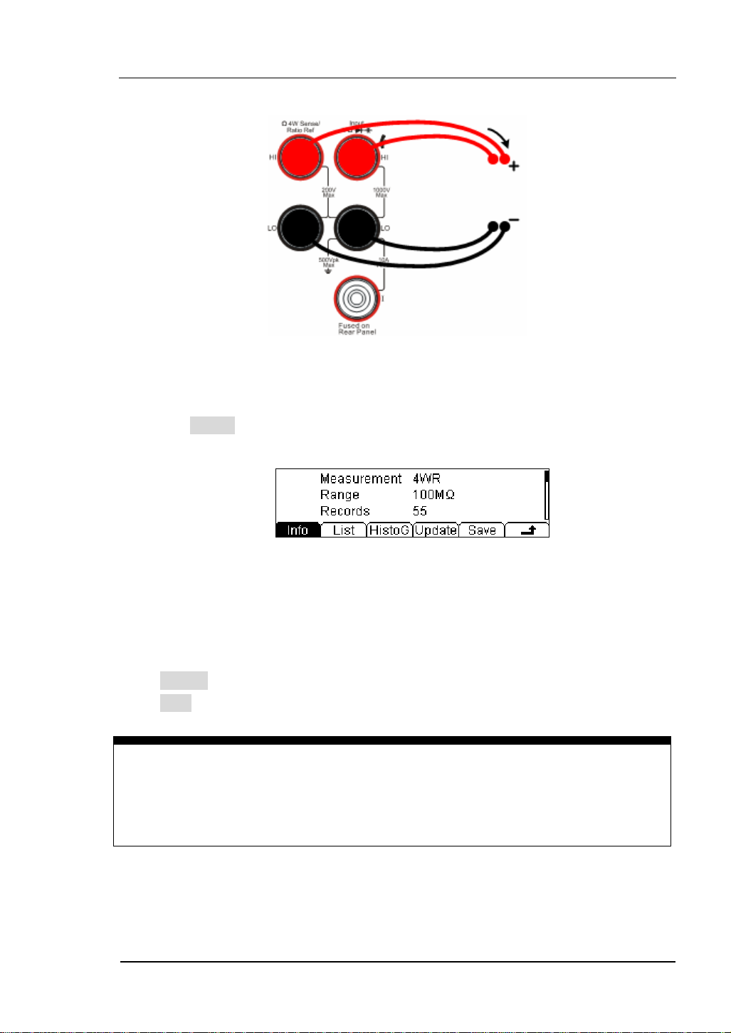
1. Connect test leads as show in
Figure 1- 22; red test lead to the HI Terminal,
black test lead to the LO Terminal.
2. Press
twice to select the 4-Wire Resistance Measurement.
3. Choose the appropriate measurement range.
4. Set the Null setting value.
Null computing will be an optional operation, it could be setup in accordance
with users’ demand. If user does not implement Null computing, this parameter
is not required, direct implementation of the next step.
(To know the specific setting methods of the Null value setting, please refer to
Chapter 2 “To Set Up Measurement Parameters”, Null computing)
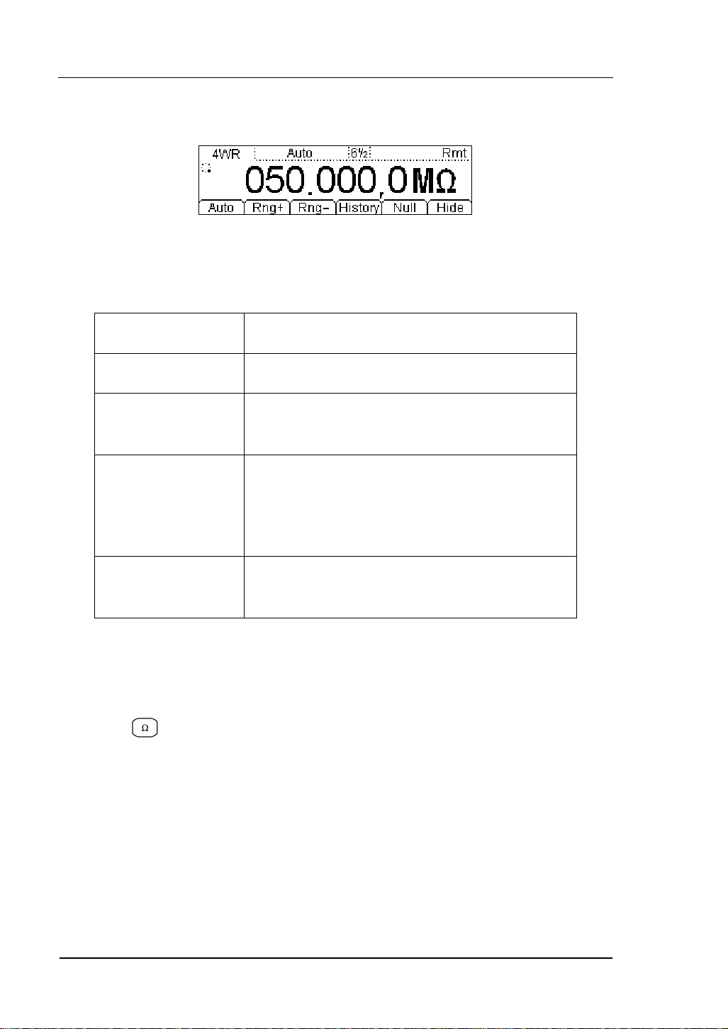
5. Lead test leads into circuit, start to measure.
1-16
© 2007 RIGOL Technologies, Inc.
User’s Guide for DM3000 Series
Page 29
RIGOL
4-Wire Sense HI
Resistance
4-Wire Sense LO
Figure 1- 22 4-Wire Resistance Measurement
6. Use history function.
Press History, the menu shows as below:
Figure 1- 23 The History Data
Use the history function to review or save the data that has acquired by the current
measurement function. The data can be display “Info” (information), “List” and
“HistoG” formats.
Press Update softkey to update the History data.
Press Save softkey to save data.
NOTE
When measuring resistances,
measurement
.
avoid contacting both ends of the resistor for accurate
© 2007 RIGOL Technologies, Inc.
User’s Guide for DM3000 Series
1-17
Page 30
RIGOL
To Measure Capacitance
The following shows the system connections and selection of measurement functions.
The practice provides a guide to get familiar with the Capacitance measurement
technique.
Figure 1- 24 Capacitance Measurement Data Interface
Table1- 7 Capacitance Measurement Characteristics
Six Ranges 2nF, 20nF, 200nF, 2uF, 20uF, 200uF
Max Resolution 0.1pF
Input Protection 1000V on all ranges (HI Ter mi na l)
Configurable
Parameters
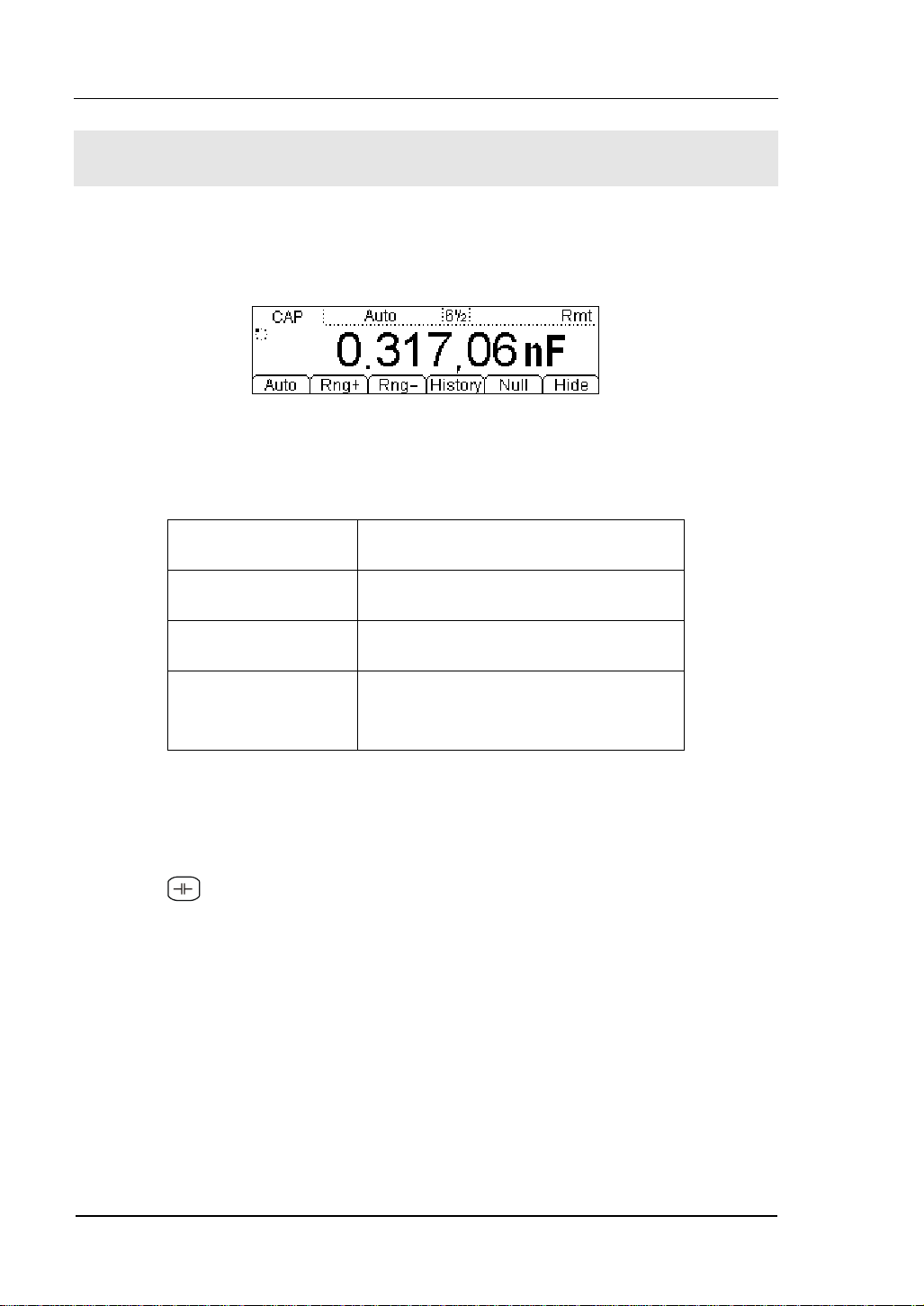
Basic measurement:
1. Connect test leads as shown in
black test lead to the LO Terminal.
2. Press
3. Choose the appropriate measurement range.
4. Set the Null value.
Null computing will be an optional operation, could be setup in accordance with
userdemand. If user does not implement Null computing, this parameter is not
required, direct implementation of the next step.
(To know the specific setting methods of the Null value setting, please refer to
Chapter 2 “To Set Up Measurement Parameters”, Null computing)
5. Lead test leads into circuit, start to measure.
to select the Capacitance measurement function.
Range, Null value
Figure 1- 25; red test lead to the HI Terminal,
1-18
© 2007 RIGOL Technologies, Inc.
User’s Guide for DM3000 Series
Page 31

RIGOL
Capacitance
Figure 1- 25 Capacitance Measurement
6. Use history function.
Press History, the menu shows as below:
Figure 1- 26 The History Data
Use the history function to review or save the data that has acquired by the current
measurement function. The data can be display “Info” (information), “List” and
“HistoG” formats.
Press Update softkey to update the History data.
Press Save softkey to save data.
NOTE
Before measuring the electrolytic capacitance, you should make the two legs of the
electrolytic capacitance short circuit and let it be discharged, and then you can
measure it.
© 2007 RIGOL Technologies, Inc.
User’s Guide for DM3000 Series
1-19
Page 32

RIGOL
To Test Continuity
The following shows the system connections and the selection of measurement
functions. The practice provides a guide to get familiar with the Continuity
measurement technique.
Figure 1- 27 Continuity Measurement Data Interface
Table1- 8 Continuity Measurement Characteristics
Tests Current 1mA
Max Resolution Range fixed at 2KΩ
Open-circuit Voltage <7V
Input Protection 1000V (HI Ter mi na l)
Configurable
Parameters
0≤R
≤Short-circuit impedance
testing
(0Ω≤Short-circuit impedance≤2kΩ)
Steps:
1. Connect test leads as
Figure 1- 28 shown. Red test lead connects the HI
Terminal, Black test lead connects the LO Terminal.
2. Press
to select the Continuity Measurement.
3. Setup the Short-circuit resistance.
Press Set button to set up the Short-circuit Impedance.
The default value is 10Ω. User may carry on the Continuity measurement
directly without modification.
4. Lead test leads into circuit, start to measure.
1-20
© 2007 RIGOL Technologies, Inc.
User’s Guide for DM3000 Series
Page 33

RIGOL
I
Open or Closed Circuit
Figure 1- 28 Continuity Measurement
© 2007 RIGOL Technologies, Inc.
User’s Guide for DM3000 Series
1-21
Page 34

RIGOL
To Check Diodes
The following shows the system connections and selection of measurement functions.
The practice provides a guide to get familiar with the Check Diodes technique.
Figure 1- 29 Check Diodes Interface
Table1- 9 Check Diodes Characteristics
Tests Current 1mA
Max Resolution Range fixed at 2VDC
Open-circuit Voltage <7V
Input Protection 1000V (HI Ter mi na l)
Configurable
Parameters
0.1V≤V
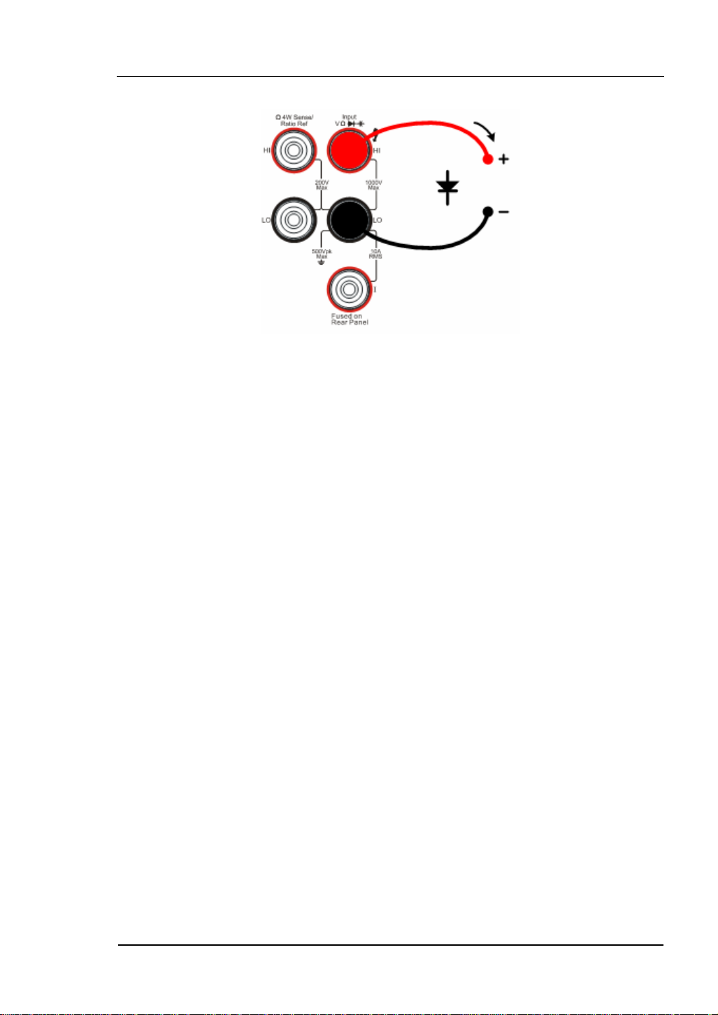
Steps:
1. Connect test leads as shown in
black test lead to the LO Terminal.
2. Press
to select the Check Diodes.
1-22
User’s Guide for DM3000 Series
measured
≤2V
Figure 1- 30, red test lead to the HI Terminal,
© 2007 RIGOL Technologies, Inc.
Page 35
RIGOL
3. Lead test leads into circuit and start to check.
I
Forward Bias
Figure 1- 30 Check Diodes
© 2007 RIGOL Technologies, Inc.
User’s Guide for DM3000 Series
1-23
Page 36

RIGOL
To Measure Frequency and Period
The following shows the system connections and selection of measurement functions.
The practice provides a guide to get familiar with the Frequency and Period
Measurement technique.
Frequency Test
Figure 1- 31 Frequency Measurement Data Interface
Table1- 10 Frequency Test Characteristics
Ranges 200mV, 2V, 20V, 200V, 750V
Measurement Range 3Hz~300kHz
Input Signal Range 100mVAC ~ 750VAC
Input Protection 750VRMS on all ranges (HI Ter mi na l)
Configurable Parameters Null value
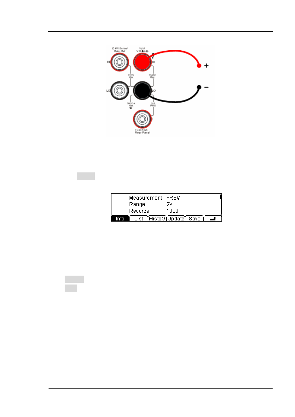
Basic measurement:
1. Connect test leads as
Terminal, Black test lead connects the LO Terminal.
2. Press
3. Set the Null value.
Null computing will be an option operation, could be setup in accordance with
user demand. If user does not implement Null computing, this parameter is not
required, direct implementation of the next step.
(To know the specific setting methods of the Null value setting, please refer to
Chapter 2 “To Set Up Measurement Parameters”, Null computing)
to select the Frequency Test.
Figure 1- 32 shown. Red test lead connects the HI
1-24
© 2007 RIGOL Technologies, Inc.
User’s Guide for DM3000 Series
Page 37
RIGOL
4. Lead test leads into circuit and start to check.
AC Signal
Figure 1- 32 Frequency Test
5. Use history function..
Press History, the menu shows as below:
Figure 1- 33 The History Data
Use the history function to review or save the data that has acquired by the current
measurement function. The data can be display “Info” (information), “List” and
“HistoG” formats.
Press Update softkey to update the History data.
Press Save softkey to save data.
© 2007 RIGOL Technologies, Inc.
User’s Guide for DM3000 Series
1-25
Page 38

RIGOL
Period Test
Figure 1- 34 Period Measurement Data Interface
Table1- 11 Period Test Characteristics
Range 200mV, 2V, 20V, 200V, 750V
Measurement Range 0.33s ~ 3.3us
Input Signal Range 100mVAC~750VAC
Import Protection 750VRMS on all ranges (HI Ter mi na l)
Configurable Parameters Null value
Steps:
1. Connect test leads as
Figure 1- 35 shown. Red test lead connects the HI
Terminal, Black test lead connects the LO Terminal.
2. Press
twice to select the Period Test.
3. Set the Null value.
Null computing will be an optional operation, could be setup in accordance with
users’ demand. If user does not implement Null computing, this parameter is
not required, direct implementation of the next step.
(To know the specific setting methods of the Null value setting, please refer to
Chapter 2 “To Set Up Measurement Parameters”, Null computing)
1-26
User’s Guide for DM3000 Series
© 2007 RIGOL Technologies, Inc.
Page 39

RIGOL
4. Lead test leads into circuit, start to check.
AC Signal
Figure 1- 35 Period Test
5. Use history function.
Press History, the menu shows as below:
Figure 1- 36 The History Data
Use the history function to review or save the data that has acquired by the current
measurement function. The data can be display “Info” (information), “List” and
“HistoG” formats.
Press Update softkey to update the History data.
Press Save softkey to save data.
© 2007 RIGOL Technologies, Inc.
User’s Guide for DM3000 Series
1-27
Page 40

RIGOL
To Measure Sensor
The DM3000 converts the sensor physical properties into electrical voltage,
resistance, current for measurement. So it needs the sensor name, sensor type,
sensor physical unit, sensor reference data, and arithmetic.
Figure 1- 37
Table1- 12 Sensor Building Options
New Newly built sensor reference data file
Edit Edit a sensor reference data file
Load Load a sensor reference data file
Display Set display mode
Steps:
1. Connect test leads as shown in
Figure 1- 54, Figure 1- 55, red test leads to the
HI Terminal, black test leads to the LO Terminal.
2. Press
to select the Sensor function.
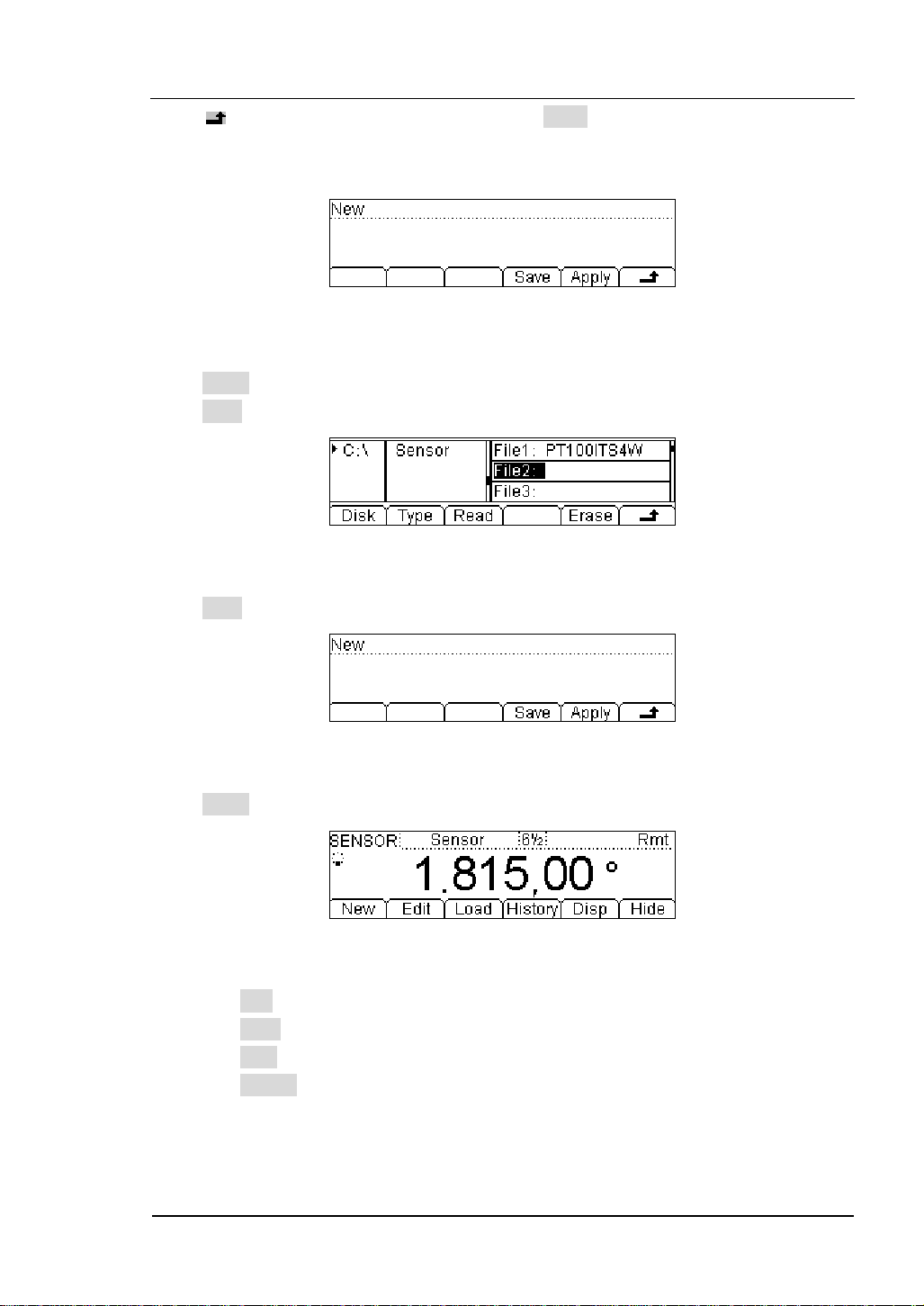
3. Press New, the display shows:
Figure 1- 38
(1). In New function interface, press Prpty to edit the sensor Name, sensor Type and
physical characteristics of the sensor.
1-28
© 2007 RIGOL Technologies, Inc.
User’s Guide for DM3000 Series
Page 41

RIGOL
Figure 1- 39
Press Name button, create a name for the sensor reference name.
Figure 1- 40
Press Done button to finish the input work.
Press Type button, to select the sensor type, include: DC voltage,DC current,2-wire,
4-wire resistance and frequency.
Figure 1- 41
Press
button back to the higher level menu.
Press Unit button, to select the physical unit, include: , ℃ Pa, %, °, and F.
Figure 1- 42
Press
button back to the higher level menu.
In New interface, press Define button to build the reference table.
Figure 1- 43
© 2007 RIGOL Technologies, Inc.
User’s Guide for DM3000 Series
1-29
Page 42

RIGOL
Press Add button, to input the Measured and Corresponding value to the reference
value data.
Figure 1- 44
Figure 1- 45
Figure 1- 46
Press SEG button, you are allowed to segment the reference value with different
arithmetic.
Press Arith button select the algorithms to Linear or Curvilinear.
Figure 1- 47
Figure 1- 48
1-30
© 2007 RIGOL Technologies, Inc.
User’s Guide for DM3000 Series
Page 43
RIGOL
Press return to New interface then press Done button, you have finished the
input work, then you can use this sensor reference immediately, or you can save it
into the built-in storage space or your U-disk for future work.
Figure 1- 49
Press Apply button, to use this reference value file.
Press Save to save the file.
Figure 1- 50
Press Save button, to finish the save operation.
Figure 1- 51
Press Apply button, to start the sensor measurement.
Figure 1- 52
(2). Press Edit button, to edit the saved sensor reference values.
(3). Press Load button, to load the saved sensor reference file.
(4). Press Disp button, to choose the value to be shown on the display interface.
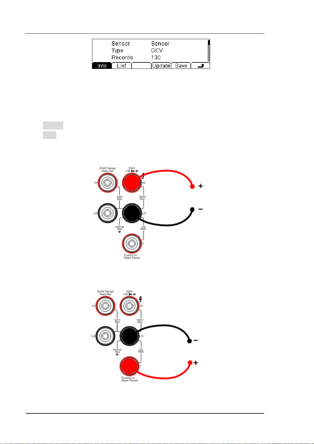
(5). Press History, enter the menu shown below:
© 2007 RIGOL Technologies, Inc.
User’s Guide for DM3000 Series
1-31
Page 44
RIGOL
Figure 1- 53 The History Data
Use the history function to review or save the data that has acquired by the current
measurement function. The data can be display “Info” (information), “List” and
“HistoG” formats.
Press Update softkey to update the History data.
Press Save softkey to save data.
4. Lead test leads into circuit, start to check.
Sensor
1-32
Figure 1- 54 Voltage, Resistance, and Frequency Mode Sensor
Sensor
Figure 1- 55 Current Mode Sensor
© 2007 RIGOL Technologies, Inc.
User’s Guide for DM3000 Series
Page 45

RIGOL
Figure 1- 56 Choosing interfaces of Measure and Correspond Value
© 2007 RIGOL Technologies, Inc.
User’s Guide for DM3000 Series
1-33
Page 46

RIGOL
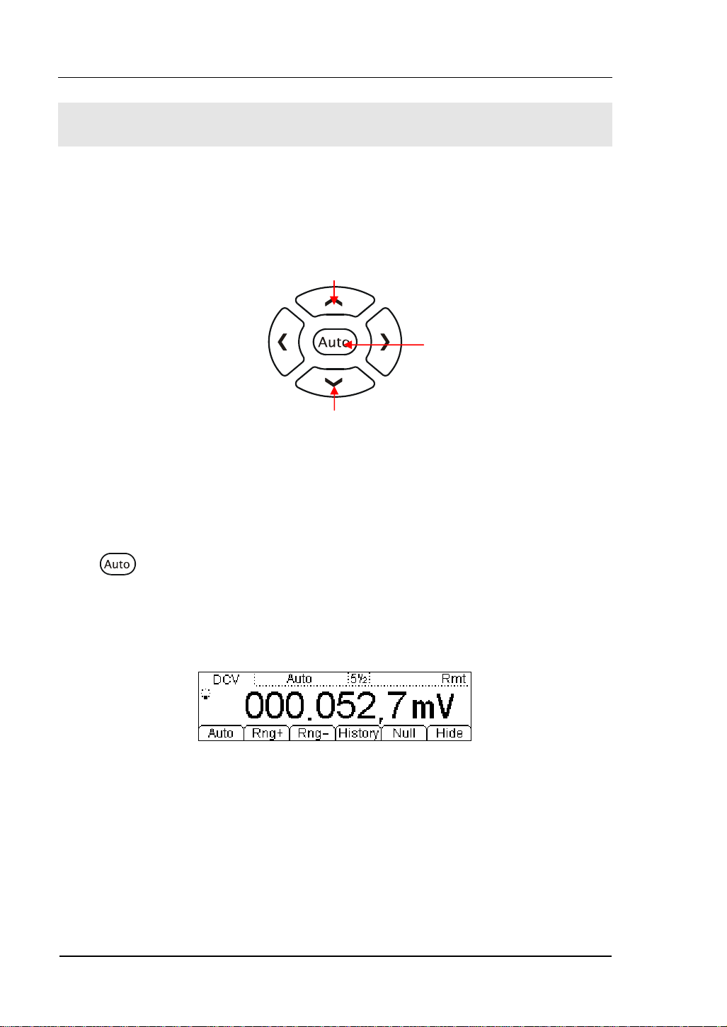
To Choose Reading Resolution
The measurement reading resolutions (the accuracy) are 4 1/2, 5 1/2, 6 1/2 digits.
Reduce the index
Increases the index
Figure 1- 57 The Digits Resolution Control Keys
Methods:
Use the left and/or right direction key to adjust the desired measurement resolution.
Press left button to decrease accuracy, press right button to increase accuracy.
The digits resolving index Selection
(1). Each precision of the measure function can be set separately without influence.
(2). Choose the reading precision of 6 1/2 bit when measuring AC for best results.
(3). Save the digits resolving index in volatile memory.
1-34
© 2007 RIGOL Technologies, Inc.
User’s Guide for DM3000 Series
Page 47

RIGOL
To Choose Data Digit Display
Function to set up data display format; 5, 6 or 7 digits (Default: 5 digits).
Figure 1- 58 7 Digits Data
Figure 1- 59 6 Digits Data
Figure 1- 60 5 Digits Data
NOTE
In high-accuracy measurement, if users need to show less data digit, it can show
fewer digits for user-friendly reading.
© 2007 RIGOL Technologies, Inc.
User’s Guide for DM3000 Series
1-35
Page 48
RIGOL
To Choose Range Options
Use “manual” selection or “automatic” to choose measurement range. The
“automatic” allows the instrument to determine the most appropriate range while for
better performance choose the “manual” method.
Increased range
Automatic
selection range
Reduced range
Figure 1- 61 Choice Range Options Keys
Methods 1:
Use up and down direction keys to adjust the Range. Press Up to increase the range,
press Down to reduce the range.
Press key, to select the automatic method.
Methods 2:
Use the menu option keys to adjust the range as shown in the following
Figure 1- 62.
Figure 1- 62 Choice Range Options Menu
1-36
User’s Guide for DM3000 Series
© 2007 RIGOL Technologies, Inc.
Page 49
RIGOL
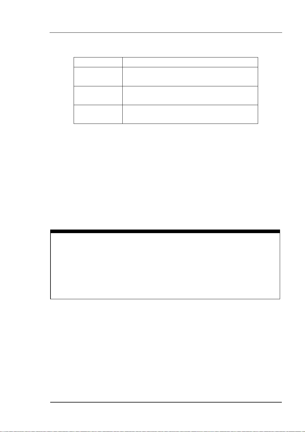
Table1- 13 Choice Range Option Menu
Option Menu Explain
Auto
Range+
Range-
Start automatically adjustment range, and
banned manually adjustment range.
Start manually increased range, and banned
automatically adjustment range.
Start manually reduced range, and banned
automatically adjustment range.
Operation description:
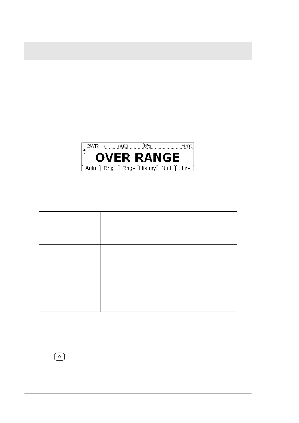
z When the input signal is beyond the current scope of the measurement range, the
multimeter will show “OVER RANGE”.
z After restarting and remote- replacement, range options will turn back default
option “Automatic choice range”.
z When testing the Continuity and Checking the diodes, the range option are fixed.
The range of Continuity is 2KΩ while the diodes are 2V
DC.
NOTE
Other functions of the direction keys:
At measurement parameters setting menu, press the up and down keys to choose
setting areas.
At data input interface, press up and down keys to change the number.
Press left and right keys to change the different digits.
© 2007 RIGOL Technologies, Inc.
User’s Guide for DM3000 Series
1-37
Page 50

RIGOL
To Control Trigger Options
Use or to trigger the multimeter. When the multimeter is powered up, the
key will be on, indicating means this function is running.
Figure 1- 63 Trigger Control Keys
Multimeter triggering options include Automatically, Single and Hold.
Auto Triggering
Press
measurement configuration.
Single Triggering
Press
by a sample count entered.
Holding Triggering
Press
display.
key once, it takes continuous readings at the fast rate the specified
key the multimeter takes one reading, or a number of readings specified
key, it allows capturing and holding a stable reading on the front panel
NOTE
Press button, during Remote Mode, to switch back to the local mode.
1-38
User’s Guide for DM3000 Series
© 2007 RIGOL Technologies, Inc.
Page 51

RIGOL
Chapter 2 Operating Your Multimeter
By now the front/rear panel, the function control area and keys, and the ways to set
up the multimeter have been introduced.
This chapter goes through all groups of front-panel buttons and menus, and extends
the knowledge the operation instructions.
Follow the exercises to get the most of the powerful measurement capabilities of the
multimeter.
This chapter covers the following topics:
To Set up Measurement Parameters ( )
To Make Mathematics Operation ( )
To Set up Trigger System ( )
To Save and Recall ( )
To Set up Utility ( )
To Set up High-speed data acquisition ( )
and Multi-route Scanning
Use the built-in help system ( )
© 2007 RIGOL Technologies, Inc.
User’s Guide for DM3000 Series
2-1
Page 52

RIGOL
To Set up Measurement Parameters
Press key to enter the Measurement Menu for setting to set up the
measurement parameters. Users may use the factory defaults or establish desired
configurations.
The Measurement parameters Menu includes: Conti, Filter, Res, Null, and Ratio. To
change these parameters, satisfy the dissimilar condition of the measurement
request.
Table 2- 1 Menu Description
Function
Menu
Description
Conti Set up the resistance value in continuity test.
Filter Choose the AC filter bandwidth.
Res Choose the DC voltage input impedance.
Null Set up null value.
Ratio Measured the ratio of two DC voltage signal.
Freq Measured the frequency of AC signal.
Save all changes, and end the current operation.
2-2
© 2007 RIGOL Technologies, Inc.
User’s Guide for DM3000 Series
Page 53

RIGOL
Continue Resistance
Set up the continue resistance value in the short test menu. When the measured
resistance is below limit, the DM3000 will beep to indicate the circuit continuation.
The continue resistance is only using at Continue Test.
Press Æ Conti, enter the menu shown below:
Figure 2- 1
Use direction keys to change the parameter values:
Press left and right directional keys to choose different digits. Press up and down
keys to change the current digit value.
Continue Resistance
The range of continue resistance is 1Ω~2000Ω. The default value is 10Ω.
The continue resistance value stored in the nonvolatile memory, the resistance still
keep when the power is off.
© 2007 RIGOL Technologies, Inc.
User’s Guide for DM3000 Series
2-3
Page 54

RIGOL
AC Filter
There are three settings at the AC Filter menu. Choose the appropriate setting for
more accurate measurements. This function applies AC Voltage and AC Current
measurement only.
Press Æ Filter, enter the menu shown below:
Figure 2- 2
Table 2- 2 AC Filter Menu Description
Function
Menu
Description
Slow Set up the filter with low speed.
Mid Set up the filter with to middle speed.
Fast
Set up the filter with high speed.
Save all changes, back to a higher level menu.
Table 2- 3 AC Filter Parameters Characteristics
AC Filter Options Input Frequency Setting Timer
Slow
Mid
Fast
3Hz~300kHz
20Hz~300kHz
200Hz~300kHz
1.2 reading/s
0.5 reading/s
0.3 reading/s
AC Filter
The AC Filter Parameters are saved in the volatile memory, the data will lose when
the power is off.
The default value of AC Filter Parameters is “Mid” (middle).
2-4
© 2007 RIGOL Technologies, Inc.
User’s Guide for DM3000 Series
Page 55

RIGOL
DC Input Impedance
The options of input resistance for DC value measurements are 10MΩ and >10GΩ.
For 200mV, 2V, 20V measuring ranges, choose >10MΩ for better result.
Press Æ Res, enter the menu shown below:
Figure 2- 3
Table 2- 4 DC Input Resistance Menu Description
Function
Menu
10MΩ Set up the DC Input Impedance to 10MΩ.
>10GΩ Set up the DC Input Impedance to >10GΩ.
Save all changes, back to a higher level menu.
DC input resistance selection:
(1). While the DC input resistance is selected to 10MΩ, the input resistance of all
measurement range is 10MΩ;
(2). While the DC input resistance is selected to >10GΩ, the input resistance for
200mV, 2V and 20V measurement range is >10GΩ; for 200V and 1000V
measurement range is kept at 10MΩ.
Description
© 2007 RIGOL Technologies, Inc.
User’s Guide for DM3000 Series
2-5
Page 56

RIGOL
Null Measurement
The DM3000 null settings is available for DC voltage, AC voltage, DC current, AC
current, resistance, frequency/period, and capacitance measurements.
With null setting each measurement is the difference between a stored null value
and input signal. The null measurement enhance the accuracy by off set test lead
impedance. It is particularly important prior for making capacitance measurements.
The formula used for calculating null measurements is:
Result = reading - null value
The null value is adjustable, and can be set to any value between 0 and
the highest range, for the present function.
Press Æ Null, the display shows:
±120% of
2-6
Figure 2- 4
Table 2- 5 Null Measurement Menu Description
Function Menu Description
Current Use the measured value as the null value.
Clear Set the value to be zero.
On/Off Turn the Null function on or off.
Save all changes, back to a higher level menu.
© 2007 RIGOL Technologies, Inc.
User’s Guide for DM3000 Series
Page 57

RIGOL
Null measurement parameters setting methods:
(1). In operation interface press Null button, use the current value to be Null value.
(2). To select null function. Start null function, the multimeter will use the current
value to Null value.
(3). In Null setting display interface, it uses the Direction Keys to input null value.
© 2007 RIGOL Technologies, Inc.
User’s Guide for DM3000 Series
2-7
Page 58

RIGOL
⋅
Ratio Measurement
Use Ratio measurement to measure the ratio of 2 DC voltage signal. Ratio
measurement is only for measuring DC voltage.
Press Æ Ratio, the display shows:
Figure 2- 5
Table 2- 6 Ratio Measurement Menu Description
Function
Menu
ON Enable the Ratio Measurement Function.
OFF Disable the Ratio Measurement Function.
Save all changes, back to a higher level menu.
The method of the radio measurement:
DC Voltage
Ratio=
DC Reference Voltage
(1). Measuring Sense Terminal, for measuring reference DC voltage. Default
automatic range option under 10V.
(2). Measuring Input Terminal, for measuring DC voltage. The measuring voltage
scope is under 10V.
(3). Input LO Terminal and Sense LO Terminal must have a common reference
value, and the voltage difference cannot surpass ±1V.
Re
VoltageDC
tagefrenceVaolDC
Description
2-8
User’s Guide for DM3000 Series
© 2007 RIGOL Technologies, Inc.
Page 59
RIGOL
V
Basic measurement:
1. Connect test leads shown in
Figure 2- 6; red test leads to the HI Terminal, black
test leads to the LO Terminal.
2. Press
to select the DC Voltage measurement function.
3. Choose the appropriate measurement range.
4. Set up the DC Ratio Measurement.
Press Æ Ratio Æ On, to start the DC Ratio Measurement.
5. Lead test leads into circuit, start to measure.
Signal
oltage
Reference
Voltage
Figure 2- 6 Ratio Measurement
© 2007 RIGOL Technologies, Inc.
User’s Guide for DM3000 Series
2-9
Page 60

RIGOL
Frequency Measurement
Frequency measurement function is used for measuring the frequency of AC signal
(voltage and current) only.
Press Æ Freq, the display shows:
Figure 2- 7
Table 2- 7 Ratio Measurement Menu Description
Function
Menu
Description
ON Activate the Frequency Measurement Function
OFF Deactivate the Frequency Measurement Function
Save all changes, back to a higher level menu.
Basic measurement:
1. Connect test leads as shown in Figure 2-9; red test lead to the HI Terminal, black
test lead to the LO Terminal.
2. Press
or to select the AC voltage or current measurement function.
3. Choose the appropriate range.
4. Set up the AC Frequency Measurement.
Press Æ Freq Æ On, to start the AC Frequency Measurement.
Press to save all changes, back to a higher level menu.
2-10
© 2007 RIGOL Technologies, Inc.
User’s Guide for DM3000 Series
Page 61

RIGOL
5. Lead test leads into circuit, start to measure.
AC Voltage
Figure 2- 8
AC Current
Figure 2- 9
Figure 2- 10 Frequency Measurement Display Interface
© 2007 RIGOL Technologies, Inc.
User’s Guide for DM3000 Series
2-11
Page 62
RIGOL
Math Functions
Press key, the display shows:
Figure 2- 11
The DM3000 provides five math functions: Null, statistic, dB, dBm and Limit testing.
Only one of these math functions can be enabled at a time, and remains in effect
until change.
In Math function interface, choose the required math function. Press On to start the
Math function.
Math functions are the combination of mathematical and the basic measurement
operation. However, not all combinations are supported. In such case the math
function will automatically turn off.
Table 2- 8 Math Function Menu Description
2-12
Function
Menu
Statistic
dB
dBm
Limit
ON/OFF
Settings Description
Reading statistic functions, including: Max, Min,
Average, and number of measurement.
The dB measurement is the difference between
the input signal and a stored relative value.
The dBm function is logarithmic, and is based on
a calculation of power delivered to reference
impedance.
The limit test function performs pass/fail testing
with upper and lower limits that you specify.
ON
OFF
Turn on Math function.
Turn off Math function.
Save all changes, back to a higher level menu.
© 2007 RIGOL Technologies, Inc.
User’s Guide for DM3000 Series
Page 63

RIGOL
Table 2- 9 shows the supported combination.
Table 2- 9 Math Function is used for the following measurement applications
Measurement
DC Voltage Support Support Support Support
AC Voltage Support Support Support Support
DC Current Support Support
AC Current Support Support
Resistance
Resistance
Frequency Support Support
Continuity
Capacitance Support Support
Supported the Math function
Function
2-Wire
4-Wire
Statistic dB dBm Limit
Support Support
Support Support
Period Support Support
Diodes
Ratio Support Support
© 2007 RIGOL Technologies, Inc.
User’s Guide for DM3000 Series
2-13
Page 64

RIGOL
Math Functions Selective
The DM3000 provides five math functions: Null measurements, Total measurements,
dB measurements, dBm measurements, and Limit testing. Only one of these math
functions can be enabled at the same time, and remains in effect until you turn it off
or change it.
Press
key, the display shows:
Figure 2- 12
Table 2- 10 Math Functions Menu Function Description
Function
Menu
Statistic
dB
Settings Description
Reading statistic functions, including: Max, Min,
Average, and number of measurement.
The dB measurement is the difference between
the input signal and a stored relative value.
The dBm function is logarithmic, and is based on
dBm
a calculation of power delivered to reference
impedance.
Limit
The limit test function performs pass/fail testing
with upper and lower limits that you specify.
2-14
ON/OFF
ON
OFF
Turn on Math function.
Turn off Math function.
Save all changes, back to a higher level menu.
© 2007 RIGOL Technologies, Inc.
User’s Guide for DM3000 Series
Page 65

RIGOL
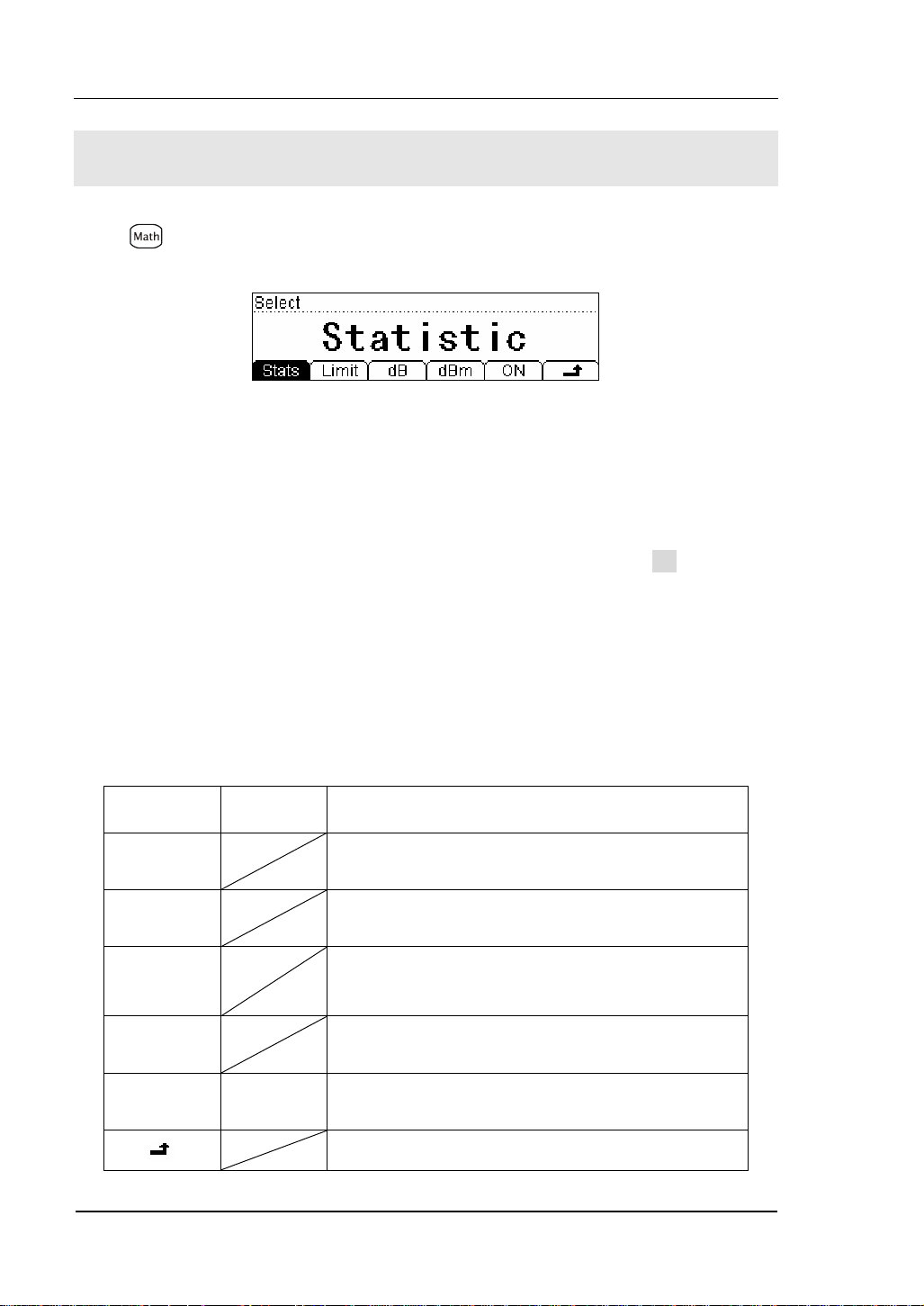
1. Statistic Measurement
The Statistic function is for DC voltage, AC voltage, DC current, AC current,
resistance, frequency/period, and capacitance measurement.
The front panel can display the statistical data for any set of readings: average (Ave),
maximum (Max), minimum (Min), and which can read with All function and the
number of samples taken (Total).
Figure 2- 13
Press Æ Stats, the display shows:
Figure 2- 14
Table 2- 11 Statistic Measurement Menu Function Description
Function Menu Description
Max (Maximum)
Maximum value from a set of measurements.
Min (Minimum) Statistical measurement all reading Min value.
Ave (Average) Statistical measurement all reading Average value.
All The complete a set of measurement.
Save all changes, back to a higher level menu.
© 2007 RIGOL Technologies, Inc.
User’s Guide for DM3000 Series
2-15
Page 66

RIGOL
2. Limit Measurement
Use the Limit test function to perform pass/fail testing with respect to specified
upper and lower limits. The limits can be set to any value between 0 and ±120% of
the highest range of the current function. The upper limit must be positive than the
lower limit.
Press Æ Limit, the display shows:
Figure 2- 15
Table 2- 12 Limit Measurement Menu Function Description
Function
Menu
Settings Description
High Set the desired Upper limit.
Low Set the desired Lower limit.
Save all changes, back to a higher level menu.
The range of Limit function:
(1). The limit value scope is 0%~±120% of the current measurement range.
(2). The upper limit value should be always bigger than the lower limit value.
2-16
© 2007 RIGOL Technologies, Inc.
User’s Guide for DM3000 Series
Page 67

RIGOL
3. dB Measurement
The dB function applies to AC voltage and DC voltage measurements only.
Each dB measurement is different between the input signal and a stored relative
value, with both values converted to dBm.
Press Æ dB, enter the menu shown below:
Figure 2- 16
Table 2- 13 dB Measurement Function Menu Function Description
Function
Menu
Description
Default Use the default value.
Save all changes, back to a higher level menu.
dB =10xLog
[ (Reading2 / R
10
) / 0.001W ] – (dB setting value)
REF
expressed measuring the resistance value in the actual electric circuit.
R
REF
Range of the dB setting value: -120 dBm ~ +120 dBm. The default is 0 dBm.
You can either let the instrument automatically measure this value, or you can enter
a specified value.
© 2007 RIGOL Technologies, Inc.
User’s Guide for DM3000 Series
2-17
Page 68
RIGOL
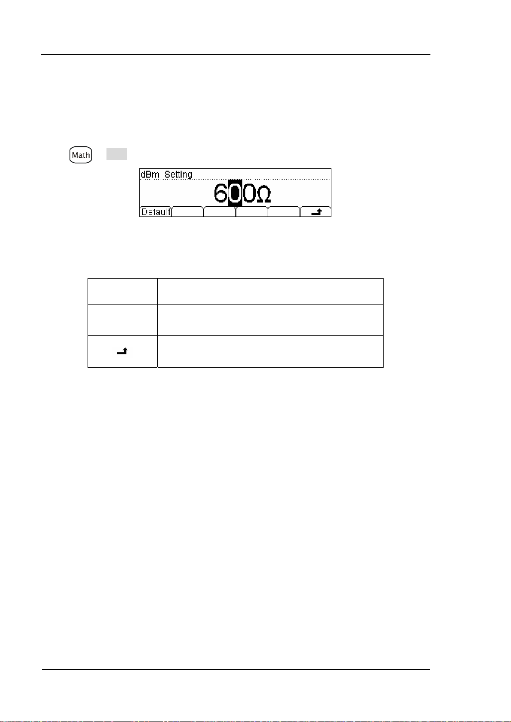
4. dBm Measurement
This function applies to AC voltage and DC voltage measurements only.
The dBm function is logarithmic, and is based on a calculation of power delivered to
a reference resistance, relative to 1 milliwatt.
Press Æ dBm, the display shows:
Figure 2- 17
Table 2- 14 dB Measurement Function Menu Function Description
Function
Menu
Description
Default Use the default value.
Save all changes, back to a higher level menu.
The computation method of the dBm:
dBm = 10 x Log
expressed measuring the resistance value in the actual electric circuit.
R
REF
[ (Reading2 / R
10
) / 0.001W ]
REF
2-18
© 2007 RIGOL Technologies, Inc.
User’s Guide for DM3000 Series
Page 69

RIGOL
To Set Up Triggering Parameter Function
The DM3000 triggering system allows generation of triggers either manually or
automatically, and taking multiple readings per trigger. The DM3000 also allows
setting of an internal triggering level, and to set up pre-triggering.
Selecting a Trigger Source
Specify the source of a trigger. The power–on default is auto triggering. Other types
of triggering are described in the following sections.
The power–on trigger default mode was auto trigger (RUN) mode. Press
to the hold trigger mode. Press
reading is taken, and another reading is taken each time, the
to go to the single trigger mode, a single
button you
pressed, or when a hardware trigger is received on the Ext Trig connector.
Figure 2- 18
Table 2- 15 Trigger Parameters Setting Menu Function Description
Function
Menu
Auto
Setting system Auto trigger and reading Hold meter
reading measurement schemes..
Description
to go
Single Setting Single manual trigger parameter.
Ext Setting external triggering.
VMC
© 2007 RIGOL Technologies, Inc.
Setting the output signal pulse width at sampling
ending output signal.
Save all changes, back to a higher level menu.
User’s Guide for DM3000 Series
2-19
Page 70

RIGOL
Auto Triggering
Auto triggering takes continuous measurement at the highest sample rate for the
specified measurement configuration (function, range, resolution, and so forth).
Auto trigger is the default trigger mode at system power up.
Press Æ Auto, the display shows:
Figure 2- 19
Table 2- 16 Auto Trigger Function Menu Description
Function
Menu
Interval
Setting Description
Set interval time in 400~2000ms.*
Hold ON/OFF Set turn the Reading Hold function ON or OFF.
Save all changes, back to a higher level menu.
Interval time:
The delay between the trigger signal and the first sample taken. This is useful in
applications when the input signal settles before taking a reading, or for pacing a
burst of readings.
z The trigger delay may be set from 400 to 2000 ms.*
z The continuity and diode test functions ignore the trigger delay.
z The default trigger delay automatically set if no specified value entered.
z If a trigger delay entered, it will is used for all measurement functions (except
continuity and diode test).
*NOTE:
The trigger interval time is 400~2000ms (6 1/2), 200~2000ms (5 1/2) and
100~2000ms (4 1/2). The range of the interval time will be different in different
resolving index.
2-20
User’s Guide for DM3000 Series
© 2007 RIGOL Technologies, Inc.
Page 71

RIGOL
Reading Hold
The reading hold mode captures and holds a reading on the front panel display when
a stable reading is detected. The system Hold ranges are 0.01%, 0.1%, 1%, and
10%.
Press Æ Auto Æ Hold, the display shows:
Figure 2- 20
Table 2- 17 Reading Hold Function Menu Description
Function
Menu
On/Off
Turn on/off the reading hold function.
Description
0.01% Set the hold scope is 0.01%.
0.1% Set the hold scope is 0.1%.
1%
10%
Set the hold scope is 1%.
Set the hold scope is 10%.
Save all changes, back to a higher level menu.
© 2007 RIGOL Technologies, Inc.
User’s Guide for DM3000 Series
2-21
Page 72

RIGOL
Reading Hold Function
Start the Reading Hold Function, the hold measurement use the following rules
judge the reading count:
When Max() - Min() ≤ hold range x ReadingN, the multimeter hold ReadingN on the
display.
The display update a new reading basing on the current value and the three
preceding measurements before the reading was hold:
Max (ReadingN, ReadingN-1, ReadingN-2, ReadingN-3)
Min (ReadingN, ReadingN-1, ReadingN-2, ReadingN-3)
NOTE
When Reading Hold started, the input resistance was set to 10MΩ for all DC voltage
range to reduce noise arising from the open-loop testing.
2-22
© 2007 RIGOL Technologies, Inc.
User’s Guide for DM3000 Series
Page 73

RIGOL
Single Triggering
The multimeter takes one reading, or a number of readings specified by a sample
count you enter, each time
Press Æ Single, the display shows:
Table 2- 18 Single Trigger Function Menu Description
Function
Menu
Single Set a sample count, the default sample count is 1.
Save all changes, back to a higher level menu.
press.
Figure 2- 21
Description
Sample Count
While the multimeter receives a single trigger signal, the multimeter takes one
reading or a number of readings.
The number of sample count range from 1 to 50,000. The factory default is 1.
© 2007 RIGOL Technologies, Inc.
User’s Guide for DM3000 Series
2-23
Page 74

RIGOL
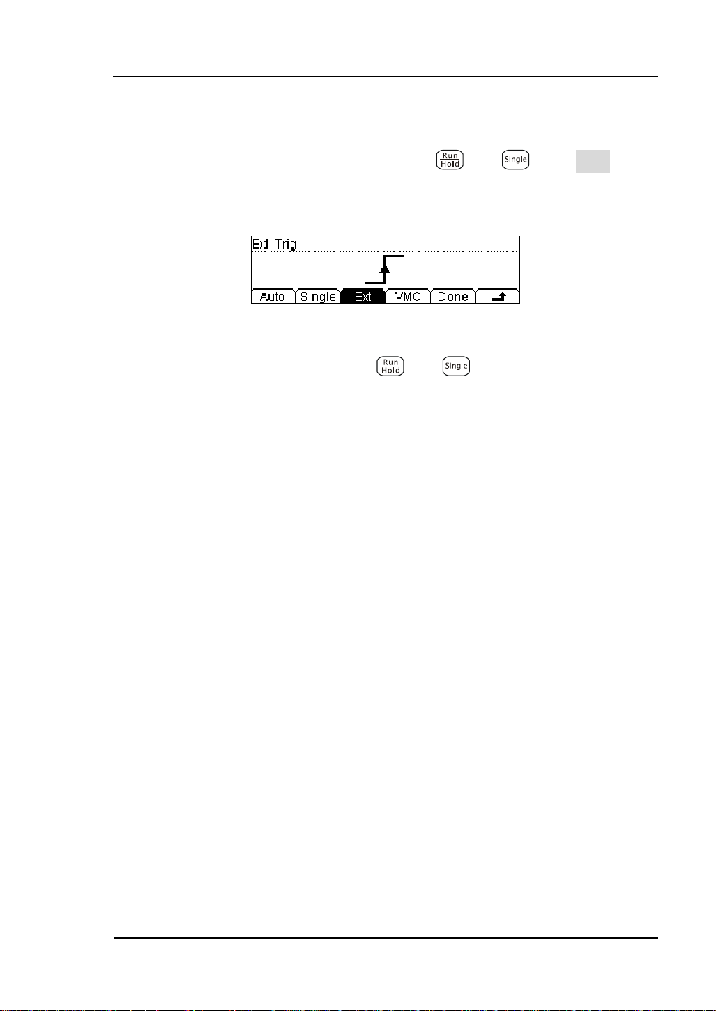
External Triggering
is used to set the parameter which initiates the triggering function. It requires to
set the following parameter: the Rise edge, the Fall edge, HiLev (high level) and
LoLev (low level). Press Done to start the external triggering, the keys and
on the front panel will be off to indicate the instrument using external triggering
mode.
Press Æ Ext, the display shows:
Figure 2- 22 The Interface of the External Triggering
Triggering modes: the rise edge, the fall edge, high level and low level.
2-24
© 2007 RIGOL Technologies, Inc.
User’s Guide for DM3000 Series
Page 75
RIGOL
Using the triggering function
Auto, hold and Single trigger can switch by using and , press Done button
on the triggering interface to startup the external triggering.
Figure 2- 23 The Interface of the External Triggering
When external triggering start, the key
be off.
and on the front panel both will
© 2007 RIGOL Technologies, Inc.
User’s Guide for DM3000 Series
2-25
Page 76

RIGOL
To Set up the VMC
At external triggering mode, when the data sampling is over, the instrument outputs
a pulse signal at VM Comp located on the rear panel. The output pulse width can be
adjusted.
Press Æ VMC, the display shows:
Figure 2- 24
Table 2- 19 The Explanation of the External Triggering(polarity: positive)
Function
Menu
Polar
Setting Explanation
Pos
Neg
Setting the pulse signal’s polarity.
PWidth Setting the pulse width.
Store the changing and back to
the higher menu.
The VMC function output
(1). At external triggering mode, when the data sampling is over, the instrument will
output a pulse signal to indicate operation completed.
(2). At external triggering mode, when operating math limited value, the instrument
will export a pulse signal to indicate out of limits detected.
2-26
© 2007 RIGOL Technologies, Inc.
User’s Guide for DM3000 Series
Page 77

RIGOL
Store and Recall
To Storage and Recall function enable save, load, and delete the measurement data,
parameters and sensor files in the local storage as well as in a USB storage.
Press
key, the display shows:
Figure 2- 25
Table 2- 20 Storage and Recall Function Menu Description
Function
Menu
Setting Description
C:\ (Local)
Disk
A:\ (U-Disk)
Choose Local or U-Disk storage.
Sys Setting/
Meas Data/
Type
MEAS_CSV
Choose the type of the files shown.
…
Read
Load the selected file.
Save Save the file to the specified location.
Erase Delete the selected file.
Save all changes, back to a higher level menu.
© 2007 RIGOL Technologies, Inc.
User’s Guide for DM3000 Series
2-27
Page 78

RIGOL
Local/U-Disk Storage
Local storage block is built-in the multimeter. The U-Disk storage will be a USB flash
disk.
Press
key, enter the menu shown below:
Figure 2- 26 The U-Disk Storage Interface
Table 2- 21 Storage and Recall Function Menu Description
Function
Menu
Explore
Setting Description
Choose Local storage or U-Disk.
Sys Setting/
Meas Data/
MEAS_CSV/
LOG_CSV
Type
Data log/
Choose the type of the files shown.
Sensor/
Sensor Data/
Scan Task
Read
Load the selected file.
Save Save the file the specified location.
Erase Delete the selected file.
Save all changes, back to a higher level menu.
2-28
User’s Guide for DM3000 Series
© 2007 RIGOL Technologies, Inc.
Page 79

RIGOL
Document Storage
In local/U-disk storage area, you allowed to save, load and delete parameter, data
and sensor documents.
Choose the storage area of the files
Press Æ Disk, choose Local storage or U-Disk rout. Choose C:\, and the default
fype is “SysSetting”.
Figure 2- 27 The Local storage interface
Choose the storage type of the files
Press Æ Type, choose the type “MeasData” of the files, into the menu shown
below:
Figure 2- 28
Press Æ Type, choose the type “MEAS_CVS” of the files, into the menu shown
below:
Figure 2- 29
Press Æ Type, choose the type “LOG_CVS”, “Datalog”, “Sensor”, “SensorData”,
“ScanTask” of the files, into the menu shown below:
© 2007 RIGOL Technologies, Inc.
User’s Guide for DM3000 Series
2-29
Page 80

RIGOL
Figure 2- 30
NOTE
Store, recall and delete use the same interface.
1) To choose different storage locations, Press Disk, to switch the store
location (C:\(Local) and A:\(U-Disk)).
2) To choose different files types, Press Type, to switch the file type (Data,
Parameter, and Sensor).
3) When the A disk in use, do not remove the U disk.
2-30
© 2007 RIGOL Technologies, Inc.
User’s Guide for DM3000 Series
Page 81
RIGOL
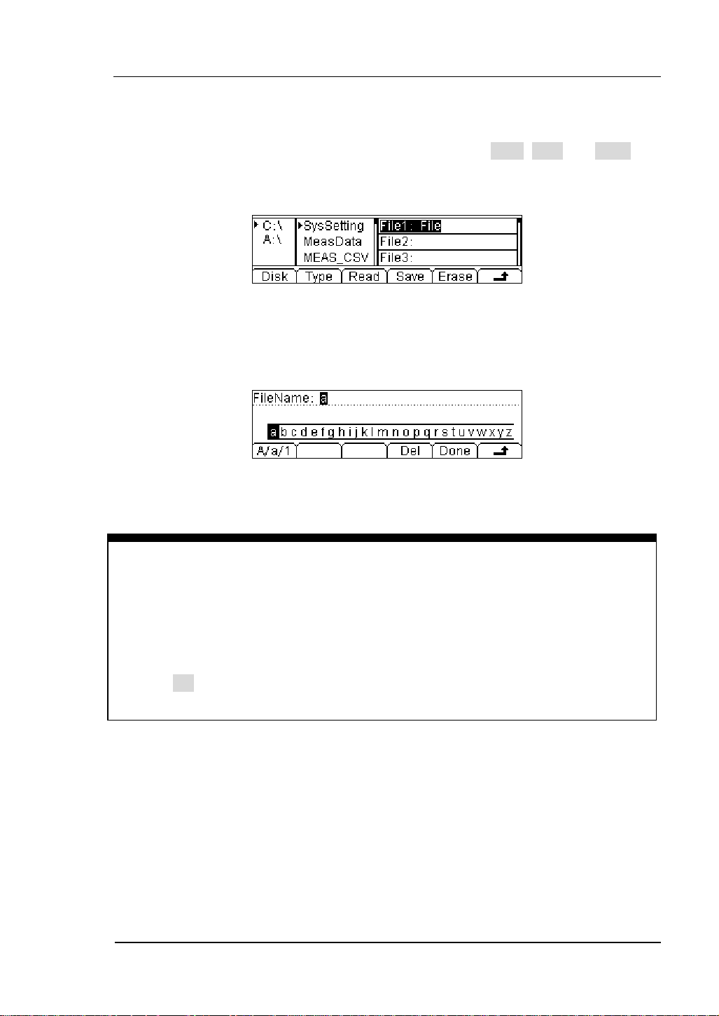
Document Operation
Use the up and down buttons to select the file, then press Read, Save and Erase soft
keys to do the corresponding operation.
Figure 2- 31
To save the file, name the file with letters and/or numbers.
Figure 2- 32
Input Method:
1) Press A/a/1 button to select the Capital letter, Lowercase letter or Numbers.
2) Use the up/down button to close or open the number/letter selection area
display.
3) Use the left/right button to move cursor in FileName or number/letter selection
area.
4) The Delete function can only delete the letter on which the cursor taking place.
© 2007 RIGOL Technologies, Inc.
User’s Guide for DM3000 Series
2-31
Page 82

RIGOL
To Set Up the Utility
The Utility function establishes system parameters, interface parameters, and
calibration.
Figure 2- 33
Table 2- 22 Utility Function Menu Description
Function
Menu
*FPGA Update FPGA Programm
I/O To set up I/O and LAN parameters.
Sys To set up system information configuration.
T/C Test and calibration function.
*Note:FPGA button shows only when U-disk connencted.
Description
2-32
© 2007 RIGOL Technologies, Inc.
User’s Guide for DM3000 Series
Page 83

RIGOL
Set Up the I/O System
Each device on the GPIB (IEEE-488) interface must have a unique address between
0 and 30. The factory set is “1” when shipped.
Press Æ I/O, the display shows:
Figure 2- 34
Table 2- 23 I/O Setting Function Menu Description
Function
Menu
Description
LAN Set up LAN interface.
GPIB Set up GPIB I/O interface.
USB Check USB interface ID.
RS232 Set up RS-232 I/O interface.
Save all changes, back to a higher level menu.
Operation introduction:
Remote control through LAN, GPIB (IEEE-488), USB and RS-232 interface can be
configured. The I/O interface of GPIB, USB and RS-232 only one could be used at the
same time.
© 2007 RIGOL Technologies, Inc.
User’s Guide for DM3000 Series
2-33
Page 84
RIGOL
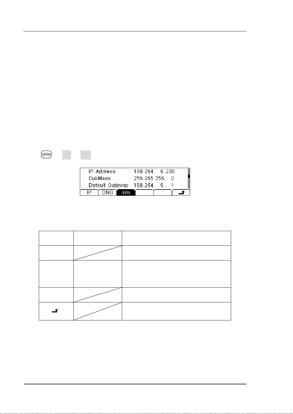
Set Up LAN I/O Parameter
LAN Parameters
Following the procedures to set up a LAN configuration and remote interface from
the front panel.
• IP Address
• Subnet Mask
• Default Gateway
• DNS Server
• Host Name
Press Æ I/O Æ LAN, the display shows:
Figure 2- 35
Table 2- 24 LAN Parameter Function Menu Description
Function
Menu
Setting Description
IP Set IP address and others information.
DNS
Host Name/
Domain Name/
DNS address
Set the host name.
Set the domain name.
Set DNS address.
Info Display current LAN information.
Save all changes, back to a higher level
menu.
2-34
© 2007 RIGOL Technologies, Inc.
User’s Guide for DM3000 Series
Page 85
RIGOL
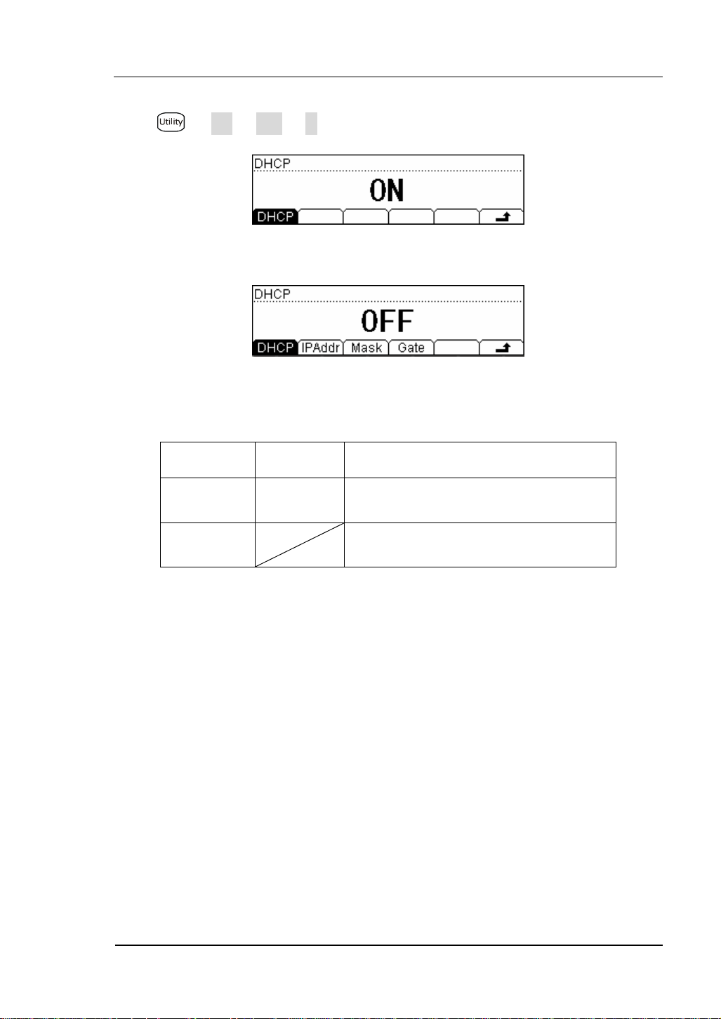
IP Settings
Press Æ I/O Æ LAN Æ IP, the display shows:
Figure 2- 36 DHCP On
Figure 2- 37 DHCP Off
Table 2- 25 IP Setting Menu Description
Function
Menu
DHCP
Done
Setting Description
ON/
OFF
Automatically assigns the IP address
Manual assigns the IP address
Save all changes, back to a higher level
menu.
IP address:
Suggest you ask you network administrator for a unique IP address .IP address can
be saved in non-violet memory.
Subnet mask:
Suggest you ask you network administrator for available subnet mask. Subnet
mask can be saved in non-violet memory.
Gateway:
Suggest you ask you network administrator for a available gateway. Gateway can
be saved in non-violet memory.
© 2007 RIGOL Technologies, Inc.
User’s Guide for DM3000 Series
2-35
Page 86

RIGOL
DNS Settings
Press Æ I/O Æ LAN Æ DNS, the display shows:
Figure 2- 38
Table 2- 26 DNS Setting Menu Description
Function
Menu
Setting Description
Host Set the host name.
DN Set the domain name.
DNS Set the DNS address.
Done
Save all changes, back to a higher
level menu.
Host name:
Configure the strings of the host name, including letters and numbers. Suggest you
ask you network administrator for host name .Host name can be fixed by moving the
direction button to choose the letters. Host name can be saved in non-violet
memory.
Domain Name:
Configure the strings of the domain name, including letters and numbers. Suggest
you ask you network administrator for domain name. Domain name can be fixed by
moving the direction button to choose the letters. Domain name can be saved in
non-violet memory.
DNS server:
Suggest you ask you network administrator for available DNS server. It could be
saved in non-violet memory.
2-36
© 2007 RIGOL Technologies, Inc.
User’s Guide for DM3000 Series
Page 87

RIGOL
Set Up GPIB I/O Parameter
Each device on the GPIB (IEEE–488) interface must have a unique address. You can
set the address of multimeter to any integral value between 0 and 30. The default
address is “1” when the instrument is shipped from the factory.
Press Æ I/O Æ GPIB, enter the menu shown below:
Figure 2- 39
Table 2- 27 GPIB I/O Setting Function Menu Explanation
Function
Menu
Save all changes, back to a higher level menu.
Explanation
© 2007 RIGOL Technologies, Inc.
User’s Guide for DM3000 Series
2-37
Page 88

RIGOL
Set Up RS-232 I/O Parameters
Choose RS-232 (serial data interface) interface. Proper configure the baud rate and
parity to make parameters the same as that settled in your computer. Make sure the
connection line is unbroken. The configuration is saved in inviolate memory and
shown in according menu.
Press Æ I/O Æ RS232, enter the menu shown below:
Figure 2- 40
Table 2- 28 RS-232 Parameter Function Menu Explanation
Function
Menu
Display Explanation
1200
Set RS-232 baud rate as 1200,
2400, 4800, 9600, 19200, 38400,
57600 or 115200.
Baud
.
.
115200
Parity
None
Odd
Even
The parity check include: None, Odd
check, and Even check.
Save all changes, back to a higher
level menu.
Baud rate:
Proper configure the baud rate and parity to make parameters the same as that
settled in your computer.
Available baud rate values are 1200, 2400, 4800, 9600, 19200, 38400, 57600 and
115200. The default value is 2400.
Parity:
Proper configure the parity to make it same as that settled in your computer.
2-38
© 2007 RIGOL Technologies, Inc.
User’s Guide for DM3000 Series
Page 89

RIGOL
System settings
Press Æ System, enter the menu shown below:
Figure 2- 41 The Interface of Setting the System Function
Table 2- 29 System Settings Function Menu Explanation
Function
Menu
Explanation
Lang Select the display interface languages.
Disp Set up the display.
Sound Switch beeper sound On/Off.
Clock Set up the benchmark clock.
Format Set up digit display format.
Cfg Set up or reset the system values.
© 2007 RIGOL Technologies, Inc.
User’s Guide for DM3000 Series
2-39
Page 90
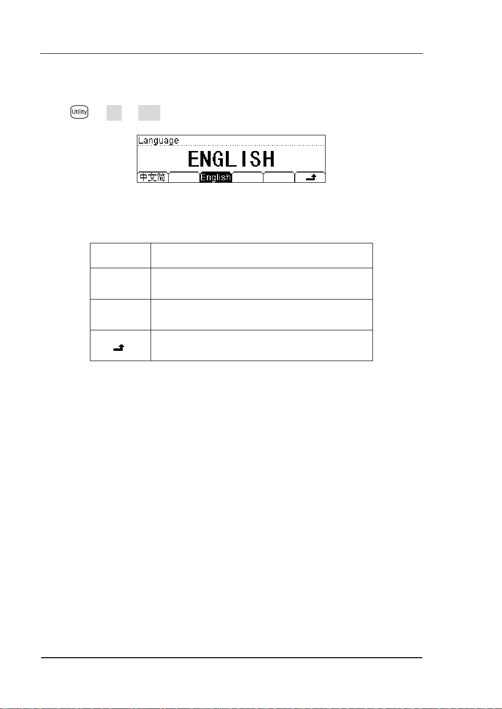
RIGOL
Select languages
DM3000 supports two kinds of languages for users.
Press Æ Sys Æ Lang, enter the menu shown below:
Figure 2- 42
Table 2- 30 System Settings Function Menu Explanation
Function
Menu
中文简
Select the Chinese Simplified.
Explanation
English Select the English.
Save all changes, back to a higher level menu.
2-40
© 2007 RIGOL Technologies, Inc.
User’s Guide for DM3000 Series
Page 91

RIGOL
Set Up the Display
Press Æ Sys Æ Disp, enter the menu shown below:
Figure 2- 43
Table 2- 31 Display Settings Function Menu Explanation
Function
Menu
Bright
Contr
Increase or decrease the display light with left and
right keys.
Increase or decrease the display contrast with left
and right keys.
Explanation
Invert Set to invert display mode.
Save all changes, back to a higher level menu.
© 2007 RIGOL Technologies, Inc.
User’s Guide for DM3000 Series
2-41
Page 92

RIGOL
Beeper On/Off
Press Æ Sys Æ Sound, enter the menu shown below:
Figure 2- 44 Sound On
Figure 2- 45 Sound Off
2-42
© 2007 RIGOL Technologies, Inc.
User’s Guide for DM3000 Series
Page 93
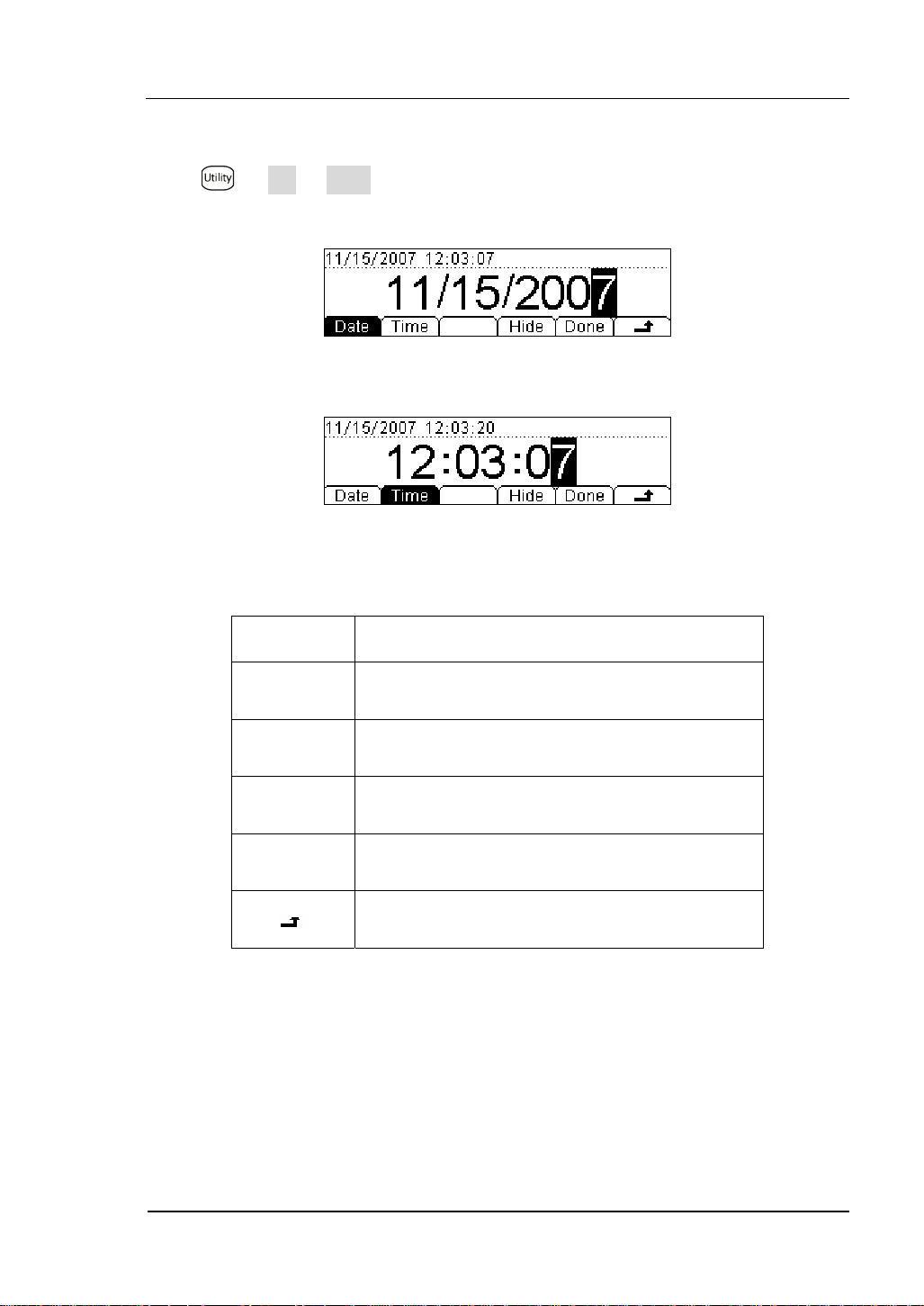
RIGOL
Set Up System date/time
Press Æ Sys Æ Clock, enter the menu shown below:
Figure 2- 46 Data Set Interface
Figure 2- 47 Time Set Interface
Table 2- 32 Clock Settings Function Menu Explanation
Function
Menu
Explanation
Date Set up the date.
Time Set up the time.
Hide Hide data and time display.
Done Save all changes, back to a higher level menu.
Back to a higher level menu, without save.
© 2007 RIGOL Technologies, Inc.
User’s Guide for DM3000 Series
2-43
Page 94
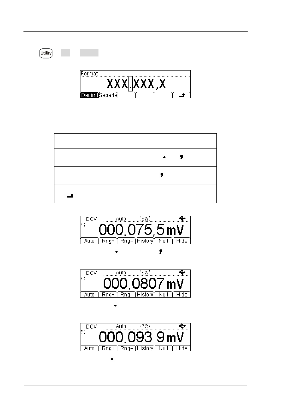
RIGOL
Set Up Digit Format
Press Æ Sys Æ Format, and enter the menu shown below:
Figure 2- 48
Table 2- 33 Digit Format Function Menu Explanation
Function
Menu
Radix
Point
Expresses radix point with or .
Explanation
Separator Expresses separator with , space or none.
Save all changes, back to a higher level menu.
Figure 2- 49 “ ” radix point, “ ” separator
2-44
Figure 2- 50 “ ” radix point, none separator
Figure 2- 51 “ ” radix point, “space” separator
© 2007 RIGOL Technologies, Inc.
User’s Guide for DM3000 Series
Page 95

RIGOL
Figure 2- 52“ ” radix point, “space” separator
Figure 2- 53 “ ” radix point, none separator
Figure 2- 54 “ ” radix point, “ ” separator
Notice:
The decimal and the separator cannot be the same mode, if the decimal is , then
the separator can only be none of space; in contrarily, if the decimal is , then the
separator can only be
, none of space.
© 2007 RIGOL Technologies, Inc.
User’s Guide for DM3000 Series
2-45
Page 96

RIGOL
y
g
gg
g
Trigg
y
g
V
Factory Defaults Setting
Press Æ System Æ Cfg Æ Default, then restart the system to factory default
state. The Parameter shown below:
Table 2- 34 Parameter Lists of Factory Defaults:
Measurement Factor
Defaults Settin
* Continue Resistance 10Ω
Filter Fast
DC Resistance 10MΩ
Digit Resolution 6 ½
Rate Close
Measurement Function DC
range Auto
Math Function Factor
Defaults Settin
Math Stats Close
Math Statistic
Math Register All registers cleared
* dBm Resistance *600Ω
Tri
er Parameter Factory Defaults Settin
Interval
30ms、200ms、400ms according to Digit Resolution
Samples 1
Hold
0.1%
er Sources Auto Trigger
2-46
User’s Guide for DM3000 Series
© 2007 RIGOL Technologies, Inc.
Page 97
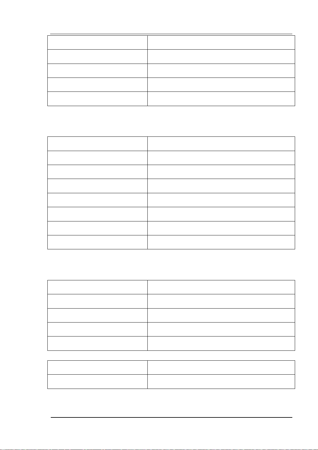
RIGOL
g
g
y
y
g
T
g
)
g
High-Speed Data Log Factor Defaults Settin
Mode Fi
ure
Start Delay 0s
Start Manual Range
Stop Infinit
stem Operations Factor Defaults Settin
S
* Sound * Open
* Separate * Open
Language Chinese
Display Natural model
Clock
ime in main interface
Error queue Errors cleared
Instrument parameter and data no rejigger
Interface Factor Defaults Settin
* GPIB address *7
* I/O *USB
*Baud *9600band
*Parity bit * no (8 digits
Calibration Factor Defaults Settin
Calibration Stats Password
Parameter with (*) are saved in non-volatile Reading Storage
© 2007 RIGOL Technologies, Inc.
User’s Guide for DM3000 Series
2-47
Page 98

RIGOL
High-Speed Data Log
High-speed data log features: display mode settings, start acquire mode settings,
and end acquires mode settings. When finish all settings, press
initiate the high-speed data log.
Setting high-speed data log parameters
Press button, the display shows:
Figure 2- 55 The Main Interface of Data Lot
Table 2- 35 Data Log Parameter Setting Function Menu Description
Function
Menu
Log
Scan
Setting Description
Gather the data of DCV, DCI, 2WR or 4WR
continuously.
Use the scanning mode to test the 16-channels
signals continuously.
Save all changes, back to a higher level menu.
button to
Notice:
Once in the Data Log mod, do not use the Auto range option function but choose the
appropriate range option, thus the Log rates can be guaranteed.
Press Log button enter the data log interface shown below.
Figure 2- 56 The Data Log Setting Interface
2-48
User’s Guide for DM3000 Series
© 2007 RIGOL Technologies, Inc.
Page 99

RIGOL
Table 2- 36 Data Log Menu Description
Function
Menu
Setting Description
1/10m
1/5m
Sa/s
.
.
To set the sample rate with 13 values from
1/10m to 50k/s.
.
50k/s
Start
Stop
Trig
Delay
Timer
REC#
To set the sample manner to be Trig or delay.
To set the data measurement stop manner to
be timer or counter.
Run Start Log the data.
Save all the changes, back to a higher level
menu.
Press Æ Log Æ Sa/s, the interface shows below.
Figure 2- 57 The Data Log Rate Setting Interface
Press Æ Log Æ Start, the interface shows below.
Figure 2- 58 The Data Log Start Manner Setting Interface
© 2007 RIGOL Technologies, Inc.
User’s Guide for DM3000 Series
2-49
Page 100

RIGOL
Press Æ Log Æ Stop, the interface shows below.
Figure 2- 59 The Data Log Stop Manner Setting Interface
2-50
© 2007 RIGOL Technologies, Inc.
User’s Guide for DM3000 Series
 Loading...