

Page 1

User’s Guide RIGOL
Publication Number: UGC03120-1110
Feb. 2014
DM3058/DM3058E Digital Multimeter
© 2008 RIGOL Technologies, Inc. All Rights Reserved
Page 2

Page 3

RIGOL
I
Copyright Information
1. © 2008 RIGOL Technologies, Inc. All Rights Reserved.
2. RIGOL products are protected by patent law in and outsid e of P.R.C..
3. Information in this publication replaces all previously corresponding material.
4. RIGOL Technologies, Inc. r e s e rves the right to modify or change part of or all
the specifications and pricing policies at company’s sole decision.
NOTE: RIGOL is registered trademark of RIGOL Technologies, Inc
User’s Guide for DM3058/DM3058E
Page 4

RIGOL
II
Safety Notices
Review the following safety precautions carefully before operating the instrument
to avoid any personal injuries or damages to the instrument and any products
connected to it. To avoid potential hazards use the instrument as specified by this
user’s guide only.
The instrument should be serviced by qualified personnel only.
Avoid Fire or Personal Injury.
Use Proper Power Cord.
Only the power cord designed for the instrument as authorized in your country
could be used.
Ground The Instrument.
The instrument is grounded through the grounding conductor of the power cord. To
avoid electric shock the instrument groundi ng conductor(s) must be grounded
properly before making connections to the input or output terminals of the
instrument.
Observe All Terminal Ratings.
To avoid fire or shock hazard, observe all ratings and marks on the instrument.
Follow the user’s guide for further ratings information before making connections to
the instrument.
Do Not Operate Without Covers.
Do not operate the instrument with covers or panels removed.
Use Proper Fuse.
Please use the fuse that its voltage and current ratings as specified for the
instrument.
Avoid Circuit or Wire Exposure.
Do not touch exposed connections and components when power is on.
Do Not Operate With Suspected Failures.
If suspected damage occurs with the instrument, have it inspected by qualified
service personnel before further operations.
Keep Well Ventilated.
Do Not Operate in Wet/Damp Conditions.
Do Not Operate in an Explosive atmosphere.
User’s Guide for DM3058/DM3058E
Page 5

RIGOL
III
Keep Product Surfaces Clean and Dry.
The distur ban c e te st of all the mo d els meet th e P/F values of A in the
standard of EN 61326: 1997+A1+A 2+A3, but can’t meet the P/F values
of B.
Input Terminal Protectio n Limitation
Protection limitation is defined for the input terminal:
1. Mai n input (HI and LO) terminal
HI and LO terminals are used for Voltage, Resistance, Capacitance, Continuity,
Frequency and Diodes measurement. Two protection limitations are defined:
1) HI-LO protection limitation: 1000 VDC or 750 VAC. It is the maximum
measurable voltage. The limitation can be expressed as 1000 Vpk.
2) LO-ground protection limitation. LO terminal can safely “float” 500 Vpk
relative to the ground.
The maximum protection limitation of HI terminal relative to the ground is
1000 Vpk. Therefore, the sum of the “float” voltage and the measured voltage
cannot exc eed 1000 Vp k.
2. Sampli ng (HI Sense and LO Sense) terminal
HI Sense and LO Sense are used for 4-Wire Resistance Measurement. Two
protection limitations are defined:
1) HI Sense-LO Sense protection limitation: 200Vpk.
2) LO Sense-LO protection limitation: 2Vpk.
3. Current input (I) terminal
I and LO terminal are used for current measurement. The maximum current
which go through the I terminal is limited to 10A by the fuse on the rear
panel.
NOTE: Voltage on the current input terminal corresponds to voltage on LO
terminal. To obtain favorable protection, specified fuse should be used.
IEC Measurement Category II Overvoltage Protection
To protect against the danger of electric shock, DM3058/DM3058E provides
overvoltage protection for line-voltage mains connections meeting both of the
following conditions:
1. The HI and LO input terminals are connected to the mains under
Measurement Category II conditions, defined below.
2. The mains are limited to a maximum line voltage of 600 VAC.
User’s Guide for DM3058/DM3058E
Page 6

RIGOL
IV
WARNING: IEC Measurement Category II includes electrical devices connected to
mains at an outlet on a branch circuit. Such devices include most small appliances,
test equipment, and other devices that plug into a branch outlet or socket.
DM3058/DM3058E may be used to make measurements with the HI and LO inputs
connected to mains in such devices (up to 600 VAC), or to the branch outlet itself.
However, DM3058/DM3058E may not be used with its HI and LO inputs connected
to mains in permanently installed electrical devices such as the main circuit-breaker
panel, sub-panel disconnected boxes, or permanently wired motors. Such devices
and circuits are subject to overvoltage that may exceed th e protecti o n lim its of
DM3058/DM3058E.
NOTE: Voltages above 600 VAC may be measured only in circuits that are isolated
from mains. However, transient overvoltage is also present on circuits that are
isolated from mains. DM3058/DM3058E is designed to safely withstand occasional
transient overvoltage up to 4000Vpk. Do not use this equipment to measure circuits
where transient overvoltage could exceed this level.
User’s Guide for DM3058/DM3058E
Page 7
RIGOL
V
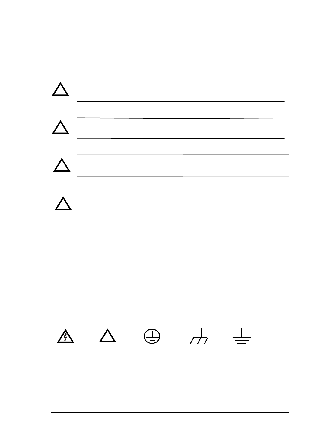
DANGER
indicates an injury or hazard may immediately happen.
WARNING
indicates an injury or hazard may be accessible potentially.
CAUTION
indicates a potential damage to the instrument or other property
might occur.
! ! !
!
Protective
Hazardous
Safety
Test
Chassis
!
Safety Terms and Symbols
Terms in this Manual. These terms may appear in this manual:
WARNING: Warning statements indicate the conditions or practices that
could result in injury or loss of life.
CAUTION: Caution statements indicate the conditions or practices that
could result in damage to this product or other property.
CAT I (1000V) IEC Measurement Category I. The maximum voltage can
be measured by HI-LO terminal is 1000Vpk.
CAT II (600V): IEC Meas urement Category II. Inputs may be connected
to mains (up to 600VAC) under Category II over voltage
conditions.
Terms on the Product. These terms may appear on the product:
Symbols on the Product. These symbols may appear on the product:
Voltage
User’s Guide for DM3058/DM3058E
Warning
Earth
Terminal
Ground
Ground
Page 8

RIGOL
VI
DM3058/DM3058E Overview
RIGOL DM3058/DM3058E is a 5½ dual-display instrument espec ially designed for
high-precision, multifunction, and automation measurements. It realize d a
combination of basic measurement functions and math functions as well as sensor
measurement function.
The DM3058/DM3058E holds a 256 x 64 lattice high-resolution monochrome LCD
display screen with clear keyboard layout and operation hints to make it easier and
agility to use. Besides, it supports multi-interface such as RS-232, USB, LAN (only
for DM3058) and GPIB (only for DM3058).
Main Features:
Real 5½ digits resolution.
Three measurement speeds: 2.5 reading/s, 20 reading/s and 123 reading/s.
Double Display function enables to display two types of characteristic for o ne
signal synchronously.
Two operation m ode s : Preset and Ordinary. Preset mode is abl e to st ore
configuration quickly.
DC Voltage Range between 200mV and 1000V.
DC Current Range between 200μA and 10A.
True-RMS, AC Voltage Range between 200mV and 750V.
True-RMS, AC Voltage Current between 20mA and 10A.
Resistance Range between 200Ω and 100MΩ for 2&4-Wire Resistance
Measurement.
Capacitance Range between 2nF and 10000μF.
Frequency Range between 20H z and 1MHz.
Continuity and Diode Test.
Sensor Measurement function, Built-in Thermocouple compensate in Cold
Terminal.
Abundant Math operations: Max, Min, Average, P/F, dBm, dB, Relative
Measurement, Standard Deviation and Histogram.
Support the storage of data and configuration via USB flash device.
Support USB, GPIB (only for DM3058), RS-232 and LAN (only for DM3058)
interfaces. Support USB-TMC, IEEE 488.2 standard, LXI-C class standard (only
for DM3058) and SCPI language.
In possession of compatible command s w ith both Agilent 34401A and Fluke
User’s Guide for DM3058/DM3058E
Page 9

RIGOL
VII
45.
Record and save the histor y measurement results.
Three kinds of management for Power Supply: PwrOn, Default and Switch.
Enable to store 10 groups o f system configurations in the internal memory and
recall them when required.
Backup or “Clone” all the configurations within instrument into other
DM3058/DM3058E via USB flash device.
Chinese and English menu and online help system.
Provides with control software on PC and application software fo r sensor.
User’s Guide for DM3058/DM3058E
Page 10

RIGOL
VIII
Document Overview
Chapt 1 Quick Start
Guide you to prepare your DM3058/DM3058E and know about the Front/Rear Panel
and User interface.
Chapt 2 Panel Operation
Introduce you ho w to op era te DM3058/DM3058E via Front Panel.
Chapt 3 Application Examples
Introduce you how to use strong measurement functions of this instrument easily
through examples.
Chapt 4 Troubleshooting
Provide you some general troubleshooting.
Chapt 5 Measurement Tutorial
Guide you to eliminate the errors that may appear during your measurement and
obtain accurate result.
Chapt 6 Characteristics
List specifications and characteristics.
Chapt 7 Appendix
Information about accessor ies, warranties, services and supports and the like.
User’s Guide for DM3058/DM3058E
Page 11

RIGOL
IX
Contents
DM3058/DM3058E Overview ........................................................................ VI
Chapter 1 Quick Start ........................................................................... 1-1
General Inspection ..................................................................................... 1-2
Handle Adjustment .................................................................................... 1-3
The Front Panel ......................................................................................... 1-4
The Rear Panel .......................................................................................... 1-5
Power On .................................................................................................. 1-6
User Interface ........................................................................................... 1-7
Double Display ..................................................................................... 1-7
Single Display ....................................................................................... 1-7
Chapter 2 Front Panel Operation .......................................................... 2-1
To Select Range......................................................................................... 2-2
To Select Measurement Rate ....................................................................... 2-4
Basic Measurement Functions ..................................................................... 2-5
To Measure DC Voltage ......................................................................... 2-6
To Measure AC Voltage .......................................................................... 2-9
To Measure DC Current ....................................................................... 2-11
To Measure AC Current ........................................................................ 2-13
To Measure Resistance ........................................................................ 2-15
To Measure Capacitance ...................................................................... 2-20
To Test Continuity ............................................................................... 2-22
To Check Diode .................................................................................. 2-24
To Measure Frequency and Period ........................................................ 2-25
Any Sensor Measurement .................................................................... 2-29
Preset..................................................................................................... 2-37
Secondary Function ................................................................................. 2-38
To Control Trigger Options ........................................................................ 2-40
To Set up Measurement Parameters .......................................................... 2-41
Math Functions ........................................................................................ 2-44
Statistic Measurement ......................................................................... 2-45
P/F Measurement ............................................................................... 2-46
dBm Measurement .............................................................................. 2-48
dB Measurement ................................................................................ 2-49
Relative Operation .............................................................................. 2-50
User’s Guide for DM3058/DM3058E
Page 12

RIGOL
X
To Set Up Trigger Parameters .................................................................... 2-51
Auto Triggering ................................................................................... 2-52
Single Triggering ................................................................................. 2-54
External Triggering .............................................................................. 2-55
Store and Recall ...................................................................................... 2-57
To Set Up the Utility ................................................................................. 2-60
Commands ......................................................................................... 2-61
I/O Settings ....................................................................................... 2-62
System Settings .................................................................................. 2-67
Test/Cal ............................................................................................. 2-72
Print .................................................................................................. 2-73
How to Use the Built-in Help System .......................................................... 2-74
Chapter 3 Application Examples .......................................................... 3-1
Example 1: Reading Statistic Functions ....................................................... 3-2
Example 2: Elimination Leads Impedance .................................................... 3-3
Example 3: dBm Measurement ................................................................... 3-4
Example 4: dB Measurement ..................................................................... 3-5
Example 5: P/F Test .................................................................................. 3-6
Example 6: Thermocouple Setting and Measurement ................................... 3-7
Example 7: Reading Hold ......................................................................... 3-11
Example 8: Store and Recall the Preset ...................................................... 3-12
Example 9: Mirror Image Configuration ...................................................... 3-13
Example 10: To Realize Remote Control via LXI (only fo r DM3058) ............... 3-15
Chapter 4 Troubleshooting .................................................................. 4-1
Chapter 5 Measurement Tutorial ......................................................... 5-1
True RMS AC Measurements ...................................................................... 5-1
Crest Factor Errors (non-sinusoidal inputs) .................................................. 5-3
Loading Errors (AC Volts) .......................................................................... 5-4
Application of the Analog Filter ................................................................... 5-5
Chapter 6 Characteristics ..................................................................... 6-1
General Technical Characteristics ................................................................ 6-1
Electric Technique Characteristics ............................................................... 6-2
DC Characteristics ................................................................................ 6-2
AC Characteristics ................................................................................ 6-4
Frequency/Period Characteristics ........................................................... 6-7
Capacitance Characteristics ................................................................... 6-8
User’s Guide for DM3058/DM3058E
Page 13

RIGOL
XI
Other Measurement Characteristics ........................................................ 6-9
Chapter 7 Appendix .............................................................................. 7-1
Appendix A: DM3058/DM3058E Accessories ................................................. 7-1
Appendix B: Warranty ................................................................................ 7-2
Appendix C: General Care and Cleaning ....................................................... 7-3
Appendix D: Con t act Us ............................................................................. 7-4
User’s Guide for DM3058/DM3058E
Page 14

Page 15

RIGOL
1-1
Chapter 1 Quick Start
General Inspection
Handle Adjustment
The Front Panel
The Rear Panel
Power On
User Interface
User’s Guide for DM3058/DM3058E
Page 16

RIGOL
1-2
General Inspection
1. Inspect the shipping container for damage.
Keep the damag ed shipping container or cushioning material until the
contents of the shipment have been checked for completeness and the
instrument has been checked mechanically and electrically.
2. Check the accessories.
Accessories supplied with the instrument are listed in Appendix A of this
guide.
If the contents are incomplete or damaged, please notify the RIGOL Sales
Representative.
3. Inspect the instrument.
In case of any damag e, or defect, or failure, notify the RIGOL Sales
Representative.
If the shipping container is d amaged, or the protective material shows sig ns
of stress, notify the carrier as well as your RIGOL sales office. Keep the
shipping materials for the carrier’s inspection.
RIGOL offices will arrange reparation or replacement at RIGOL’s option
without waiting for claim settlement.
User’s Guide for DM3058/DM3058E
Page 17
RIGOL
1-3
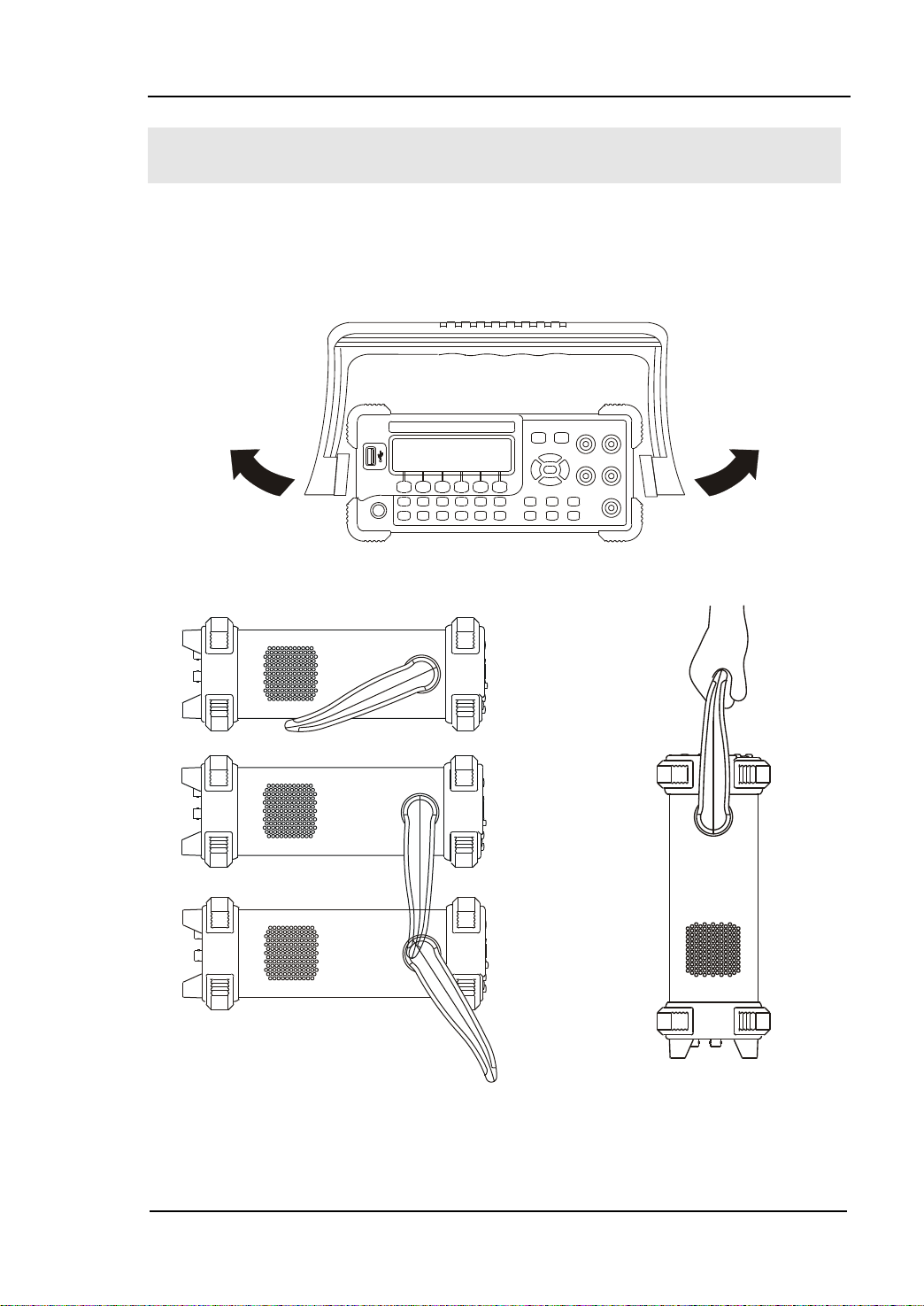
Handle Adjustment
In order to adjust the handle position of the multimeter, please grip the handle in
both sides and pull it outward . Then, rotate the handle to the desi red position as
shown in the figures below.
Figure 1-1 Adjust Handle
Level lo cation Move loc a tion
Figure 1-2 Adjustable location of Handle
User’s Guide for DM3058/DM3058E
Page 18
RIGOL
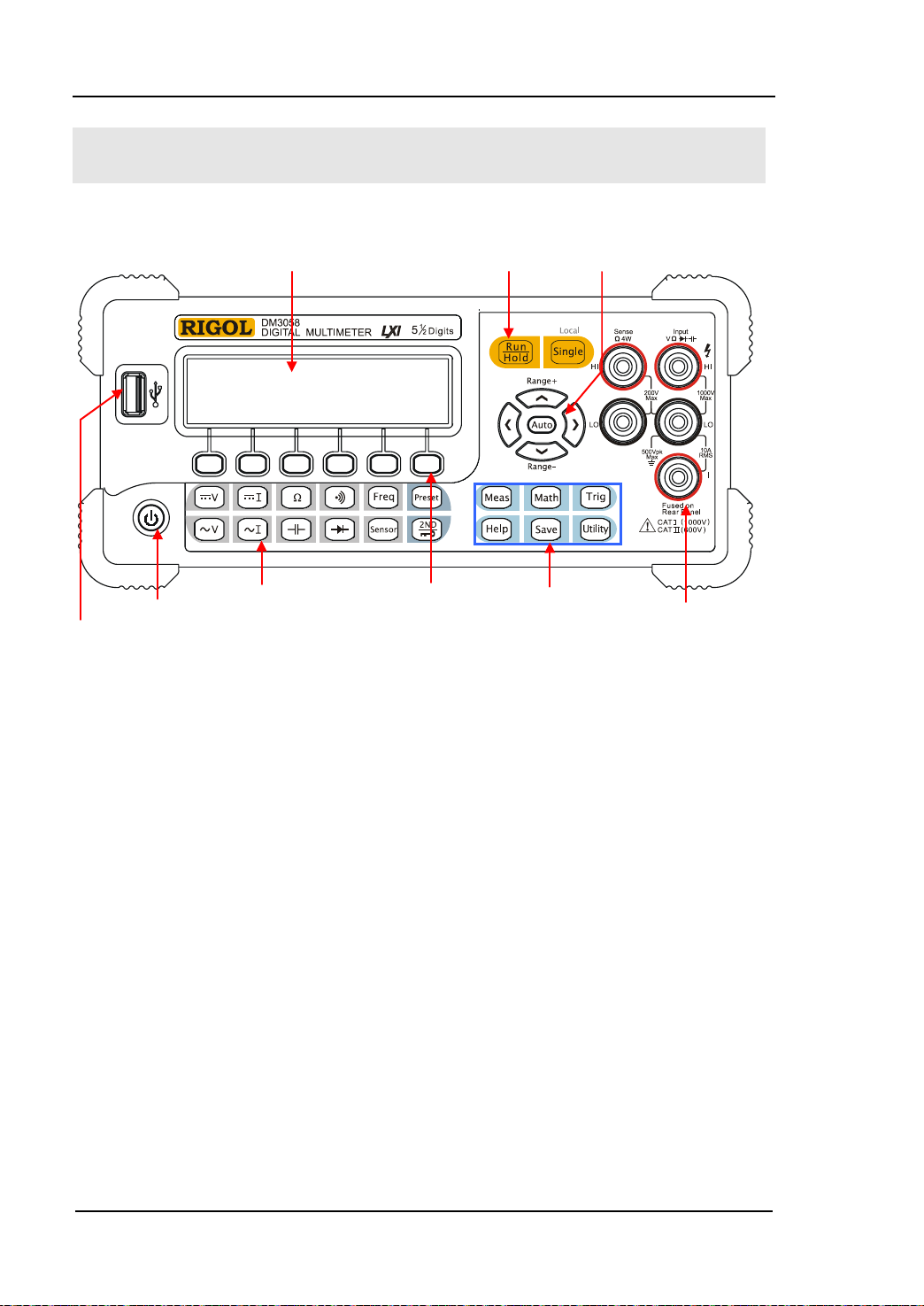
1-4
Yellow District:
Power
Gray District:
Menu
Blue District:
Assistant Function
The Front Panel
USB Host
Key
Measurement
Function Keys
LCD Display
Trigger Control Keys
Operation Keys
Direction Keys
Signal Input Te rmi nal
Keys
Figure 1-3 Front Panel Overview
User’s Guide for DM3058/DM3058E
Page 19
RIGOL
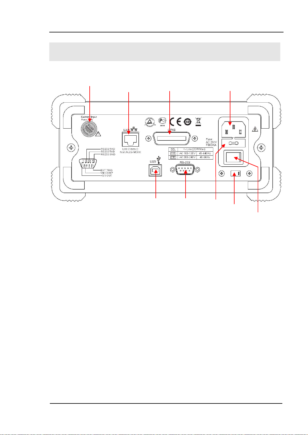
1-5
Power Socket
GPIB
10/100
Current Input Fuse
AC Voltage
Power Fuse
USB Device
Power Switch
The Rear Panel
(IEEE--488)
RS-232
Selector
Figure 1-4 Rear Panel Overview
Explanation: DM3058E does not support GPIB and LAN interfaces.
User’s Guide for DM3058/DM3058E
Page 20

RIGOL
1-6
Power On
Power on the instr ument according to the following steps:
1. Adju s t AC Voltage Selector to “1 15 ” (100~120V, 45~440Hz, AC) or “230”
(200~240V, 45~60Hz, AC) in accordance with power standards in your country;
2. Connect the instrument to AC supply v ia power cord supplied by RIGOL;
3. Turn on the power switch on the rear panel;
4. Press the power key
seconds later.
[1]
Note
: Press System
so as to start the instrument after turning on the power switch on the rear panel.
[2]
Note
: The characters listed under shading ind icate m enu in the multimeter.
[1]
on the front panel, the instrument will be started a few
[2]
Cfg Switch OFF to disable the power key,
User’s Guide for DM3058/DM3058E
Page 21
RIGOL
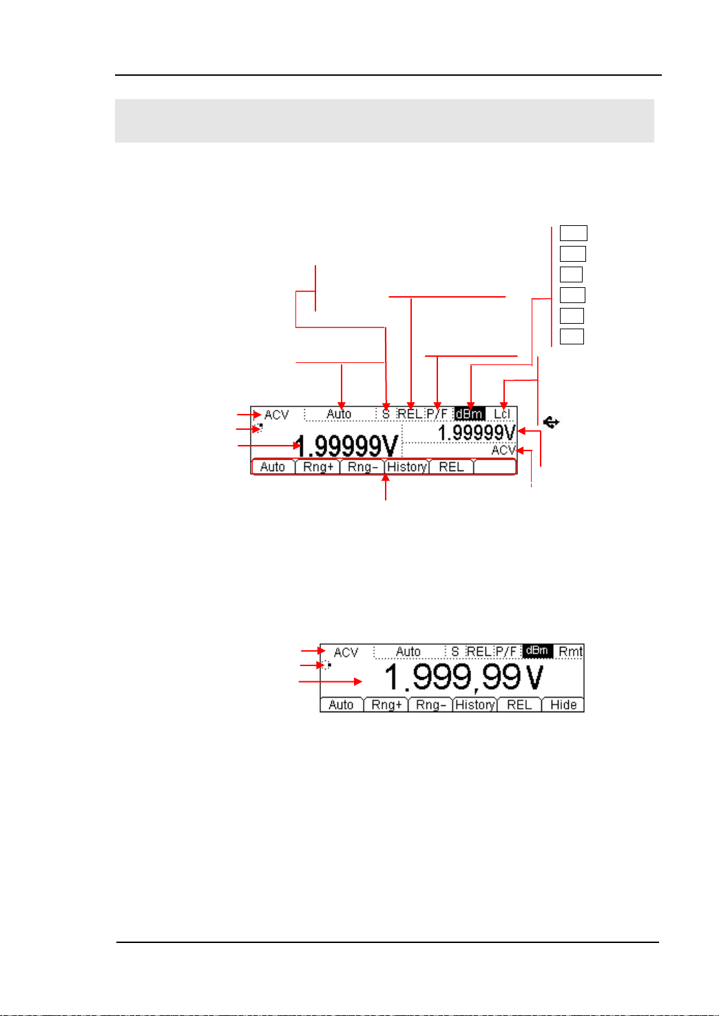
1-7
LXI LXI connection
Main Display
P/F (Open)
REL (Open)
F Fast
Main Display Function
Vice Display Function
Main Display Function
Reading Display
User Interface
Double Display
Run Direction
Reading Display
Single Display
Run Direction
S Slow
M Middle
No icon (Close)
No icon (Close)
Menu
Figure 1-5 User Interface
dB dB
dBm dBm
STA All
MAX Maximum
MIN Minimum
AVG Average
successfully
Rmt Remote Control
Lcl Local Control
USB Storage
Vice Display Value
User’s Guide for DM3058/DM3058E
Page 22

Page 23
2-1
Chapter 2 Front Panel Operation
To Select Range
To Select M easurement Rate
To Measure DC Volt a ge
To Measure AC Voltage
To Mea sure DC Current
To Measure AC Current
To Mea sure Resistance
To Measure Capacitance
To Test Continuity
To Check Diode
To Measure Frequency and Period
Any Sensor Measurement
Preset
Secondary Function
To Control Trigger Options
To Set up Measurement Parameters
Math Functions
To Set Up Trigger Parameters
Store and Recall
To Set Up the Utility
How to Use the Built-in Help Syst em
RIGOL
User’s Guide for DM3058/DM3058E
Page 24
RIGOL
2-2
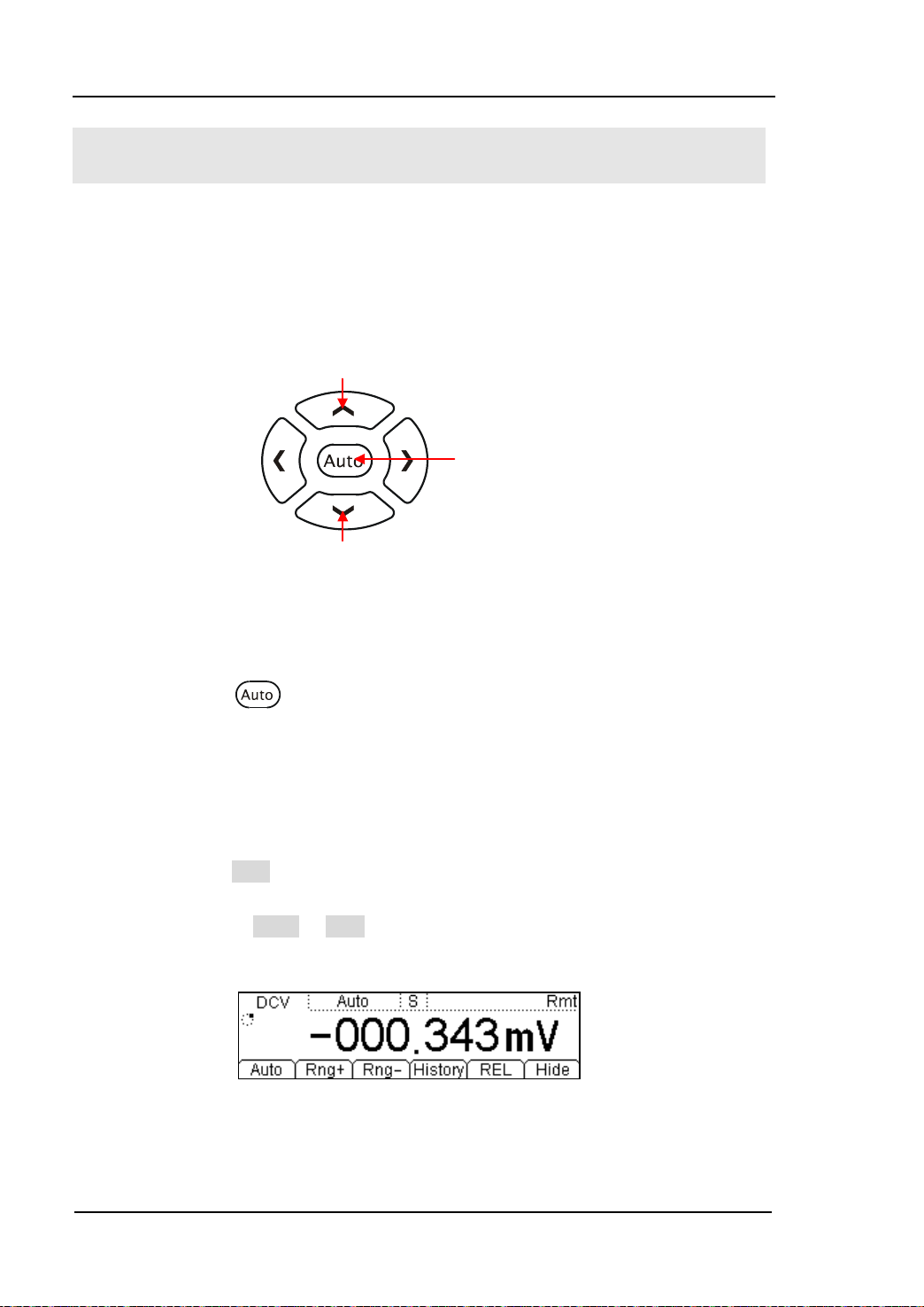
To Select Range
For the multimeter, appropriate range could be selected according to the signals
input by “Automatic” or “Manual”. In Manual mode, you can obtain higher reading
precision via range select keys on the right side of the Front Panel. See the figure
below.
Figure 2-1 Range selection keys
Method 1:
Via Function keys on the Front Panel
Increase range
Decrease range
Automatic range
Auto Range: Press
to choose Auto Range, meanwhile Manual Range is
forbidden.
Manual Range: Press Up or D o wn dir e ction keys to increase or decrease range
gradually, at this moment, Auto Rang e is forbidden.
Method 2:
Via soft keys on the M easurement main interface shown in Figure 2-2.
Auto Range: Press Auto to choose Auto Range, meanwhile Manual Range is
forbidden.
Manual Range: Press Rng+ or Rng- to choose required range manually, at this
moment, Aut o R a nge is forbidden.
Figure 2-2 Range selection menus
User’s Guide for DM3058/DM3058E
Page 25
RIGOL
2-3
NOTE
number will be selected, vice versa.
Explanations:
When the input signal is beyond the current sc ope of the measurement range,
the multimeter will show “OVER LOAD”.
After restarting and remote reset, range options will turn back to default
“Auto”.
You are suggested to select “Auto” range so as to protect the instrument
against damage and get ex ac t datum as much as possible when it is hard to
predict the range of measurement.
The range is fixed during testing the Continuity and Diodes. The range of
Continuity is selected as 2kΩ while the Diodes are 2.4V
.
Other functions of the d irection keys:
In the Save interface, Up and Down keys are used to select location for
the saving files.
During inputting data, Up and Down keys are used to change the
selected value. Each press for the up key, value will be increased 1,
vice ve rsa.
At the input interface of data, Left and Right keys are used to switch
the number of a numerical value. Each press for the Left key, former
User’s Guide for DM3058/DM3058E
Page 26

RIGOL
2-4
Reduce speed
Improve
To Select Measurement Rate
The instrument provides three types of measurement rate: 2.5 reading/s, 20
reading/s and 123 reading/s.
2.5 reading/s belongs to “Slow” rate; the mark of St atus Bar is “S” and the rate of
refurbishing is 2.5Hz.
20 reading/s belongs to “Middle” rate, the mark of Status Bar is “M” and the rate of
refurbishing is 20Hz.
123 reading/s belongs to “Fast” rate, the mark of Status Bar is “F” and the rate of
refurbishing is 50Hz.
Measurement rate could be controlled by Lef t and Right direction k e y. Each press
for the Left key, one level will be increased for rate, vice versa.
speed
Figure 2-3 Rate selection keys
Explanations
1. Three reading rates are available fo r DCV, ACV, DCI, AC and OHM.
2. To set as linkage for both reading resolution and reading (measurement) rate.
2.5 reading/s belongs to 5.5 digit resolution.
Both 20 reading/s and 123 reading/s belong to 4.5 digit resolution.
The reading resolution of Sensor is fixed at 5.5 digit and both “M” a nd “S” rate
can be chosen.
The reading resolutions and measurement rat es of both Diode and Continuity
are fixed at 4.5 digit and “Fast” respectively.
The reading resolution and measurement rate of the Freq function are fixed at
5.5 digit and “Slow” respectively.
The reading resolution and measurement rate of the Cap func tion are fixed at
3.5 digit and “Slow” respectively.
User’s Guide for DM3058/DM3058E
Page 27

RIGOL
2-5
Basic Measurement Functions
DM3058/DM3058E contains following basic functions:
To Measure DC Voltage
To Measure AC Voltage
To Measure DC Current
To Measure AC Current
To Measure Resistance
To Measure Capacitance
To Test Continuity
To Check Diode
To Measure Frequency and Period
Any Sensor Measurement
User’s Guide for DM3058/DM3058E
Page 28
RIGOL
2-6
DC Voltage
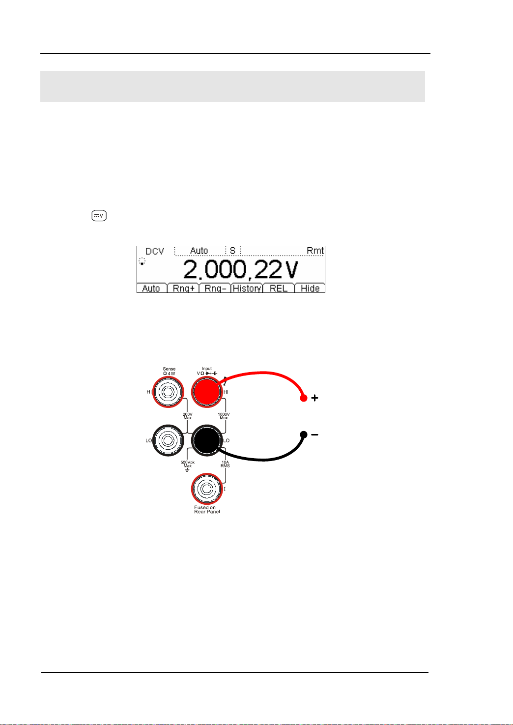
To Measure DC Voltage
The Multimeter enables to measure DC Voltage up to 1000V. For the details about
how to connect and measur e please refer to the following steps.
(NOTE: DC Voltage is always the selected function when the instrument
is turned on)
Operating Steps:
1. Press
interface.
2. Connect the red lead to terminal Inp ut-HI a nd b lack lead to terminal Input-LO
as the figure below.
on the Front Panel to enter into the DC Voltag e Measurement
Figure 2-4 DC Voltage Measurement Interface
Figure 2-5 Sketch map for connecting
User’s Guide for DM3058/DM3058E
Page 29
RIGOL
2-7
Configurable
3. Choose a proper Voltage range according to the measured circuit.
Table 2-1 Measurement Characteristics of DC Voltage
Ranges* 200mV, 2V, 20V, 200V, 1000V
Input Protection 1000V on all ranges (HI terminal)
Parameters
NOTE*: All the ranges enable to obtain 20% value higher than original except 1000V.
Besides, both Manual and Auto are available for setting every range. When inputting range
is higher than 1000V at 1000V Level, “OVER LOAD” will be shown on the screen. 1000V
input protection exists in every range.
Range, DC input impedance, REL
4. Set the DC input impedance
Press Res to set the DC resistance as “10 MΩ (default value)” or “>10
GΩ”. Users can execute DC voltage meas urement directly without modifying
this parameter which has been setup before leav ing factory.
5. Set relative value (Optional)
Press REL to open or close Relative math function. When it is open, “REL” is
shown over the screen and the reading displayed is a relative value which
comes from the result of actual measurement value subtracts the value that
has been set. (For the details about how to set, please refer to “
Math
Functions” in Chapter 2.)
6. Read measurement result
Select required measurement (reading) rate by using Left or Right direction
keys and read the measurement result.
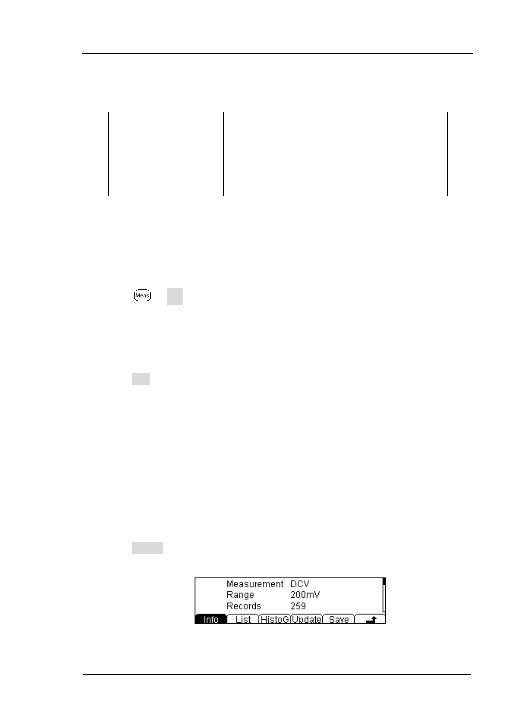
7. View history data
Press History to enter into the following interface and check the data getting
from this measurement and saved.
Figure 2-6 View interface of history data
User’s Guide for DM3058/DM3058E
Page 30

RIGOL
2-8
There are three ty p es of way for viewing historical date: “Info”, “List” and
“HistoG”. Press Save after checking, by pressing Update, the His tory
information will be refreshed to be current newest information.
User’s Guide for DM3058/DM3058E
Page 31

RIGOL
2-9
AC Vol
To Measure AC Voltage
The Multimeter enables to measure AC Voltage up to 750V. For the details about
how to connect and measur e please refer to the following steps.
Operating Steps:
1. Press
to enter into the AC Voltage Measurement interface.
Figure 2-7 AC Voltage Measurement Interface
2. Connect the red lead to terminal Input-HI and black lead to terminal Input-LO
as the figure below.
tage
Figure 2-8 Sketch map for connecting
3. Choose a proper Voltage range according to the measured circuit
Table 2-2 Measurement Characteristics of AC Vol t a ge
Ranges* 200mV, 2V, 20V, 200V, 750V
Input Protection 750Vrms on all ranges (HI terminal)
Configurable
Parameters
User’s Guide for DM3058/DM3058E
Range, REL
Page 32

RIGOL
2-10
NOTE*: All the ranges can obtain 20% value higher than original except 750V. Besides,
both Manual and Auto are available for setting every range. When inputting range is higher
than 750V at 750V Level, it will indicate “OVER LOAD”. 750Vrms input protection exists in
every range.
4. Set relative value (Optional)
Press REL to open or close Relative math functio n. When it is open, “REL” is
shown over the screen and the reading displayed is a relative value which
comes from the result of actual measurement value sub tracts the value that
has been set. (For the details about how to set, please refer to “
Math
Functions” in Chapter 2.)
5. Read measurement result
Select required measurement (reading) rate by using Left or Right direction
keys and read the measurement result. By this time, press and
get the frequency value measured from inputted AC signal.
Figure 2-9 Double display
6. View history data
Press History to enter into the following interface and check the data getting
from this measurement and save.
Figure 2-10
View interface of history information
There are three ty p es of way for viewing historical date: “Info”, “List” and
“HistoG”. Press Save after checking. By pressing Update, the History
information will be refreshed to be current newest in f or mation.
to
User’s Guide for DM3058/DM3058E
Page 33

RIGOL
2-11
DC Current
To Measure DC Current
The Multimeter enables to meas ure DC Current up to 10A. For the details about
how to connect and measur e please refer to the following steps.
Operating Steps:
1. Press
to enter into the DC Current Measurement interface.
Figure 2-11 DC Current Measurement Interface
2. Connect the red lead to terminal Input-I and black lead to terminal Input-LO as
the fi g ure below.
Figure 2-12 Sketc h map for conne cting
User’s Guide for DM3058/DM3058E
Page 34

RIGOL
2-12
Configurable
3. Choose a proper Current range according to the measured circuit.
Table 2-3 Measurement Cha r acteristics of DC Current
Ranges* 200μA, 2mA, 20mA, 200mA, 2A, 10A
Input Protection
Parameters
NOTE*: All the ranges enable to obtain 20% value higher than original except 10A.
Besides, both Manual and Auto are available for setting every range.
10A (Rear Panel)
12A (Inside the instrument)
Range, REL
4. Set relative value (Optional)
Press REL to open or close Relative math functio n. When it is open, “REL” is
shown over the screen and the reading displayed is a relative value which
comes from the result of actual measurement value sub tracts the value that
has been set. (For the details about how to set, please refer to “
Math
Functions” in Chapter 2.)
5. Read measurement result
Select required measurement (reading) rate by using Left or Right direction
keys and read the measurement result.
6. View history data
Press History to enter into the following interface and check the data getting
from this measurement and save.
Figure 2-13
View Interface of History Information
There are three ty p es of way for viewing historical d ate: “Info”, “List” and
“HistoG”. Press Save after checking. By pressing Update, the History
information will be refreshed to be current newest information.
User’s Guide for DM3058/DM3058E
Page 35

RIGOL
2-13
AC Current
To Measure AC Current
The Multimeter enables to measure AC Current up to 10A. For the details about
how to connect and measur e please refer to the following steps.
Operating Steps:
1. Press
to enter into AC Current Measurement interface.
Figure 2-14 AC Current Measurement Interface
2. Connect the red lead to terminal Input-I and black lead to terminal Input-LO as
the fi g ure below.
Figure 2-15 Sketc h map for conne cting
User’s Guide for DM3058/DM3058E
Page 36

RIGOL
2-14
Configurable
3. Choose a proper Current range according to the measured circuit
Table 2-4 Measurement Characteristics of AC Current
Ranges* 20mA, 200mA, 2A, 10A
Input Protection
Parameters
NOTE*: All the ranges enable to obtain 20% value higher than original except 10A.
Besides, both Manual and Auto are available for setting every range.
10A(Rear Panel), 250V(Fuse), 12A(Inside the
instrument)
Range, REL
4. Set relative value (Optional)
Press REL to open or close Relative math functio n. When it is open, “REL” is
shown over the screen and the reading displayed is a relative value which
comes from the result of actual measurement value subtracts the value that
has been set. (For the details about how to set, please refer to “
Math
Functions” in Chapter 2.)
5. Read the measurement result
Select required measurement (reading) rate by using Left or Right direction
keys and read the measurement result.
6. View history data
Press History to enter into the following interface to check the data getting
from this measurement and save.
Figure 2-16 View interface of history information
There are three ty p es of way for viewing historical d ate: “Info”, “List” and
“HistoG”. Press Save after checking, by pressing Update, the History
information will be refreshed to be current newest in f or mation.
User’s Guide for DM3058/DM3058E
Page 37

RIGOL
2-15
Res
I
To Measure Resistance
The multimeter provides 2-wire and 4-wire resistance measurement modes which
are introduced separately in the following part.
2-Wire Resistance Measurement
Operating Steps:
1. Press
interface.
2. Connect the red lead to terminal Input-HI and black lead to terminal Input-LO
as the f igure below.
and select 2-Wire Resistance Measurement Mode to enter following
Figure 2-17 2-Wire Resistance Measurement Interface
istance
Figure 2-18 Sketc h map for conne cting
User’s Guide for DM3058/DM3058E
Page 38

RIGOL
2-16
3. Choose a proper Resistance rang e according to its scop e.
Table 2-5 Measurement Characteristics of Resistance
Ranges*
200Ω, 2kΩ, 20kΩ, 200kΩ, 2MΩ, 10MΩ,
100MΩ
Open-circuit Voltage <8V
Input Protection
Configurable
Parameters
NOTE*: All the ranges enable to obtain 20% ranges higher than original. Besides, both
Manual and Auto are available for setting every range.
1000V on every range (HI
Range, REL
terminal)
4. Set relative value (Optional)
Press REL to open or close Relative math functio n. When it is open, “REL” is
shown over the screen and the reading displayed is a relative value which
comes from the result of actual measurement value sub tracts the value that
has been set. (For the details about how to set, please refer to “
Math
Functions” in Chapter 2.)
5. Read the measurement result
Select required measurement (reading) rate by using Left or Right direc tion
keys and read the measurement result.
6. View history data
Press History to enter into the following interface to check the data getting
from this measurement and save.
Figure 2-19 View interface of history information
There are three ty p es of way for viewing historical date: “Info”, “List” and
“HistoG”. Press Save after checking, by pressing Update, the History
information will be refreshed to be current newest in f or mation.
User’s Guide for DM3058/DM3058E
Page 39

RIGOL
2-17
I
Resistance
4
4
NOTE
You are suggested to make use of Relative function when measuring
small resistance to reduce or escape impedance error from Test leads.
4-Wire Resistance Measurement
When the measured resistanc e is smaller than 100kΩ, if both the resistance of Test
leads and the contact resistance between probe and testing point ar e too big to be
ignored as comparing with measured resistance, the error will be increased
provided that you insist on measuring by via 2-Wire Resistance. So please chang e it
to 4-Wire.
Operating Steps:
1. Press
twice to switch to 4-Wire Resistance Mode.
Figure 2-20 Measurement Interface
2. Connect the red leads to terminal Input-HI and HI Sense and black leads to
terminal Input-LO and LO Sense as the figure below.
-Wire Sense HI
-Wire Sense LO
Figure 2-21 Sketc h map for conne cting
User’s Guide for DM3058/DM3058E
Page 40

RIGOL
2-18
(1) 1000V on each range (HI terminal)
Configurable
3. Choose an appropriate resistance range ac cording to its scope.
Table 2-6 Measu reme nt Char acteristics of 4-Wire Resistance
Ranges* 200Ω, 2kΩ, 20kΩ, 200kΩ, 2MΩ, 10MΩ, 100MΩ
Open-circuit
Voltage
Import Prote ction
Parameters
NOTE*: All the ranges enable to obtain 20% ranges higher than original. Besides, both
Manual and Auto are available for setting every range.
<8V
(2) 200V on each range (HI Sense, LO Sense)
Range, REL
4. Set relative value (Optional)
Press REL to open or close Relative math functio n. When it is open, “REL” is
shown over the screen and the reading displayed is a relative value which
comes from the result of actual measurement value sub tracts the value that
has been set. (For the details about how to set, please refer to “
Math
Functions” in Chapter 2.)
5. Read the measurement result
Select required measurement (reading) rate by using Left or Right direction
keys and read the measurement result.
6. View history data
Press History to enter into the following interface and check the data getting
from this measurement and save.
Figure 2-22 History Information
There are three ty p es of way for viewing historical d ate: “Info”, “List” and
“HistoG”. Press Save after checking. By pressing Update, the History
information will be refreshed to be current newest information.
User’s Guide for DM3058/DM3058E
Page 41

RIGOL
2-19
NOTE
Please do not put the terminals of the resistance on the conductive
plane or in your hand to avoid error.
The bigger of the resistance, the more affection it will be brought.
User’s Guide for DM3058/DM3058E
Page 42

RIGOL
2-20
Capacitance
To Measure Capacitance
The DM3058/DM3058E Digital Multimeter has the ability to test Capacitance up to
10000μF.
Following practice provides you a guide to get familiar with the Capacitance
measurement technique.
Operating Steps:
1. Press
to enter into Capacitance measur ement interface.
Figure 2-23
Capacitance Measurement Interface
2. Connect red lead to both terminal Input-HI and anode of the capacitance and
black lead to both terminal Input-LO and cathode of the c apac itance a s t he
figure below.
Figure 2-24 Sketc h map for conne cting
User’s Guide for DM3058/DM3058E
Page 43

RIGOL
2-21
Configurable
3. Choose an appropriate measurement range according to its scope.
Table 2-7 Capacitance Measurement Characteristics
Ranges* 2nF, 20nF, 200nF, 2μF, 200μF, 10000μF
Input Protection 1000V on all ranges (HI terminal)
Parameters
NOTE*: All the ranges enable to obtain 20% ranges higher than original. Besides, both
Manual and Auto are available for setting every range.
Range, REL
4. Set relative value (Optional)
Press REL to open or close Relative math functio n. When it is open, “REL” is
shown over the screen and the reading displayed is a relative value which
comes from the result of actual measurement value sub tracts the value that
has been set. (For the details about how to set, please refer to “
Math
Functions” in Chapter 2.)
7. Read the measurement result
Capacitance measurement is fixed at “Slow” rate, 3.5 digits resolution.
Therefore , you cannot adjust the reading rate when reading the result.
5. View history data
Press History to enter into the following interface and check the data getting
from this measurement and save.
Figure 2-25 View interface of History information
There are three ty p es of way for viewing historical date: “Info”, “List” and
“HistoG”. Press Save after checking. By pressing Update, the History
information will be refreshed to be current newest in f or mation.
NOTE
Before measuring the electrolytic capacitance, you should make the two
legs of the electrolytic capacitance short circuit and let it be discharged.
User’s Guide for DM3058/DM3058E
Page 44

RIGOL
2-22
I
To Test Continuity
When the measured resistanc e in circuit is lower than selected one, it is considered
being connected by instrument. Nex t, we will introduce you how to test continuity
for circuit by using DM3058/DM3058E step by step to make y ou familiar with this
technique.
Operating Steps:
1. Press
2. Connect test leads as the figure below. Red lead connects with HI terminal;
Black lead connects with LO terminal.
to enter into the following interface.
Figure 2-26 Continuity Testing Interface
Open or Closed Circuit
Figure 2-27 Sketch map for testing
3. Set the Short-circuit resistance.
Press Set to set up the resistance of short-circuit. The default value is set as
10Ω when leaving factory. U sers may carry on the Continuity measurement
directly without modification.
User’s Guide for DM3058/DM3058E
Page 45

RIGOL
2-23
Table 2-8 Continuity Measurement Characteristics
Test Current 1mA
Range Fixed at 2kΩ
Open-circuit Voltage <8V
Input Protection 1000V (HI terminal)
Beep Condition
0≤R
≤Short-circuit impedance;
testing
1Ω≤Short-circuit impedance≤2kΩ
User’s Guide for DM3058/DM3058E
Page 46

RIGOL
2-24
Forward Bias
I
To Check Diode
Operating Steps:
1. Press
to enter into the following interface.
Figure 2-28 Testing interface of Diode
2. Connect red lead to both terminal Input-HI and anode of the Diode and black
lead to both terminal Input-LO and cathode of the Diode as the figure below.
Figure 2-29 Sketc h map for conne cting
3. Check the connection state of Diode.
When connecting, the instrument will beep one time (If Sound is open).
Table 2-9 Check Diodes Characteristics
Test Current 1mA
Range Fixed at 2.0V
Open-circuit Voltage <8V
Input Protection 1000V (HI terminal)
Beep Condition 0.1V≤V
measured
≤2.0V
User’s Guide for DM3058/DM3058E
Page 47

RIGOL
2-25
AC Signal
To Measure Frequency and Period
The Frequency or Period of a signal could be obtained by Secondary F unction
during testing its voltage or current or by function button
practice provides a guide to get familiar with the Frequency and Period
measurement.
. The following
To Measure Frequency
Operating Steps:
1. Press
2. Connect test leads as the figure below. Red test lead connects with terminal
HI; Black test lead connects with terminal LO.
to enter into the following interface.
Figure 2-30 Frequency Measurement Interface
Figure 2-31 Sketc h map for conne cting
User’s Guide for DM3058/DM3058E
Page 48

RIGOL
2-26
Table 2-10 Frequency Test Characteristics
Ranges 200mV, 2V, 20V, 200V, 750V
Input Signal Range 20Hz ~ 1MHz
Input Protection 750VRMS on all ranges (HI terminal)
Configurable Parameters REL
3. Set the relative value (Optional).
Press REL to open or close Relative operation function. When it is open, “REL”
is shown over the screen and the reading displayed is a r elative value which
comes from the result of Actual measurement value subtracts the value that
has been set. (For the details about how to set, please refer to “
Math
Functions” in Chapter 2.)
4. Read measurement value
Frequency measurement is f ixed at “Slow” rate, 5.5 digits resolution. Therefore,
you cannot adjust the reading rate when readin g the result .
5. View history data
Press History to enter into the following inter face and check the data getting
from this measurement and saved.
Figure 2-32 View interface of History information
There are three ty p es of way for viewing historical d ate: “Info”, “List” and
“HistoG”. Press Save after checking. By pressing Update, the History
information will be refreshed to be current newest in f or mati on.
User’s Guide for DM3058/DM3058E
Page 49

RIGOL
2-27
AC Signal
To Measure Period
Operating Steps:
1. Press
until enter into the following interface.
Figure 2-33 Period Measurement Interface
2. Connect the red lead to terminal-HI and black lead to terminal LO as the figure
below.
Figure 2-34 Sketc h map for conne cting
Table 2-11 Period Characteristic
Ranges 200mV, 2V, 20V, 200V, 750V
Measurement Range
1μs~0.05s
Input Protection 750VRMS (HI)
Configurable Parameters REL
User’s Guide for DM3058/DM3058E
Page 50

RIGOL
2-28
3. Set the relative value (Optional)
Press REL to open or close Relative operation function. When it is open, “REL”
is shown over the screen and the reading displayed is a r elative value which
comes from the result of Actual measurement value subtracts the value that
has been set. (For the details about how to set, please refer to “
Math
Functions” in Chapter 2.)
4. Read the measurement value
Period measurement is fixed at “Slow” rate, 5.5 digits resolution. Therefore,
you cannot adjust the reading rate when readin g the result.
5. View history data
Press History to enter into the following interface and check the data getting
from this measurement and save.
Figure 2-35
View Interface of History Informati on
There are three ty p es of way for viewing historical d ate: “Info”, “List” and
“HistoG”. Press Save after checking. By pressing Update, the Histor y
information will be refreshed to be current newest in f or mation.
User’s Guide for DM3058/DM3058E
Page 51

RIGOL
2-29
Any Sensor Measurement
By using any sensor measurement, you can connect Pressure Sensor, Flux Sensor
or Temperature Sensor easily. Its principle is that transmit measured physical
quantity to a facile measured one such as Voltage, Resistance and Current by these
steps. First, pre-input the needed data; secondly, transform or modify it according
to the interior arithmetic of Multimeter. Afterward, a measured physical quantity of
Sensor is shown on the screen directly and you can edit or modify its display unit at
will.
The multimeter suppo rt s DCV, DCI, and Freq, 2WR , 4WR and Thermocouple TC 6
kinds of Sensor in all. Meanwhile, there are 10 groups of basic Sensor preset within
the instrument.
User’s Guide for DM3058/DM3058E
Page 52

RIGOL
2-30
Connection
Different Sensor has different connecting ways. As the Voltage Sensor, Resistance
Sensor, Thermocouple S ensor and Frequency Sensor, please Connect the red lead
to terminal Input-HI and black le a d to terminal Input-LO as t he figure below.
Sensor
Figure 2-36 Sketc h map for conne cting
As the Current Sensor, please connect the red lead to terminal Input-I and black
lead to terminal Input-LO as the figure below.
Sensor
Figure 2-37 Current Sensor Connecting
User’s Guide for DM3058/DM3058E
Page 53

RIGOL
2-31
Basic measurement method
Press to enter into the following interface.
Figure 2-38
Measurement Interface of Sensor
Table 2-12 Chara cteristics of Sensor
Function Description
New Built a new configuration file of Sensor
Edit Edit an existing configuration file
Load Load an existing conf iguration file
History Check newest 1000 measurement datum
REL Open/Close Relative Operati on
Disp Set sensor measurement display mode
1. Press New to create a new Sensor.
Figure 2-39 New in t erface
(1) Press Prpty to enter into the input interface.
Figure 2-40 Property Interface
User’s Guide for DM3058/DM3058E
Page 54

RIGOL
2-32
Press Name to create an appropriate name for the new sensor.
File Name
Input Area
Figure 2-41 Name edit interface
File Name Input Method:
Use the up/down direction keys to select the File Name or Input Area.
Use the left/right direction keys to move the cur sor to the position (File Name
Area) or charact e r (I npu t Area).
Press A, a and 1 to select the Capital letter, Lowerc ase letter or Numbers.
The Del function can only delete the letter on which the cursor taking place.
Press Done to save current file.
Press to return to the Prpty interface.
Press Type to select the type of easy-to-measure physical quantity (DCV, DCI,
2WR, 4WR, FREQ and TC). Press the corresponding menu to select the type
and then, press to return to the Prpty interface.
Figure 2-42 Type selection interface
Press Unit button to select the unit (°, °C, °F and %) for the measured
physical quantity. Furthermore, you can define a desired unit using the USER
function.
Figure 2-43 Unit selection interface
Explanations:
User-defined unit is limited within two characters.
Switch to the charac ter which needs to be edited by the left/right direction keys.
Select required charac ter s by the up/down direction keys from A-Z and a-z.
User’s Guide for DM3058/DM3058E
Page 55

RIGOL
2-33
Arithmetic of
Incept
Press to return to the New interface and do next steps.
(2) Press Define to input corresponding data. Different kind of Sensor has different
relationship of corresponding data. It is not nec essary to input plenty reference
value if the corresponding relationship has more smoothness and good
linearity curve. Then press Add to input reference data.
Press Meas to input the data measured from Sensor by Direction keys.
Figure 2-44 Input data
Press Corrsp to input the corresponding data by Direction keys.
Figure 2-45 Input data
Press Done to finish the input for first group of data and go back to View
Interface of Reference valu e. Please pay attention that
indicates the
approximate arithmetic of d atum between this data and next one. The
arithmetic of first data sect is default as “Line” which can be modif ied by
clicking Edit.
symbol
current data
Figure 2-46 View interface of Reference data
Repress Add to input second group of data. From this group you can press
SEG “Open” Arith and select arithmetic.
User’s Guide for DM3058/DM3058E
Page 56

RIGOL
2-34
Figure 2-47 On/Off section interface of Arithmetic
Press to finish the parameter settings and return to the New interface
(figure 2-39).
(3) Press Done (figure 2-39), it will appear Save and Apply options.
Figure 2-48 Finishing interface
Press Save and i nput needed File Name.
Figure 2-49 Finishing interface
Press Done and store the parameter of Sensor as appointed name for future
using.
Figure 2-50 Save Interface
Press and return to the New interface.
Press Apply as sho wn in figure 2-48 and load settings into current Sensor and
use it directly.
User’s Guide for DM3058/DM3058E
Page 57

RIGOL
2-35
Figure 2-51 Apply new Sensor
After application, the data app earing in the interface is unavailable by “
”.
2. If you found there are som e problems existing please press Edit to modify.
Figure 2-52 Edit configuration file of Sensor
3. Press Load to recall configuration file within Sensor.
4. Press History to enter into the following interface to check the data getting
from this measurement and save.
Figure 2-53 View interface of History Information
There are three types of way for viewing historical date: “Info” and “List”.
Press Save after checking, by pressing Update, the History information will be
refreshed to be current newest information.
5. Set relative value (optional)
Press REL to open or close Relative operation. When it is open, “REL” is shown
over the screen and the reading displayed is a relative value which comes from
the result of actual measurement value subtracts the value that has been set.
(For the details about how to set, please refer to “
Math Functions” in
Chapte r 2.)
6. Press Disp to set the display mode for the measurement result: only display
the measured result (select Meas); only display the corresponding result
(select Corrsp); when All is selected, the measured result will be shown on the
Vice display and the corresponding result will be shown on the Main displa y.
User’s Guide for DM3058/DM3058E
Page 58

RIGOL
2-36
Figure 2-54 Display mode
Figure 2-55 Display the value
User’s Guide for DM3058/DM3058E
Page 59

RIGOL
2-37
Preset
Preset mode is provided to avoid error operation via testing produc t line. In any
operatio n mode, please press to enter into following menu.
Figure 2-56 Interface of Preset
Ten sets existing in preset mode and all of them are corresponding with the 10
conf iguration files in configuration memorizer respectively.
Press Setn (n=1~10) to recall the corresponding settings and exit Preset menu.
Explanations:
A click will be emitted by instrument after you press any preset configuration
key if an effective configuration is existing in its Location of corresponding key,
meanwhile, current measurement configuration will be refreshed to the one
has be en stored. If th e selective configuration location is empty, the
instrument will emit “click pause click” and then go back to primary
testing state.
Press Setn, current measurement configuration would be
saved into corresponding location and named “Setn” as a d efault.
Besides, you can also recall or save preset configuration by using
function.
User’s Guide for DM3058/DM3058E
Page 60

RIGOL
2-38
Main Display Function
DCV
DCI
ACV
ACI
FREQ
PERIOD
2WR
4WR
Cap
DCV
DCI
ACV
ACI
FREQ
PERIOD
2WR
4WR
Cap
Secondary Function
Secondary funct i on button is used to open double display, save current
instrument settings and op en the REL setting interface quickly.
1. Open Double Display
Press , this button will shine and the instrument is going to wait for the
secondary operation. By this time, if you press a function ke y, it will be
displayed in the Vice Display (for available combination, see table 2-13).
Table 2-13 Available Main/Vice Function Combination (shade is available)
Vice
Display
Function
Explanations:
(1) If the same measurement function is used in both Main and Vice Display
The readings in both of the display will update at the same time.
If Math function (STA, REL, dBm and dB) is used in Main Disp lay, when
opening Vice Display, the result will be shown in Main Display and the
measurement value before math operation is shown in Vice Disp lay.
If Math function (P/F) is used in Main Display, when open V ice Display, P/F
operation will be closed automatically and Vice Display will show the second
selected function normally.
(2) If different measurement functions are used in both Main and Vice Display
The readings in both of the display will update alternately.
If Math function (STA, P/F, dBm and dB) is used in Main Display, when open
User’s Guide for DM3058/DM3058E
Page 61

RIGOL
2-39
Vice Display, math operation will be closed automatically and Vice Display will
show the second selected function normally.
If Math function (REL) is used in Main Display, when op en Vice Display, the
result will still be shown in M ain Display and Vice Display will show the second
selected function normally.
(3) If Sensor is used in Main Display, set the display mode ( Disp All), then
the result (corresponding value) will be shown in Main Display and the current
measurement value is shown in Vice Display.
(4) Auto Range is adopted by Vice Display. If the same measurement function is
used in both the display, so does the ra nge.
(5) Measured data in Vice Display cannot be saved into “History”.
2. Save Current Settings Quickly
Press , and then press any Setn key, the instrument will store
current instrument settings to correspondin g mem or y with default filename
“Setn”. You can also finish this operation through the
function (see the
Store and Recall section).
3. Open REL Settings Interface Quickly
In general measurement interface, press , then press the REL menu to
enter
Figure 2-65 Relative operation setting interface immediately.
User’s Guide for DM3058/DM3058E
Page 62

RIGOL
2-40
NOTE
To Control Trigger Options
or could be used to trigger the multimeter. Auto trigger is considered as
a default when the po wer is on. Then
this function has been started.
Optional trigger modes of the multimeter contain Auto Trigger, Single Trigger and
Hold Trigger.
Auto Trigger
Once you press
readings automatically.
Single Trigger
Press
generate an effective reading.
Holding Trigger
Press
display.
on the Front Panel, Single Tr igger will be started one time and
key, it allows capturing and holding a stable reading on the front panel
Press in Remote Mode to switch back to the local mode.
one time, Auto Trigger will be started to captur e continuous
key will be lightening which indicates
User’s Guide for DM3058/DM3058E
Page 63

RIGOL
2-41
To Set up Measurement Parameters
Press to set measurement parameters for DC Voltage, DC Curr en t and
Continuity.
The parameters have been configured when the multimeter leaving factory. So you
can either measure directly or modify them to meet your requirements.
AC Filter
AC Filter is applicable for DC Voltage and DC Current measurement.
While either DC Voltage or DC Current function is selected, press Filter,
enter the menu shown belo w. If AC component existing in inputted DC signal, it
can be f il tered by AC Filter so as to make the data more exactly.
Figure 2-57 Open/Close AC Filter
User’s Guide for DM3058/DM3058E
Page 64

RIGOL
2-42
DC input impedance selection:
of
200mV and 2V measurement range is >10GΩ; for 20V, 200V and 1000V
MΩ; settings of DC input impedance
DC Input Impedance
DC input impedance is applicable for DC voltage measurement.
Press Res enter the menu shown below when select DC voltage measure
function.
Figure 2-58 Choose DC Impe da nce
Table 2-14 DC In pu t Impedance Menu Description
Function Menu Description
10MΩ Set up the DC Input Impedance to 10MΩ.
>10GΩ Set up the DC Input Impedance to >10GΩ.
The options of input impedance for DC voltage measurements are 10MΩ
and >10GΩ. 10MΩimpedance is general for the multimeter, but for 200mV and 2V
ranges, >10GΩ should be chosen for better result. The current selection will be
saved in nonvolatile memory.
While the DC input impedance is selected to 10MΩ, the input impedance
all measurement range is 10MΩ;
While the DC input impedance is selected to >10GΩ, the input impedance
for
measurement range is kept at 10MΩ.
The DC input impedance default is 10
are stored in the nonvolatile memory.
Save all changes, back to a higher level m enu.
User’s Guide for DM3058/DM3058E
Page 65

RIGOL
2-43
Continue Resistance
Short-circuit Resistance
Set up the short-circuit resistance value in the short-circuit test menu. When the
measured resistance is lower than the short-circuit resistance, the circuit is
considered as connected, and the beeper sounds (if sound is on). The
short-circuit resistance is only applicable to the continuity test.
Press Conti, enter the menu shown below:
Figure 2-59 Set up the short-circuit resistance
Use direction keys to change the parameter values:
Press left and right direc tional keys to choose different digits. Press up and down
keys to change the c urrent digit value.
The range of short-circuit resistance is 1Ω~2000Ω. The default value is
The short-circuit resistance value is stored in the nonvolatile memory and
User’s Guide for DM3058/DM3058E
10Ω.
the resistance remains unchanged after power-off.
Page 66

RIGOL
2-44
Function
Menu
Reading statistic functions, including: Max, Min,
The P/F test function perfor ms pass/fail testing
The dBm function is logarithmic, and is based
on a calculation of power delivered to refer ence
impedance.
Math Functions
The multimeter provides five math functions: STA, P/F, dBm, dB and REL testing.
Math functions can only be used in DC voltage, AC voltage, DC current, AC current,
resistance, frequency/period and sensor measurement. Among the functions, dBm
and dB are only used in DC voltage and AC voltage measurement.
Press
key, the display shows:
Voltage Measurement
Current, Resistance, Frequency/Period
Capacitance and Sensor measurement
Figure 2-60 Math function
Table 2-15 Math Function Menu Description
Settings Description
STA
Average, and number of measurement.
P/F
according to the specified upper and lower
limits.
dBm
dB
REL
ON
OFF
The dB measurement is the difference between
the input signal and a stored relative value.
Turn on /Turn off the REL f unction.
Save all changes, back to a higher level m enu.
User’s Guide for DM3058/DM3058E
Page 67

RIGOL
2-45
To show the maximum statistic value of curre
To show all statistic values
ON
Turn on/off the selected statistic
Save all changes, back to a higher level
Statistic function
Statistic Measurement
The Statistic function is for DC voltage, AC voltage, DC current, AC current,
resistance, frequency/period, capacitance and sensor measurement.
The front panel can display the statistical data for any set of readings: average
(AVG), maximum (MAX), minimum (MIN), and which can read with All functions
and the number of samples taken (Total).
Press STA, the display shows:
Figure 2-61 Stat. Math
Table 2-16 Statistic Measurement Menu Function Description
Function Menu Settings Description
MAX
MIN
AVG
All
ON
OFF
nt measurement
To show the minimum statistic value of curre
nt measurement
To show the average statistic value of current
measurement
of current measurement
measurement
menu.
In statistic function, the first reading is usually set to the maximum or
minimum value. When getting more readings, current displaying value is
always the maximum/minimum reading among all the measured values.
The maximum, minimum, average and reading quantities are stored in
volatile memory.
User’s Guide for DM3058/DM3058E
Page 68

RIGOL
2-46
P/F Measurement
P/F function is available to prompt signals beyond ranges according to the upper
and lower parameters. Following are some measurement functions which are able
to do limit operation: DC Voltage, AC Voltage, DC current, AC current, Resistance,
Frequency, Capacitance and Sensor.
Press P/F, the display shows:
Figure 2-62 P/F Setting
Table 2-17 P/F Measurement Menu Function Description
Function Menu Settings Description
High Set the desired U pper limit.
Low Set the desired Lower limit.
ON
1. Set P/F
Select High or Low, and then switch to the needed digit by Left or Right
Direction key s and input numerical value by Up and Down Direction keys. Use
Left key to pitch on symbol on the left side when setting Positive or Negative
and switch them by Up and Down Direction keys.
2. Unit
The unit of P/F is decided by the current measurement function.
3. Over P/F hint
When the readings exceed selected upper limit, the vice -scream will show “HI
FAIL”.
Open P/F Measurement, Status bar shows
“P/F”.
Save all changes, back to a higher level
menu.
User’s Guide for DM3058/DM3058E
Page 69

RIGOL
2-47
The range of P/F function:
When the readings exceed selected lower limit, the Vice display will show “LO
FAIL.
When the readings exceed either upper or lower limit, an alarm will be given
(when the sound is open).
The P/F range is -120%~+120% of the current measurement range.
The upper limit value should be always bigger than the lower limit value.
The upper and lower values are stored in volatile memory. They will be set
to defaults when powe r on.
User’s Guide for DM3058/DM3058E
Page 70

RIGOL
2-48
dBm Measurement
This function applies to AC voltage and DC voltage measurements only.
The dBm function is logarithmic, and is b ased on a calculation of power delivered to
a reference resistance, relative to 1 mill watt.
Press dBm, the display shows:
Figure 2-63 dBm setting
Table 2-18 dB Measurement Function Menu Fun ctio n Desc ription
Function Menu Settings Description
Default
ON
The computation method of the dBm:
Use the default value. The range o f
parameter is 2Ω ~ 8000Ω.
Open dBm Measurement.
Status bar shows “dBm ”.
Save all changes, back to a higher level
menu.
dBm = 10 x Log
[(Reading2 / R
10
) / 0.001W ]
REF
User’s Guide for DM3058/DM3058E
Page 71

RIGOL
2-49
Open dB Measurement.
Status bar sh ows “dB”.
Save all changes, back to a higher level
NOTE:
dB Measurement
The dB function applies to AC voltage and DC voltage measurements only.
Each dB measurement is d iffer ent between the input signal and a stored relative
value, with both values converted to dBm.
Press dB, enter the menu shown below:
Figure 2-64 dB Setting
Table 2-19 dB Measurement Function Menu Fun ctio n Desc ription
Function Menu Settings Description
Default The default value is 0 dBm.
ON
menu.
The computation method of the dB:
dB =10xLog
[(Reading2 / R
10
) / 0.001W] – (dB setting value)
REF
R
expressed measuring the r esistance value in the actual electric circuit.
REF
Range of the dB setting v alue : -120 dB m ~ +120 dBm. The default is 0 dBm.
Input a value in dB setting interface by direction b utton, and then store
it as dB setting value.
Settings of dB value are sto red in volatile memory.
User’s Guide for DM3058/DM3058E
Page 72

RIGOL
2-50
To select current measurement value as
Set preset value
on the operating inter face directly to enter into the
Relative Operation
Relative operation is used for relative measurement. Actual measurement reading is
the depression between measurement value and preset value.
Press REL to enter into the following interface.
Figure 2-65 Relative operation setting interface
Table 2-20 REL operation function menu
Function Menu Settings Explanation
Current
preset value.
Clear Reposition the preset value to 0.
On/Off
Open/Close this function. When opening,
“REL” will be shown.
Save all the changes and go back to last
menu.
Main display = Measurement value –preset value
The Multimeter allows operating for following parameters: DC Voltage, AC Voltage,
DC Current, AC Current, Resistance, Freq uency/Period, Capacitance and Sensor.
Press REL
“Preset Value” setting interface.
Select Current, press On/Off to start REL operation, and then the
readings in current set will be stored as a reference value.
Users can input needed preset value by direction keys in the
corresponding setting interface.
User’s Guide for DM3058/DM3058E
Page 73

RIGOL
2-51
Set interval of the auto tr igger and hold range
continuous in auto trigger mode.
To Set Up Trigger Parameters
The optional Trigger methods of the multimeter include Auto Trigger, Single Trigger
and External Trigger. The default trigger mode is Auto.
Press
more, a stable reading will be captured and hold .
Press
captured.
Press
Parameter setting, after you select Auto, Singe, Ext or VMC on the menu, the
current trigger mode shown in the parameter area will be changed accordingly and
display relative parameter for current trigger.
Table 2-21 Function Menu o f t riggeri ng parameter
Function Menu Settings Description
to capture continuous readings automatically. If you repress it once
, Single Trigger will be generated on time, and an effective reading will be
to set parameters for every trigger. In the following interface of
Figure 2-66 Interface of triggering parameter
Auto
Single
Ext
VMC
User’s Guide for DM3058/DM3058E
of the hold trigger. Besides, the measu rement is
Set Single manual trigger parameter.
Set external triggering.
Set the output signal pulse width at sampling
ending output signal.
Save all changes, back to a higher level m enu.
Page 74

RIGOL
2-52
urn the Reading Hold function ON or
es, back to a higher level
Auto Triggering
“Interval” parameter needs to be set in auto trigger mode. Press
panel to enable the auto trigger and acquire continue readings. Furthermore, auto
trigger is the default mode at digital multimeter power on.
Press Auto, the display shows:
Figure 2-67 Setting interface of Auto Trigger
Table 2-22 Auto Trigger Function Menu Description
Function Menu Settings Description
on the front
Interval Set interval time in 400~2000ms.
Hold ON/OFF
T
OFF.
Save all chang
menu.
1. Interval
The interval means the waiting time before sampling since trigger signal has
been sent. The interval is differ ent under different measure speed.
Fast: the default interval is 8ms, setting rang e is 8ms~2000ms.
Middle: the default interval is 50ms, setting range is 50ms~2000ms.
Slow: the default interval is 400ms, setting rang e is 400ms~2000ms.
The default measure speed is slow, so the default interval is 400ms.
The interval is stored in volatile memory.
2. Reading Hold
The reading hold mode captures and holds a read ing on the front panel display
when a stable reading is detected. The system Hold ranges are 0.01%, 0.1%,
1%, and 10%.
User’s Guide for DM3058/DM3058E
Page 75

RIGOL
2-53
Save all changes, back to a higher level
menu.
NOTE:
testing.
Press two times until this button is glittery, then a trigger will be hold and
a stable reading will be c aptured and hold on the screen.
Press Auto Hold, the display shows:
Figure 2-68 Manu interface of Reading Hold
Table 2-23 Readin g Hold F unction Menu Description
Function Menu Settings Description
On/Off
0.01%
0.1%
1%
10%
Turn on/off the reading hold function.
Set the hold scope as 0.01%.
Set the hold scope as 0.1%.
Set the hold scope as 1%.
Set the hold scope as 10%.
Reading Hold Function
Start the Reading Hold Function, the hold measurement use the following rules
judge the reading count:
When Max () - Min () ≤ hold range x Readings, the multimeter hold Reading on the
display.
The display update a new r eading basing on the current value and the three
preceding measurements before the reading was hold:
Max (Reading, ReadingN-1, ReadingN-2, ReadingN-3)
Min (Reading, ReadingN-1, ReadingN-2 , Re adingN-3)
The default value of hold r ang e is 0.1%, and the range setting is
stored in volatile memory.
When Reading Hold started, the input resistance was set to 10MΩ for
all DC voltage ranges to reduce noise arising from the open-loop
User’s Guide for DM3058/DM3058E
Page 76

RIGOL
2-54
Sample Count
Single Triggering
The multimeter takes one reading , or a number of readings specified by a sample
count you enter, each time press
Press Single to enter into the following interface. Then Input needed sample
counts by Direction keys. After setting please press Done to open Single Trigger, at
this time Done is hiding and is lighten.
Figure 2-69 Settings of sample count
Sample Count indicates the count of point sampled while the instrument
getting a signal of Single Trigger.
The range of sampling point should be between 1 and 2000.
The default of Sample Count is 1.
.
User’s Guide for DM3058/DM3058E
Page 77

RIGOL
2-55
Function Menu
Settings
Explanation
Set the External Trigger Mode as Rising
Set the External Trigger Mode as
External Triggering
The external trigger signal will be input via the ninth pin of RS232 interface on the
rear panel. It requires setting the following parameter: the Rise edge and the Fall
edge.
Press Ext, the display shows:
Figure 2-70 The Interface of the Exter nal Triggering
Table 2-24 Function Menu of External Triggering
Rise
Fall
Edge.
Falling Edge.
Save all the changes and go back to
last menu.
1. To run External Trigger
After setting the parameter, press
to go back to last Manu and run
External Trigger by press ing Done. Now, and on the Front Panel will
be crushed out, the instrument enter into the External Trigger Mode.
2. To set Output
In External Trigger Mode, the instrument co uld output a pulse signal through
the six pin of RS232 interface on the rear panel after finishing sampling data.
By the way, the polarity and output pulse width of this signal could be
adjusted.
User’s Guide for DM3058/DM3058E
Page 78

RIGOL
2-56
The VMC function output
Press VMC, the display shows:
Figure 2-71 Set Output Pulse
Table 2-25 The Explanation of the External Triggering
Function Menu
Polar
Settings
Pos
Neg
Explanation
Setting the pulse signal’s polarit y.
PWidth Setting the pulse width.
Store the changing and b ack to the
higher menu.
At external triggering mode, when the data sampling is over, the
instrument will output a pulse signal to indicate operation completed.
At external triggering mode, when P/F operating is ON, the instrument
will export a pulse signal to indicate out of limitation.
User’s Guide for DM3058/DM3058E
Page 79

RIGOL
2-57
C:\
MIRR_CFG
Save all changes, back to a higher level
Store and Recall
The Storage and Recall function enables users to save, load, and delete the
instrument parameter and data files in the local storage as well as in USB storage.
Press
Table 2-26 Storage and Recall Function Menu Description
key, the display shows:
Figure 2-72 Store and Recall Interface
Function Menu Settings Description
Disk
Type
A:\
Sys Setting
Meas Data
MEAS_CSV
Sensor
Sensor
Data
Choose internal (C:\) or external (A:\)
storage.
Choose the type of the files.
(MIRR_CFG and MEAS_CSV should be
stored to external storage).
Read
Save Save the file to the specified location.
Erase Delete the selected file.
User’s Guide for DM3058/DM3058E
Load the selected file.
menu.
Page 80

RIGOL
2-58
!
1. Choose the file location
Select local (C: \) or USB flash device (A: \) position to store files by switching
Disk menu continuously.
Figure 2-73 USB flash device storage Interface
NOTE: When storage the files to A-Disc, Please do not remo ve the USB
flash device.
2. Choose the storage type of the files
Choose the type of files that required to operation by Switching Type menu
continuously, which includes: MIRR_CFG, SysSetting, MeasDat a, MEAS_CSV,
Sensor and SensorData. Such as to select MeasData to enter the following
interface:
Figure 2-74 Select File type
Press Type to switch file type to read or save corresponding files.
3. File Operation
Use
and buttons on the front panel to select file storage position
among File1 to File10, then, press Read, Save and Erase butto ns to do the
corresponding operation. Press Save to enter the following interface.
File Name
Input Area
Figure 2-75 Input File Name
User’s Guide for DM3058/DM3058E
Page 81

RIGOL
2-59
File Name Input Method:
1. Use the up/down direction keys to select the File Name or Input Area, and the
operation area could be signed by black shading.
2. Use the left/right direction keys to move the cursor to the position (File Name
Area) or charact e r (I npu t Area).
3. Press A, a and 1 to select the Capital letter, Lowercase letter or Numbers.
4. The Del function can only delete the letter on which the cursor taking place.
5. Press Done to save current file.
User’s Guide for DM3058/DM3058E
Page 82

RIGOL
2-60
To Set Up the Utility
The Utility function estab lishes system parameters, interface parameters, and
calibration.
Figure 2-76 Setting Interface
Table 2-27 Utility Function Menu Description
Function Menu Settings Function Menu
Cmd To choose the commands
I/O To set up I/O and LAN parameters.
System To set up system information c onfiguration.
T/C Test and calibration function.
Print Open/Close pint function.
Save all the changes to end current operation
User’s Guide for DM3058/DM3058E
Page 83

RIGOL
2-61
Commands
The multimeter is compatible with three types of commands which are Rigol
DM3058 commands, Agilent 34401A Commands and Fl uke 45 Commands. Rigol
Commands is the default.
Press Cmd to enter the following interface to choose needed Commands.
Figure 2-77 Selection Interface
User’s Guide for DM3058/DM3058E
Page 84

RIGOL
2-62
Operation introduction:
enabled.
I/O Settings
Press I/O, the display shows:
Figure 2-78 Interface Setting
Table 2-28 I/O Setting F unction Menu Description
Function Menu Settings Description
LAN*
GPIB*
USB
RS232
Set up LAN interface.
Set up GPIB I/O interface. The bound
of value is 0~30.
Check USB interface ID.
Set up RS-232 I/O interface.
Save all changes, back to a higher
level menu.
Remote control through GPIB (IEEE-488) *, USB, RS-232 or LAN*
interface can be configured.
Each time, only one of the GPIB, USB and RS-232 interfaces can be
Note*: only for DM3058.
User’s Guide for DM3058/DM3058E
Page 85

RIGOL
2-63
IP address will be set from 169.254.0.1 to
Subnet Mask will be 255.255.0.0.
Set IP address, Mask and Gateway
manually.
Save all changes, back to a higher level
menu.
1. Set Up LAN Parameter (only for DM3058)
Follow the procedures to set up a LAN configuration and remote interface from
the Front Panel.
Press I/O LAN, the display shows:
Figure 2-79 LAN Settings
Table 2-29 LAN Parameter Function Menu Description
Function Menu Settings Description
DHCP Open or Close DHCP.
Auto IP
169.254.255.254 automatically, and
Manual IP
Info View MAC address and other parameters.
Apply Apply current LAN settings.
Default Resume default settings.
DNS Set DNS server address.
User’s Guide for DM3058/DM3058E
Page 86

RIGOL
2-64
Save all the changes and go back to
last Manu.
Settings of the IP address have three methods which can be sorted by priority:
DHCP, Auto IP and Manual IP.
To use DHCP, turn “ON” DHCP;
To use Auto IP, turn “OFF” DHCP and s elect Auto IP;
To use Manual IP, turn “OFF” DHCP and select Manual IP to set the IP address
manually, see the f igure below.
Figure 2-80 Manual IP Setting
Table 2-30 IP Setting Menu Description
Function Menu Settings Description
IPAddr Setup IP address.
Mask Setup Subnet Mask.
Gate Setup default Gateway.
2. Set Up GPIB Parameter (only for DM3058)
Each device on the GPIB (IEEE–488) interface must have a unique address.
You can set the address of multimeter to any integral value between 0 and 30.
The default address is “7” when the instrument is shipped from the factory.
Press I/O GPIB, enter the menu shown below:
Figure 2-81 GPI B Setting
User’s Guide for DM3058/DM3058E
Page 87

RIGOL
2-65
1200
115200
None
Even
3. Set Up RS-232 Parameters
Choose RS-232 (serial data interfac e) interface. Proper configure the baud rate
and parity to make parameters the same as that settled in your computer .
Make sure the connection line is unbroken. The configuration is saved in
non-volatile memory and shown in according menu.
Press I/O RS232, enter the menu sho wn below:
Figure 2-82 RS-232
Table 2-31 RS-232 Paramet er Fun ction Menu E xplanat ion
Function Menu Settings Explanation
2400
4800
Baud
9600
19200
Set RS-232 baud rate
38400
57600
Parity
Odd
The parity check include: None, Odd
check, and Even check.
Save all changes, back to a higher level
menu.
Baud rate:
Proper configure the baud rate to make parameters the same as that settled in your
computer.
Available baud rate values are 1200, 2400, 4800, 9600, 19200, 38400, 57600 and
115200. The default v alue is 9600.
Parity:
Proper configure the parity to make it same as that settled in your computer. There
are three parameters: None, Odd, Even, the default is “None”. The current choice
is stored in nonvolatile memory.
User’s Guide for DM3058/DM3058E
Page 88

RIGOL
2-66
NOTE: When RS-232 interface is used, the parity of multimeter:
None parity: the digits sent by PC should be 8;
Odd/Even parity: the digits sent by PC should be 7.
User’s Guide for DM3058/DM3058E
Page 89

RIGOL
2-67
Bright
Invert
Deciml
PwrOn
Set up the power on setting.
switch.
System Settings
Press System, enter the menu shown below:
Figure 2-83 The Interface of Setting the System Function
Table 2-32 System Settings Function Menu Explanation
Function Menu Settings Explanation
Lang
中文简
English
Select the display interface language.
Disp
Sound
Format
Cfg
1. Select languages
The multimeter supports two kinds of languages for users.
Press Sys Lang, enter the menu shown below:
Contr
Separte
Default
Switch
Set up the display.
Switch beeper sound On/Off.
Set up digit display fo rmat.
Set up the multimeter to factory
setting.
Enable or Disable the front power
Figure 2-84 choose Lang ua ge
User’s Guide for DM3058/DM3058E
Page 90

RIGOL
2-68
2. Set Up the Display
Press Sys Disp, enter the menu shown below:
Figure 2-85 Display settings
Table 2-33 Display Settings Function Menu Explanation
Function Menu Settings Explanation
Bright*
Contr*
Invert
Increase or decrease the display light
with left and right keys.
Increase or decrease the display
contrast with left and right keys.
Set to invert display mode.
Save all changes, back to a higher
level menu.
NOTE*: The configuration of Bright and Contrast are saving in non-volatile memory .
3. Beeper On/Off
Press Sys Sound, enter the menu shown below. Turn on /Turn o ff
the sound of button and information cue, the sound in short c ircuit measure
can be closed. The current choice is saved in nonvolatile memory.
Figure 2-86 Sound settings
User’s Guide for DM3058/DM3058E
Page 91

RIGOL
2-69
.
,
,
Space
4. Set Number Format
Press System Format to enter into following Manu to setup.
Figure 2-87 Set Number Format
Table 2-34 Function Menu for setting Num ber Format
Function Menu Setting Explanation
Deciml
Expresses radix point with“.” o“,”.
Separte
Take a parameter of AC Current as example, if you select Decimal as “
Separator as “
Decimal and Separator cannot be selected as the same format, that is if the
Decimal is “
So there are six different types of way totally to show Number Format.
User’s Guide for DM3058/DM3058E
,”, then it will shown according to the following format.
,”, then the Separator can only be selected as “.”, “None” or “Space”.
None
Figure 2-88 Date format
Expresses separator with“,”, space or
none.
Save all the changes and go back to last
Manu
.” and
Page 92

RIGOL
2-70
Math Function
Factory Defaults Setting
Math Register
All registers cleared
Measurement Parameter
Factory Defaults Setting
DC Resistance
10MΩ
5. Configuration
Press System Cfg to enter into the following interface.
Figure 2-89 Choose power supply
(1) PwrOn
Set the Power On state of the instrument. You can choose “Default” or
“Last”.
The configuration is effec tive when you restart the multimeter.
DC Voltage is always the selected function when the instrument is turned
on even if you have selected “Default” or “Last” as the Power On state.
(2) Default
Press System Cfg Default Done, and then restart the system
to factory default state. The Parameter shown below:
Table 2-35 Parameter Lists of Factory Defaults:
* Continue Resistance 10Ω
Filter OFF
Digit Resolution 5 ½
Measurement Function DCV
range Auto
Math Stats Close
Math Statistic
* dBm Resistance *600Ω
User’s Guide for DM3058/DM3058E
Page 93

RIGOL
2-71
Trigger Parameter
Factory Defaults Se tt ing
Hold
0.1%
* Separate
“,”
Error queue
Errors cleare d
Interface
Factor Def au l t s Se t tin g
* GPIB address (only for DM3058)
*7
* I/O
*USB
*Baud
*9600 baud
*Parity bit
* no (8 digits)
Interval 400ms
Samples 1
Trigger Sources Auto Trigger
System Operations Factor Defau l ts Se tting
* Sound * Open
Language English
Display Natural model
Instrument parameter and data No change
Calibration Factor Def au lts Setting
Calibration Stats Password
NOTE*: Parameter with (*) are saved in non-volatile Reading Storage
(3) Switch
The front panel soft switch could be set to two working modes (enable or
disable) to set whether the front panel power switch is valid at power-on.
User’s Guide for DM3058/DM3058E
Page 94

RIGOL
2-72
Check relative informatio n about the
Calibrate every range about the
Save all the changes and go back to
Test/Cal
Press Cal, enter the following inter face:
Figure 2-90 Inspective Interface
Table 2-36 Inspection Manu
Function Manue Settings Explanation
Info
instrument
PSW Input Adjust password
SecrOn Open or Close Safety Lock
Cal
instrument
last Manu
NOTES:
Safety Lock is open before input ti ng password.
After input right password, Safety Lock will be open automatically.
This instrument has been calibrated before leaving factory. To perform a
calibration, please contact with the Technical Support Department of RIGOL for
help.
User’s Guide for DM3058/DM3058E
Page 95

RIGOL
2-73
This function helps users to send out the measure values through RS-232 in terface.
Press print, enter the following interface:
Figure 2-91 Print interface
User’s Guide for DM3058/DM3058E
Page 96

RIGOL
2-74
How to Use the Built-in Help System
The built-in help system provi des ap plicati on des cription of each button on the
front panel.
Press
Table
Function Menu Settings Description
button, the display shows below:
Figure 2-92 Help menu
Figure 2-93 Opera tion menu
2-37 Help Function Menu Description
Select
To select the help information you
want.
Move up the cursor and select the help
menu.
Move down the cursor and s elect the
help menu.
NOTE: The arrowhead and are hidden before any operation is token. The method
of obtaining the help of the keyword:
Enter the last page help menu.
Enter the next page help menu.
Back to a higher level menu.
User’s Guide for DM3058/DM3058E
Page 97

RIGOL
2-75
1. The method of the test leads
How to connect the leads in different measurements.
2. Measurement
Getting the functions, the measurement steps and the metho d o f adjust ing the
range and resolution.
3. Math
How to use the math function while you are measuring.
4. Sensor measure
How to measure with the sensor.
5. Storage and recall
How to store and read the data/parameter/ sensors/sca n ta sk.
6. To set the Utility
The method of setting the Utility.
7. I/O interf ac e
Use method of setting the I/O interface.
8. Online Help
Press and hold the key fo r more than 3 seconds at any operation interface to
obtain Help information of the key.
9. To change the electric power fuse
How to change the electric power fuse.
10. Support
Getting the technique support.
User’s Guide for DM3058/DM3058E
Page 98

Page 99

3-1
Chapter 3 Application Examples
Example 1: Reading Statistic Functions
Example 2: Elimination Leads Impedance
Example 3: dBm Measurement
Example 4: dB Measurement
Example 5: P/F Test
Example 6: Thermocouple Setting and Measurement
Example 7: Reading Hold
Example 8: Store and Recall the Preset
Example 9: Mirror Image Configuration
Example 10: To Realize Remote Control via LXI (only for DM3058)
RIGOL
User’s Guide for DM3058/DM3058E
Page 100

RIGOL
3-2
Example 1: Reading Statistic Functions
How to realize the statistic func tion of maximum value for readings during
measuring.
During the maximum value statistic calculation, the first reading is taken as the
maximum value and b eing shown on the display. It will be refreshed to new
maximum value sub sequentially.
Operating Steps:
1. Press
appropriate measurement range.
2. Conn ect test le ads as Figure 2-8.
3. Set the Sta tisti c m eas urement functi o n parameters.
4. Press Stats MAX ON to statistic maximum value from the
measurement result.
5. Lead test leads into the circuit and start to measure.
As shown below, current Statistic State is “MAX” and current reading is the
maximum of all. See the figures below, the maximum value will refresh with
sample counts.
button, select AC Voltage measurement function. Choose an
Figure 3-1 Statistic Maximum
User’s Guide for DM3058/DM3058E
 Loading...