


RIGOL
User’s Guide
DL3000 Series Programmable DC
Electronic Load
Apr. 2019
RIGOL (SUZHOU) TECHNOLOGIES INC.


RIGOL
Guaranty and Declaration
Copyright
© 2017 RIGOL TECHNOLOGIES, INC. All Rights Reserved.
Trademark Information
RIGOL is a registered trademark of RIGOL TECHNOLOGIES, INC.
Publication Number
UGJ01107-1110
Software Version
00.01.04
Software upgrade might change or add product features. Please acquire the latest
version of the manual from RIGOL website or contact RIGOL to upgrade the
software.
Notices
RIGOL produ cts are cove red by P.R.C. and f oreign pa tents, issue d and pendin g.
RIGOL reserves the right to modify or change parts of or all the specifications
and pricing policies at the company’s sole decision.
Information in this publication replaces all previously released materials.
Information in this publication is subject to change without notice.
RIGOL shall not be liable for either incidental or consequential losses in
connection with the furnishing, use, or performance of this manual, as well as
any information contained.
Any part of th is d ocu ment is f orbi dden to be c opie d, ph oto copie d, o r rea r ran ged
without prior written approval of RIGOL.
Product Certification
RIGOL guarantees that this product conforms to the national and industrial
standards in China as well as the ISO9001:2015 standard and the ISO14001:2015
standard. Other international standard conformance certifications are in progress.
Contact Us
If you have any problem or requirement when using our products or this manual,
please contact RIGOL.
E-mail: service@rigol.com
Website: www.rigol.com
DL3000 User’s Guide I

RIGOL
Safety Requirement
General Safety Summary
Please review the following safety precautions carefully before putting the
instrument into operation so as to avoid any personal injury or damage to the
instrument and any product connected to it. To prevent potential hazards, please
follow the instructions specified in this manual to use the instrument properly.
Use Proper Power Cord.
Only the exclusive power cord designed for the instrument and authorized for use
within the local country could be used.
Ground the Instrument.
The instrument is grounded th rou gh t he Protective Earth lead of the p ower cord. To
avoid electric shock, connect the earth terminal of the power cord to the Protective
Earth terminal before connecting any input or output terminals.
Connect the Probe Correctly.
If a probe is used, the probe ground lead must be connected to earth ground. Do not
connect the ground lead to high voltage. Improper w ay of connection could res ult in
dangerous voltages being present on the connectors, controls or other surfaces of
the oscilloscope and probes, which will cause potential hazards for operators.
Observe All Terminal Ratings.
To avoid fire or shock hazard, observ e all rat ings and ma rkers on the instrume nt and
check your manual for more information about ratings before connecting the
instrument.
Use Proper Overvoltage Protection.
Ensure that no over voltage (su ch as that cause d by a bolt of lightni ng) can reach the
product. Otherwise, the operator might be exposed to the danger of an electric
shock.
Do Not Operate Without Covers.
Do not operate the instrument with covers or panels removed.
Do Not Inser t O bj e cts Into the Air Outlet.
Do not insert objects into the air outlet, as doing so may cause damage to the
instrument.
Use Proper Fuse.
Please use the specified fuses.
II DL3000 User’s Guide

RIGOL
Avoid Circuit or Wire Exposure.
Do not touch exposed junctions and components when the unit is powered on.
Do Not Operate With Suspected Failures.
If you suspect that any damage may occur to the instrument, have it inspected by
RIGOL authorized personnel before further operations. Any maintenance,
adjustment or replacement especially to circuits or accessories must be performed
by RIGOL authorized personnel.
Provide Adequate Ventilation.
Inadequate ventilation may cause an increase of temperature in the instrument,
which would cause damage to the instrument. So please keep the instrument well
ventilated and inspect the air outlet and the fan regularly.
Do Not Operate in Wet Conditions.
To avoid short circuit inside the instrument or electric shock, never operate the
instrument in a humid environment.
Do Not Operate in an Explosive Atmosphere.
To avoid personal injuries or damage to the instrument, never operate the
instrument in an explosive atmosphere.
Keep Product Surfaces Clean and Dry.
T o a void dust or moisture from af fecting the pe rformance of the inst rument, keep th e
surfaces of the instrument clean and dry.
Prevent Ele c tr o static Imp act.
Operate the instrume nt i n an el ectr ostatic dischar ge protectiv e e nvi ron ment to a void
damage induced by static discharges. Always ground both the internal and external
conductors of cables to releas e sta t i c be fore making connections.
Use the Battery Properly.
Do not expose the battery (if available) to high temperature or fire. Keep it out of the
reach of children. Improper change of a battery (lithium battery) may cause an
explosion. Use the RIGOL specified battery only.
Handle with Caution.
Please handle with care during transportation to avoid damage to keys, knobs,
interfaces, and other parts on the panels.
DL3000 User’s Guide III
RIGOL
WARNING
avoided, will result in serious injury or death.
CAUTION
avoided, could result in damage to the product or loss of important data.
DANGER
It calls attention to an operation, if not correctly performed, could
result in injury or hazard immediately.
WARNING
It calls attention to an operation, if not correctly performed, could
result in potential injury or hazard.
CAUTION
It calls attention to an operation, if not correctly performed, could
product.
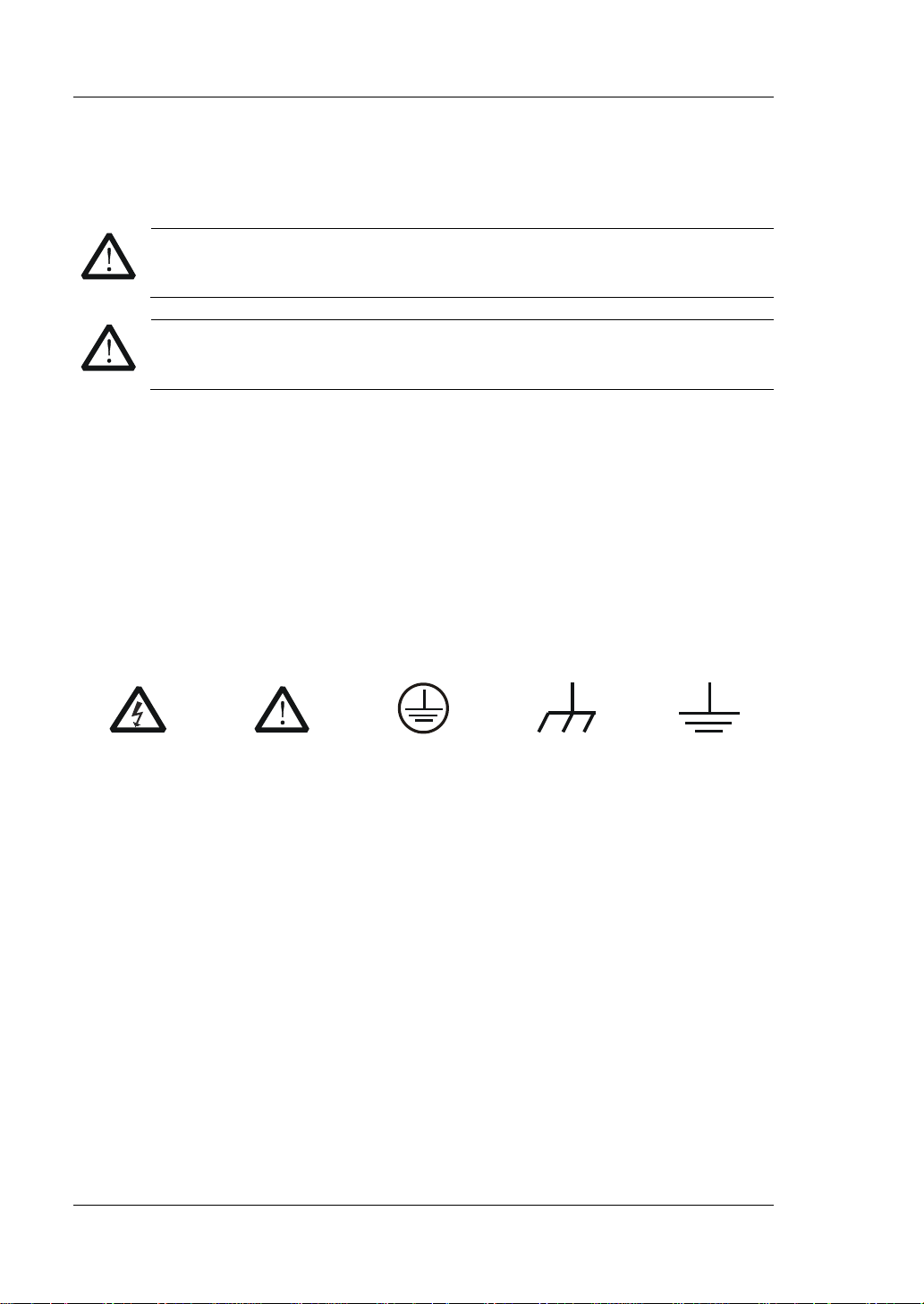
Hazardous
Voltage
Safety Warning
Protective Earth
Terminal
Chassis Ground
Test Ground
Safety Notices and Symbols
Safety Notic e s in this Manua l:
Indicates a potentially hazardous situation or practice which, if not
Indicates a potentially hazardous situation or practice which, if not
Safety Terms on the Product:
result in damage to the product or other devices connected to the
Safety Symbols on the Product:
IV DL3000 User’s Guide

RIGOL
CAUTION
WARNING
supply.
Care and Cleaning
Care
Do not store or leave the instrument where it may be exposed to direct sunlight for
long periods of time.
Cleaning
Clean the instrument regularly according to its operating conditions.
1. Disconnect the instrument from all power sources.
2. Clean the external surfaces of the instrument with a soft cloth dampened with
mild detergent or water. When cleaning the LCD , take care to av oid sca rifying it .
To avoid damage to the instr ument, do n ot expose it to caustic liquids.
To avoid short-circuit resulting from moist ure or personal injuries, ensure
that the instrument is completely dry before connecting it to the power
Environmental Consideratio ns
The following symbol indicates that this product complies with the WEEE Directive
2002/96/EC.
Product End-of-Life Handling
The equipment may contain substances that could be har mful to the en vironm ent o r
human health. To avoid the release of such substances into the environment and
avoid harm to human health, we recommend you to recycle this product
appropriately to ensure that most materials are reused or recycled properly. Please
contact your local authorities for disposal or recycling information.
You can click on the following link
http://www.rigol.com/Files/RIGOL_RoHS2.0&WEEE.pdf to download the latest
version of the RoHS&WEEE certification file.
DL3000 User’s Guide V

RIGOL
DL3000 Series Overview
DL3000 is a cost-effective programmable DC electronic load with high performance.
With a user-friendly interface and superb performance specifications, DL3000 series
provides variou s i nt e rf aces for remote communication to meet your divers i fi ed test
requirements. It can be widely used in various industries, such as automotive
electronics, aerospace, and fuel cells.
Main Features:
DL3021/DL3021A: single channel, DC 150 V/40 A, total power up to 200 W
DL3031/DL3031A: sin gle c hannel, DC 150 V/60 A, total power up to 350 W
Dynamic mode: up to 30 kHz
Adjustable current rising speed: 0.001 A/μs to 5 A/μs
Min. readback resolution: 0.1 mV, 0.1 mA
4.3-inch TFT LCD, capable of displaying multiple parameters and states
simultaneously
Overvoltage/overcurrent/overpower/overtemperature/reverse voltage
protection
4 static mod e s: CC, CV, CR, CP
3 dynamic modes: continuous, pulsed, toggled
List func t ion suppor t s e diting as many a s 512 steps
Battery test function, OCP test, OPP test, factory test function, etc.
Short-circuit test function
Power-off memory function
Built-in RS232/USB/LAN communication interface
USB-GPIB interface converter (optional)
VI DL3000 User’s Guide

RIGOL
Tip
RIGOL (www.rigol.com).
Document Overview
Chapter 1 Quick Start
This chapter introduces some basic information that you s houl d know when you use
the DL3000 series electronic load for the first time. This section contains the
following contents: out -of-box inspection method, t he appeara nce and dimensions of
the instrument, descriptions of the fr ont/rear panel, how to connect the power supply,
how to carry out the turn-on checkout, how to replace the fuse, a brief introduction
about the user interface, how to use the built-in help system, and how to set the
parameters.
Chapter 2 Front Panel Ope r a tio n s
This chapter gives a detailed description about the functions of all the keys on the
front panel of DL3000 series and detailed operation met ho ds.
Chapter 3 Remote Control
This chapter introduces how to remotely control the instrument.
Chapter 4 Troubleshooting
This chapter introduces the p ossible failu res and solutions in using the DL3000 series
electronic load.
Chapter 5 Appendix
This chapter provides the order information and warranty information about the
DL3000 series electronic load.
Index
This chapter provides keyword sea rch informat ion, enabling yo u to quickly locat e the
desired information.
For the latest version of this manual, download it from the official website of
Format Conventions in this Manual
1. Key
(1) The key on the front panel is denoted by the format of "Key Name (Bold) +
T e xt Box" in the manual. F or example, ON/OFF denotes the "ON/OFF" key .
(2) Use the screen shot to indicate the key. For example, denotes the
Power key.
2. Menu Softkey
The menu softkey is denoted by the format of “Menu Word (Bold) + Character
DL3000 User’s Guide VII
RIGOL
Model
No. of Channels
Voltage
Current
Power
DL3021/DL3021A
1
DC 150 V
40 A
200 W
DL3031/DL3031A
1
DC 150 V
60 A
350 W
Shading”. For example, Interface denotes the “Interface” menu softkey under
Utility.
Content Con v entions in th is Ma n ual
The number of channels and the rated values of input parameters for the DL3000
series are listed in the following t able. Unless otherwise specified, this manual takes
DL3031A as an example to illustrate the functions and operation methods of the
DL3000 se ries.
VIII DL3000 User’s Guide

Contents RIGOL
Contents
Guaranty and Declaration ......................................................................... I
Safety Requirement ................................................................................ II
General Safety Summary ........................................................................... II
Safety Not ices and Symbol s ...................................................................... IV
Care and Cleaning .................................................................................... V
Environmental Considerations .................................................................... V
DL3000 Series Overview .......................................................................... VI
Document Overview ............................................................................... VII
Chapter 1 Quic k S tart ......................................................................... 1-1
General Inspection ................................................................................ 1-2
Appearance and Dime nsions ................................................................... 1-3
Front Panel ........................................................................................... 1-4
Rear Panel ........................................................................................... 1-10
Turn-on Checkout ................................................................................. 1-13
To Connect to Power Supply............................................................ 1-13
To Power On the Inst ru ment ........................................................... 1-14
Fuse Replacement ................................................................................ 1-15
User Interface ...................................................................................... 1-16
To Use the Built-in Help System ............................................................. 1-17
Parameter Setting Method ..................................................................... 1-18
Chapter 2 Front Panel Operations ...................................................... 2-1
Local/Remote Operation Mode ................................................................ 2-2
Local Operation Mode ...................................................................... 2-2
Remote Operation Mode .................................................................. 2-2
Static Operation Mode ........................................................................... 2-3
Constant Current (CC) Mode ............................................................ 2-3
Constant Voltage (CV) Mode ............................................................ 2-7
Constant Resistance (CR) Mode ....................................................... 2-11
Constant Power (CP) Mode ............................................................. 2-15
Transient Test Function ......................................................................... 2-18
CC Continuous Mode (Con) ............................................................. 2-18
CC Pulsed Mode (Pul) ..................................................................... 2-25
CC Toggled Mode (Tog) .................................................................. 2-32
List Operation Function (List) ................................................................. 2-38
Application Function ............................................................................. 2-45
OCP Test Function .......................................................................... 2-45
OPP Test Function .......................................................................... 2-53
Battery Test Function ..................................................................... 2-60
Advanced Function ............................................................................... 2-65
Factory Te st F unc tion ..................................................................... 2-65
CC+CV Function ............................................................................ 2-69
DL3000 User’s Guide IX

RIGOL Contents
Waveform Display Function ................................................................... 2-73
Input Control ....................................................................................... 2-78
Turn On/Off the Input .................................................................... 2-78
Von Latch Function ........................................................................ 2-78
Short-circuit Operation ................................................................... 2-79
Trigger Operation .......................................................................... 2-80
Protection Function .............................................................................. 2-82
Sense Working Mode ............................................................................ 2-84
Function of Terminals on the Rear Panel ................................................. 2-86
Store and Recall ................................................................................... 2-87
Cursor .......................................................................................... 2-88
Save ............................................................................................. 2-88
Read ............................................................................................ 2-90
Delete .......................................................................................... 2-91
Copy and Paste ............................................................................. 2-91
System Utility Function ......................................................................... 2-92
System ......................................................................................... 2-93
Communication Interface Set ti ng .................................................... 2-97
System Info ................................................................................ 2-105
Reset.......................................................................................... 2-105
Option Configuration .................................................................... 2-110
Chapter 3 Remote Control ................................................................. 3-1
Remote Control via USB .......................................................................... 3-2
Remote Control via LAN .......................................................................... 3-5
Remote Control via GPIB ......................................................................... 3-8
Remote Control via RS232 .................................................................... 3-11
Chapter 4 Troubleshooting ................................................................ 4-1
Chapter 5 Appendix ........................................................................... 5-1
Appendix A: Order Information ................................................................ 5-1
Append i x B: Warranty ............................................................................. 5-4
Index ........................................................................................................ 1
X DL3000 User’s Guide

Chapter 1 Quick Start RIGOL
Chapter 1 Quick Start
Contents in this chapter:
General Inspection
Appearance and Dime nsions
Front Panel
Rear Panel
Turn-on Checkout
Fuse Replacement
User Interface
To Use the Built-in Help System
Parameter Setting Method
DL3000 User’s Guide 1-1

RIGOL Chapter 1 Quick Start
General Inspection
1. Inspect the packaging
If the packa gi ng has be en da m age d, do n ot dis po se t he da m age d pac ka gin g o r
cushioning materials until the shipment has been check ed for completeness an d
has passed both electrical and mechanical tests.
The consigner or carrier shall be liable for the damage to the instrument
resulting from shipment. RIGOL would not be responsible for free
maintenance/rework or replacement of the instrument.
2. Inspect the instrument
In case of any mechanical damage, missing parts, or failure in passing the
electrical and mechanical tests, contact your RIGOL sales representative.
3. Check the accessories
Please check the accessories according to the packing lists. If the accessories
are damaged or incomplet e , pl e a s e contact your RIGOL sales representative.
1-2 DL3000 User’s Guide

Chapter 1 Quick Start RIGOL
Appearance and Dimensions
Figure 1-1 Front View Unit: mm
Figure 1-2 Side View Unit: mm
DL3000 User’s Guide 1-3
RIGOL Chapter 1 Quick Start
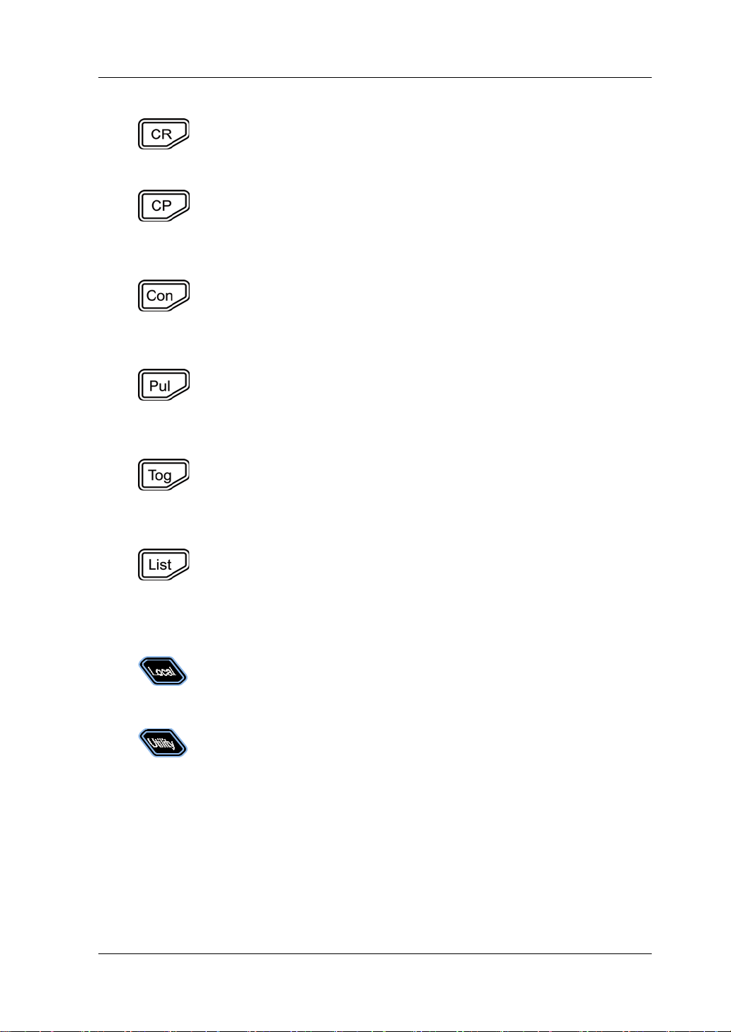
Pressing this key can enter the constant current (CC) mode. You
rate, and starting voltage.
Pressing this key can enter the constant voltage (CV) mode. You
can set parameters for the mode, such as voltage and range.
7
12 11 10 9 8
1 2 3 4 5 6
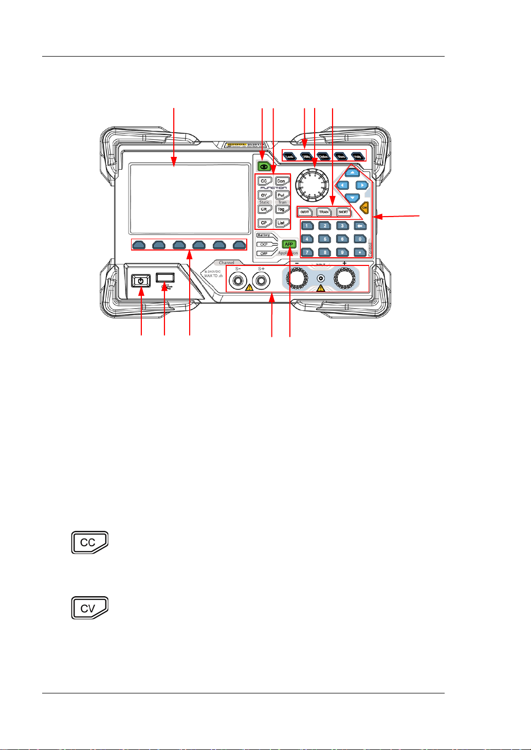
Front Panel
Figure 1-3 Front Panel
1. LCD
4.3-inch TFT LCD, used to display the system status, input parameters, menu
setting, prompt message, etc.
2. Waveform Display Key
Pressing this key can ent er the w a vef orm displa y int erface . You can observe the
change s of parameters from the dynamic wavefo r m.
3. Function Keys
Provide four static operating modes and three dynamic test functions. In
addition, there is also a key used for list operation.
(1) CC key
can set parameters for the mode, such as current, range, slew
(2) CV key
1-4 DL3000 User’s Guide
Chapter 1 Quick Start RIGOL
Pressing this key can enter the constant resistance (CR) mode.
range.
Pressing this key can enter the constant power (CP) mode. You
of the voltage.
Pressing this key can enter the continuous (Con) mode. You can
rising slew rate, and falling slew rate.
Pressing this key can enter the pulsed (Pul) mode. You can set
slew rate, and falling slew rate.
Pressing this key can enter the toggled (Tog) mode. You can set
slew rate, and falling slew rate.
Pressing this key can enter the list operation interface. You can
is cycled, a nd the number of steps.
In remote operation mode, when you press this key, you can
switch to the local mode.
System
Configures para met ers f or rem ot e commu n icat io n in te rface s
(3) CR key
You can set parameters for the mode, such as resistance and
(4) CP key
can set parameters for the mode, such as power and upper limit
(5) Co n key
set parameters for the mode, such as range, Level A, Level B,
(6) Pul key
parameters for the mode, such as range, Level A, Level B, rising
(7) Tog key
parameters for the mode, such as range, Level A, Level B, rising
(8) List ke y
set parameters such as mode, range, the number of times the list
4. System Function Keys
(1) Local/remote switch key
(2) System utility function key
Sets the system language, power-on value, brightness,
short-circuit function, digital input/output, beeper (on/off),
Sense function, log, Von Latch function, voltage monitoring
output terminal, and current monitoring output terminal.
Interface
(GPIB/USB/RS232/LAN).
DL3000 User’s Guide 1-5
RIGOL Chapter 1 Quick Start
System Info
hardware versions, FPGA version, boo t version, sys t e m boot
settings, For default settings, refer to Table 2-3.
Provides advanced fun ctions. Currently, the factory test function
Saves, reads, deletes, copies, and pastes the files. The
files can be stored in the instrument.
Enters the built-in help system. You can view releva nt help
Enables or disables the sink function of the load.
Turns on or off the transient trigger function.
Enables or disables the short circuit function of the load.
Displays the manufacturer, device model, software and
times, calibration date, and product serial number.
Reset
Restores the instrument settings to its factory default
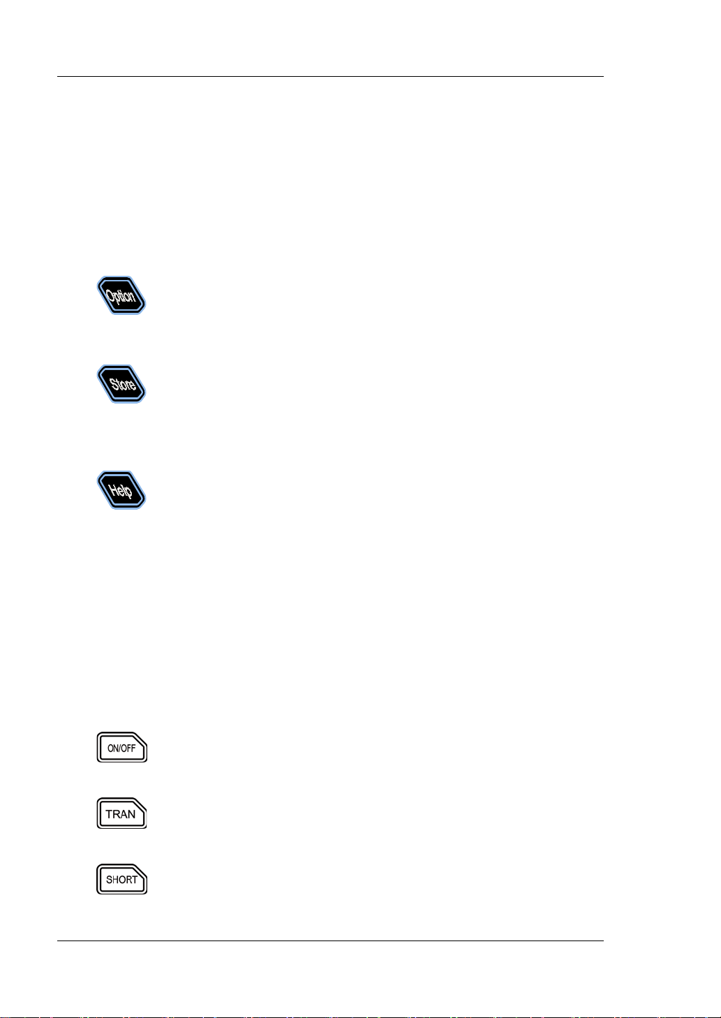
(3) Advanced function key
and CC+CV function are supported.
(4) Storing and recalling operation key
instrument provides an internal non-volatil e memo ry ("Disk C")
and supports an external memory ("Disk D"). A maximum of 100
(5) Help key
information for any key or menu key on the front p an e l .
5. Knob
(1) Switch the parameters or parameter values.
(2) Increases (rotate clockwise) or decreases (rotate counterclockwise) the
value at the cursor.
Note: Rotating the knob in different i nte rfaces can produce different operation
results. Here introduces its common usage. For other specific usages and
operation methods, refer to details in relevant chapters.
6. Input Control Keys
(1) Input on/off key
(2) Transient trigger key
(3) Short-circuit key
1-6 DL3000 User’s Guide

Chapter 1 Quick Start RIGOL
Switch the parameter focus.
arrow key to decre ase the val ue at the cu rsor.
Numer ic keys
Backspace key
7. Control Keys
Control keys include the arrow keys, numeric keys, and confirmation key.
Pressing the control keys in different interfaces can produce different oper ati o n
results.
Note: Here introdu ces t heir com mon usa ge. F o r the ir other specific usages an d
operation methods, refer to details in relevant chapters.
(1) Arrow keys (Up/Down/Left/Right arrow key)
M ove t h e cu rsor.
Switch th e parameters or parameter values.
When setting parameters, use the Up arrow key to
increase the value at the cursor or use the Down
(2) Confirmation key
Confirms the parameter setting.
(3) Numeric k eys and backspace k ey
8. Application Key
Enables one of the following three application functions: OCP test, OPP test, or
Battery test. You can press this key to switch among the three functions.
9. Channel Terminals
Channel terminals include the channel input terminals and Sense terminals, as
shown in Figure 1-4.
The numeric keys contain numbers (0-9)
and a decimal point. You can use the
numeric keys to enter a value for the
parameter.
Backsp ace key
Deletes the unwanted characters or
numerical values that have been entered.
DL3000 User’s Guide 1-7

RIGOL Chapter 1 Quick Start
CAUTION
than 70 V.
Channel Input Terminals
Sense Terminals
A
Outer Nut
Shield
Figure 1-4 Channel Terminals
(1) Channel input terminal: Connects with the device under test (DUT, such as
battery and power supply), which is used for inputting voltage and current.
Note: Connect the positive polarity of the load to the (+) terminal of the
channel output, and the negative polarity of the load to the (-) terminal of
the channel output.
(2) Sense terminal: When the DUT outputs large current, the sense terminal
can be used to accurately measure the voltage across the output terminals
of the DUT to compensate for the voltage drop on the load.
Connection methods for the input terminals (see Figure 1-5):
a) Rotate the oute r nut of the in put t erminal counte r clockwise t o remo ve it.
b) Connect the test lead to Position A of the input terminal.
c) Fasten the outer nut of the input terminal clockwise.
d) Secure the shield to the terminal and then tighten the screw.
1-8 DL3000 User’s Guide
Figure 1-5 Connect Input Terminals
To avoid electric shock, ensure that you have installed the shield
when the DC voltage output from the DUT is equal to or greater

Chapter 1 Quick Start RIGOL
10. Menu Keys
You can press the specified menu key to execute the corresponding operation
displayed at the bottom of the interface on the screen.
11. USB Host
(1) The instrument is regarded as the " master device". Y ou can use the data line
to con nect it to t he USB storage device (e.g. U-d isk) to realize external
storage or recalling.
(2) Us e the USB-GPIB interface converter to extend the GPIB interface for the
load, and then use the GPIB cable to connect the load to the PC to realize
remote contr ol .
12. Power Key
Turn on or off the instrument.
DL3000 User’s Guide 1-9

RIGOL Chapter 1 Quick Start
9
11
1 2 3
4
Rear Panel
10
Figure 1-6 Rear Panel
1. Air Outlet
Decrease the temperature inside the instrument to ensure its performance.
When you place the instru ment on the wo rkbench or install it i nto the ra ck, kee p
the air outlet from a distance of 10 cm to ensure adequate ventilation.
2. Digital I/O
The digital I/O interface supp orts the di gital input (Terminal 1, input voltage 3.3
V or 5 V) and output (Terminal 2, output voltage 3. 3 V) .
Note: This function is a s tandard configuration for DL3031A/DL3021A, and it is
an option for DL3031/DL3021. Therefore, for the DL3031/DL3021 model, you
need to purchase the digital I/O opti on (with the orde r No. DIGITALIO-DL3).
3. LAN Interface
LAN interface is of the Non-Auto-MDIX type. The instrument can be connecte d
to the Local A rea Netw ork (L AN) via the interf ace, so that y ou can realize re mote
control for the instrument. The instrument is in compliance with the standards
specified in LXI Device Sp ecification 2011. It can be used to set up a test syste m
with other standard devices to easily realize the system integration.
4. AC Selector
Selects the voltage that matches with the actual AC input power. For details,
5
6
7
8
1-10 DL3000 User’s Guide

Chapter 1 Quick Start RIGOL
CAUTION
scale by using the AC selector.
CAUTION
To avoid electric sho ck or fire disaster , please use th e s pecified fuse
and ensure that no short circuit occurs to the fuse holder.
refer to "Fuse Rating" on the rear panel or Table 1-2.
The electronic load supports two AC voltage ratings: 115 V and 230 V.
Please
select the proper voltage scale based on the AC rating in your country.
When the switch lever is located at a different position, it indicates that a
different voltage rating is selected. When the switch lever is at the left, it
indicates that 230 V is se lected. When the switch lev er is at t he right, it in dicates
that 115 V is selected.
5. AC Power Cord Connector
AC power input interface. Plug the specified power cord available in the
accessories into the AC power cord connector of the instrument, and then
connect the instrument to the AC power.
Before connecting the AC power, please select the proper voltage
6. Fuse
When leaving the factory, the instrument has installed a fuse that conforms to
the local standard. For fuse replacement, refer to "Fuse Replacement".
7. Fuse Rating
The required fuse rating is related to the actual input voltage, please refer to th e
"fuse rating" on the rear panel of the load or refer to Table 1-2.
8. RS232 Interface
Serial communication interface. Use the 9-pin RS232 cable to build
communication with the PC to realize remote control.
9. USB Device
The instrument can be regarded as the "standby device" to connect to the
external USB dev ice (e.g. PC) to rea l ize remote cont rol.
10. Voltage Monitorin g Output Terminal
The voltage monitoring output terminal outputs the signal in analog quantity.
You can connect a device such as a digital oscilloscope through the terminal to
display the voltage output from the output terminal, so as to monitor the
changes of input voltage of the load.
DL3000 User’s Guide 1-11

RIGOL Chapter 1 Quick Start
11. Current Monitoring Output Terminal
The current monitoring output terminal outputs the signal in analog quantity.
You can connect a device such as a digital oscilloscope through the terminal to
display the current output from the output terminal, so as to monitor the
changes of input current of the load.
1-12 DL3000 User’s Guide

Chapter 1 Quick Start RIGOL
AC Input Power
AC Selector
±(10% of AC input + 115 Vac), 50 Hz to 60 Hz
115
±(10% of AC input + 230 V ac) (max: 250 V ac), 50 Hz to 60 Hz
230
WARNING
grounded.
Turn-on Checkout
To Connect to Power Supply
Two kinds of AC power inputs are supported by the DL3000 series. When it is
connected to different power sources, the AC selector setting on its rear panel is
different, as shown in Table 1-1.
Table 1-1 AC Input Power Specification and AC Selector Setting
Please strictly follow the steps below to connect the DL3000 electronic load to the
power supply.
1. Check the input power
Ensure that the AC power to be connected t o t he load conforms to the AC input
power requirement specified in Table 1-1.
2. Check the AC selector
Ensure that the AC selector setting (115 V or 230 V) on the rear panel of the load
matches the actual AC input power (For the match relationship, refer to Table
1-1).
3. Check the fuse
When leaving the factory, the load has installed a fuse that conforms to the
destination country standard. Please ref er to the "fuse rating" on the rear panel
of the load or refer to Table 1-2 to ensure that the fuse matches the actual AC
input power.
4. Connect the AC power
Plug the specified power cord available in the accessories into the AC power
supply connector of the instrument, and then connect the instrument to the
properly grounded AC power.
To avoid electric shock, ensure that the instrument is correctly
DL3000 User’s Guide 1-13
RIGOL Chapter 1 Quick Start
CAUTION
Ensure that the AC selecto r setting on the rear panel of the instrument
be burned out.
CAUTION
then enable the input of the electronic load. Otherw is e, the instrument
or the device un der test (DUT) wi l l be da maged.
CAUTION
burned out.
Tip
After powerin g off t he elect ronic l oad, plea se wai t for at leas t 1 s bef ore you power
it on again.
To Power On the Instrument
After the instrument is con nected t o the power sour ce, press the Power key
the left bottom of the front panel to power on the instrument. When the instrument
is turned on, it will undergo a self-test. If the instrument passes the self-test, the
welcome interface is displayed; otherwise, self-test failure informat ion will be
displayed. At this time, please conta ct RIGOL distributors.
matches the actual AC input voltage , otherwise, the electronic load will
After starting the instrument, please connect the cable properly, and
Please pay attention to the positive and negative polarities of the
electronic load to avoid wrong connection. Otherwise, the load will be
at
1-14 DL3000 User’s Guide

Chapter 1 Quick Start RIGOL
Input Voltage
Fuse Rating
115 Vac
T0.315 A/250 V
230 Vac
T0.20 A/250 V
WARNING
supply before replacing the fuse; to avoid electric shock or fire disaster,
conforms to the voltage specification.
Fuse Holder
Fuse
Fuse Replacement
The fuse specification is related to the actual input voltage, as shown in Table 1-2.
Table 1-2 Fuse Rating
When leaving the factory, the instrument has installed a fuse that conforms to the
local standard. If the fuse is required to be replaced, select a fuse that matches the
actual input voltage and perform the following steps.
1. Turn off the instrument, and then disconnect the instrument from the power
source. Remove the power cord.
2. Insert a slotted screwdriver into the slot of the fuse holder to pry it out, as
shown in Figure 1-7.
Figure 1-7 Fuse Replacement
3. Take out the fuse and replace it according to the fuse rating (refer to the "Fuse
Rating" on the rear panel of the instrument or Table 1-2).
4. Mount the fuse holder (pay attention to its direction when mounting it).
To avoid personal injuries, t urn off the instrume nt and cut off the power
before connecting to the AC power, select the voltage specification that
matches the actual input voltage and replace a proper fuse that
DL3000 User’s Guide 1-15
RIGOL Chapter 1 Quick Start
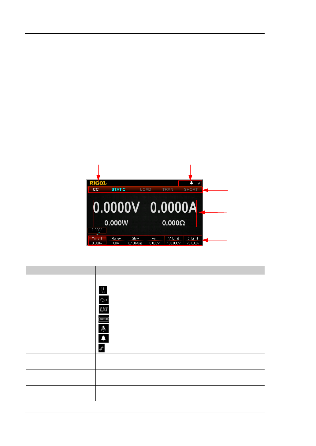
No.
Name
Description
1
RIGOL
Company Logo
: indicates that the instrument is remotely controlled.
Displays the function state of the load in a real -time
manner.
Actual Input
Value
Displays the function menu. Press the specified key below
to select the specified menu item.
1
2 3 4
5
User Interface
The user interface of the DL3000 series consists of main interface, guide interface,
and function interface. In the main interface, you can set and view the information
about the channel input; in the guide interface, you can directly set the parameters
according to the guide diagram and view the parameter information; in the function
interface (including the waveform interface), you can set and view the information
about the functions. When the instru ment powers on , it e nters t he main interf ace by
default. This section mainly introduces the main interface of the electronic load. The
guide interface and function interface will be introduced in "Front Panel
Operations".
The main interface is sh own in Figure 1-8. For the des criptions of the main inte rface,
refer to Table 1-3.
Figure 1-8 Main Interface
Table 1-3 Main Interface Description
: indicates that the overtemperature protection occurs.
: indicates that the USB device is recognized.
: indicates that the network is connected.
: indicates that GPIB is connected.
2
System Status
Icon
: indicates that the beeper is off.
: indicates that the beeper is on.
3 Function State
4
Displays the actual input voltage, sink current, etc.
5 Menu Item
1-16 DL3000 User’s Guide
Chapter 1 Quick Start RIGOL
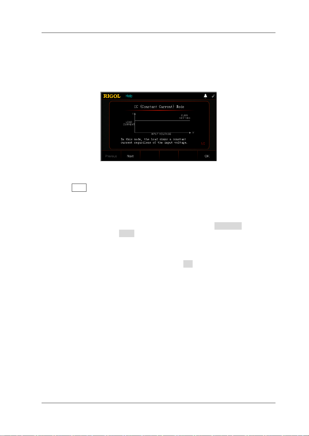
To Use the Built-in Help System
The built-in help system provides help information for any key on the front panel
(except parameter input area) and menu keys, which are convenient for you to get
the descriptions of the function keys or menus, as shown in Figure 1-9.
Figure 1-9 Help Information Interf ace
1. Get the built-in help information
Press Help, and then "Help" will be displayed at the top of the interface, being
highlighted. At this time, press the corresponding function key or menu key to
enter the corresponding help information interface.
2. Page up/down opera tion
If the help info rmation is displa yed in seve ral pa ges, press Previous to go to the
previous page or press Next to go to the next page. Y ou can also use the arrow
keys or the knob to page up/down the help information.
3. Exit the current help information interface
When the help information is displayed, press OK to exit the current help
information interface and return to the previous interface.
DL3000 User’s Guide 1-17

RIGOL Chapter 1 Quick Start
Parameter Setting Method
Most parameters can be set by operating the keys on the front panel. The common
setting methods are listed below. The setting method for certain parameters is
different from the methods below, refer to the relevant chapters of this manual for
the further explanation.
Method 1: Use the numeric keys
1. In the main interface, press the specified menu key to switch the parameter
focus; in the guide int erf ace, use the arrow keys to switch the parameter focus.
2. Enter a value by using the numeric key. While entering a name, press
delete the unwanted character if necessary.
3. When setting resistance, press the specified menu key and select "Ω" or "kΩ" to
be the unit.
When setting period/width, press the specified menu key and select "ms" or "s"
to be the unit.
When setting frequency, press the specified menu key and select "Hz" or "kHz"
to be the unit.
When setting other parameters, press OK to confirm the input.
Method 2: Use the knob or the arrow keys
1. In the main interface, press the specified menu key to switch the parameter
focus.
2. Press the Left/Right arrow key to move the cursor to a desired position.
3. Press the Up/Down arrow key or rotate the knob to modify the value.
to
1-18 DL3000 User’s Guide
 Loading...