

Page 1

RIGOL
User’s Guide
DL3000 Series Programmable DC
Electronic Load
Aug. 2017
RIGOL TECHNOLOGIES, INC.
Page 2

Page 3

RIGOL
Guaranty and Declaration
Copyright
© 2017 RIGOL TECHNOLOGIES, INC. All Rights Reserved.
Trademark Information
RIGOL is a registered trademark of RIGOL TECHNOLOGIES, INC.
Publication Number
UGJ01104-1110
Software Version
00.01.01
Software upgrade might change or add product features. Please acquire the latest
version of the manual from RIGOL website or contact RIGOL to upgrade the
software.
Notices
RIGOL produ cts are cove red by P.R.C. and f oreign pa tents, issue d and pendin g.
RIGOL reserves the right to modify or change parts of or all the specifications
Information in this publica tion re places all previ ously released materials.
Information in this publication is subject to change without notice.
RIGOL shall not be liable for either incidental or consequential losses in
Any part of th is d ocu ment is f orbi dden to be c opie d, ph oto copie d, o r rea r ran ged
and pricing policies at the company’s sole decision.
connection with the furnishing, use, or performance of this manual, as well as
any information contained.
without prior written approval of RIGOL.
Product Certification
RIGOL guarantees that this product conforms to the national and industrial
standards in China as well as the ISO9001:2008 standard and the ISO14001:2004
standard. Other international standard conformance certifications are in progress.
Contact Us
If you have any problem or requirement when using our products or this manual,
please contact RIGOL.
E-mail: service@rigol.com
Website: www.rigol.com
DL3000 User’s Guide I
Page 4

RIGOL
Safety Requirement
General Safety Summary
Please review the following safety precautions carefully before putting the
instrument into operation so as to avoid any personal injury or damage to the
instrument and any product connected to it. To prevent potential hazards, please
follow the instructions specified in this manual to use the instrument properly.
Use Proper Power Cord.
Only the exclusive power cord designed for the instrument and authorized for use
within the local country could be used.
Ground the Instrument.
The instrument is grounded th rou gh t he Protective Earth lead of the p ower cord. To
avoid electric shock, con nect the earth terminal of the power cord to the Protective
Earth terminal before connecting any input or output terminals.
Connect the Probe Correctly.
If a probe is used, the probe ground lead must be connected to earth ground. Do not
connect the ground lead to high v olta ge. Imp roper w ay of connection c ould result in
dangerous voltages being present on the connectors, controls or other surfaces of
the oscilloscope and probes, which will cause potential hazards for operators.
Observe All Terminal Ratings.
To avoid fire or shock hazard, observ e all rat ings and ma rkers on the instrume nt and
check your manual for more information about ratings before connecting the
instrument.
Use Proper Overvoltage Protection.
Ensure that no over voltage (su ch as that cause d by a bolt of lightning ) can reach the
product. Otherwise, the operator might be exposed to the danger of an electric
shock.
Do Not Operate Without Covers.
Do not operate the instrument with covers or panels removed.
Do Not Insert Objects Into the Air Outlet.
Do not insert objects into the air outlet, as doing so may cause damage to the
instrument.
Use Proper Fuse.
Please use the specified fuses.
II DL3000 User’s Guide
Page 5

RIGOL
Avoid Circuit or Wire Exposure.
Do not touch exposed junctions and components when the unit is powered on.
Do Not Operate With Suspected Failures.
If you suspect that any damage may occur to the instrument, have it inspected by
RIGOL authorized personnel before further operations. Any maintenance,
adjustment or replacement especially to circuits or accessories must be p erformed
by RIGOL authorized personnel.
Provide Adequate Ventilation.
Inadequate ventilation may cause an increase of temperature in the instrument,
which would cause damage to the instrument. So please keep the instrument well
ventilated and inspect the air outlet and the fan regularly.
Do Not Operate in Wet Conditions.
To avoid short circuit inside the instrument or electric shock, never operate the
instrument in a humid environment.
Do Not Operate in an Explosive Atmosphere.
To avoid personal injuries or damage to the instrument, never operate the
instrument in an explosive atmosphere.
Keep Product Surfaces Clean and Dry.
T o a void dust or moisture from af fecting the pe rformance of the inst rument, keep th e
surfaces of the instrument clean and dry.
Prevent Ele c tr o static Imp act.
Operate the instrume nt i n an el ectr ostatic dischar ge protectiv e envi ron ment to a void
damage induced by static discharges. Always ground both the internal and external
conductors of cables to releas e sta t i c be fore making connections.
Use the Battery Properly.
Do not expose the battery (if available) to high temperature or fire. Keep it out of the
reach of children. Improper change of a battery (lithium battery) may cause an
explosion. Use the RIGOL specified battery only .
Handle with Caution.
Please handle with care during transportation to avoid damage to keys, knobs,
interfaces, and other parts on the panels.
DL3000 User’s Guide III
Page 6
RIGOL
WARNING
CAUTION
DANGER
It calls attention to an operation, if not correctly performed, could
CAUTION
It calls attention to an operation, if not correctly performed, could
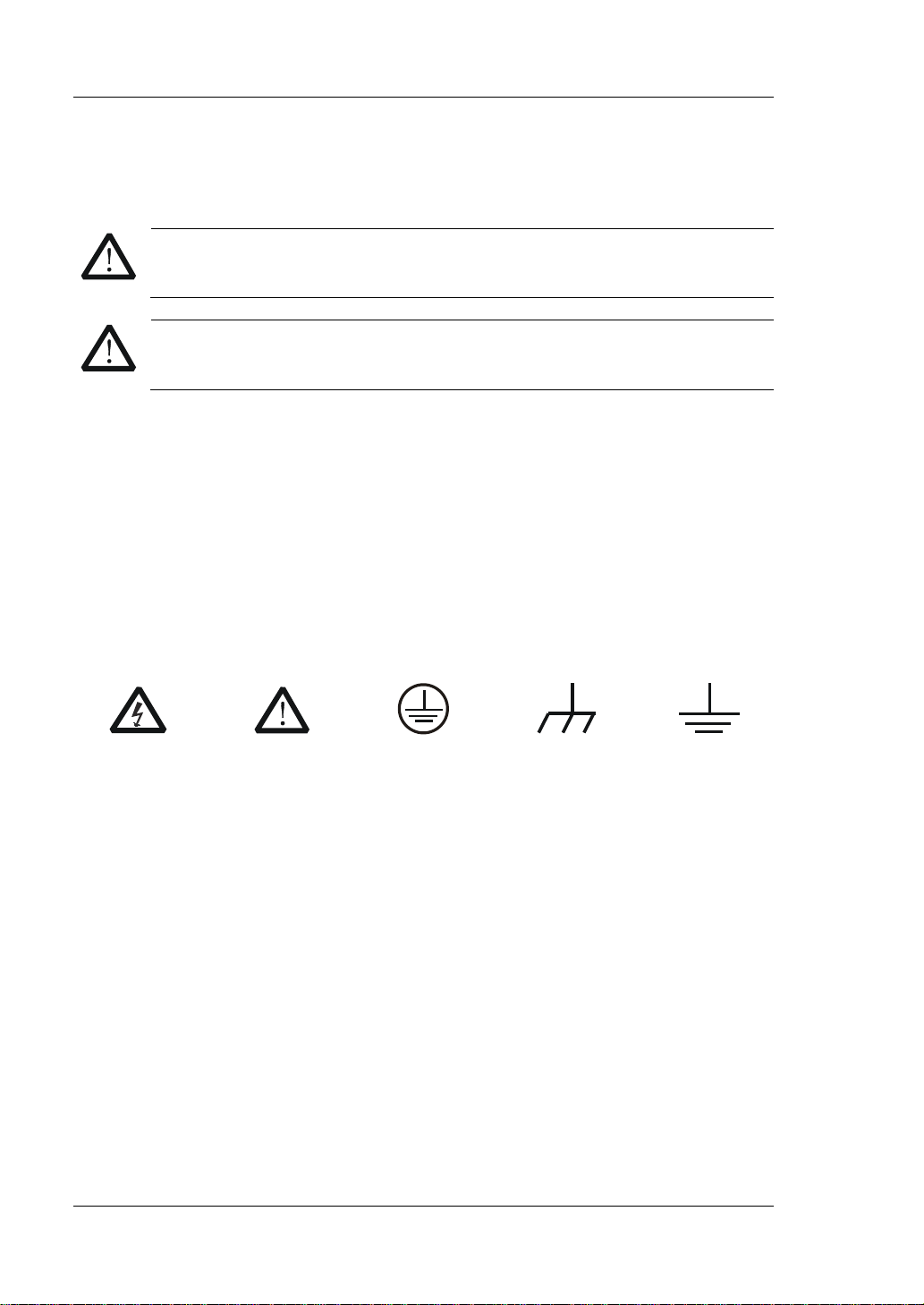
Hazardous
Voltage
Safety Warning
Protective Earth
Terminal
Chassis Ground
Test Ground
Safety Notices and Symbols
Safety Notic e s in this Manua l:
Indicates a potentially hazardous situation or practice which, if not
avoided, will result in serious injury or death.
Indicates a potentially hazardous situation or practice which, if not
avoided, could result in damage to the product or loss of important data.
Safety Terms on the Product:
result in injury or hazard immediately.
WARNING It calls attention to an operation, if not correctly performed, could
result in potential injury or hazard.
result in damage to the product or other devices connected to the
product.
Safety Symbols on the Product:
IV DL3000 User’s Guide
Page 7
RIGOL
Care and Cleaning
Care
Do not store or leave the instrument where it may be exposed to direct sunlight for
long periods of time.
Cleaning
Clean the instrument regularly according to its operating conditions.
1. Disconnect the instrument from all power sources.
2. Clean the external surfaces of the instrument with a soft cloth dampened with
mild detergent or water. When cleaning the LCD , take care to av oid sca rifying it .
CAUTION
To avoid damage to the instrument, do not expose it to caustic liquids.
WARNING
To avoid short-circuit resulting from moist ure or personal injuries, ensure
that the instrument is completely dry before connecting it to the power
supply.
Environmental Consideratio ns
The following symbol indicates that this product complies with the WEEE Directive
2002/96/EC.
Product End-of-Life Handling
The equipment may contain substances that could be har mful to the en vironm ent o r
human health. To avoid the release of such substances into the environment and
avoid harm to human health, we recommend you to recycle this product
appropriately to ensure that most materials are reused or recycled properly. Please
contact your local authorities for disposal or recycling information.
DL3000 User’s Guide V
Page 8

RIGOL
DL3000 Series Overview
DL3000 is a cost-effective programmable DC electronic load with high performance.
With a user-friendly interface and superb performance specifications, DL3000 series
provides variou s i nt e rf aces for remote communication to meet your divers i fi ed test
requirements. It can be widely used in various industries, such as automotive
electronics, aerospace, and fuel cells.
Main Features:
DL3021/DL3021A: single channel, DC 150 V/40 A, total power up to 200 W
DL3031/DL3031A: sin gle c hannel, DC 150 V/60 A, total power up to 350 W
Dynamic mode: up to 30 kHz
Adjustable current rising speed: 0.001 A/μs to 5 A/μs
Min. readback resolution: 0.1 mV, 0.1 mA
4.3-inch TFT LCD, capable of displaying multiple parameters and states
simultaneously
Overvoltage/overcurrent/overpower/overtemperature/reverse voltage
protection
4 static mod e s: CC, CV, CR, CP
3 dynamic modes: continuous, pulsed, toggled
List func tion supports editing as many as 512 ste ps
Battery test function, OCP test, OPP test, factory test function, etc.
Short-circuit test function
Power-off memory function
Built-in RS232/USB/LAN communication interface
USB-GPIB interface converter (optional)
VI DL3000 User’s Guide
Page 9
RIGOL
Tip
RIGOL
Document Overview
Chapter 1 Quick Start
This chapter introduces so me basic information that y ou should know when yo u use
the DL3000 series electronic load for the first time. This section contains the
following contents: out -of-box inspection method, th e appeara nce and dimensions of
the instrument, descriptions of the front /rear panel, how to connect the power supply,
how to carry out the turn-on checkout, how to replace the fuse, a brief introduction
about the user interface, how to use the built-in help system, and how to set the
parameters.
Chapter 2 Front Panel Ope r a tio n s
This chapter gives a detailed description about the functions of all the keys on the
front panel of DL3000 series and detailed operation met ho ds.
Chapter 3 Remote Control
This chapter introduces how to remotely control the instrument.
Chapter 4 Troubleshooting
This chapter introduces the p ossible failu res and solutions in using the DL3000 series
electronic load.
Chapter 5 Specifications
This chapter lists all the performance specifications of the DL3000 series electronic
load.
Chapter 6 Appendix
This chapter provides the order information and warranty information about the
DL3000 series electronic load.
Index
This chapter provides keyword sea rch informat ion, enabling yo u to quickly locat e the
desired information.
For the latest version of this manual, download it from the official website of
(www.rigol.com).
Format Conventions in this Manual
1. Key
(1) The key on the front panel is denoted by the format of "Key Name (Bold) +
T ext Box" in the manual. F or example, ON/OFF denotes the "ON/OFF" key .
(2) Use the screen shot to indicate the key. For example, denotes the
Power key.
DL3000 User’s Guide VII
Page 10
RIGOL
DL3031/DL3031A
1
DC 150 V
60 A
350 W
2. Menu Softkey
The menu softkey is denoted by the format of “Menu Word (Bold) + Character
Shading”. For example, Interface denotes the “Interface” menu softkey under
Utility.
Content Con v entions in th is Ma n ual
The number of channels and the rated values of input parameters for the DL3000
series are listed in the following t able. Unless otherwise specified, this manual takes
DL3031A as an example to illustrate the functions and operation methods of the
DL3000 se ries.
Model No. of Channels Voltage Current Power
DL3021/DL3021A 1 DC 150 V 40 A 200 W
VIII DL3000 User’s Guide
Page 11

Contents RIGOL
Contents
Guaranty and Declaration ......................................................................... I
Safety Requirement ................................................................................ II
General Safety Summary ........................................................................... II
Safety Not ices and Symbol s ...................................................................... IV
Care and Cleaning .................................................................................... V
Environmental Considerations .................................................................... V
DL3000 Series Overview .......................................................................... VI
Document Overview ............................................................................... VII
Chapter 1 Quic k S tart ......................................................................... 1-1
General Inspection ................................................................................ 1-2
Appearance and Dime nsions ................................................................... 1-3
Front Panel ........................................................................................... 1-4
Rear Panel ........................................................................................... 1-10
Turn-on Checkout ................................................................................. 1-12
To Connect to Power Supply............................................................ 1-12
To Pow er On the Instrument ........................................................... 1-13
Fuse Replacement ................................................................................ 1-14
User Interface ...................................................................................... 1-15
To Use the Built-in Help System ............................................................. 1-16
Parameter Setting Method ..................................................................... 1-17
Chapter 2 Front Panel Operations ...................................................... 2-1
Local/Remote Operation Mode ................................................................ 2-2
Local Operation Mode ...................................................................... 2-2
Remote Operation Mode .................................................................. 2-2
Static Operation Mode ........................................................................... 2-3
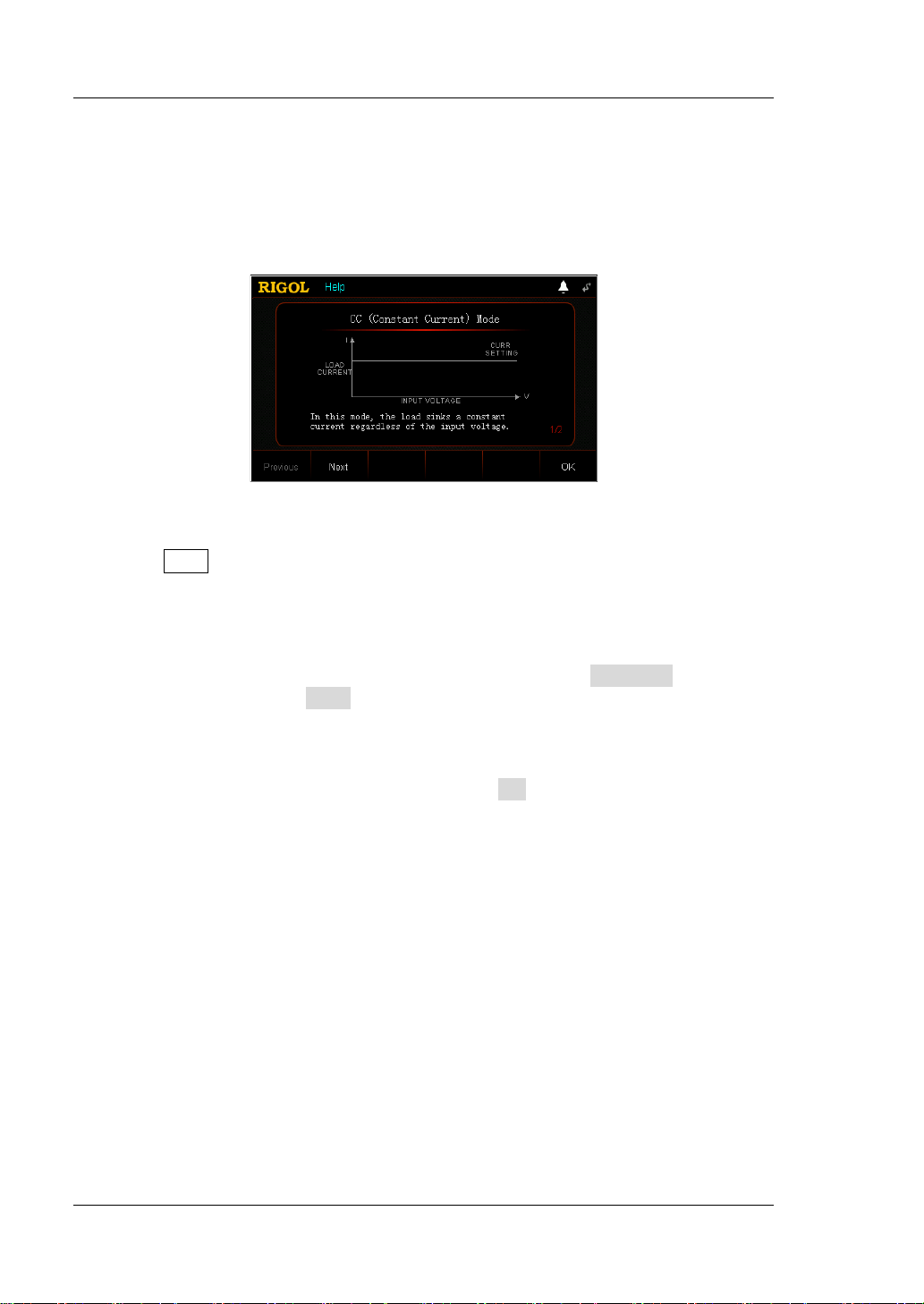
Constant Current (CC) Mode ............................................................ 2-3
Constant Voltage (CV) Mode ............................................................ 2-7
Constant Resistance (CR) Mode ....................................................... 2-11
Constant Power (CP) Mode ............................................................. 2-14
Transient Test Function ......................................................................... 2-17
CC Continuous Mode (Con) ............................................................. 2-17
CC Pulsed Mode (Pul) ..................................................................... 2-24
CC Toggled Mode (Tog) .................................................................. 2-31
List Operation Function (List) ................................................................. 2-37
Application Function ............................................................................. 2-44
OCP Test Function .......................................................................... 2-44
OPP Test Function .......................................................................... 2-52
Battery Test Function ..................................................................... 2-59
Advanced Function ............................................................................... 2-64
Factory Te st F unc tion ..................................................................... 2-64
CC+CV Function ............................................................................ 2-68
DL3000 User’s Guide IX
Page 12

RIGOL Contents
Waveform Display Function ................................................................... 2-72
Input Control ....................................................................................... 2-76
Turn On/Off the Input .................................................................... 2-76
Von Latch Function ........................................................................ 2-76
Short-circuit Operation ................................................................... 2-77
Trigger Operation .......................................................................... 2-78
Protection Function .............................................................................. 2-80
Sense Working Mode ............................................................................ 2-82
Function of Terminals on the Rear Panel ................................................. 2-84
Store and Recall ................................................................................... 2-85
Cursor .......................................................................................... 2-86
Save ............................................................................................. 2-86
Read ............................................................................................ 2-88
Delete .......................................................................................... 2-89
Copy and Paste ............................................................................. 2-89
System Utility Function ......................................................................... 2-90
System ......................................................................................... 2-91
Communication Interface Setting .................................................... 2-95
System Info ................................................................................ 2-103
Reset.......................................................................................... 2-103
Option Configuration .................................................................... 2-108
Chapter 3 Remote Control ................................................................. 3-1
Remote Control via USB .......................................................................... 3-2
Remote Control via LAN .......................................................................... 3-5
Remote Control via GPIB ......................................................................... 3-8
Remote Control via RS232 .................................................................... 3-11
Chapter 4 Troubleshooting ................................................................ 4-1
Chapter 5 Specifications .................................................................... 5-1
Chapter 6 Appendix ........................................................................... 6-1
Appendix A: Order Information ................................................................ 6-1
Append i x B: Warranty ............................................................................. 6-4
Index ........................................................................................................ 1
X DL3000 User’s Guide
Page 13

Chapter 1 Quick Start RIGOL
Chapter 1 Quick Start
Contents in this chapter:
General Inspection
Appearance and Dime nsions
Front Panel
Rear Panel
Turn-on Checkout
Fuse Replacement
User Interface
To Use the Built-in Help System
Parameter Setting Method
DL3000 User’s Guide 1-1
Page 14

RIGOL Chapter 1 Quick Start
General Inspection
1. Inspect the packaging
If the packa gi ng has be en da m age d, do n ot dis po se t he da m age d pac ka gin g o r
cushioning materials until the shipment has been che cked for completeness an d
has passed both electrical and mechanical tests.
The consigner or carrier shall be liable for the damage to the instrument
resulting from shipment. RIGOL would not be responsible for free
maintenance/rework or replacement of the instrument.
2. Inspect the instrument
In case of any mechanical damage, missing parts, or failure in passing the
electrical and mechanical tests, contact your RIGOL sales representative.
3. Check the accessories
Please check the accessories according to the packing lists. If the accessories
are damaged or incomplet e , pl e a s e contact your RIGOL sales representative.
1-2 DL3000 User’s Guide
Page 15
Chapter 1 Quick Start RIGOL
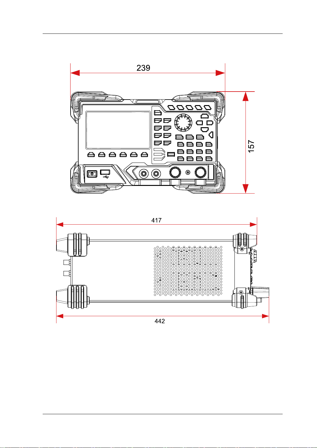
Appearance and Dimensions
Figure 1-1 Front View Unit: mm
Figure 1-2 Side View Unit: mm
DL3000 User’s Guide 1-3
Page 16
RIGOL Chapter 1 Quick Start
Pressing this key can enter the constant voltage (CV) mode. You
7
1 2 3 4 5 6
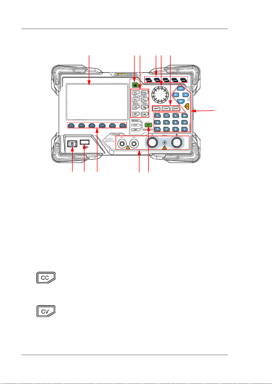
Front Panel
12 11 10 9 8
Figure 1-3 Front Panel
1. LCD
4.3-inch TFT LCD, used to display the system status, input parameters, menu
setting, prompt message, etc.
2. Waveform Display Key
Pressing this key can ent er the w a vef orm displa y int erface . You can obse rve t he
change s of parameters from the dynamic wavefo r m.
3. Function Keys
Provide four static operating modes and three dynamic test functions. In
addition, there is also a key used for list operation.
(1) CC key
Pressing this key can enter the constant current (CC) mode. You
can set parameters for the mode, such as current, range, slew
rate, and starting voltage.
(2) CV key
can set parameters for the mode, such as voltage and range.
1-4 DL3000 User’s Guide
Page 17
Chapter 1 Quick Start RIGOL
range.
Pressing this key can enter the continuous (Con) mode. You can
Pressing this key can enter the pulsed (Pul) mode. You can set
Pressing this key can enter the list operation interface. You can
is cycled
In remote operation mode, when you press this key, you can
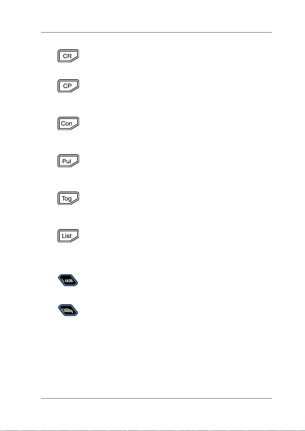
(3) CR key
Pressing this key can enter the constant resistance (CR) mode.
You can set parameters for the mode, such as resistance and
(4) CP key
Pressing this key can enter the constant power (CP) mode. You
can set param eters for the mod e , s uch as power and upp e r limit
of the voltage.
(5) Co n key
set parameters for the mode, such as range, Level A, Level B,
rising slew rate, and falling slew rate.
(6) Pul key
parameters for the mode, such as range, Level A, Level B, rising
slew rate, and falling slew rate.
(7) Tog key
Pressing this key can enter the toggled (Tog) mode. You can set
parameters for the mode, such as range, Level A, Level B, rising
slew rate, and falling slew rate.
(8) List ke y
set parameters such as mode, range, the number of times the list
, and the number of steps.
4. System Function Keys
(1) Local/remote switch key
switch to the local mode.
(2) System utility function key
System
Sets the system language, power-on value, brightness,
short-circuit function, digital input/output, beeper (on/off),
Sense function, log, Von Latch function, voltage monitoring
output terminal, and current monitoring output terminal.
Interface
Configures para met ers f or rem ot e commu n icat io n in te rface s
(GPIB/USB/RS232/LAN)
.
DL3000 User’s Guide 1-5
Page 18
RIGOL Chapter 1 Quick Start
System Info
hardware versions, FPGA version, boo t version, sys t e m boot
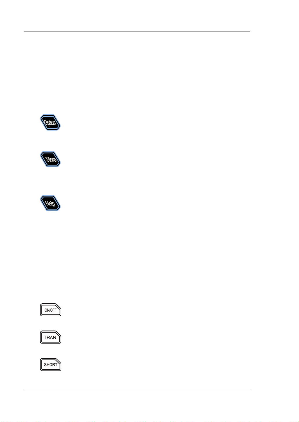
Provides advanced fun ctions. Currently, the factory test function
Saves, reads, deletes, copies, and pastes the files. The
Enters the built-in help system. You can view relevant help
Displays the manufacturer, device model, software and
times, calibration date, and product serial number.
Reset
Restores the instrument settings to its factory default
settings, For default settings, refer to Table 2-3.
(3) Advanced function key
and CC+CV function are supported.
(4) Storing and recalling operation key
instrument provides an internal non-volatil e memo ry ("Disk C")
and supports an external memory ("Disk D"). A maximum of 100
files can be stored in the instrument.
(5) Help key
information for any key or menu key on the front panel.
5. Knob
(1) Switch the parameters or parameter values.
(2) Increases (rotate clockwise) or decreases (rotate counterclockwise) the
value at the cursor.
Note: Rotating the knob in different interfaces can produce different operation
results. Here introduces its common usage. For other specific usages and
operation methods, refer to details in relevant chapters.
6. Input Control Keys
(1) Input on/off key
Enables or disables the sink function of the load.
(2) Transient trigger key
Turns on or off the transient trigger function.
(3) Short-circuit key
Enables or disables the short circuit function of the load.
1-6 DL3000 User’s Guide
Page 19
Chapter 1 Quick Start RIGOL
Switch the parameter focus.
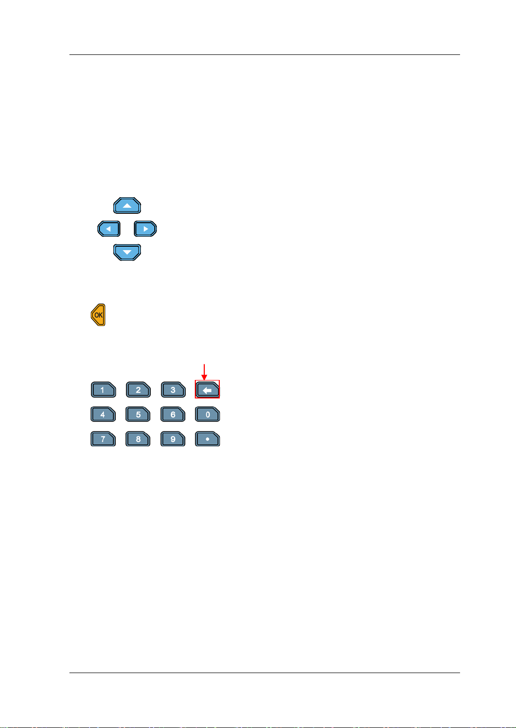
7. Control Keys
Control keys include the arrow keys, numeric keys, and confirmation key.
Pressing the control keys in different interfaces can produce different operation
results.
Note: Here introdu ces t heir com mon usa ge. F o r the ir other specific usages an d
operation methods, refer to details in relevant chapters.
(1) Arrow keys (Up/Down/Left/Right arrow key)
M ove t h e cu rsor.
Switch th e parameters or parameter values.
When setting parameters, use the Up arrow key to
increase the value at the cursor or use the Down
arrow key to decrease the value at the cursor.
(2) Confirmation key
Confirms the parameter setting.
(3) Numeric k eys and backspace k ey
Backspace key
Numeric k eys
The numeric keys contain numbers (0-9)
and a decimal point. You can use the
numeric keys to enter a value for the
parameter.
Backsp ace key
Deletes the unwanted characters or
numerical values that have been entered.
8. Application Key
Enables one of the following three application functions: OCP test, OPP test, or
Battery test. You can press this key to switch among the three functions.
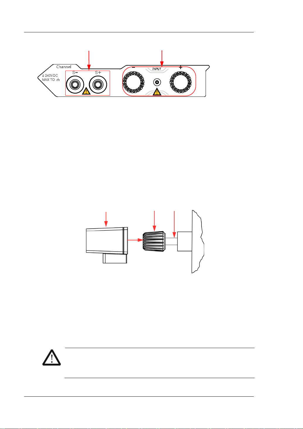
9. Channel Terminals
Channel terminals include the channel input terminals and Sense terminals, as
shown in Figure 1-4.
DL3000 User’s Guide 1-7
Page 20
RIGOL Chapter 1 Quick Start
Channel Input Terminals
Sense Terminals
Shield
Figure 1-4 Channel Terminals
(1) Channel input terminal: Connects with the device under test (DUT, such as
battery and power su ppl y), w hic h is used for in putting voltage and current.
Note: Connect the positive polarity of the load to the (+) terminal of the
channel output, and the negative polarity of the load to the (-) terminal of
the channel output.
(2) Sense terminal: When the DUT outputs large current, the sense terminal
can be used to accurately measure the voltage across the output terminals
of the DUT to compensate for the voltage drop on the load.
Connection methods for the input terminals (see Figure 1-5):
Outer Nut
A
a) Rotate the outer nut of the in put t erminal counte rclo ckwise to remo ve it.
b) Connect the test lead to Position A of the input terminal.
c) Fasten the outer nut of the input terminal clockwise.
d) Secure the shield to the terminal and then tighten the screw.
1-8 DL3000 User’s Guide
Figure 1-5 Connect Input Terminals
CAUTION
To avoid electric s ho c k , ensure that you have installed the shield
when the DC voltage output from the DUT is equal to or greater
than 70 V.
Page 21

Chapter 1 Quick Start RIGOL
10. Menu Keys
You can press the specified menu key to execute the corresponding operation
displayed at the bottom of the interface on the screen.
11. USB Host
(1) The instrument is regarded as the " master device". Y ou can use the data line
to con nect it to t he USB storage device (e.g. U-d isk) to realize external
storage or recalling.
(2) Us e the USB-GPIB interface converter to extend the GPIB interface for the
load, and then use the GPIB cable to connect the load to the PC to realize
remote contr ol .
12. Power Key
Turn on or off the instrument.
DL3000 User’s Guide 1-9
Page 22
RIGOL Chapter 1 Quick Start
4
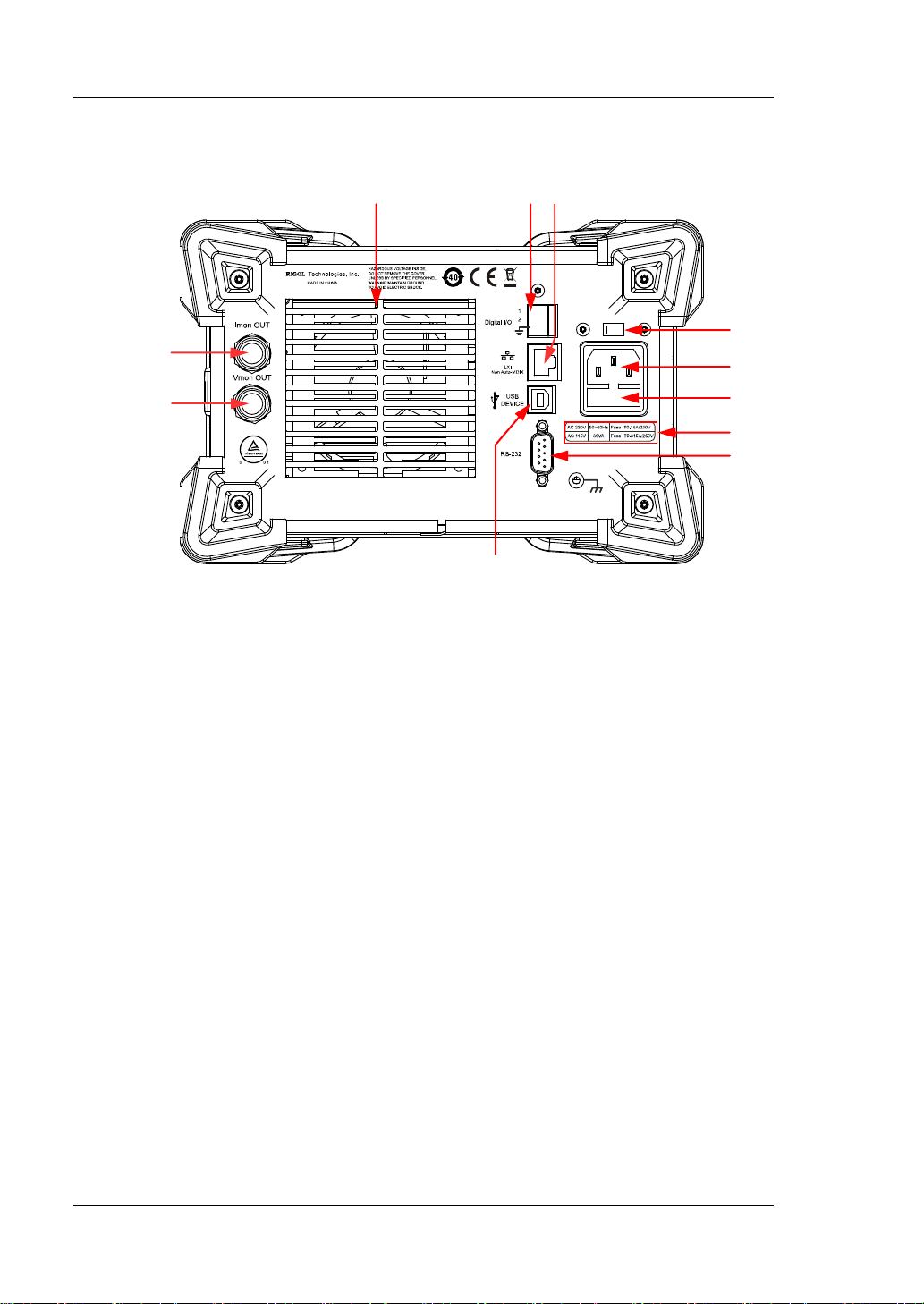
Rear Panel
1 2 3
11
10
Figure 1-6 Rear Panel
9
5
6
7
8
1. Air Outlet
Decrease the temperature inside the instrument to ensure its performance.
When you place the instru ment on the wo rkbench or install it i nto the ra ck, kee p
the air outlet from a distance of 10 cm to ensure adequate ventilation.
2. Digital I/O
A digital I/O interface, supporting trigger input and trigger output.
3. LAN Interface
LAN interface is of the Non-Auto-MDIX type. The instrument can be connecte d
to the Local Area Network (LAN) via the interface, so that you can realize remote
control for the instrument. The instrument is in compliance with the standards
specified in LXI Device Sp ecification 2011. It can be used to set up a test syste m
with other standard devices to easily realize the system integration.
4. AC Selector
Selects the voltage that matches with the actual AC input power. For details,
refer to "Fuse Rating" on the rear panel or Table 1-2.
The electronic load supports two AC voltage ratings: 115 V and 230 V.
Please
select the proper voltage scale based on the AC rating in your country.
1-10 DL3000 User’s Guide
Page 23
Chapter 1 Quick Start RIGOL
CAUTION
and ensure that no short circuit occurs to the fuse holder.
When the switch lever is located at a different position, it indicates that a
different voltage rating is selected. When the switch lever is at the left, it
indicates that 230 V is se lected. When the switch lev er is at t he right, it in dicates
that 115 V is selected.
5. AC Power Cord Connector
AC power input interface. Plug the specified power cord available in the
accessories into the AC power cord connector of the instrument, and then
connect the instrument to the AC power.
Before connecting the AC power, please select the proper voltage
scale by using the AC selector.
6. Fuse
When leaving the factory, the instrument has installed a fuse that conforms to
the local standard. For fuse replacement, refer to "Fuse Replacement".
CAUTION
To avoid electric sho ck or fire disaster , please use th e s pecified fuse
7. Fuse Rating
The required fuse rating is related to t he actual in put voltage, please refer to the
"fuse rating" on the rear panel of the load or refer to Table 1-2.
8. RS232 Interface
Serial communication interface. Use the 9-pin RS232 cable to build
communication with the PC to realize remote contro l.
9. USB Device
The instrument can be regarded as the "standby device" to connect to the
external USB dev ice (e.g. PC) to rea l ize remote control.
10. Voltage Monitorin g Output Terminal
The voltage monitoring output terminal outputs the signal in analog quantity.
You can connect a device such as a digital oscilloscope through the terminal to
display the voltage output from the output terminal, so as to monitor the
changes of input voltage of the load.
11. Current Monitoring Output Terminal
The current monitoring output terminal outputs the signal in analog quantity.
You can connect a device such as a digital oscilloscope through the terminal to
display the current output from the output terminal, so as to monitor the
changes of input current of the load.
DL3000 User’s Guide 1-11
Page 24
RIGOL Chapter 1 Quick Start
AC Input Power
AC Selector
±(10% of AC input + 115 Vac), 50 Hz to 60 Hz
115
±(10% of AC input + 230 V ac) (max: 250 Vac), 50 H z to 60 H z
230
WARNING
Turn-on Checkout
To Connect to Power Supply
Two kinds of AC power inputs are supported by the DL3000 series. When it is
connected to different power sources, the AC selector setting on its rear panel is
different, as shown in Table 1-1.
Table 1-1 AC Input Power Specification and AC Selector Setting
Please strictly follow the steps below to connect the DL3000 electronic load to the
power supply.
1. Check the input power
Ensure that the AC power to be connected to t he load conforms to the AC input
power requirement specified in Table 1-1.
2. Check the AC selector
Ensure that the AC selector setting (115 V or 230 V) on the rear panel of the load
matches the actual AC input power (For the match relationship, refer to Table
1-1).
3. Check the fuse
When leaving the factory, the load has installed a fuse that conforms to the
destination country standard. Please ref er to the "fuse rating" on the rear panel
of the load or refer to Table 1-2 to ensure that the fuse matches the actual AC
input power.
4. Connect the AC power
Plug the specified power cord available in the accessories into the AC power
supply connector of the instrument, and then connect the instrument to the
properly grounded AC power.
To avoid electric shock, ensure that the instrument is correctly
grounded.
1-12 DL3000 User’s Guide
Page 25
Chapter 1 Quick Start RIGOL
CAUTION
Tip
After powerin g off t he elect ronic l oad, plea se wai t for at leas t 1 s bef ore you power
To Power On the Instrument
After the instrument is con nected t o the power sour ce, press the Power key
the left bottom of the front panel to power on the instrument. When the instrument
is turned on, it will undergo a self-test. If the instrument passes the self-test, the
welcome interface is displayed; otherwise, self-test failure informat ion will be
displayed. At this time, please contact RIGOL distributors.
Ensure that the AC selecto r setting on the rear panel of the instrument
matches the actual AC input voltage , otherwise, the electronic load will
be burned out.
CAUTION
Please pay attention to the positive and negative polarities of the
electronic load to avoid wrong connection. Otherwise, the load will be
burned out.
at
it on again.
DL3000 User’s Guide 1-13
Page 26
RIGOL Chapter 1 Quick Start
Input Voltage
Fuse Rating
115 Vac
T0.315 A/250 V
230 Vac
T0.20 A/250 V
WARNING
To avoid personal injuries, turn off the instrument and cut off t he power
supply before replacing the fuse; to avoid electric shock or fire disaster,
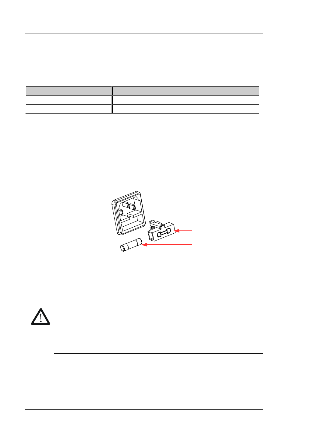
Fuse Replacement
The fuse specification is related to the actual input voltage, as shown in Table 1-2.
Table 1-2 Fuse Rating
When leaving the factory, the instrument has installed a fuse that conforms to the
local standard. If the fuse is required to be replaced, select a fuse that matches the
actual input voltage and perform the following steps.
1. Turn off the instrument, and then disconnect the instrument from the power
source. Re move the power cord.
2. Insert a slotted screwdriver into the slot of the fuse holder to pry it out, as
shown in Figure 1-7.
Fuse Holder
Fuse
Figure 1-7 Fuse Replacement
3. Take out the fuse and replace it according to the fuse rating (refer to the "Fuse
Rating" on the rear panel of the instrument or Table 1-2).
4. Mount the fuse holder (pay attention to its direction when mounting it).
before connecting to the AC power, select the voltage specification that
matches the actual input voltage and replace a proper fuse that
conforms to the voltage specif ication.
1-14 DL3000 User’s Guide
Page 27
Chapter 1 Quick Start RIGOL
No.
Name
Description
RIGOL
to select the specified menu item.
5
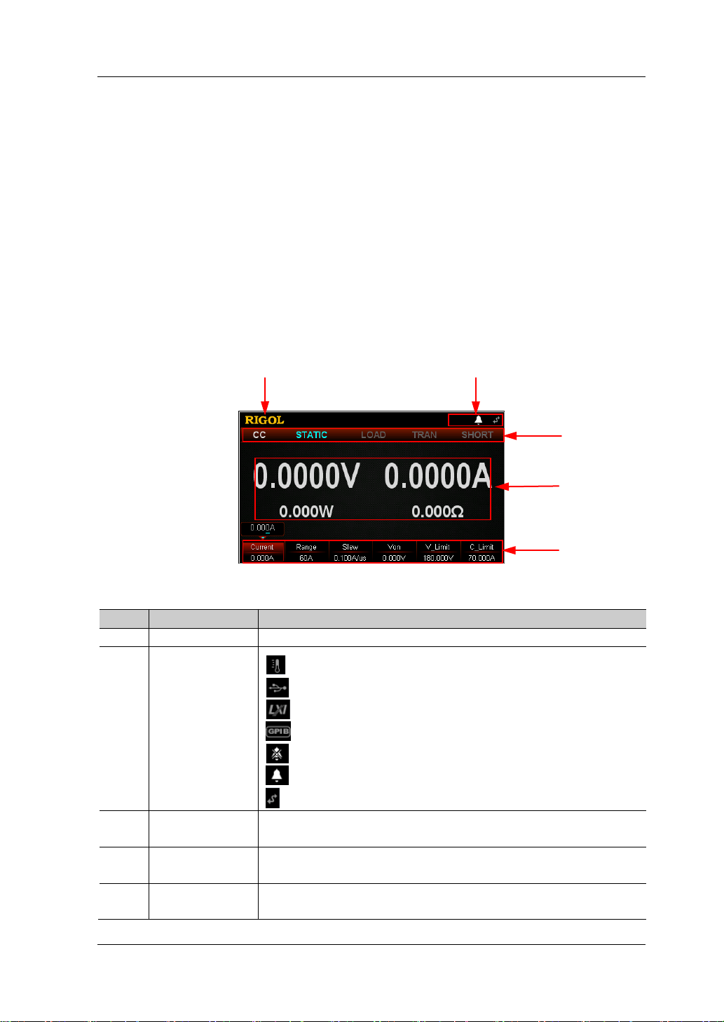
User Interface
The user interface of the DL3000 series consists of main interface, guide interface,
and function interface. In the main interface, you can set and view the information
about the channel input; in the guide interface , you can directly set the parameters
according to the guide diagram and view the parameter information; in the function
interface (including the waveform interface), you can set and view the information
about the functions. When the instru ment powers on , it e nters t he main interf ace by
default. This section mainly introduces the main interface of the electronic load. The
guide interface and function interface will be introduced in "Front Panel
Operations".
The main interface is sh own in Figure 1-8. For the des criptions of the main inte rface,
refer to Table 1-3.
1
2
3
Table 1-3 Main Interface Description
Figure 1-8 Main Interface
1
Company Logo
: indicates that the overtemperature protection occurs.
: indicates that the USB device is recognized.
: indicates that the network is connected.
: indicates that GPIB is connected.
2
System Status
Icon
: indicates that the beeper is off.
: indicates that the beeper is on.
: indicates that the instrument is remotely controlled.
3 Function State
4
Actual Input
Value
5 Menu Item
Displays the function state of the load in a real-time
manner.
Displays the actual input voltage, sink current, etc.
Displays the function menu. Press the specified key below
4
DL3000 User’s Guide 1-15
Page 28
RIGOL Chapter 1 Quick Start
To Use the Built-in Help System
The built-in help system provides help information for any key on the front panel
(except parameter input ar ea) and menu keys, which are convenient for you to get
the descriptions of the function keys or menus, as shown in Figure 1-9.
Figure 1-9 Help Information Interf ace
1. Get the built-in help information
Press Help, and then "Help" will be displayed at the top of the interface, being
highlighted. At this time, press the corresponding function key or menu key to
enter the corresponding help information interface.
2. Page up/down opera tion
If the help info rmation is displa yed in seve ral pa ges, press Previous to go to the
previous page or press Next to go to the next page. You can also use the a rrow
keys or the knob to page up/down the help information.
3. Exit the current help information interface
When the help information is displayed, press OK to exit the current help
information interface and return to the previous interface.
1-16 DL3000 User’s Guide
Page 29
Chapter 1 Quick Start RIGOL
Parameter Setting Method
Most parameters can be set by operating the keys on the front panel. The common
setting methods are listed below. The setting method for certain parameters is
different from the methods below, refer to the relevant chapters of this manual for
the further explanation.
Method 1: Use the numeric keys
1. In the main interface, press the specified menu key to switch the parameter
focus; in the guide int erf ace, use the arrow ke ys t o switch the parameter f ocus.
2. Enter a value by using the numeric key. While entering a name, press
delete the unwanted character if necessary.
3. When setting resistance, press the specified menu key and select "Ω" or "kΩ" to
be the unit.
When setting period/width, press the specified menu key and select "ms" or "s"
to be the unit.
When setting frequency, press the specified menu key and select "Hz" or "kHz"
to be the unit.
When setting other parameters, press OK to confirm the input.
Method 2: Use the knob or the arrow keys
1. In the main interface, press the specified menu key to switch the parameter
focus.
2. Press the Left/Right arrow key to move the cursor to a desired position.
3. Press the Up/D ow n arrow key or rot ate the knob to modify the value.
to
DL3000 User’s Guide 1-17
Page 30

Page 31

Chapter 2 Front Panel Operations RIGOL
Chapter 2 Front Panel Operations
Contents in this chapter:
Local/Remote Operation Mode
Static Operation Mode
Transient Test Function
List Oper ation Function (List)
Application Function
Advanced Function
Waveform Display Function
Input Control
Protection Function
Sense Working Mode
Function of Terminals on the Rear Panel
Store and Recall
System Utility Function
DL3000 User’s Guide 2-1
Page 32
RIGOL Chapter 2 Front Panel Operations
Tip
Local/Remote Operation Mode
The load provides two operation modes: local and remote.
Local Operation M ode
After you power on the instrument, it ent ers the l o c al ope ration mode by defau l t . In
the local operation mode, all the keys on the front p anel a re a v aila ble fo r y ou to use.
Remote Operation Mode
In the remote operation mode, you can send the programming commands from the
PC via any one of the interfaces (GPIB, USB, RS232, or LAN).
In remote operation mode, all the keys (except the Power key
key) were disabled. You can only control the load by progr a m ming commands. To
return to the lo cal operation mo de , press Local on the front panel.
and the Local
Factory test mode and APP functions (OCP/OPP) do not sup port re mote ope rat ion.
2-2 DL3000 User’s Guide
Page 33
Chapter 2 Front Panel Operations RIGOL
the instrument or the DUT.
- +
DUT
Static Operation Mode
The static operation modes include the following 4 modes:
Constant Current (CC) Mode
Constant Voltage (CV) Mode
Constant Resistance (CR) Mode
Constant Power (CP) Mode
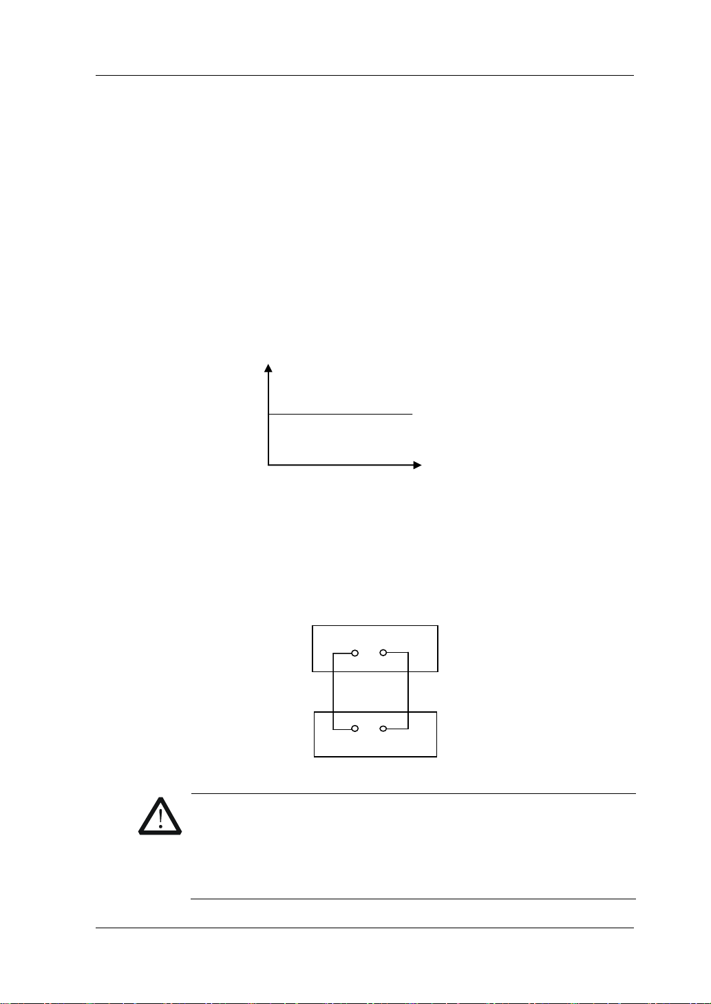
Constant Current (CC) Mode
In CC mode, the electronic load will sink a current in accordance with the
programmed value regardless of the input voltage, as shown in Figure 2-1.
Load Current
Operation Procedures:
1. Connect the DUT and the channel input terminals of the load
Turn off the instrument, as shown in Figure 2-2, connect the DUT and the
channel input terminals on the front panel of the load.
CAUTION
While making a connection, the positive polarity of the load should
be connected to the (+) terminal of the channel output, and the
negative polarity of the load to the (-) terminal of the channel
output. A misconnection with the terminals may cause damage to
I
Set Current
Input Voltage
V
Figure 2-1 Constant Cu rrent (CC) Mode
=
Front Panel
- +
Figure 2-2 Connect to the Terminals
DL3000 User’s Guide 2-3
Page 34
RIGOL Chapter 2 Front Panel Operations
Tip
2. Power on the instrument
After the instrument is connected to the power source, press th e Power key
on the front panel to power on the instrument.
3. Set channel parameters
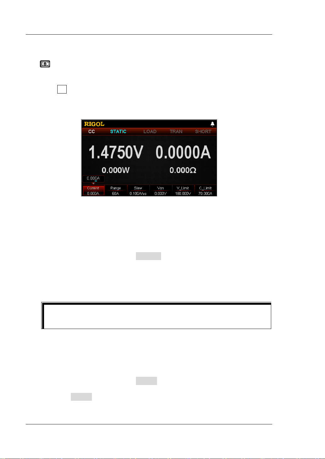
Press CC to enter the mai n interfa ce of CC mode, as s hown in Figure 2-3
. At the
top of the main interface, "CC" and "STATIC" are active. Of which, "STATIC" is
highlighted.
Figure 2-3 Main Interface of CC Mode
In CC mode, you need to set the following parameters: Current, Range, Slew,
Von, V_Limit, C_Limit.
Set Current
The constant current value in CC mode. The default unit for the current is A.
(1) In the main interface, press Current to switch the parameter focus to
"Current".
(2) Enter a value by using the numeric keys, arrow keys, or the knob. For
setting methods, refer to the descriptions of the help information or refer to
the descriptions in "Par a m e te r Setting Me th o d ".
In CC mode, when the set load current is greater than the current output
from the DUT, short circuit occurs to the DUT.
Set Range
The working ranges of current in CC mo de are as f oll ows. Diffe rent mo dels hav e
different ranges.
DL3021/DL3021A: low range (0 to 4 A); high range (0 to 40 A)
DL3031/DL3031A: low range (0 to 6 A); high range (0 to 60 A)
(1) In the main interface, press Range to switch the parameter focus to
"Range".
(2) Press Range to switch the current working range. You can also use the
Left/Right arrow key or the knob to switch it.
2-4 DL3000 User’s Guide
Page 35
Chapter 2 Front Panel Operations RIGOL
Tip
Note:
The low range provides better resolution and accuracy at low current
settings.
If the set current value is greater than t he maximum value of t he low range,
you must select a high range.
CAUTION
Before switching the current range, please disa ble th e channel input
to avoid causing damage to the instrument or the DUT.
Set Slew
The current slew rate for the positive transitions in CC mode. The slew rate
refers to the rate at which the input current to a module changes to a new
programmed value. The default unit for the slew rate is A/μs.
(1) In the main interface, press Slew to switch the parameter focus to "Slew".
(2) Enter a value by using the numeric keys, arrow keys, or the knob. For
setting methods, refer t o the descriptions of the help inf ormation or refer to
the descriptions in "Par a m e te r Setting Me th o d ".
The range of the slew rate is determined by the current ratio (from 10% to
90%; from 90% to 10%) changes.
Set Von
When the input voltage is greater than the set starting voltage (Von), the load
starts to sink the cu rrent. T he def ault unit for Von is V, and it ranges from 0 V to
150 V. The default Von is 0 V.
(1) In the main interface, press Von to switch the parameter focus to "Von".
(2) Enter a value by using the numeric keys, arrow keys, or the knob. For
setting methods, refer to the descriptions of the help informat ion or refe r to
the descriptions in "Par a m e te r Setting Me th o d ".
Set V_Limit
The upper limit of the voltage working in CC mode. The default unit for V_Limit
is V, and it ranges from 0 V to 18 0 V.
(1) In the main interface, press V_Limit to switch the parameter focus to
"V_Limit".
(2) Enter a value by using the numeric keys, ar row keys, or the knob. For sett ing
methods, refer to the descriptions of the help information or refer to the
descriptions in "Parameter Setting Method".
Set C_Limit
The upper limit of the current working in CC mode. The default unit for C_Limit
is A, and it ranges from 0 A to 70 A.
(1) In the main interface, press C_Limit to switch the parameter focus to
DL3000 User’s Guide 2-5
Page 36
RIGOL Chapter 2 Front Panel Operations
WARNING
input.
CAUTION
"C_Limit".
(2) Enter a value by using the numeric keys, arrow keys, or the knob. For
setting methods, refer to t he descriptions of the hel p information or ref er to
the descriptions in "Par a m e te r Setting Me th o d ".
4. Turn on the channel input
Press On/Off to turn on the channel input. At this time, the actual input
voltage, current, resistance, and power will be displayed in the main interface.
Note: Once the channel input is turned on, the load will not start to sink the
current until the input voltage is greater than the starting voltage.
To avoid electric shock, ensure that the DUT is connected to the
input terminals of the load properly before you turn on the channel
When the fan stops working, the channel is disabled. Then, a
message is displayed, "Fan stops running!"
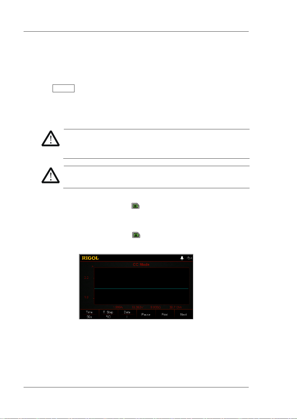
5. View waveform display
Press the waveform display key
to enter the wa vef orm displa y interfa ce ,
as shown in Figure 2-4. By default, the current wa veform is displayed . When the
input voltage changes, the load will sink a constant current. For detailed
operations, refer to the de scriptions in "Wav eform Dis play Func tion" section.
Press the waveform display key
again to exit the waveform display
interface and return to the main interface of CC mode.
6. Exit CC mode
2-6 DL3000 User’s Guide
Figure 2-4 Wa veform Display Interface of C C Mode
Press any key on the front panel of the load to exit CC mode.
Page 37

Chapter 2 Front Panel Operations RIGOL
Input Voltage
Set Voltage
Constant Voltage (CV) Mode
In CV mode, the load will s ink enough current to control the in put voltage to the set
value. The load acts as a shunt voltage regulator when operating in CV mode, as
shown in Figure 2-5.
Operation Procedures:
1. Connect the DUT and the channel input terminals of the load
Turn off the instrument, as shown in Figure 2-2, connect the DUT and the
channel input terminals on the front panel of the load.
CAUTION
While making a connection, the positive polarity of the load should
be connected to the (+) terminal of the channel output, and the
negative polarity of the load to the (-) terminal of the channel
output. A misconnection with the terminals may cause damage to
the instrument or the DUT.
2. Power on the instrument
After the instrument is connected to the power source, press the Power key
on the front panel to power on the instrument.
3. Set channel parameters
Press CV to enter the main i nterfa ce of CV mode , as sh own in Figure 2-6
top of the main interface, "CV" and "STATIC" are active. Of which, "STATIC" is
highlighted.
V
Load Current
I
Figure 2-5 Constant Voltage (CV) Mode
. At the
DL3000 User’s Guide 2-7
Page 38

RIGOL Chapter 2 Front Panel Operations
CAUTION
Tip
broken circuit
Figure 2-6 Main Interface of CV Mode
In CV mode, you need to s et the followin g parameters: V oltage, Range, V_Limit,
C_Limit.
Set Voltage
The constant voltage value in CV mode. The default unit for the voltage is V.
(1) In the main interface, press Voltage to switch the parameter focus to
"Voltage".
(2) Enter a value by using the numeric keys, arrow keys, or the knob. For the
setting methods, refer t o t he des criptions of the b uilt -in hel p inf ormatio n or
refer to the descriptions in "P ar ameter Set t in g Method".
In CV mode, when the set load voltage is greater than the voltage output
from the DUT,
occurs to the DUT.
Set Range
Working r ange for the voltage in C V mode . Two ranges are available: low range
(0-15 V) and high ra nge (0-150 V).
(1) In the main interface, press Range to switch the parameter focus to
"Range".
(2) Press Range to switch the voltage working range. You can also use the
Left/Rig h t arrow key or the knob to switch it.
Note:
The low range provides better resolution and accuracy at low voltage
settings.
If the set v oltage value is greater tha n the maximum value of the low ra nge,
you must select a high range.
Before switching the v olt age range, please disable the channel input
to avoid causing damage to the instrument or the DUT.
2-8 DL3000 User’s Guide
Page 39
Chapter 2 Front Panel Operations RIGOL
CAUTION
Set V_Limit
The upper limit of the voltage working in CV mode. The default unit for V_Limit
is V, and it ranges from 0 V to 18 0 V.
(1) In the main interface, press V_Limit to switch the parameter focus to
"V_Limit".
(2) Enter a value by using the numeric keys, arrow keys, or the knob. For the
setting methods, refer t o t he des criptions of the b uilt -in hel p inf ormatio n or
refer to the descriptions in "Parameter Setting Method".
Set C_Limit
The upper limit of the current working in CV mode. The default unit for C_Limit
is A, and it ranges from 0 A to 70 A.
(1) In the main interface, press C_Limit to switch the parameter focus to
"C_Limit".
(2) Enter a value by using the numeric keys, ar row keys, or the knob. For sett ing
methods, refer to the descriptions of the help information or refer to the
descriptions in "Parameter Setting Method".
4. Turn on the channel input
Press On/Off to turn on the channel input. At this time, the actual input
voltage, current, resistance, and power will be displayed in the main interface.
WARNING
To avoid electric shock, ensure that the DUT is connected to the
input terminals of the load properly before you turn on the channel
input.
When the fan stops working, the channel is disabled. Then, a
message is displayed, "Fan stops running!"
5. View waveform display
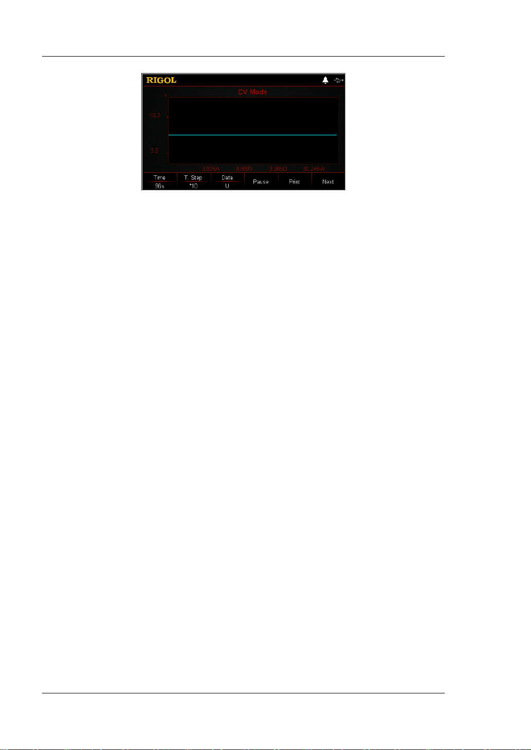
Press the waveform d isp lay k e y
to enter the w av eform display inte rface,
as shown in Figure 2-7. When you select "U" under "Data", you can view the
voltage waveform. When changes occur to the current, the input voltage
remains to be the set voltage, unchanged. For detailed operations, refer to the
descriptions in "Wave fo rm Display Function" section. Press the waveform
display key
again to exit the wav eform displa y int erface a nd retu rn to t he
main interface of CV mode.
DL3000 User’s Guide 2-9
Page 40
RIGOL Chapter 2 Front Panel Operations
Figure 2-7 Waveform Display Interface of CV Mode
6. Exit CV mode
Press any key on the front panel of the load to exit CV mode.
2-10 DL3000 User’s Guide
Page 41
Chapter 2 Front Panel Operations RIGOL
CAUTION
Input Voltage
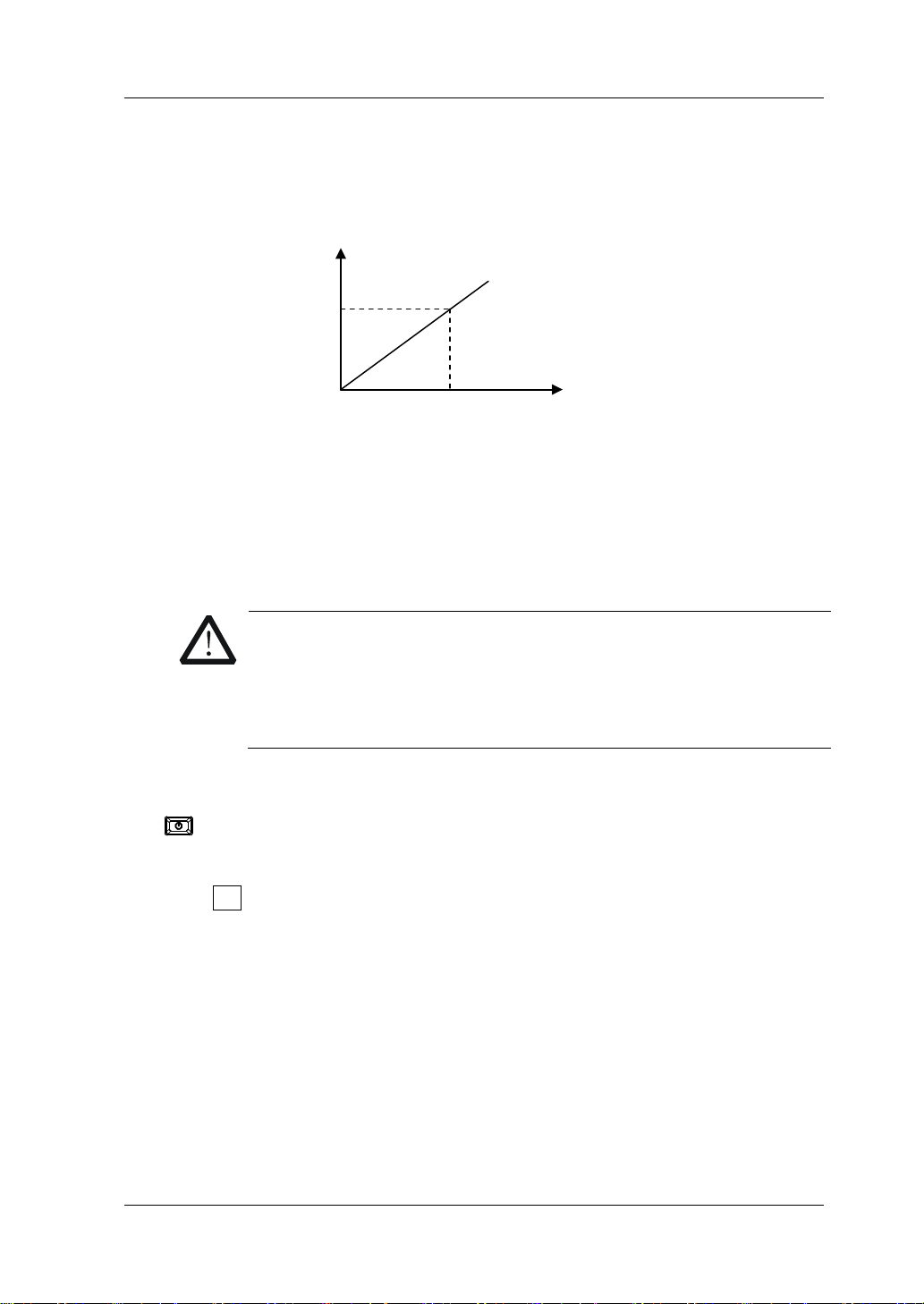
Constant Resistance (CR) Mode
In CR mode, the load is regarded as a constant resistance, and changes the curre nt
linearly proportional to the input voltage, as shown in Figure 2-8.
Load Current
Operation Procedures:
1. Connect the DUT and the channel input terminals of the load
Turn off the instrument, as shown in Figure 2-2, connect the DUT and the
channel input terminals on the front panel of the load.
I
Set Resistance
(R=V/I)
V
Figure 2-8 Constant Resistance (CR) Mode
While making a connection, the positive polarity of the load should
be connected to the (+) terminal of the channel output, and the
negative polarity of the load to the (-) terminal of the channel
output. A misconnection with the terminals may cause damage to
the instrument or the DUT.
2. Power on the instrument
After the instrument is connected to the power source, press the Power key
on the front panel to power on the instrument.
3. Set channel parameters
Press CR to enter the main interfa ce of CR mode, as shown in Figure 2-9
top of the main interface, "CR" and "STATIC" are active. Of which, "STATIC" is
highlighted.
. At the
DL3000 User’s Guide 2-11
Page 42

RIGOL Chapter 2 Front Panel Operations
CAUTION
Figure 2-9 Main Interf ace of CR Mode
In CR mode, you need to set the following parameters: RES, Range, V_Limit,
C_Limit.
Set RES
The constant resistance value in CR mode. The resistance unit is: Ω or kΩ.
(1) In the main interface, press RES to switch the parameter focus to "RES".
(2) Enter a value by using the numeric keys, arrow keys, or the knob. For
setting methods, refer to the des criptions of the help information or refer to
the descriptions in "Par a m e te r Setting Me th o d ".
Set Range
Working range for the resistance in CR mode. Two resistance ranges are
available: low range (0.08 Ω to 15 Ω); high range (2 Ω to 15 kΩ)
(1) In the main interface, press Range to switch the parameter focus to
"Range".
(2) Press Range to switch the resistance working range. You can also use the
Left/Right arrow key or the knob to switch it.
Note:
The low range provides better resolution and accuracy at low resistance
settings.
If the set resistance value is greater than the maximum value of the low
range, you must select a high ran ge.
2-12 DL3000 User’s Guide
Before switching the resistance range, please disable the channel
input to avoid causing damage to the instrument or the DUT.
Set V_Limit
The upper limit of the voltage working in CR mode. The default unit for V_Limit
is V, and it ranges from 0 V to 18 0 V.
(1) In the main interface, press V_Limit to switch the parameter focus to
"V_Limit".
(2) Enter a value by using the numeric keys, arrow keys, or the knob. For
setting methods, refer to the descriptions of the help informat ion or refer to
the descriptions in "Par a m e te r Setting Me th o d ".
Page 43

Chapter 2 Front Panel Operations RIGOL
CAUTION
Set C_Limit
The upper limit of the current working in CR mode. The default unit for C_Limit
is A, and it ranges from 0 A to 70 A.
(1) In the main interface, press C_Limit to switch the parameter focus to
"C_Limit".
(2) Enter a value by using the numeric keys, ar row keys, or the knob. For setting
methods, refer to the descriptions of the help information or refer to the
descriptions in "Parameter Setting Method".
4. Turn on the channel input
Press On/Off to turn on the channel input. At this time, the actual input
voltage, current, resistance, and power will be displayed in the main interface.
WARNING
To avoid electric shock, ensure that the DUT is connected to the
input terminals of the load properly before you turn on the channel
input.
When the fan stops working, the channel is disabled. Then, a
message is displayed, "Fan stops running!"
5. View waveform display
Press the waveform display key
to enter the wa vef orm displa y interfa ce ,
as shown in Figure 2-10. When you select "R" under "Data", you can view the
resistance waveform. When changes occur to the input voltage, the current
changes linearly to keep the resistance value unchanged. For detailed
operations, refer to the de scriptions in "Waveform Display Function" section.
Press the waveform display key
again to exit the waveform display
interface and return to the main interface of CR mode.
Figure 2-10 Wave form Display Inte rface of CR Mode
6. Exit CR mode
Press any key on the front panel of the load to exit CR mode.
DL3000 User’s Guide 2-13
Page 44

RIGOL Chapter 2 Front Panel Operations
I
I2
Constant Power (CP) Mode
The load sinks a constant power in CP mode. The load current will change linearly
proportional to the input voltage to keep sinking a constant power (P = V x I), as
shown in Figure 2-11.
Input Voltage
Operation Procedures:
1. Connect the DUT and the channel input terminals of the load
Turn off the instrument, as shown in Figure 2-2, connect the DUT and the
channel input terminals on the front panel of the load.
CAUTION
While making a connection, the positiv e pola rit y of the load should
be connected to the (+) terminal of the channel output, and the
negative polarity of the load to the (-) terminal of the channel
output. A misconnection with the terminals may cause damage to
the instrument or the DUT.
2. Power on the instrument
After the instrument is connected to the power source, press the Power key
on the front panel to power on the instrument.
3. Set channel parameters
Press CP to enter the main interface of CP mode, as shown in Figure 2-12
the top of the main interface, "CP" and "STATIC" are active. Of w hich, "STATIC"
is highlighted.
V
V1
V2
I1
Set Power
Load Current
Figure 2-11 Constant Power (CP) Mode
. At
2-14 DL3000 User’s Guide
Page 45

Chapter 2 Front Panel Operations RIGOL
Figure 2-12 Main Interface of CP Mode
In CP mode, you need t o s et t he foll owing parameters: P ower, V_Limit, C_Limit.
Set Power
The constant power value in CP mode. The default unit for power is W.
(1) In the main interface, press Power to switch the parameter focus to
"Power".
(2) Enter a value by using the numeric keys, arrow keys, or the knob. For the
setting methods, refer t o t he des criptions of the b uilt -in hel p inf ormatio n or
refer to the descriptions in "Parameter Setting Method".
Set V_Limit
The upper limit of the voltage working in CP mode. The default unit for V_Limit
is V, and it ranges from 0 V to 18 0 V.
(1) In the main interface, press V_Limit to switch the parameter focus to
"V_Limit".
(2) Enter a value by using the numeric keys, arrow keys, or the knob. For the
setting methods, refer to the descriptions of the built-in help information or
refer to the descriptions in "Parameter Setting Method".
Set C_Limit
The upper limit of the current working in CP mode. The default unit for C_Limit
is A, and it ranges from 0 A to 70 A.
(1) In the main interface, press C_Limit to switch th e parameter focus to
"C_Limit".
(2) Enter a value by using the numeric keys, arrow keys, or the knob. For the
setting methods, refer to the descriptions of the built-in help information or
refer to the descriptions in "Parameter Setting Method".
4. Turn on the channel input
Press On/Off to turn on the channel input. At this time, the actual input
voltage, current, resistance, and power will be displ ayed in the main interface.
DL3000 User’s Guide 2-15
Page 46

RIGOL Chapter 2 Front Panel Operations
WARNING
CAUTION
To avoid electric shock, ensure that the DUT is connected to the
input terminals of the load properly before you turn on the channel
input.
When the fan stops working, the channel is disabled. Then, a
message is displayed, "Fan stops running!"
5. View waveform display
Press the waveform display key
to enter the wa vef orm displa y interfa ce ,
as shown in Figure 2-13. When you select "P" under "Data", you can v i ew the
power waveform. When changes occur to the inp ut voltage, the cur rent changes
linearly to keep the power value unchan ged. For detailed operations, ref er to the
descriptions in "Wave fo rm Display Function" section. Press the waveform
display key
again to exit the waveform display interface and return to the
main interface of CP mode.
6. Exit CP mode
2-16 DL3000 User’s Guide
Figure 2-13 Wave form Display Inte rface of CP Mode
Press any key on the front panel of the load to exit CP m ode.
Page 47

Chapter 2 Front Panel Operations RIGOL
CAUTION
T
A
Transient Test Function
Transient test f uncti on ena bles the l oad to periodi cally swit ch between tw o set l ev els
(Level A and Level B). It can be used t o t est the transient cha racteristics of the DUT.
Transient oper ati on can o nly be used in CC mode and supports the following 3
operation modes:
CC continuous mode (Con)
CC pulsed mode (Pul)
CC toggled mode (Tog)
Before performing the transient operation, f irst set parameters for the transient
operation, such as Level A, Level B, frequency, duty, etc.
CC Continuous Mode (Con)
In continuous operation, when you enable the transient test, the load current will
continuously switch over between Level A and Level B, as shown in Figure 2-14.
Operation Procedures:
1. Connect the DUT and the channel input terminals of the load
Turn off the instrument, as shown in Figure 2-2, connect the DUT and the
channel input terminals on the front panel of the load.
B
Figure 2-14 CC Continuous Mode (Con)
While making a connection, the positive polarity of the load should
be connected to the (+) terminal of the channel output, and the
negative polarity of the load to the (-) terminal of the channel
output. A misconnection with the terminals may cause damage to
the instrument or the DUT.
2. Power on the instrument
After the instrument is connected to the power source, press the Power key
on the front panel to power on the instrument.
DL3000 User’s Guide 2-17
Page 48
RIGOL Chapter 2 Front Panel Operations
to avoid causing damage to the instrument or the DUT.
Parameter
3. Set channel parameters in the guide interface
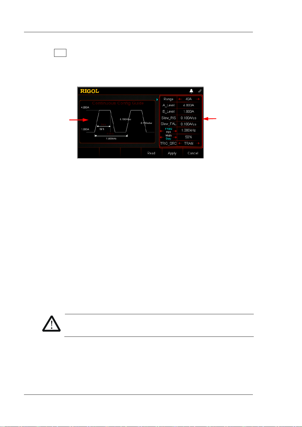
Press Con to enter the Con guide interface, as shown in Figure 2-15
. In the
guide interface, you can configure parameters in the parameter configuration
list and view the configuration diagram at the left of the configuration list in the
real-time manner.
Guide
Diagram
Configuration List
Figure 2-15 Guide Interface of Con Operation
The parameters for t he continuous operation m ode include range, Lev el A, Level
B, rising slew rate, falling slew rat e, f req uenc y/ period, width/duty, and trigger
source.
Set Range
Working range for the current in Con mode. Two ranges are available.
DL3021/DL3021A: low range (0 to 4 A); high range (0 to 40 A)
DL3031/DL3031A: low range (0 to 6 A); high range (0 to 60 A)
(1) In the guide interface, press the Up/Down arrow key to switch the
parameter focus to " Range".
(2) Use the Left/Right arrow key or the knob to switch the current working
range.
Note:
The low range provides better resolution and accuracy at low current
settings.
If the set current value is greater than t he maximum v alue of the low range,
you must select a high range.
CAUTION
Before switching the current range, please disa ble th e channel input
Set A_Level
The sink current toggles between a high value and a low value in Con mode.
A_Level indicates a high value. The default unit for A_Level is Ampere (A).
(1) In the guide interface, press the Up/Down arrow key to switch the
parameter focus to "A_Level".
2-18 DL3000 User’s Guide
Page 49

Chapter 2 Front Panel Operations RIGOL
(2) Enter a value by using the numeric keys. For setting methods, refer to the
descriptions in "Para meter Settin g Method".
Note: The input value of A_Level should be within the set range.
Set B_Level
The sink current toggles between a high value and a low value in Con mode.
B_Level indicates a low value. The default unit for B_Level is Ampere (A).
(1) In the guide interface, press the Up/Down arrow key to switch the
parameter focus to " B_Level".
(2) Enter a value by using the numeric keys. For setting methods, refer to the
descriptions in "Parameter Setting Method".
Note: The set A_Level and B_Level for a specified model should be within its
specified high and low ranges for the model.
Set Slew_RIS
Sets the sink current slew rate for the positive t ransitions f rom Level B to Level A
in Con mode. The default unit for the rising slew rate is A/μs.
(1) In the guide interface, press the Up/Down arrow key to switch the
paramete r focus to "Slew_RIS".
(2) Enter a value by using the numeric keys. For setting methods, refer to the
descriptions in "Parameter Setting Method".
Set Slew_FAL
Sets the sink current sle w rate for the negative trans it ions from Level A to Level
B in Con mode. The default unit for the falling slew rate is A/μs.
(1) In the guide interface, press the Up/Down arrow key to switch the
parameter focus to " Slew_FAL".
(2) Enter a value by using the numeric keys. For setting methods, refer to the
descriptions in "Parameter Setting Method".
Set FREQ/PER
Period: The sum of time during which the si nk current s tays at Level A and Level
B. The unit is s or ms.
Frequency: The reciprocal of period. The unit is Hz or kHz.
(1) In the guide interface, press t he Up/Do wn arrow key to switch the
parameter focus to " FREQ/PER".
(2) Enter a value by using the numeric keys. For setting methods, refer to the
descriptions in "Parameter Setting Method".
Set Width/Duty
Width: The time du ring which the sink current stays at Level A when it switches
to Level A in Con mode. Its unit is s or ms.
Duty: The ratio of duration of Level A to the period when the sink current
switches to Level A in Con mod e.
DL3000 User’s Guide 2-19
Page 50

RIGOL Chapter 2 Front Panel Operations
(1) In the guide interface, press t he Up/Do wn arrow key t o switch the
parameter focus to " Width/Duty". Then, p ress the L eft/Rig ht arrow key or
the knob to select Width or Duty.
(2) Enter a value by using the numeric keys. For setting methods, refer to the
descriptions in "Parameter Setting Method".
Set TRIG_SRC
Three triggers are available in Con mode: BUS trigger, TRAN trigger, and DIGIO
trigger.
(1) In the guide interface, press the Up/Down arrow key to switch the
parameter focus to " TRIG_SRC".
(2) Press the Left/Right arrow key or rotate the knob to select the type of the
trigger source .
4. Enter the ma in interface
In the guide interface, after y ou configure the parameters, press Apply to enter
the main interface, as shown in
Figure 2-16. At this time, the parameters are
successfully configured. "CC" and "Continuous" are activ e at the top of the main
interface. "Continuous" is highlighted. In the guide interface, if you give up
configuring parameters , you can press Cancel to exit the guide interface and
enter the main interface.
Figure 2-16 Main Interface of Con Operation
The menus of the main interfac e ar e displayed in three pages.
Menu ite ms on Page 1: Range, A_Level, B_Level, PER/FREQ, Duty/Width, and
Next.
Menu items on Pa ge 2: Sle w_RIS, Slew_FAL, TRIG_SRC, Guide, Next, and Back.
Menu items on Page 3: Read, Save, and Back.
To go to t he next page, p r es s Next; to exit the current page and go back to the
previous page, press Back; to go back to the guide interface from the main
interface, press Guide.
In the main interface, you can also set parameters based on your own needs.
The setting methods for the parameters are as follows:
2-20 DL3000 User’s Guide
Page 51

Chapter 2 Front Panel Operations RIGOL
Set Range
(1) In the main interface, press Range to switch the parameter focus to
"Range".
(2) Press Range to switch the current working range. You can also use the
Left/Right arrow key or the knob to switch it.
Set A_Level
(1) In the main interface, press A_Level to s witch th e parameter focus to
"A_Level".
(2) Enter a value by using the numeric keys, arrow keys, or the knob. For
setting methods, refer to the descriptions of the help informat ion or refer to
the descriptions in "Par a m e te r Setting Me th o d ".
Set B_Level
(1) In the main interface, press B_Level to switch the parameter focus to
"B_Level".
(2) Enter a value by using the numeric keys, arrow keys, or the knob. For
setting methods, refer to the descriptions of the help informat ion or refer to
the descriptions in "Parameter Setting Method".
Set PER/FREQ
(1) In the main interface, press PER/FREQ to switc h the parameter focus to
"PER/FREQ".
(2) Press PER/FREQ to switch between Period and Frequency.
(3) Enter a value by using the numeric keys, arrow keys, or the knob. For
setting methods, refer to the descri ptions of the help inf ormation or refe r to
the descriptions in "Par a m e te r Setting Me th o d ".
Set Duty/Width
(1) In the main interface, press Duty/Width to switch the parameter focus to
"Duty/Width".
(2) Press Duty/Width to switch between Duty and Width.
(3) Enter a value by using the numeric keys, arrow keys, or the knob. For
setting methods, refer to the descriptions of the help informat ion or refer to
the descriptions in "Par a m e te r Setting Me th o d ".
Set Slew_RIS
(1) In the main interface, press Slew_RIS to switch the parameter focus to
"Slew_RIS".
(2) Enter a value by using the numeric keys, arrow keys, or the knob. For
setting methods, refer to the descriptions of the help in format ion or re fer t o
the descriptions in "Par a m e te r Setting Me th o d ".
Set Slew_FAL
(1) In the main interface, press Slew_FAL to switch the parameter focus to
"Slew_FAL".
DL3000 User’s Guide 2-21
Page 52

RIGOL Chapter 2 Front Panel Operations
WARNING
CAUTION
Tip
arameter; in the main interface, y ou can use the numeric keys, the arrow keys , or
(2) Enter a value by using the numeric keys, arrow keys, or the knob. For
setting methods, refer to the descriptions of the help informat ion or refer to
the descriptions in "Par a m e te r Setting Me th o d ".
Set TRIG_SRC
(1) In the guide interface, press TRIG_SRC to switch the parameter focus to
"TRIG_SRC".
(2) Press TRIG_SRC to select the t y pe of the trigger source. You can also use
the Left/Right arrow key or the knob to select it.
In the guide interface, yo u can only use the numeri c keys to input the v alue for the
p
the knob to input the value for the parameter.
5. Enable trigger
After you enable the trigger, the actual input voltage, current, resistance, and
power of the load will be displayed in the main interface.
Note: In Con mode, if the trigger is always enabled, the load will run based on
the set parameters.
Tip
You can enable the trigger first and then the load in put is automatically turned
on (The load sinks the current of Level B, and then the input will be updated
according to the preset value). You can also press the ON/OFF key on the
front panel first to turn on the input before you enable the trigger (The load
sinks the current of Level B, and then waits trigger to o ccur. After the trigger is
enabled, the input will be updated according to the preset value).
After the trigger is enabled, the load current displayed in the main interface
may stay at a constant value, because it is very fast for the current to
transition from Level A to Level B. At this time, you can observe that the load
current toggles between Level A and Level B in the dynamic wa veform displa y
interface.
To avoid electric shock, ensure that the DUT is connected to the
input terminals of the load properly before you enable the trigger.
When the fan stops working, the channel is disabled. Then, a
message is displayed, "Fan stops running!"
2-22 DL3000 User’s Guide
Page 53

Chapter 2 Front Panel Operations RIGOL
6. View waveform display
After you enter the main interface, press the waveform display key
to
enter the waveform display interface, as shown in Figure 2-17. By default, the
waveform is displayed in Fast mode. You can observe that the load current
toggles continuously between Level A and Level B. For detailed operations, refer
to the descriptions in "Wa veform Display Function" section. Press the
waveform display key
again to exit the waveform display interface and
return to the main interface of Con mode.
Figure 2-17 Wave form Display Inte rface of Con Mod e
7. Save and read files
In the guide interface and main interface of Con mode, you can press Save to
save the parameters for Con mode to the internal or external memory, and you
can read a nd recall it if necessary by pressing Read.
(1) Save
After you complete the parameter setting, press Save to enter the storage
and recall interface. The file is saved in ".CON" format. For detailed saving
operation, refer to the descriptions in "
Save".
(2) Read
Press Read to enter the storage and recall interface. Recall and read the
files in ".CON" format or the ".RSF" files beginning with "CON_". For
detailed reading operation, refer to descriptions in "
Read". The files to be
recalled and read are allowed to be edited.
How to press the Store key on the front to perform the saving and reading
operation, refer to the descriptions in "Store and Recall".
8. Exit Con mode
Press any key on the front panel of the load to exit Con mode.
DL3000 User’s Guide 2-23
Page 54

RIGOL Chapter 2 Front Panel Operations
CAUTION
CC Pulsed Mode (Pul)
In the Pul mode, when you enable the transient test operation, the load current will
switch from Level B to Level A onc e the load receives a trigger signal. After
maintaining Level A for a specified pulse width, it will switch to Level B, as shown in
Figure 2-18.
A
B
TWD
TRIG
Figure 2-18 CC Pulsed Mode (Pul)
Operation Procedures:
1. Connect the DUT and the channel input terminals of the load
Turn off the instrument, as shown in Figure 2-2, connect the DUT and the
channel input terminals on the front panel of the load.
TRIG
TWD
2. Power on the instrument
3. Set channel parameters in the guide interface
While making a connection, the positive polarity of the load should
be connected to the (+) terminal of the channel output, and the
negative polarity of the load to the (-) terminal of the channel
output. A misconnection with the terminals may cause damage to
the instrument or the DUT.
After the instrument is connected to the power source, press the Power key
on the front panel to power on the instrument.
Press Pul to enter the Pul guide interface, as shown in Figure 2-19
. In the guide
interface, you can configure parameters in the parameter configuration list and
view the configuration diagram at the left of the configuration list in the
real-time manner.
2-24 DL3000 User’s Guide
Page 55
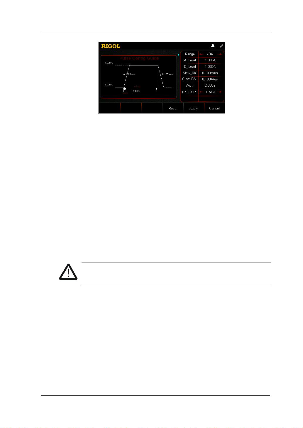
Chapter 2 Front Panel Operations RIGOL
CAUTION
Figure 2-19 Guide Interface of Pul Operation
The parameters for the pulsed operation mode include range, Level A, Level B,
rising slew rate, falling slew rate, width, and trigger source.
Set Range
The current working range in Pul mode. Two current ranges are available:
DL3021/DL3021A: low range (0 to 4 A); high range (0 to 40 A)
DL3031/DL3031A: low range (0 to 6 A); high range (0 to 60 A)
(1) In the guide interface, press the Up/Down arrow key to switch the
parameter focus to "Range".
(2) Use the Left/Right arrow key or the knob to switch the current working
range.
Note:
The low range provides better resolution and accuracy at low current
settings.
If the set current value is greater than t he maximum v alue of the low range,
you must select a high range.
Before switching the current range, please disa ble th e channel input
to avoid causing damage to the instrument or the DUT.
Set A_Level
The sink current toggles between a high value and a low value in Pul mode.
A_Level indicates a high value. The default unit for A_Level is Ampere (A).
(1) In the guide interface, press the Up/Down arrow key to switch the
parameter focus to " A_Level".
(2) Enter a value by using the numeric keys. For the setting methods, refer to
the descriptions in "Para me te r Setting Me t h od ".
Note: The input value of A_Level should be within the set range.
DL3000 User’s Guide 2-25
Page 56

RIGOL Chapter 2 Front Panel Operations
Set B_Level
The sink current toggles between a high value and a low value in Pul mode.
B_Level indica t es a low value. The default unit for B_Level is Ampere (A).
(1) In the guide interface, press the Up/Down arrow key to switch the
parameter focus to " B_Level".
(2) Enter a value by using the numeric keys. For the setting methods, refer to
the descriptions in "Par a m e te r Setting Me th o d ".
Note: The set A_Level and B_Level for a specified model should be within its
specified high and low ranges for the model.
Set Slew_RIS
Sets the sink current slew rate for the positive t ransitions f rom Level B to Level A
in Pul mode. The default unit for the rising slew rate is A/μs.
(1) In the guide interface, press the Up/Down arrow key to switch the
parameter focus to " Slew_RIS".
(2) Enter a value by using the numeric keys. For the setting methods, refer to
the descriptions in "Par a m e te r Setting Me th o d ".
Set Slew_FAL
Sets the sink current sle w rate for the negative trans iti ons from Level A to Level
B in Pul mode. The default unit for the falling slew rate is A/μs.
(1) In the guide interface, press the Up/Down arrow key to switch the
parameter focus to " Slew_FAL".
(2) Enter a value by using the numeric keys. For the setting methods, refer to
the descriptions in "Parameter Se t t in g Method".
Set Width
The time during whi ch the sink current st ays at Level A when it switches to Level
A in Pul mode. Its unit is s or ms.
(1) In the guide interface, press the Up/Down arrow key to switch the
parameter focus to " Width".
(2) Enter a value by using the numeric keys. For the setting methods, refer to
the descriptions of the built-in help information or refer to the descriptions
in "Paramete r Se t ting Method ".
Set TRIG_SRC
Three triggers are available in Pul mode : B US trigger, TRAN trigger, and DIGIO
trigger.
(1) In the guide interface, press the Up/Down arrow key to switch the
parameter focus to " TRIG_SRC".
(2) Press the Left/Right arrow key to select the type of the trigger source.
4. Enter the ma in interface
In the guide interface, after you configure the parameters, press Apply to enter
the main interface, as shown in
Figure 2-20. At this time, the parameters are
2-26 DL3000 User’s Guide
Page 57

Chapter 2 Front Panel Operations RIGOL
successfully configured. "CC" and "Pulse" are active at the top of the main
interface. Of which, "Pulse" is highlighted. In the guide interface, if you give up
configuring parameters , you can press Cancel to exit the guide interface and
enter the main interface.
Figure 2-20 Main Interface of Pul Operation
The menus of the main interfac e ar e displayed in two pages .
Menu ite ms on Page 1: Range, A_Level, B_Level, Slew_RIS, Slew_FAL, and
Next.
Menu ite ms on Page 2: Width, TRIG_SRC, Guide, Read, Save, and Back.
To go to the next page, press Next; to exit the current page and go back to the
previous page, press Back; to go back to the guide interface from the main
interface, press Guide.
In the main interface, you can also set parameters based on your own needs.
The setting methods for the parameters are as follows:
Set Range
(1) In the main interface, press Range to switch the parameter focus to
"Range".
(2) Press Range to switch the current working range. You can also use the
Left/Right arrow key or the knob to switch it.
Set A_Level
(1) In the main interface, press A_Level to switch the parameter focus to
"A_Level".
(2) Enter a value by using the numeric keys, arrow keys, or the knob. For the
setting methods, refer t o t he des criptions of the b uilt -in hel p inf ormatio n or
refer to the descriptions in "Parameter Setting Method".
Set B_Level
(1) In the main interface, press B_Level to switch the parameter focus to
"B_Level".
(2) Enter a value by using the numeric keys, arrow keys, or the knob. For
setting methods, refer to t he descriptions of the hel p information or refer to
the descriptions in "Par a m e te r Setting Me th o d ".
DL3000 User’s Guide 2-27
Page 58
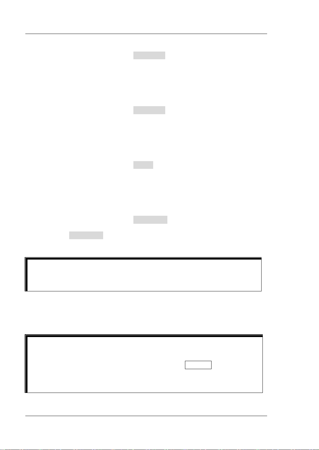
RIGOL Chapter 2 Front Panel Operations
Tip
Tip
Set Slew_RIS
(1) In the main interface, press Slew_RIS to switch the parameter focus to
"Slew_RIS".
(2) Enter a value by using the numeric keys, arrow keys, or the knob. For
setting methods, refer to the descriptions of the help informat ion or refer to
the descriptions in "Par a m e te r Setting Me th o d ".
Set Slew_FAL
(1) In the main interface, press Slew_FAL to switch the parameter focus to
"Slew_FAL".
(2) Enter a value by using the numeric keys, arrow keys, or the knob. For
setting methods, refer to the descriptions of the help informat ion or refer to
the descriptions in "Par a m e te r Setting Me th o d ".
Set Width
(1) In the main interface, press Width to switch the parameter focus to
"Width".
(2) Enter a value by using the numeric keys, arrow keys, or the knob. For
setting methods, refer to the descriptions of the help information or ref er to
the descriptions in "Parameter Set tin g Method".
Set TRIG_SRC
(1) In the main interface, press TRIG_SRC to switch the parameter focus to
"TRIG_SRC".
(2) Press TRIG_SRC to select the type of the t ri gge r source. You can also use
the Left/Right arrow key or the knob to select it.
In the guide interface, you can only use the numeric keys to input the value for
the parameter; in the main interface, you can use the numeric keys, the arrow
keys, or the knob to input the value for the parameter.
5. Enable trigger
After you enable the trigger, the actual input voltage, current, resistance, and
power of the load will be displayed in the main interface.
You can ena ble the trigger first and then the load i nput is aut omatically tur ned on
(The load sinks the current of Level B, and then the input will be updated
according to the preset value). You can also p ress the ON/OFF key on the front
panel first to turn on the input before you enable the trigger (The load sinks the
current of Level B, and then waits trigger to occur. After the trigger is enabled,
the input will be updated according to the preset value).
2-28 DL3000 User’s Guide
Page 59
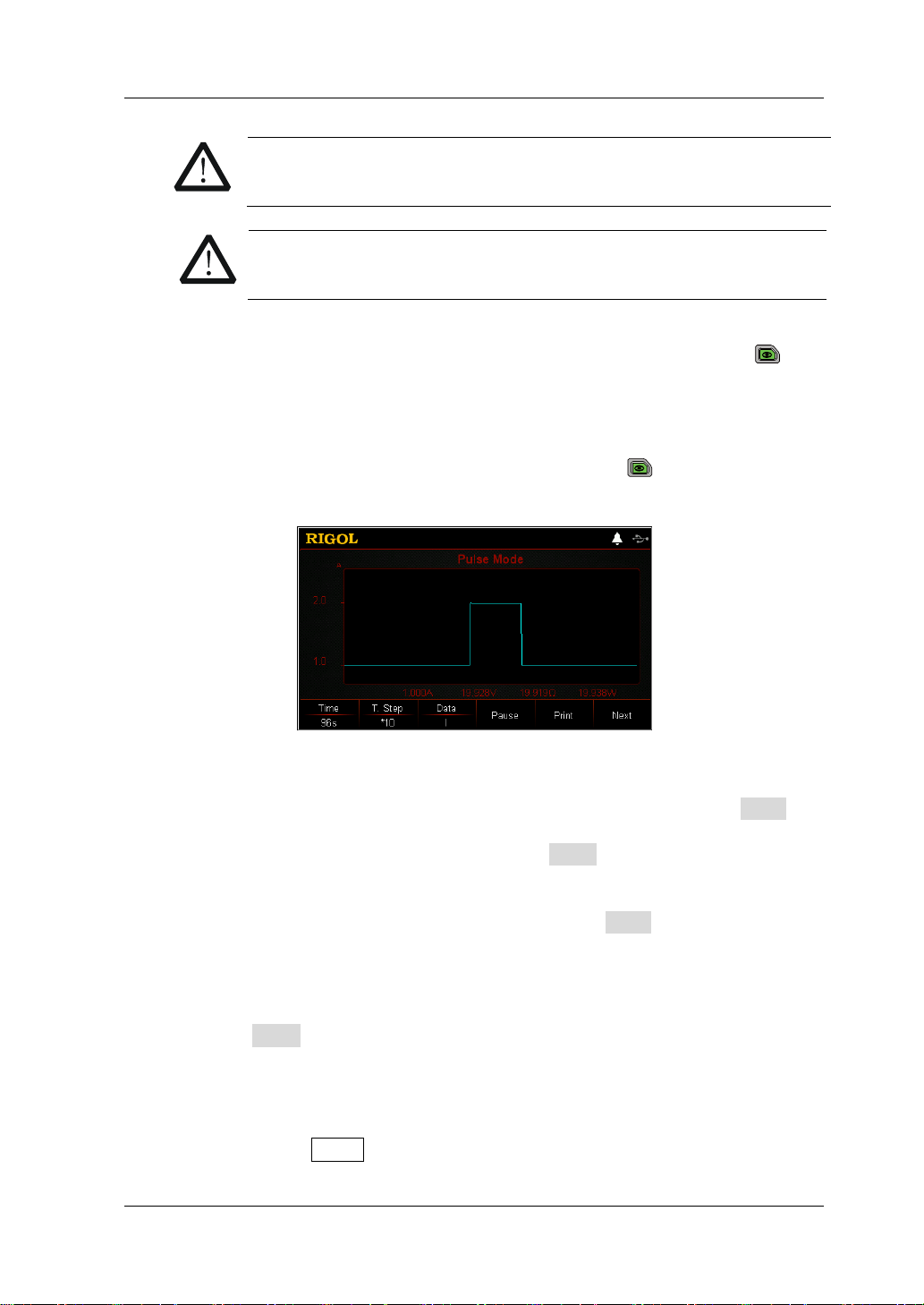
Chapter 2 Front Panel Operations RIGOL
CAUTION
WARNING
To avoid electric shock, ensure that the DUT is connected to the
input terminals of the load properly before you enable the trigger.
When the fan stops working, the channel is disabled. Then, a
message is displayed, "Fan stops running!"
6. View waveform display
After you enter the main interface, press the waveform display key
to
enter the waveform display interface, as shown in Figure 2-21. After t he load
current stays at Level A for a specified time (reach the set width), the trigger is
disabled automatically. Then, the current automatically switches to Level B. For
detailed operations, refer to the descriptions in "Waveform Display
Function" section. Press the waveform display key
again to exit the
waveform display interface and return to the main interface of Pul mode.
Figure 2-21 Waveform Display Interface of Pul Mode
7. Save and read files
In the guide interface and main interface of Pul mode, you can press Save to
save the parameters for Pul mode to the internal or external memory, and you
can read and recall it if necessary by pressing Read.
(1) Save
After you complete the parameter setting, press Save to enter the storage
and recall interface. The file is saved in ".PUL" format. For detailed saving
operation, refer to the descriptions in "
Save".
(2) Read
Press Read to enter the storage and recall interface. Recall and read the
files in ".PUL" format or the ".RS F" files beginning with " PUL_". F or detailed
reading operation, refer to descriptions in "
Read". The files to be recalled
and read are allowed to be edited.
How to press the Store key on the front to perform the saving and reading
DL3000 User’s Guide 2-29
Page 60

RIGOL Chapter 2 Front Panel Operations
operation, refer to the descriptions in "Store and Recall".
8. Exit Pul mode
Press any key on the front panel of the load to exit Pul mode.
2-30 DL3000 User’s Guide
Page 61

Chapter 2 Front Panel Operations RIGOL
CAUTION
TRIG
A
B
CC Toggled Mode (Tog)
In Tog mo de, when y ou e nable the t ransient te st, th e load cur rent will t oggle f or one
time between Level A and Level B once the load re ceives a trigger si gnal, as shown in
Figure 2-22.
TRIG
Figure 2-22 CC Toggled Mode (Tog)
Operation Procedures:
1. Connect the DUT and the channel input terminals of the load
Turn off the instrument, as shown in Figure 2-2, connect the DUT and the
channel input terminals on the front panel of the load.
While making a connection, the positiv e pola rit y of the load should
be connected to the (+) terminal of the channel output, and the
negative polarity of the load to the (-) terminal of the channel
output. A misconnection with the terminals may cause damage to
the instrument or the DUT.
2. Power on the instrument
After the instrument is connected to the power source, press the Power key
on the front panel to power on the instrument.
3. Set channel parameters in the guide interface
Press Tog to enter the Tog guide interface, as shown in Figure 2-23
guide interface, you can configure parameters in the parameter configuration
list and view the configuration diagram at the left of t he configuration list in the
real-time manner.
. In the
DL3000 User’s Guide 2-31
Page 62

RIGOL Chapter 2 Front Panel Operations
CAUTION
Figure 2-23 Guide Interface of T o g Operation
The parame te rs f or the to ggled operat io n m ode incl ude ra n ge, Lev el A, Level B,
rising slew rate, falling slew rate, and trigger source.
Set Range
The current working range in Tog mode. Two current ranges are av ai lable:
DL3021/DL3021A: low range (0 to 4 A); high range (0 to 40 A)
DL3031/DL3031A: low range (0 to 6 A); high range (0 to 60 A)
(1) In the guide interface, press the Up/Down arrow key to switch the
parameter focus to " Range".
(2) Use the Left/Right arrow key or the knob to switch the current working
range.
Note:
The low range provides better resolution and accuracy at low current
settings.
If the set current value is greater than t he maximum v alue of the low range,
you must select a high range.
2-32 DL3000 User’s Guide
Before switching the current range, please disa ble th e channel input
to avoid causing damage to the instrument or the DUT.
Set A_Level
The sink current toggles between a high value and a low value in Tog mode.
A_Level indicates a high value. The default unit fo r A_Level is Ampere (A).
(1) In the guide interface, press the Up/Down arrow key to switch the
parameter focus to " A_Level".
(2) Enter a value by using the numeric keys. For the setting methods, refer to
the descriptions in "Par a m e te r Setting Me th o d ".
Note: The input value of A_Level should be within the set range.
Page 63

Chapter 2 Front Panel Operations RIGOL
Set B_Level
The sink current toggles between a high value and a low value in Tog mode.
B_Level indicates a low value. The default unit for B_Level is Ampere (A).
(1) In the guide interface, press the Up/Down arrow key to switch the
parameter focus to "B_Level".
(2) Enter a value by using the numeric keys. For the setting methods, refer to
the descriptions in "Par a m e te r Setting Me th o d ".
Note: The set A_Level and B_Level for a specified model should be within its
specified high and low ranges for the model.
Set Slew_RIS
Sets the sink current sle w rate for t he positive t ransitions from Level B to Level A
in Tog mode. The default unit for the rising slew rate is A/μs.
(1) In the guide interface, press the Up/Down arrow key to switch the
parameter focus to " Slew_RIS".
(2) Enter a value by using the numeric keys. For the setting methods, refer to
the descriptions in "Para me te r Setting Me th o d ".
Set Slew_FAL
Sets the sink current s lew rate for t he negative tr ansitions from LevelA to Leve lB
in Tog mode. The default unit for the falling slew rate is A/μs.
(1) In the guide interface, press the Up/Down arrow key to switch the
parameter focus to " Slew_FAL".
(2) Enter a value by using the numeric keys. For the setting methods, refer to
the descriptions in "Par a m e te r Setting Me th o d ".
Set TRIG_SRC
Three triggers are available in Pul mode: BUS trigger, TRAN trigger, and DIGIO
trigger.
(1) In the guide interface, press the Up/Down arrow key to switch the
parameter focus to " TRIG_SRC".
(2) Press the Left/Right arrow key to select the type of the trigger source.
4. Enter the ma in interface
In the guide interface, after y ou configure the parameters, press Apply to enter
the main interface, as shown in
Figure 2-24. At this time, the parameters are
successfully configured. "CC" and "Toggle" are active at the top of the main
interface. Of which, "Toggle" is highlighted. In the guide interface , if you giv e up
configuring parameters , you can press Cancel to exit the guide interface and
enter the main interface.
DL3000 User’s Guide 2-33
Page 64
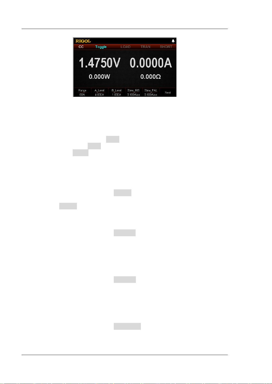
RIGOL Chapter 2 Front Panel Operations
Figure 2-24 Main Interface o f Tog Operation
The menus of the main interfac e ar e displayed in two pages .
Menu ite ms on Page 1: Range, A_Level, B_Level, Slew_RIS, Slew_FAL, and
Next.
Menu ite ms on Page 2: TRIG_SRC, Gu i de, Read, Save, and Back.
To go to t he next page, p r es s Next; to exit the current page and go back to the
previous page, press Back; to go back to the guide interface from the main
interface, press Guide.
In the main interface, you can also set parameters based on your own needs.
The setting methods for the parameters are as follows:
Set Range
(1) In the main interface, press Range to switch the parameter focus to
"Range".
(2) Press Range to switch the current working range. You can also use the
Left/Rig h t arrow key or the knob to switch it.
Set A_Level
(1) In the main interface, press A_Level to switch the parameter focus to
"A_Level".
(2) Enter a value by using the numeric keys, arrow keys, or the knob. For the
setting methods, refer t o t he des criptions of the b uilt -in hel p inf ormatio n or
refer to the descriptions in "Param eter Settin g Method".
Set B_Level
(1) In the main interface, press B_Level to switch the parameter focus to
"B_Level".
(2) Enter a value by using the numeric keys, arrow keys, or the knob. For th e
setting methods, refer t o t he des criptions of the b uilt -in hel p inf ormatio n or
refer to the descriptions in "Parameter Setting Method".
Set Slew_RIS
(1) In the main interface, press Slew_RIS to switch the parameter focus to
"Slew_RIS".
(2) Enter a value by using the numeric keys , arrow keys , or the kn ob. F or setting
2-34 DL3000 User’s Guide
Page 65

Chapter 2 Front Panel Operations RIGOL
WARNING
message is displayed, "Fan stops running!"
Tip
methods, refer to the descriptions of the help information or refer to the
descriptions in "Parameter Setting Method".
Set Slew_FAL
(1) In the main interface, press Slew_FAL to switch the parameter focus to
"Slew_FAL".
(2) Enter a value by using the numeric keys, arrow keys, or the knob. For
setting methods, refer to the descriptions of the help informat ion or refer to
the descriptions in "Par a m e te r Setting Me th o d ".
Set TRIG_SRC
(1) In the main interface, press TRIG_SRC to switch the parameter focus to
"TRIG_SRC".
(2) Press TRIG_SRC to select the t y pe of the trigger source. You can also use
the Left/Right arrow key or the knob to s e l e ct it.
In the guide interface, you can only use the numeric keys to input the value
for the parameter; in the main interface, you can use the numeric keys, the
arrow keys, or the knob to input the value for the parameter.
5. Enable trigger
After you enable the trigger, the actual input voltage, current, resistance, and
power of the load will be displayed in the main interface.
Tip
You can enable the trigger first and then the load inp ut is automatic ally turned
on (The load sinks the current of Level B, and then the input will be updated
according to the preset value). You can also press the ON/OFF key on the
front panel first to turn on the input before you enable the trigger (The load
sinks the current of Level B, and then waits trigger to occur. After the trigger is
enabled, the input will be updated according to the preset value).
To avoid electric shock, ensure that the DUT is connected to the
input terminals of the load properly before you enable the trigger.
CAUTION
When the fan stops working, the channel is disabled. Then, a
DL3000 User’s Guide 2-35
Page 66
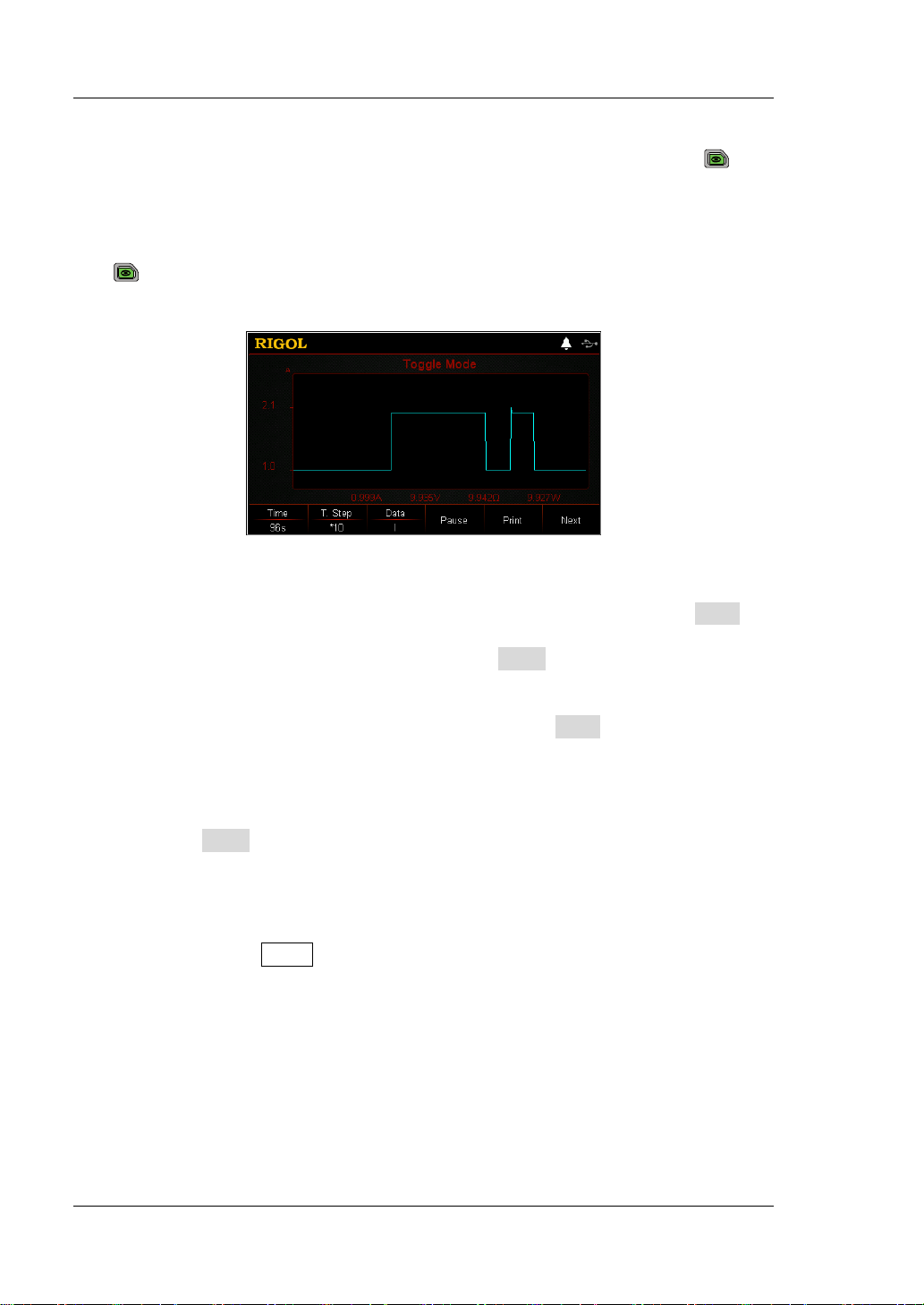
RIGOL Chapter 2 Front Panel Operations
6. View waveform display
After you enter the main interface, press the waveform display key
to
enter the waveform display interf ace , as sh own in Figure 2-25. The load current
will always sta y at Level A and it will not swit ch to Le vel B unless you disable the
trigger manually. For detailed operations, refer to the descriptions in
"Waveform Display Function" section. Press th e wavef orm display key
again to exit the wav eform display inte rface and return to the main interfac e
of Tog mode.
Figure 2-25 Wave fo rm Display Interface of Tog Mode
7. Save and read files
In the guide interface and main interface of Tog mode, you can press Save to
save the parameters for Tog mode to the internal or external memory, and you
can read and recall it if necessary by pressing Read.
(1) Save
After you complete the parameter setting, press Save to enter the storage
and recall interface. The file is saved in ".TOG" format. For detailed saving
operation, refer to the descriptions in "
Save".
(2) Read
Press Read to enter the storage and recall interface. Recall and read the
files in ".TOG" format or the ".RSF" f iles beginning with "TOG_". For
detailed reading operation, refer to descriptions in "
Read". The files to be
recalled and read are allowed to be edited.
How to press the Store key on the front to perform the saving and reading
operation, refer to the descriptions in "Store and Recall".
8. Exit Tog mode
Press any key on the front panel of the load to exit Tog mode.
2-36 DL3000 User’s Guide
Page 67
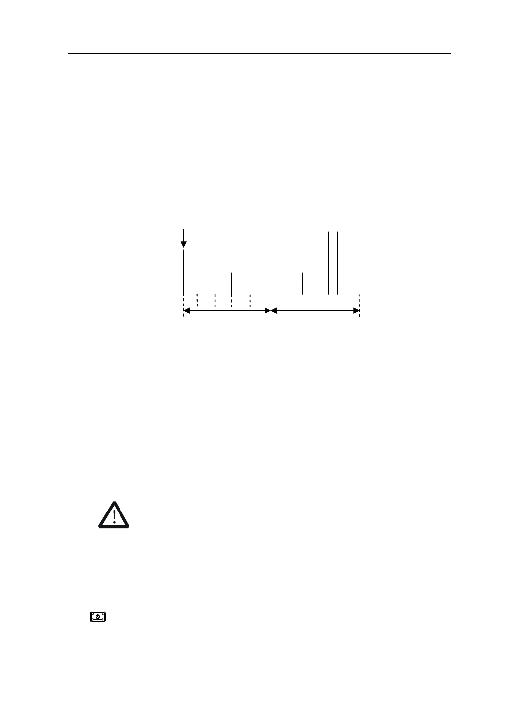
Chapter 2 Front Panel Operations RIGOL
CAUTION
TRIG
Circle=1
TRIG
Circle=1
4
5
TRIG
Circle=1
List Operation Function (List)
In list operation mode, you can perform the complex
current/voltage/resistance/power modes accurately and rapidly, which may be
synchronized with internal or external signals. In this way, you can complete the
sophisticated test.
In this mode, when receiving a trigger signal, the load will operate according to the
set execution mode and sequence. As shown in Figure 2-26, the load simulates the
complex sequences of in put chan ges base d on the li st pa ra meters that y ou e dit . The
list function supports CC, CV, CR, and CP modes.
When selecting different trigger sources, you can generate complex sequences by
editing the setting value for each step, the dwell time, and slew rate (the slew rate
can only be edited in CC mode) to meet the complex test demands. All listed data is
stored in a n on-v olatile memory. It means that the data will not be lost when th e load
is turned off.
Operation Procedures:
1. Connect the DUT and the channel input terminals of the load
Turn off the instrument, as shown in Figure 2-2, connect the DUT and the
channel input terminals on the front panel of the load.
0
0
0
2 3
1
Circle=2
Circle=2
Circle=2
Figure 2-26 List Operation Function (List)
While making a connection, the positive polarity of the load should
be connected to the (+) terminal of the channel output, and the
negative polarity of the load to the (-) terminal of the channel
output. A misconnection with the terminals may cause damage to
the instrument and the devices connected to it.
2. Power on the instrument
After the instrument is connected to the power source, press the Power key
on the front panel to power on the instrument.
DL3000 User’s Guide 2-37
Page 68
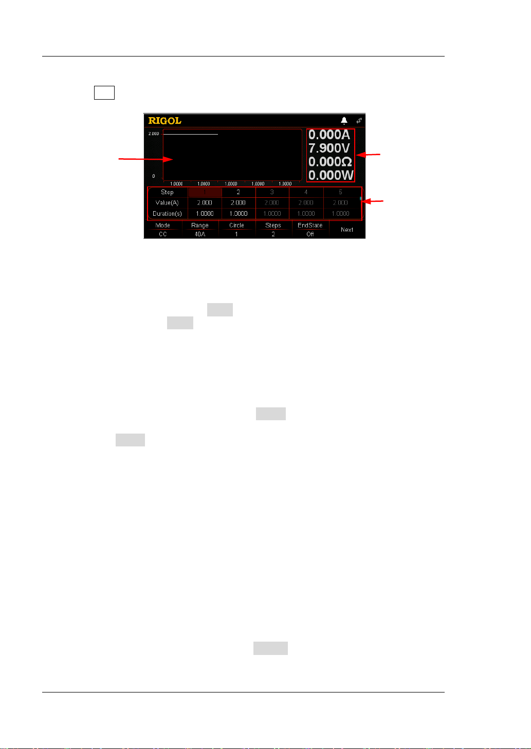
RIGOL Chapter 2 Front Panel Operations
Parameter
Parameter
Diagram
3. Set channel parameters
Press List to enter the list function interface, as shown in Figure 2-27
.
Preview
Actual Input
Values
List
Figure 2-27 List Function Interface
The menus of the list function interface are displayed in two pages.
Menu items on Page 1: Mode, Range, Cycles, Steps, EndState, and Next.
Menu ite ms on Page 2: TRIG_SRC, Save, Read, Recor d, and Back .
To go to t he next page, press Next; to exit the current page and go back to the
previous page, press Back.
The setting methods for the parameters are as follows:
Set Mode
Sets the working modes that the List function supports. The modes include CC,
CV, CR, and CP.
(1) In the List function interfa ce, p ress Mode to switch the parameter focus to
"Mode".
(2) Press Mode to switch the working mode. You can also use the Left/Right
arrow key or the knob to swi t ch it.
Set Range
Selects a different range based on the current working mode of List. There is no
range available in CP mod e .
If "C C" is selected to be the working mode, the r ange selection is as follows:
DL3021/DL3021A: low range (0 A to 4 A); high range (0 A to 40 A)
DL3031/DL3031A: low range (0 A to 6 A); high range (0 A to 60 A)
If "CV" is selected to be the working mo de, the ran ge selection is as follows:
low range (0 V to 15 V); high range (0 V to 150 V)
If "CR" is s elected to be th e working mode , the rang e selection is as follows:
low range (0.08 Ω to 15 Ω); high range (2 Ω to 15 kΩ)
(1) In the List function interfa ce, press Range to switch the parameter focus to
"Range".
2-38 DL3000 User’s Guide
Page 69
Chapter 2 Front Panel Operations RIGOL
CAUTION
Tip
(2) Press Range to switch the workin g ran ge for dif ferent modes. You can als o
use the Left/Right arrow key or the knob to switch it.
Note:
The low range provides better resolution and accuracy at low settings.
If the set value is greater than the maximum value of the low range, you
must select a high range.
Before switching the range, please disable the channel input to
avoid causing damage to the instrument or the DUT.
Set Circle
Sets the number of times t he list is cycled whe n t iming in put is completed based
on the preset current/voltage/resistance/power. Its range is from 0 to 99999.
When the value is 0, the value under "Circle" is displayed to be "Infinite", and
then the load will be switched to infinite mode.
(1) In the List function interface, press Circle to switch the para meter focus to
"Circle".
(2) Enter a value by using the numeric keys, arrow keys, or the knob. For
setting methods, refer to the descriptions of the help infor mation or refe r to
the descriptions in "Par a m e te r Setting Me th o d ".
Set Steps
Sets the number of steps for the input preset current/voltage/resistance/power
in each cycle. Its range is from 2 to 512.
(1) In the List function interface, press Steps to switch the parameter focus to
"Steps".
(2) Enter a value by using the numeric keys, arrow keys, or the knob. For the
setting methods, refer to the descriptions of the built-in help information or
refer to the descriptions in "Parameter Setting Method".
Total Steps = Steps x Circle
You can edit up to 512 groups of data.
Set EndState
Last state: when the number of execution times (Circle) is a finite value, last
state refers to the state the load stays after the load completes the total steps of
current/voltage/resistance/power inputs.
Off: indicates that the input will be turned off automatically after the input is
completed.
Last: k eeps the input state of the last group after the input is completed.
(1) In the List function interface, press EndState to switch the parameter
focus to " EndState".
DL3000 User’s Guide 2-39
Page 70

RIGOL Chapter 2 Front Panel Operations
disabled and grayed out.
(2) Press EndState to switch the last working state. You can also use the
Left/Right arrow key or the knob to switch it.
Tip
When the number of execut ion times (Circle) is set to "Infinite", "EndState" is
Set TRIG_SRC
Three triggers are available in List mode: BUS trigger, TRAN trigger, and DIGIO
trigger.
(1) In the main interface, press TRIG_SRC to switc h the parameter focus to
"TRIG_SRC".
(2) Press TRIG_SRC to select the t y pe of the trigger source. You can also use
the Left/Right arrow key or the knob to select it.
Set Parameter List
The parameter list consists of the following parameters: Step, Value, Duration,
Slew (only available in CC mode), V_Sampling (V)/C_Sampling (A). Step
indicates the number of steps; Value indicates the value set for each step;
Duration indicates the dwell time for each step; Slew indicates the slew rate for
each step; V_Sampling (V) indicates the readback sampling voltage; and
C_Sampling (A) indicates the readback sampling current. If the scrollbar is
shown at the right side of the para meter list, it indicates that not all paramet ers
are displayed in the cur rent interface. At this time, press the Up/Down arrow key
to go to the next page.
(1) Select Step
The Step value in the par ameter list is related to the setting of "Steps" in the
menu. For example, press Steps to set it to 4, then the first 4 steps in the
parameter list and the relevant parameters are highlighted.
If the number of steps that you set is a small value, you only need to use
the Left/Right arrow key or the knob to directly select the desired number of
steps.
If the number of steps that you set is a large value, you can input the
desired steps by using the numeric keys first. After that, you will dire ctly go
to the column under the desired steps. For example, if you set Steps to 300,
and you want to set the parameters for Step 250, then use the numeric
keys to input 250 and you will go t o St ep 250 directly. At thi s time, you can
set the relevant parameters.
If the parameter focus is currently not on the "Step" line, first press the
Up/Down arrow key to switch the parameter focus to the "Step" line, and
then select the desired steps.
2-40 DL3000 User’s Guide
Page 71

Chapter 2 Front Panel Operations RIGOL
(2) Enter Value
In CC mode, the set value is for current, and its default unit is A.
In CV mode, the set value is for voltage, and its default unit is V.
In CR mode, the set value is for resistance, and its default unit is Ω.
In CP mode, the set value is for power, and its default unit is W.
a) In the main interface, press the Up/Down arrow key to switch the
parameter focus to the "Value" line.
b) Enter a value by using the numeric keys. For setting methods, refer to
the descriptions in "Par a m e te r Setting Me th o d ".
Note: If the parameter focus is on the "Value" line, press the Left/Right
arrow key or rotate the knob to set the value for the adjacent step.
(3) Set Duration
The default unit for duration is s. Its range is 0.00005 s to 3600 s.
Press the Up/Down arrow key to switch the parameter focus to the
"Duration" line.
Enter a value by using the numeric keys. For setting methods, refer to
the descriptions in "Parameter Setting Method".
Note: When the current parameter focus is on the "Duration" line, press
the Left/Right arrow key or rotate the knob to switch the parameter focus to
the duration for the adjacent step.
(4) Set Slew (only available in CC mode)
The default unit for the slew rate is A/μs.
In the main interface, press the Up/Down arrow key to switch the
parameter focus to the "Slew" line.
Enter a value by using the numeric keys. For setting methods, refer to
the descriptions in "Par a m e te r Setting Me th o d ".
Note: If the parameter focus is on the "Slew" line, press the Left/Right
arrow key or rotate the knob to set the value for each step.
(5) Set V_Sampling (V)/C_Sampling (A)
After the list operation is finished, the readback value for each step in the
last cycle (that is, the last sampling value stably displayed for each step in
the last cycle) will be automatically displayed in the parameter list. In CC
mode, readback voltage (V_Sampling (V)) is displa yed; in CV mode,
readback current (C_Sampling (A)) is displayed; and in CR and CP modes,
both readba ck volta ge (V_Sam pling (V )) and rea dback cur rent (C_S amplin g
(A)) are displayed.
4. Enable trigger
After you complete the parameter setting, turn on the trigger, and then the load
DL3000 User’s Guide 2-41
Page 72
RIGOL Chapter 2 Front Panel Operations
Tip
Before enabling the trigger, ensure that the changes of the input will not
input terminals of the load properly before you enable the trigger.
CAUTION
will input base d on the c urrent set tings. If the trigger i s tu rned off during the lis t
operation, the next t ime you turn on the t ri gger, the load will continue inputting
the last parameter where you stop the list operation.
The actual input voltage, current, resistance, and power of the load will be
displayed in the main interface in a real-time manner. In the parameter
preview area, you can view the dynami c changes of the parameters in the
parameter list.
In the parameter list, the editing box is highlighted in green.
If the number of execution times ("Cycles") is set to be a specif ied value,
after completing the number of inputs (total steps), the load will terminate
inputting. At this time, the end state of the load is determined by
"EndState". When th e number of execution times ("Cycles") is set to
"Infinite", the load makes consecutive inputs based on the current
parameter settings. At this time, the end state is invalid.
After the trigger is enabled, the load input is automatically enabled (The
load first inputs the data for the first step and then inputs according to
the preset values). Y o u can also press the ON/OFF key on the front
panel first to turn on the input before you enable the trigger (The load
fi r s t inpu ts th e data for the first step and then wait for trigge r to occ u r.
After the trigger is enabled, the load inputs according to the preset
values).
affect the DUT.
Please complete the pa rameter set ting bef ore enabling t he trigge r. During
the list operation, you are not allowed to modify the parameters.
WARNING
To avoid electric shock, ensure that the DUT is connected to the
When the fan stops working, the channel is disabled. Then, a
message is displayed, "Fan stops running!"
5. Save and read files
In the List function inter face, you ca n press Save to save the parameters for List
mode to the internal or external memory, and you can read and recall it if
necessary by pressing Read.
(1) Save
After you complete the parameter setting, press Save to enter the storage
2-42 DL3000 User’s Guide
Page 73

Chapter 2 Front Panel Operations RIGOL
Tip
and recall interface. The file is saved in ".LST" format. For detailed saving
operation, refer to the descriptions in "Save".
(2) Read
Press Read to enter the storage and recall interface. Recall and read the
files in ".LST" format or the ".RSF" files beginning with "LST_". For detailed
reading operation, refer to descriptions in "
Read". The files to be recalled
and read are allowed to be edited.
How to press the Store key on t he front pa nel of the load t o pe rfo rm the sa vi ng
and reading operation, refer to the descriptions in "Store and Recall".
6. Record data file
In the List function interface, you can press Record to record the data file and
save it to the external memory in CSV format. During recording, "Record" is
displayed at the t op of the interface. Press Record again to stop recording, and
then "Record" is not displayed at the top of the interface.
Connect the external memory U Disk to t he PC , and r ead the data files in CSV
format from the U Disk.
7. Exit List mode
Press any key on the front panel of the load to exit List mode.
DL3000 User’s Guide 2-43
Page 74

RIGOL Chapter 2 Front Panel Operations
t
V
t
V
V
Application Function
The load supports the following three application functions. Press APP to switch
among the three functions.
OCP test function
OPP test function
Battery test function
OCP Test Function
OCP test principle (as shown in Figure 2-28)
When the OCP test s ta rts, after the input v oltage reaches Von, the load will del a y f or
a period, then starts to sink the current, increasing with incrementing steps at a
certain interval. Meanwhile, the load will compare the detected voltage value with
the OCP protection voltage value. If higher than the protection voltage value, the
load proceeds to run and increases with incrementing steps until reaching the
protection voltage.
If OCP occurs to the DUT, judge whether the current under test is within the
maximum and minimum current range. If yes, the load passes the OCP test; if no,
the load fails the test.
If no OCP occurs to the DUT and the set protection time times out, the load
automatically stops sinking. The OCP test fails, and the test ends.
I
I
I
Starting Current
Step Delay
Figure 2-28 OCP Test Function
Operation Procedures:
1. Connect the DUT and the channel input terminals of the load
Turn off the instrument, as shown in Figure 2-2, connect the DUT and the
channel input terminals on the front panel of the load.
Output Voltage of DUT
Load Current
Step Current
End Current
t
2-44 DL3000 User’s Guide
Page 75

Chapter 2 Front Panel Operations RIGOL
CAUTION
While making a connection, the positive polarity of the load should
be connected to the (+) terminal of the channel output, and the
negative polarity of the load to the (-) terminal of the channel
output. A misconnection with the terminals may cause damage to
the instrument or the DUT.
2. Power on the instrument
After the instrument is connected to the power source, press the Power key
on the front panel to power on the instrument.
3. Set channel parameters in the guide interface
Press APP to switch to the g uide inter face of the O CP test function, as shown in
Figure 2-29. In the guide interface, you can configure parameters in the
parameter configuration list and view the configuration diagr am at the left of th e
conf iguration list in the real-time manner. If the scrollbar appears at the right
side of the parameter list, it indicates that n ot all para meters are display ed in the
current interface. At this time, press the Up/Down arrow key to go to the next
page.
Figure 2-29 Guide Interface of OCP Test Function
The parameters for the OCP test function include range, starting voltage, delay
time, starting current, step current, step delay, protection voltage, maximum
current, minimum current, and protection time.
Set Range
The current working range for the OCP test function. Two current ranges are
available:
DL3021/DL3021A: low range (0 to 4 A); high range (0 to 40 A)
DL3031/DL3031A: low range (0 to 6 A); high range (0 to 60 A)
(1) In the guide interface, press the Up/Down arrow key to switch the
parameter focus to " Range".
(2) Use the Left/Right arrow key or the knob to switch the current working
range.
DL3000 User’s Guide 2-45
Page 76

RIGOL Chapter 2 Front Panel Operations
Note:
The low range provides better resolution and accuracy at low current
settings.
If the set current v alue is g reater than the maximum v alue of the low range,
you must select a high range.
Set Von
When the input voltage is greater than the set starting voltage (Von), the load
starts to sink the cu rrent. T he def ault unit for Von is V, and it ranges from 0 V to
150 V. The default Von is 0.01 V.
(1) In the guide interface, press the Up/Down arrow key to switch the
parameter focus to " Von".
(2) Enter a value by using the numeric keys. For setting methods, refer to the
descriptions in "Parameter Setting Method".
Set Delay_Von
Sets the time period for how long the load starts to sink the current after the
input voltage reaches Von. The default unit for the delay time is ms.
(1) In the guide interface, press the Up/Down arrow key to switch the
parameter focus t o "Delay_Von".
(2) Enter a value by using the numeric keys. For setting methods, refer to the
descriptions in "Parameter Setting Method".
Set C_Start
The current value when the load starts in OCP test mode. The default unit for
the value is A.
(1) In the guide interface, press the Up/Down arrow key to switch the
parameter focus to " C_Start".
(2) Enter a value by using the numeric keys. For setting methods, refer to the
descriptions in "Parameter Setting Method".
Set C_Step
The step current in OCP test mode. The default unit for the value is A.
(1) In the guide interface, press the Up/Down arrow key to switch the
parameter focus to " C_Step".
(2) Enter a value by using the numeric keys. For setting methods, refer to the
descriptions in "Parameter Setting Method".
Set Delay_Step
The time interval during which the current moves from step to step in OCP test
mode. The default unit for the value is ms.
(1) In the guide interface, press the Up/Down arrow key to switch the
parameter focus to " Delay_Step".
(2) Enter a value by using the numeric keys. For setting methods, refer to the
descriptions in "Parameter Setting Method".
2-46 DL3000 User’s Guide
Page 77

Chapter 2 Front Panel Operations RIGOL
Set OCP_V
The protection voltage in the OCP t est mode. The default unit for the v alue is V.
(1) In the guide interface, press the Up/Down arrow key to switch the
parameter focus to " OCP_V".
(2) Enter a value by using the numeric keys. For setting methods, refer to the
descriptions in "Parameter Setting Method".
Set C_Max
The maximum value of th e protection current in the OC P test mode. The defa ult
unit for the value is A.
(1) In the guide interface, press the Up/Down arrow key to switch the
parameter focus to " C_Max".
(2) Enter a value by using the numeric keys. For setting methods, refer to the
descriptions in "Parameter Setting Method".
Set C_Min
The minimum value of the protection current in the OCP test mode. The defaul t
unit for the value is A.
(1) In the guide interface, press the Up/Down arrow key to switch the
parameter focus to " C_Min".
(2) Enter a value by using the numeric keys. For setting methods, refer to the
descriptions in "Parameter Setting Method".
Set T_Limit
The maximum overcurrent protection time in OCP mode. If no action is
performed during the protection time, the load will automatically stop sinking
the current. The default unit for the value is
μs.
(1) In the guide interface, press the Up/Down arrow key to switch the
parameter focus to " T_Limit".
(2) Enter a value by using the numeric keys. For setting methods, refer to the
descriptions in "Parameter Setting Method".
4. Enter the ma in interface
In the guide interface, after you configure the parameters, press Apply to enter
the main interface, as shown in
Figure 2-30. At this time, "OCP" is active at the
top of the main interface, which indicates that the parameters have been
successfully configured. In the guide interface, if you give up configuring
parameters, you can press Cancel to exit the guide i nterface and ent er the main
interface.
DL3000 User’s Guide 2-47
Page 78

RIGOL Chapter 2 Front Panel Operations
Figure 2-30 Main Interface of OCP Test Function
The menus of the main interfac e ar e displayed in three pages.
Menu items on Page 1: Range, Von, Delay_Von, C_Start, C_Step, and Next .
Menu items on Page 2: Delay_Step, OCP_V, C_Max, C_Min, Back, and Next.
Menu ite ms on Page 3: T_Limit, Guide, Read, Save, and Back.
To go to t he next page, p r es s Next; to exit the current page and go back to the
previous page, press Back; to go back to the guide interface from the main
interface, press Guide.
In the main interface, you can also set parameters based on your own needs.
The setting methods for the parameters are as follows:
Set Range
(1) In the main interface, press Range to switch the parameter focus to
"Range".
(2) Press Range to switch the current working range. You can also use the
Left/Right arrow key or the knob to switch it.
Set Von
(1) In the main interface, press Von to switch the parameter focus to "Von".
(2) Enter a value by using the numeric keys, arrow keys, or the knob. For the
setting methods, refer to the descriptions of the built -in help informatio n or
refer to the descriptions in "Parameter Setting Method".
Set Delay_Von
(1) In the main interface, press Delay_Von to switch the parameter focus to
"Delay_Von".
(2) Enter a value by using the numeric keys, arrow keys, or the knob. For
setting methods, refer to the descriptions of the help informat ion or refer to
the descriptions in "Par a m e te r Setting Me th o d ".
Set C_Start
(1) In the main interface, press C_Start to sw itch the parameter focus to
"C_Start".
(2) Enter a value by using the numeric keys, arrow keys, or the knob. For
setting methods, refer to the descriptions of the help informat ion or refer to
2-48 DL3000 User’s Guide
Page 79

Chapter 2 Front Panel Operations RIGOL
the descriptions in "Par a m e te r Setting Me th o d ".
Set C_Step
(1) In the main interface, press C_Step to switch the parameter focus to
"C_Step".
(2) Enter a value by using the numeric keys, arrow keys, or the knob. For the
setting methods, refer to the descripti ons of the built -in help informatio n or
refer to the descriptions in "Parame te r Se t ting Method ".
Set Delay_Step
(1) In the main interface, press Delay_Step to switch the parameter focus to
"Delay_Step".
(2) Enter a value by using the numeric keys, arrow keys, or the knob. For the
setting methods, refer t o t he des criptions of the b uilt -in hel p inf ormatio n or
refer to the descriptions in "Parameter Setting Method".
Set OCP_V
(1) In the main interface, press OCP_V to switch the parameter focus to
"OCP_V".
(2) Enter a value by using the numeric keys, arrow keys, or the knob. For the
setting methods, refer t o t he des criptions of the b uilt -in hel p inf ormatio n or
refer to the descriptions in "Parameter Setting Method".
Set C_Max
(1) In the main interface, press C_Max to switch the parameter focus to
"C_Max".
(2) Enter a value by using the numeric keys, arrow keys, or the knob. For the
setting methods, refer to t he des criptions of the built-in help information or
refer to the descriptions in "Parameter Setting Method".
Set C_Min
(1) In the main interface, press C_Min to switch th e parameter focus to
"C_Min".
(2) Enter a value by using the numeric keys, arrow keys, or the knob. For
setting methods, refer to the descriptions of the help informat ion or refer to
the descriptions in "Par a m e te r Setting Me th o d ".
Set T_Limit
(1) In the main interface, press T_Limit to switch the parameter focus to
"T_Limit".
(2) Enter a value by using the numeric keys, arrow keys, or the knob. For
setting methods, refer to the descriptions of the help informat ion or refer to
the descriptions in "Par a m e te r Setting Me th o d ".
DL3000 User’s Guide 2-49
Page 80

RIGOL Chapter 2 Front Panel Operations
WARNING
CAUTION
Tip
In the guide interface, yo u can only use the numeri c keys to input the v alue for the
parameter; in the main interface, y ou can use the numeric keys, the arrow keys , or
the knob to input the value for the parameter.
5. Turn on the channel input
Press On/Off to turn on the channel input. At this time, the actual input
voltage, current, resistance, and power will be displayed in the main interface.
If the load passes the test, a prompt message is displayed, "OCP test passed!"
The DUT will automatically turn off output.
If the load fails the test, one of the following prompt messages is displayed:
"Upper limit exceeded. OCP test failed!" "Lower limit exceeded. OCP test failed!"
Or "Timeout! OCP test failed!" Then, the channel input of the load will be
automatically turned off.
To avoid electric shock, ensure that the DUT is connected to the
input terminals of the load properly before you turn on the channel
input.
When the fan stops working, the channel is disabled. Then, a
message is displayed, "Fan stops running!"
6. View waveform display
After you enter the main interface, press the waveform display key
enter the waveform display interface, as shown in Figure 2-31. The current will
have a stepped increase. If the OCP test is successful, the current will increase
until it reaches the protection current of the DUT; if the OCP test fails, the
current will increase until it reaches the set maximum current. For detailed
operations, refer to the de scriptions in "Wav eform Dis play Func tion" section.
Press the waveform display key
again to exit the waveform display
interface and return to the main interface of OCP test function.
Figure 2-31 OCP Waveform Display Interface
to
2-50 DL3000 User’s Guide
Page 81

Chapter 2 Front Panel Operations RIGOL
7. Save and read files
In the guide interface an d main interface of OCP test mo de, you can press Save
to save the parameters for the OCP test mode to the internal or external memor y ,
and you can read and recall it if necessary by pressing Read.
(1) Save
After you complete the parameter setting, press Save to enter the storage
and recall interface. The file is saved in ".OCP" format. For detailed saving
operation, refer to the descriptions in "
Save".
(2) Read
Press Read to enter the storage and recall interface. Select the files that
are in ".OCP" format or the ".RSF" files beginning with "OCP_" to read and
recall. For detailed reading operation, refer to descriptions in "
Read". The
files to be recal led and read are allowed to b e e dited.
How to press the Store key on t he front pa nel of the load t o pe rfo rm the sa vi ng
and reading operation, refer to the descriptions in "Store and Recal l".
8. Exit the OCP test function
Press any key on the front panel of the load to exit the OCP test mode.
DL3000 User’s Guide 2-51
Page 82

RIGOL Chapter 2 Front Panel Operations
CAUTION
Output Voltage of DUT
Load Power
Starting Power
Step Power
Step Delay
End Power
t V
OPP Test Function
OPP test principle (as shown in Figure 2-32):
When the OPP test sta rts, after the in put v oltage rea ches Von, the load will dela y f or
a period, then the DUT starts to work according to the starting power. The power
increases with increasing with incrementing steps at a certain interval. Meanwhile,
the load will compare the detected v oltage v alue wit h the protection voltage v alue of
the OPP test. If higher than the protection voltage value, the load proceeds to run
and increases with incrementing steps until reaching the protection voltage.
If OPP occurs to the DUT, judge whether the power under test is within the set
maximum and minimum power range. If yes , the loa d passes the OP P test; if no, the
load fails the test.
If no OPP occurs to the DUT and the set protection time times out, the load
automatically stops sinking. The OPP test fails, and the test ends.
Operation Procedures:
1. Connect the DUT and the channel input terminals of the load
Turn off the instrument, as shown in Figure 2-2, connect the DUT and the
channel input terminals on the front panel of the load.
V
V
P
Figure 2-32 OPP Test Function
t
t
2-52 DL3000 User’s Guide
While making a connection, the positive polarity of the load should
be connected to the (+) terminal of the channel output, and the
negative polarity of the load to the (-) terminal of the channel
output. A misconnection with the terminals may cause damag e to
the instrument or the DUT.
Page 83
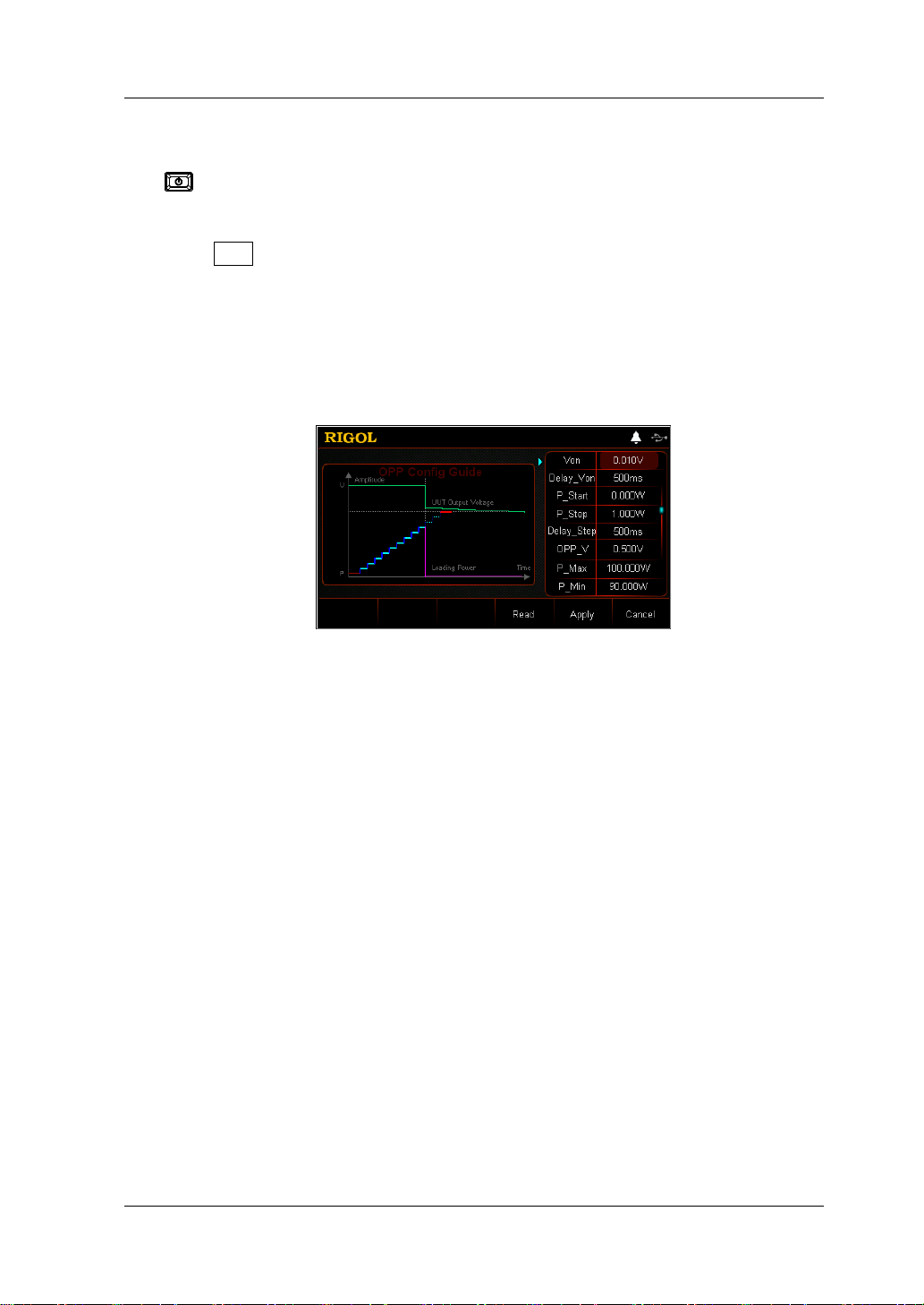
Chapter 2 Front Panel Operations RIGOL
2. Power on the instrument
After the instrument is connected to the power source, press the Power key
on the front panel to power on the instrument.
3. Set channel parameters in the guide interface
Press APP to switch t o the gui de interfa ce of the OPP test functio n, as sh own in
Figure 2-33. In the guide interface, you can configure parameters in the
parameter configuration list and view the configuration diagr am at the left of th e
configuration list in the real-time manner. If the scrollbar appears at the right
side of the parameter list, it indicates that n ot all para meters are display ed in the
current interface. At this time, press the Up/Down arrow key to go to the next
page.
Figure 2-33 Guide Interface of OPP Te st Functio n
The parameters for the OPP test function include starting voltage, delay time,
starting power, step power, step delay, protection voltage, maximum power,
minimum power, and protec t i o n time.
Set Von
When the input voltage is greater than the set starting voltage (Von), the load
starts to sink the cu rrent. T he def ault unit for Von is V, and it ranges from 0 V to
150 V. The default Von is 0.01 V.
(1) In the guide interface, press the Up/Down arrow key to switch the
parameter focus to " Von".
(2) Enter a value by using the numeric keys. For setting methods, refer to the
descriptions in "Parameter Setting Method".
Set Delay_Von
Sets the time period for how long the load starts to sink the current after the
input voltage reaches Von. The default unit for the delay time is ms.
(1) In the guide interface, press the Up/Down arrow key to switch the
parameter focus to " Delay_Von".
(2) Enter a value by using the numeric keys. For setting methods, refer to the
descriptions in "Parameter Setting Method".
DL3000 User’s Guide 2-53
Page 84

RIGOL Chapter 2 Front Panel Operations
Set P_Start
The power value when the load starts in O PP test mo de. The def ault unit for t he
value is W.
(1) In th e g uide interface, press the U p / Down arrow key to sw itch the
parameter focus to " P_Start".
(2) Enter a value by using the numeric keys. For setting methods, refer to the
descriptions in "Parameter Setting Method".
Set P_Step
The step power in OPP test mode. The default unit for the value is W.
(1) In the guide interface, press the Up/Down arrow key to switch the
parameter focus to " P_Step".
(2) Enter a value by using the numeric keys. For setting methods, refer to the
descriptions in "Parameter Setting Method".
Set Delay_Step
The time interval during which the power moves from step to step in OPP test
mode. The default unit for the value is ms.
(1) In the guide interface, press the Up/Down arrow key to switch th e
parameter focus to " Delay_Step".
(2) Enter a value by using the numeric keys. For setting methods, refer to the
descriptions in "Parameter Setting Method".
Set OPP_V
The protection voltage in the OPP test mode . The default unit f o r the value is V.
(1) In the guide interface, press the Up/Down arrow key to switch the
parameter focus to " OPP_V".
(2) Enter a value by using the numeric keys. For setting methods, refer to the
descriptions in "Parameter Setting Method".
Set P_Max
The maximum value of the protection power in the OPP test mode. The default
unit for the value is W.
(1) In the guide interface, press the Up/Down arrow key to switch the
parameter focus to " P_Max".
(2) Enter a value by using the numeric keys. For setting methods, refer to the
descriptions in "Parameter Setting Method".
Set P_Min
The minimum value of the protection power in the OPP test mode. The default
unit for the value is W.
(1) In the guide interface, press the Up/Down arrow key to switch the
parameter focus to " P_Min".
(2) Enter a value by using the numeric keys. For setting methods, refer to the
descriptions in "Parameter Setting Method".
2-54 DL3000 User’s Guide
Page 85

Chapter 2 Front Panel Operations RIGOL
Set T_Limit
The maximum overpower protection time in OPP mode. If no action is
performed during the protection time, the load will automatically stop sinking
the current. The default unit for the value is
μs.
(1) In the guide interface, press the Up/Down arrow key to switch the
parameter focus to " T_Limit".
(2) Enter a value by using the numeric keys. For setting methods, refer to the
descriptions in "Para meter Settin g Method".
4. Enter the ma in interface
In the guide interface, aft er you co nfigure the parameters, press Apply to enter
the main interface, as shown in
Figure 2-34. At this time, "OPP" is active at the
top of the main interface, which indicates that the parameters have been
successfully configured. In the guide interface, if you give up configuring
parameters, you can press Cancel to exit the guide interface and enter the
main interface.
Figure 2-34 Main Interface of OPP Test Function
The menus of the main interfac e ar e displayed in three pages.
Menu items on Pa ge 1: Von, Delay_ V on, P_Start, P_ Step, Dela y_Ste p, and Next.
Menu ite ms on Page 2: OPP_ V, P_Max, P_Min, T_Limit, Back, and Next.
Menu items on Page 3: Guide, Read, Save, and Back.
To go to t he next page, p r es s Next; to exit the current page and go back to the
previous page, press Back; to go back to the guide interface from the main
interface, press Guide.
In the main interface, you can also set parameters based on your own needs.
The setting methods for the parameters are as follows:
Set Von
(1) In the main interface, press Von to switch the parameter focus to "Von".
(2) Enter a value by using the numeric keys, arrow keys, or the knob. For
setting methods, refer to the des criptions of the help information or refer to
the descriptions in "Par a m e te r Setting Me th o d ".
DL3000 User’s Guide 2-55
Page 86

RIGOL Chapter 2 Front Panel Operations
Set Delay_Von
(1) In the main interface, press Delay_Von to switch the parameter focus to
"Delay_Von".
(2) Enter a value by using the numeric keys, arrow keys, or the knob. For
setting methods, refer to the descriptions of the help informat ion or refer to
the descriptions in "Par a m e te r Setting Me th o d ".
Set P_Start
(1) In the main interface, press P_Start to switch the parameter focus to
"P_Start".
(2) Enter a value by using the numeric keys, arrow keys, or the knob. For
setting methods, refer to the descriptions of the help informat ion or refer to
the descriptions in "Parameter Setting Method".
Set P_Step
(1) In the main interface, press P_Step to swi tc h the parameter focus to
"P_Step".
(2) Enter a value by using the numeric keys, arrow keys, or the knob. For
setting methods, refer to the descriptions of the help informat ion or refer to
the descriptions in "Par a m e te r Setting Me th o d ".
Set Delay_Step
(1) In the main interface, press Delay_Step to switch the parameter focus to
"Delay_Step".
(2) Enter a value by using the numeric keys, arrow keys, or the knob. For
setting methods, refer to the descriptions of the help informat ion or refer to
the descriptions in "Par a m e te r Setting Me th o d ".
Set OPP_V
(1) In the main interface, press OPP_V to switch the parameter focus to
"OPP_V".
(2) Enter a value by using the numeric keys, arrow keys, or the knob. For
setting methods, refer to the descriptions of the help informat ion or refer to
the descriptions in "Par a m e te r Setting Me th o d ".
Set P_Max
(1) In the main interface, press P_Max to switch th e parameter focus to
"P_Max".
(2) Enter a value by using the numeric keys, arrow keys, or the knob. For
setting methods, refer to the descriptions of the help informat ion or refer to
the descriptions in "Par a m e te r Setting Me th o d ".
Set P_Min
(1) In the main interface, press P_Min to switch th e parameter focus to
"P_Min".
(2) Enter a value by using the numeric keys, arrow keys, or the knob. For
2-56 DL3000 User’s Guide
Page 87

Chapter 2 Front Panel Operations RIGOL
WARNING
CAUTION
Tip
parameter; in the main interface, y ou can use the numeric keys, the arrow keys , or
setting methods, refer to the descriptions of the help informat ion or refer to
the descriptions in "Parameter Set tin g Method".
Set T_Limit
(1) In the main interface, press T_Limit to switch the parameter focu s to
"T_Limit".
(2) Enter a value by using the numeric keys, arrow keys, or the knob. For
setting methods, refer to the descriptions of the help informat ion or refer to
the descriptions in "Parameter Setting Method".
In the guide interface, yo u can only use the numeri c keys to input the v alue for the
the knob to input the value for the parameter.
5. Turn on the channel input
Press On/Off to turn on the channel input. At this time, the actual input
voltage, current, resistance, and power will be displayed in the main interface.
If the load passes the test, a prompt message is displayed, "OPP test passed!"
The DUT will automatically turn off outp ut.
If the load fails the test, one of the following prompt messages is displayed:
"Upper limit exceeded. OPP test failed!" "Lower limit exceeded. OPP test failed!"
Or "Timeout! OPP test failed!"
To avoid electric shock , ensure that the DUT is connected to the
input terminals of the load properly before you turn on the channel
input.
When the fan stops working, the channel is disabled. Then, a
message is displayed, "Fan stops running!"
6. View waveform display
After you enter the main interface, press the waveform display key
enter the waveform display interface, as shown in Figure 2-35. The power will
have a stepped increase. If the OPP test is successful, the power will increase
until it reaches the p r otection power of the D UT; if the OPP test fails, the power
will increase until it reaches the set maximum power. For detailed operations,
refer to the descriptions in "Waveform Display Function" section. Press the
waveform display key
again to exit the waveform display interface and
return to the main interface of OPP test function.
DL3000 User’s Guide 2-57
to
Page 88

RIGOL Chapter 2 Front Panel Operations
Figure 2-35 OPP Wavef or m Displa y Inte rface
7. Save and read files
In the guide inte rface a nd main interfa ce of OPP test mode, you can p ress Save
to save the parameters for the OPP test mode to the internal or external memory,
and you can read and recall it if necessary by pressing Read.
(1) Save
After you complete the parameter setting, press Save to enter the storage
and recall interface. The file is saved in ".OPP" format. For detailed saving
operation, refer to the descriptions in "
Save".
(2) Read
Press Read to enter the storage and recall interface. Select the files that
are in ".OPP" format or the ".RSF" files beginning with "OPP_" to read and
recall. For detailed reading operat ion, refer to descriptions in "
Read". The
files to be recal led and read are allowed to b e edited.
How to press the Store key on t he front pa nel of the load t o pe rfo rm the sa vi ng
and reading operation, refer to the descriptions in "Store and Recall".
8. Exit the OPP test function
Press any key on the front panel of the load to exit the OPP test function.
2-58 DL3000 User’s Guide
Page 89
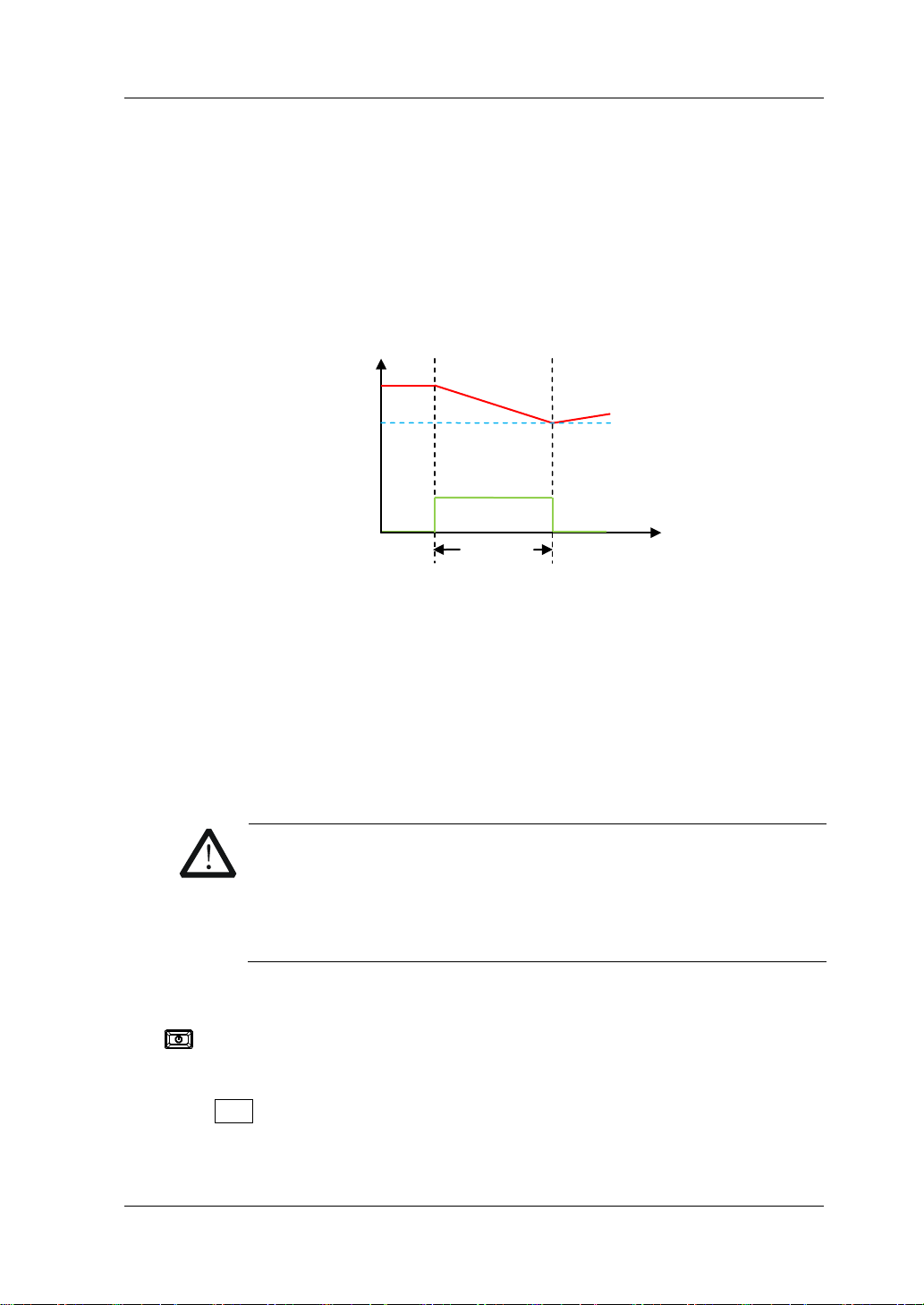
Chapter 2 Front Panel Operations RIGOL
CAUTION
Load Current
Battery Test Function
Battery test principle (as shown in Figure 2-36):
A test for dischar ging the batte ry in C C mode. You can se t the termination condition s:
cut-off voltage value, battery capacity value, and discha rge time . When any one of
the three conditions is met, the discharge stops. Then the load automatically stops
sinking. When only one or two condition(s) is/are selected as the termination
condition(s) for the battery test, set the rest termination condi tions not in use to be
"OFF".
Cut-off V ol t a ge
The battery test can reflect the reliability of the batte ry and the remaining battery lif e.
Therefore,
before replacing the battery, do the battery test first .
Operation Procedures:
1. Connect the b at t ery to the chann el input terminals of the lo ad
Turn off the instrument, as shown in Figure 2-2, connect the battery to the
channel input terminals on the front panel of the load.
V
Battery Voltage
Discharge
Time
Figure 2-36 Battery Test Function
t
While making a connection, the positive polarity of the load should
be connected to the (+) terminal of the channel output, and the
negative polarity of the load to the (-) terminal of the channel
output. A misconnection with the terminals may cause damage to
the instrument or the DUT.
2. Power on the instrument
After the instrument is connected to the power source, press the Power key
on the front panel to power on the instrument.
3. Set channel parameters
Press APP to switch to the main interface of Battery test function, as shown in
Figure 2-37. "Battery" is active at the top of the main interface.
DL3000 User’s Guide 2-59
Page 90

RIGOL Chapter 2 Front Panel Operations
CAUTION
Figure 2-37 Main Interface of Battery Test Function
The parameters for the battery test function include current, range, cut-off
voltage, battery capacity, discha r ge time, and starting voltage.
Set Current
The discharge current. Its default unit is A.
(1) In the main interface, press Current to switch the parameter focus to
"Current".
(2) Enter a value by using the numeric keys, arrow keys, or the knob. For
setting methods, refer to the descriptions of the help inf ormati on or ref er to
the descriptions in "Par a m e te r Setting Me th o d ".
Set Range
Working range for the current in battery test mode. Two ranges are available.
DL3021/DL30 21A: low ra nge (0 to 4 A); hi gh range (0 to 4 0 A)
DL3031/DL3031A: low range (0 to 6 A); high range (0 to 60 A)
(1) In the main interface, press Range to switch the parameter focus to
"Range".
(2) Press Range to switch the current working range. You can also use the
Left/Rig h t arrow key or the knob to switch it.
Note:
The low range provides better resolution and accuracy at low current
settings.
If the set current value is greater than t he maximum v alue of the low range,
you must select a high range.
2-60 DL3000 User’s Guide
Before switching the range, please disable the channel input to
avoid causing damage to the instrument or the battery.
Set V_Stop
When the cut-off voltage is set to the termination condition, after the battery
voltage reaches the cut-off voltage value, the load stops sinking automatically.
The battery stops discharging. The default unit for the cut-off voltage is V.
If you set the cut-off voltage to be the termination condition:
Page 91
Chapter 2 Front Panel Operations RIGOL
Tip
(1) In the main interface, press V_Stop to switch the parameter focus to
"V_Stop".
(2) Press V_Stop to switch to "ON", and select the cut-off voltage to be the
termination condition.
(3) Enter a value by using the numeric keys, arrow keys, or the knob. For
setting methods, refer to the descriptions of the help informat ion or refer to
the descriptions in "Par a m e te r Setting Me th o d ".
If you do not nee d to set the cut-off voltage to be the termination condition:
(1) In the main interface, press V_Stop to switch the parameter focus to
"V_Stop".
(2) Press V_Stop to switch to "O FF", and the input box is disabled, and you are
unable to input any value.
If the cut-off voltage is set to be the termination condition, when the battery
voltage is too low, the system will automatically discontinue test once it
conf irms that the battery reaches the set value.
Set C_Stop
When the battery capacity is set to the termination condition, after the battery
capacity reaches the se t value, the load stops sinki ng automat ically. The battery
stops discharging. The default unit for the value is mAh.
If you set the battery capacity to be the termination condition:
(1) In the main interface, press C_Stop to switch the parameter focus to
"C_Stop".
(2) Press C_Stop to switch to "ON", and select the battery capacity to be the
termination condition.
(3) Enter a value by using the numeric keys, arrow keys, or the knob. For
setting methods, refer to the descriptions of the help informat ion or refer to
the descriptions in "Par a m e te r Setting Me th o d ".
If you do not need to set the battery capacity to be the termination
condition:
(1) In the main interface, press C_Stop to switch the parameter focus to
"C_Stop".
(2) Press C_Stop to swit ch to "OFF", and t he input box i s disabled, and y ou are
unable to input any value.
Set T_Stop
When the discharge time is set to the te rmination condition, after the discharge
time reaches the set value, the load stops sinking automatically. The battery
stops discharging. The default unit for the discharge time is s.
If yo u set the discharge time to be the termination condition:
(1) In the main interface, press T_Stop to switch the parameter focus to
DL3000 User’s Guide 2-61
Page 92

RIGOL Chapter 2 Front Panel Operations
"T_Stop".
(2) Press T_Stop to switch to "ON", and select the discharge time to be the
termination condition.
(3) Enter a value by using the numeric keys, arrow keys, or the knob. For the
setting methods, refer t o t he des criptions of the bui lt -in hel p inf ormatio n or
refer to the descriptions in "Parameter Setting Method".
If you do not need to set the discharge time to be the termination
condition:
(1) In the main interface, press T_Stop to switc h the parameter focus to
"T_Stop".
(2) Press T_Stop to switch to "OFF", and t he input box is disabled, and you a re
unable to input any value.
Set Von
When the input voltage is greater than the set starting voltage (Von), the load
starts to sink the cu rrent. T he def ault unit for Von is V, and it ranges from 0 V to
150 V. The default Von is 0.5 V.
(1) In the main interface, press Von to switch the parameter focus to "Von".
(2) Enter a value by using the numeric keys, arrow keys, or the knob. For
setting methods, refer to the descriptions of the help informat ion or refer to
the descriptions in "Parameter Set tin g Method".
4. Turn on the channel input
Press On/Off to turn on the channel input. At this time, the actual current,
discharge voltage, current discharge time, discharged capacitance, and battery
energy will be displayed in the main interface.
If the termination condition for the battery discharge is met, after completing
the test, a prompt message is displayed, "Battery test completed!" Press OK to
exit.
WARNING
To avoid electric shock, ensure that the battery is connected to the
input terminals of the load properly before you turn on the channel
input.
5. View waveform display
Press the waveform display key
to enter the wa vef orm displa y interfa ce ,
as shown in Figure 2-38. By default, it displa ys the current wav eform . When you
select "I" under "Data", the battery is discharged in CC mode. For detailed
operation, refer to descriptions in "Waveform Display Function". Press the
waveform display key
again to exit the waveform display interface and
return to the main interface of Battery test function.
2-62 DL3000 User’s Guide
Page 93

Chapter 2 Front Panel Operations RIGOL
Figure 2-38 Battery W aveform Di s pl ay Interfa ce
6. Exit the batt e r y test function
Press any key on the front panel of the load to exit the battery test function.
DL3000 User’s Guide 2-63
Page 94

RIGOL Chapter 2 Front Panel Operations
CAUTION
Advanced Function
The advanced functions include factory test function and CC+CV function. Press
Option to enter the advanced function interface, as shown in Figure 2-39
Figure 2-39 Option Interface
Factory Test Function
In CC/CV mode, the load supports the factory test function, whi ch is use d t o te st t he
stability of the current and voltage of the DUT.
Operation Procedures:
1. Connect the DUT and the channel input terminals of the load
Turn off the instrument, as shown in Figure 2-2, connect the DUT and the
channel input terminals on the front panel of the load.
.
2. Power on the instrument
3. Set channel parameters
2-64 DL3000 User’s Guide
While making a connection, the positive polarity of the load should
be connected to the (+) terminal of the channel output, and the
negative polarity of the load to the (-) terminal of the channel
output. A misconnection with the terminals may cause damage to
the instrument or the DUT.
After the instrument is connected to the power source, press the Power key
on the front panel to power on the instrument.
Press Option to enter the advanced function i nterface. Press OK or OK to ent er
the main interface of factory test function, as shown in Figure 2-40. "Factory" is
displayed at the top of the main interface.
Page 95

Chapter 2 Front Panel Operations RIGOL
Figure 2-40 Main Interface of Factory Test F unc tion
The menus of the main interface are displayed in two pages.
Menu items on Page 1: Mode, Current, Range, Max, Min, and Next.
Menu items on Page 2: Pass_Tip, Fail_Tip, Pass_Sound, Fail_Sound, and Back.
To go to t he next page, p r es s Next; to exit the current page and go back to the
previous page, press Back.
Set Mode
Factory test function supports CC/CV mode.
(1) In the main interf ace, press Mode to switch the parameter focus to "Mode".
(2) Press Mode to switch the factory test mode. You can also use the
Left/Right arrow key or the knob to switch it.
Set Current/Voltage
Sets the working voltage or current in the current mode based on the currently
selected working mode for the factory test function. The default unit for the
current is A, and that for the voltage is V.
If you select "CC" mode:
(1) In the main interface, press Current to switch the parameter focus to
"Current".
(2) Enter a value by using the numeric keys, arrow keys, or the knob. For
setting methods, refer to t he descriptions of the help information or ref er to
the descriptions in "Parameter Setting Method".
If you select "CV" mode:
(1) In the main interface, press Voltage to switch the parameter focus to
"Voltage".
(2) Enter a value by using the numeric keys, arrow keys, or the knob. For
setting methods, refer to the descriptions of the help informat ion or ref er to
the descriptions in "Par a m e te r Setting Me th o d ".
Set Range
Sets the range in the current mode based on the currently selected working
mode of the factory test function.
If you select "CC" mode:
DL3000 User’s Guide 2-65
Page 96

RIGOL Chapter 2 Front Panel Operations
CAUTION
(1) In the main interface, press Range to switch the parameter focus to
"Range".
(2) Press Range to switch the current working range. You can also use the
Left/Right arrow key or the knob to switch it.
If you select "CV" mode:
(1) In the main interface, press Range to switch the parameter focus to
"Range".
(2) Press Range to switch the voltage working range. You can also use the
Left/Right arrow key or the knob to switch it.
Note:
The low range provides better resolution and accuracy at low current or
voltage settings.
If the set current or voltage v alue is g reater than the maximum value of the
low range, yo u must select a high range.
Before switching the current range, please disable the channel
input to avoid causing damage to the instrument or the DUT.
Set Max
Sets the upper limit of the working v oltage or cur rent in t he current mo de based
on the currently selected working mode for the factory test function.
(1) In the main interface, press Max to switch the parameter focus to "Max".
(2) Enter a value by using the numeric keys, arrow keys, or the knob. For
setting methods, refer to the descriptions of the help informat ion or refer to
the descriptions in "Par a m e te r Setting Me th o d ".
Set Min
Sets the lower limit of the working v oltage or current in the curre nt mode base d
on the currently selected working mode for the factory test function.
(1) In the main interface, press Min to switch the parameter focus to "Min".
(2) Enter a value by using the numeric keys, arrow keys, or the knob. For
setting methods, refer to t he descriptions of the hel p information or refer to
the descriptions in "Par a m e te r Setting Me th o d ".
Set Pass_Tip
If the test is passed, you can determine whether to display the prompt message
that reports the test pass.
(1) In the main interface, press Pass_Tip to switch the parameter focus to
"Pass_Tip".
(2) Press Pass_Tip to enable or disable the display of the prompt message.
You can also use the Left/Right arrow key or the knob to switch the on/off
state.
2-66 DL3000 User’s Guide
Page 97

Chapter 2 Front Panel Operations RIGOL
WARNING
CAUTION
Set Fail_Tip
If the test is failed, you can determine whether to display the prompt message
that indicates the test failure.
(1) In the main interface, press Fail_Tip to switch the parameter focus to
"Fail_Tip".
(2) Press Fail_Tip to enable or disable the dis play of th e prompt mes sage. Y o u
can also use the Left/Right arrow key or the knob to switch the on/off state .
Set Pass_Sound
If the test is passed, you can determine whether to sound the alarm for test
pass.
(1) In the main interface, press Pass_Sound to switch the parameter focus to
"Pass_Sound".
(2) Press Pass_Sound to enable or disable the alarm sound once the test is
passed. Y ou can also use t he Left/ Right arrow ke y or the knob t o switch the
on/off state.
Set Fail_Sound
If the test is failed, you can determine whether to sound the alarm for test
failure.
(1) In the main interface, press Fail_Sound to switch the parameter focus to
"Fail_Sound".
(2) Press Fail_Sound to enable or disable the alarm sound once the test is
failed. You can also use the Left/Right arrow key or the knob to switch the
on/off state.
4. Turn on the channel input
Press On/Off to turn on the channel input for the factory test function. At this
time, the actual input v oltage, current, resistance, and power will be displa yed in
the main interface.
To avoid electric shock, ensure that the DUT is connected to the
input terminals of the load properly before you turn on the channel
input.
When the fan stops working, the channel is disabled. Then, a
message is displayed, "Fan stops running!"
5. Exit the factory test function
Press any key on the front panel of the load to exit the factory test function.
DL3000 User’s Guide 2-67
Page 98

RIGOL Chapter 2 Front Panel Operations
CAUTION
CC+CV Function
The load supports CC+CV function that simulates two sta ges of chargin g: The load i s
set to be in CC mode and simulates constant current (CC) charging. When the
readback voltage is detected and the detected value reaches the preset voltage, the
load switches to the CV mode to simulate constant voltage (CV) charging. This
function is used to test the charger and similar devices.
Operation Procedures:
1. Connect the DUT and the channel input terminals of the load
Turn off the instrument, as shown in Figure 2-2, connect the DUT and the
channel input terminals on the front panel of the load.
While making a connection, the positive polarity of the load should
be connected to the (+) terminal of the channel output, and the
negative polarity of the load to the (-) terminal of the channel
output. A misconnection with the terminals may cause damage to
the instrument or the DUT.
2. Power on the instrument
After the instrument is connected to the power source, press the Power key
on the front panel to power on the instrument.
3. Set channel parameters
Press Option to enter the advanced function interface, and then use the
Up/Down arrow keys or the knob to switch to "CC+CV". Press OK or OK to
enter the main interface of CC+CV function, as shown in Figure 2-41. "CC+CV"
is displayed at the top of the main interface.
In CC+CV mode, you need to set the following parameters: Current, C_Range,
Voltage, V_Range, V_Limit, and C_Limit.
2-68 DL3000 User’s Guide
Figure 2-41 Main Interface of CC+CV Mode
Page 99

Chapter 2 Front Panel Operations RIGOL
CAUTION
Tip
Tip
Set Current
The constant current in CC+CV mode. The default unit for the current is A.
(1) In the main interface, press Current t o switch the parameter focus to "Current".
(2) Enter a value by using the numeric keys, arrow keys, or the knob. For setting
methods, refer to the descriptions of the help information or refer to the
descriptions in "Parameter Setting Method".
In CC+CV mode, when the set load current is greate r than the cur rent output
from the DUT, short circuit occurs to the DUT.
Set C_Range
The working ranges of current in CC+CV mo de a re as foll ows. Diff erent mo dels ha v e
different ranges.
DL3021/DL3021A: low range (0 to 4 A); high range (0 to 40 A)
DL3031/DL3031A: low range (0 to 6 A); high range (0 to 60 A)
(1) In the main interface, press C_Range to switch the parameter focus to
"C_Range".
(2) Press C_Range to switch the current working range. You can also use the
Left/Right arrow key or the knob to switch it.
Note:
The low range provides better resolution and accuracy at low current settings.
If the set current value is greater than the maximum v alue of the low ran ge, you
must select a high range.
Before switching the current range, please disable the channel
input to avoid causing damage to the instrument or the DUT.
Set Voltage
The constant voltage in CC+CV mode. The default unit for the voltage is V.
(1) In the main interface, pres s Voltage to switch the par ameter focus to "Voltage".
(2) Enter a value by using the numeric keys, arrow keys, or the knob. For setting
methods, refer to the descriptions of the help information or refer to the
descriptions in "Parameter Setting Method".
In CC+CV mode, wh e n th e set load voltage is greater than the voltage
output from the DUT, broken circuit occurs to the DUT.
Set V_Range
Working range for the voltage in CC+CV mode. Two ranges are available: low range
DL3000 User’s Guide 2-69
Page 100
RIGOL Chapter 2 Front Panel Operations
CAUTION
WARNING
CAUTION
(0-15 V) and high ra nge (0-150 V).
(1) In the main interface, press V_Range to switch the parameter focus to
"V_Range".
(2) Press V_Range to switch the voltage working range. You can also use the
Left/Right arrow key or the knob to switch it.
Note:
The low range provides better resolution and accuracy at low voltage settings.
If the set current val ue is greate r than the ma ximum value o f the low range, you
must select a high range.
Before switching the voltage range, please disable the channel
input to avoid causing damage to the instrument or the DUT.
Set V_Limit
The upper limit of the voltage working in CC+CV mode. The default unit for V_Limit
is V, and it ranges from 0 V to 180 V.
(1) In the main interface, p ress V_Limit to switch the parameter focus to " V_Limit".
(2) Enter a value by using the numeric keys, arrow keys, or the knob. For setting
methods, refer to the descriptions of the help information or refer to the
descriptions in "Parameter Setting Method".
Set C_Limit
The upper limit of the current wo rking in CC+C V mode. The default unit for C_Limit is
A, and it rang e s from 0 A to 70 A.
(1) In the main interface, p ress C_Limit to switch the para meter focus to "C_Limit".
(2) Enter a value by using the numeric keys, arrow keys, or the knob. For setting
methods, refer to the descriptions of the help information or refer to the
descriptions in "Parameter Setting Method".
4. Turn on the channel input
Press On/Off to turn on the channel input. At this time, the actual input
voltage, current, resistance, and power will be displayed in the main interface.
2-70 DL3000 User’s Guide
To avoid electric shock, ensure that the DUT is connected to the
input terminals of the load properly before you turn on the channel
input.
When the fan stops working, the channel is disabled. Then, a
message is displayed, "Fan stops running!"
 Loading...