

Page 1
Page 2

Guaranty and Declaration
Copyright
© 2025 RIGOL TECHNOLOGIES CO., LTD. All Rights Reserved.
Trademark Information
RIGOL®is the trademark of RIGOL TECHNOLOGIES CO., LTD.
Notices
• RIGOL products are covered by P.R.C. and foreign patents, issued and pending.
• RIGOL reserves the right to modify or change parts of or all the specifications and pricing
policies at the company's sole decision.
• Information in this publication replaces all previously released materials.
• Information in this publication is subject to change without notice.
• RIGOL shall not be liable for either incidental or consequential losses in connection with the
furnishing, use, or performance of this manual, as well as any information contained.
• Any part of this document is forbidden to be copied, photocopied, or rearranged without prior
written approval of RIGOL.
Product Certification
RIGOL guarantees that this product conforms to the national and industrial standards in China as
well as the ISO9001:2015 standard and the ISO14001:2015 standard. Other international standard
conformance certifications are in progress.
Contact Us
If you have any problem or requirement when using our products or this manual, please contact
RIGOL.
E-mail: [email protected]
Website:
http://www.rigol.com
Page 3
Section Description Page
List of Figures................................................................................................................................IV
List of Tables..................................................................................................................................VI
1 Safety Requirement .........................................................................................................1
1.1 General Safety Summary .................................................................................................................. 1
1.2 Safety Notices and Symbols ............................................................................................................ 3
1.3 Measurement Category .....................................................................................................................3
1.4 Ventilation Requirement ................................................................................................................... 4
1.5 Working Environment ........................................................................................................................4
1.6 Care and Cleaning ............................................................................................................................... 6
1.7 Environmental Considerations ........................................................................................................6
2 Product Features .............................................................................................................. 8
3 Document Overview ....................................................................................................... 9
4 Quick Start ........................................................................................................................11
4.1 General Inspection ............................................................................................................................11
4.2 Appearance and Dimensions ........................................................................................................ 11
4.3 To Prepare for Use .............................................................................................................................12
4.3.1 To Connect to Power ...........................................................................................................12
4.3.2 Turn-on Checkout ................................................................................................................ 13
4.3.3 To Set the System Language ............................................................................................14
4.4 Product Overview ..............................................................................................................................14
4.4.1 Front Panel Overview ..........................................................................................................14
4.4.2 Rear Panel Overview ........................................................................................................... 17
4.4.3 User Interface Overview .................................................................................................... 20
4.5 Touch Screen Gestures .................................................................................................................... 22
4.5.1 Tap ............................................................................................................................................. 22
4.5.2 Drag .......................................................................................................................................... 23
4.6 Parameter Setting Method ............................................................................................................ 23
4.6.1 To Set Parameters with the Front-panel Keys and Knobs ...................................... 23
4.6.2 To Set Parameters with the Touch Screen ....................................................................25
4.7 To Use the Built-in Help System ...................................................................................................29
4.8 To View the Option Information and Install the Option ......................................................29
5 Continuous .......................................................................................................................31
5.1 To Output Sine Wave .......................................................................................................................32
Copyright ©RIGOL TECHNOLOGIES CO., LTD. All rights reserved. DG800 Pro User Guide
I
Page 4
5.2 To Output Square Wave ..................................................................................................................34
5.3 To Output Ramp Wave ....................................................................................................................36
5.4 To Output Pulse ................................................................................................................................. 38
5.5 To Output Noise ................................................................................................................................ 41
5.6 To Output Arbitrary Waveforms ...................................................................................................42
5.7 To Output Harmonic ........................................................................................................................ 50
6 Modulation ...................................................................................................................... 54
6.1 Amplitude Modulation (AM) .........................................................................................................54
6.2 Frequency Modulation (FM) ..........................................................................................................56
6.3 Phase Modulation (PM) .................................................................................................................. 58
6.4 Amplitude Shift Keying (ASK) ....................................................................................................... 59
6.5 Frequency Shift Keying (FSK) ........................................................................................................ 61
6.6 Phase Shift Keying (PSK) .................................................................................................................62
6.7 Pulse Width Modulation (PWM) ..................................................................................................63
6.8 SUM Modulation ............................................................................................................................... 65
7 Sweep .................................................................................................................................67
7.1 Sweep Type ......................................................................................................................................... 67
7.2 Start Frequency and Stop Frequency ......................................................................................... 69
7.3 Center Frequency and Frequency Span .....................................................................................69
7.4 Sweep Time .........................................................................................................................................70
7.5 Start/Stop Hold Time .......................................................................................................................71
7.6 Return Time .........................................................................................................................................71
7.7 Sweep Trigger Source ......................................................................................................................72
7.8 Mark Frequency .................................................................................................................................72
8 Burst ................................................................................................................................... 74
8.1 Burst Type ............................................................................................................................................75
8.2 Burst Delay .......................................................................................................................................... 76
8.3 Burst Phase ..........................................................................................................................................76
8.4 Burst Period .........................................................................................................................................77
8.5 Burst Trigger Source .........................................................................................................................77
8.6 Gated Polarity .....................................................................................................................................78
8.7 Idle Level .............................................................................................................................................. 78
9 Advanced Mode .............................................................................................................80
9.1 Arb ..........................................................................................................................................................81
9.2 Sequence ..............................................................................................................................................82
9.2.1 To Edit Sequence ..................................................................................................................83
9.2.2 To Save/Load Sequence .....................................................................................................84
DG800 Pro User Guide
II
Copyright ©RIGOL TECHNOLOGIES CO., LTD. All rights reserved.
Page 5

9.2.3 To Set Sequence Parameters ............................................................................................85
10 Frequency Counter ........................................................................................................86
10.1 To Enable the Counter .....................................................................................................................87
10.2 To Set the Counter ............................................................................................................................87
10.3 Statistical Function ............................................................................................................................88
11 Channel Copy ..................................................................................................................90
12 Channel Setup .................................................................................................................93
12.1 Sync Signal Setup ..............................................................................................................................93
12.2 Trigger Output Setup .......................................................................................................................95
12.3 Channel Output Setup .....................................................................................................................96
13 Coupling Setup ...............................................................................................................98
14 Align Phase ....................................................................................................................101
15 Storage Management ................................................................................................102
15.1 To Select the File ............................................................................................................................. 102
15.2 To Transfer Files with FTP ............................................................................................................. 103
15.3 To Create New Folder ....................................................................................................................105
15.4 Cut and Copy ................................................................................................................................... 105
15.5 Rename ...............................................................................................................................................105
15.6 Delete ..................................................................................................................................................105
16 Upgrade ..........................................................................................................................106
17 System Utility Function Setting ..............................................................................107
17.1 I/O Setting .........................................................................................................................................107
17.2 LXI .........................................................................................................................................................109
17.3 Basic Settings ................................................................................................................................... 109
17.4 About this Instrument ...................................................................................................................111
17.5 Print Screen .......................................................................................................................................112
17.6 Option .................................................................................................................................................113
17.7 Open Source Acknowledgment .................................................................................................113
17.8 Self-check .......................................................................................................................................... 113
18 Preset Function ............................................................................................................ 114
19 Remote Control ............................................................................................................119
20 Troubleshooting ...........................................................................................................120
21 Appendix ........................................................................................................................ 122
21.1 Appendix A: Options and Accessories .................................................................................... 122
21.2 Appendix B: Warranty ................................................................................................................... 122
Copyright ©RIGOL TECHNOLOGIES CO., LTD. All rights reserved. DG800 Pro User Guide
III
Page 6
List of Figures
Figure 4.1 Front View ..............................................................................................................11
Figure 4.2 Side View ................................................................................................................12
Figure 4.3 Connect to Power ............................................................................................... 13
Figure 4.4 Front Panel ............................................................................................................ 14
Figure 4.5 Rear Panel ..............................................................................................................17
Figure 4.6 User Interface .......................................................................................................20
Figure 4.7 Tap Gesture ........................................................................................................... 23
Figure 4.8 Drag Gesture .........................................................................................................23
Figure 4.9 English Input Interface ......................................................................................26
Figure 4.10 Chinese Input Interface .................................................................................. 27
Figure 4.11 Numeric Keypad ................................................................................................28
Figure 5.1 Continuous Setting Interface ..........................................................................31
Figure 5.2 Harmonic Setting Interface ............................................................................. 51
Figure 5.3 Table Editing Menu .............................................................................................52
Figure 6.1 Modulation Setting Interface ..........................................................................54
Figure 7.1 Sweep Setting Interface ....................................................................................67
Figure 7.2 Linear Sweep .........................................................................................................68
Figure 7.3 Logarithmic Sweep .............................................................................................68
Figure 7.4 Step Sweep ............................................................................................................69
Figure 8.1 Burst Setting Interface ...................................................................................... 74
Figure 9.1 Advanced Waveform Setting Interface ....................................................... 80
Figure 9.2 Arb Setting Interface ..........................................................................................81
Figure 9.3 Sequence Setting Interface ............................................................................. 83
Figure 9.4 Sequence Editing Table .....................................................................................83
Figure 10.1 Counter Menu ....................................................................................................86
Figure 10.2 Counter Statistical Interface ..........................................................................89
Figure 12.1 Channel Setup Interface .................................................................................93
DG800 Pro User Guide
IV
Copyright ©RIGOL TECHNOLOGIES CO., LTD. All rights reserved.
Page 7

Figure 13.1 "Coupling" Menu ..............................................................................................98
Figure 14.1 Before Aligning Phase ..................................................................................101
Figure 14.2 After Aligning Phase ..................................................................................... 101
Figure 15.1 Create Session .................................................................................................104
Figure 18.1 Preset Menu .....................................................................................................114
Copyright ©RIGOL TECHNOLOGIES CO., LTD. All rights reserved. DG800 Pro User Guide
V
Page 8
List of Tables
Table 4.1 Power Adaptor Specifications ...........................................................................13
Table 5.1 Range of Continuous Waveform Frequency ................................................32
Table 5.2 Built-in Waveforms ............................................................................................... 43
Table 11.1 Dual-channel operation parameters ............................................................90
Table 12.1 Sync Signal of Different Output Modes (Positive Polarity) .................. 94
Table 18.1 Factory Settings ................................................................................................ 115
DG800 Pro User Guide
VI
Copyright ©RIGOL TECHNOLOGIES CO., LTD. All rights reserved.
Page 9

Safety Requirement
1
Safety Requirement
1.1 General Safety Summary
Please review the following safety precautions carefully before putting the instrument
into operation so as to avoid any personal injury or damage to the instrument and
any product connected to it. To prevent potential hazards, please follow the
instructions specified in this manual to use the instrument properly.
• Use the BNC Output Connectors Properly.
The front-panel BNC output connectors only allow signal output but unable to
support signal input.
• Use Proper Power Cord.
Only the exclusive power cord designed for the instrument and authorized for
use within the destination country could be used.
• Ground the Product Properly.
The instrument uses the Type-C power interface. The instrument is not grounded
via the power cord. To avoid electric shock, use the ground cable provided in
accessories to connect the instrument to the earth ground before connecting
any input or output terminals.
• Observe All Terminal Ratings.
To avoid fire or shock hazard, observe all ratings and markers on the instrument
and check your manual for more information about ratings before connecting
the instrument.
• Use Proper Overvoltage Protection.
Ensure that no overvoltage (such as that caused by a bolt of lightning) can reach
the product. Otherwise, the operator might be exposed to the danger of an
electric shock.
• Do Not Operate Without Covers.
Do not operate the instrument with covers or panels removed.
• Do Not Insert Objects into the Air Outlet.
Do not insert objects into the air outlet, as doing so may cause damage to the
instrument.
• Avoid Circuit or Wire Exposure.
Do not touch exposed junctions and components when the instrument is
powered on.
• Do Not Operate With Suspected Failures.
Copyright ©RIGOL TECHNOLOGIES CO., LTD. All rights reserved. DG800 Pro User Guide
1
Page 10
Safety Requirement
• Provide Adequate Ventilation.
• Do Not Operate in Wet Conditions.
• Do Not Operate in an Explosive Atmosphere.
If you suspect that any damage may occur to the instrument, have it inspected
by RIGOL authorized personnel before further operations. Any maintenance,
adjustment or replacement especially to circuits or accessories must be
performed by RIGOL authorized personnel.
Inadequate ventilation may cause an increase of temperature in the instrument,
which would cause damage to the instrument. So please keep the instrument
well ventilated and inspect the air outlet and the fan regularly.
To avoid short circuit inside the instrument or electric shock, never operate the
instrument in a humid environment.
To avoid personal injuries or damage to the instrument, never operate the
instrument in an explosive atmosphere.
• Keep Instrument Surfaces Clean and Dry.
To avoid dust or moisture from affecting the performance of the instrument,
keep the surfaces of the instrument clean and dry.
• Prevent Electrostatic Impact.
Operate the instrument in an electrostatic discharge protective environment to
avoid damage induced by static discharges. Always ground both the internal and
external conductors of cables to release static before making connections.
• Use the Battery Properly.
Do not expose the battery (if available) to high temperature or fire. Keep it out of
the reach of children. Improper change of a battery (lithium battery) may cause
an explosion. Use the RIGOL specified battery only.
• Handle with Caution.
Please handle with care during transportation to avoid damage to keys, knobs,
interfaces, and other parts on the panels.
WARNING
Equipment meeting Class A requirements may not offer adequate protection to broadcast
services within residential environment.
DG800 Pro User Guide
2
Copyright ©RIGOL TECHNOLOGIES CO., LTD. All rights reserved.
Page 11
1.2 Safety Notices and Symbols
Safety Notices in this Manual:
WARNING
Indicates a potentially hazardous situation or practice which, if not avoided, will result in
serious injury or death.
CAUTION
Indicates a potentially hazardous situation or practice which, if not avoided, could result
in damage to the product or loss of important data.
Safety Notices on the Product:
• DANGER
Safety Requirement
It calls attention to an operation, if not correctly performed, could result in injury
or hazard immediately.
• WARNING
It calls attention to an operation, if not correctly performed, could result in
potential injury or hazard.
• CAUTION
It calls attention to an operation, if not correctly performed, could result in
damage to the product or other devices connected to the product.
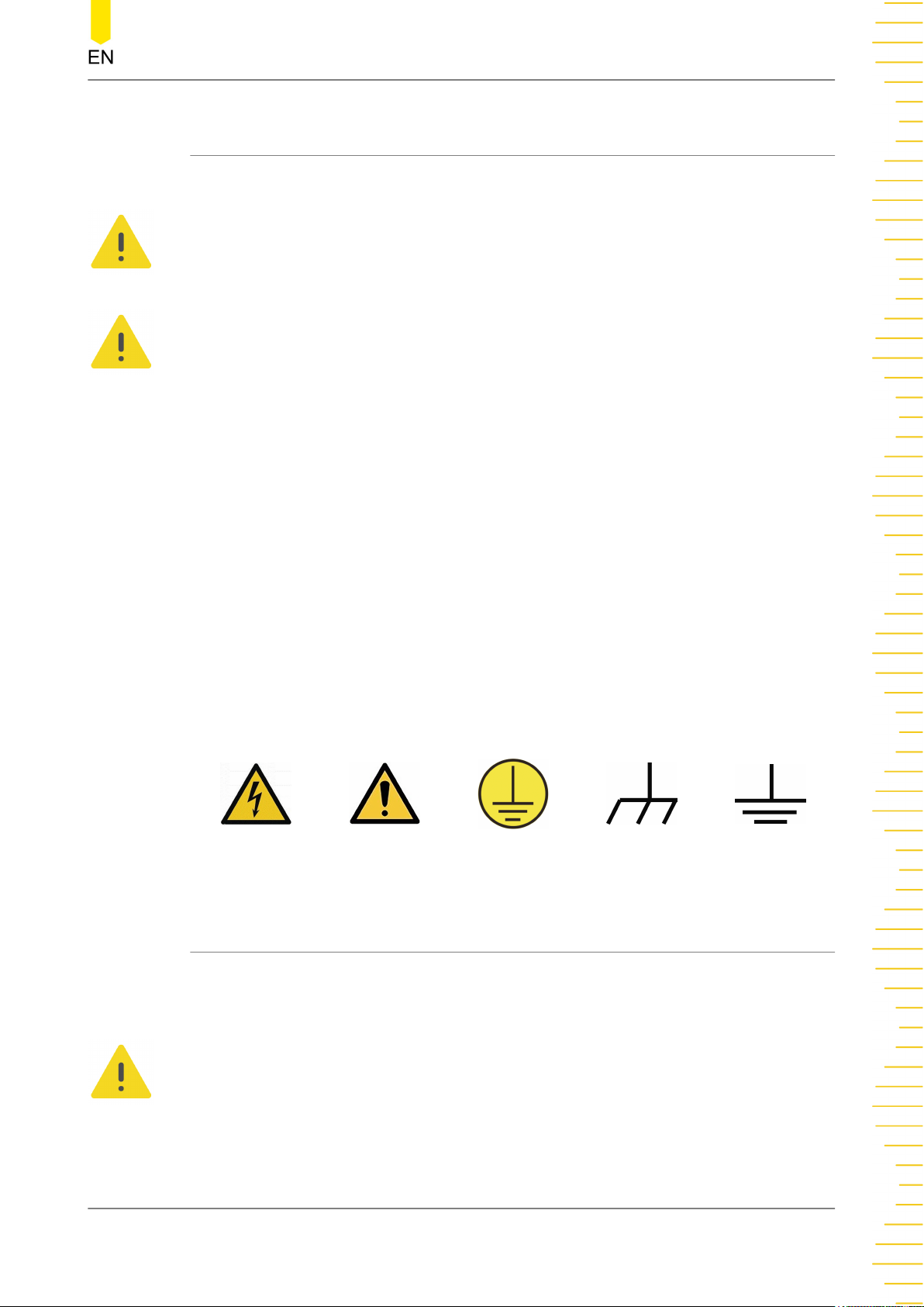
Safety Symbols on the Product:
Hazardous
Voltage
Safety Warning Protective Earth
1.3 Measurement Category
Chassis Ground Test Ground
Terminal
Measurement Category
This instrument can make measurements in Measurement Category I.
WARNING
This instrument can only be used for measurements within its specified measurement
categories.
Copyright ©RIGOL TECHNOLOGIES CO., LTD. All rights reserved. DG800 Pro User Guide
3
Page 12
Safety Requirement
Measurement Category Definitions
• Measurement category I is for measurements performed on circuits not directly
• Measurement category II is for measurements performed on circuits directly
• Measurement category III is for measurements performed in the building
connected to MAINS. Examples are measurements on circuits not derived from
MAINS, and specially protected (internal) MAINS derived circuits. In the latter
case, transient stresses are variable. Thus, you must know the transient withstand
capability of the equipment.
connected to low voltage installation. Examples are measurements on household
appliances, portable tools and similar equipment.
installation. Examples are measurements on distribution boards, circuit-breakers,
wiring (including cables, bus-bars, junction boxes, switches and socket-outlets) in
the fixed installation, and equipment for industrial use and some other
equipment. For example, stationary motors with permanent connection to a
fixed installation.
• Measurement category IV is for measurements performed at the source of a
low-voltage installation. Examples are electricity meters and measurements on
primary overcurrent protection devices and ripple control units.
1.4 Ventilation Requirement
This instrument uses a fan to force cooling. Please make sure that the air inlet and
outlet areas are free from obstructions and have free air. When using the instrument
in a bench-top or rack setting, provide at least 10 cm clearance beside, above and
behind the instrument for adequate ventilation.
CAUTION
Inadequate ventilation may cause an increase of temperature in the instrument, which
would cause damage to the instrument. So please keep the instrument well ventilated and
inspect the air outlet and the fan regularly.
1.5 Working Environment
Temperature
Operating: 0℃ to +40℃
Non-operating: -20℃ to +60℃
Humidity
• Operating:
DG800 Pro User Guide
4
0℃ to +40℃: ≤80% RH (without condensation)
Copyright ©RIGOL TECHNOLOGIES CO., LTD. All rights reserved.
Page 13
Safety Requirement
• Non-operating:
-20℃ to +40℃: ≤90% RH (without condensation)
Below +60℃: ≤80% RH (without condensation)
WARNING
To avoid short circuit inside the instrument or electric shock, never operate the
instrument in a humid environment.
Altitude
• Operating: below 3 km
• Non-operating: below 12 km
Protection Level Against Electric Shock
ESD ±8kV
Installation (Overvoltage) Category
This product is powered by mains conforming to installation (overvoltage) category II.
WARNING
Ensure that no overvoltage (such as that caused by a bolt of lightning) can reach the
product. Otherwise, the operator might be exposed to the danger of an electric shock.
Installation (Overvoltage) Category Definitions
Installation (overvoltage) category I refers to signal level which is applicable to
equipment measurement terminals connected to the source circuit. Among these
terminals, precautions are done to limit the transient voltage to a low level.
Installation (overvoltage) category II refers to the local power distribution level which
is applicable to equipment connected to the AC line (AC power).
Pollution Degree
Pollution Degree 2
Pollution Degree Definition
• Pollution Degree 1: No pollution or only dry, nonconductive pollution occurs.
The pollution has no effect. For example, a clean room or air-conditioned office
environment.
• Pollution Degree 2: Normally only nonconductive pollution occurs. Temporary
conductivity caused by condensation is to be expected. For example, indoor
environment.
Copyright ©RIGOL TECHNOLOGIES CO., LTD. All rights reserved. DG800 Pro User Guide
5
Page 14
Safety Requirement
• Pollution Degree 3: Conductive pollution or dry nonconductive pollution that
becomes conductive due to condensation occurs. For example, sheltered
outdoor environment.
• Pollution Degree 4: The pollution generates persistent conductivity caused by
conductive dust, rain, or snow. For example, outdoor areas.
Safety Class
Class 2
1.6 Care and Cleaning
Care
Do not store or leave the instrument where it may be exposed to direct sunlight for
long periods of time.
Cleaning
Clean the instrument regularly according to its operating conditions.
1. Disconnect the instrument from all power sources.
2. Clean the external surfaces of the instrument with a soft cloth dampened with mild
detergent or water. Avoid having any water or other objects into the chassis via the
heat dissipation hole. When cleaning the LCD, take care to avoid scarifying it.
CAUTION
To avoid damage to the instrument, do not expose it to caustic liquids.
WARNING
To avoid short-circuit resulting from moisture or personal injuries, ensure that the
instrument is completely dry before connecting it to the power supply.
1.7 Environmental Considerations
The following symbol indicates that this product complies with the WEEE Directive
2012/19/EU.
The equipment may contain substances that could be harmful to the environment or
human health. To avoid the release of such substances into the environment and
avoid harm to human health, we recommend you to recycle this product
DG800 Pro User Guide
6
Copyright ©RIGOL TECHNOLOGIES CO., LTD. All rights reserved.
Page 15

Safety Requirement
appropriately to ensure that most materials are reused or recycled properly. Please
contact your local authorities for disposal or recycling information.
You can click on the following link
https://int.rigol.com/services/services/declaration
to download the latest version of the RoHS&WEEE certification file.
Copyright ©RIGOL TECHNOLOGIES CO., LTD. All rights reserved. DG800 Pro User Guide
7
Page 16
Product Features
2
Product Features
Product Features
• Max. sample rate: 625 MSa/s
• Max. output frequency: 50 MHz
• 16-bit vertical resolution
• Arbitrary waveform editing function with a max. Arb waveform length of 2
Mpts/CH (8 Mpts/CH optional)
• Built-in high-order harmonic generator (max. 20th order)
• Independent signal frequency measurement channel with a max. frequency of
500 MHz
• USB and LAN interfaces for remote connection
• Type-C power interface for powering the instrument with mobile power source,
satisfying testing requirements in the field
• Standard Web Control function for easier remote cooperation
DG800 Pro series Function/Arbitrary Waveform Generator provides up to 625 MSa/s
sample rate and 2 Mpts/CH memory depth (standard). It is a cost-effective function/
arbitrary waveform generator that combines multiple functions including Function
Generator, Arbitrary Waveform Generator, Noise Generator, Pulse Generator,
Harmonic Generator, Analog/Digital Modulator and Counter.
DG800 Pro User Guide
8
Copyright ©RIGOL TECHNOLOGIES CO., LTD. All rights reserved.
Page 17
Document Overview
3
Document Overview
This manual gives you a quick overview of the front and rear panels, user interface as
well as basic operation methods of DG800 Pro series function/arbitrary waveform
generator.
TIP
For the latest version of this manual, download it from RIGOL official website (
Publication Number
UGB14102-1110
Software Version
00.02.01
Software upgrade might change or add product features. Please acquire the latest
version of the manual from RIGOL website or contact RIGOL to upgrade the software.
Format Conventions in this Manual
www.rigol.com
).
1. Key
The front panel key is denoted by the menu key icon. For example,
indicates the "Default" key.
2. Menu
The menu item is denoted by the format of "Menu Name (Bold) + Character
Shading" in the manual, for example,
3. Operation Procedures
The next step of the operation is denoted by ">" in the manual. For example,
> Utility indicates first clicking or tapping and then clicking or tapping Utility.
Content Conventions in this Manual
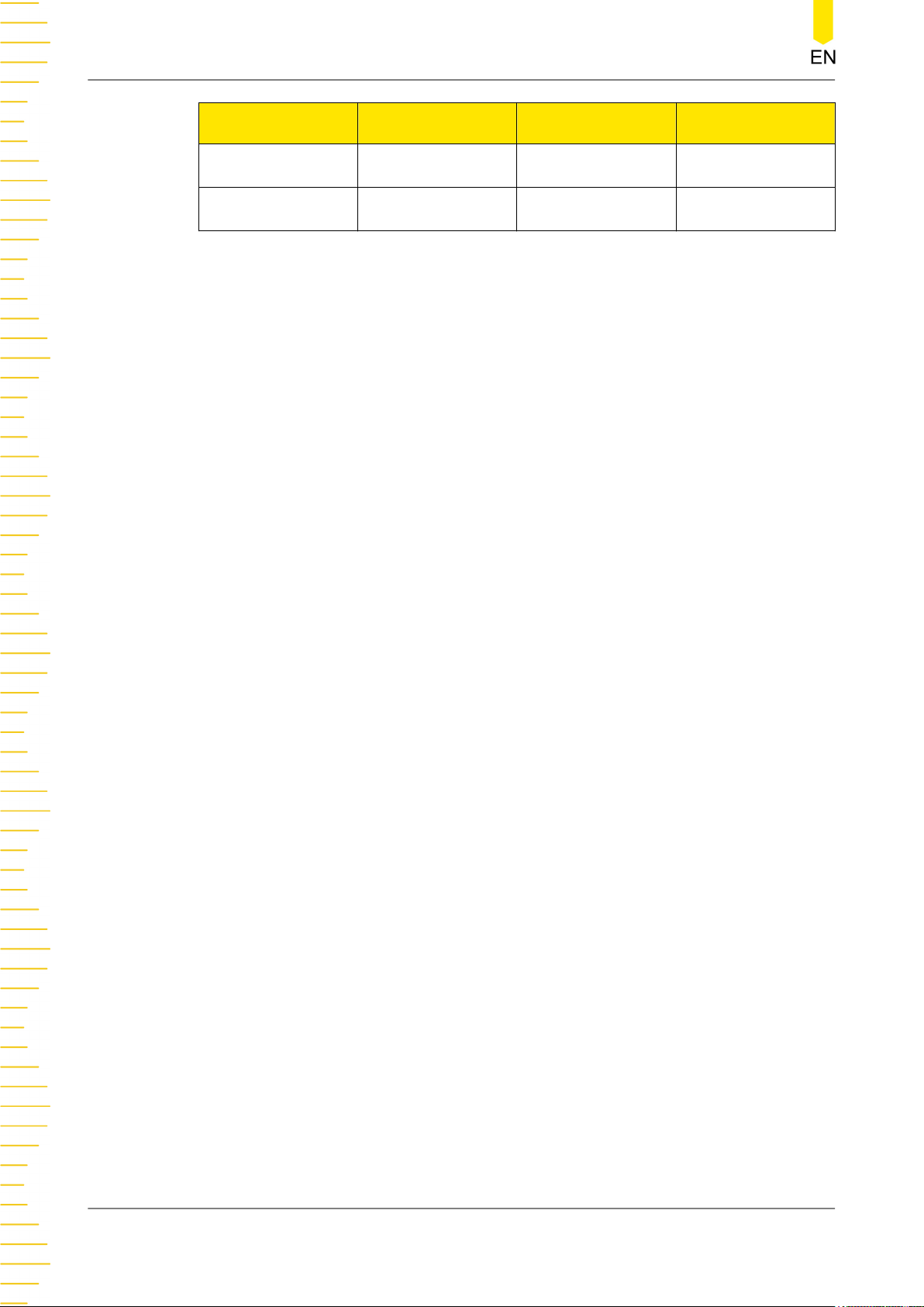
DG800 Pro series function/arbitrary waveform generator includes the following
models. Unless otherwise specified, this manual takes the two-channel model DG852
Pro as an example to illustrate the functions and operation methods of DG800 Pro
series.
Setup.
Model No. of Channels Sample Rate
DG821 Pro 1 625 MSa/s 25 MHz
Copyright ©RIGOL TECHNOLOGIES CO., LTD. All rights reserved. DG800 Pro User Guide
Max. Output
Frequency
9
Page 18
Document Overview
Model No. of Channels Sample Rate
Max. Output
Frequency
DG822 Pro 2 625 MSa/s 25 MHz
DG852 Pro 2 625 MSa/s 50 MHz
DG800 Pro User Guide
10
Copyright ©RIGOL TECHNOLOGIES CO., LTD. All rights reserved.
Page 19
Quick Start
4
Quick Start
4.1 General Inspection
1. Inspect the packaging
If the packaging has been damaged, do not dispose the damaged packaging or
cushioning materials until the shipment has been checked for completeness and
has passed both electrical and mechanical tests.
The consigner or carrier shall be liable for the damage to the instrument resulting
from shipment. RIGOL would not be responsible for free maintenance/rework or
replacement of the instrument.
2. Inspect the instrument
In case of any mechanical damage, missing parts, or failure in passing the electrical
and mechanical tests, contact your RIGOL sales representative.
3. Check the accessories
Please check the accessories according to the packing lists. If the accessories are
damaged or incomplete, please contact your RIGOL sales representative.
Recommended Calibration Interval
RIGOL suggests that the instrument should be calibrated every 12 months.
4.2 Appearance and Dimensions
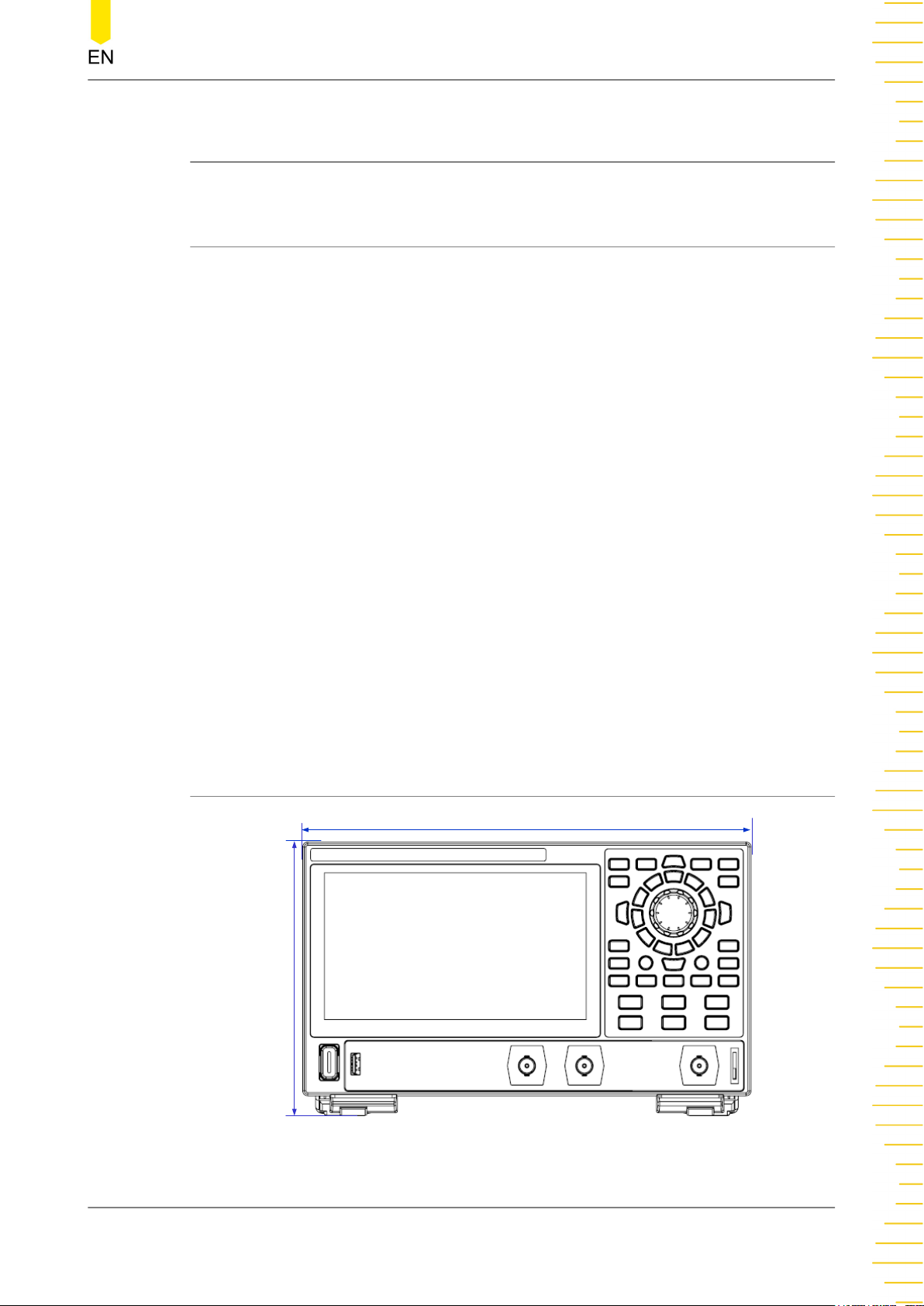
266 mm
165 mm
Figure 4.1 Front View
Copyright ©RIGOL TECHNOLOGIES CO., LTD. All rights reserved. DG800 Pro User Guide
11
Page 20
Quick Start
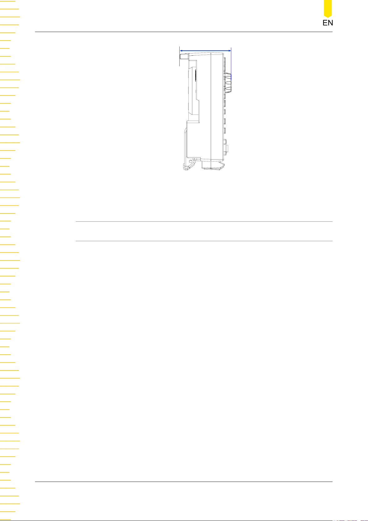
80 mm
Figure 4.2 Side View
4.3 To Prepare for Use
4.3.1 To Connect to Power
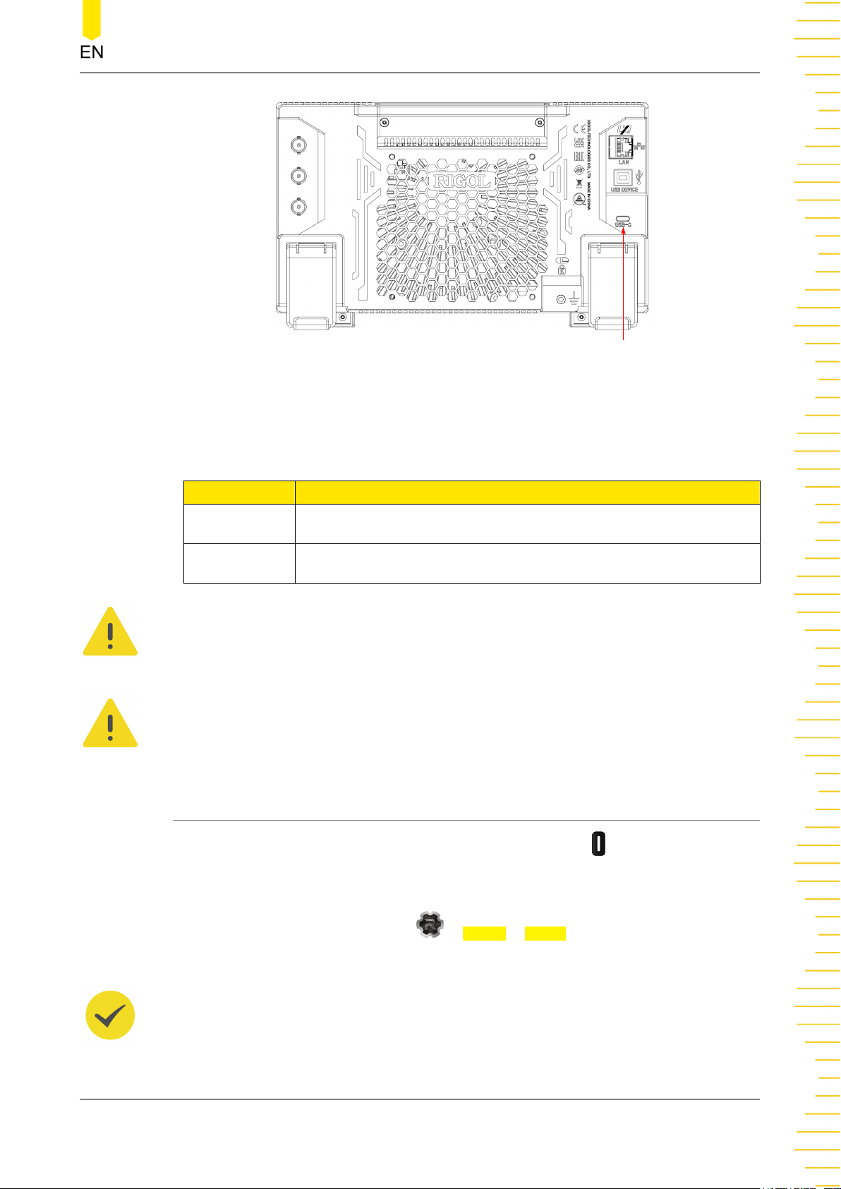
The power requirements of this signal source are USB PD 15 V, 3 A. Please use the
power adaptor provided in the accessories to connect the instrument to the AC
power source (100 V to 240 V, 50 Hz to 60 Hz), as shown in the figure below. Apart
from the instrument's standard power adaptor, this instrument also supports the
power adaptor that conforms to the PD (Power Delivery) protocol. However, the
adaptor should support 15 V 3 A 45 W output.
After the power is connected, the backlight of the front-panel power key can have the
following three states:
• Breathing Red: indicates that the instrument is connected to a compliant power
adaptor and is in standby state. At this time, you can press the power key to
power on the instrument.
• Solid Yellow: indicates that the instrument does not detect a compliant power
adaptor and cannot be powered on.
• Solid Green: indicates that the instrument is running normally.
DG800 Pro User Guide
12
Copyright ©RIGOL TECHNOLOGIES CO., LTD. All rights reserved.
Page 21
Power Connector
Figure 4.3 Connect to Power
Quick Start
Table 4.1 Power Adaptor Specifications
Item Description
Input 100 V to 240 V, 50 Hz to 60 Hz, 1.6 A Max
Output USB PD 15 V, 3 A, 45 W
CAUTION
The power adaptor provided in accessories can only be used to power RIGOL instruments.
Do not use it for mobile phone and other devices.
WARNING
To avoid electric shock, please ensure that the instrument is correctly grounded.
4.3.2 Turn-on Checkout
After the instrument is connected to the power source, press at the lower-left
corner of the front panel to power on the instrument. During the start-up process, the
instrument performs a series of self-tests. After the self-test, the splash screen is
displayed. You can also click or tap
> Utility > Setup to set the "Power Set" to
"Auto". The instrument powers on once connected to power.
TIP
You can shut down the instrument in the following ways.
Copyright ©RIGOL TECHNOLOGIES CO., LTD. All rights reserved. DG800 Pro User Guide
13
Page 22
Quick Start
• Click or tap > Shut Down or press the front-panel and a dialog box "Do you
need to shut down the instrument?" is displayed. Click or tap Shut Down to shut down
the instrument.
• Press twice to shut down the instrument.
• Press for three seconds to shut down the instrument.
4.3.3 To Set the System Language
The instrument supports system languages including Chinese and English. You can
click or tap > Utility > Setup to enter the basic settings menu. Then click or tap
the drop-down button of Language to set the system language to Simplified Chinese,
Traditional Chinese, or English.
4.4 Product Overview
This chapter introduces the appearance and dimensions, front and rear panels as well
as the user interface (display) of the DG800 Pro series by taking DG852 Pro as an
example.
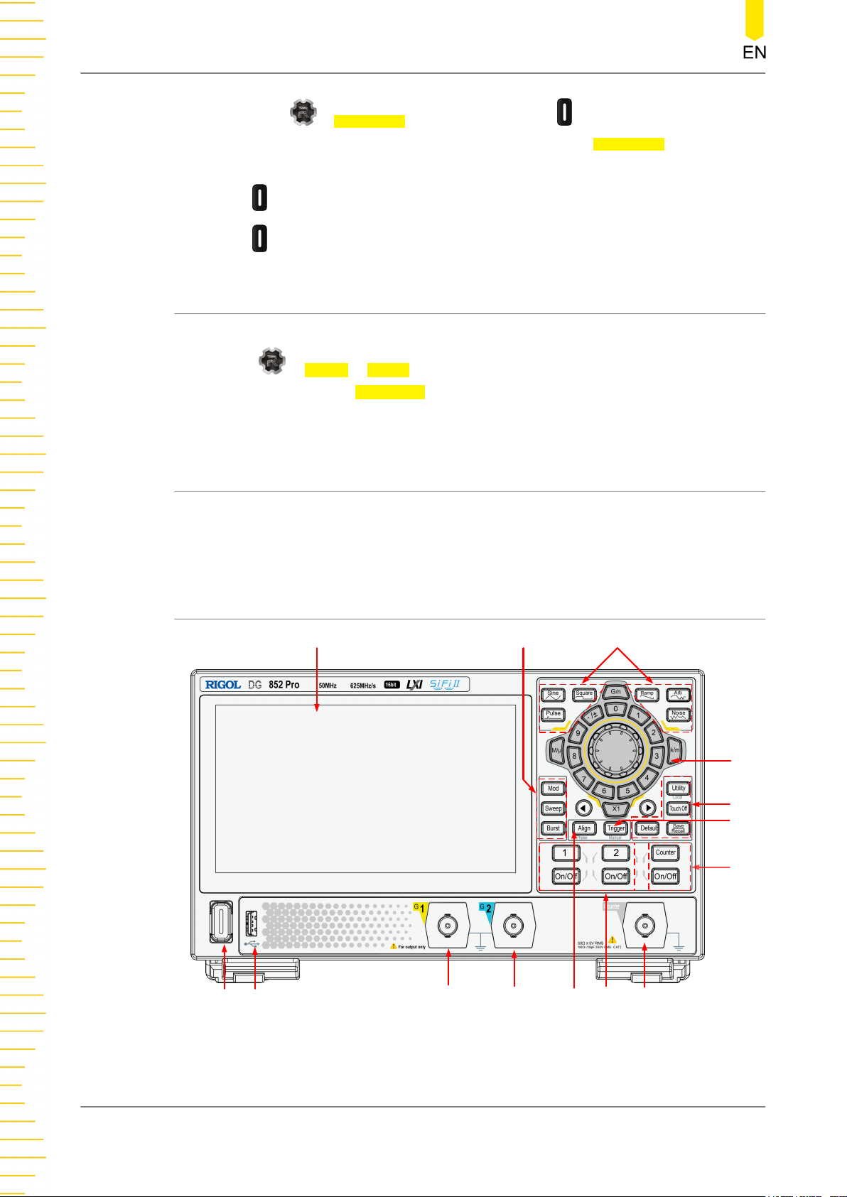
4.4.1 Front Panel Overview
1
2
3
4
5
6
7
DG800 Pro User Guide
14
14
13
12
Figure 4.4 Front Panel
Copyright ©RIGOL TECHNOLOGIES CO., LTD. All rights reserved.
11
10
9
8
Page 23
Quick Start
1. 7-inch Touch Screen
Displays the menu labels, parameter settings, system state, prompt messages, and
other information.
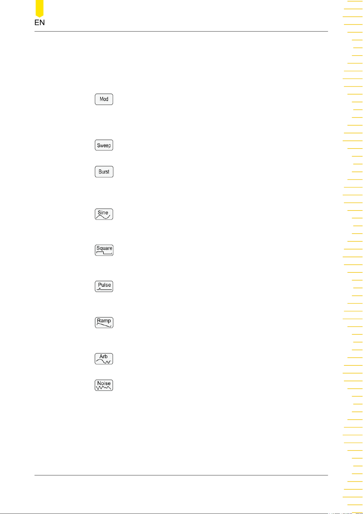
2. Output Mode Selection Area
- : Modulation key. Press the key to set the output mode to Modulation for
the current channel. Available modulated signals include AM, FM, PM, SUM,
ASK, FSK, PSK, and PWM signals. For details about the Modulation mode,
please refer to
- : Sweep key. Press the key to set the output mode to Sweep for the
current channel. For details about the Sweep mode, please refer to
- : Burst key. Press the key to set the output mode to Burst for the current
channel. For details about the Burst mode, please refer to
Modulation
.
Sweep
Burst
.
.
3. Basic Waveform Selection Area
- : Sine key. Press the key to set the basic waveform to Sine for the current
channel. For details about the Sine waveform, please refer to
Wave
.
-
current channel. For details about the Square waveform, please refer to
Output Square Wave
-
current channel. For details about the Pulse waveform, please refer to
Pulse
- : Ramp key. Press the key to set the basic waveform to Ramp for the
current channel. For details about the Ramp waveform, please refer to
Output Ramp Wave
- : Arb key. Press the key to set the basic waveform to Arb for the current
channel. For details about Arb, please refer to
: Square key. Press the key to set the basic waveform to Square for the
.
: Pulse key. Press the key to set the basic waveform to Pulse for the
.
.
To Output Arbitrary Waveforms
To Output Sine
To
To Output
To
.
- : Noise key. Press the key to set the basic waveform to Noise for the
current channel. For details about the Noise, please refer to
4. Parameter Input Area
The parameter input area comprises a knob, a numeric keypad, unit keys, and
arrow keys. For details about the parameter input method, please refer to
Parameter Setting Method
5. Quick Operation Keys
Copyright ©RIGOL TECHNOLOGIES CO., LTD. All rights reserved. DG800 Pro User Guide
.
To Output Noise
.
15
Page 24
Quick Start
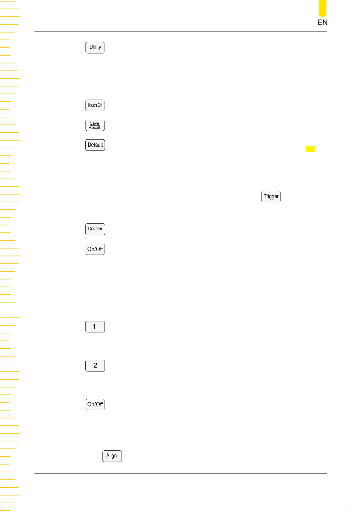
: Utility/Local key. Press the key to enter the system utility function setting
menu to set the remote interface parameters and system functions. You can also
check the instrument information. When the instrument is in remote control mode,
you can press this key to restore the instrument to local operation from remote
control.
: Touch Off key. Press the key to disable or enable the touch screen function.
: Save/Recall key. Press the key to open or close the Store menu.
: Default key. Press the key and a dialog box is displayed. Click or tap OK to
restore the instrument to its factory defaults.
6. Manual Trigger Key
When the instrument is set to manual trigger for Sweep/Burst mode, a sweep/
burst output will be triggered manually each time you press
.
7. Counter Control Area
: Counter menu key. Press the key to open the counter menu.
: Counter On/Off Key. Press the key to enable or disable the Counter
function. When the Counter function is enabled, the backlight of the key is
illuminated; when the Counter function is disabled, the backlight is off.
8. Input Connector for the Signal Measured by Counter
BNC type connector. It is used to accept the signal measured by the counter.
9. Channel Output Control Area
: CH1 selection key. Press the key to select CH1 as the current channel. You
can set the waveforms, parameters and others for CH1 with the front-panel keys
and knob. When CH1 is selected, the backlight of the key is illuminated.
: CH2 selection key. Press the key to select CH2 as the current channel. You
can set the waveforms, parameters and others for CH2 with the front-panel keys
and knob. When CH2 is selected, the backlight of the key is illuminated.
10. Align Key
DG800 Pro User Guide
16
: Channel on/off key. Press the key to enable or disable the corresponding
channel output. When the channel output is enabled, the backlight of the
corresponding key is illuminated.
Press
to align phase. For details, refer to
Copyright ©RIGOL TECHNOLOGIES CO., LTD. All rights reserved.
Align Phase
.
Page 25
Quick Start
11. CH2 Output Connector
BNC type connector with 50 Ω nominal output impedance. When the CH2 output
is enabled, the CH2 output connector outputs the waveform in the current
configuration.
12. CH1 Output Connector
BNC type connector with 50 Ω nominal output impedance. When the CH1 output
is enabled, the CH1 output connector outputs the waveform in the current
configuration.
13. USB HOST Interface
Reads the waveform or state files stored in the USB storage device; saves the
current instrument states or edited waveform data into the USB, or saves the
content displayed on the screen to the USB in the format of a captured image.
FAT32, NTFS, and exFAT formats are supported.
14. Power Key
Powers the signal generator on or off.
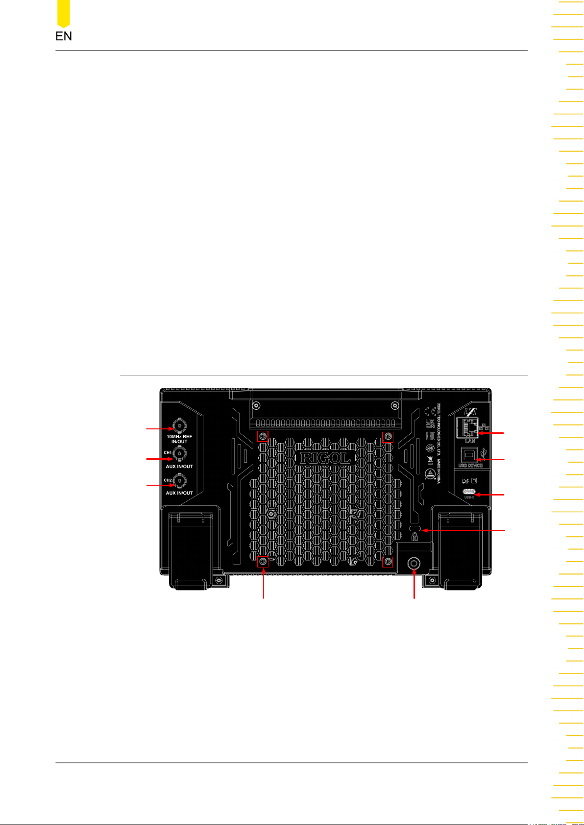
4.4.2 Rear Panel Overview
3
2
1
4
5
6
7
9
Figure 4.5 Rear Panel
1. [CH2 AUX IN/OUT]
BNC female connector. Its function is determined by the current work mode of
CH2.
- Sync output: When the Sync output of CH2 is enabled, this connector outputs
the corresponding sync signal that matches the current configuration of CH2.
Copyright ©RIGOL TECHNOLOGIES CO., LTD. All rights reserved. DG800 Pro User Guide
8
17
Page 26
Quick Start
For details about the characteristics of the sync signals corresponding to various
output signals, please refer to
Sync Signal Setup
.
- Modulation input: when an external modulation source is selected for CH2,
this connector accepts an external modulation signal. For details about external
modulation, please refer to
Modulation
.
- Trigger input: when the Sweep or Burst mode is selected for CH2 and an
external trigger source is selected, this connector accepts an external signal as
the trigger signal of CH2. The polarity of the signal can be set.
- Trigger output: when the Sweep or Burst mode is selected for CH2 and the
trigger output is enabled, this connector outputs a trigger signal with a
specified edge type.
2. [CH1 AUX IN/OUT]
BNC female connector. Its function is determined by the current work mode of
CH1.
- Sync output: When the Sync output of CH1 is enabled, this connector outputs
the corresponding sync signal that matches the current configuration of CH1.
For details about the characteristics of the sync signals corresponding to various
output signals, please refer to
Sync Signal Setup
.
- Modulation input: when an external modulation source is selected for CH1,
this connector accepts an external modulation signal. For details about external
modulation, please refer to
Modulation
.
- Trigger input: when the Sweep or Burst mode is selected for CH1 and an
external trigger source is selected, this connector accepts an external signal as
the trigger signal of CH1. The polarity of the signal can be set.
- Trigger output: When the Sweep or Burst mode is selected for CH1 and the
trigger output is enabled, this connector outputs a trigger signal with a
specified edge type.
3. [10 MHz In/Out]
BNC female connector. Its function is determined by the clock type used by the
instrument.
- When internal clock source is selected, this connector (as 10 MHz Out) outputs
the 10 MHz clock signal generated by the internal crystal oscillator inside the
generator.
4. LAN
DG800 Pro User Guide
18
- When external clock source is selected, this connector (as 10 MHz In) accepts an
external clock signal.
This connector is usually used to synchronize multiple instruments. For clock
source settings, refer to
Basic Settings
.
Copyright ©RIGOL TECHNOLOGIES CO., LTD. All rights reserved.
Page 27

Quick Start
Connect the instrument to network via this interface. The instrument conforms to
LXI CORE 2011 DEVICE instrument standard. Its test system can be built quickly.
Then you can control the instrument by using the Web Control, sending SCPI
commands via PC software, or use the user-defined programming.
5. USB DEVICE
Connect the instrument to the PC via this interface. Then you can use the PC
software to send SCPI commands or use the user-defined programming to control
the instrument.
6. USB Type-C Power Socket
The power requirements of the instrument are USB PD, 15 V, 3 A. Please use the
power adaptor provided in the accessories to connect the instrument to the AC
power source (100 V to 240 V, 50 Hz to 60 Hz).
7. Security Lock Hole
Use a standard PC/laptop lock cable to secure the instrument to a work bench or
other location.
8. Ground Terminal
Connect the instrument chassis to the ground using the lead.
9. Mounting Screw Holes
Interval of screw holes: 100 mm x 100 mm. Use screws (M4*6-10) to secure the
instrument to the bracket with the same screw hole interval.
Copyright ©RIGOL TECHNOLOGIES CO., LTD. All rights reserved. DG800 Pro User Guide
19
Page 28
Quick Start
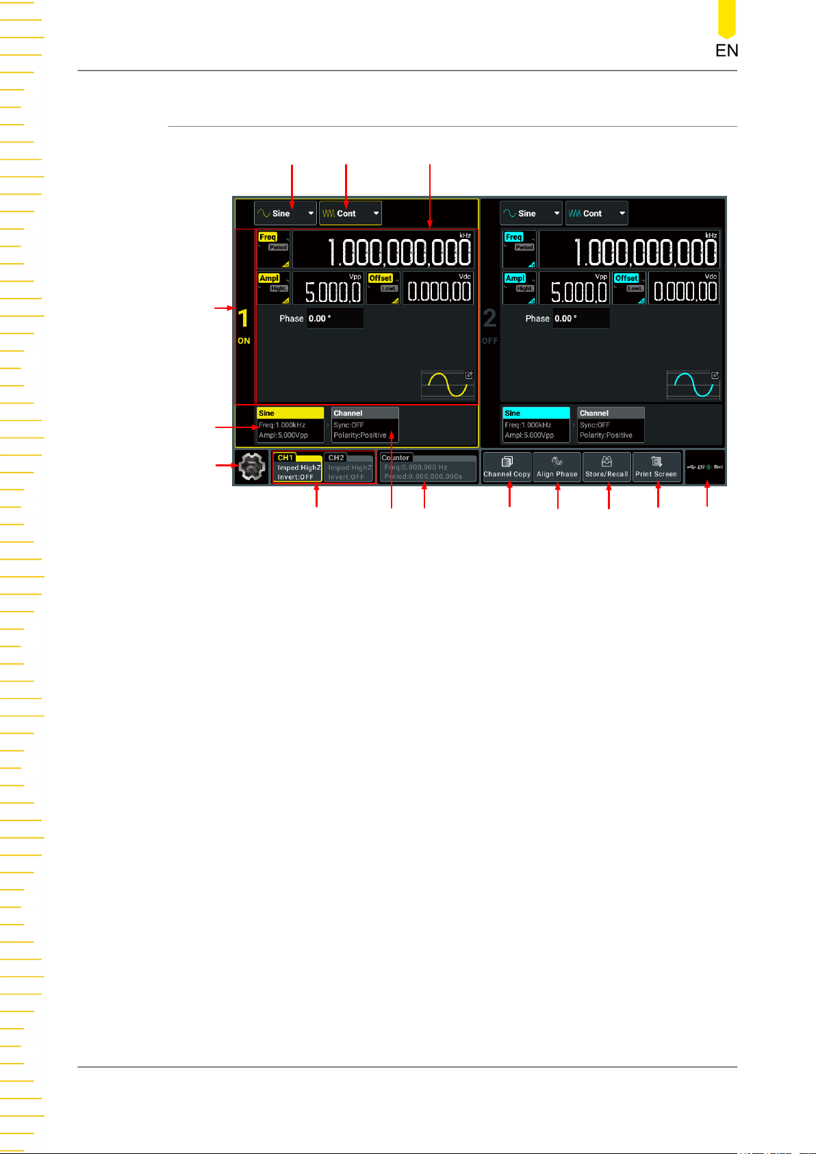
4.4.3 User Interface Overview
14
13
12
11
2
10
1
3
9
8
7
6
45
Figure 4.6 User Interface
1. Wave Type Drop-down Button
Click or tap the drop-down button to select the waveform type for the specified
channel. Available waveform types are related to the current output mode. Note
that the basic waveforms are not available when the output mode is set to
"Advanced".
2. Output Mode Drop-down Button
Click or tap the drop-down button to set the output mode to Continuous,
Modulation, Sweep, Burst, or Advanced for the specified channel.
3. Parameter Configuration Area
You can set the waveform parameters and channel parameters for the
corresponding channel in this area. When the counter is on, the CH2 configuration
area is used to set the counter parameters.
4. Notification Area
Displays the USB icon, LAN icon, sound icon, and remote control icon. You can
click or tap this area to open the "Utility" menu.
DG800 Pro User Guide
20
Copyright ©RIGOL TECHNOLOGIES CO., LTD. All rights reserved.
Page 29
Quick Start
- USB storage device icon: When a USB storage device is detected, will be
displayed.
- LAN icon: When the LAN interface is successfully connected, is displayed.
- Sound icon: In the "Utility" menu, click or tap Setup > Beeper to enable or
disable the sound. When on,
will be displayed; when off, will be
displayed.
- Remote control icon: When the instrument is in remote control mode, will
be displayed.
- Date and Time: When the "Show Time" is set to On, the system date and time
will be displayed.
5. Print Screen Key
Click or tap this key to capture the current screen and save the picture to internal
memory.
6. Store/Recall Key
Click or tap the key to open the storage setting menu.
7. Align Phase Key
Click or tap the key to perform the phase alignment operation. For details, please
refer to
Align Phase
.
8. Channel Copy Key
Click or tap this key to open the channel copy menu. You can copy all states and
waveforms of one channel to the other one. For details, please refer to
Copy
.
Channel
9. Counter Label
Displays the frequency value and period value measured by the counter. When the
counter is turned on, this label is illuminated and displays the frequency and
period measured by the counter.
10. Channel Tab
Displays the sync on/off status and polarity for the corresponding channel. You can
click or tap this tab to switch to the channel setup interface.
11. Channel Labels
Display the channel on/off state (the "CH1"/"CH2" is illuminated or not), the
selected channel (the label is highlighted or not), the impedance, and invert on/off
setting. You can click or tap the label to select the specified channel.
12. Function Navigation Icon
Copyright ©RIGOL TECHNOLOGIES CO., LTD. All rights reserved. DG800 Pro User Guide
21
Page 30
Quick Start
Click or tap the icon to open the function navigation menu in which you can
access the specified function menu by clicking or tapping the corresponding
function key (Utility, Preset, Help, Coupling, Shut Down).
13. Waveform Tab
Displays the selected continuous waveform type, frequency, and amplitude. You
can click or tap this tab to switch to the waveform parameter setting interface.
14. Channel Identifier
Identifies the area as CH1 ("1") or CH2 ("2") and indicates the on/off state of the
channel. You can simply click or tap the area to enable or disable the
corresponding channel output.
4.5 Touch Screen Gestures
The instrument provides a capacitive touch screen, which is convenient for you to
operate and make configurations. It features great convenience, high flexibility, and
great sensitivity. The actions supported by the touch screen controls include tapping
and dragging.
4.5.1 Tap
Use one finger to tap the symbol or characters on the screen slightly, as shown in
Figure 4.7
• Tap the menu displayed on the screen to operate on the menu.
• Tap the function navigation icon at the lower-left corner of the touch screen to
• Tap the displayed numeric keypad to set the parameters.
• Tap the virtual keypad to set the filename.
• Tap the close button at the upper-right corner of the message box to close the
• Tap other windows on the touch screen and operate on the windows.
. With the Tap gesture, you can perform the following operations:
enable the function navigation.
prompt window.
DG800 Pro User Guide
22
Copyright ©RIGOL TECHNOLOGIES CO., LTD. All rights reserved.
Page 31
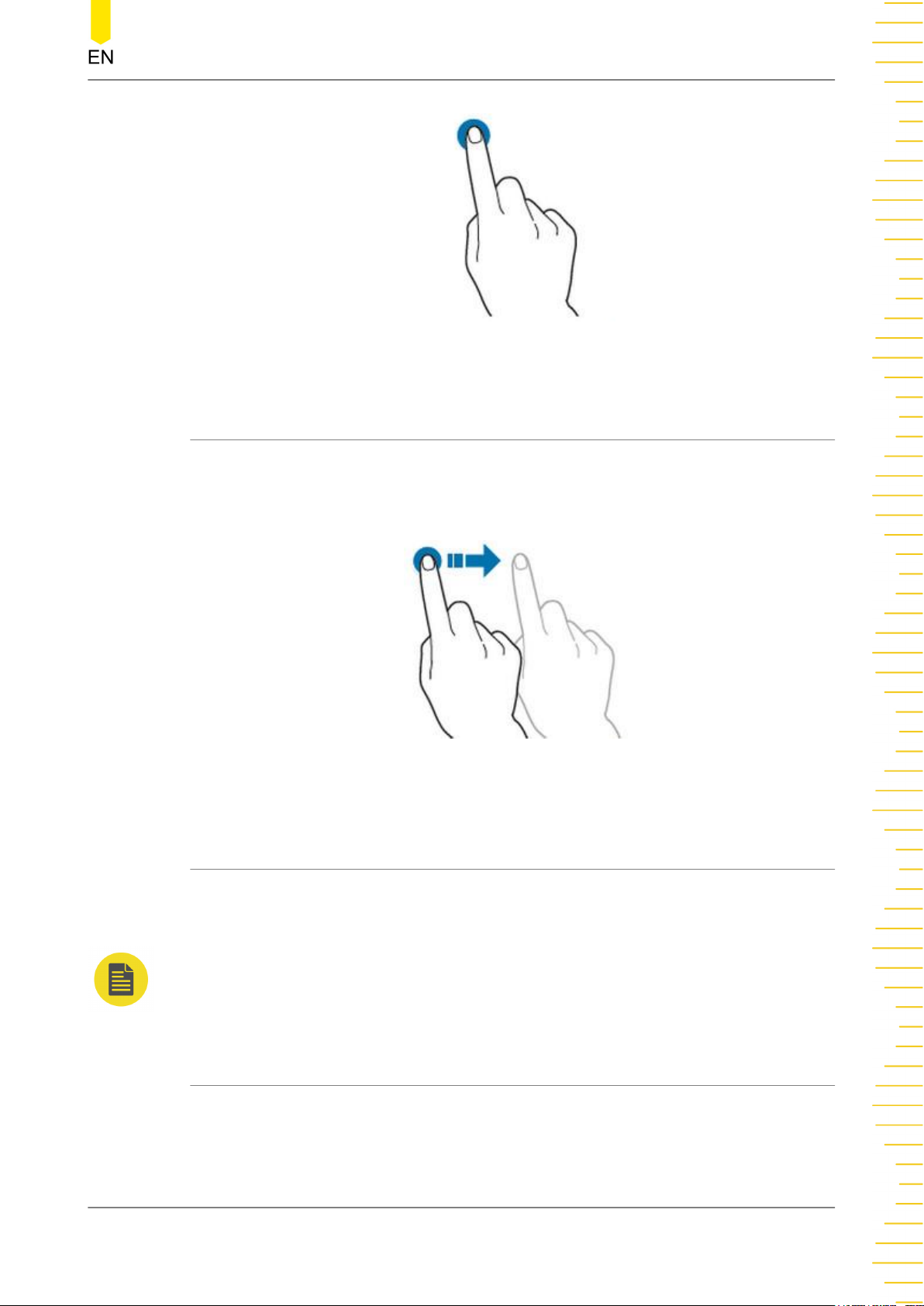
4.5.2 Drag
Use one finger to select the object, and then drag the object to a destination place, as
shown in
window (e.g. numeric keypad).
Figure 4.8
Quick Start
Figure 4.7 Tap Gesture
. You can drag the window controls to change the position of the
Figure 4.8 Drag Gesture
4.6 Parameter Setting Method
This instrument allows you to use the front-panel parameter input area and the touch
screen to set parameters for the instrument.
NOTE
This manual mainly introduces how to set the parameters using the touch screen.
4.6.1 To Set Parameters with the Front-panel Keys and Knobs
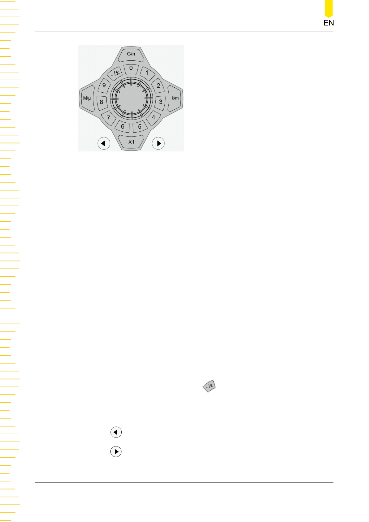
You can use the front-panel parameter input area to set some parameters of the
instrument. The parameter input area consists of a knob, a numeric keypad, unit
selection keys, and arrow keys, as shown in the figure below.
Copyright ©RIGOL TECHNOLOGIES CO., LTD. All rights reserved. DG800 Pro User Guide
23
Page 32
Quick Start
Knob
You can rotate the knob to move the cursor and navigate through the menu items.
Then perform the following operations:
• If the cursor selects a parameter input field, you can press the knob to enter
the parameter editing mode. Then you can use the front-panel arrow keys to
move the cursor to select the digit place to be modified. Rotate the knob
clockwise to increment the value at the selected digit place or counter-clockwise
to decrement the value. Press the knob again to confirm the parameter setting
and disable the parameter editing mode.
• If the cursor selects a drop-down button, you can press the knob to expand
the drop-down menu and then rotate the knob to select a parameter in the
menu. After that, press the knob again to confirm your selection and collapse
the drop-down menu.
• If the cursor selects a key, on/off switch, or tab control, pressing the knob is
equivalent to tapping the corresponding key, on/off switch, or tab control using
the touch screen.
Numeric Keypad
Ring-type numeric keypad composed of numeric keys (from 0 to 9) and the decimal
point/symbol key. If the current cursor selects the input field, you can press the
numeric key to input a number and press
to input ".", "-", or "+". When using the
ring-type numeric keypad, you can also perform the following operations:
• Press the knob to confirm the input.
• Press to delete characters.
• Press
DG800 Pro User Guide
24
to cancel the input.
Copyright ©RIGOL TECHNOLOGIES CO., LTD. All rights reserved.
Page 33
Quick Start
Unit Selection Keys
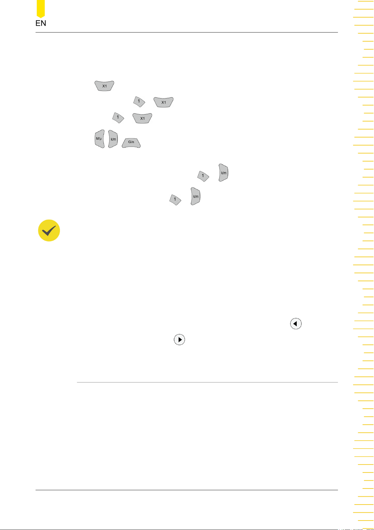
When setting a parameter with the ring-type numeric keypad on the front panel, you
can use the keys to select the unit of the parameter.
• : sets the parameter unit to the default one. For example, when setting the
phase, press > to set the phase to 1°; when setting the frequency,
press
> to set the frequency to 1 Hz.
• / / : when setting the frequency, use the unit (M/k/G) before "/";
when setting time/amplitude/offset, use the unit (μ/m/n) after "/". For example,
when setting the frequency, press > to set the frequency to 1 kHz; when
setting the period, press
> to set the period to 1 ms.
TIP
When the set value exceeds the limit value, the instrument automatically adjusts the parameter
to meet the requirements.
Arrow keys
• In normal mode, you can use the keys to move the cursor to select the desired
menu item. It is equivalent to rotating the knob.
• In parameter editing mode, you can use the keys to select the digit place to be
modified.
• When inputting parameters using the ring-type numeric keypad,
is used to
delete the character while is used to cancel the input and close the input
field.
4.6.2 To Set Parameters with the Touch Screen
For this instrument, you can use the touch screen function to set all of its parameters.
Click or tap the parameter input field and a virtual keypad will be displayed. You can
use the pop-up keypad to complete your parameter setting. The method of using the
virtual keypad is as follows.
Input Chinese and English Characters
For naming a file, this instrument supports both Chinese and English input methods.
The following part introduces how to input Chinese and English characters with the
Chinese/English input method.
Copyright ©RIGOL TECHNOLOGIES CO., LTD. All rights reserved. DG800 Pro User Guide
25
Page 34
Quick Start
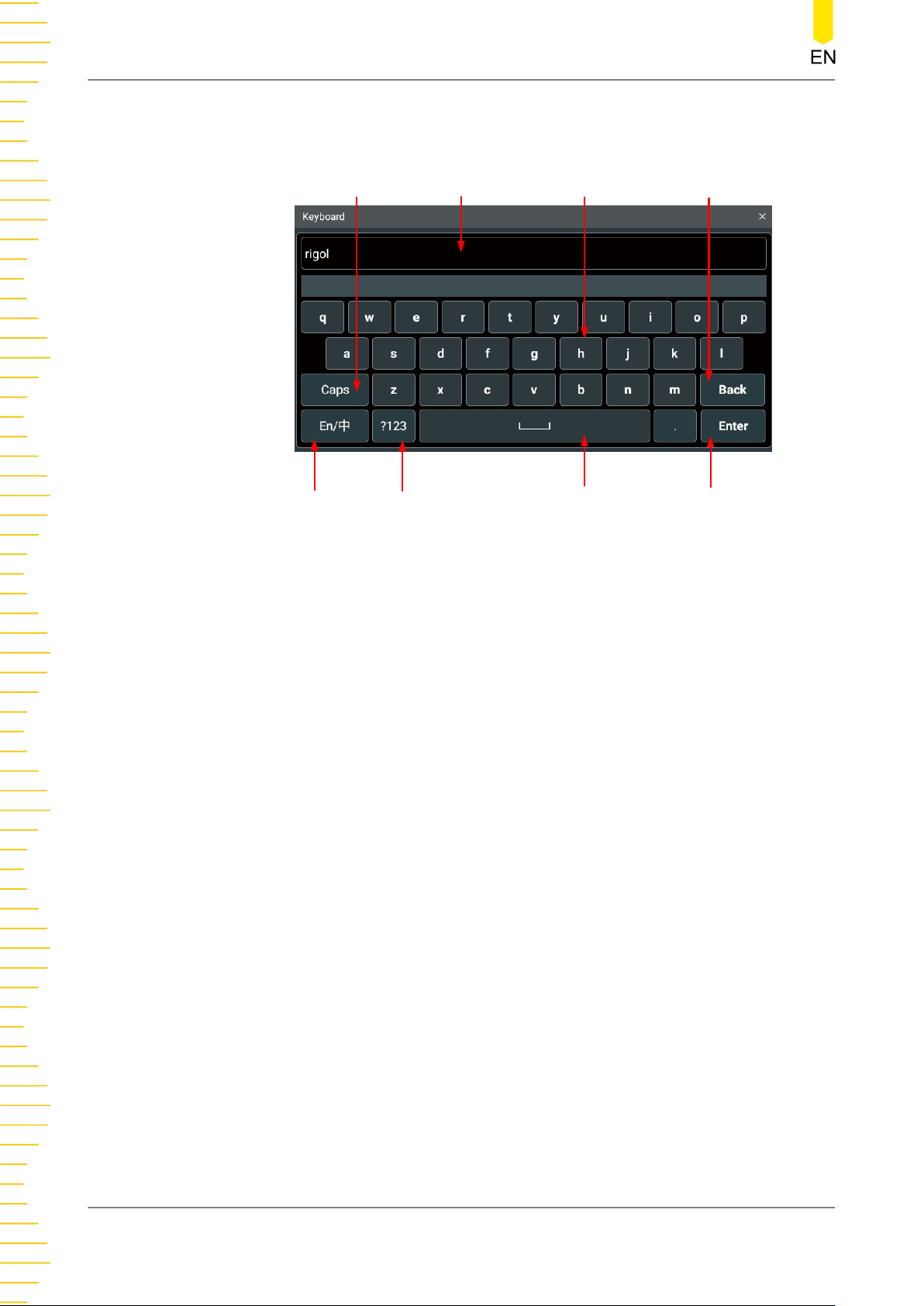
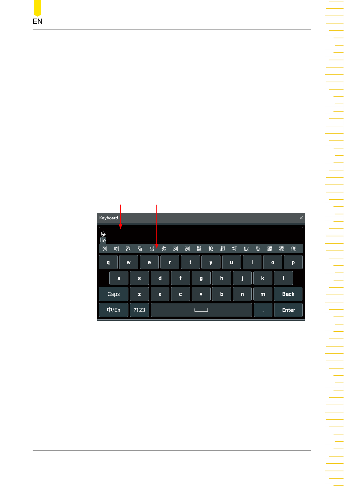
• Input English Characters
Uppercase/Lowercase
Switchover
Input Method
Switchover
Switch to Numbers and
Figure 4.9 English Input Interface
Input Area Virtual Keypad Backspace Key
Space Key
Symbols
Confirm Input
1. Select the English input method
First check the input method type. If it shows "En/中", then go to Step 2; if it
shows "中/En", click or tap the input method switchover key to switch to "En/
中" (English input method).
2. Clear the name input area
If there is no character in the "Input Area", please go to the next step. If there
are characters in the "Input Area", click or tap the "Back" key to delete all the
characters from the "Input Area" in order.
3. Input the upper-case letter
If you want to input an upper-case letter, first use the Caps key to switch
between the upper-case and lower-case modes. If the Caps key is selected,
input the upper-case letter with the virtual keypad. If not, first click or tap the
Caps key to ensure it is selected, then input the upper-case letter. All the input
letters will be displayed in the "Input Area".
4. Input the lower-case letter
Refer to the operation specified in the previous step. If the Caps key is not
selected, directly input the lower-case letter.
DG800 Pro User Guide
26
5. Input numbers or symbols
If the letter keypad is displayed, you need to click or tap the numeric
switchover key to switch to the numeric keypad, and input numbers or
Copyright ©RIGOL TECHNOLOGIES CO., LTD. All rights reserved.
Page 35
Quick Start
symbols with the numeric keypad. All the input letters will be displayed in the
"Input Area".
6. Modify or delete the unwanted characters that have been input
During the name input process, you can modify or delete the unwanted
character if necessary. To delete the characters that have been input, click or
tap the "Back" key in the virtual keypad. To modify the characters that have
been input, delete the unwanted characters first and then input the new
characters.
You can directly move the cursor to the character to be modified or deleted,
delete the desired character or input the new characters after deleting the
unwanted character.
7. Confirm the input
After completing the input operation, click or tap "Enter".
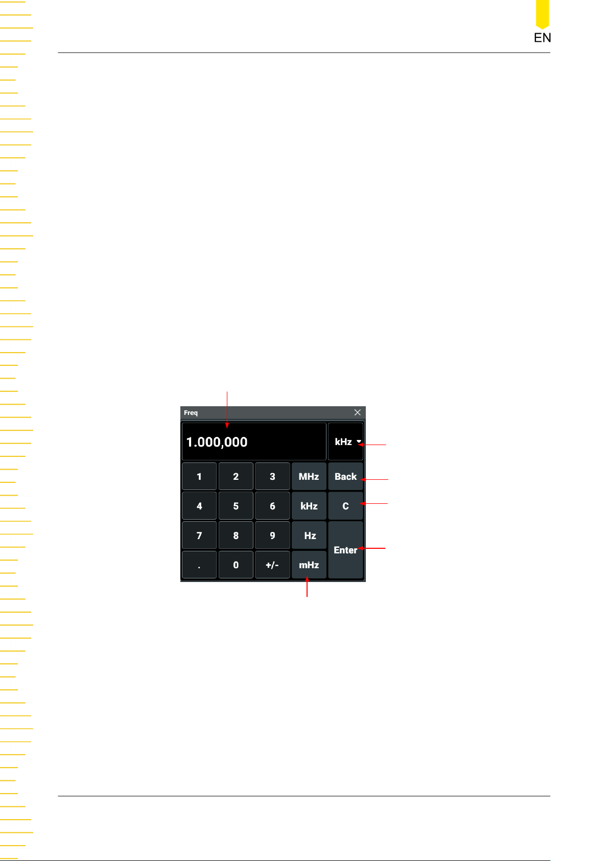
• Input Chinese Characters
Input Area Chinese Character Selection Area
Figure 4.10 Chinese Input Interface
1. Select the Chinese input method
First check the input method type. If it shows "中/En", then go to Step 2; if it
shows "En/中", click or tap the input method switchover key to switch to
"中/En" (Chinese input method).
2. Clear the name input area
If there is no character in the "Input Area", please go to the next step. If there
are characters in the "Input Area", click or tap the "Back" key to delete all the
characters from the "Input Area" in order.
3. Input Chinese characters
Copyright ©RIGOL TECHNOLOGIES CO., LTD. All rights reserved. DG800 Pro User Guide
27
Page 36
Quick Start
Click or tap the virtual keypad to input Pinyin into the input area, then the
characters to be selected will be displayed in the "Chinese Character Selection
Area". Slide to view more Chinese characters for you to choose. Select the
desired Chinese character, and then the selected character will be displayed in
the input area.
4. Modify or delete the unwanted characters that have been input
During the name input process, you can modify or delete the unwanted
character if necessary. To delete the characters that have been input, click or
tap the "Back" key in the virtual keypad. To modify the characters that have
been input, delete the unwanted characters first and then input the new
characters.
5. Confirm the input
After completing the input operation, click or tap "Enter".
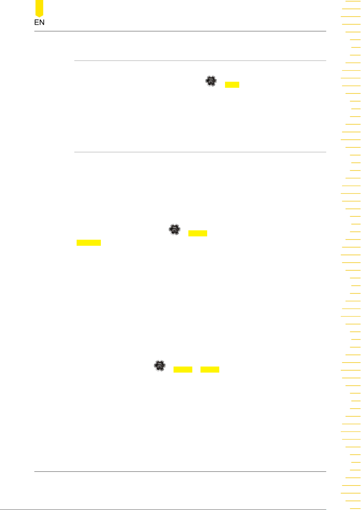
Input a Value
When setting or modifying a function parameter, you can input an appropriate value
with the numeric keypad.
Input Field
Unit Drop-down Button
Back Key
Clear Key
Enter Key
Unit Key
Use the numeric keys in the numeric keypad to input a value. Then select the desired
unit, and the numeric keypad is turned off automatically. This indicates that you have
completed the parameter setting. The unit drop-down menu includes all available
units. You can also click or tap the unit drop-down button to select the desired unit
when multiple units are available. Then click or tap "Enter" to confirm input and close
the numeric keypad.
DG800 Pro User Guide
28
Figure 4.11 Numeric Keypad
Copyright ©RIGOL TECHNOLOGIES CO., LTD. All rights reserved.
Page 37
Quick Start
4.7 To Use the Built-in Help System
The built-in help file provides information about the functions and menu
introductions of the instrument. Click or tap > Help to enter the help system.
In the help system, you can get its help information by clicking on or tapping the link
for the specified chapter.
4.8 To View the Option Information and Install the Option
DG800 Pro provides performance upgrade options to fulfill your measurement
requirements. If you need any of these options, please order them according to the
Order No. available in
options by referring to this section. Besides, you can also view all the options of the
instrument or activate the newly purchased option.
Appendix A: Options and Accessories
, and then install the
View Options
Click or tap the navigation icon > Utility to enter the Utility menu. Click or tap
Options to view the option installation information.
Install the option
The option license is a string of fixed characters. The license file should be in a
specific format, with the filename extension ".lic". After you purchase an option, you
will obtain a key (used for obtaining desired the option license code). Then, you can
install the option according to the following steps.
1. Obtain an option license
a. Log in to the RIGOL official website (
CENTRE > License Activation to enter the software license registration;
b. In the software license registration interface, input the correct key, serial
number (click or tap
instrument), and verification code. Then click Generate to obtain the option
license. If you need to use the file, please download it to the USB storage
device.
> Utility > About to obtain the serial number of the
http://www.rigol.com
), click SERVICE
2. Install the option
You can install the option in the following ways:
- Open the file (*.lic) to obtain the license. Use the :SYSTem:LICense:INSTall
"<License>" command to install the option.
Copyright ©RIGOL TECHNOLOGIES CO., LTD. All rights reserved. DG800 Pro User Guide
29
Page 38
Quick Start
- Save the license file to the USB storage device and connect the USB correctly to
the instrument (you can also save the file to the C disk). Then use
the :SYSTem:LICense:INSTall:UDISk "<path>" command to install the option.
- Save the license file to the USB storage device, connect the USB correctly to the
instrument (you can also save the file to the C disk). Then click or tap
Store/
Recall to open the "Store" menu. Select the license file and then click or tap
Option to install the option.
After installation, a prompt message "Option activated successfully" is displayed.
TIP
• For SCPI commands, refer to
• During the installation process, you are not allowed to power off the instrument.
• You are not allowed to modify the license filename.
DG800 Pro/DG900 Pro Programming Guide
.
DG800 Pro User Guide
30
Copyright ©RIGOL TECHNOLOGIES CO., LTD. All rights reserved.
Page 39
Continuous
5
Continuous
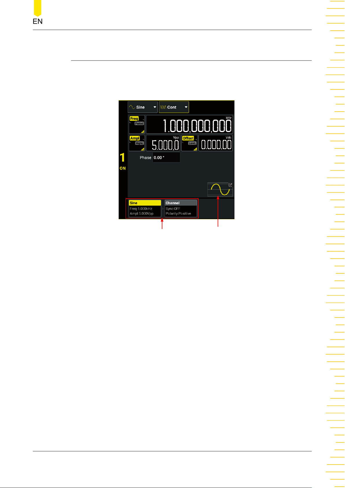
Click or tap the "Output Mode" drop-down button to select "Cont" and configure the
channel to output continuous waveform. The Continuous setting interface is as shown
in the figure below.
Tabs Waveform Preview/Selection
Figure 5.1 Continuous Setting Interface
After setting the output mode to "Cont", you can configure the selected channel to
output the following waveforms and then view the created waveform in the waveform
preview area.
• Sine Wave
• Square Wave
• Ramp Wave
• Pulse
• Noise
• Arbitrary Waveforms
• Harmonic
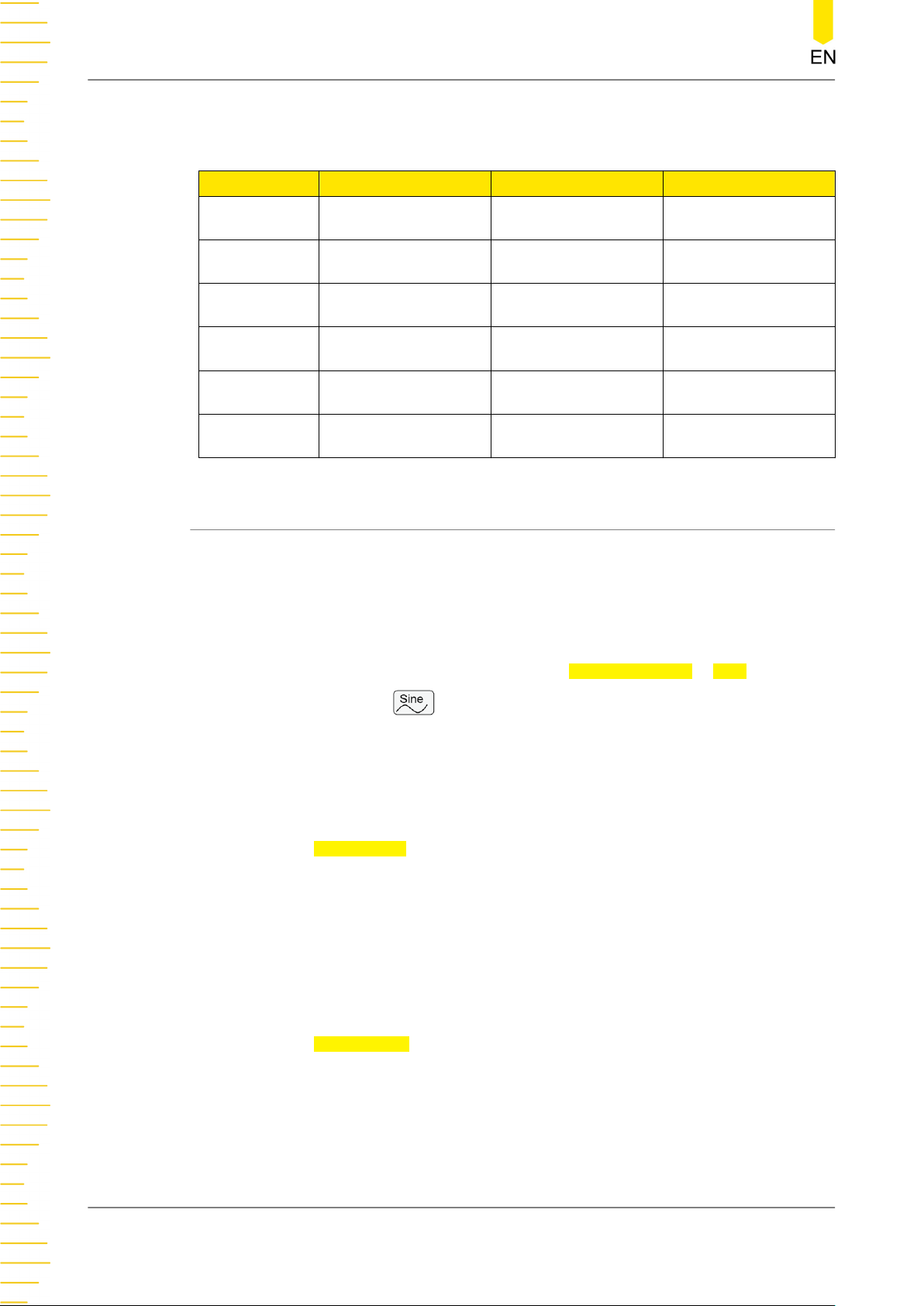
The following table shows the range of the frequency for different waveforms.
Copyright ©RIGOL TECHNOLOGIES CO., LTD. All rights reserved. DG800 Pro User Guide
31
Page 40
Continuous
Table 5.1 Range of Continuous Waveform Frequency
Waveform DG821 Pro DG822 Pro DG852 Pro
Sine 1 μHz to 25 MHz 1 μHz to 25 MHz 1 μHz to 50 MHz
Square 1 μHz to 20 MHz 1 μHz to 20 MHz 1 μHz to 40 MHz
Ramp 1 μHz to 1 MHz 1 μHz to 1 MHz 1 μHz to 1 MHz
Pulse 1 μHz to 10 MHz 1 μHz to 10 MHz 1 μHz to 25 MHz
Standard Arb 1 μHz to 10 MHz 1 μHz to 10 MHz 1 μHz to 15 MHz
Harmonic 1 mHz to 10 MHz 1 mHz to 10 MHz 1 mHz to 25 MHz
5.1 To Output Sine Wave
You can configure the instrument to output sine wave in the following ways.
• In the Continuous Setting Interface (
drop-down button to select "Sine".
• In the Continuous Setting Interface (
Preview/Selection" area and then click or tap
• Press the front-panel key.
In the setting interface for Sine wave, you can set the following parameters to create
different sine waves as desired.
Frequency/Period
Click or tap the
highlighted. Click or tap its input field and use the pop-up numeric keypad to set the
frequency for sine wave. By default, the frequency for sine wave is 1 kHz, and the
resolution is 1 μHz. For available ranges of the sine frequency of different models,
please refer to
tap the button again to toggle the parameter to "Period". Period = 1/Frequency.
Freq/Period button to set the parameter to "Freq". "Freq" is now
Table 5.1 Range of Continuous Waveform Frequency
Figure 5.1
Figure 5.1
Built In Wforms > Sine.
), click or tap the "Wave Type"
), click or tap the "Waveform
. You can click or
Amplitude/High Level
Click or tap the
highlighted. Click or tap its input field and use the pop-up numeric keypad to set the
amplitude for sine wave. Available units for amplitude include Vpp, Vrms, and dBm
(not available in HighZ). The amplitude for sine wave is 5 Vpp by default. Available
range of amplitude is related to the "Impedance" setting.
DG800 Pro User Guide
32
Ampl/HighL button to set the parameter to "Ampl". "Ampl" is now
Copyright ©RIGOL TECHNOLOGIES CO., LTD. All rights reserved.
Page 41
Continuous
• HighZ: 2 mVpp to 20 Vpp.
• Load (50 Ω): 1 mVpp to 10 Vpp.
Click or tap the Ampl/HighL button again to toggle the parameter to "HighL". High
Level = Offset + Amplitude/2. The high level range is related to the low level setting
value. That is, high level minus low level cannot exceed the current range of
amplitude.
NOTE
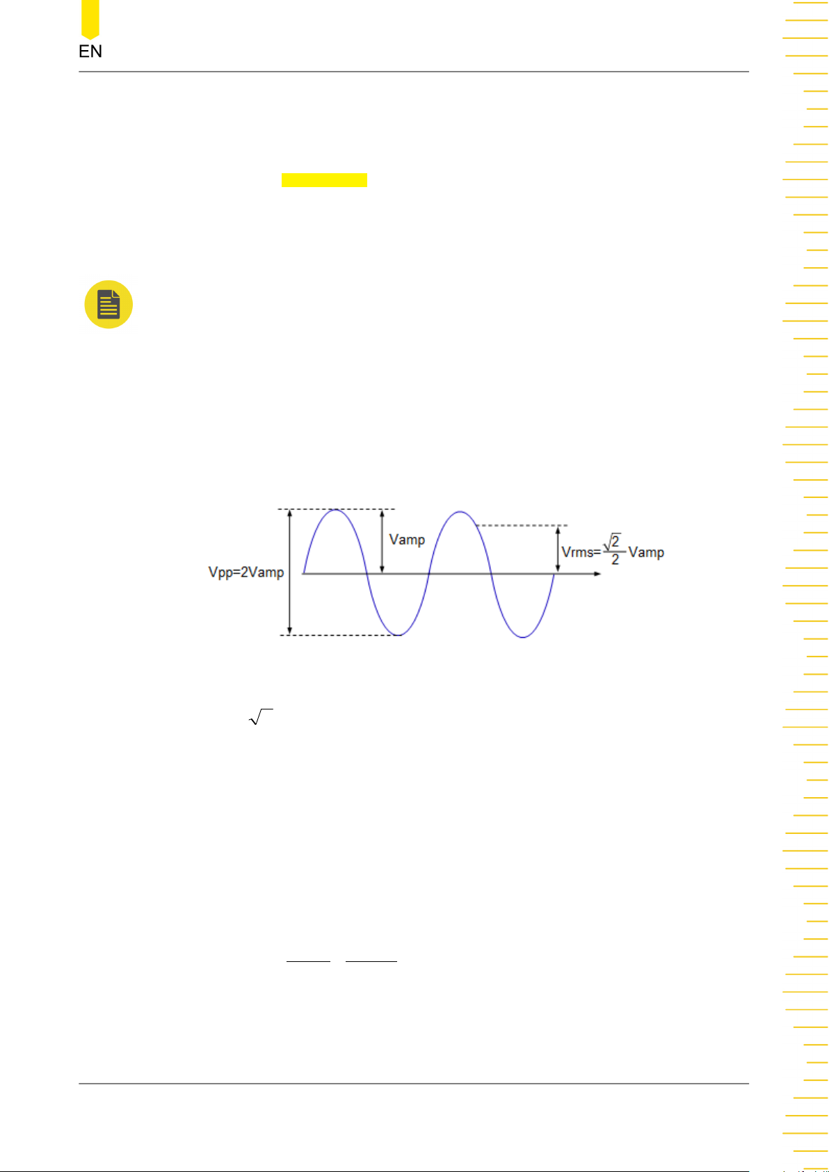
1. How to convert the amplitude in Vpp to the corresponding value in Vrms?
Vpp is the unit for signal peak-peak value and Vrms is the unit for signal effective value. The
default unit is Vpp. When setting the amplitude with the pop-up numeric keypad, you can
click or tap the unit drop-down button to select the desired unit and then click or tap
"Enter" to confirm the current amplitude unit setting. You cannot set the amplitude in dBm
or Vrms for Arb and Harmonic.
The relationship between Vpp and Vrms varies for different waveforms. Take sine wave as
an example. The relationship between the two units is as shown in the figure below.
According to the figure above, the conversion relationship between Sine Vpp and Vrms
fulfills the following equation:
2
V
2. How to set the waveform amplitude in the unit of dBm?
a. Set the impedance to "Load" (refer to
b. When setting the amplitude, click or tap the unit drop-down button to select "dBm" in
the pop-up numeric keypad.
c. Input the desired value and then click or tap "Enter" to set the waveform amplitude in
dBm.
Vrms
2pp =
Impedance
).
dBm is the unit for signal power absolute value. The relationship between dBm and Vrms
fulfills the following equation:
2
dBm
=10 lg (
W is the unit of the signal power. R represents the channel output impedance value which
must be a certain value. Therefore, dBm is not available when the output impedance is set
to "HighZ".
Copyright ©RIGOL TECHNOLOGIES CO., LTD. All rights reserved. DG800 Pro User Guide
Vrms
R
×
0. 001W
1
)
33
Page 42
Continuous
Offset/Low Level
Click or tap the Offset/LowL button to set the parameter to "Offset". "Offset" is now
highlighted. Click or tap its input field and use the pop-up numeric keypad to set the
offset for sine wave. The range of offset is limited by the "Impedance" and
"Amplitude/High Level" setting. The default value is 0 Vdc.
Click or tap the
Level = Offset - Amplitude/2. The low level range is related to the high level setting
value. That is, high level minus low level cannot exceed the current range of
amplitude.
TIP
The "Ampl" and "Offset" buttons appear at the same time, so are "HighL" and "LowL" buttons.
For example, selecting "Offset" automatically toggles the "Ampl/HighL" parameter to "Ampl".
Starting Phase
Click or tap the Phase input field to set the starting phase, which ranges from -360°
to 360°. The default phase is 0°, and the resolution is 0.01°.
Channel Setup
You can also click or tap the "Channel" tab in
channel setup interface to configure channel output. For details, please refer to
Channel Setup
Enable the Channel Output
Offset/LowL button again to toggle the parameter to "LowL". Low
Continuous
.
interface to access the
After setting the waveform parameters, you need to enable the channel to output
waveforms. You can enable the channel output in the following ways.
• Click or tap the channel label at the bottom of the screen.
• Press the front-panel
• Click or tap the channel identifier at the left side of the parameter configuration
area.
key of the corresponding channel.
5.2 To Output Square Wave
You can configure the instrument to output square wave in the following ways.
• In the Continuous Setting Interface (
drop-down button to select "Square".
• In the Continuous Setting Interface (
Preview/Selection" area and then click or tap
• Press the front-panel key.
Figure 5.1
Figure 5.1
Built In Wforms > Square.
), click or tap the "Wave Type"
), click or tap the "Waveform
DG800 Pro User Guide
34
Copyright ©RIGOL TECHNOLOGIES CO., LTD. All rights reserved.
Page 43
Continuous
In the setting interface for Square wave, you can set the following parameters to
create different square waves as desired.
Frequency/Period
Click or tap the Freq/Period button to set the parameter to "Freq". "Freq" is now
highlighted. Click or tap its input field and use the pop-up numeric keypad to set the
frequency for square waveform. By default, the frequency for square is 1 kHz and the
resolution is 1 μHz. For available ranges of the square frequency of different models,
please refer to
Table 5.1 Range of Continuous Waveform Frequency
. You can click or
tap the button again to toggle the parameter to "Period". Period = 1/Frequency.
Amplitude/High Level
Click or tap the
Ampl/HighL button to set the parameter to "Ampl". "Ampl" is now
highlighted. Click or tap its input field and use the pop-up numeric keypad to set the
amplitude for square waveform. Available units for amplitude include Vpp, Vrms, and
dBm (not available in HighZ). For how to set the amplitude in Vrms or dBm, please
refer to
To Output Sine Wave
. The amplitude for square wave is 5 Vpp by default.
Available range of amplitude is related to the "Impedance" setting.
• HighZ: 2 mVpp to 20 Vpp.
• Load (50 Ω): 1 mVpp to 10 Vpp.
Click or tap the
Ampl/HighL button again to toggle the parameter to "HighL". High
Level = Offset + Amplitude/2. The high level range is related to the low level setting
value. That is, high level minus low level cannot exceed the current range of
amplitude.
Offset/Low Level
Click or tap the
Offset/LowL button to set the parameter to "Offset". "Offset" is now
highlighted. Click or tap its input field and use the pop-up numeric keypad to set the
offset for square waveform. The range of offset is limited by the "Impedance" and
"Amplitude/High Level" setting. The default value is 0 Vdc.
Click or tap the
Offset/LowL button again to toggle the parameter to "LowL". Low
Level = Offset - Amplitude/2. The low level range is related to the high level setting
value. That is, high level minus low level cannot exceed the current range of
amplitude.
TIP
The "Ampl" and "Offset" buttons appear at the same time, so are "HighL" and "LowL" buttons.
For example, selecting "Offset" automatically toggles the "Ampl/HighL" parameter to "Ampl".
Starting Phase
Click or tap the
Phase input field to set the starting phase, which ranges from -360°
to 360°. The default phase is 0°, and the resolution is 0.01°.
Copyright ©RIGOL TECHNOLOGIES CO., LTD. All rights reserved. DG800 Pro User Guide
35
Page 44
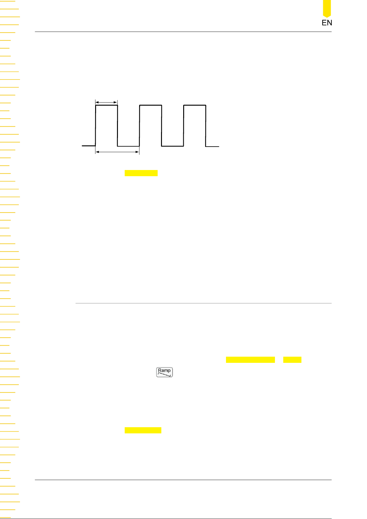
Continuous
Duty Cycle
Duty cycle represents the amount of time per period that the square wave is at a high
level, as shown in the figure below. The "Duty Cycle" parameter setting only appears
when "Square" or "Pulse" is selected.
t
T
Duty Cycle=t/T*100%
Click or tap the Duty Cycle input field to set the duty cycle. The available range is
from 0.01% to 99.99% (depending on the Frequency/Period setting). By default, it is
50%, and the resolution is 0.01%.
Channel Setup
You can also click or tap the "Channel" tab in
Figure 5.1
interface to access the
channel setup interface to configure channel output. For details, please refer to
Channel Setup
.
Enable the Channel Output
Refer to
Enable the Channel Output
of the "To Output Sine Wave" section.
5.3 To Output Ramp Wave
You can configure the instrument to output ramp wave in the following ways.
• In the Continuous Setting Interface (
drop-down button to select "Ramp".
• In the Continuous Setting Interface (
Preview/Selection" area and then click or tap
• Press the front-panel key.
In the setting interface for Ramp wave, you can set the following parameters to create
different ramp waves as desired.
Frequency/Period
Click or tap the
highlighted. Click or tap its input field and use the pop-up numeric keypad to set the
frequency for ramp waveform. By default, the frequency for ramp wave is 1 kHz and
the resolution is 1 μHz. For available ranges of the ramp frequency of different
models, please refer to
Freq/Period button to set the parameter to "Freq". "Freq" is now
Table 5.1 Range of Continuous Waveform Frequency
Figure 5.1
Figure 5.1
Built In Wforms > Ramp.
), click or tap the "Wave Type"
), click or tap the "Waveform
. You can
DG800 Pro User Guide
36
Copyright ©RIGOL TECHNOLOGIES CO., LTD. All rights reserved.
Page 45
Continuous
click or tap the button again to toggle the parameter to "Period". Period = 1/
Frequency.
Amplitude/High Level
Click or tap the Ampl/HighL button to set the parameter to "Ampl". "Ampl" is now
highlighted. Click or tap its input field and use the pop-up numeric keypad to set the
amplitude for ramp wave. Available units for amplitude include Vpp, Vrms, and dBm
(not available in HighZ). For how to set the amplitude in Vrms or dBm, please refer to
To Output Sine Wave
. The amplitude for Ramp wave is 5 Vpp by default. The range of
amplitude is related to the "Impedance" setting.
• HighZ: 2 mVpp to 20 Vpp.
• Load (50 Ω): 1 mVpp to 10 Vpp.
Click or tap the
Ampl/HighL button again to toggle the parameter to "HighL". High
Level = Offset + Amplitude/2. The high level range is related to the low level setting
value. That is, high level minus low level cannot exceed the current range of
amplitude.
Offset/Low Level
Click or tap the
Offset/LowL button to set the parameter to "Offset". "Offset" is now
highlighted. Click or tap its input field and use the pop-up numeric keypad to set the
offset for ramp waveform. The range of offset is limited by the "Impedance" and
"Amplitude/High Level" setting. The default value is 0 Vdc.
Click or tap the
Offset/LowL button again to toggle the parameter to "LowL". Low
Level = Offset - Amplitude/2. The low level range is related to the high level setting
value. That is, high level minus low level cannot exceed the current range of
amplitude.
TIP
The "Ampl" and "Offset" buttons appear at the same time, so are "HighL" and "LowL" buttons.
For example, selecting "Offset" automatically toggles the "Ampl/HighL" parameter to "Ampl".
Starting Phase
Click or tap the Phase input field to set the starting phase, which ranges from -360°
to 360°. The default phase is 0°, and the resolution is 0.01°.
Symmetry
Symmetry is defined as the percentage of the amount of time Ramp wave is rising in
the period, as shown in the figure below. It only appears when "Ramp" is selected.
Copyright ©RIGOL TECHNOLOGIES CO., LTD. All rights reserved. DG800 Pro User Guide
37
Page 46
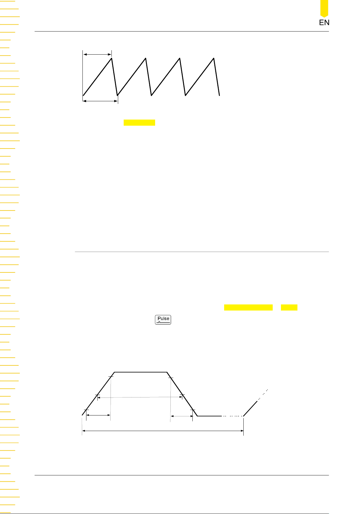
Continuous
t
T
Symmetry=t/T*100%
Click or tap the Symmetry input field to set the symmetry, which ranges from 0.1% to
99.9%. The default value is 50%, and the resolution is 0.1%. In actual use, the
symmetry is limited by the period: 20 ns ≤ Symmetry*Period ≤ Period - 20 ns.
Channel Setup
You can also click or tap the "Channel" tab in
Continuous
interface to access the
channel setup interface to configure channel output. For details, please refer to
Channel Setup
.
Enable the Channel Output
Refer to
Enable the Channel Output
of the "To Output Sine Wave" section.
5.4 To Output Pulse
You can configure the instrument to output Pulse in the following ways.
• In the Continuous Setting Interface (
drop-down button to select "Pulse".
• In the Continuous Setting Interface (
Preview/Selection" area and then click or tap
• Press the front-panel key.
In addition to basic parameters (e.g. Frequency, Amplitude, Offset, Starting Phase,
High Level, Low Level) mentioned before, you also need to set the "Pulse Width/Duty
Cycle", "Rising Edge", and "Falling Edge".
90%
Pulse Width
10%
90%
10%
Figure 5.1
Figure 5.1
Built In Wforms > Pulse.
), click or tap the "Wave Type"
), click or tap the "Waveform
DG800 Pro User Guide
38
Rising Edge
Falling Edge
One Cycle or Period
Copyright ©RIGOL TECHNOLOGIES CO., LTD. All rights reserved.
Page 47
Continuous
Frequency/Period
Click or tap the Freq/Period button to set the parameter to "Freq". "Freq" is now
highlighted. Click or tap its input field and use the pop-up numeric keypad to set the
frequency for pulse waveform. By default, the frequency for Pulse is 1 kHz and the
resolution is 1 μHz. For available ranges of the pulse frequency of different models,
please refer to
Table 5.1 Range of Continuous Waveform Frequency
. You can click or
tap the button again to toggle the parameter to "Period". Period = 1/Frequency.
Amplitude/High Level
Click or tap the Ampl/HighL button to set the parameter to "Ampl". "Ampl" is now
highlighted. Click or tap its input field and use the pop-up numeric keypad to set the
amplitude for pulse waveform. Available units for amplitude include Vpp, Vrms, and
dBm (not available in HighZ). For how to set the amplitude in Vrms or dBm, please
refer to
To Output Sine Wave
. The amplitude for pulse wave is 5 Vpp by default. The
range of amplitude is related to the "Impedance" setting.
• HighZ: 2 mVpp to 20 Vpp.
• Load (50 Ω): 1 mVpp to 10 Vpp.
Click or tap the
Ampl/HighL button again to toggle the parameter to "HighL". High
Level = Offset + Amplitude/2. The high level range is related to the low level setting
value. That is, high level minus low level cannot exceed the current range of
amplitude.
Offset/Low Level
Click or tap the
Offset/LowL button to set the parameter to "Offset". "Offset" is now
highlighted. Click or tap its input field and use the pop-up numeric keypad to set the
offset for pulse waveform. The range of offset is limited by the "Impedance" and
"Amplitude/High Level" setting. The default value is 0 Vdc.
Click or tap the
Offset/LowL button again to toggle the parameter to "LowL". Low
Level = Offset - Amplitude/2. The low level range is related to the high level setting
value. That is, high level minus low level cannot exceed the current range of
amplitude.
TIP
The "Ampl" and "Offset" buttons appear at the same time, so are "HighL" and "LowL" buttons.
For example, selecting "Offset" automatically toggles the "Ampl/HighL" parameter to "Ampl".
Starting Phase
Click or tap the Phase input field to set the starting phase, which ranges from -360°
to 360°. The default phase is 0°, and the resolution is 0.01°.
Copyright ©RIGOL TECHNOLOGIES CO., LTD. All rights reserved. DG800 Pro User Guide
39
Page 48
Continuous
Pulse Width/Duty Cycle
Pulse width is the time from the 50% threshold of a pulse's rising edge to the 50%
threshold of the next falling edge, as shown in the figure above. The pulse duty cycle
is defined as the percentage of the pulse width to the pulse period. Changing one of
them automatically modifies the other.
Click or tap the
Width/Duty button to set the parameter to "Width". "Width" is now
highlighted. Click or tap its input field and use the pop-up numeric keypad to set the
pulse width. The available range is from 9 ns to 999.9 ks. The default value is 500 μs
and the resolution is 0.1 ns.
Click or tap the
Width/Duty button to toggle the parameter to "Duty". Duty Cycle =
Pulse Width/Period. The available range is from 0.01% to 99.99%. The default value is
50% and the resolution is 0.01%.
TIP
• The pulse width must conform to the following restrictions determined by the period and
the minimum pulse width (Wmin: 9 ns): Minimum Pulse Width ≤ Pulse Width ≤ (Period -
Minimum Pulse Width), and Period*0.01% ≤ Pulse Width ≤ Period*99.99%.
• The pulse duty cycle must conform to the following restrictions determined by the
minimum pulse width and pulse period: (Minimum Pulse Width/Period)*100% ≤ Pulse
Duty Cycle ≤ (1 - Minimum Pulse Width/Period)*100%.
Leading/Trailing Edge
The leading (rising) edge time is the time it takes for the pulse level to go from 10%
to 90%; trailing (falling) edge time is the time it takes for the pulse level to go from
90% to 10%.
Click or tap the
Leading/Trailing input field and use the pop-up numeric keypad to
set the leading edge time/trailing edge time. The leading/trailing edge time ranges
from 3 ns to 1 s. The default value is 3 ns and the resolution is 0.1 ns.
TIP
The range of the trailing edge time is limited by the current waveform frequency, pulse width,
and leading edge time. The range of the leading edge time is limited by the current waveform
frequency and pulse width. When the set value exceeds the limits, the instrument will adjust
the edge time automatically.
Channel Setup
You can also click or tap the "Channel" tab in
Continuous
interface to access the
channel setup interface to configure channel output. For details, please refer to
Channel Setup
.
Enable the Channel Output
Refer to
Enable the Channel Output
of the "To Output Sine Wave" section.
DG800 Pro User Guide
40
Copyright ©RIGOL TECHNOLOGIES CO., LTD. All rights reserved.
Page 49
5.5 To Output Noise
You can configure the instrument to output noise in the following ways.
Continuous
• In the Continuous Setting Interface (
drop-down button to select "Noise".
• In the Continuous Setting Interface (
Preview/Selection" area and then click or tap
• Press the front-panel key.
In the setting interface for Noise, you can set the following parameters to create
different noises as desired.
Amplitude/High Level
Click or tap the
highlighted. Click or tap its input field and use the pop-up numeric keypad to set the
amplitude for noise. Available units for amplitude include Vpp, Vrms, and dBm (not
available in HighZ). The amplitude for noise is 4 Vpp by default. The available range is
related to the "Impedance" setting.
• HighZ: 2 mVpp to 4 Vpp.
• Load (50 Ω): 1 mVpp to 2 Vpp.
Ampl/HighL button to set the parameter to "Ampl". "Ampl" is now
Figure 5.1
Figure 5.1
Built In Wforms > Noise.
), click or tap the "Wave Type"
), click or tap the "Waveform
Click or tap the
Level = Offset + Amplitude/2. The high level range is related to the low level setting
value. That is, high level minus low level cannot exceed the current range of
amplitude.
Offset/Low Level
Click or tap the
highlighted. Click or tap its input field and use the pop-up numeric keypad to set the
offset for noise. The range of offset is limited by the "Impedance" and "Amplitude/
High Level" setting. The default offset is 0 Vdc.
Click or tap the
Level = Offset - Amplitude/2. The low level range is related to the high level setting
value. That is, high level minus low level cannot exceed the current range of
amplitude.
TIP
The "Ampl" and "Offset" buttons appear at the same time, and so are "HighL" and "LowL"
buttons. For example, selecting "Offset" automatically toggles the "Ampl/HighL" parameter to
"Ampl".
Ampl/HighL button again to toggle the parameter to "HighL". High
Offset/LowL button to set the parameter to "Offset". "Offset" is now
Offset/LowL button again to toggle the parameter to "LowL". Low
Copyright ©RIGOL TECHNOLOGIES CO., LTD. All rights reserved. DG800 Pro User Guide
41
Page 50
Continuous
Channel Setup
You can also click or tap the "Channel" tab in
Continuous
channel setup interface to configure channel output. For details, please refer to
Channel Setup
.
Enable the Channel Output
Refer to
Enable the Channel Output
of the "To Output Sine Wave" section.
5.6 To Output Arbitrary Waveforms
DG800 Pro supports Arb output in both Continuous mode and Advanced mode. In
the Continuous mode, DG800 Pro outputs waveforms by the traditional DDS method.
The sample rate is fixed to 625 MSa/s and the output frequency is related to the
instrument model (
TIP
If you want to change the sample rate and output the arbitrary waveforms point by point,
switch to the Advanced mode (
Select the Data Source
Table 5.1 Range of Continuous Waveform Frequency
Advanced Mode
).
interface to access the
).
•
Stored Waveforms
In the Continuous Setting Interface (
Preview/Selection" area and then click or tap
Figure 5.1
Stored Wforms in the displayed
), click or tap the "Waveform
menu to open the storage menu. Select the Arb file (*.arb/*.csv/*.txt) that you
want to load from the internal memory (C:) or the external storage device (D:)
and then click or tap
Load. After loading, the data in the current volatile memory
space will change. You can edit the Arb waveform through the PC software and
download it into the instrument. It is recommended to use the PC software Ultra
Station provided by RIGOL. The installation package and help manual of the
software can be obtained from RIGOL official website.
TIP
- The non-advanced output mode only supports arbitrary waveforms with the length
of 16,384 pts.
- DG800 Pro does not support loading Arb files with file headers. It is recommended
to use Ultra Station 00.02.01.00.01 or later to generate Arb waveforms and untick
the "Save File With Header" box when saving the file.
NOTE
DG800 Pro User Guide
42
DG800 Pro supports arb files in *.arb, *.csv, and *.txt formats.
- *.arb files are data files that store binary values.
- *.csv files are voltage data stored in plain text, floating type.
Copyright ©RIGOL TECHNOLOGIES CO., LTD. All rights reserved.
Page 51
- *.txt files are plaintext voltage data (floating) or normalized wave point data
(-32768 to +32767) files separated by separators. Only one data format and
separator can be used in the same file. When loading the *.txt file, select the correct
file data format and data separator in the pop-up sub-menu.
• Built-in Waveforms
Continuous
In the Continuous Setting Interface (
Preview/Selection" area and then click or tap
Figure 5.1
Built In Wforms in the displayed
), click or tap the "Waveform
menu to open the built-in waveform selection menu. You can click or tap
Common, Engine, Seg Mod, Bioelect, Medical, Standard, Maths, Trigonome,
Anti Trigonome, and Window Function to select your desired Arb waveform, as
shown in the table below. The selected waveform type is indicated in Shape in
the Arb setting interface.
Table 5.2 Built-in Waveforms
Name Descriptions
Common
DC DC
Abssine Sine absolute value
Abssinehalf Half-sine absolute value
Ampalt Gain oscillation curve
Attalt Attenuation oscillation curve
Gausspulse Gaussian pulse
Negramp Negative ramp
Npulse Negative pulse
Ppulse Positive pulse
Posramp Positive ramp
Sinetra Sine-Tra waveform
Sinever Sine-Ver waveform
Stair Dn Stair down
Stair Ud Stair up/down
Stair Up Stair up
Trapezia Trapezia
Engineering
2ndosr01 2nd order step response (attenuation
constant: 0.1)
2ndosr02 2nd order step response (attenuation
constant: 0.2)
2ndosr07 2nd order step response (attenuation
constant: 0.7)
2ndoir01 2nd order impulse response (attenuation
constant: 0.1)
2ndoir02 2nd order impulse response (attenuation
constant: 0.2)
Copyright ©RIGOL TECHNOLOGIES CO., LTD. All rights reserved. DG800 Pro User Guide
43
Page 52
Continuous
Name Descriptions
2ndoir07 2nd order impulse response (attenuation
constant: 0.7)
Prbs9 Pseudo-Random Binary Sequence of
order 9
Prbs11 Pseudo-Random Binary Sequence of
order 11
Prbs15 Pseudo-Random Binary Sequence of
order 15
Prbs16 Pseudo-Random Binary Sequence of
order 16
Prbs20 Pseudo-Random Binary Sequence of
order 20
Prbs21 Pseudo-Random Binary Sequence of
order 21
Prbs23 Pseudo-Random Binary Sequence of
order 23
Three Tone Three-tone signal
Four Tone Four-tone signal
Five Tone Five-tone signal
Six Tone Six-tone signal
Seven Tone Seven-tone signal
Eight Tone Eight-tone signal
Bandlimited Band-limited signal
Blaseiwave Time-velocity curve
Butterworth Butterworth filter
Chebyshev1 Type I Chebyshev filter
Chebyshev2 Type II Chebyshev filter
Combin Combination function
Cpulse C-Pulse signal
Cw Pulse CW pulse signal
Damped Osc Damped oscillation time-offset curve
Distortion Distorted waveform
Dampedsine1 Damped sine wave (1 Hz frequency)
Dampedsine3 Damped sine wave (3 Hz frequency)
Dampedsine5 Damped sine wave (5 Hz frequency)
Dualtone Dual-tone signal
Gamma Gamma signal
Gatevibr Gate self-excited oscillating signal
Lfm Pulse Linear frequency modulation pulse signal
LowerSemicircle Lower semicircle
Mcnoise Mechanical noise
Nimh Discharge Discharge curve of NiMH batteries
Neg halfsine Negative half cycle of sine wave
Pos Hwrsine Half wave rectifier of sine (positive)
DG800 Pro User Guide
44
Copyright ©RIGOL TECHNOLOGIES CO., LTD. All rights reserved.
Page 53
Continuous
Name Descriptions
Neg Hwrsine Half wave rectifier of sine (negative)
Pos Fwrsine Full wave rectifier of sine (positive)
Neg Fwrsine Full wave rectifier of sine (negative)
Pahcur DC brushless motor current waveform
Quake Earthquake wave
Radar Radar signal
Ripple Power ripple
Roundhalf Roundhalf waveform
Stepresp Step response signal
Swing Osc
Swing oscillation kinetic energy-time
curve
TV TV signal
Voice Voice signal
Segment Modulation
Three Am Sine piecewise AM waveform
Three Fm Sine piecewise FM waveform
Three Pfm Pulse piecewise FM waveform
Three Pm Sine piecewise PM waveform
Three Pwm Pulse width piecewise FM waveform
Bioelectricity
Cardiac Cardiac signal
Ecg1 Electrocardiogram 1
Ecg2 Electrocardiogram 2
Ecg3 Electrocardiogram 3
Ecg4 Electrocardiogram 4
Ecg5 Electrocardiogram 5
Ecg6 Electrocardiogram 6
Ecg7 Electrocardiogram 7
Ecg8 Electrocardiogram 8
Ecg9 Electrocardiogram 9
Ecg10 Electrocardiogram 10
Ecg11 Electrocardiogram 11
Ecg12 Electrocardiogram 12
Ecg13 Electrocardiogram 13
Ecg14 Electrocardiogram 14
Ecg15 Electrocardiogram 15
Eog Electro-oculogram (EOG)
Eeg Electroencephalo-graph (EEG)
Emg Electromyography (EMG)
Pulsilogram Pulsilogram
Resspeed Speed curve of the respiration
Medical
Copyright ©RIGOL TECHNOLOGIES CO., LTD. All rights reserved. DG800 Pro User Guide
45
Page 54
Continuous
Name Descriptions
Lf Pulse
Tens1
Tens2
Tens3
Low frequency pulse electrotherapy
waveform
Transcutaneous Electric Nerve Stimulation
(TENS) waveform 1
Transcutaneous Electric Nerve Stimulation
(TENS) waveform 2
Transcutaneous Electric Nerve Stimulation
(TENS) waveform 3
Standard
Ignition
Ignition waveform of the automotive
motor
Iso16750 2 Sp Automotive starting profile with ringing
Iso16750 2 Vr
Automotive supply voltage profile for
resetting
Iso16750 2 Vit Voltage discontinuous, variable interrupt
time
Iso16750 2 VRT Voltage discontinuous, variable recovery
time
Iso16750 2 LD1 Transients due to battery disconnect from
the generator
Iso16750 2 LD2 Transients due to battery disconnect from
the generator
Iso7637 2 Tp1 Automotive transients due to disconnects
Iso7637 2 Tp2a
Iso7637 2 Tp2b
Automotive transients due to inductance
in wiring
Automotive transients due ignition
switching off
Iso7637 2 Tp3a Automotive transients due to switching
Iso7637 2 Tp3b Automotive transients due to switching
Iso7637 2 Tp4 Automotive supply profile during starting
Iso7637 2 Tp5a
Iso7637 2 Tp5b
Automotive transients due to battery
disconnect
Automotive transients due to battery
disconnect
Scr SCR firing profile
Surge Surge signal
Maths
Airy Airy function
Airyai AiryAi
Airybi AiryBi
Besselj BesselI function
Bessely BesselII function
Cauchy Cauchy distribution function
Chebyshev3 3rd order Chebyshev polynomial
Chebyshev4 4th order Chebyshev polynomial
Chebyshev5 5th order Chebyshev polynomial
Chebyshev6 6th order Chebyshev polynomial
DG800 Pro User Guide
46
Copyright ©RIGOL TECHNOLOGIES CO., LTD. All rights reserved.
Page 55
Continuous
Name Descriptions
Chebyshev7 7th order Chebyshev polynomial
Chebyshev8 8th order Chebyshev polynomial
Chebyshev9 9th order Chebyshev polynomial
Chebyshev10 10th order Chebyshev polynomial
Clausen Clausen function
Cubic Cubic function
Dirichlet Dirichlet function
Erf Error function
Erfc Complementary error function
Erfcinv Inverted complementary error function
Erfinv Inverted error function
Expfall Exponential fall function
Exprise Exponential rise function
Gabor1 Garbor function 1
Gabor3 Garbor function 3
GammaInv Inverse Gamma function
Gauss
Gaussian distribution (also known as
normal distribution)
Gaussderiv Gaussian derivative
Gausshermite1 Gauss-Helmert function 1
Gausshermite2 Gauss-Helmert function 2
Gausshermite3 Gauss-Helmert function 3
Gausshermite4 Gauss-Helmert function 4
Haversine HaverSine function
Laguerre Laguerre polynomial
Laguerre2 2nd order Laguerre polynomial
Laguerre3 3rd order Laguerre polynomial
Laguerre4 4th order Laguerre polynomial
Laguerre5 5th order Laguerre polynomial
Laguerre6 6th order Laguerre polynomial
Laguerre7 7th order Laguerre polynomial
Laguerre8 8th order Laguerre polynomial
Laguerre9 9th order Laguerre polynomial
Laplace Laplace distribution
Legend Quintic Legendre polynomial
Legendre3 3rd order Legendre polynomial
Legendre4 4th order Legendre polynomial
Legendre5 5th order Legendre polynomial
Legendre6 6th order Legendre polynomial
Legendre7 7th order Legendre polynomial
Legendre8 8th order Legendre polynomial
Legendre9 9th order Legendre polynomial
Copyright ©RIGOL TECHNOLOGIES CO., LTD. All rights reserved. DG800 Pro User Guide
47
Page 56
Continuous
Name Descriptions
Legendre10 10th order Legendre polynomial
Log Logarithmic function with the base of 10
Lognormal Logarithmic normal distribution
Lorentz Lorentz function
Mathieu1 1st order Mathieu function
Mathieu3 3rd order Mathieu function
Mathieu5 5th order Mathieu function
Maxwell Maxwell distribution
Modbesseli0 Modified Bessel function
Rayleigh Rayleigh distribution
Sphbesselj1 Spherical Bessel function of the first kind
Sphbesselj2 Spherical Bessel function of the second
kind
Tick Check-shaped function
Versiera Versiera
Weibull Weibull distribution
Weierstrass Weierstrass function
X2 Square function
X3 Cubic function
Trigonome
Cosh Hyperbolic cosine
Coshc Normalized Hyperbolic cosine
Cosint Cosine integral
Cot Cotangent function
Coth Con Concave hyperbolic cotangent
Coth Pro Protuberant hyperbolic cotangent
Csc Con Concave cosecant
Csc Pro Protuberant cosecant
Csch Con Concave hyperbolic cosecant
Csch Pro Protuberant hyperbolic cosecant
Recip Con Concave reciprocal
Recip Pro Protuberant reciprocal
Sec Con Concave secant
Sec Pro Protuberant secant
Sech Hyperbolic secant
Sinc Sinc function
Sinh Hyperbolic sine
Sinhc Normalized Hyperbolic sine
Sinint Integral sine
Sqrt Square root
Tan Tangent
Tanh Hyperbolic tangent
DG800 Pro User Guide
48
Copyright ©RIGOL TECHNOLOGIES CO., LTD. All rights reserved.
Page 57
Continuous
Name Descriptions
Tanhc Normalized Hyperbolic tangent
Anti Trigonome
Acos Arc cosine
Acosh Arc hyperbolic cosine
Acot Inverse cotangent function
Acot Con Concave arc cotangent
Acot Pro Protuberant arc cotangent
Acoth Con Concave arc hyperbolic cotangent
Acoth Pro Protuberant arc hyperbolic cotangent
Acsc Con Concave arc cosecant
Acsc Pro Protuberant arc cosecant
Acsch Con Concave arc hyperbolic cosecant
Acsch Pro Protuberant arc hyperbolic cosecant
Archav Inverse haversine function
Archcv Inverse hacoversed sine function
Asec Con Concave arc secant
Asec Pro Protuberant arc secant
Asech Arc hyperbolic secant
Asin Arc Sinc
Asinh Arc hyperbolic sine
Atan Arc tangent
Atanh Arc hyperbolic tangent
Window Function
Barlett Bartlett window
Barthannwin Modified Bartlett window
Blackman Blackman window
Blackman H BlackmanH window
Bohmanwin Bohman window
Boxcar Rectangle window
Chebwin Chebyshev window
Flattopwin Flat-top window
Hamming Hamming window
Hanning Hanning window
Kaiser Kaiser window
Nuttallwin
Nuttall-defined minimum 4-term
Blackman-Harris window
Parzenwin Parzen window
Taylorwin Taylor window
Triang Triangle window (also Fejer window)
Tukeywin Tukey window
Copyright ©RIGOL TECHNOLOGIES CO., LTD. All rights reserved. DG800 Pro User Guide
49
Page 58

Continuous
Set Arb Parameters
After selecting the waveform (except DC), you can set the frequency/period,
amplitude/high level, offset/low level, and phase. To set the waveform parameters
and output, please refer to
When the Arb type is set to DC, only offset setting is available. The range of DC offset
is related to the "Impedance" setting.
• HighZ: -10 Vdc to +10 Vdc.
• Load (50 Ω): -5 Vdc to +5 Vdc.
To Output Sine Wave
5.7 To Output Harmonic
DG800 Pro can be used as a harmonic generator to output harmonics with the
specified order, amplitude, and phase. It is usually used in the test of harmonic
detector device or harmonic filter device. According to Fourier transform, time
domain waveform is the superposition of a series of sine waveforms as shown in the
equation below:
.
)(
Generally, the component with
f
as the fundamental frequency,
1
fundamental phase. The frequencies of the other components (called harmonics) are
all integral multiples of the fundamental frequency.
In the Continuous Setting Interface (
down button to select "Harmonic". You can also click or tap the "Waveform Preview/
Selection" area and then click or tap
menu to enter the Harmonic Setting Interface, as shown in the figure below.
sin(
)2
fAtf
t
1
11
f
1
2
sin(
frequency is called the fundamental waveform, with
A
as the fundamental amplitude, and
1
Figure 5.1
Built In Wforms > Harmonic in the displayed
)
fA
t
2
22
), click or tap the "Wave Type" drop-
sin(
fA
t
33
3
)2
φ
as the
1
...
DG800 Pro User Guide
50
Copyright ©RIGOL TECHNOLOGIES CO., LTD. All rights reserved.
Page 59
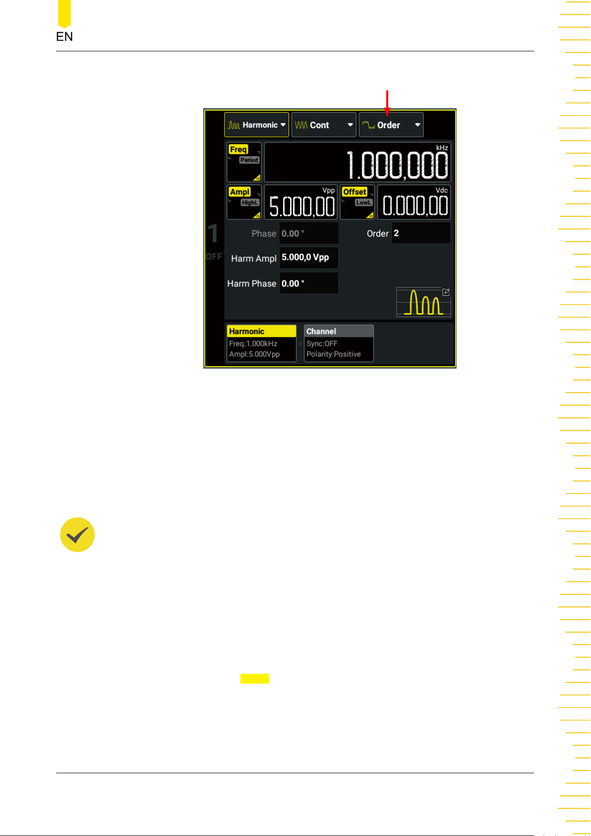
Harmonic Type
Continuous
Figure 5.2 Harmonic Setting Interface
Fundamental Waveform Parameters
DG800 Pro allows you to set the frequency/period, amplitude/high level, offset/low
level for fundamental waveforms. You can refer to
To Output Sine Wave
to set the
above parameters. Note that Vrms and dBm are not available for the unit of the
fundamental amplitude.
TIP
The max. fundamental frequency (
harmonic frequency (
the fundamental frequency. For the max. harmonic frequency (
to
Table 5.1 Range of Continuous Waveform Frequency
F
max
):
F
fund
F
) is limited by the harmonic order (N) and max.
fund
= (2 x
F
÷ N). Changing the harmonic order may modify
max
F
) of different models, refer
max
.
Harmonic Type
Click or tap the "Harmonic Type" drop-down button to select the desired type.
• Order: only outputs the basic waveform and the specified harmonic component.
For example, if the Order is set to 5, the instrument will output the basic
waveform and the 5th harmonic component.
• Combine: outputs harmonics with multiple harmonic components.
In this mode, 20 bits binary data are used to represent the output status of the
20 orders of harmonics respectively; wherein, 1 represents enabling the output
Copyright ©RIGOL TECHNOLOGIES CO., LTD. All rights reserved. DG800 Pro User Guide
51
Page 60
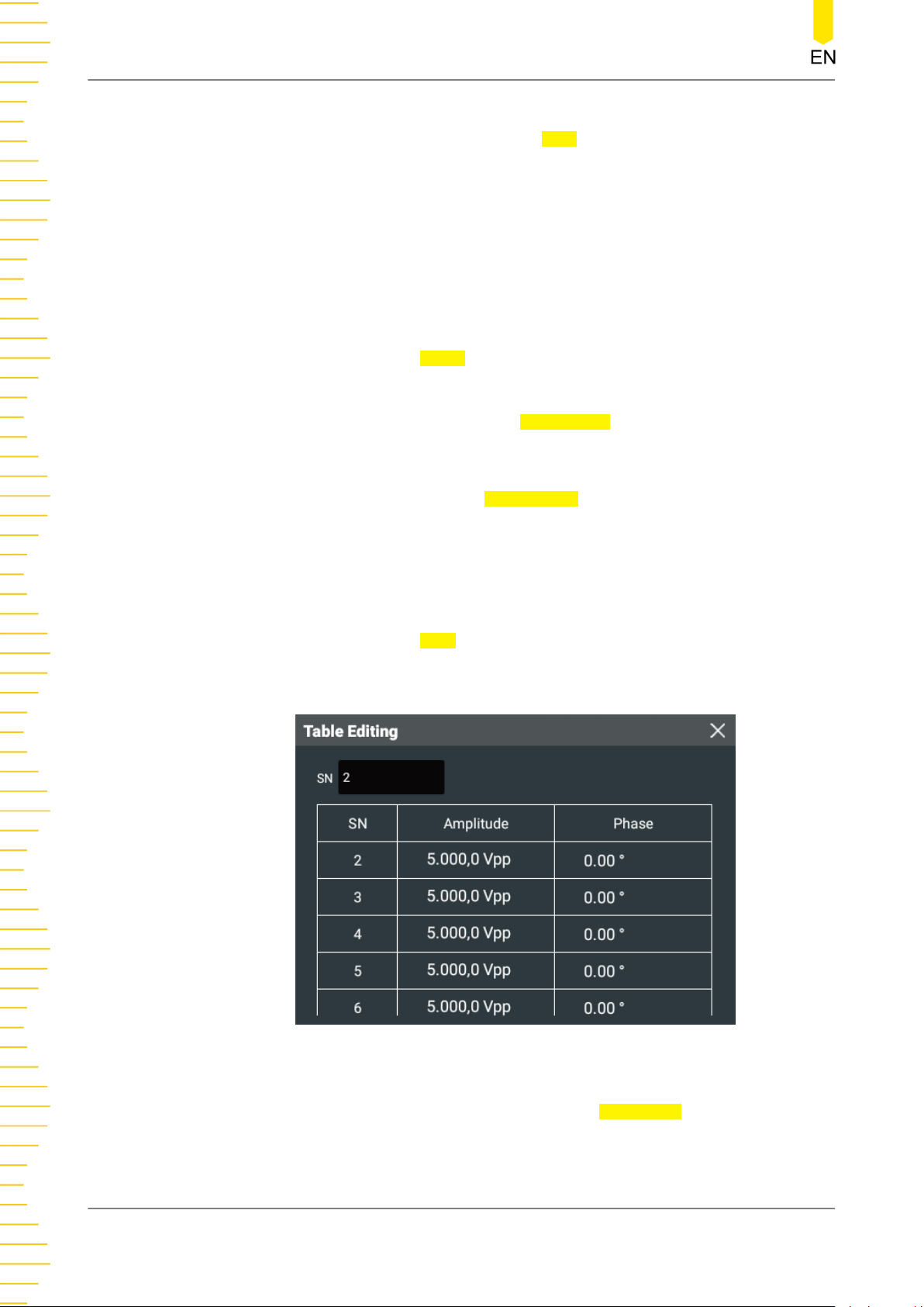
Continuous
of the corresponding harmonic and 0 represents disabling the output of the
corresponding harmonic. Click or tap the User input field and use the pop-up
virtual keypad to set the value of each data bit. Note that the leftmost bit
representing fundamental waveform is always X and can not be modified. For
example, set the 20 bits data to X001 0000 0000 0000 0001 and then
fundamental waveform as well as 4th and 20th orders of harmonics will be
output.
Order Harmonic
Click or tap the "Harmonic Type" drop-down button to select "Order" to enter the
setting menu. Click or tap the
Order input field to set the order. It ranges from 2
(default) to 20. After that, you can set the harmonic amplitude and phase.
• Harmonic Amplitude: click or tap the Harm Ampl input field to set the
amplitude with the pop-up virtual keypad.
• Harmonic Phase: click or tap the Harm Phase input field to set the phase with
the pop-up virtual keypad.
Combine Harmonic
Click or tap the "Harmonic Type" drop-down button to select "Combine" to enter the
setting menu. Click or tap the
User input field to set the user-defined orders of
harmonics. After that, you can click or tap the harmonic editing table to set the
amplitude and phase in the pop-up menu.
• Harmonic Amplitude: click or tap any cell in the Amplitude column and use the
DG800 Pro User Guide
52
Figure 5.3 Table Editing Menu
pop-up virtual keypad to set the amplitude for the harmonic with the specified
order.
Copyright ©RIGOL TECHNOLOGIES CO., LTD. All rights reserved.
Page 61

Continuous
• Harmonic Phase: click or tap any cell in the Phase column and use the pop-up
virtual keypad to set the phase for the harmonic with the specified order.
TIP
You can click or tap the SN input field to set the order to locate the specified harmonic quickly.
Channel Setup
You can also click or tap the "Channel" tab in
Continuous
interface to access the
channel setup interface to configure channel output. For details, please refer to
Channel Setup
.
Enable the Channel Output
Refer to
Enable the Channel Output
of the "To Output Sine Wave" section.
Copyright ©RIGOL TECHNOLOGIES CO., LTD. All rights reserved. DG800 Pro User Guide
53
Page 62
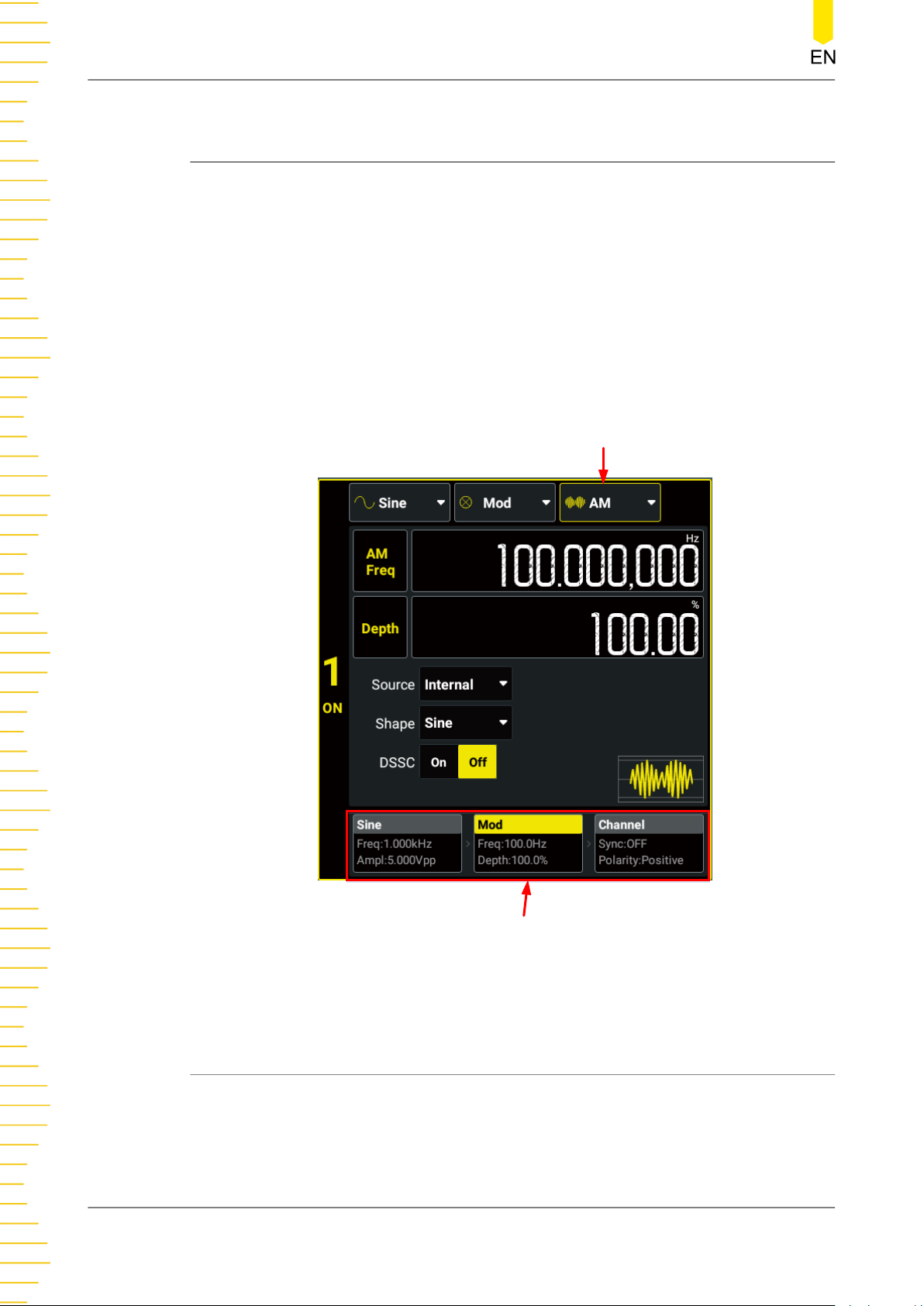
Modulation
6
Modulation
DG800 Pro allows you to output various modulated waveforms. Available modulation
types include AM, FM, PM, ASK, FSK, PSK, PWM, and SUM. Both internal and external
modulation sources are available for modulating waveforms.
Click or tap the "Output Mode" drop-down button to select "Mod" and access the
interface as shown in the figure below. You can click or tap one of the tabs at the
bottom to access the Continuous (Carrier) Setting Interface, Modulation Setting
Interface, or Channel Setup Interface. For Continuous (Carrier) Setting Interface and
Channel Setup Interface, please refer to
This chapter only describes the modulation settings.
Continuous
Modulation Type
and
Channel Setup
respectively.
Tabs
Figure 6.1 Modulation Setting Interface
6.1 Amplitude Modulation (AM)
In Amplitude Modulation (AM), a modulated waveform consists of a carrier waveform
and a modulating waveform. The amplitude of the carrier waveform is varied by the
instantaneous voltage of the modulating waveform. In the "Modulation Setting
DG800 Pro User Guide
54
Copyright ©RIGOL TECHNOLOGIES CO., LTD. All rights reserved.
Page 63

Modulation
Interface" (
Figure 6.1
), click or tap the "Modulation Type" drop-down button to select
"AM" and set its parameters.
Carrier Waveform
Available AM carrier waves include sine (default), square, ramp, and Arb (except DC).
Click or tap the "Wave Type" drop-down button or press the corresponding frontpanel waveform selection key to select the desired carrier waveform shape. Enter the
carrier setting interface and refer to
Continuous
to set the carrier parameters.
Modulating Waveform
The instrument accepts an internal or external signal as the modulation source. Click
or tap the Source drop-down button to select "Internal" or "External".
• Internal Source
After "Internal" is selected, you can click or tap the Shape drop-down button to
select the modulating waveform shape. Available shapes include:
- Sine
- Square with 50% duty cycle
- Triangle with 50% symmetry
- UpRamp with 100% symmetry
- DnRamp with 0% symmetry
- Noise - white gaussian noise
- Arb: When the "Shape" is set to Arb, you can click or tap the Shape input
field to set the Arb type.
• External Source
After "External" is selected,
Shape and AM Freq are grayed out and disabled.
The instrument accepts an external modulation source applied to the rear-panel
[AUX IN/OUT] connector. At this time, the amplitude of the modulated
waveform is controlled by the ±5 V signal level present on the connector.
NOTE
How to realize the intermodulation between dual channels? The following example takes the
output signal of CH2 as the modulating waveform.
1. Connect the CH2 output terminal to the rear-panel [AUX IN/OUT] connector of CH1 using
the dual BNC cable.
2. Select CH1 and set the output mode to "Mod". Select the desired modulation type and set
the corresponding parameters. Set the
3. Select CH2 and set the desired shape as well as the corresponding parameters.
4. Turn on the CH1 and CH2 outputs.
Copyright ©RIGOL TECHNOLOGIES CO., LTD. All rights reserved. DG800 Pro User Guide
Source to "External".
55
Page 64

Modulation
Modulation Frequency
After the internal modulation source is selected, click or tap the AM Freq input field
and set the modulation frequency with the pop-up numeric keypad. The available
range is from 2 mHz to 1 MHz, and the default is 100 Hz. The resolution is 1 μHz.
TIP
When an external modulation source is selected, this setting is grayed out and disabled.
Modulation Depth
Modulation depth is a percentage that represents the amplitude variation. Click or tap
the Depth input field to set the modulation depth. AM depth ranges from 0% to
120%. The default is 100%, and the resolution is 0.01%.
• At 0% depth, the amplitude is one-half of the carrier's amplitude setting.
• At 100% depth, the amplitude is identical to the carrier's amplitude setting.
• At greater than 100% depth, the output amplitude will not exceed the maximum
output amplitude .
When an external modulation source is selected, the AM modulation amplitude is
also controlled by the ±5 V signal level on the rear-panel [AUX IN/OUT] connector.
For example, if the modulation depth is set to 100%, then the output will be at the
maximum amplitude when the modulating signal is at +5 V. The output will be at the
minimum amplitude when the modulating signal is at -5 V.
DSSC
DG800 Pro supports two forms of amplitude modulation, Normal and Double
Sideband Suppressed Carrier (DSSC). In "normal" AM, the modulated wave consists of
the carrier wave and two sidebands. Such a modulation is inefficient because the
carrier wave carries no information. If this carrier is suppressed and the saved power
is distributed to the two sidebands, then such a process is called Double Sideband
Suppressed Carrier (DSSC).
By default, the "DSSC" is off. Click or tap the
DSSC on/off switch to turn on or off the
DSSC function.
6.2 Frequency Modulation (FM)
In Frequency Modulation (FM), a modulated waveform consists of a carrier waveform
and a modulating waveform. The frequency of the carrier waveform is varied by the
instantaneous voltage of the modulating waveform. In the "Modulation Setting
Interface" (
"FM" and set its parameters.
DG800 Pro User Guide
56
Figure 6.1
), click or tap the "Modulation Type" drop-down button to select
Copyright ©RIGOL TECHNOLOGIES CO., LTD. All rights reserved.
Page 65

Modulation
Carrier Waveform
Available FM carrier waves include sine (default), square, ramp, and Arb (except DC).
Click or tap the "Wave Type" drop-down button or press the corresponding frontpanel waveform selection key to select the desired carrier waveform shape. Enter the
carrier setting interface and refer to
Continuous
to set the carrier parameters.
Modulating Waveform
The instrument accepts an internal or external signal as the modulation source. Click
or tap the
Source drop-down button to select "Internal" or "External".
• Internal Source
After "Internal" is selected, you can click or tap the Shape drop-down button to
select the modulating waveform shape. Available shapes include:
- Sine
- Square with 50% duty cycle
- Triangle with 50% symmetry
- UpRamp with 100% symmetry
- DnRamp with 0% symmetry
- Noise - white gaussian noise
- Arb: When the "Shape" is set to Arb, you can click or tap the Shape input
field to set the Arb type.
• External Source
After "External" is selected,
Shape and FM Freq are grayed out and disabled. The
instrument accepts an external modulation source applied to the rear-panel
[AUX IN/OUT] connector. At this time, the amplitude of the modulated
waveform is controlled by the ±5 V signal level present on the connector.
Modulation Frequency
After the internal modulation source is selected, click or tap the
FM Freq input field
and set the modulation frequency with the pop-up numeric keypad. The available
range is from 2 mHz to 1 MHz, and the default is 100 Hz. The resolution is 1 μHz.
TIP
When an external modulation source is selected, this setting is grayed out and disabled.
Copyright ©RIGOL TECHNOLOGIES CO., LTD. All rights reserved. DG800 Pro User Guide
57
Page 66
Modulation
Frequency Deviation
It represents the peak variation in frequency of the modulated waveform from the
carrier frequency. Click or tap the Freq Dev input field to set the frequency deviation.
The minimum frequency deviation is 0 Hz.
• For FM, the frequency deviation must always be less than or equal to the carrier
frequency minus 1 μHz.
• The frequency deviation plus the carrier frequency must be less than or equal to
the selected carrier's maximum frequency.
When an external modulation source is selected, the frequency deviation is controlled
by the ±5 V signal level on the rear-panel [AUX IN/OUT] connector. For example, if
the frequency deviation is set to 1 kHz, the +5 V signal level corresponds to a 1 kHz
increase in frequency. Lower external signal levels produce less deviation and
negative signal levels reduce the frequency below the carrier frequency.
6.3 Phase Modulation (PM)
In Phase Modulation (PM), a modulated waveform consists of a carrier waveform and
a modulating waveform. The phase of the carrier waveform is varied by the
instantaneous voltage of the modulating waveform. In the "Modulation Setting
Interface" (
"PM" and set its parameters.
Carrier Waveform
Available PM carrier waves include sine (default), square, ramp, and Arb (except DC).
Click or tap the "Wave Type" drop-down button or press the corresponding frontpanel waveform selection key to select the desired carrier waveform shape and access
the setup interface. To configure different carrier waveforms, please refer to
Continuous
Modulating Waveform
The instrument accepts an internal or external signal as the modulation source. Click
or tap the Source drop-down button to select "Internal" or "External".
• Internal Source
Figure 6.1
.
), click or tap the "Modulation Type" drop-down button to select
DG800 Pro User Guide
58
After "Internal" is selected, you can click or tap the Shape drop-down button to
select the modulating waveform shape. Available shapes include:
- Sine
- Square with 50% duty cycle
- Triangle with 50% symmetry
- UpRamp with 100% symmetry
Copyright ©RIGOL TECHNOLOGIES CO., LTD. All rights reserved.
Page 67
- DnRamp with 0% symmetry
- Noise - white gaussian noise
- Arb: When the "Shape" is set to Arb, you can click or tap the Shape input
field to set the Arb type.
• External Source
Modulation
After "External" is selected,
The instrument accepts an external modulation source applied to the rear-panel
[AUX IN/OUT] connector. At this time, the amplitude of the modulated
waveform is controlled by the ±5 V signal level present on the connector.
Modulation Frequency
After the internal modulation source is selected, click or tap the PM Freq input field
and set the modulation frequency with the pop-up numeric keypad. The available
range is from 2 mHz to 1 MHz, and the default is 100 Hz. The resolution is 1 μHz.
TIP
When an external modulation source is selected, this setting is grayed out and disabled.
Phase Deviation
The phase deviation represents the peak variation in phase of the modulated
waveform from the carrier waveform. Click or tap the
phase deviation. It ranges from 0° to 360°, and the default is 90°. The resolution is
0.01°.
Shape and PM Freq are grayed out and disabled.
PM Dev input field to set the
When an external modulation source is selected, the phase deviation is controlled by
the ±5 V signal level on the rear-panel [AUX IN/OUT] connector. For example, if the
phase deviation is set to 180º, the +5 V signal level corresponds to a 180º phase shift.
Lower external signal levels produce less deviation.
6.4 Amplitude Shift Keying (ASK)
With Amplitude Shift Keying (ASK), you can configure the instrument to "shift" its
output amplitude between two preset values (called the "carrier amplitude" and
the"modulation amplitude"). In the "Modulation Setting Interface" (
or tap the "Modulation Type" drop-down button to select "ASK" and set its
parameters.
Carrier Waveform
Available ASK carrier waves include sine (default), square, ramp, and Arb (except DC).
Click or tap the "Wave Type" drop-down button or press the corresponding frontpanel waveform selection key to select the desired carrier waveform shape.
Figure 6.1
), click
Copyright ©RIGOL TECHNOLOGIES CO., LTD. All rights reserved. DG800 Pro User Guide
59
Page 68
Modulation
In the Carrier (Continuous) interface, click or tap the Ampl/HighL button to set the
parameter to "Ampl". Click or tap its input field and use the pop-up numeric keypad
to set the carrier amplitude. For carrier amplitude setting methods and available
range, please refer to
Continuous
.
Modulation Source
The instrument accepts an internal or external signal as the modulation source. Click
or tap the
Source drop-down button to select "Internal" or "External".
• Internal Source
When "Internal" is selected, the instrument uses a square wave with 50% duty
cycle as the ASK modulation source. At this time, the output amplitude "shifts"
between "carrier amplitude" and "modulation amplitude". The shift rate is
determined by "ASK Rate".
• External Source
When "External" is selected, the generator receives the external modulating
signal from the rear-panel [AUX IN/OUT] connector.
ASK Rate
ASK rate is the rate at which the output amplitude "shifts" between the carrier
amplitude and modulation amplitude when an internal modulation source is used.
Click or tap the
ASK Rate input field and use the pop-up numeric keypad to set the
rate. The available range is from 2 mHz to 1 MHz, and the default is 100 Hz. The
resolution is 1 μHz.
TIP
When the external modulation source is selected, this setting is grayed out and disabled.
Modulation Amplitude
Click or tap the ASK Ampl input field and use the pop-up numeric keypad to set the
modulation amplitude. The available range of modulation amplitude is consistent
with the range of basic waveform amplitude and the default is 2 Vpp.
Polarity
Click or tap the
control the amplitude output. The default is "Positive".
• Positive: when the internal/external modulation signal is a logic low level, the
• Negative: when the internal/external modulation signal is a logic low level, the
DG800 Pro User Guide
60
Polarity drop-down button to select "Positive" or "Negative" to
carrier amplitude is output; when the signal is a logic high level, the modulation
amplitude is output.
modulation amplitude is output; when the signal is a logic high level, the carrier
amplitude is output.
Copyright ©RIGOL TECHNOLOGIES CO., LTD. All rights reserved.
Page 69

6.5 Frequency Shift Keying (FSK)
With Frequency Shift Keying (FSK), you can configure the instrument to "shift" its
output frequency between two preset values (called the "carrier frequency" and
the"hop frequency”). In the "Modulation Setting Interface" (
the "Modulation Type" drop-down button to select "FSK" and set its parameters.
Carrier Waveform
Available FSK carrier waves include sine (default), square, ramp, and Arb (except DC).
Click or tap the "Wave Type" drop-down button or press the corresponding frontpanel waveform selection key to select the desired carrier waveform shape.
Figure 6.1
Modulation
), click or tap
In the Carrier (Continuous) interface, click or tap the
parameter to "Freq". Click or tap its input field and use the pop-up numeric keypad to
set the carrier frequency. The frequency range varies for different carrier waveforms.
For details, refer to
Modulation Source
The instrument accepts an internal or external signal as the modulation source. Click
or tap the
• Internal Source
• External Source
FSK Rate
Source drop-down button to select "Internal" or "External".
When "Internal" is selected, the instrument uses a square wave with 50% duty
cycle as the FSK modulation source. At this time, the output frequency "shifts"
between "carrier frequency" and "hop frequency". The shift rate is determined by
“FSK Rate”.
When "External" is selected, the generator receives the external modulating
signal from the rear-panel [AUX IN/OUT] connector.
Continuous
.
Freq/Period button to set the
FSK rate is the rate at which the output frequency "shifts" between the carrier
frequency and the hop frequency when an internal modulation source is used. Click
or tap the
The available range is from 2 mHz to 1 MHz, and the default is 100 Hz.
TIP
When the external modulation source is selected, this setting is grayed out and disabled.
Hop Frequency
Click or tap the Hop Freq input field and use the pop-up numeric keypad to set the
hop frequency. The range of hop frequency is related to the instrument model and
wave type. For details, refer to
Copyright ©RIGOL TECHNOLOGIES CO., LTD. All rights reserved. DG800 Pro User Guide
FSK Rate input field and use the pop-up numeric keypad to set the rate.
Table 5.1 Range of Continuous Waveform Frequency
.
61
Page 70

Modulation
Polarity
Click or tap the Polarity drop-down button to select "Positive" or "Negative" to
control the frequency output. The default is "Positive".
• Positive: when the internal/external modulation signal is a logic low level, the
carrier frequency is output; when the signal is a logic high level, the hop
frequency is output.
• Negative: when the internal/external modulation signal is a logic low level, the
hop frequency is output; when the signal is a logic high level, the carrier
frequency is output.
6.6 Phase Shift Keying (PSK)
In Phase Shift Keying (PSK), you can configure the instrument to "shift" its output
phase between two preset phase settings ("carrier phase" and "modulation phase"). In
the "Modulation Setting Interface" (
drop-down button to select "PSK" and set its parameters.
Figure 6.1
), click or tap the "Modulation Type"
Carrier Waveform
Available PSK carrier waves include sine (default), square, ramp, and Arb (except DC).
Click or tap the "Wave Type" drop-down button or press the corresponding frontpanel waveform selection key to select the desired carrier waveform shape.
In the Carrier (Continuous) interface, click or tap the "Phase" input field and use the
pop-up numeric keypad to set the starting phase. It ranges from -360° to 360°, and
the default is 0°. The resolution is 0.01°.
Modulation Source
The instrument accepts an internal or external signal as the modulation source. Click
or tap the
• Internal Source
• External Source
Source drop-down button to select "Internal" or "External".
When "Internal" is selected, the instrument uses a square wave with 50% duty
cycle as the PSK modulation source. At this time, the output phase "shifts"
between "carrier phase" and "modulation phase". The shift rate is determined by
"PSK Rate".
PSK Rate
PSK rate is the rate at which the output phase "shifts" between the carrier phase and
modulation phase when an internal modulation source is used. Click or tap the
DG800 Pro User Guide
62
When "External" is selected, the generator receives the external modulating
signal from the rear-panel [AUX IN/OUT] connector.
PSK
Copyright ©RIGOL TECHNOLOGIES CO., LTD. All rights reserved.
Page 71
Modulation
Rate input field and use the pop-up numeric keypad to set the rate. The available
range is from 2 mHz to 1 MHz, and the default is 100 Hz. The resolution is 1 μHz.
TIP
When the external modulation source is selected, this setting is grayed out and disabled.
Modulation Phase
Click or tap the Phase input field and use the pop-up numeric keypad to set the
modulation phase. It ranges from 0° to 360°, and the default is 180°. The resolution is
0.01°.
Polarity
Click or tap the Polarity drop-down button to select "Positive" or "Negative" to
control the phase output. The default is "Positive".
• Positive: when the internal/external modulation signal is a logic low level, the
carrier phase is output; when the signal is a logic high level, the modulation
phase is output.
• Negative: when the internal/external modulation signal is a logic low level, the
modulation phase is output; when the signal is a logic high level, the carrier
phase is output.
6.7 Pulse Width Modulation (PWM)
For Pulse Width Modulation (PWM), the pulse width of the output signal is varied by
the instantaneous voltage of the modulating waveform. The amount by which the
pulse width varies is called the width deviation.
TIP
To select the PWM function, first click or tap the "Wave Type" drop-down button to select
"Pulse" and then set the "Output Mode" to "Mod". The modulation type will be set to "PWM"
automatically. Refer to the following section to set the other modulation parameters.
Carrier Waveform
PWM is only available for the Pulse waveform. Click or tap the "Wave Type" drop-
down button to select "Pulse" or press the front-panel key to set the carrier
waveform to Pulse.
For pulse width/duty cycle setting, refer to
To Output Pulse
.
Modulation Source
The instrument accepts an internal or external signal as the modulation source. Click
or tap the Source drop-down button to select "Internal" or "External".
Copyright ©RIGOL TECHNOLOGIES CO., LTD. All rights reserved. DG800 Pro User Guide
63
Page 72
Modulation
• Internal Source
After "Internal" is selected, you can click or tap the Shape drop-down button to
select the modulating waveform shape. Available shapes include:
- Sine
- Square with 50% duty cycle
- Triangle with 50% symmetry
- UpRamp with 100% symmetry
- DnRamp with 0% symmetry
- Noise - white gaussian noise
- Arb: When the "Shape" is set to Arb, you can click or tap the Shape input
field to set the Arb type.
External Source
•
After "External" is selected,
Shape and PWM Freq are grayed out and disabled.
The instrument accepts an external modulation source applied to the rear-panel
[AUX IN/OUT] connector. At this time, the amplitude of the modulated
waveform is controlled by the ±5 V signal level present on the connector.
Modulation Frequency
After the internal modulation source is selected, click or tap the
PWM Freq input field
and set the modulation frequency with the pop-up numeric keypad. The available
range is from 2 mHz to 1 MHz, and the default is 100 Hz.
TIP
When an external modulation source is selected, this setting is disabled.
Width Deviation/Duty Cycle Deviation
PWM deviation represents the variation of the modulated waveform pulse width
relative to the original pulse width. You can use time (width deviation) or duty cycle
(duty cycle deviation) to set the PWM deviation. This setting is subject to the
Width/Duty Cycle
for
Pulse Width/Duty Cycle
setting in Carrier (Pulse) setting. For example, if "Width" is selected
of the Pulse setting, then the PWM deviation setting is
Pulse
automatically set to "Width Dev".
• Width Deviation
DG800 Pro User Guide
64
Width deviation represents the amount by which the pulse width of the
modulated waveform varies from the original pulse width. The unit is s. For
example, if you specify a pulse width as 10 s and width deviation as 5 s, the
Copyright ©RIGOL TECHNOLOGIES CO., LTD. All rights reserved.
Page 73

Modulation
pulse width of the modulated waveform varies from 5 s to 15 s under the control
of the modulating signal.
Click or tap the Duty Dev/Width Dev button to set the parameter to "Width
Dev". "Width Dev" is now highlighted. Click or tap its input field to set the width
deviation. The range of the width deviation is limited by the pulse width, pulse
period, and leading/trailing edge of the pulse waveform:
- Width Deviation ≤ Pulse Width - 5.25 ns -(Leading Edge Time + Trailing
Edge Time)/1.6.
- Width Deviation ≤ Pulse Period - Pulse Width - 5.25 ns-(Leading Edge Time
+ Trailing Edge Time)/1.6.
• Duty Cycle Deviation
Duty cycle deviation represents the amount by which the pulse width of the
modulated waveform varies from the original pulse width. The unit is the
percentage of the waveform period. For example, if you specify a pulse duty
cycle as 10% and duty cycle deviation as 5%, the duty cycle of the modulated
waveform varies from 5% to 15% under the control of the modulating signal.
Click or tap the
Dev". "Duty Dev" is now highlighted. Click or tap its input field to set the duty
cycle deviation. The duty cycle deviation ranges from 0% to 49.99%, and is
limited by the period, duty cycle, and edge time of the pulse waveform.
When an external modulation source is selected, the width deviation (or duty cycle
deviation) is controlled by the ±5 V signal level on the rear-panel [AUX IN/OUT]
connector. For example, if the width deviation is set to 10 s, the +5 V signal level
corresponds to a 10 s deviation.
Duty Dev/Width Dev button to set the parameter to "Duty
6.8 SUM Modulation
When the waveform summing function is enabled, you can add a specified waveform
to the current basic/Arb waveform. In the "Modulation Setting Interface" (
click or tap the "Modulation Type" drop-down button to select "SUM" and set its
parameters.
Carrier Waveform
Available carrier waves include sine (default), square, ramp, and Arb (except DC). Click
or tap the "Wave Type" drop-down button or press the corresponding front-panel
waveform selection key to select the desired carrier waveform shape. Enter the carrier
setting interface and refer to
Continuous
to set the carrier parameters.
Figure 6.1
),
Sum Source
Click or tap the
the current waveform. Available waveform shapes include:
Copyright ©RIGOL TECHNOLOGIES CO., LTD. All rights reserved. DG800 Pro User Guide
Waveform drop-down button to select the waveform to be added to
65
Page 74

Modulation
• Sine
• Square with 50% duty cycle
• Triangle with 50% symmetry
• UpRamp with 100% symmetry
• DnRamp with 0% symmetry
• Noise - white gaussian noise
• Arb: When the "Shape" is set to Arb, you can click or tap the Waveform input
field to set the Arb type.
Sum Frequency
It sets the frequency of the waveform to be added to the current continuous
waveform. Click or tap the SUM Freq input field and use the pop-up virtual keypad to
set the frequency. The range of the Sum frequency is from 2 mHz to 1 MHz.
Sum Ratio
It sets the ratio of the amplitude of the waveform to be added relative to the
amplitude of the current waveform. Click or tap the
SUM Ratio input field and use
the pop-up virtual keypad to set the ratio. The default value is 50%. The available
range is limited by the current carrier amplitude and max. amplitude.
DG800 Pro User Guide
66
Copyright ©RIGOL TECHNOLOGIES CO., LTD. All rights reserved.
Page 75
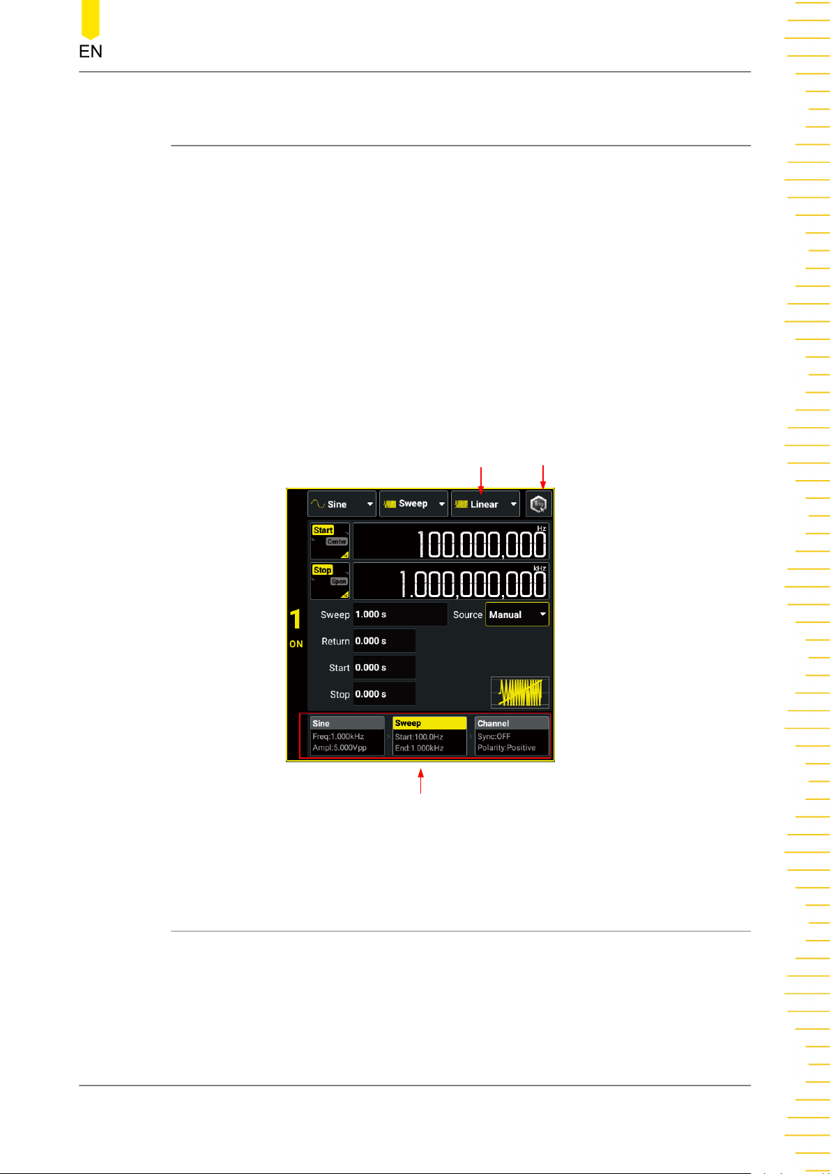
Sweep
7
Sweep
In frequency sweep mode, the instrument moves from the start frequency to the stop
frequency within a specified sweep time. You can sweep up or down in frequency,
with linear, logarithmic, or step sweep types. It allows you to set the "Mark"
frequency, start/stop hold time, and return time. It provides trigger sources including
internal, external, and manual sources. You can sweep sine, square, ramp, and Arb
(except DC).
Click or tap the "Output Mode" drop-down button to select "Sweep" and access the
interface as shown in the figure below. You can click or tap one of the tabs at the
bottom to access the Continuous Setting Interface, Sweep Setting Interface, or
Channel Setup Interface. For Continuous Setting Interface and Channel Setup
Interface, please refer to
only describes the sweep settings.
Continuous
and
Channel Setup
Sweep Type
respectively. This chapter
Manual Trigger Key
Tabs
Figure 7.1 Sweep Setting Interface
7.1 Sweep Type
This instrument provides three sweep types: Linear, Log, and Step. The default is
Linear. Click or tap the "Sweep Type" drop-down button to select "Linear", "Log", or
"Step".
Copyright ©RIGOL TECHNOLOGIES CO., LTD. All rights reserved. DG800 Pro User Guide
67
Page 76
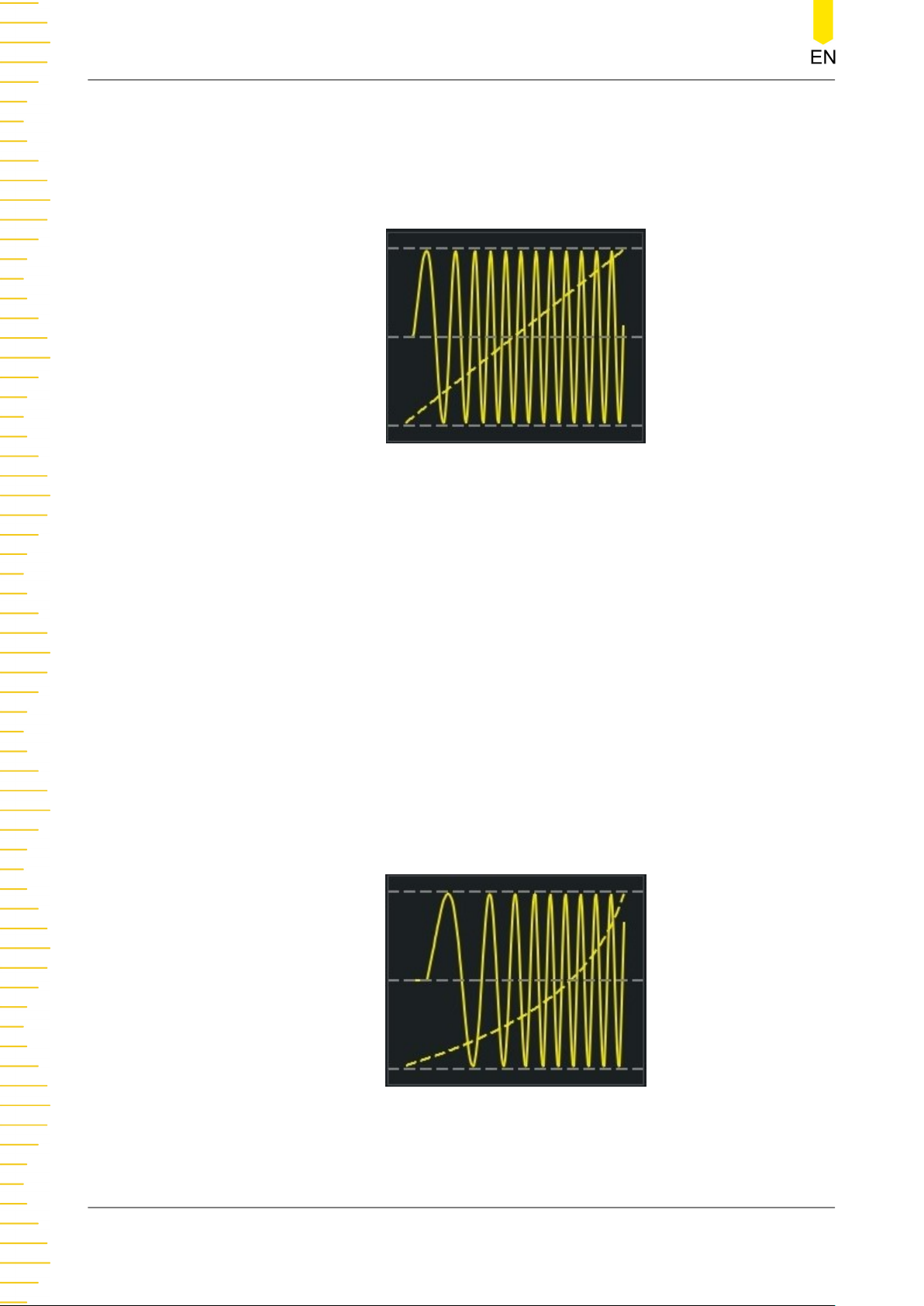
Sweep
Linear Sweep
The instrument varies the output frequency linearly during the sweep, changing the
output frequency by a constant number of Hz per second. It is characterized by "Start
Frequency", "Stop Frequency", and "Sweep Time".
Figure 7.2 Linear Sweep
Logarithmic Sweep
The instrument varies the output frequency logarithmically during the sweep,
changing the frequency by a constant number of octaves. It is characterized by "Start
Frequency", "Stop Frequency", and "Sweep Time".
F
,
F
, and
T
Define the start frequency, stop frequency, sweep time as
function of logarithmic sweep is F =
T
P
; wherein, P and T can be expressed in the
start
stop
sweep
. The
following equations:
P = 10
T
= t + lg(F
lg(F
stop/Fstart
start
)/T
sweep
)/lg(P)
In the equations above, t is the duration time after the sweep starts, ranging from 0
to
T
; F is the current instantaneous frequency.
sweep
DG800 Pro User Guide
68
Figure 7.3 Logarithmic Sweep
Copyright ©RIGOL TECHNOLOGIES CO., LTD. All rights reserved.
Page 77
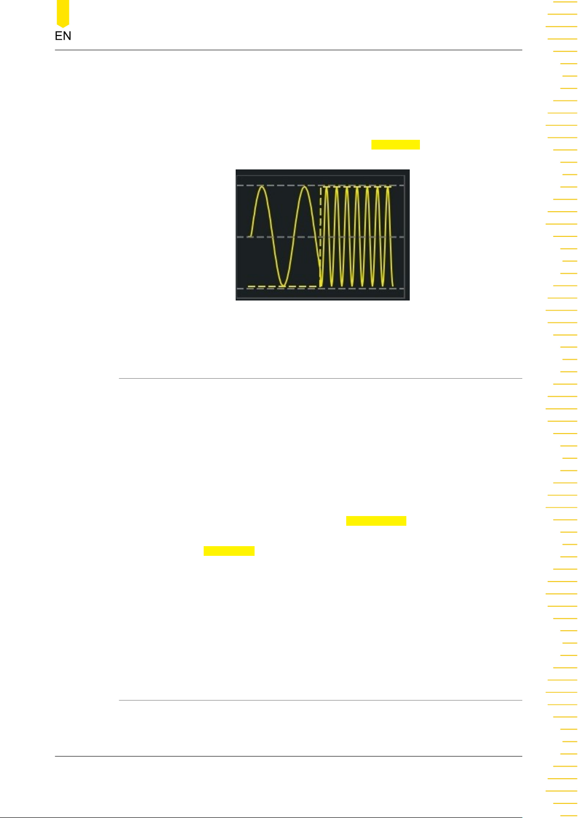
Sweep
Step Sweep
The instrument "steps" through a list of frequencies during the sweep. The period that
the output signal dwells on each frequency is determined by "Sweep Time" and "Step
Number".
When the sweep type is set to "Step", click or tap the
number of steps. It ranges from 2 (default) to 1024.
Figure 7.4 Step Sweep
Step Num input field to set the
7.2 Start Frequency and Stop Frequency
The start frequency and stop frequency set the sweep's upper and lower frequency
bounds. The sweep begins at the start frequency, sweeps to the stop frequency, and
then resets back to the start frequency.
• To sweep up in frequency, set the start frequency less than the stop frequency.
• To sweep down in frequency, set the opposite relationship.
• To sweep in a fixed frequency, set the same start frequency and stop frequency.
After enabling the sweep mode, click or tap the Start/Center button to set the
parameter to "Start". "Start" is now highlighted. This operation also toggles the
parameter of the Stop/Span button to "Stop". Click or tap the corresponding input
field and use the pop-up numeric keypad to set the start frequency and stop
frequency. By default, the start frequency is 100 Hz and the stop frequency is 1 kHz.
The range of start/stop frequency is related to the instrument model and wave type.
For details, refer to
After the start/stop frequency is modified, the instrument will sweep from the
specified start frequency again.
Table 5.1 Range of Continuous Waveform Frequency
7.3 Center Frequency and Frequency Span
You can also set the sweep frequency boundaries of the sweep using a center
frequency and frequency span.
.
Copyright ©RIGOL TECHNOLOGIES CO., LTD. All rights reserved. DG800 Pro User Guide
69
Page 78
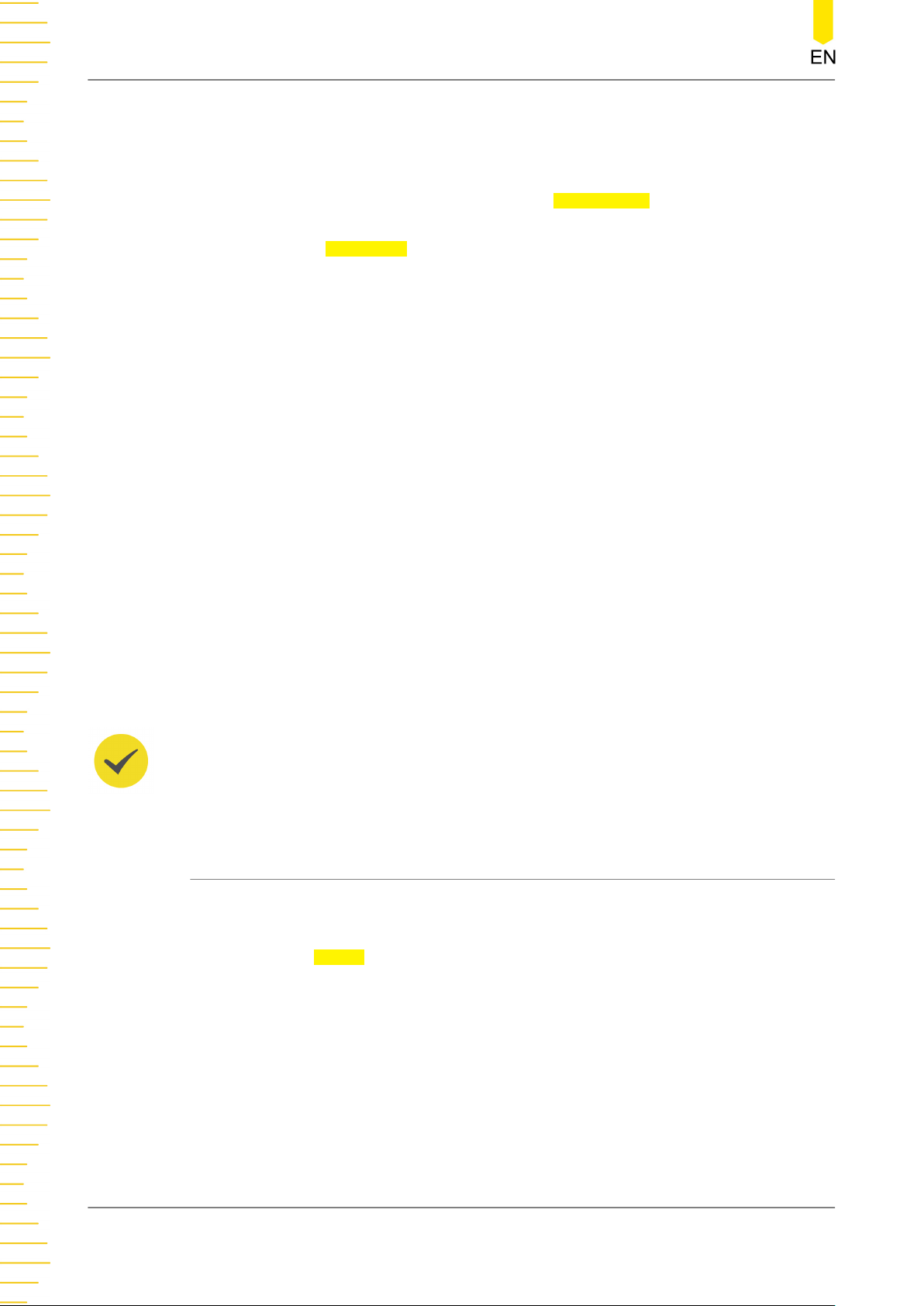
Sweep
• Center Frequency = (Start Frequency + Stop Frequency)/2
• Frequency Span = Stop Frequency - Start Frequency
After enabling the sweep mode, click or tap the Start/Center button to set the
parameter to "Center". "Center" is now highlighted. This operation also toggles the
parameter of the
Stop/Span button to "Span". Click or tap the corresponding input
field and use the pop-up numeric keypad to set the center frequency or frequency
span. By default, the center frequency is 550 Hz and the frequency span is 900 Hz. The
ranges of center frequency and frequency span vary for different waveforms. Also,
they are limited to each other.
The range of frequency span is affected by the center frequency. Define the upper
F
limit of the start/stop frequency as
frequency as
F
)/2.
min
F
(
Table 5.1 Range of Continuous Waveform Frequency
min
and the lower limit of the start/stop
max
).
F
= (
F
max
-
m
• When Center Frequency ≤
F
).
min
• When Center Frequency >
Frequency).
Take sine wave as an example.
center frequency is 5 MHz, the frequency span range is ±2 x (5 MHz - 1 μHz) = ±10
MHz; if the center frequency is 30 MHz, the frequency span range is ±2 x (50 MHz 30 MHz) = ±40 MHz.
TIP
To sweep up in frequency, set a positive frequency span; to sweep down, set a negative
frequency span.
7.4 Sweep Time
Sweep time specifies the time required to sweep from the start frequency to the stop
frequency.
F
, the Frequency Span is ±2 x (Center Frequency -
m
F
, the Frequency Span is ±2 x (
m
F
is 1 μHz,
min
F
is 50 MHz, and
max
F
- Center
max
F
is 25 MHz. If the
m
Click or tap the Sweep input field and use the pop-up numeric keypad to set the
sweep time. The default sweep time is 1 s and the resolution is 1 ms. The sweep time
ranges from 1 ms to 250,000 s. The sweep time is related to the sweep type, trigger
source, start hold time, return time, and stop hold time.
Time + Return Time + Stop Hold Time:
• Linear Sweep:
DG800 Pro User Guide
70
T
- Internal trigger:
+ 1 ms ≤ 8,000 s
P
- Manual trigger/external trigger:
Copyright ©RIGOL TECHNOLOGIES CO., LTD. All rights reserved.
T
≤ 250,000 s
P
T
= Sweep Time + Start Hold
P
Page 79
Sweep
• Log Sweep/Step Sweep:
T
≤ 500 s
P
After the sweep time is modified, the instrument will sweep from the specified "Start
Frequency" again.
7.5 Start/Stop Hold Time
Start hold time specifies the time for the sweep to remain at the "Start Frequency".
After the start hold time expires, the generator continues to sweep at varied
frequencies according to the current sweep type.
Stop hold time specifies the time for the sweep to remain at the "Stop Frequency"
after the generator sweeps from the "Start Frequency" to the "Stop Frequency".
You can click or tap the
set the start/stop hold time. The default start/stop hold time is 0 s and the resolution
is 1 ms. The time ranges from 0 s to 3600 s and is related to the sweep type, trigger
source, return time, and sweep time.
Time + Stop Hold Time:
• Linear Sweep:
Start/Stop input field and use the pop-up numeric keypad to
T
= Sweep Time + Start Hold Time + Return
P
- Internal trigger:
- Manual trigger/external trigger:
• Log Sweep/Step Sweep:
After the start/stop hold time is modified, the instrument will sweep from the
specified start frequency again.
7.6 Return Time
Return time specifies the time to return from the "Stop Frequency" to the "Start
Frequency".
Click or tap the Return input field and use the pop-up numeric keypad to set the
return time. The default return time is 0 s and the resolution is 1 ms. The time ranges
from 0 s to 3600 s and is related to the sweep type, trigger source, start hold time,
stop hold time, and sweep time.
Stop Hold Time:
• Linear Sweep:
T
+ 1 ms ≤ 8,000 s
P
T
≤ 500 s
P
T
= Sweep Time + Start Hold Time + Return Time +
P
T
≤ 250,000 s
P
T
- Internal trigger:
- Manual trigger/external trigger:
• Log Sweep/Step Sweep:
Copyright ©RIGOL TECHNOLOGIES CO., LTD. All rights reserved. DG800 Pro User Guide
+ 1 ms ≤ 8,000 s
P
T
≤ 500 s
P
T
≤ 250,000 s
P
71
Page 80
Sweep
After the return time is modified, the instrument will sweep from the specified "Start
Frequency" again.
7.7 Sweep Trigger Source
The sweep trigger source can be internal trigger, external leading edge, external
trailing edge, or manual trigger. The instrument outputs a single sweep when a
trigger signal is received and waits for the next trigger. Click or tap the Source dropdown button and select the trigger source. The default is "Internal".
• Internal: The instrument outputs a continuous sweep. The trigger period is
determined by the specified sweep time, return time, start hold time, and stop
hold time.
• Ext Leading: The instrument receives the trigger signal from the rear-panel [AUX
IN/OUT] connector. A sweep is generated each time a TTL pulse with leading
edge is received.
• Ext Trailing: The instrument receives the trigger signal from the rear-panel [AUX
IN/OUT] connector. A sweep is generated each time a TTL pulse with trailing
edge is received.
• Manual: When "Manual" is selected, click or tap the manual trigger key
press the front-panel key to initiate a sweep output immediately.
TIP
When "Internal" or "Manual" is selected, the generator outputs a TTL-compatible signal with
the specified edge via the rear-panel [AUX IN/OUT] connector. Please refer to
Setup
.
7.8 Mark Frequency
For frequency sweeps, the sync signal outputs a high level at the beginning of the
sweep. If you disable the "Mark" function, the sync signal goes low at the end of the
sweep. If you enable the "Mark" function, the sync signal goes low at the specified
marker frequency.
or
Trigger Output
After enabling the Sweep function, click or tap the Channel tab at the bottom to enter
the Channel Setup Interface. Click or tap the
the function. When it is enabled, you can click or tap the Mark Freq input field to set
the mark frequency. Mark frequency is limited by the sweep "Start Frequency" and
"Stop Frequency".
NOTE
For step sweep (the sweep points determined by the start frequency, stop frequency, and step
number respectively are f1, f2,……, fn, fn+1……), if the mark frequency setting is one of the
DG800 Pro User Guide
72
Mark on/off switch to enable or disable
Copyright ©RIGOL TECHNOLOGIES CO., LTD. All rights reserved.
Page 81

Sweep
sweep point values, the sync signal is a TTL high level at the beginning of the sweep and a low
level at the mark frequency. If the mark frequency is not equal to any of the sweep points
values, the sync signal becomes a low level at the sweep point which is closest to this mark
frequency (sweep up/down). Take sweeping down as an example. If the mark frequency is set
to 1 MHz and the sweep points are 0.99 MHz and 1.01 MHz, then 0.99 MHz will be selected as
the mark frequency to be applied to the digital system.
Copyright ©RIGOL TECHNOLOGIES CO., LTD. All rights reserved. DG800 Pro User Guide
73
Page 82
Burst
8
Burst
DG800 Pro can output a waveform for a specified number of cycles, called a burst.
You can use Sine, Square, Ramp, Pulse, Arb (except DC), and Noise (only available for
"Gated" Burst) to generate burst waveforms.
Click or tap the "Output Mode" drop-down button to select "Burst" to enter the Burst
Setting Interface, as shown in the figure below. You can click or tap one of the tabs at
the bottom to enter the Continuous Setting Interface, Burst Setting Interface, or
Channel Setup Interface. For Continuous Setting Interface and Channel Setup
Interface, please refer to
only describes the burst settings.
TIP
The Burst mode cannot be enabled when the fundamental frequency is less than or equal to
125 μHz.
Continuous
and
Channel Setup
respectively. This chapter
Burst Type
DG800 Pro User Guide
74
Tabs
Figure 8.1 Burst Setting Interface
Copyright ©RIGOL TECHNOLOGIES CO., LTD. All rights reserved.
Page 83
8.1 Burst Type
DG800 Pro can output two types of bursts: N-Cycle Burst (default) and Gated Burst. In
the Burst Setting Interface (
button to select "NCycle" or "Gated". The table below illustrates the trigger sources
and waveform parameters available for the two burst types.
Burst Type Trigger Source Burst Parameters
Figure 8.1
Burst
), click or tap the "Burst Type" drop-down
Userdefined
N-Cycle
Burst
Infinite
Gated Burst External Trigger Starting Phase, Polarity, Idle Level
N-Cycle Burst
In N-Cycle Burst mode, the instrument outputs a waveform for a specified number of
cycles (burst count) each time trigger is received. You can also set the burst count to
"Infinite". Available waveform functions for N-Cycle burst include Sine, Square, Ramp,
Pulse, and Arb (except DC). Click or tap the
count.
• Infinite: Infinite Burst sets the burst count to "infinite". The instrument outputs a
continuous waveform when a trigger signal is received.
Internal/External/
Manual Trigger
External/Manual
Trigger
Delay, Burst Period, Source, Trigger Output
(only available for manual trigger and
internal trigger), Phase, Cycles, Idle Level
Delay, Source, Trigger Output (only
available for manual trigger), Phase,
Cycles, Idle Level
Cycles drop-down button to set the burst
• User: Click or tap the
set the burst count. It ranges from 1 (default) to 1 M. If you change the burst
count, the instrument automatically increases the burst period to accommodate
the burst count (but the waveform frequency will not be changed).
Gated Burst
In Gated Burst mode, the generator controls the waveform output based on the
external signal level from the rear-panel [AUX IN/OUT] connector. Available
waveform functions for Gated burst include Sine, Square, Ramp, Pulse, Noise, and Arb
(except DC). When the gate signal is "true", the instrument outputs a continuous
waveform. When the gate signal is "false", the instrument first stops the current
waveform output and remains at the voltage level corresponding to the "Idle Level"
setting.
Copyright ©RIGOL TECHNOLOGIES CO., LTD. All rights reserved. DG800 Pro User Guide
Cycles input field and use the pop-up numeric keypad to
75
Page 84
Burst
8.2 Burst Delay
Burst delay, which is only available for N-Cycle Burst mode, is the duration from the
time when the instrument receives the trigger signal to the time when it starts to
output the burst signal.
Click or tap the Delay input field and use the pop-up numeric keypad to set the delay.
The default delay is 0 s and the resolution is 0.1 ns. The range of burst delay is related
to the trigger source:
• Manual/external trigger: 0 s to 20 s.
• Internal trigger: 0 s to (
than or equal to 20 s.
-
T
: burst period
burst
-
T
: period of basic waveform (e.g. Sine and Square)
wave
-
N
: burst count
cycle
NOTE
[1]: ⌈x⌉ indicates that x is rounded up.
8.3 Burst Phase
In Burst mode, the phase of the basic waveform is no longer in effect. The phase
characteristics are determined by the burst phase. When the burst type is set to
"NCycle", click or tap the Phase input field to set the burst phase. When the burst
type is set to "Gated", click or tap the Start Phase input field to set the phase. It
ranges from -360° to 360°, and the default is 0°. The resolution is 0.01°.
T
burst
- ⌈
T
wave
x N
÷ 6.4 ns⌉ x 6.4 ns - 4 μs)
cycle
[1]
, and less
• For Sine, Square, Pulse, and Ramp, 0° is the point at which the waveform crosses
• Burst phase setting is not available for noise.
• For arbitrary waveforms, 0° is the first waveform point.
TIP
In Burst mode, the phase of the basic waveform is fixed to 0° and cannot be modified.
DG800 Pro User Guide
76
0 V (or DC offset) in a positive-going direction.
Copyright ©RIGOL TECHNOLOGIES CO., LTD. All rights reserved.
Page 85
8.4 Burst Period
Burst period is only available for internally triggered N-Cycle burst mode (userdefined burst count). Burst period is defined as the time from the start of a burst to
the time when the next burst starts.
Click or tap the Burst Period input field and use the pop-up numeric keypad to set
the period. It ranges from 4 μs to 8 ks and the default is 10 ms. The resolution is 0.1
ns.
Burst
• Burst Period ≥ ⌈(Burst Count x Waveform Period) ÷ 6.4 ns⌉ x 6.4 ns + 4 μs
• If the burst period is too short, the generator will increase it automatically to
allow the output of the specified number of cycles.
NOTE
[1]: ⌈x⌉ indicates that x is rounded up.
8.5 Burst Trigger Source
Available trigger sources for bursts include internal trigger, external leading edge,
external trailing edge, and manual trigger. Click or tap the Source drop-down button
and select the trigger source. The default is "Internal".
• Internal: Internal trigger is only available for N-Cycle Burst with user-defined
burst count. When internal trigger is selected, the instrument outputs a burst of
the specified cycles. The rate at which the burst is generated is determined by
Burst Period
outputs the idle level and waits for the next trigger event.
. After completing the specified number of cycles, the instrument
[1]
• Ext Leading: When external leading edge is selected, the instrument receives the
trigger signal from the rear-panel [AUX IN/OUT] connector. A burst is generated
each time a TTL pulse with leading edge is received.
• Ext Trailing: When external trailing edge is selected, the instrument receives the
trigger signal from the rear-panel [AUX IN/OUT] connector. A burst is generated
each time a TTL pulse with trailing edge is received.
• Manual: Manual trigger is only available for N-Cycle Burst mode. When manual
in
trigger is selected, click or tap the manual trigger key
or press the front-panel
output of the corresponding channel is not enabled, the trigger will be ignored.
Copyright ©RIGOL TECHNOLOGIES CO., LTD. All rights reserved. DG800 Pro User Guide
key to initiate a burst output immediately. If the
Figure 8.1
interface
77
Page 86
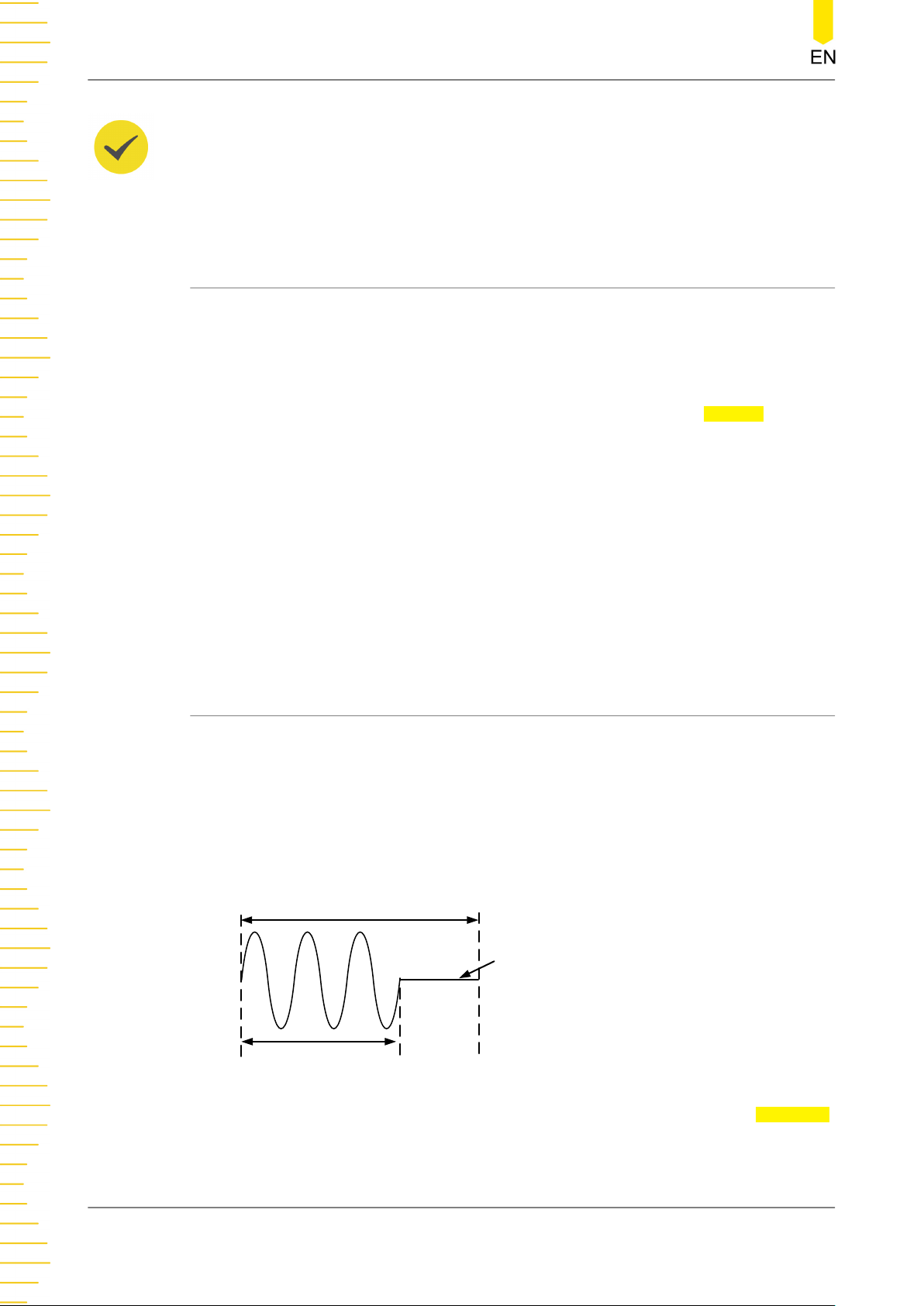
Burst
TIP
When "Internal" or "Manual" is selected, the generator outputs a TTL-compatible signal with
the specified edge via the rear-panel [AUX IN/OUT] connector. Please refer to
Setup
.
8.6 Gated Polarity
Gated polarity is only available for Gated Burst mode. It enables the instrument to
output burst signals at a high level or low level. The gate signal is applied to the rearpanel [AUX IN/OUT] connector.
In the Burst Setting Interface, click or tap the "Burst Type" drop-down button to select
"Gated" and enter the Gated Burst Setting Interface. Click or tap the
down button to select "Positive" or "Negative". The default is "Positive".
• Positive: When the gate signal is a high level, the instrument outputs a
continuous waveform. When the gate signal is a low level, the instrument first
stops the waveform output of the current period and remains at the voltage
level set in the "Idle Level".
Trigger Output
Polarity drop-
• Negative: When the gate signal is a low level, the instrument outputs a
continuous waveform. When the gate signal is a high level, the instrument stops
the current output and remains at the voltage level set in the "Idle Level".
8.7 Idle Level
In Burst mode, the output will not be turned off when there is no burst output but will
remain at a specified voltage level, which is called the idle level. In N-Cycle Burst
mode, the generator outputs a carrier waveform with a specified number of cycles
and then continues to output the idle level until a burst period is complete, as shown
in the figure below. In Gated Burst mode, the instrument will output the idle level
when the gate signal is "false".
Burst Period
Idle Level
After enabling the Burst function, in Burst Setting Interface, click or tap the Idle Level
drop-down button to select the idle level.
DG800 Pro User Guide
78
Carrier Period*Burst Count
Copyright ©RIGOL TECHNOLOGIES CO., LTD. All rights reserved.
Page 87

Burst
• 1st Pt: Select the level at the first point of the carrier waveform as the idle level.
It is not available for Square and Pulse.
• Top: Select the level at the top point of the carrier waveform as the idle level.
• Center: Select the level at the center point of the carrier waveform as the idle
level.
• Bottom: Select the level at the bottom point of the carrier waveform as the idle
level.
• User: Select the specified position as the idle level. When "User" is selected, click
or tap the
Idle Level input field and use the pop-up numeric keypad to set the
idle level. It ranges from 0 to 65,535, and the default is 0.
TIP
When the noise is the carrier waveform, the idle level is fixed to 32768 and cannot be
modified.
Copyright ©RIGOL TECHNOLOGIES CO., LTD. All rights reserved. DG800 Pro User Guide
79
Page 88
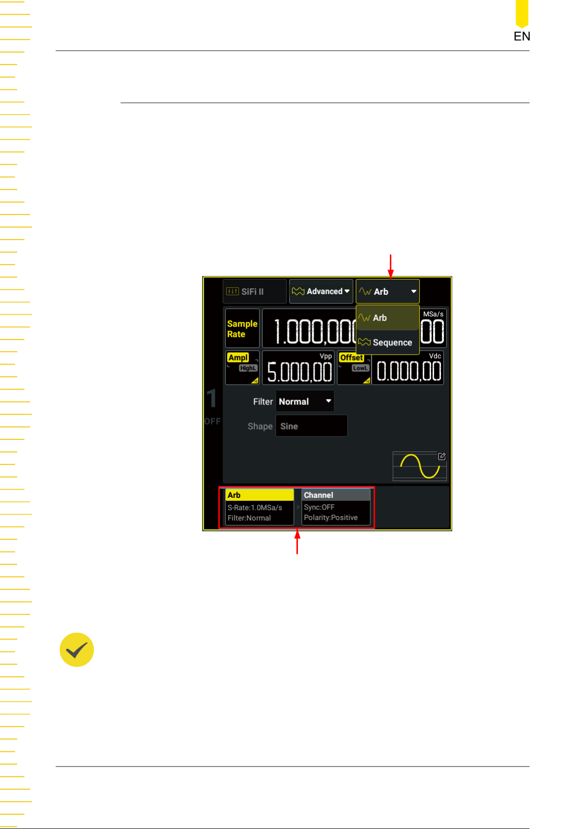
Advanced Mode
9
Advanced Mode
DG800 Pro supports two Advanced output modes: Arb and Sequence.
In the interface as shown in
button to select "Advanced" and access the Advanced Waveform Setting Interface, as
shown in the figure below. You can click or tap one of the tabs at the bottom to
access the Advanced Waveform Setting Interface or Channel Setup Interface. For
Channel Setup Interface, please refer to
the advanced waveform settings.
Figure 4.6
, click or tap the "Output Mode" drop-down
Channel Setup
. This chapter only describes
Sub Mode
TIP
The Advanced mode on/off status of CH1 and CH2 is always synchronized for two-channel
models.
DG800 Pro User Guide
80
Tabs
Figure 9.1 Advanced Waveform Setting Interface
Copyright ©RIGOL TECHNOLOGIES CO., LTD. All rights reserved.
Page 89
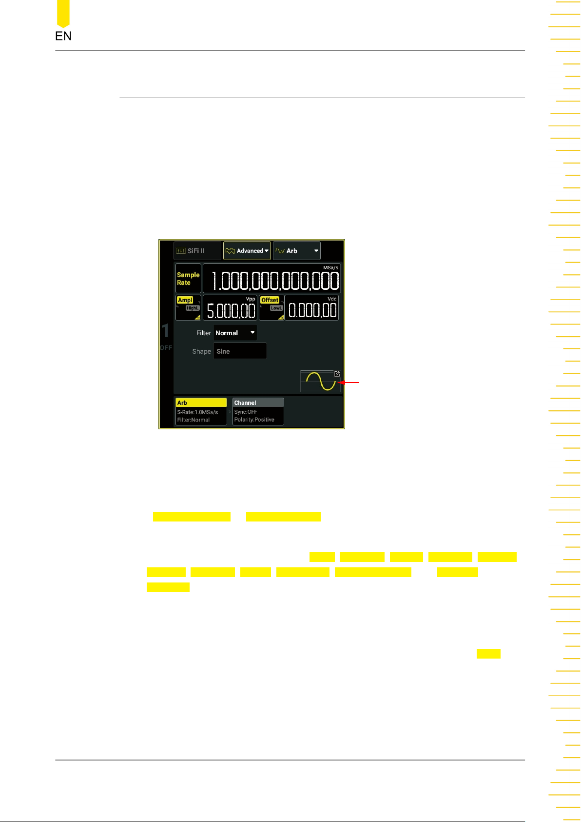
9.1 Arb
DG800 Pro supports Arb output in both Continuous mode and Advanced mode.
Based on the SiFi technology, DG800 Pro can output the arbitrary waveforms point by
point according to the specified sample rate without losing any important points in
the Advanced mode. For the Arb output in the Continuous mode, refer to
Arbitrary Waveforms
In the Advanced Waveform Setting Interface, click or tap the "Sub Mode" drop-down
button to select "Arb" to enter the Arb Setting Interface in the Advanced mode, as
shown in the figure below.
Advanced Mode
To Output
.
Waveform Preview/Selection
Figure 9.2 Arb Setting Interface
Select the Data Source
In the Arb Setting Interface, click or tap the "Waveform Preview/Selection" area and
select
• Built-in waveforms: stored in the instrument's internal non-volatile memory,
• Stored waveforms: Arb files (*.arb/*.csv/*.txt) stored in the instrument's internal
Built In Wforms or Stored Wforms in the displayed menu.
containing 11 types of waveforms: Basic, Common, Engine, Seg Mod, Bioelect,
Medical, Standard, Maths, Trigonome, Anti Trigonome, and Window
Function. Basic waveforms include Sine, Square, Ramp, and Noise. For details
about other built-in waveforms, refer to
memory (C disk) or in the external memory (D disk). After "Stored Wforms" is
selected, select the Arb file that you want to load and then click or tap
After loading, the data in the current volatile memory space will change. For
descriptions of the three Arb file formats, refer to
Waveforms
.
Table 5.2 Built-in Waveforms
To Output Arbitrary
.
Load.
Copyright ©RIGOL TECHNOLOGIES CO., LTD. All rights reserved. DG800 Pro User Guide
81
Page 90
Advanced Mode
TIP
• When built-in waveforms are selected, the waveform length is fixed to 16,384 pts. When
• DG800 Pro does not support loading Arb files with file headers. It is recommended to use
Set the Filter Mode
"Stored Wforms" is selected, the available Arb length ranges from 32 pts to 2 Mpts (8
Mpts optional).
Ultra Station 00.02.01.00.01 or later to generate Arb waveforms and untick the "Save File
With Header" box when saving the file.
Click or tap the
• Normal: It has wide and flat frequency response as well as short edge time, but
the step response produces a large overshoot.
• Step: It has more ideal step response, narrow bandwidth, longer rise/fall time,
and longer edge time.
• Interpolation: It guarantees the output of signals with no distortion at all.
Set the Waveform Parameters
Click or tap the Sample Rate input field to set the sample rate for the Arb waveform.
The available range is from 1 μSa/s to 312.5 MSa/s. The output frequency is
automatically calculated according to the number of waveform points: Output
Frequency = Sample Rate/Waveform Points.
For other waveform parameters, refer to
9.2 Sequence
A sequence is a combination of multiple individual waveforms in order. In Sequence
mode, you can self-define the sequence and save the edited sequence to internal
memory or external storage device (*.seq format).
Filter drop-down button to select the filter mode.
Continuous
.
In the Advanced Waveform Setting Interface, click or tap the "Sub Mode" drop-down
button to select "Sequence" to enter the Sequence Setting Interface, as shown in the
figure below.
DG800 Pro User Guide
82
Copyright ©RIGOL TECHNOLOGIES CO., LTD. All rights reserved.
Page 91
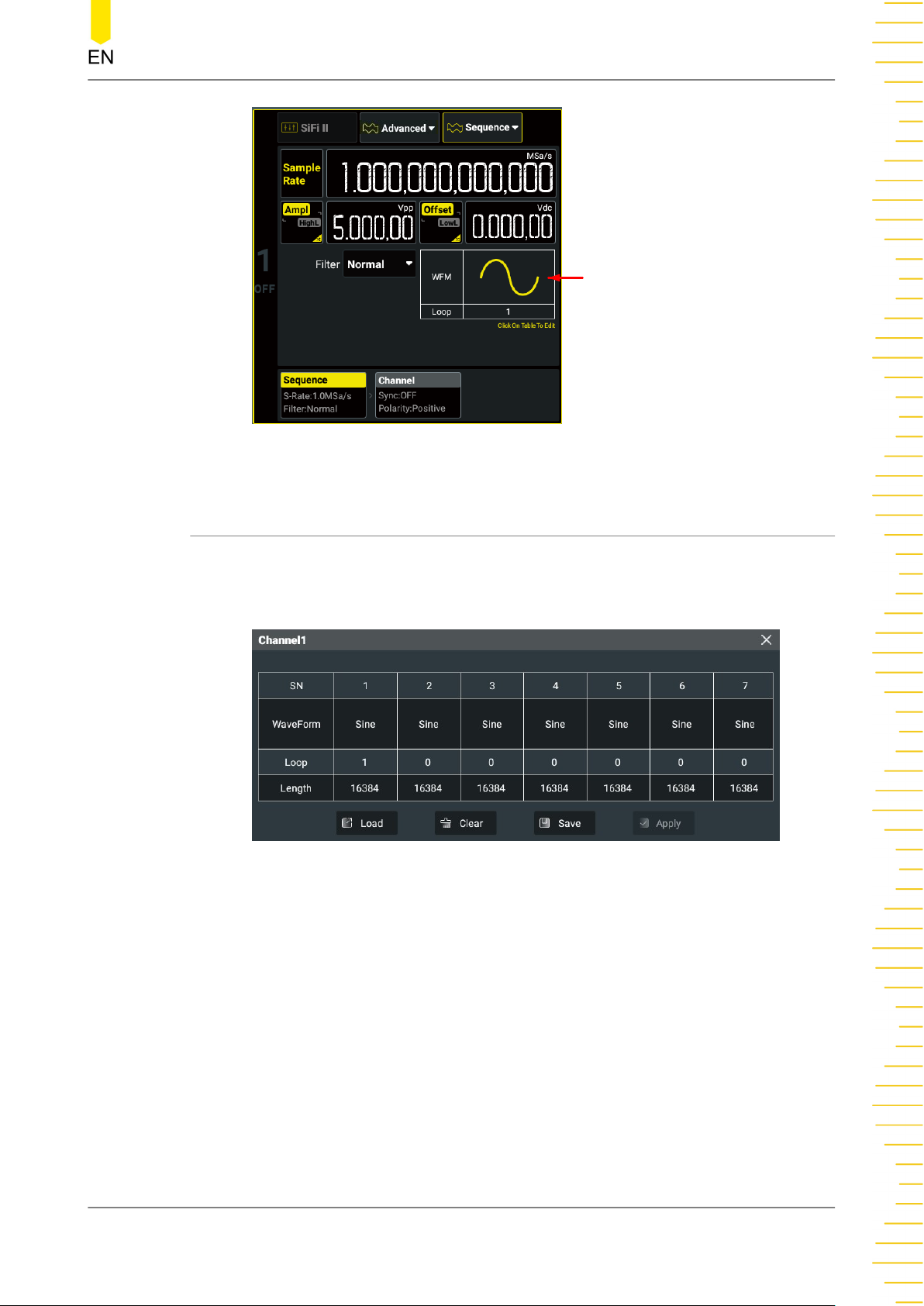
Sequence Preview/Editing
Figure 9.3 Sequence Setting Interface
Advanced Mode
9.2.1 To Edit Sequence
In the Sequence Setting interface as shown in
Preview/Editing" area to open the sequence editing table, as shown in the figure
below.
• SN: displays the step number from 1 to 64. Slide the table left and right to view
all the steps.
Figure 9.3
, click or tap the "Sequence
Figure 9.4 Sequence Editing Table
• WaveForm: displays the wave type for step n. Click or tap the cell in this row to
set the waveform for the specified step.
• Loop: displays the repeat count for step n. Click or tap the cell in this row to set
the repeat count for the specified step.
• Length: displays the waveform length for step n. Click or tap the cell in this row
to set the length of the specified step (built-in waveform).
Copyright ©RIGOL TECHNOLOGIES CO., LTD. All rights reserved. DG800 Pro User Guide
83
Page 92
Advanced Mode
After the sequence function is enabled, by default, the table has a Sine step whose
loop is 1. The loops of other steps are 0. You can follow the steps below to edit the
sequence.
1.
Click or tap the cell in the WaveForm row to select the waveform type for the
specified step in the pop-up menu. Built-in waveforms and stored waveforms
(*.arb/*.csv/*.txt) are supported. The available data length of the stored waveform
that can be loaded: 32 pts to 2 Mpts (8 Mpts/CH optional).
TIP
For descriptions of the three Arb file formats, refer to
To Output Arbitrary Waveforms
.
2. Click or tap the cell in the Loop row to set the loop with the pop-up numeric
keypad for the specified step. The maximum value is 256. When the entry loop is
set to 0, the entry has no output.
3.
When selecting the built-in waveform, click or tap the cell in the Length row to set
the data length of the specified step with the pop-up numeric keypad. The data
length ranges from 32 pts to 2 Mpts (8 Mpts/CH optional). The total points of all
valid steps (the loop is not 0) in the current sequence cannot exceed 2 Mpts (8
Mpts/CH optional).
TIP
When selecting the stored waveforms, you cannot set the data length.
4. After editing, click or tap Apply to confirm modifications and set the sequence as
the waveform of the current channel.
If you want to clear the current step configurations, click or tap
Clear and the table
will be restored to its default state.
9.2.2 To Save/Load Sequence
Save Sequence
After editing a sequence, you can save the sequence to the internal memory or
external storage device.
1. In the interface as shown in
displayed.
2. Enter the target path in the internal/external memory. Click or tap
virtual keypad is displayed.
3. Set the sequence name with the pop-up virtual keypad and then click or tap Enter
to save the sequence. Then you can see the sequence that you saved under the
target path.
DG800 Pro User Guide
84
Figure 9.4
, click or tap Save and the "Store" menu is
Save and the
Copyright ©RIGOL TECHNOLOGIES CO., LTD. All rights reserved.
Page 93
Advanced Mode
Load Sequence
You can load the sequence files stored in the internal memory or external storage
device.
1. In the interface as shown in
Figure 9.4
displayed.
2. Enter the target path in the internal/external memory and tick the sequence file
(*.seq) that you want to load.
3. Click or tap
Load and the instrument will open the file in the sequence editing
table and apply to the current channel.
TIP
For general operations of the "Store" menu, please refer to
9.2.3 To Set Sequence Parameters
In the interface as shown in
Sample Rate
Click or tap the Sample Rate input field to set the sample rate for the sequence. The
sample rate ranges from 1 μSa/s to 312.5 MSa/s, and the default is 1 MSa/s.
Figure 9.3
, you can also set the following parameters.
, click or tap Load and the "Store" menu is
Storage Management
.
Amplitude/High Level
Refer to
To Output Sine Wave
to set the amplitude/high level. Note that Vrms and
dBm are not available for the unit of the sequence amplitude.
Offset/Low Level
Refer to
To Output Sine Wave
to set the offset/low level.
Filter Mode
Click or tap the
Normal: It has wide and flat frequency response as well as short edge time, but
•
Filter drop-down button to select the filter mode.
the step response produces a large overshoot.
• Step: It has more ideal step response, narrow bandwidth, longer rise/fall time,
and longer edge time.
• Interpolation: It guarantees the output of signals with no distortion at all.
Copyright ©RIGOL TECHNOLOGIES CO., LTD. All rights reserved. DG800 Pro User Guide
85
Page 94
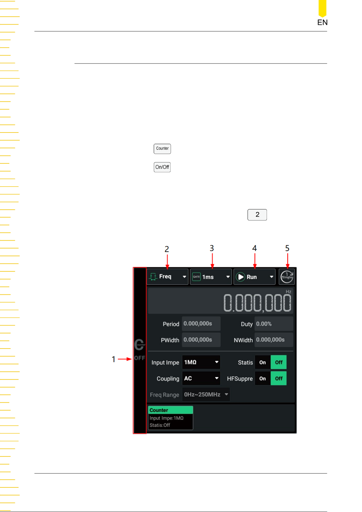
Frequency Counter
10
Frequency Counter
DG800 Pro series provides the frequency counter function. It allows you to measure
the frequency, period, duty cycle, positive pulse width and negative pulse width for
the external input signal. The counter measuring signal is applied to the front-panel
[Counter] connector. You can enter the counter setting menu in the following ways
(for two-channel models):
• Click or tap the Counter label at the bottom of the interface to access the
"Counter" menu.
• Press the front-panel
• Press the front-panel
counter function.
When the counter menu is enabled (for two-channel models), the original CH2
configuration area is replaced by the counter menu, as shown in the figure below.
Click or tap the CH2 channel label or press the front-panel
counter menu.
key to access the "Counter" menu.
key to access the "Counter" menu and enable the
to disable the
DG800 Pro User Guide
86
Figure 10.1 Counter Menu
Copyright ©RIGOL TECHNOLOGIES CO., LTD. All rights reserved.
Page 95
1. Counter On/Off Identifier
2. Measurement Item Drop-down button
3. Gate Time Drop-down button
4. Operating Status Drop-down button
5. Single Measurement Key
10.1 To Enable the Counter
Press the front-panel key to enable the counter function. You can also click or
tap the counter on/off identifier in the counter menu to enable the counter function.
After the counter is enabled, "ON" will be displayed in the counter on/off identifier
and the counter label is highlighted.
Frequency Counter
TIP
When the counter is enabled, the output of CH2 will be disabled for two-channel models. You
are not allowed to configure CH2.
10.2 To Set the Counter
In the "Counter" menu, you can set the following parameters for the counter.
Measurement Parameter
Available parameters include frequency (default), period, duty cycle, positive pulse
width, and negative pulse. In the "Counter" menu, click or tap the "Measurement
Item" drop-down button to select the measurement item. The selected measurement
item is displayed. When the statistical function is enabled, the statistical information
of this item will be displayed (
Operating Status
In the "Counter" menu, click or tap the "Operating Status" drop-down button to set
the counter operating status to "Run", "Stop", or "Single".
Statistical Function
).
• Run: measures the input signal continuously based on the current configuration.
• Single: performs a single measurement and then enters the "Stop" state. You can
also click or tap the key to perform a single measurement (in any operating
status).
• Stop: completes the current measurement and then stops.
Copyright ©RIGOL TECHNOLOGIES CO., LTD. All rights reserved. DG800 Pro User Guide
87
Page 96
Frequency Counter
Gate Time
In the "Counter" menu, click or tap the "Gate Time" drop-down button to set the gate
time to Auto, 1 ms, 10 ms, 100 ms, 1 s, 10 s, 100 s, 1000 s, or 10,000 s. The default is
Auto.
Input Impedance
In the "Counter" menu, click or tap the
Ω" or "1 MΩ" (default).
High Frequency Suppression
When the input impedance is set to 1 MΩ, the HF Suppression function is available. In
low-frequency signal measurements, this function can be used to filter the highfrequency components (>60 kHz) in a way to improve the measurement accuracy.
In the "Counter" menu, click or tap the HFSuppre on/off switch to enable or disable
the HF Suppression function.
Coupling Type
In the "Counter" menu, click or tap the
"AC". Note that the coupling type is fixed to "DC" when the input impedance is set to
50 Ω.
• DC: DC coupling, both the DC and AC components of the signal under test can
pass the channel.
• AC: AC coupling, the DC components of the signal under test are eliminated.
Input Impe drop-down button to select "50
Coupling drop-down button to select "DC" or
Frequency Range
In the "Counter" menu, click or tap the
frequency range.
• When the input impedance is set to 50 Ω, you can set the frequency range to 0
Hz~250 MHz, 250 MHz~500 MHz.
• When the input impedance is set to 1 MΩ, the frequency range is fixed to 0 Hz~
250 MHz.
Statistical Function
Please refer to
Statistical Function
10.3 Statistical Function
The statistical function can calculates the maximum, minimum, average, and standard
deviation of the current measurement parameter automatically and displays the
variation of the measurement values in "Digital" or "Curve" display mode. In the
counter setting interface (
Figure 10.1
Freq Range drop-down button to select the
.
), click or tap the Statis on/off switch to enable
DG800 Pro User Guide
88
Copyright ©RIGOL TECHNOLOGIES CO., LTD. All rights reserved.
Page 97
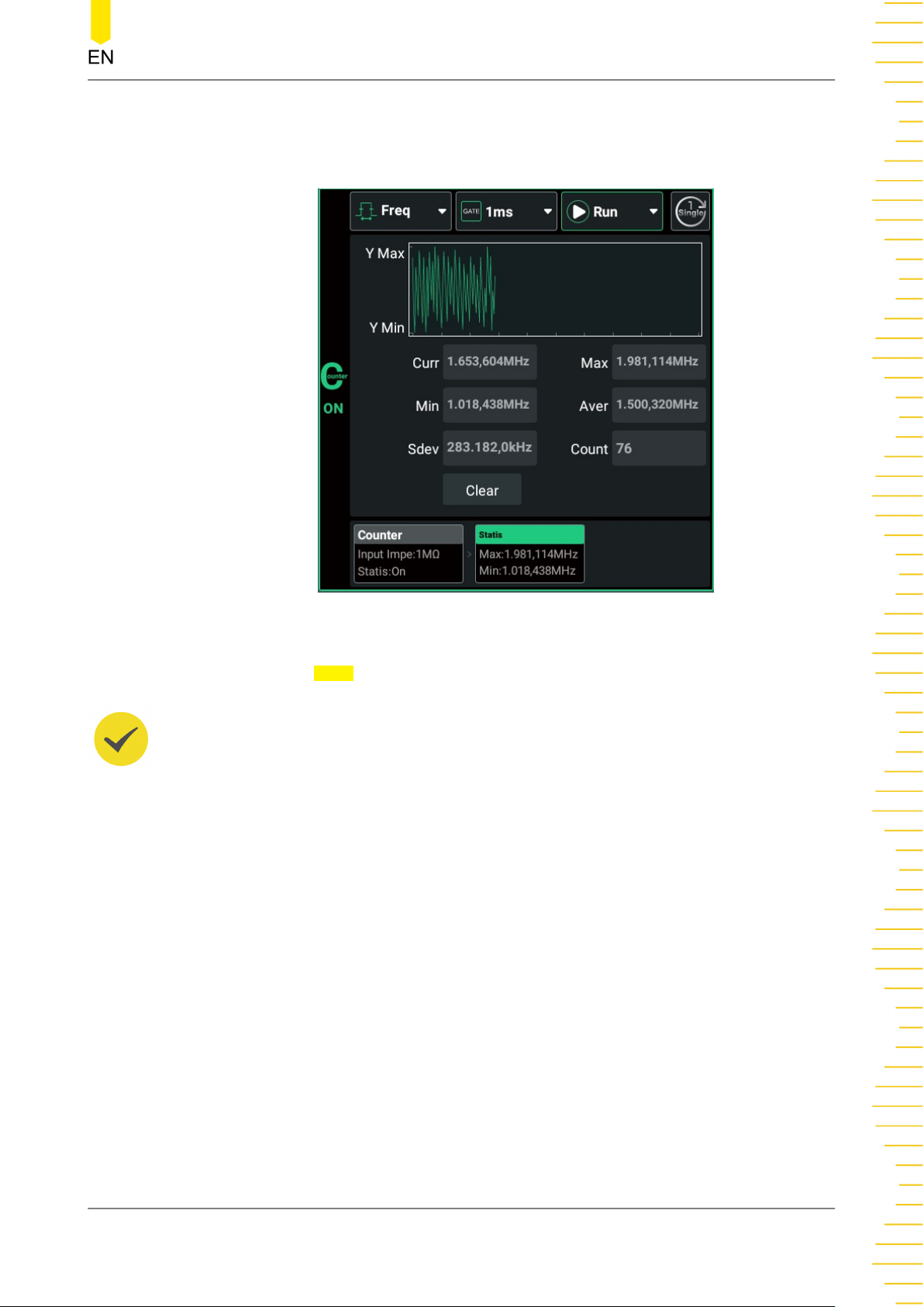
Frequency Counter
or disable the statistical function. After the statistical function is enabled, you can click
or tap the "Statis" tab to enter the statistical interface, as shown in the interface
below.
Figure 10.2 Counter Statistical Interface
Click or tap the
Clear key to clear the current results. The count will restart from 1.
TIP
The maximum count is 256 for the counter measurements. If the measurement count exceeds
256, the instrument will clear measurement data and restart the count.
Copyright ©RIGOL TECHNOLOGIES CO., LTD. All rights reserved. DG800 Pro User Guide
89
Page 98
Channel Copy
11
Channel Copy
DG800 Pro supports the Channel Copy function between two channels, allowing you
to copy the states of one channel to the other one. DG821 Pro should have the twochannel upgrade option installed. The copy information is as shown in the table
below.
Click or tap
menu. You can perform the copy operation between two channels:
• Click or tap CH1 > CH2 to copy the states and waveforms of CH1 to CH2.
• Click or tap CH2 > CH1 to copy the states and waveforms of CH2 to CH1.
• Click or tap Swap to exchange the states of CH1 and CH2.
TIP
The Channel Copy function is disabled when channel track is enabled.
Channel Copy at the bottom of the screen to open the channel copy
Table 11.1 Dual-channel operation parameters
(√ indicates available; × indicates not available; * indicates available in certain
conditions)
Parameter Track Copy
Basic Functions
Channel Output State × ×
Output Mode √ √
Basic Waveform √ √
Frequency √ √
Frequency Coupling Disabled Disabled
Period √ √
Amplitude √ √
Amplitude Coupling Disabled Disabled
Offset √ √
Phase √ √
Phase Coupling Disabled Disabled
Square Duty Cycle √ √
Ramp Symmetry √ √
Pulse Width √ √
Rising Edge √ √
Trailing Edge √ √
Arb Type √ √
Harmonic Type √ √
DG800 Pro User Guide
90
Copyright ©RIGOL TECHNOLOGIES CO., LTD. All rights reserved.
Page 99
Parameter Track Copy
Harmonic Order √ √
Harmonic Combination √ √
Order Harmonic Amplitude √ √
Order Harmonic Phase √ √
Combine Harmonic Amplitude
List
√ √
Combine Harmonic Phase List √ √
Burst
State √ √
Mode √ √
(Trigger) Source √ √
Delay √ √
Cycles √ √
Period √ √
Phase √ √
Gate Polarity √ √
Idle Level √ √
Sweep
State √ √
Mode √ √
Trigger Source √ √
Start Frequency √ √
Stop Frequency √ √
Center Frequency √ √
Frequency Span √ √
Start Hold Time √ √
Stop Hold Time √ √
Sweep Time √ √
Return Time √ √
Mark On/Off √ √
Mark Frequency √ √
Modulation
Modulation Type √ √
Modulation Source √ √
Modulating Waveform √ √
Modulation Frequency √ √
Modulation Depth √ √
DSSC √ √
Frequency Deviation √ √
Phase Deviation √ √
Duty Cycle Deviation √ √
Width Deviation √ √
Channel Copy
Copyright ©RIGOL TECHNOLOGIES CO., LTD. All rights reserved. DG800 Pro User Guide
91
Page 100
Channel Copy
Parameter Track Copy
Modulation Polarity √ √
Modulation Rate √ √
Modulation Amplitude √ √
Hop Frequency √ √
Phase √ √
SUM Waveform √ √
SUM Frequency √ √
SUM Ratio √ √
Channel
Sync On/Off √ √
Sync Port √ √
Sync Polarity √ √
Invert √ √
Impedance √ √
Trigger output √ √
DG800 Pro User Guide
92
Copyright ©RIGOL TECHNOLOGIES CO., LTD. All rights reserved.
 Loading...