

Page 1

-1-
Page 2

保证和声明
1. 请使用所在国家认可的本产品专用电源线。
9. 怀疑产品出故障时,请勿进行操作。
警告
注意
版权
©2018 苏州普源精电科技有限公司
商标信息
RIGOL 是苏州普源精电科技有限公司的注册商标。
文档编号
QGB11000-1110
声明
本公司产品受中国及其它国家和地区的专利(包括已取得的和正在申请的专利)保护。
本公司保留改变规格及价格的权利。
本手册提供的信息取代以往出版的所有资料。
本手册提供的信息如有变更,恕不另行通知。
对于本手册可能包含的错误,或因手册所提供的信息及演绎的功能以及因使用本手册而导致的
任何偶然或继发的损失,RIGOL 概不负责。
未经 RIGOL 事先书面许可,不得影印、复制或改编本手册的任何部分。
产品认证
RIGOL 认证本产品符合中国国家产品标准和行业产品标准及 ISO9001:2015 标准和
ISO14001:2015 标准,并进一步认证本产品符合其它国际标准组织成员的相关标准。
联系我们
如您在使用此产品或本手册的过程中有任何问题或需求,可与 RIGOL 联系:
电子邮箱:service@rigol.com
网址:www.rigol.com
一般安全概要
2. 请确保产品可靠接地。
3. 查看所有终端额定值。
4. 请使用合适的过压保护。
5. 请勿开盖操作。
6. 请勿将异物插入排风口。
7. 请使用合适的保险丝。
8. 避免电路外露。
安全术语和符号
本手册中的安全术语:
警告性声明指出可能会造成人身伤害或危及生命安全的情况或操作。
10. 请保持适当的通风。
11. 请勿在潮湿环境下操作。
12. 请勿在易燃易爆的环境下操作。
13. 请保持产品表面的清洁和干燥。
14. 请注意防静电保护。
15. 请注意搬运安全。
16. 请正确使用前面板 BNC 输出连接器,仅允许
信号输出。
注意性声明指出可能导致本产品损坏或数据丢失的情况或操作。
1
Page 3

产品上的安全术语:
DANGER
表示您如果不进行此操作,可能会立即对您造成危害。
WARNING
表示您如果不进行此操作,可能会对您造成潜在的危害。
CAUTION
表示您如果不进行此操作,可能会对本产品或连接到本产品的其他设备造成
高电压
安全警告
保护性接地端
壳体接地端
测量接地端
注意
警告
提示
RIGOL
产品上的安全符号:
保养与清洁
保养
请勿将仪器放置在长时间受到日照的地方。
清洁
请根据使用情况定期对仪器进行清洁。方法如下:
1. 断开电源。
2. 用柔和的清洁剂或清水浸湿软布擦拭仪器外部,请注意不要将水或其他异物通过散热孔进入机
箱内。清洁带有液晶显示屏的仪器时,请注意不要划伤 LCD 显示屏。
文档概述
本文档介绍初次使用DG800系列函数/任意波形发生器时需要了解的信息,包括产品简介、连接电
源、开机检查以及远程控制等。
本手册的最新版本可登陆
文档格式的约定
1. 按键:
本手册中通常用“文本框+文字(加粗)”表示前面板上的一个按键,如 Utility。
2. 菜单标签:
本手册通常用“字符底纹+文字(加粗)”表示一个菜单标签,如系统设置。
3. 连接器:
本手册中通常用“方括号+文字(加粗)”表示前面板或后面板上的一个连接器。例如:
[Counter]。
损坏。
请勿使任何腐蚀性的液体沾到仪器上,以免损坏仪器。
重新通电之前,请确认仪器已经干透,避免因水分造成电气短路甚至人身伤害。
网址(www.rigol.com)进行下载。
2
Page 4
4. 操作步骤:
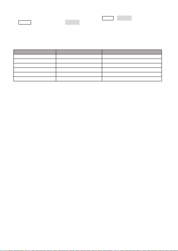
型号
通道数
最大输出频率
DG812 2 10MHz
DG811 1 10MHz
DG822 2 25MHz
DG821 1 25MHz
DG832 2 35MHz
DG831 1 35MHz
本手册中通常用箭头“”表示下一步操作。例如:Utility系统设置表示按下前面板上的
Utility 功能键后再触摸点击 系统设置 菜单标签。
文档内容的约定
DG800系列函数/任意波形发生器包含以下型号。如无特殊说明,本手册以DG832为例介绍其使用
方法。
一般性检查
1. 检查运输包装
如运输包装已损坏,请保留被损坏的包装或防震材料,直到货物经过完全检查且仪器通过电性
和机械测试。
因运输造成仪器损坏,由发货方和承运方联系赔偿事宜。RIGOL 公司恕不进行免费维修或更
换。
2. 检查整机
若存在机械损坏或缺失,或者仪器未通过电性和机械测试,请联系您的 RIGOL 经销商。
3. 检查随机附件
请根据装箱单检查随机附件,如有损坏或缺失,请联系您的 RIGOL 经销商。
产品简介
DG800 系列函数/任意波形发生器是一款集函数发生器、任意波形发生器、 噪声发生器、脉冲发
生器、谐波发生器、模拟/数字调制器、频率计等功能于一身的多功能信号发生器。多功能、高性
能、高性价比、便携式、触摸屏操作等特点为教育、研发、生产、测试等行业提供了新的选择。
前面板、后面板和用户界面(显示屏)的简要介绍请分别参考图 1、图 2 和图 3。
3
Page 5
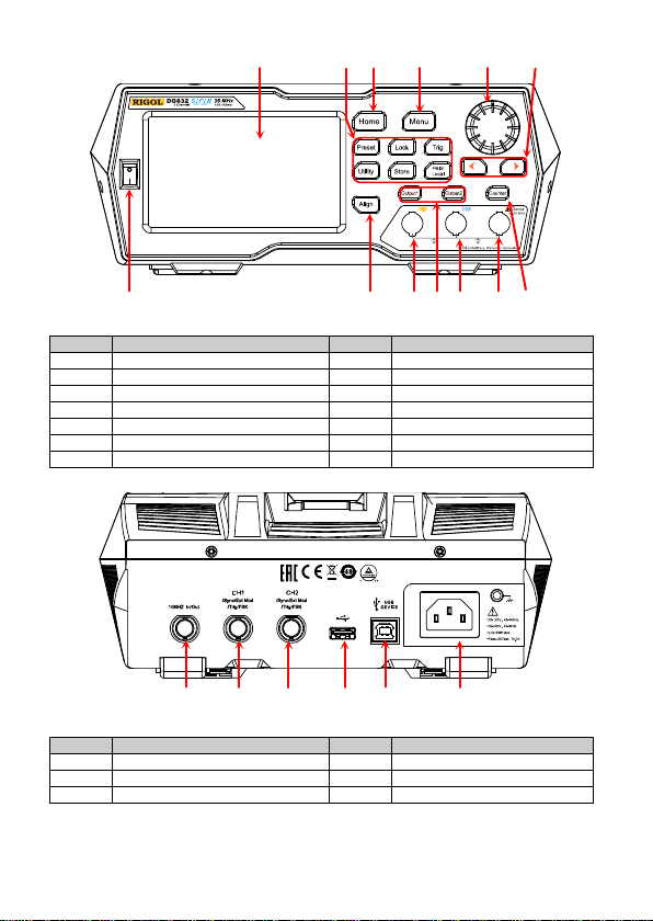
编号
说明
编号
说明 1 电源键 8 方向键 2 同相位键
9
旋钮 3 CH1 输出连接器
10
Menu 键
4
通道控制区
11
Home 键
5
CH2 输出连接器
12
功能键 6 Counter 测量信号输入连接器
13
LCD 触摸显示屏
7
频率计
——
——
编号
说明
编号
说明
1
10MHz 输入/输出连接器
4
USB HOST
2
CH1同步/
5
USB DEVICE
3
CH2 同步/外调制/触发连接器
6
AC 电源插口
1 2 3 4 5 6 7
13 12 11 10 9 8
表 1 前面板说明
图 1 前面板
1 2 3 4 5 6
表 2 后面板说明
外调制/触发连接器
图 2 后面板
4
Page 6

编号
名称
说明
通道输出配置
2
上下滑动条
提示用户可上下滑动屏幕,查看或设置参数。
:打开 Store 界面。
4
右箭头
提示用户可向右滑动屏幕,切换至波形选择界面。
:表示前面板按键和屏幕被锁定。
6
波形
显示各通道当前选择的波形。
7
界面标签
显示当前界面的标签。
8
频率
显示各通道当前波形的频率。
9
幅度
显示各通道当前波形的幅度。
10
偏移
显示各通道当前波形的直流偏移。
11
相位
显示各通道当前波形的相位。
8
1 2 3
7 6 5 4
9
10
11
表 3 用户界面标识
1
状态栏
3 信息设置
5 状态栏
使用前准备
连接电源
请使用附件提供的电源线将信号发生器连接至 AC 电源中,如下图所示。本信号发生器支持
100-127V,45-440Hz 或 100-240V,45-65Hz 规格的交流电源,最大输入功率不超过 30W。当通
过该连接器将信号发生器连接到交流电源时,仪器自动调节至正确的电压范围,无需手动选择电
压范围。
图 3 用户界面
显示各通道当前的输出配置。
:打开 Utility 界面。
:执行通道复制功能。
:执行屏幕打印操作。
:表示关闭蜂鸣器。
:表示仪器处于程控模式。
:表示使用网线成功将仪器连接至局域网。
:表示成功连接U盘。
5
Page 7

注意
开机检查
正确连接电源后,按下前面板的电源键 打开信号发生器。开机过程中仪器执行初始化过程和自
检过程。结束后,屏幕进入默认界面。
设置系统语言 DG800 支持多种语言菜单。您可以按 Utility系统设置,然后触摸点击 Language 标签右侧的
参数选择框,选择所需的语言类型。
使用内置帮助系统
DG800 对于前面板上的每个功能按键以及当前显示界面都提供了帮助信息。用户可在操作仪器的
过程中随时查看各项帮助信息。
1. 获取前面板按键帮助
按下 Help/Local 键,然后再按下你所需要获得帮助的前面板按键,仪器界面显示该键的帮
助信息。
2. 获取常用帮助主题
按下前面板 Help/Local 键,弹出如下图所示的界面,触摸点击屏幕中“帮助”,进入帮助列
表界面。此时,您可通过上下滑动屏幕或旋转旋钮滚动列表,然后触摸点击选中相应的帮助项,
仪器界面显示该项的帮助信息。
3. 获取界面数据说明
按下前面板 Help/Local 键,弹出界面如上图所示。然后触摸点击屏幕“中间”,可显示对当
前界面中间部分数据的解释说明;触摸点击“顶部”,可显示对当前界面上部分数据的解释说
明;触摸点击“底部”,可显示对当前界面下部分数据的解释说明;触摸点击“向导”,可进入
为避免电击,请确保仪器正确接地。
6
Page 8

向导界面提示您进行操作。
4. 帮助的翻页操作
当帮助信息为多页显示时,您可通过手指上下滑动屏幕以滚动帮助信息页面。
5. 关闭当前的帮助信息
当仪器界面显示帮助信息时,用户按下前面板 Help/Local 键,将关闭当前显示的帮助信息。
实例:输出正弦波
本节主要介绍如何从[CH1] 连接器输出一个正弦波(频率为 20kHz,幅度为 2.5Vpp,偏移量为
500mVdc,起始相位为 90°)。
1. 选择输出通道:按下前 面板 Output1 键(或通过触摸点击通道输出配置状态栏 )
选中 CH1 通道。此时通道界面以红色显示。
2. 选择正弦波:按下前面板 Menu 键,在弹出的波形选择界面触摸点击 Continuous“Sine”
图标,仪器自动跳转至正弦波参数设置界面。
3. 设置频率:触摸点击频率标签右侧的参数输入框,通过弹出的数字键盘输入 20,选择单位
“kHz”,点击“Ok”。
4. 设置幅度:触摸点击幅度标签右侧的参数输入框,通过弹出的数字键盘输入 2.5,选择单位
“Vpp”,点击“Ok”。
5. 设置偏移电压:触摸点击偏移标签右侧的参数输入框,通过弹出的数字键盘输入 500,选 择 单
位“mVdc”,点击“Ok”。
6. 设置起始相位:触摸点击相位标签右侧的参数输入框,通过弹出的数字键盘输入 90,选择单
位“°”,点击“Ok”。
7. 启用通道输出:按 Output1 键( 或通过触摸点击通道输出配置状态栏 ,在通道设
置界面打开通道输出), Output1 键背灯点亮并且通道状态条呈高亮状态(即 ),
[CH1]连接器以当前配置输出正弦波信号。
8. 观察输出波形:使用 BNC 连接线将 DG800 的[CH1]与示波器相连接,由示波器观察输出波形。
远程控制
DG800 系列函数/任意波形发生器可以通过 USB 或 GPIB(配合 RIGOL 的 USB-GPIB 转接模块)
接口与计算机进行通信从而实现远程控制。远程控制基于 SCPI( Standard Commands for
Programmable Instruments)命令集实现。DG800 支持两种远程控制方式:用户自定义编程和使
用 PC 软件(如 RIGOL Ultra Sigma)。
当仪器处于远程控制状态时,前面板按键以及触摸屏被锁定(电源开关键 和 Help/Local 键
除外)。此时,您可以按 Help/Local 退出远程模式。
更多产品信息
1. 获取设备信息
按 Utility系统信息,您可获取设备信息,包括设备型号、设备序列号以及软件版本号。
2. 查看选件安装状态
按 Utility选件,您可查看所有选件的安装状态。
欲了解本产品更多信息,请查阅相关手册(您可登录RIGOL网站www.rigol.com下载)。
《DG800用户手册》:提供本产品的功能介绍及操作方法、远程控制方法、在使用过程中可能出
现的故障及处理方法以及订货信息;
《DG800编程手册》:提供本产品的SCPI命令集以及编程实例;
《DG800数据手册》:提供本产品的主要特色和技术指标。
7
Page 9

Guaranty and Declaration
1. Only the exclusive power cord designed for
9. Do not operate the instrument with
output signal.
WARNING
result in serious injury or death.
Copyright
© 2018 RIGOL (SUZHOU) TECHNOLOGIES I NC. A ll Rig h ts Reserved.
TrademarkInformation
RIGOL is a registered trademark of RIGOL (SUZHOU) TECHNOLOGIES INC.
PublicationNumber
QGB11100-1110
Notices
RIGOL products are covered by P.R.C. and foreign patents, issued and pending.
RIGOL reserves the right to modify or chan ge p ar t s o f or all th e specifications and pricing
policies at the company’s sole decision.
Information in this p u blication replaces all p r eviously released mate r ials.
Information in this publication is subject to change without notice.
RIGOL shall not be lia ble for ei ther i nci dental or consequential losses in connection w ith the
furnishing, use, or performance of this manual, as well as any information contained.
Any part of this doc ument is forbidde n to be c opie d, photoc opied, o r rear range d withou t prior
written approval of RIGOL.
ProductCertification
RIGOL guarantees that this product conforms to the national and industrial standards in China
as well as the ISO9001:2015 stan dard and the ISO14001:2015 st an dard. Other international
standard conformance cer tifications are in p r ogress.
ContactUs
If you have any problem or require ment when us ing our products or thi s manual , plea se contact
RIGOL.
E-mail: service@rigo l.com
Website: www.rigol.com
General Safety Summary
the instrument and authorized for use
within the local country could be used.
2. Ensure that the instrument is safely
grounded.
3. Observe all term inal ratings.
4. Use proper ov ervolt ag e protection.
5. Do not operate without covers.
6. Do not insert objects into the air outlet.
7. Use the prop er fuse.
8. Avoid circuit or w ir e exposure.
Safety Notices and Symbols
Safety Notices in this Manual:
Indicates a potentially h a za r dous situation or practice which, if not avoided, will
suspected failures.
10. Provide adequate ventilation.
11. Do not operate in wet conditions.
12. Do not operate in an explosive
atmosphere.
13. Keep instrument surfaces clean and dry.
14. Prevent elect ro st atic impact.
15. Handle with caution.
16. Please use the fron t-panel BNC output
connector correctly. It is only allowed to
1
Page 10

CAUTION
Indicates a poten tially hazardous situation or practice which, if not avoided,
could result in damage to the product or loss of important data.
DANGER
It calls attention to an operation, if not correctly performed, could result in
injury or hazard immediately.
WARNING
It calls attention to an operation, if not correctly performed, could result in
potential injury or hazard.
CAUTION
It calls attention to an operation, if not correctly performed, could result in
damage to the product or oth er devices connected to the product.
Hazardous
Voltage
Safety
Warning
Protective Earth
Terminal
Chassis Ground
Test Ground
WARNING
the instrument is completely dry before connecting it to the power supply.
Tip
(www.rigol.com).
SafetyTerms on the Product:
Safety Symbols on the Product:
Care and Cleaning
Care
Do not store or leave the instrument where it may be exposed to direct sunlight for long periods
of time.
Cleaning
Clean the instrument regularly according to its operating conditions.
1. Disconnect th e in st r u m en t f r om all p ow er sou r ces.
2. Clean the external surfaces of the instrument with a soft cloth dampened with mild detergent
or water. Avoid having any water or other objects into the chassis via the heat dissipation
hole.When cleaning the LCD, take care to avoid scarifying it.
CAUTION
To avoid damage to the instrument, do not expose it to caustic liquids.
To avoid short-circuit resulting from moisture or person al injuries, ensu re that
Document Overview
This manual introduces some basic information that you should know when you use the DG800
series function/arbitrary wavefo rm generator fo r the first time. It contains the following contents:
product overview, how to connect the instrument to the AC power, turn-on checkout, and
remote control.
For the latest version of this manual, download it fro m th e o f ficial website of RIGOL
2
Page 11

Format Conventions in this Manual
Model
No. of Channels
Max. Output Frequency
DG812 2 10 MHz
DG811 1 10 MHz
DG822 2 25 MHz
DG821 1 25 MHz
DG832 2 35 MHz
DG831 1 35 MHz
1. Keys:
The keys on the front panel are usually denoted by the format of "Key Name (Bold) + Text
Box". For example, Utility.
2. Menu Labels:
The menu labels are usually denoted by the format of "Menu Word (Bold) + Character
Shading". For example, System Setting.
3. Connectors:
The connectors on the front or rear panel are usually denoted by the format of "Connector
Name (Bold) + Square Brackets (Bold)". For example, [Counter].
4. Operation Procedures:
"" represents the next step of operation. For example, UtilitySystem Setting indicates
pressing Utility on the front panel and then pressing the menu label System Setting.
Content Conventions in this Manual
DG800 series function/arbitrary waveform generator includes the follow in g models. Unless
otherwise specified, this manual takes DG832 as an example to illustrate the operation methods
of the DG800 series.
General Inspection
1. Inspe c t the packaging
If the packaging has been damaged, do not dispose the damaged packaging or cushioning
materials until the shipment h as b een c h ec k ed f or completeness and has passed both
electrical and mechanical t ests.
The consigner or carrier shall be liable for the damage to t h e in st r u m en t resultin g from
shipment. RIGOL would not be resp o n sib le fo r fr ee m ain t en an c e/r ew or k or replacement of
the instrument.
2. Inspect the instrument
In case of any mechanical d am a ge, missing parts, or failur e in p a ssing the electrical and
mechanical tests, contact your RIGOL sales representative.
3. Check th e accessories
Pleasecheck the accessories according to the packing lists. If the accessories are damaged or
incomplete, please contact y o u r RIGOL sales representative.
3
Page 12

Product Overview
No.
Description
No.
Description
1
Power Key
8
Arrow Keys
2
Align Phase Key
9
Knob
3
CH1 Output Connector
10
Menu Key
4
Channel Control Area
11
Home Key
5
CH2 Output Connector
12
Function Keys
Counter Measurement Sig n al
Input Connector
7
Frequency Counter
——
——
1 2 3 4 5 6 7
13 12 11 10 9 8
As a multi-functional signal generator, DG800 series function/arbitrary waveform generator
integrates many instruments into 1, such as function generator, arbitrary waveform generator,
noise generator, pulse generator, harmonic generator, analog/digital modulator, and frequency
counter. As a multi-functional and portable instrument, it offers you a new choice in education,
R&D, production, measurement, an d other industries with its user-friendly touch screen and
high performance at an unprecedented price point.
For descriptions of the front pan el, ref er t o Figure 1; for desc r ip tions of the rear panel, refer to
Figure 2; and for descript ion s of the user interface (LCD), refer to Figure 3.
Table 1 Front Panel Desc r iption
Figure 1 Front Panel
6
13 LCD Touch Screen
1 2 3 4 5 6
Figure 2 Rear Panel
4
Page 13

Table 2 Rear Panel Descr iption
No.
Description
No.
Description
1
10MHz In/Out Connector
4
USB HOST
2
CH1 Sync/Ext Mod/Trig/FSK Connector
5
USB DEVICE
3
CH2 Sync/Ext Mod/Trig/FSK Connector
6
AC Power Cord Connector
No.
Name
Description
Channel Output
Status Bar
Up and Down
Scroll Bar
Prompts you to move up and down with your fingers on
the screen to view and set parameters.
: opens the Store interface.
: performs the screen print operation.
Prompts you to slide right on the sc r een t o switch t o t h e
waveform selection interface.
: indicates that the front-panel keys and the screen are
: indicates that a USB storage d ev ice is f ou n d.
6
Waveform
Displays the currently selected wa veform of e a ch channel .
7
Interface Label
Displays the label of the current interface.
Displays the frequency of the current waveform of each
channel.
Displays the amplitude of the current waveform of each
channel.
8
1 2 3
7 6 5 4
9
10
11
Table 3 User Interface Icons
1
Configuration
2
Information
3
Setting
4 Right Arrow
5 Status Bar
8 Frequency
9 Amplitude
Figure 3 User Interface
Displays the current output configuration of the channel.
: opens the Utility interface.
: performs the channel copy function.
locked.
: indicates that the beeper is d isab led .
: indicates that the instr u m en t is in
programming-controlled mode.
: indicates that the instr u m en t has been su c cessfully
connected to the local area network by using the netwo rk
cable.
5
Page 14

10 Offset
Displays the DC offset of the current waveform of each
channel.
Displays the phase of the current waveform of each
channel.
CAUTION
11 Phase
To Prepare for Use
To Connect to AC Power
Please use the power cord provided in the accessories to connect the signal generator to the AC
power source, as shown in the figure below. The rated AC power source supported by the signa l
generator is (100-127 V, 45-440Hz) or (100-240 V, 45-65Hz), and its maximum input power s hal l
not exceed 30 W. When the signal generator is connected to the AC power source via the power
cord, the instrument automatically adjusts itself to within the proper voltage range, and you do
not need to select the voltage range manually.
Turn-on Checkout
After connecting the instrument to the power source properly, press on the front panel to
start the signal generator. During the start-up, the instrument will undergo the initialization and
self-check process. Then, it will enter a d efault interface.
To Set the System Language
DG800 arbitrary waveform generator sup ports multiple languages. You can press
UtilitySystem Se tting, and then select a desired language from the Language drop-down
list.
To Use the Built-in Help System
DG800 series provides the h elp in f or ma t ion f or each f r on t-panel function menu and the current
display interface. You can view the help information if you have any questions during the
operation process.
1. Obtain the help informa tio n of the front panel keys
To get the he l p info rmati on about the fro nt -panel keys, press the Help/Local key first, and
then press the desired key fo r the help in formation. The n, the corresponding hel p informati on
is displayed.
To avoid electric shock, ensure that the instrument is correct ly grounded.
6
Page 15

2. Obtain the common help topics
Press Help/Local on the front panel, and then the following interface is displayed below.
Tap "Help" to enter the help interf ace. At this time , you can tap on the touch s creen to mo ve
up and down the help items or rotate the knob to scroll up and down the list to select the
desired help item. Then, the help in f or m at ion f o r the item is displayed in the interface.
3. Obtain the descriptions of the data in the interface
Press Help/Local on the front panel to enter the interface, as shown ab ove. Tap "Center"
to view the descriptions for the data in the center of the current interface. Tap "Top" to view
the descriptions for the data in the top part of the current interface. Tap "Bottom" t o v i ew
the descriptions for the data in the bot tom part of the curre nt interface . Tap "Guide" to enter
the guide interface.
4. Page up/down operation
When the help information is dis pl a yed in multiple pages, you c a n ta p to m o ve u p a nd do w n
the touch screen to view the help information.
5. Close the current help information
When the help information is displayed in the interface, press Help/Local on the front panel
to close the help information currently displayed on the screen.
Example: To Output Sine
This section mainly introduces how to output Sine waveforms ( freque ncy 2 0 kHz , a mplitude 2. 5
Vpp, offset 500 mVdc, start phase 90°) f r om the [CH1] connector.
1. Select the output channel: Press Output1on the front panel or tap the channel output
configuration status bar to select CH1. At this time, the ch an n el is ind ica t ed in
red in the status bar.
2. Select Sine waveforms: Press Menu on the front panel, and then the waveform selection
interface is displayed. Tap Continuous and then select the "Sine"icon to go to the sine
waveform parameter setting interface aut o matically.
3. Set frequency: Tap the Freq parameter input field to input 20 with the pop-up numeric
keypad, and then select "kHz" as the unit. Tap "Ok".
4. Set amplitude: Tap t h e Ampl parameter input field to input 2.5 with th e pop-up numeric
keypad, and then select "Vpp" as the unit. Tap "Ok".
5. Set offset voltage: Tap t h e Offset parameter input field to input 500 with the pop-up
numeric keypad, and then select "mVdc " as the unit. Tap "Ok".
7
Page 16

6. Set start phase: Tap the Phase parameter input field to input 90 with the pop-up numeric
keypad, and then select "°" as t h e unit . Tap "Ok".
7. Enable channel output: Press Output1 or tap the channel output configuration status
bar to enable the channel output. Then,the backlight of Output1 key is
illuminated and t he channel status is highlighted ( ), and the Sine signal is output
from the [CH1] connector based on the current configurations.
8. Observe the output waveforms: Connect the [CH1] connector of the DG800 series t o
the oscilloscope by using the BNC cable, and then you can view the output waveforms from
the oscilloscope.
Remote Control
DG800 series function/arbitrary waveform generator can be connected to the PC via the USBor
GPIB (working with RIGOL USB-G PIB interface converter) to realize remote control. The remote
control can be realized by using SCPI (Standard Commands for Programmable Instruments)
commands. DG800 series signal generator supports tw o ways of r em ote control: user-defined
programming and PC software (e.g. RIGOL Ultra Sigma).
When the instrument is in remote control, the front panel keys (except the Power key and
Help/Local key) and the tou c h scr een ar e locked. At t h is t ime, you can press Help/Local to
exit the remote mode.
More Product Information
1. Obtain the device in format io n
Press UtilitySystem Info to obtain the information of the instrument, including the
device model, device serial n u mber, as well as software v ersion number.
2. Check the option inst alla t ion
Press UtilityOption to view the inst a llat io n status of all the o p tions.
For more information about this instrument, refer to the relevant manuals by logging in to the
official web site of RIGOL (www.rigol.com) to download them.
DG800 User's Guide
remote control methods, p ossible failures and solutions in using th e in st r u m en t , an d o rder
information;
DG800 Programming Guide
instances of the instrument.
DG800 Datasheet
: introduces the functions of the instrument and the operation methods,
: provides de tai le d desc ripti ons of SC PI c omma nds and pro gra mm in g
: provides the main features and technical specifications of the instrument.
8
 Loading...