


RIGOL
User’s Guide
DG800 Series
Function/Arb itrary Waveform
Generator
Jul. 2018
RIGOL (SUZHOU) TECHNOLOGIES INC.


RIGOL
Guaranty and Declaration
Copyright
© 2018 RIGOL (SUZHOU) TECHNOLOGIES INC. All Rights Reserved.
Trademark Information
RIGOL is a registered trademark of RIGOL (SUZHOU) TECHNOLOGIES INC.
Publication Number
UGB11100-1110
Software Version
00.00.01
Software upgrade might change or add product features. Please acquire the latest
version of the manual from RIGOL website or contact RIGOL to upgrade the
software.
Notices
RIGOL produ cts are cov ered by P.R.C. and f oreign pa tents, issue d and pendin g.
RIGOL reserves the right to modify or change parts of or all the specifications
and pricing policies at the company’s sole decision.
Information in this publication replaces all previously released materials.
Information in this publication is subject to change without notice.
RIGOL shall not be liable for either incidental or consequential losses in
connection with the furnishing, use, or performance of this manual, as well as
any information contained.
Any part of th is d ocu ment is f orbi dden to be c opie d, ph oto copie d, o r rea r ran ged
without prior written approval of RIGOL.
Product Certification
RIGOL guarantees that this product conforms to the national and industrial
standards in China as well as the ISO9001:2015 standard and the ISO14001:2015
standard. Other international standard conformance certifications are in progress.
Contact Us
If you have any problem or requirement when using our pro du cts or this man ua l,
please contact RIGOL.
E-mail: service@rigol.com
Website: www.rigol.com
DG800 User's Guide I

RIGOL
Safety Requirement
General Safety Summary
Please review the following safety pre cautio ns ca refully before putting the
instrument into operation so as to avoid any personal injury or damage to the
instrument and any product connected to it. To prevent potential hazards, please
follow the instructions specified in this manual to use the instrument properly.
Use the BNC output connector properly.
The BNC output connector on the front panel only allows to output the signal but not
to input the signal.
Use Proper Power Cord.
Only the exclusive power cord designed for the instrument and authorized for use
within the local country could be used.
Ground the Instrument.
The instrument is grounded th rou gh t he Protective Earth lead of the power cord. To
avoid e lectr ic shock, connect the earth terminal of the power cord to the Protective
Earth terminal before connecting any input or output terminals.
Connect the Probe Correctly.
If a probe is used, the probe ground lead must be connected to earth ground. Do not
connect the ground lead to hi gh volta ge. Imp roper w ay of connection could resul t in
dangerous vo l t ages being present on the connectors, controls or other surfaces of
the oscilloscope and probes, which will cause potential hazards for operators.
Observe All Terminal Ratings.
To avoid fire or shock hazard, observe all r atings an d markers on the instrume nt and
check your manual for more information about ratings before connecting the
instrument.
Use Proper Overvoltage Protection.
Ensure that no over voltage (su ch as that cause d by a bolt of lightni ng) can reach the
product. Otherwise, the operator might be exposed to the danger of an electric
shock.
Do Not Operate Without Covers.
Do not operate the instrument with covers or panels removed.
Do Not Insert Objects Into the Air Outlet.
Do not insert objects into the air outlet, as doing so may cause damage to the
instrument.
II DG800 User's Guide

RIGOL
Use Proper Fuse.
Please use the specified fuses.
Avoid Circuit or Wire Exposure.
Do not touch exposed junctions and components when the unit is powered on.
Do Not Operate With Suspected Failures.
If you suspect that any damage may occur to the instrument, have it inspected by
RIGOL authorized personnel before further operations. Any mainte nance,
adjustment or replacement especially to circuits or accessories must be performed
by RIGOL authorized personnel.
Provide Adequate Ventilation.
Inadequate ventilation may cause an increase of temperature in the instrument,
which would cause damage to the instrument. So please keep the instrument well
ventilated and inspect the air outlet and the fan regularly.
Do Not Operate in Wet Conditions.
To avoid short circuit inside the instrument or electric shock, never operate the
instrument in a humid environment.
Do Not Operate in an Explosive Atmosphere.
To avoid personal injuries or damage to the instrument, never operate the
instrument in an explosive atmosphere.
Keep Product Surfaces Clean and Dry.
T o a void dust or moisture from af fecting the pe rformance of the inst rument, keep th e
surfaces of the instrument clean and dry.
Prevent Ele c tr o static Imp a ct.
Operate the instrume nt i n an el ectr ostatic dischar ge protect ive envi ron ment to a vo id
damage induced by static discharges. Always ground both the internal and external
conductors of cables to relea s e sta t i c before making connections.
Use the Battery Properly.
Do not expose the bat tery (if av ailable) t o high temperature or fire. Keep it out of the
reach of children. Improper change of a battery (lithium battery) may cause an
explosion. Use the RIGOL specified battery only.
Handle with Caution.
Please handle with care during transportation to avoid damage to keys, knobs,
interfaces, and other parts on the panels.
DG800 User's Guide III
RIGOL
WARNING
avoided, will result in serious injury or death.
CAUTION
avoided, could result in damage to the product or loss of important data.
DANGER
It calls attention to an operation, if not correctly performed, could
result in injury or hazard immediately.
WARNING
It calls attention to an operation, if not correctly performed, could
result in potential injury or hazard.
CAUTION
It calls attention to an operation, if not correctly performed, could
product.
Hazardous
Voltage
Safety Warning
Protective Earth
Terminal
Chassis Ground
Test Ground
Safety Notices and Symbols
Safety Notic e s in this Manua l:
Indicates a potentially hazardous situation or practice which, if not
Indicates a potentially hazardous situation or practice which, if not
Safety Terms on the Product:
result in damage to the product or other devices connected to the
Safety Symbols on the Product:
IV DG800 User's Guide
RIGOL
CAUTION
WARNING
supply.
Care and Cleaning
Care
Do not store or le ave the instrument where it may be exposed to direct sunlight for
long periods of time.
Cleaning
Clean the instrument regularly according to its operating conditions.
1. Disconnect the instrument from all power sources.
2. Clean the external surfaces of the instrument with a soft cloth dampened with
mild detergent or water . Avoid havin g any water or o ther objects into the chassis
via the heat dissipation hole. When cleaning the LCD, take care to avoid
scarifying it.
To avoid damag e t o the instrument, do not expose it to caustic liquids.
To avoid short-circuit resulting fr om moisture or personal injuries, ensure
that the instrument is completely dry before connecting it to the power
Environmental Consideratio ns
The following symbol indicates that this product complies with the WEEE Directive
2002/96/EC.
Product End-of-Life Handling
The equipment may contain substances that could b e harmf ul to the en vi ronme nt or
human health. To avoid the release of such substances into the environment an d
avoid harm to human health, we recommend you to recycle this product
appropriately to ensure that most materials are reused or recycled properly. Please
contact your local authorities for disposal or recycling information.
You can log in to RIGOL official website (www.rigol.com) to download the latest
version of the RoHS-WEEE certification file.
DG800 User's Guide V

RIGOL
DG800 Series Function/Arbitrary
Waveform Generator Overview
As a multi-functional signal generator, DG800 series function/arbitrar y waveform
generator integrates many instruments into 1, such as function generator, arbitrary
waveform generator, noise generator, pulse generator, harmonic generator,
analog/digital modulator, and frequency counter. As a multi-functional and portable
instrument, it offers you a new choice in education, R&D , produ ction, measure ment,
and other industries with its user-friendly touch screen and high performance at an
unprecedented price point.
Main Features:
Unique SiFi II (Signal Fidelity II) technology: generate the arbitrary waveforms
point by point; recover the signal without distortion; sample rate accurate and
adjustable; jitter of all the output wav e f or ms (including Sine, Pulse, et c .) as lo w
as 200 ps
2 Mpts memor y dept h (sta nda rd); 8 Mpts memory depth (optional) per channel
for arbitrary waveforms
Optional dual-channel with the same performance, equivalent to two
independent signal sources
High frequency stability: ±1 ppm; low phase noise: -105 dBc/Hz
Built-in up to 8 orders harmonics generator
Built-in 7 digits/s, 240 MHz bandwidth full featured frequency counter
Up to 160 built-in arbitrary waveforms, covering the common signals in
engineering application, medical electronics, auto electronics, math processing,
and other various fields
Sample rate up to 125 MSa/s, vertical resolution 16 bits
Arbitrary waveform sequence editing function available; arbitrary waveforms
also can be generated through the PC software
Various analog and digital mo dulati on functions: AM, FM, PM, ASK, FSK, PSK,
and PWM.
Standard waveform combine function, capable of outputting specified
waveforms combined with the basic waveforms
Standard channel tracking function, when enabled, all the parameters of both
channels are updated based on users' configurations
USB HOST&DEVICE interface (standard); USB-GPIB function supporte d
4.3'' TFT color touch screen
RS232, PRBS, and Dualtone outputs supported
VI DG800 User's Guide
RIGOL
Chapter 1 Quick Start
Introduces the appearance and dimensions of
DG800, its front/rear panel, and user interface.
Introduces the main functions and operation
methods of DG800.
Chapter 3 Remote Control
Introduces how to control DG800 remotely.
Chapter 4 Troubleshooting
Lists the possible failures and solutions in using
DG800.
Chapter 5 Appendix
Provides the information about the options and
of DG800.
Model
No. of Channels
Max. Output Frequency
DG812
2
10 MHz
DG822
2
25 MHz
DG832
2
35 MHz
DG811
1
10 MHz
DG821
1
25 MHz
DG831
1
35 MHz
Document Overview
Main Topics in this Manual
Chapter 2 Front Pa nel Operations
accessories list, as well as warranty information
Format Conventions in this Manual
1. Keys:
The keys on the front panel are usually denoted by the format of "Key Name
(Bold) + Text Box". For example, Utility denotes the Utility key.
2. Menu Labels:
The menu labels are usually denoted by the format of "Menu Word (Bold) +
Character Shading". For example, System Setting.
3. Connectors:
The connectors on the front or rear panel are usually denoted by the format of
"Connector Name (Bold) + Square Brackets (Bold)". For e xa mple, [Counter].
4. Operation Procedures:
"" repre sents th e next step o f operation. For example, Utility System
Setting denotes that first press Utility on the front panel, and then tap the
System Setting menu label.
Content Conventions in this Manual
1. DG800 series function/arbitrary waveform generator includes the following
models: This manual takes DG832 as an example to illustrate the operation
methods of the DG800 series.
DG800 User's Guide VII

RIGOL
2. DG800 series function/arbitrary waveform generator is equipped with two
channels (CH1 and CH2). Unless otherwise specified, this manual takes CH1 as
an example to introduce the operation met ho ds of the generator. The operation
methods of CH2 is the same as that of CH1.
Manuals of this Product
The manuals of this product mainly include the quick guide, user’s guide,
programming guide, data sheet, and etc. For the latest version of this manual,
download it from the official website of RIGOL (www.rigol.com).
VIII DG800 User's Guide

Contents RIGOL
Contents
Guaranty and Declaration ......................................................................... I
Safety Requirement ................................................................................ II
General Safety Summary ........................................................................... II
Safety Not ices and Symbols ...................................................................... IV
Care and Cleaning .................................................................................... V
Environmental Considerations .................................................................... V
DG800 Series Function/Arbitrary Waveform Generator Overview ......... VI
Document Overview .............................................................................. VII
Chapter 1 Quic k S tart ......................................................................... 1-1
General Inspection ................................................................................ 1-2
Appearance and Dime nsions ................................................................... 1-3
Front Panel Overview ............................................................................. 1-4
Rear Panel Overview .............................................................................. 1-8
To Prepare for Use ................................................................................ 1-11
To Connect to AC Pow e r ................................................................. 1-11
Turn-on Checkout .......................................................................... 1-11
To Set the System Language ........................................................... 1-11
User Interface ...................................................................................... 1-12
To Use the Built-in Help System ............................................................. 1-15
Chapter 2 Front Panel Operations ...................................................... 2-1
To Output Bas ic Wavefor m ..................................................................... 2-2
To Select Output Channel ................................................................ 2-2
To Select Bas ic Waveform ................................................................ 2-3
To Set Frequency/Period .................................................................. 2-4
To Set Amplitude/High Level ............................................................ 2-5
To Set Offset/Low Level ................................................................... 2-7
To Set Start Phase .......................................................................... 2-8
To Set Duty Cycle (Square) .............................................................. 2-9
To Set Symmetry (Ramp) ................................................................ 2-10
To Set Pulse Width/Duty Cycle (Pulse) ............................................. 2-11
To Set Rising/Falling Edg e (Pulse) .................................................... 2-12
To Enable Channel Output .............................................................. 2-13
Align Phase ................................................................................... 2-14
Example: To Output Sine ................................................................ 2-15
To Output the Arbitrary Waveform .......................................................... 2-17
To Enable Arbitrary Waveforms........................................................ 2-17
To Select the Waveform .................................................................. 2-17
To Set Parameters .......................................................................... 2-22
To Output Harmonic ............................................................................. 2-23
Harmonic Overview ........................................................................ 2-23
DG800 User's Guide IX

RIGOL Contents
To Set Fundamental Waveform Parameters ...................................... 2-24
To Select Harmonic Type ................................................................ 2-24
To Set Harmonic Order ................................................................... 2-24
To Select Harmonic Amplitude ......................................................... 2-25
To Set Harmonic P hase .................................................................. 2-25
Example: To Output Harmonic ........................................................ 2-25
DC ...................................................................................................... 2-28
To Output Dual-tone Waveform ............................................................. 2-29
To Output Advanced Waveform ............................................................. 2-30
PRBS ............................................................................................ 2-30
RS232 .......................................................................................... 2-31
Sequence ...................................................................................... 2-32
Modulation .......................................................................................... 2-34
Amplitude Modulation (AM) ............................................................ 2-34
Frequency Modulation (FM) ............................................................ 2-38
Phase Modulation (PM) .................................................................. 2-41
Amplitude Shift Keying (ASK) .......................................................... 2-44
Frequency Shift Keying (FSK) .......................................................... 2-47
Phase Shift Keying (PSK) ................................................................ 2-50
Pulse Width Modulation (PWM) ....................................................... 2-53
Sweep................................................................................................. 2-56
To Enable the Sweep Function ........................................................ 2-56
Sweep Type .................................................................................. 2-56
Sweep Time .................................................................................. 2-58
Return Time .................................................................................. 2-58
Start Frequency and Stop Frequency ............................................... 2-59
Center Frequency and Freq uency Span ............................................ 2-59
Sweep Trigger Source .................................................................... 2-60
Marker Freq .................................................................................. 2-61
Start Hold ..................................................................................... 2-62
Stop Hold ..................................................................................... 2-62
Burst .................................................................................................. 2-63
To Enable the Burst Function .......................................................... 2-63
Burst Type .................................................................................... 2-63
Burst Delay ................................................................................... 2-65
Burst Period .................................................................................. 2-66
Idle Level ...................................................................................... 2-66
Burst Trigger Source ...................................................................... 2-67
Gated Polarity ............................................................................... 2-68
Frequency Counter ............................................................................... 2-69
To Enable the Frequency Counter .................................................... 2-69
To Set the Frequency Counter ......................................................... 2-70
Store and Recall ................................................................................... 2-73
Storage System ............................................................................. 2-73
File Type ....................................................................................... 2-74
Categories .................................................................................... 2-74
X DG800 User's Guide

Contents RIGOL
File Operation ................................................................................ 2-75
Seamless Interconnection with Oscilloscope ..................................... 2-79
Channel Setting .................................................................................... 2-81
Output Setting ............................................................................... 2-81
Sync Setting .................................................................................. 2-83
Coupling Setting ............................................................................ 2-85
Waveform Combination .................................................................. 2-89
Common Settings ................................................................................. 2-90
System Setting .............................................................................. 2-90
Interface ....................................................................................... 2-92
System Info ................................................................................... 2-96
Option .......................................................................................... 2-96
Display Setting .............................................................................. 2-96
Print Setting .................................................................................. 2-97
System Utility Function ......................................................................... 2-98
To Restore Preset ........................................................................... 2-98
Channel Copy .............................................................................. 2-102
To Install the Option..................................................................... 2-103
To Lock th e Keyboar d ................................................................... 2-105
Chapter 3 Remote Control .................................................................. 3-1
Remote Control via USB ......................................................................... 3-2
Remote Control via LAN ......................................................................... 3-2
Remote Control via GPIB ........................................................................ 3-4
Chapter 4 Troubleshooting ................................................................. 4-1
Chapter 5 Appendix ............................................................................ 5-1
Appendix A: Accessories and Options ...................................................... 5-1
Append i x B: Warranty ............................................................................ 5-2
Index ....................................................................................................... 1
DG800 User's Guide XI


Chapter 1 Quick Guide RIGOL
Chapter 1 Quick Start
This chapter briefly introduces the appearance and dimensions of DG800 series
function/arbitrary waveform generator, its front/rear panel, and user interface.
Contents in this chapter:
General Inspection
Appearance and Dime nsions
Front Panel Overview
Rear Panel Overview
To Prepare for Use
User Interface
To Use the Built-in Help System
DG800 User's Guide 1-1

RIGOL Chapter 1 Quick Guide
General Inspection
1. Inspect the packaging
If the packa gi ng has be en da m age d, do not dispose the damaged packa gi ng or
cushioning materials until the shipment has been check ed for completeness an d
has passed both electrical and mechanical tests.
The consigner or carrier shall be liable for the d amage to the instrument
resulting from shipment. RIGOL would not be responsible for free
maintenance/rework or replacement of the instrument.
2. Inspect the instrument
In case of any mechanical d amage, missing parts, or failure in passing the
electrical and mechanical tests, contact your RIGOL sales representative.
3. Check the accessories
Please check the accessories according to the packing lists. If the ac cessori es
are damaged or incompl e t e, please contact your RIGOL sales representative.
1-2 DG800 User's Guide
Chapter 1 Quick Guide RIGOL
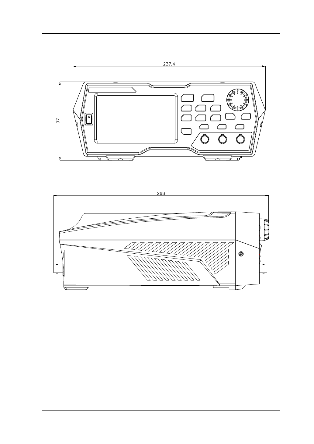
Appearance and Dimensions
Front View Unit: mm
Side View Unit: mm
DG800 User's Guide 1-3
RIGOL Chapter 1 Quick Guide
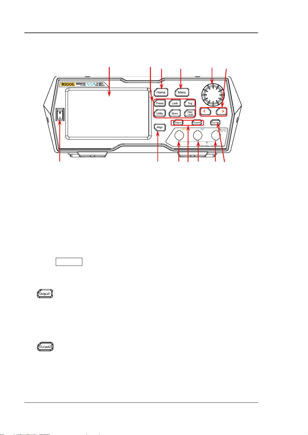
It is used to control the output of CH1.
It is used to control the output of CH2.
backlight turns off.
1 2 3 4 5 6 7
13 12 11 10 9 8
Front Panel Overview
Figure 1-1 Front Panel
1. Power Key
Turns on or off the generator.
2. Align Key
Performs the phase alignment operation. For details, refer to descriptions in
"Align Phase".
3. CH1 Output Connector
BNC connector, with 50 Ω nominal output impedance.
When Output1 is enabled (the backlight turns on), this connector outputs
waveforms according to the current co nfiguration of CH1.
4. Channel Control Area
— Press this key to enable the output of CH1, the backlight
turns on. At this time, the [CH1] connector outputs t he
waveforms according to the current co nfiguration of CH1.
— Press this key ag ain to disable the output of CH1, and the
backlight turns off.
— Press this key to enable the output of CH2, the backlight
turns on. At this time, the [CH2] connector outputs t he
waveforms according to the current co nfiguration of CH2.
— Press this key ag ain to disable the output of CH2, and the
1-4 DG800 User's Guide

Chapter 1 Quick Guide RIGOL
CAUTION
To avoid damages to the instrument, the in put signa l voltage cann ot
exceed ±2.5 V.
5. CH2 Output Connector
BNC connector, with 50 Ω nominal output impedance.
When Output2 is enabled (the backlight turns on), this connector outputs
waveforms according to the current co nfiguration of CH2.
6. Counter Measurement Signal Input Connector
BNC connector, with 1 MΩ input impedance. It is used to receive the signal
measured by the counter.
7. Frequency Counter
Enables or disables the frequency counter.
— Press this key to enable the frequency counter, and the backlight turns on
and blinks continuously.
— Press this key ag ain to disable the frequency counter, and the backlight
turns off. At this time, the frequency c o unter is disabled.
Note: When the freque n c y counter is enabled, no waveforms will be output
from the CH2 connector. When the frequency counter is disabled, waveforms are
allowed to be output from the CH2 connector.
8. Arrow Key
— It is used to move the cursor to select the digit to be edited when you use
the knob to set the parameters (pressing down the knob can enter the
editing mode).
— In the user interface, it is used to move left or right the cursor.
9. Knob
— When you select a menu label in the interface, the knob can be used to
move the cursor down (clockwise) or up (counte rclockwise).
— It can be used to increase (clockwise) or d ecrease (counterclockwise) the
value marked by the cursor when you use the knob to set the parameters
(pressing down the knob can enter the editing mode). Press down the knob
again to exit the editing mode.
— It can be used t o select the desire d wave form by mo ving the cursor w ith the
knob when you se lect the w aveform (pressing the ri ght arrow ke y will locate
the cursor to the right of the interface). Press down the knob to select the
desired waveform .
— When you store or read a file, it can be used to select a storage location or
select a file to be read. Press down the knob t o unfold the currently selected
directory.
— It can be used to select the desired parameter by moving the cursor with
the knob when you set the common information (pressing the r ight arrow
key will locate the cursor to the right of the interface ). Press down the kno b
DG800 User's Guide 1-5
RIGOL Chapter 1 Quick Guide
Restores the instrument to its preset state. At most 10 states can
Locks or unlocks the fr o nt-pane l keys and the to uch screen. In
Used for manual trigger.
mode, the generato r outputs the wavef orms continuously. At
It is used to set the utility function parameters and system
Stores or recalls the instrum ent state or the user-defined
Gets the help information of any front-pan el keys and the help
to select the desired parameter. Then, rotate the knob to modify the
parameter, and press it down again to confirm your modification.
— It is used to select the desired configuration type in the Preset interface.
Press down the knob t o confirm your selection. At this time, a dialog box is
displayed. Use the knob to select the corresponding button, then press
down the knob to perform the corresponding operation (note that only
when the button turns green, can your operation on the knob be valid ).
10. Menu Key
Enters the waveform mode selection interface.
11. Home Key
Enters the main interface of the instrument.
12. Function Keys
be preset.
the unlocked state, press Lock to lock the fro nt-panel keys and
the touch screen. At this time, except the Lock key, all other
keys on the front p anel and the touch screen operation are
invalid. Press the Lock key again to unlock the keys and the
touch screen.
— The default trigger setting for the generator is Internal
trigger. In this mode, when you select the sweep or burst
this time, press the Trig key, and instrument automatically
switches to the manual trigger mode from auto trigger.
— Each time you press the Trig key, one sweep will be
triggered manually or one b urst will be output.
parameters.
arbitrary waveform data. A non-volatile memory (Disk C) is built
in, and a USB storage device (Disk D) can be externally
connected.
information of the curr ent interface.
1-6 DG800 User's Guide

Chapter 1 Quick Guide RIGOL
Note: When the instrument is in the remote mode, press this
key to return to th e local mode.
13. LCD
4.3-inch TFT (480×272) color LCD d isplay. The menu label and parameter
settings of the current function, system state, prompt messages, and other
information can be clearly displayed on the LCD. F or details, refer to descriptions
in "User Interface".
DG800 User's Guide 1-7
RIGOL Chapter 1 Quick Guide
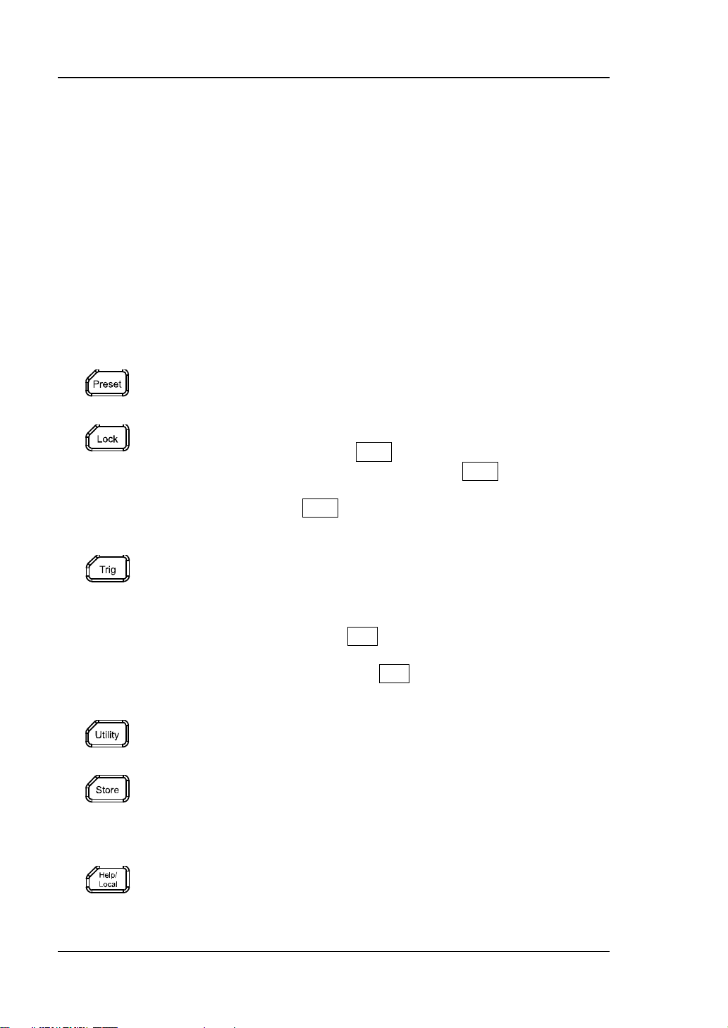
1 2 3 4 5 6
Rear Panel Overview
Figure 1-2 Rear Panel
1. [10MHz In/ Out]
BNC female connector, with 50 Ω nominal impedance. Its function is determined
by the clock type used by the instrument.
1) When internal clock source is selected, this connector (as 10MHz Out)
outputs the 10 MHz clock signal generated by the internal c rystal oscillator
inside the generator.
2) When external clock source is selected, this connector (as 10MHz In)
recei v e s an externa l 10 MHz clock signal.
This connector is usually used to realize synchronization among multiple
instruments. For detai ls about the signals mentioned above , please refer to
the descriptions in "Clock Source".
2. [CH1/Sync/Ext M od/Trig/FSK]
BNC female connector, with 50 Ω nominal impedance. Its function is determined
by the current working mode of CH1.
1) Sync
When the output of CH1 is enabled, this connector outputs the
corresponding sync signal that matches the current conf iguration of CH1.
For detailed information about the characteristics of the sync signals that
correspond to various output signals, refer to the descriptions in "Sync
Setting".
2) Ext Mod
When AM, FM, PM, or P WM of CH1 is enabled and external modulation
source is selected, this connector receives an e xternal modulation signal. Its
input impedance is 1000 Ω. For details, refer to descriptions in
"Modulation".
1-8 DG800 User's Guide

Chapter 1 Quick Guide RIGOL
3) FSK
When ASK, FSK, or PSK of CH1 is enable d and external m odulation source is
selected, this connector receives an external modulation signal whose
polarity can be set by users. Its input impedance is 1000 Ω. For details,
refer to descriptions in "Modulation".
4) Trig In
When Sweep or Burst of CH1 is enabled and external trigger source is
selected, this connector rec eives an external trigger signal whose polarity
can be set by users.
5) Trig Out
When Burst of CH1 is enab led, and the internal/manual trigger source is
selected, this connector outputs a trigger signal with specif ied edge type.
3. [CH2/Sync/Ext M od/Trig/FSK]
BNC female connector, with 50 Ω nominal impedance. Its function is determined
by the current working mode of CH2.
1) Sync
When the output of CH2 is enabled, this connector outputs the
corresponding sync signal that matches the current conf iguration of CH2.
For detailed information about the c haracteristics of the sync signals that
correspond to various output signals, refer to the descriptions in "Sync
Setting".
2) Ext Mod
When AM, FM, PM or PWM of CH2 is enabled and external modulation
source is selected, this connector re ceives an e xternal modulation signal. Its
input impedance is 1000 Ω. For details, refer to descriptions in
"Modulation".
3) FSK
When ASK, FSK, or PSK of CH2 is ena bled and external m odulation source is
selected, this connector rec eives an external modulation signal whose
polarity can be set by users. Its input impedance is 1000 Ω. For details,
refer to descriptions in "Modulation".
4) Trig In
When Sweep or Burst of CH2 is enabled and external trigger source is
selected, this connector rec eives an external trigger signal whose polarity
can be set by users.
5) Trig Out
When Burst of CH2 is enab led, and the internal/manual trigger source is
selected, this connector outputs a trigger signal with specif ied edge type.
4. USB HOST
Supports FAT32 format Flash type USB storage device, RIGOL TMC digital
oscilloscope (DS), and the USB-GPIB interface converter.
USB storage device: reads the wa veform files or state files saved in the U SB
storage device; or stores the current instrument states or edited waveform
data into the USB storage device. Besides, the contents displayed on the
DG800 User's Guide 1-9

RIGOL Chapter 1 Quick Guide
It is used to connect the generator to a computer which can control the
generator remotely by using PC software or by programming.
The rated AC power source supported by the signal generator is (100-127 V,
exceed 30 W. The specification of the fuse is 250 Vac, T4.0 A.
screen can also be saved to the USB storage device in the format of an
image (*.Bmp).
TMC DS: seamlessly int erconnects with the RIGOL DS that meets the TMC
standard. Reads and stores the waveform data collected by the DS and
rebuilds waveforms without distortion.
USB-GPIB interface converter (optional accessory): extends the GPIB
interface for RIGOL instruments that integrates the USB HOST interface
but not the GPIB interface.
5. USB DEVICE
6. AC Power Cord Connector
45-440 Hz) or (100-240 V, 45-65 Hz), and its maximum input po wer shall not
1-10 DG800 User's Guide
Chapter 1 Quick Guide RIGOL
CAUTION
grounded.
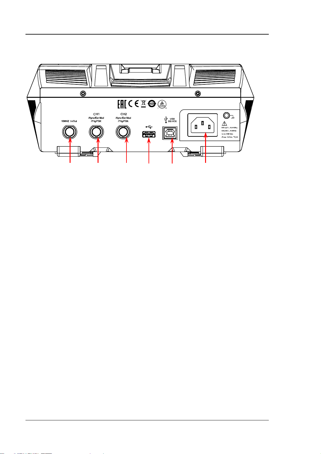
To Prepare for Use
To Connect to AC Power
Please use the power cor d provided in the accessories to connect the signal
generator t o th e AC power source , as shown i n th e figure below . T he r ated AC pow er
source supported by the signal generator is (100-127 V, 45-440Hz) or (100-240 V,
45-65Hz), and its maximum input power shall not exceed 30 W. When the signal
generator is connected to the AC power source via the power c ord, the instrument
automatically adjusts itself to within the proper voltag e range, and you do not need
to select the voltage range manually.
To avoid electric shock, ensure that the instrument is correctly
Turn-on Checkout
After connecti ng th e ins tru ment t o the powe r sou rce pro perly, press
panel to start the signal generator. During the start-up, the instrument will undergo
the initialization and self-check process. Then, it will enter a default interfa ce. If you
still fail to power on the instrument normally, refer to the methods in
"Troubleshooting" to resol v e the prob lem.
on the front
To Set the System Language
DG800 arbitrary waveform generator supports multiple lang uages. You can press
Utility System Setting, and then select a desired lang uage from the
"Language" drop-down list.
DG800 User's Guide 1-11
RIGOL Chapter 1 Quick Guide
Output Impedance Type:
Channel Output State:
Selected Waveform:
1 2 3
6 5 4
7
User Interface
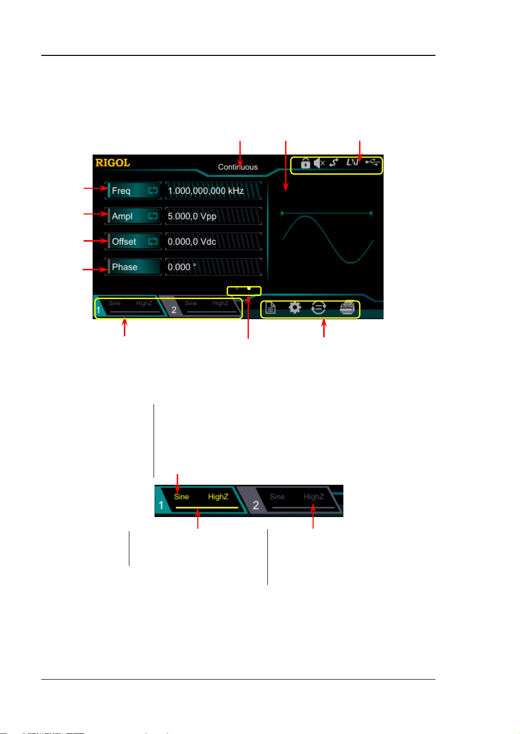
The DG800 user interfac e is shown in the following figure.
8
9
10
Figure 1-1 User Interface
1. Channel Output Configuration Status Bar
Displays the current output configuration of the channel.
Sine/Square/Ramp/Pulse/Noise/Prbs/Dualtone/Harm
/Rs232/DC/Arb/Sequence
Modulation Type: AM/FM/PM/ASK/FSK/PSK/PWM
Sweep Type: Linear/Log/Step
Burst Type: Ncycle/Infinite/Gated
ON: illuminated in yellow.
OFF: grayed out.
Note: Two channels can be enabled simultaneously, but you cannot select both
channels at the same time.
1-12 DG800 User's Guide
High impedance: displays HighZ.
Load: displays impedance (the
default is 50 Ω and the range is
from 1 Ω to 10 kΩ).
Chapter 1 Quick Guide RIGOL
2. Interface Switchover
When left point is grayed out and the right point is illuminated, sliding right on
the touch screen can switch to the waveform selection interface. When the left
point is illuminated and the right point is grayed out, sliding left on the touch
screen can switch to the current interface of waveform parameter setting.
3. Information Setting
: opens the Store interface.
: opens the Utility interface.
: performs the channel c opy function.
: performs the screen print operation.
4. Status Bar
: indicates that the front-panel keys and the screen are locked .
: indicates that the beeper is disabled.
: indicates that the instrument is in programming-controlled mode.
: indicates that the instrument has been successfully connected to the local
area network by using the network cable.
: indicates that a USB storage device is found.
5. Waveform
Displays the currently selected waveform of each channel.
6. Interface Label
Displays the label of the current interface.
7. Frequency
Displays the frequency of the current waveform of each channel. Tap the Freq
parameter input field to modify the parameter with the pop-up numeric keypad.
You c an also use the arrow keys and the knob to modify the paramet er.
8. Amplitude
Displays the amplitude of the current w aveform of each channel. Tap the Ampl
parameter input field to modify the parameter with the pop-up numeric keypad.
You c an also use the arrow keys and the knob to modify the parameter.
9. Offset
Displays the DC offset of the current waveform of each channel. Tap the Offset
parameter input field to modify the parameter with the pop-up numeric keypad.
You c an also use the arrow keys and the knob to modify the parameter.
DG800 User's Guide 1-13

RIGOL Chapter 1 Quick Guide
10. Phase
Displays the phase of the current waveform of each channel. Tap the Phase
parameter input field to modify the parameter with the pop-up numeric keypad.
You c an also use the arrow keys and the knob to modify the parameter.
1-14 DG800 User's Guide
Chapter 1 Quick Guide RIGOL
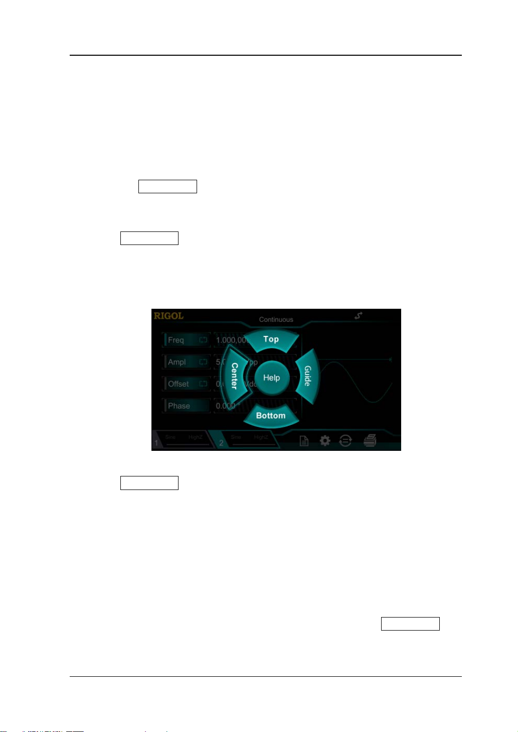
To Use the Built-in Help System
DG800 series provides the help information for each front-panel func tion menu and
the current display interface. You can view the help information if you have any
questions during the operation process.
1. Obtain the help information of the front panel keys
To get the help information ab o ut any front-panel key or menu softkey,
press the Help/Local key f ir st, and then press the desired key for the help
information. Then, the corresponding help infor mation is displayed.
2. Obtain the common help topics
Press Help/Local o n the front panel, and then the following interface is
displaye d below. Tap "Help" to enter the help interface. At this time, you can
tap on the touch screen to move up and d own the help items o r rotate the kno b
to scroll up and down the list to select the desired help item. Then, the help
information for the item is displayed in the interface.
3. Obtain the des c r iptions of the data in the interface
Press Help/Local on the front p anel to enter the interface, as shown above.
Tap "Center" to view the descriptions for the data in the center of the current
interface. Tap "Top" to view the descriptions for the data in the top part of the
current interface. Tap "Bottom" to view the descriptions for the data in the
bottom part of the current interface. Tap "Guide" to enter the guid e interface.
4. Page up/down operation
When the help information is displayed in multiple pages, you can tap to move
up and down the touch screen to view the help information.
5. Close the current help information
When the help information is displayed in the interface, press Help/Local on
the front panel to close the help information currently displayed on the screen.
DG800 User's Guide 1-15


Chapter 2 Front Panel Operations RIGOL
Chapter 2 Front Panel Operations
Introduces the main functions and operation methods of DG800.
Contents in this chapter:
To Output Bas ic Waveform
To Output the Arbitrary Waveform
To Output Harmonic
DC
To Output Dual-tone Waveform
To Output Advanced Waveform
Modulation
Sweep
Burst
Frequency Counter
Store and Recall
Channel Setting
Common Settings
System Utility Function
DG800 User's Guide 2-1

RIGOL Chapter 2 Front Panel Operations
Key Points:
configuration.
To Output Basic Waveform
DG800 series can output basic wa v efor ms (in cludin g Sine, S qua re, Ramp, Pulse, and
Noise) from one channel or from both two channels at the same time. A t start-up,
the dual channels are configured to output a sine waveform with 1 kHz frequency
and 5 Vpp amplitude by default. Users can c onfigure the instrument to output
various basic wavef or ms.
To Select Output Channel
At start-up, the instrument displa ys the CH1 par amete r inte rface by default. You can
press Output1 or Output2 (also, you can tap the channel output configuration
status bar or ) to switch between CH1 and CH2 as the
currently selected channel.
After the desired channel is selected, you c an configure the waveform and
parameters of the selected channel.
CH1 and CH2 cannot be both selected at the same time. You can first select CH1,
after configuring the waveform and parameters of CH1, then select CH2 for
2-2 DG800 User's Guide

Chapter 2 Front Panel Operations RIGOL
Sine
Square
Ramp
Pulse
Noise
Sine
Square
Ramp
Pulse
Noise
Freq/Period
√
√ √ √
Ampl/HighL
√
√ √ √
√
Offset/LowL
√
√ √ √
√
√
√ √ √
Align Phase
√
√ √ √
Duty
√ √
Symmetry
√
Width/Duty
√
RisEdge
√
FallEdge
√
To Select Basi c Waveform
DG800 can output 5 basic w aveforms, in cluding Sine, Square , Ramp, Pulse and Noise.
Press Menu on the front panel, then tap the touch screen to select the desired
waveform. After selecting the desired waveform, you are automatically directed to
the waveform parameter setting interface. To go back to the waveform selection
interface, tap to slide right or press the Menu key on the fron t pa n e l. At start-up,
Sine is selected by default.
Table 2-1 Basic Waveform s
Basic Waveforms
Function Name
Start Phase
DG800 User's Guide 2-3

RIGOL Chapter 2 Front Panel Operations
Sine
Square
Ramp
Pulse
Noise (-3 dB)
1 μHz to
10 MHz
1 μHz to
5 MHz
1 μHz to
200 kHz
1 μHz to
5 MHz
100 MHz
Bandwidth
1 μHz to
25 MHz
1 μHz to
10 MHz
1 μHz to
500 kHz
1 μHz to
10 MHz
100 MHz
Bandwidth
1 μHz to
35 MHz
1 μHz to
10 MHz
1 μHz to
1 MHz
1 μHz to
10 MHz
100 MHz
Bandwidth
To Set Frequency/Period
Frequency is one of the most im portan t par amete rs of basic wav efor ms. F or differe nt
instrument models and w avef orms, the sett ing ranges of frequency a re differen t. The
default frequency is 1 kHz.
DG812/DG811
DG822/DG821
DG832/DG831
The frequency displayed on the screen is the default value or the frequency
previously set. When the instrument function is changed, if this frequency is valid
under the new function, the instrument will still use this frequency; o therwise, the
instrument would display a prompt message and set the frequency to the frequency
upper limit of the new function automatically.
Tap the Freq parameter input field to input the desired frequency value with the
numeric keypad, then selec t the unit. Tap "Ok".
The frequency units available are MHz, kHz, Hz, mHz, and μHz.
Tap the label again to switch to Period setting.
The period units available are s, ms, μs, and ns.
You c an also use the arrow keys and the knob to set the parameter value: press
down the knob to enter the ed iting mode, use the arrow keys to move the cursor to
select the digit to be ed ited, and then rotate the knob to modify the value. Besides,
you can use the knob to switch between differ ent parameters.
2-4 DG800 User's Guide

Chapter 2 Front Panel Operations RIGOL
Key Points:
square value . The default unit is Vpp . Whe n you set the amplitude ,
Vpp=2Vamp
Vrms=0.707Vamp
Vamp
To Set Amplitude/High Level
The amplitude set ting ran ge is limited by the "Impe dance" and "F req/Period" s ettings.
By default, it is 5 V pp.
The amplitude displayed on the screen is the default value or the amplitude
previously set. When the i nstrument configuration (e.g. frequency) is changed, if t his
amplitude is valid, the instrument will still use this amplitude; otherwise, the
instrument would display a prompt message and set the amplitude to the amplitude
upper limit of the new co nfiguration automatically. You can also use "High Level" or
"Low Level" to set the amplitude.
Tap the Ampl parameter input field to input the desired frequency value with the
numeric keypad, then selec t the unit. Tap "Ok".
The amplitude units av aila ble a re Vpp , m Vpp, V rms, mVrms, an d dBm (inv alid in
HighZ).
Tap the label again to switch to High Level setting.
The high level units available are V and mV.
You c an also use the arrow keys and the knob to set the parameter value: press
down the knob to enter the editing mode, use the arrow keys to move the cursor to
select the digit to be ed ited, and then rotate the knob to modify the value. Besides,
you can use the knob to switch between differ ent parameters.
1. How to convert the amplitude in Vpp to the corresponding value in
Vrms?
Method:
Vpp is the unit for signal peak-p eak value and Vrms is the unit for
root-meaninput a decimal point in th e nu meric key pad, a nd th en sele ct a unit. Tap "Ok"
to switch to the unit of the current amplitude.
Remarks:
For different waveforms, the r e lati o n between Vpp and Vrms is different. The
relation of the two units is as shown in the figure below (take sine waveform
as an example).
DG800 User's Guide 2-5

RIGOL Chapter 2 Front Panel Operations
According to the figure above, the conversion relation between Vpp and Vrms
Vrms22Vpp =
erted to a value with Vrms as the unit. For sine waveform, the converted
and the conversion relation
2
1
10lg( )
0.001
Vrms
dBm
RW
= ×
nit dBm is not available when the output impedance is
1.768 Vrms (i. g. 5 Vpp), input a de cimal point in the numeric keypa d and the n
fulfills the following equation:
For example, if the current amplitude is 5 Vpp, input a dec imal point in the
numeric keypad, and then select a unit Vrms. Tap "Ok". Then, it can be
conv
value is 1.768 Vrms.
2. How to set the amplitude of the waveform in dBm?
Method:
1) Press Output1 or Output2 ( also, you can tap the channel outp ut
conf iguration status bar or ) to select the desired
channel.
2) Tap the channel output configuration status bar
(CH2). In the channel setting interface, tap the OutputSet
menu label and select "Off". Then use the numeric keypad to set a proper
load value.
3) Select the desired waveform, tap the Ampl menu label, and then input
the desired value b y using the numeric keypad. Then select the unit
"dBm " fr om the pop-up menu.
Remarks:
dBm is the unit for signal power absolute value,
between dBm and Vrms fulfills the following equation:
(CH1) or
Wherein, R represents the c hannel output impedance value and it must be a
specific value, so the u
"HighZ".
For example, if the current output impedance is 50 Ω and the amplitude is
select "dBm". Tap "Ok" t o convert the amplitude value to the corresponding
value in dBm. The converted value is 17.9601 dBm.
2-6 DG800 User's Guide

Chapter 2 Front Panel Operations RIGOL
To Set Offset/Low Level
The DC offset setting range is limited by the "Impedance" and "Amplitude/High
Level" settings. The default value is 0 V
The DC offset vo ltage displayed on the screen is the default value or the offset
previously set. When the instrument configuration (e.g. impedance) is changed, if
this offset is valid, the instrument will still use this offset; otherwise, the instrument
would display a promp t message and set the offset to the offset upper limit of the
new configuration automatically.
Tap the Offset parameter input field to input the desired offset value with the
numeric keypad, then selec t the unit. Tap "Ok".
The DC offset voltage units available are Vdc and mVdc.
Tap the label again to switch to Low Level setting.
The low level should be at least 1 mV smaller than the high level (output
impedance: 50 Ω).
The low level units available are V and mV.
You c an also use the arrow keys and the knob to set the parameter value: press
down the knob to enter the editing mode, use the arrow keys to move the curso r to
select the digit to be ed ited, and then rotate the knob to modify the value. Besides,
you can use the knob to switch between differ ent parameters.
.
dc
DG800 User's Guide 2-7

RIGOL Chapter 2 Front Panel Operations
To Set Start Phase
The setting range of start phase is fr om 0° to 360°. The default is 0°.
The start phase displayed on the screen is the default value or the phase previously
set. When the instrument function is changed, the new function will still use this
phase.
Tap the Phase parameter input field to input the desired phase value with the
numeric keypad, then selec t the unit "°". Tap "Ok".
You c an also use the arrow keys and the knob to set the parameter value: press
down the knob to enter the editing mode, use the arrow keys to move the cursor to
select the digit to be ed ited, and then rotate the knob to modify the value. Besides,
you can use the knob to switch between differ ent parameters.
2-8 DG800 User's Guide

Chapter 2 Front Panel Operations RIGOL
T
t
Duty Cycle=t/T*100%
To Set Duty Cycle (Square)
Duty cycle is defined as the percentage that the high level takes up in the whole
period (as shown in the figure below). This paramet er is o nly available when Square
or Pulse is selected.
The available range of the duty cycle is from 0.01% to 99.99% (limited by the
current frequency setting). The default is 50%.
Tap the Duty parameter input field to input the desired duty cycle value with the
numeric keypad, then selec t the unit "%". Tap "Ok".
You c an also use the arrow keys and the knob to set the parameter value: press
down the knob to enter the editing mod e, use the arrow keys to m ove the cursor to
select the digit to be ed ited, and then rotate the knob to modify the value. Besides,
you can use the knob to switch between differ ent parameters.
DG800 User's Guide 2-9

RIGOL Chapter 2 Front Panel Operations
T
t
Symmetry=t/T*100%
To Set Symmetry (Ramp)
Symmetry is defined as the percentage that the rising period of the r amp tak es up in
the whole period (as shown in the figure below). This parameter is only available
when Ramp is selected.
The setting range of symmetry is from 0% to 100%. The default is 50%.
Tap the Symm parameter input field to input the desired symmetry value with the
numeric keypad, then selec t the unit "%". Tap "Ok".
You c an also use the arrow keys and the knob to set the parameter value: press
down the knob to enter the editing mode, use the arrow keys to move the cursor to
select the digit to be ed ited, and then rotate the knob to modify the value. Besides,
you can use the knob to switch between differ ent parameters.
2-10 DG800 User's Guide

Chapter 2 Front Panel Operations RIGOL
Pulse
10%
tFall
90%
50%
Pulse Period
To Set Pulse Wi dth/Duty Cycle (Pulse)
Pulse width is defined as the time from the 50% threshold of a pulse's risin g edge t o
the 50% threshold of the next falling edge (as shown in the figure below).
The settable range of the pulse width is from 16 ns to 999.999982118 ks (limited by
"minimum pulse width" and "pulse period"). The default is 500 μs.
Pulse Width ≥ Minimum Pulse Width
Pulse Width < Pulse Period - 2 × Minimum Pulse Width
Pulse duty cycle is d efined as the percentage that the pulse width takes up in the
whole pulse period.
Pulse duty cycle and pulse width are correlative. Modifying either of them (pulse duty
cycle or pulse width) will automatically affect the other. The settable range of the
pulse duty cy cle is from 0.001% to 99.999 % (limited by "minimum pulse width" and
"pulse period"). The default is 50%.
Pulse Duty Cycle ≥ 100 × Minimum Pulse Width ÷ Pulse Period
Pulse Duty Cycle < 100 × (1 - 2 × Minimum Pulse Width ÷ Pulse Period)
Tap the Width parameter input field to input the desired pulse width value with the
numeric keypad, then selec t the unit. Tap "Ok".
The pulse width units available are s, ms, μs, and ns.
Tap this menu label again to switch to duty cyc le setting.
You c an also use the arrow keys and the knob to set the parameter value: press
down the knob to enter the editing mode, use the arrow keys to move the cursor to
select the digit to be ed ited, and then rotate the knob to modify the value. Besides,
you can use the knob to switch between differ ent parameters.
DG800 User's Guide 2-11

RIGOL Chapter 2 Front Panel Operations
Pulse
10%
tRise
tFall
90%
50%
Pulse Period
To Set Rising/Falling Edge (Pulse)
The rising edge time is defined as the duration of the pulse amplitude rising from
10% to 90% thresh old, while f alling edge time is defined as the durati on of the pulse
amplitude moving down from 90% to 10% threshold (as shown in the figure below).
The setting range of rising/falling e dge time is limite d by the currently specified pulse
width limit (as shown in the formula below). DG800 will automatically adjust the
edge time to match the specified pulse width if the value currently set exceeds the
limit value.
Rising/Falling Edge Time ≤ 0.625 × Pulse Width
Tap the RisEdge or FallEdge parameter input field. Use the numeric keypad to
input the desired value and then select the desired unit from the pop-up menu.
The pulse width units available are sec, msec, μsec, and nsec.
The rising and falling edge time are independent of each other, and users can
set them separately.
You c an also use the arrow keys and the knob to set the parameter value: press
down the knob to enter the editing mode, use the arrow keys to move the cursor to
select the digit to be ed ited, and then rotate the knob to modify the value. Besides,
you can use the knob to switch between differ ent parameters.
2-12 DG800 User's Guide

Chapter 2 Front Panel Operations RIGOL
To Enable Channel Output
After configuring the parameters of the waveform selected, enable the channel to
output the waveforms.
Before enabling channel output, you can also tap
then tap the corresponding menu label in the channel setting interface to set the
parameters related with the channel output. For details, refer to descriptions in
"Channel Setting".
Press Output1 or Output2 on the front panel, and then the b acklight turns on. You
can also tap the channel output configuration status bar or
enable the channel output in the channel setting interf ace. When the channel status
bar is highlighted, (i.g.
corresponding output connector on the front panel.
), the configured waveforms ar e output from the
or and
DG800 User's Guide 2-13

RIGOL Chapter 2 Front Panel Operations
CH1
CH2
CH1
CH2
Align Phase
DG800 series dual-channel function/ arbitrary waveform generator enables you to
align the phases of the two channels. Press Align on the front panel, then the
instrument will re-configure the two channels and enable the generator to output
with specified frequency and start phase.
For two signals who se frequencies are the same or in multiple relationship, this
operation can align their phases. For example, assume a sine waveform (1 kHz, 5
Vpp, 0°) is output fr om CH1, while another one (1 kHz, 5 Vpp, 180°) fro m C H2. Us e
the oscilloscope to acquire the w av eforms of t he two channels and sta bly displa y the
waveforms. It can be found that the phase deviation between the two waveforms is
no longer 180°. At this point, press Align on the generator and the waveforms
shown on the oscilloscope will have a phase deviation of 180° without manual
adjustment of the start phase of the generator.
Figure 2-1 Before Aligning Phase
Figure 2-2 After Aligning Phase
2-14 DG800 User's Guide

Chapter 2 Front Panel Operations RIGOL
Example: To Output Sine
This section mainly introduces how to output Sine waveforms (frequency 20 kHz,
amplitude 2.5 Vpp, offset 500 mV
1. Select the output channel: Press Output1 on the front panel or tap the
channel output configuration status bar to se lect CH1.
2. Select Sine waveforms: Press Menu on the front panel, and then the
waveform selection interface is displayed. Tap Continuous and t hen select the
"Sine" icon to go to the sine waveform parameter setting interface
automatically.
3. Set frequency: Tap the Freq parameter input field to input 20 with the pop-up
numeric keypad, and then select the unit "kHz". Tap "Ok".
4. Set amplitude: Tap the Ampl parameter input field to input 2.5 with the
pop-up numeric keypad, and then select "V pp" as the unit. Tap "Ok".
5. Set offset voltage: Tap the Offset parameter input field to input 500 with the
pop-up numeric keypad, and then select "mVdc" as the unit. Tap "Ok".
6. Set start phase: Tap the Phase parameter input field to input 90 with the
pop-up numeric keypad, and then select "°" as the unit. Tap "Ok".
7. Enable channel output: Press Output1 and the backli ght turns on. Also, you
can tap the channel output configuration status bar to enable the
channel output. Then, the channel status is highlighted (i.g.
the Sine signal is output from the [CH1] connector based on the current
configurations.
8. Observe the output waveform: Connect the [CH1] connector of DG800 to
the oscilloscope by using the BNC cable. The w avef orm is as shown in the figure
below.
dc, start phase 90°) from the [CH1] connector.
), and
DG800 User's Guide 2-15

RIGOL Chapter 2 Front Panel Operations
Figure 2-3 Sine Waveform
2-16 DG800 User's Guide

Chapter 2 Front Panel Operations RIGOL
Key Points:
requency of the arbitr ary wavef orms is g reater than
1 MHz, some waveforms will be distorted.
To Output the Arbitrary Waveform
DG800 can output built-in wav eforms f rom a single channel or from two chann els at
the same time. The 160 kinds of built-in arb itrary waveforms are stored in the
internal non-volatile memory.
To Enable Arbitrary Waveforms
Press Menu Continuous "Arb" to enable arbitrary waveform function and
open the arbitrary waveform selection interface, as shown in the figure below.
Figure 2-4 Arbitrary Waveform Selection Interface
To Select the Waveform
DG800 allows users to select 160 built-in waveforms and arbitrary waveforms stored
in the internal or external memory of the instrument.
After selecting the desired waveform, press the corresponding chan nel output
control key (Output1 or Output2), and the specified waveform will be output
from the channel. For details, refer to descriptions in "To Enable Channel
Output
". Note that when the f
DG800 User's Guide 2-17

RIGOL Chapter 2 Front Panel Operations
Type
Waveform
Remarks
Engineering
Sinc
Sinc function
Lorentz
Lorentz function
Log
Logarithm function and the base is 10
GausPul
Gauss pulse
NegRamp
Negative ramp
NPulse
Negative pulse
PPulse
Positive pulse
SineTra
Sine-Tra waveform
SineVer
Sine-Ver waveform
StairDn
Stair-down waveform
StairUD
Stair-up and stair-down waveform
StairUp
Stair-up waveform
Trapezia
Trap ezia waveform
AmpALT
Gain oscillation curve
AttALT
Attenuation oscillation curve
RouHalf
RoundHalf W ave
RousPM
RoundsPM Waveform
Time-velocity curve of explosive
vibration
Time-displacement curve of damped
oscillation
Kinetic energy- time curve of swing
oscillation
Dischar
Discharge curve of Ni-MH battery
Current wa veform of DC brushless
motor
Combin
Combination function
SCR
SCR firing profile
Bworth
Butterworth filter
Chshev1
Chebyshev1 filter
Built-in Waveform
DG800 has 160 built-in arbitrary waveforms, as shown in Table 2-2
waveform selection interface, tap the Engineering, Medical, AutoElec, or Maths
menu label to select the corresponding type. Tap or rotate the knob (pressing the
right arrow key will loc ate the cursor to the right of the interface) to select the
desired waveform (the selected waveform is highlighted). The waveforms under the
Common menu label are most frequently selected o nes by users. At most, 8
waveforms can be stored.
Table 2-2 160 Built-in Arbitrary Waveforms
. In the arbitrary
BlaWave
DampOsc
SwigOsc
Pahcur
2-18 DG800 User's Guide

Chapter 2 Front Panel Operations RIGOL
Chshev2
Chebyshev2 filter
TV
TV sign al
Voice
Voice signal
Surge
Surge signal
Radar
Radar signal
DualTone
Dual-tone signal
Ripple
Power ripple
Quake
Analog quake waveform
Gamma
Gamma signal
StepResp
Step-response signal
BandLim
Bandwidth-limited signal
CPulse
C-Pulse signal
CWPulse
CW pulse signal
GateVibr
Gate self-oscillation signal
LFMPulse
Linear FM pulse signal
MCNoise
Mechanical construction noise
AM
Sectioned sine AM signal
FM
Sectioned sine FM signal
PFM
Sectioned pulse FM signal
PM
Sectioned sine PM signal
PWM
Sectioned PWM signal
Medical
Cardiac
Cardiac signal
EOG
Electro-oculogram
EEG
Electroencephalogram
EMG
Electromyogram
Pulgram
Pulsilogram
ResSpd
Speed curve of the respiration
ECG1
Electrocardi ogra m 1
ECG2
Electrocardi ogra m 2
ECG3
Electrocardi ogra m 3
ECG4
Electrocardi ogra m 4
ECG5
Electrocardi ogra m 5
ECG6
Electrocardi ogra m 6
ECG7
Electrocardi ogra m 7
ECG8
Electrocardi ogra m 8
ECG9
Electrocardi ogra m 9
ECG10
Electrocardi ogra m 10
ECG11
Electrocardi ogra m 11
ECG12
Electrocardi ogra m 12
ECG13
Electrocardi ogra m 13
ECG14
Electrocardi ogra m 14
ECG15
Electrocardi ogra m 15
DG800 User's Guide 2-19

RIGOL Chapter 2 Front Panel Operations
Waveform of the low frequency pulse
electrotherapy
Wavefor m 1 of the nerve stimulation
electrotherapy
Wavefor m 2 of the nerve stimulation
electrotherapy
Wavefor m 3 of the nerve stimulation
electrotherapy
AutoElec
Ignition waveform of the automotive
motor
SP
Automotive starting profile with ringing
Automotive supply voltage profile for
resetting
Automotive transients arising from
disconnection
Automotive transients arising from
inductance in wiring
Automotive transients arising from the
ignition switching off
Automotive transients arising from
switching
Automotive transients arising from
switching
Automotive working pro file during
start-up
Automotive transients arising from
cut-off of bat t e ry power
Automotive transients arising from
cut-off of bat t e ry power
Maths
Airy
Airy function
Besseli
Bessel functions of the first kind
Bessely
Bessel functions of the second kind
Cubic
Cubic function
Dirichlet
Dirichlet function
Erf
Error function
Erfc
Complementary error function
ErfcInv
Inverted complementary error function
ErfInv
Inverted error function
ExpFall
Exponential fall function
ExpRise
Exponential rise function
HavSin
HaverSine function
LFPulse
Tens1
Tens2
Tens3
Ignition
VR
TP1
TP2A
TP2B
TP3A
TP3B
TP4
TP5A
TP5B
2-20 DG800 User's Guide

Chapter 2 Front Panel Operations RIGOL
Laguerre
4-times Laguerre polynomial
Legend
5-times Legend polynomial
Versiera
Versiera
ARB_X2
Square function
Gaussian distribution or normal
distribution
Weibull
Weibull distribution
LogNorm
Logarithmic normal distribution
Laplace
Laplace distribution
Maxwell
Maxwe l l distrib ution
Rayleigh
Rayleigh distribution
Cauchy
Cauchy distribution
CosH
Hyperbolic cosine
CosInt
Integral cosine
Cot
Cotangent
CotHCon
Concave hyperbolic cotangent
CotHPro
Protuberant hyperbolic cot angent
CscCon
Concave cosecant
CscPro
Protubera nt cosecant
CscHCon
Concave hyperbolic cosecan t
CscHPro
Protuberant hyperbolic cose cant
RecipCon
Concave re ci procal
RecipPro
Protubera nt reciprocal
SecCon
Concave secant
SecPro
Protuberant secant
SecH
Hyperbolic secant
SinH
Hyperbolic sine
SinInt
Integral sine
Sqrt
Square root
Tan
Tangent
TanH
Hyperbolic tangent
AbsSine
Absolute value of sine
AbsSinH
Absolute value of half sine
ACos
Arc cosine
ACosH
Arc hyperbolic cosine
ACotCon
Concave a rc cotangent
ACotPro
Protuberant arc cotangent
ACotHCon
Concave arc hyper bolic cotangent
ACotHPro
Protuberant arc hyperbolic cotangent
ACscCon
Concave a rc cosecant
ACscPro
Protuberant arc cosecant
ACscHCon
Concave arc hyperbolic cosecant
ACscHPro
Protuberant arc hyperbolic cosecant
ASecCon
Concave arc secant
Gauss
DG800 User's Guide 2-21

RIGOL Chapter 2 Front Panel Operations
ASecPro
Protuberant arc seca n t
ASecH
Arc hyperbolic sec a n t
ASin
Arc Sinc
ASinH
Arc hyperbolic sin e
ATan
Arc tangent
ATanH
Arc hyperbolic tangent
Bartlett
Bartlett window
BarWin
Modified Bartlett-Hann window
Blkman
Blackman window
BlkmanH
Blackman-Harris window
BohWin
Bohman window
Boxcar
Rectangular window
ChebWin
Chebyshev window
FlatWin
Flat Top weighted window
Ham
Hamming window
Hanning
Hanning window
Kaiser
Kaiser window
Nuttall-defined minimum 4-term
Blackman-Harris window
ParWin
Parzen window
TayWin
Taylor window
Triang
Triangle window (Fejer window)
TukWin
Tukey (tapered cosine) window
NutWin
To Set Parameters
After selectin g the desired wa veform, you a re aut omatically directe d to the wav eform
parameter setting interface.
1. Freq/Period: sets the output frequency/period of the arbitrary waveform.
2. Ampl/HighL: sets the output amplitude/high leve l of t h e arbitrary waveform.
3. Offset/LowL: sets the output offset/low level of the arbitrary waveform.
4. Phase: sets the output start phase of the arbitrary waveform.
Please refer to "To Output Basic Wav eform" to configure the parameters and
output for the channel.
2-22 DG800 User's Guide

Chapter 2 Front Panel Operations RIGOL
......)2sin()2sin()2sin()(
333222111
++++++=
ϕπϕπϕπ
tfAtfAtfAtf
1
f
1
f
1
A
1
ϕ
To Output Harmonic
DG800 can be used as a h armonic generat or to output harmonic with specified order ,
amplitude and phase. It is usually used in the test of harmonic detector devic e or
harmonic filter device. This section introduces how to configure the generator to
output harmonic.
Harmonic Overview
According to Fourier transform, time domain waveform is the superposition of a
series of sine waveforms, as shown in the equation below:
Generally, component with
fundamental wavefor m frequency ,
is the fundamental wavefo rm phase. The frequencies of the other components
(called harmonics) are all integral multiple of the fundamental waveform frequency.
Components whose frequenc ies are odd multiples of the fundamental waveform
frequency are called o dd harmonics, and components whose frequencies are even
multiples of the fundamental waveform frequency are called even harmonics.
At most, 8th harmonic c an be output by DG800. After selecting CH1 or CH2, press
Menu Continuous "Harm" to enter the harmonic setting menu. You can set
fundamental waveform parameters, select the type of output harmonic, specify the
highest order of harmonic, and set the amplitude and phase of each order of
harmonic.
After completing the harmonic parameters setting, press Output1, and the
backlight turns on. The instrument outputs the specified harmonic from the
corresponding output terminal. For details, refer to descriptions in "
Channel Output".
frequency is called fundamental w aveform,
is the fundamental wavef orm amplitude, and
To Enable
is the
DG800 User's Guide 2-23

RIGOL Chapter 2 Front Panel Operations
To Set Fundamental Waveform Parame ters
DG800 allows users to set various fundamental waveform parameters such as
frequency, period, amplitude, DC offse t voltage, high level, low level, and start phase .
It also supports align phase operation. To set the above fund amental waveform
parameters, refer to descriptions in "To Output Basic Waveform".
To Select Har monic Type
DG800 can output even harmonic, odd harmonic, both harmonics, and user-defined
order of harmonic. After entering the harmonic setting interface, tap the Type
parameter selection field to select the desired harmonic typ e.
1. Even: outputs fundamental waveform and even harmonics.
2. Odd: outputs fundamental waveform and odd harmonics.
3. Both: outputs fundamental waveform and all the harmonics in ord er.
4. User: outputs the user-defined orders of harmonics. The highest order is 8.
8 bits binary data are used to represent the output status of the 8 orders of
harmonics respectively. Wherein, 1 represents enabling the output of the
corresponding harmonic, and 0 represents disabling the output of the
corresponding harmonic. You only need to tap the User parameter input f ield,
and then modify the value of each data bit by using the numeric keypad (note
that the leftmost bit repres enting fundamenta l wavef orm is alw ays X and cannot
be modified). For example, if you set the 8 bits data to X001 0001, it indicates
that the fundamental waveform, 4th and 8th orders of harmonics are output.
Note: The actually output harmonics is determined by the currently specified
harmonic order and harmonic type.
To Set Harmoni c Order
The highest order of harmonic output fro m DG800 cannot be greater than the
specif ied value.
After entering the harmonic setting interface, tap the Count parameter selection
field to input a value with numeric keypad.
The range is limited by the maximum output frequency of the instrument and
current fundamental waveform frequency.
Range: 2 to maximum output frequency ÷ fundamental waveform
2-24 DG800 User's Guide

Chapter 2 Front Panel Operations RIGOL
frequency, an integer.
The maximum is 8.
You c an also use the arrow keys and the knob to set the parameter value: press
down the knob to enter the editing mode, use the arrow keys to move the cursor to
select the digit to be edited, and then rotate the k nob to modify the value. Besides,
you can use the knob to switch between differ ent parameters.
To Select Har monic Amplitude
After entering the harmonic setting interface, tap the Harm Ampl parameter input
field to set the amplitude of each order of harmonic.
1) No.: selects the sequence number of the harmonic to be set.
2) Harm Ampl: sets the amplitude of the specified order of harmonic. Use the
numeric keypad to input the amplitude value, and then select the desired unit.
Tap "Ok". The amplitude units available are Vpp, mVpp, Vrms, mVrms, and dBm
(invalid in HighZ).
To Set Harmonic Phase
After entering the harm on i c setting interface, tap the Harm Phase parameter input
field to set the phase of each order of harmonic.
1. No.: selects the sequence number of the harmonic to be set.
2. Harm Phase: sets the phase of the specified order of harmonic. Use the
numeric keypad to input the phase value, and then select the desired unit "°".
Tap "Ok".
Example: To Output Harmonic
This section introduces how to outp ut 2th o rder of harm onic (har monic amplitude: 2
Vpp, harmonic phase: 30°) and 4th orders of harmonic (harmonic amplitude: 1 Vpp ,
harmonic phase: 50°) from the [CH1] connector.
1. Select the output channel: Press Output1 on the front panel or tap the
channel output configuration status bar to select CH1. At this time,
the channel is indicated in red in the status b ar.
DG800 User's Guide 2-25

RIGOL Chapter 2 Front Panel Operations
2. Set fundamental waveform parameters: In this example, various
parameters of the fundamental waveform take the default values. You can also
refer to descriptions in "To Output Basic Waveform" to set various
fundamental waveform parameters such as frequency/period, amplitude/high
level, offset/low level, and start phase.
3. Enable harmonic function: Press Menu on the front panel, and then the
waveform selection interface is displayed. Tap Continuous and t hen select the
"Harm" icon to go to the harmonic parameter setting interface automatically.
4. Set harmonic count: In the harmonic parameter setting interfac e, tap the
Count parameter input field to input a value 5 with pop-up numeric keypad. T ap
"Ok".
5. Select the harmonic type: In the harmonic parameter setting interface, tap
the Type parameter selection field to select the desired even harmonic.
6. Set harmonic amplitude: In the harmonic parameter setting menu, set the
amplitude of 2th and 4th orders of harmonic.
1) Tap the No. parameter input field to input 2 with the pop-up numeric
keypad, and th en tap "Ok".
2) Tap the Harm Ampl parameter inp ut field to input 2 with the pop-up
numeric keypad, select the unit "Vpp". Then tap "Ok".
3) Refer to Step 1 and Step 2 to set the amplitude of the 4th order harmonic to
1 Vpp.
7. Set harmonic phase: In the harmo nic parameter setting menu, set the phases
of 2th and 4th orders o f harmonic in sequence.
1) Tap the No. parameter input field to input 2 with the pop-up numeric
keypad, and then tap "Ok".
2) Tap the Harm Phase parameter input field to input 30 with the pop-up
numeric keypad, select the unit "°". Then tap "Ok".
3) Refer to Step 1 and Step 2 to set the phase of the 4th order harmonic to
50°.
8. Enable channel output: Press Output1, and the backlight turns on. Also,
you can tap the channel output configuration status bar to enable
the channel output. Then, the channel status is highlig hted (i.g.
),
and the fundamental wa veform, 2th and 4th or der of harmoni cs are output f rom
the [CH1] connector based on the current configurations.
9. Observe the output waveform: Connect the [CH1] connector of DG800 to
the oscilloscope by using the BNC cable. The w avef orm is as shown in the figure
below.
2-26 DG800 User's Guide

Chapter 2 Front Panel Operations RIGOL
Figure 2-5 Harmonic
DG800 User's Guide 2-27

RIGOL Chapter 2 Front Panel Operations
DC
DG800 can output DC sign al with amplitude r ange from -10 V to 10 V (HighZ) or from
-5 V to 5 V (when the load is 50 Ω). The figure below shows a sketch of the DC signal.
Press Menu Continuous "DC" to select the DC signal.
Figure 2-6 Sketch of DC signal
Tap the Offset parameter input field to input the d esired offset value with the
numeric keypad, then selec t the unit. Tap "Ok".
You can also use the arrow keys and the knob to set the parameter value: press
down the knob to enter the editing mode, use the arrow keys to move the cursor to
select the digit to be ed ited, and then rotate the knob to modify the value.
2-28 DG800 User's Guide

Chapter 2 Front Panel Operations RIGOL
To Output Dual-tone Waveform
Press Menu Continuous "Dualtone" to enter the dual-tone signal parameter
setting interface.
1. Freq1/CentFreq: sets th e output frequency/period of Signal 1 in the dual-tone
signal.
2. Freq2/OffsFreq: sets the output freque ncy/perio d of Signal 2 in t he dual-tone
signal.
3. Ampl/HighL: sets the output amplitude/high level of the dual-tone sig nal.
4. Offset/LowL: sets the output offset/low level of the dual-tone signal.
Please refer to "To Output Basic Wav eform" to configure the parameters and
output for the channel.
DG800 User's Guide 2-29

RIGOL Chapter 2 Front Panel Operations
6 7 8 9
1 2 3 4 5
XOR
PRBS
To Output Advanced Waveform
DG800 prov ides three advanced waveforms: PRBS, RS232, a nd Sequence.
Note: When one channel is set to one of the advanced waveforms, the other
channel will automatically switch to the set advanced waveform from other
waveform.
PRBS
A PRBS is generated by a linear-feed ba ck shift re giste r (LFSR), as shown belo w.
An LFSR is specified by the number of stages it cont ains (L) and whi ch sta ges (taps)
feed the exclusive-or (XOR) gates in its f ee dback ne twork. The PR BS output is take n
from the last stage. After selecting proper taps, an L-stage LFSR produces a
repetitive PRBS of length 2
of PRBS.
Press Menu Advanced "PRBS" to open the PRBS parameter setting interface.
1. Bit Rate: sets the output bit rate of the PRBS waveform.
2. Ampl/HighL: sets the output amplitude/high level of the PRBS waveform.
3. Offset/LowL: sets the output offset/low level of the PRBS waveform.
4. Data: selects the data type of the PRBS waveform to PRBS7, PRBS9, PRBS11,
resulting in sequences of 127, 511, and 2047 bits in length. By default, it is
PRBS7.
Please refer to "To Output Basic Wav eform" to configure the parameters and
output for the channel.
L
-1. The clock frequency of LFSR determines the "bit rate"
2-30 DG800 User's Guide

Chapter 2 Front Panel Operations RIGOL
RS232
In RS232 s erial prot o col, a charac ter is transm itted as a frame o f data. The frame
consists of 1 start bit, 5-8 data bits, 0-1 check bit, and 1-2 stop bits. Its format
diagram is as shown in the figure below. RS232 uses "Negative Logic", i.g. high level
is logic "0" and low level is logic "1".
Press Menu Advanced "RS232" to open the RS232 waveform parameter
setting interface.
1. Baud Rate: sets the output baud rate of RS232 waveform.
2. Ampl/HighL: sets the output amplitude/high level of RS232 waveform.
3. Offset/LowL: sets the output offset/low level of RS232 waveform.
4. Data Bits: sets the data bits of RS232 waveform to 5, 6, 7, or 8.
5. Stop Bits: sets the stop bits of RS232 waveform to "1", "1.5", or "2".
6. Parity Bit: sets the check bit of RS232 waveform to "Odd", "Even", or "None".
7. Data: sets the data of RS232 waveform. The available value is from 0 t o 255.
Please refer to "To Output Basic Wav eform" to configure the parameters and
output for the channel.
DG800 User's Guide 2-31

RIGOL Chapter 2 Front Panel Operations
Sequence
You can self-define the sequence, and the edited waveforms can be stored in the
internal or external memory of the instrument in "*.SEQ" form at.
Press Menu Advanced "Sequence" to open the Sequence parameter setting
interface. Tap the icon at the upper-right corner of the interface to enter the
Sequence editing interface, as shown in the figure below.
Figure 2-7 Sequence Editing Interface
No.: indicates the serial number represented by "n". The available range of "n" is
from 1 to 8.
Wave: selects the waveform that corresponds to the current No.
Period: sets the number of cycles of the currently selected waveform in "n".
Tap "Ok" to confirm the current editing and go back to the Sequence parameter
setting interface. You can preview the cur rently se t w a vef orms in the right sec tion of
the interface and set the waveform param eters at the left section of the interface.
Tap "Store" to save the currently edited Sequence waveform to the internal
non-volatile memory (Disk C) or the external memory (Disk D, when a USB storage
device is inserted).
1. Filter: selects the filter type of Sequence.
Smooth: The frequency response is relatively wide and flat. The edge time
is fast but the sharp transitions will have overshoot and ringing.
Step: The sharp transitions are relatively ideal, with a narrower frequency
bandwidth and the edge time is relatively slow.
Interpolation: An abrupt change may occur among the output
points-to-points. The edge time c an be adjustable.
2. Samp. Rate: sets the output sample rate of Sequence.
3. Ampl/HighL: sets the output amplitude/high level of Sequence.
4. Offset/LowL: sets the output offset/low level of Sequence.
2-32 DG800 User's Guide

Chapter 2 Front Panel Operations RIGOL
5. Phase: sets the output start phase of Sequence.
6. Edge Time: sets the edge time of Sequence.
Please refer to "To Output Basic Wav eform" to configure the parameters and
output for the channel.
DG800 User's Guide 2-33

RIGOL Chapter 2 Front Panel Operations
Modulation
DG800 can output modulated waveforms from a single c hannel or from dual
channels at the same time. Modulation is the process of modifying c er tain
parameters (e.g. amplitude, frequency, or phase) of the carrier waveform signal
according to the changes of the modulating signal . The carrie r wavef orm can be Si ne,
Square, Ramp, Arbitrary waveform, or Pulse (only in PWM). The mo dulating
waveform can be f rom internal or e xternal m odulation s ou rce. The mo dulation t ype s
supported b y DG800 include AM, FM, PM, ASK, FSK, PSK, and PWM.
Amplitude Modulation (AM)
For amplitude modulation (AM), the amplitude of the carrier waveform varies with
the instantaneous voltage of the modulating waveform.
To Select AM Modulation
Press Menu Modulation "AM" to enable the AM function . When Modulation
is enabled, Sweep or Burst will be automatically disabled (if enable d currently). Tap
the icon
carrier waveform) to vi ew and set the parameters of the current carrier waveform.
Tap the icon
current modulation parameter interface.
at the upper-right corner of the interfa ce ( when Sine is sele cted as t he
at the upper-right corner of the interface again to go back to the
To Select the Carrier Waveform
AM carrier waveform could be Sine, Square, Ramp, or Arbitrary waveform. The
default is Sine.
Press Menu Continuous to select the desired carrier waveform.
Pulse, Noise, Harmonic, Dual-tone, and DC could not be used as carrier
waveform.
To Set Carrier Waveform Parameters
The different settings of various parameters (e.g. frequency, amplitude, offset, and
start phase) of the carrier waveform will affect the output AM modulated waveform.
For different carrier waveform shapes, the ranges of the various parameters are
different (the ranges are related to the instrument model that y ou are using and the
currently selected carrier waveform). For all carrier waveform shapes, the default
values are 1 kHz frequency, 5 Vpp amplitude, 0 Vdc offset, and 0° start phase.
2-34 DG800 User's Guide

Chapter 2 Front Panel Operations RIGOL
When the carrier waveform currently selected is Sine, Square, or Ramp, please
refer to descriptions in "To Output Basic Waveform" to set the parameters of
the carrier wavefor m currently selected.
When the carrier waveform currently selected is arbitrary waveform, please
refer to descriptions in "To Output the Arbitrary Waveform" to set the
parameters of the carrier waveform currently selected.
To Select Modulation Source
DG800 can receive modulating waveform from the internal or external modulation
source. Tap the Source parameter selection field to select an "Internal" or "External"
modulation source.
1. Internal So u r c e
When the internal modulat ion source is selected, tap the Mod.Wave parameter
selection field to select Sine, Square, Triangle, UpRamp, DnRamp, Noise, or Arb
as modulating waveform. By default, Sine is selected.
Square: 50% duty cycle.
Triangle: 50% symmetry.
UpRamp: 100% symmetry.
DnRamp: 0% symmetry.
Arb: the arbitrary waveform se l ec te d for t h e current channel.
Note: Noise can be used as the modulating waveform but cannot be used as
carrier waveform.
2. External Source
When the external modulation source is selected, Mod.Wave and Mod.Freq
will be grayed out and disabled. The generator receives the external modulating
signal from the rear-panel [CH1/Sync/Ext Mod/Trig/FSK] connector. At this
time, amplitude of the modulated wa vefo rm is controlled by the ±5 V sig nal le vel
of the connector. For example, if the modulatio n depth is set to 10 0%, the output
amplitude will be the maximum when the modulating sig nal is +5 V and the
minimum when the modulating signal is -5 V.
DG800 User's Guide 2-35

RIGOL Chapter 2 Front Panel Operations
Key Points:
4. Press Output1 to enable the output of CH1.
How to realize the intermodulation between dual channels? The
following example takes the output signal of CH2 as the modulating
waveform.
1. Connect the CH2 output ter minal to the rear-panel [CH1/Sync/Ext
2. Select CH1, then press Menu Modulation to select the desired
3. Select CH2 and set the desired modulating waveform and the corresponding
To Set Modulating Waveform Frequency
When the internal modulat ion sou rce is selected, tap the Mod.Freq parameter input
field, use the numeric keypad to input the modulating wavefo r m frequency.
You c an also use the arrow keys and the knob to input a desired frequency
The modulating waveform frequency ranges from 2 mHz to 1 MHz, and the
Note: When the external modulation source is select ed, this menu will be grayed out
and disabled.
To Set the Modul a t ion D epth
Modulation depth indicates the amplitude variation. It is expressed in percentage.
The AM modulation depth ranges from 0% to 120%. Tap the Mod.Depth parameter
input field to set the AM modulation depth.
At 0% depth, the outp ut amplitude is half of the carrier waveform amplitude.
At 100% depth, the output amplitude is equal to carrier wave f orm ampli tude.
At >100% depth, the output amplitude of t he instrument will n ot exceed 10 Vpp
When the external modulation source is selected, the output amplitude of the
instrument is controlled by the ±5 V signal level of the rear-panel [CH1/Sync/Ext
Mod/Trig/FSK] connector. For example, if the modulation depth is set to 100%,
the output amplitude will be the maximum when the modulating signal is +5 V and
the minimum when the mod ulating signal is -5 V.
Mod/Trig/FSK] connector by using the dual BNC cable.
modulation type and set the corresponding parameters. After that, select the
external modulation source.
parameters.
value.
default value is 100 Hz.
(into a 50 Ω load).
2-36 DG800 User's Guide

Chapter 2 Front Panel Operations RIGOL
Carrier Waveform Suppression
DG800 supports two types of amplitude modulation: normal amplitude modulation
and double sideband su ppressed carrier (DSS C) amplitude mo dulation. In the n ormal
amplitude modulation, the modulated waveform c ontains carrier waveform
components. Because carrier waveform components carry no information, the
modulation is less efficient. In order to improve the mo dulation efficiency , the carrie r
waveform components are suppressed on the basis of the nor mal amplitude
modulation. At this time, the modulated waveforms all carry information. This
method is called double sid eband suppressed carrier modulation. By default, DG800
selects the normal am plitude m odulation. Tap the DSSC parameter selection field to
select "On" to enable the d ouble sideband suppressed carrier modulation.
DG800 User's Guide 2-37

RIGOL Chapter 2 Front Panel Operations
Frequency Modulation (FM)
For frequency m odulation (FM), the frequency of the carrier waveform varies with
the instantaneous voltage of the modulating waveform.
To Select FM Modulation
Press Menu Modulation "FM" to enable the FM fun ction. When Modulation
is enabled, Sweep or Burst will be automatically disabled (if enable d currently). Tap
the icon
carrier waveform) to vi ew and set the parameters of the current carrier waveform.
Tap the icon
current modulation parameter interface.
at the upper-right corner of the interfa ce ( when Sine is sele cted as t he
at the upper-right corner of the interface again to go back to the
To Select the Carrier Waveform
FM carrier waveform could be Sine, Square, Ramp, or Arbitrary waveform. The
default is Sine.
Press Menu Continuous to select the desired carrier waveform.
Pulse, Noise, Harmonic, Dual-tone, and DC could not be used as carrier
waveform.
To Set Carrier Waveform Parameters
The different settings of various parameters (e.g. frequency, amplitude, offset, and
start phase) of the carrier waveform will affect the output F M modulated waveform.
For different carrier waveform shapes, the ranges of the various parameters are
different (the ranges are related to the instrument model that you are using and t he
currently selected carrier waveform). For all carrier waveform shapes, the default
values are 1 kHz frequency, 5 Vpp amplitude, 0 Vdc offset, and 0° start phase.
When the carrier waveform currently selected is Sine, Square, or Ramp, please
refer to descriptions in "To Output Basic Waveform" to set the parameters of
the carrier wavefor m currently selected.
When the carrier waveform currently selected is arbitrary waveform, please
refer to descriptions in "To Output the Arbitrary Waveform" to set the
parameters of the carrier waveform currently selected.
2-38 DG800 User's Guide

Chapter 2 Front Panel Operations RIGOL
To Select Modulation Source
DG800 can receive modulating waveform from the internal or external modulation
source. Tap the Source parameter selection field to select an "Internal" or "External"
modulation source.
1. Internal So u r c e
When internal modulation source is selected, tap the Mod.Wave parameter
selection field to select Sine, Square, Triangle, UpRamp, DnRamp, Noise, or Arb
as modulating waveform. By default, Sine is selected.
Square: 50% duty cycle.
Triangle: 50% symmetry.
UpRamp: 100% symmetry.
DnRamp: 0% symmetry.
Arb: the arbitrary waveform selected for the current channel.
Note: Noise can be used as the modulating waveform but cannot be used as
carrier waveform.
2. External Source
When the external modulation source is selected, Mod.Wave and Mod.Freq
will be grayed out and disabled. The generator receives the external modulating
signal from the rear-panel [CH1/Sync/Ext Mod/Trig/FSK] connector. At this
time, the frequency deviation of the m odulated wav eform is cont rolled by the ±5
V signal level of the connector. For example, if the frequen cy deviation is set to 1
kHz, +5 V signal level corresponds to a 1 kHz increase in frequency and -5 V
signal level corresponds to a 1 kHz decrease in frequency.
To Set Modulating Waveform Frequency
When the internal modulat ion sou rce is sele cted, ta p the Mod.Freq parameter input
field and use the numeric keypad to set the modulating waveform frequency.
You c an also use the arrow key s and the knob to input a desired frequency
value.
The modulating waveform frequency ranges from 2 mHz to 1 MHz, and the
default value is 100 Hz.
Note: When the external modulation source is selected, this menu will be g rayed out
and disabled.
To Set the Frequency Deviation
Frequency deviation indicates the variation in the modulating waveform frequency
from the carrier frequency. Tap the Freq.Dev parameter input field to set the FM
frequency deviation.
DG800 User's Guide 2-39

RIGOL Chapter 2 Front Panel Operations
The frequency deviation must be smaller than or equal to the carrier frequen cy.
The sum of frequency d eviation and carrier frequency must be smaller than or
equal to the the upper limit of the current carrier frequency plus 1 kHz.
Note: If Sine is selecte d currently as the carrier wav ef orm, the carrie r amplitude will
be limited at 2 Vpp when the sum of the frequency deviation and the carrier
frequency is greater than the frequency upper limit of the current c arrier.
When the external modulation source is selected, the frequency deviation is
controlled by the ±5 V signal level on the rear-panel [CH1/Sync/Ext
Mod/Trig/FSK] connector. Positive signal level corresponds to frequency increase,
and negative signal level corresponds to frequency decrease. Lower signal levels
produce less deviation. F o r exa mple, if the frequency de viat ion is set to 1 kHz, +5 V
signal level corresponds to a 1 kHz increase in frequency and -5 V signal level
corresponds to a 1 kHz decrease in frequency.
2-40 DG800 User's Guide

Chapter 2 Front Panel Operations RIGOL
Phase Modulation (PM)
For phase modulation (PM), the phase of the carrier w aveform varies with the
instantaneous voltage of the modulating waveform.
To Select PM Modulation
Press Menu Modulation "PM" to enable the PM function. When Modulation
is enabled, Sweep or Burst will be automatically disabled (if enable d currently). Tap
the icon
carrier waveform) to vi ew and se t t h e parameters of the current carrier w aveform.
Tap the icon
current modulation parameter interface.
at the upper-right corner of the interfa ce ( when Sine is sele cted as t he
at the upper-right corner of the interface again to go back to the
To Select the Carrier Waveform
PM carrier waveform could be Si n e , Sq uare, Ramp, or Arbitrary waveform. The
default is Sine.
Press Menu Continuous to select the desired carrier waveform.
Pulse, Noise, Harmonic, Dual-tone, and DC could not be used as carrier
waveform.
To Set Carrier Waveform Parameters
The different settings of various parameters (e.g. frequency, amplitude, and offset)
of the carrier wavef or m will affect the output PM modulated waveform. For different
carrier waveform shapes, the ranges of the various parameter s are different (the
ranges are related to the instrument model that you are using and the currently
selected carrier waveform). For all carrier waveform shapes, the default values are 1
kHz frequency, 5 Vpp amplitude, and 0 Vdc offset.
When the carrier waveform currently selected is Sine, Square, or Ramp, please
refer to descriptions in "To Output Basic Waveform" to set the parameters of
the carrier wavefor m currently selected.
When the carrier waveform currently selected is arbitrary waveform, please
refer to descriptions in "To Output the Arbitrary Waveform" to set the
parameters of the carrier waveform currently selected.
Note: After the PM function is enabled, the start phase of the carrier waveform
cannot be set.
DG800 User's Guide 2-41

RIGOL Chapter 2 Front Panel Operations
To Select Modulation Source
DG800 can receive mod ulating waveform from the internal or external modulation
source. Tap the Source parameter selection field to select an "Internal" or "External"
modulation source.
1. Internal So u r c e
When internal modulation source is selected, tap the Mod.Wave parameter
selection field to select Sine, Square, Triangle, UpRamp, DnRamp, Noise, or Arb
as modulating waveform. By default, Sine is selected.
Square: 50% duty cycle.
Triangle: 50% symmetry.
UpRamp: 100% symmetry.
DnRamp: 0% symmetry.
Arb: the arbitrary waveform selected for the current channel.
Note: Noise can be used as the modulating waveform but cannot be used as
carrier waveform.
2. External Source
When the external modulation source is selected, Mod.Wave and Mod.Freq
will be grayed out and disabled. The generator receives the external modulating
signal from the rear-panel [CH1/Sync/Ext Mod/Trig/FSK] connector. At this
time, the phase deviation of the modulated waveform is controlled by the ±5 V
signal level of the connector. For example, if the phase deviation is set to 180°,
+5 V signal level corresponds to a 180º phase variation. The lower external
signal levels produce less deviation.
To Set Modulating Waveform Frequency
When the internal modulat ion sou rce is sele cted, ta p the Mod.Freq parameter input
field and use the numeric keypad to set the modulating waveform frequency.
You c an also use the arrow keys and the knob to input a desired frequency
value.
The modulating waveform frequency ranges from 2 mHz to 1 MHz, and the
default value is 100 Hz.
Note: When the external modulation source is select ed, this menu will be grayed out
and disabled.
2-42 DG800 User's Guide

Chapter 2 Front Panel Operations RIGOL
To Set Phase Deviation
Phase deviation indicates the deviation of the modulating waveform p hase from the
carrier waveform phase. Tap the Phas.Dev paramete r input field and use the
numeric keypa d to set the PM phase deviation.
You can also use the arrow keys and the knob to inp ut a desired phase value.
The setting range of the phase deviation is from 0° to 360°, and the default is
90°.
When the external modula tion source is selected, the phase deviation is controlled by
the ±5 V signal level on the rear-panel [CH1/Sync/Ext Mod/Trig/FSK] connector.
For example, if t he phase deviation is set to 18 0°, + 5 V sig nal le vel corresponds t o a
180º phase variation. The lower external sig nal levels produce less deviation.
DG800 User's Guide 2-43

RIGOL Chapter 2 Front Panel Operations
Amplitude Shift Keying (ASK)
When using ASK (Amplitude Shift Ke ying), y ou can configure the generator to "shift"
its output amplitude between two preset amplitude values ("carrier amplitude" and
"modulating amplitude").
To Select ASK Modulation
Press Menu Modulation "ASK" to enable the ASK function. When
Modulation is enabled, Sweep or Burst will be automatically disabled (if enabled
currently). Tap the icon
selected as the carrier waveform) to view and set the parameters of the current
carrier waveform. Tap the icon
to go back to the current modulation parameter interface.
at the upper-right corner of the interface (when Sine is
at the upper-right corner of the interface again
To Select the Carrier Waveform
ASK carrier waveform could be Sine, Square, Ramp, or Arbitrary waveform. The
default is Sine.
Press Menu Continuous to select the desired carrier waveform.
Pulse, Noise, Harmonic, Dual-tone, and DC could not be used as carrier
waveform.
To Set Carrier Waveform Parameters
The different settings of various parameters (e.g. frequency, amplitude, offset, and
start phase) of the carrier wa veform will aff ect the out put ASK mo dulated w av eform.
For different carrier waveform shapes, the ranges of the various parameters are
different (the ra nges are relat ed to t he instrument model that you are using and the
currently selected carrier waveform). For all carrier waveform shapes, the default
values are 1 kHz frequency, 5 Vpp amplitude, 0 Vdc offset, and 0° start phase.
When the carrier waveform currently selected is Sine, Square, or Ramp, please
refer to descriptions in "To Output Basic Waveform" to set the parameters of
the carrier wavefor m currently selected.
When the carrier waveform currently selected is arbitrary waveform, please
refer to descriptions in "To Output the Arbitrary Waveform" to set the
parameters of the carrier waveform currently selected.
2-44 DG800 User's Guide

Chapter 2 Front Panel Operations RIGOL
To Select Modulation Source
Tap the Source parameter selection field to select an "Internal" or "External"
modulation source.
1. Internal So u r c e
When the internal source is selected, the modulating wa veform is set as a Square
with 50% duty cycle . At t his time, the rate at which the out put amplitude "shifts"
between "carrier amplitude" and "modulating amplitude" is determined by the
modulation rate.
2. External Source
When the external source is selected, the generator receives the external
modulating signal from the rear-panel [CH1/Sync /Ext Mod /T r ig /F SK ]
connector.
Note: The [CH1/Sync/Ext Mod/Trig/FSK] connector controlling ASK
modulation externally is different from controlling AM/FM/PM modulations
externally. While controlling the ASK modulation, you can set the polarity.
To Set Modulating Rate
When the internal source is selected, tap the Mod.Rate parameter input field and
use the numeric keypa d to set the rate at which t he output amplitude shifts betwe en
"carrier amplitude" and "modulating amplitude".
You c an also use the arrow key s and the knob to input a desired frequency
value.
The frequency rang e is from 2 mHz to 1 MHz, and the default is 100 Hz.
Note: When the external modulation source is selected, this menu will be gra yed out
and disabled.
To Set the Modulation Amplitude
Tap the Mod.Ampl parameter input field and use the numeric keypad to set the
modulation amplitude.
You can also use the arrow keys and the knob to input a desired amplitude
value.
The range of amplitude (HighZ) is from 0 to 10 Vpp, and the default is 2 Vpp.
DG800 User's Guide 2-45

RIGOL Chapter 2 Front Panel Operations
To Set the Modulation Polarity
Tap the Polarity parameter selection field to select "Positive" or "Negative" polarity
of the modulating waveform to control the output amplitude.
In the internal modulation, set the polarity to "Positive", and the generator will
output an amplitude whichever is smaller between the carrier amplitude and
modulating amplitude when the modulating waveform is a logic low level. It will
output an amplitude whichever is greater between the carrier amplitude and
modulating amplitude when the modulating waveform is a logic high level. The
situation is the opposite when the polarity is set to "Negative".
In the external modulation, set the polarity to "Positive", and the generator will
output an amplitude whichever is smaller between the carrier amplitude and
modulating amplitude whe n the external in put signal is a logic low lev el. It will out put
an amplitude whichever is greater between the carrier a mplitude and the modulati ng
amplitude when the external inp ut signal is a logic high level. The situation is the
opposite when the polarity is set to "Negative".
2-46 DG800 User's Guide

Chapter 2 Front Panel Operations RIGOL
Frequency Shift Keying (FSK)
When using FSK (Frequen cy Shift Keying), you can configure the generator to "shift"
its output frequency between two preset frequency values ("carrier amplitude" and
"hop frequency").
To Select FSK Modulation
Press Menu Modulation "FSK" to enable the FSK func tion. When
Modulation is enabled, Sweep or Burst will be automatically disabled (if enabled
currently). Tap the icon
selected as the carrier waveform) to view and set the parameters of the current
carrier waveform. Tap the icon
to go back to the current modulation parameter interf ace.
at the upper-right corner of the interface (when Sine is
at the upper-right corner of the interface again
To Select the Carrier Waveform
FSK carrier waveform could be Sine, Square, Ramp, or Arbitrary waveform. The
default is Sine.
Press Menu Continuous to select the desired carrier waveform.
Pulse, Noise, Harmonic, Dual-tone, and DC could not be used as carrier
waveform.
To Set Carrier Waveform Parameters
The different settings of various parameters (e.g. frequency, amplitude, offset, and
start phase) of the ca rrier w a vef orm will af fe ct the o utput FSK m odulat ed w a v ef orm.
For different carrier waveform shapes, the ranges of the various parameters are
different (the ra nges are relat ed to t he instrument model that you are using and the
currently selected carrier waveform). For all carrier waveform shapes, the default
values are 1 kHz frequency, 5 Vpp amplitude, 0 V
When the carrier waveform currently selected is Sine, Square, or Ramp, please
refer to descriptions in "To Output Basic Waveform" to set the parameters of
the carrier wavefor m currently selected.
When the carrier waveform currently selected is arbitrary waveform, please
refer to descriptions in "To Output the Arbitrary Waveform" to set the
parameters of the carrier waveform currently selected.
offset, and 0° start phase.
dC
DG800 User's Guide 2-47

RIGOL Chapter 2 Front Panel Operations
To Select Modulation Source
Tap the Source parameter selection field to select an "Internal" or "External"
modulation source.
1. Internal So u r c e
When the internal source is selected, the modulating wa veform is se t as a Squa re
with 50% duty cycle . At t his time, the rate at which the out put fre quency "shift s"
between "carrier frequency" and "hop frequency" is determined by the
modulation rate.
2. External Source
When the external source is selected, the generator receives the external
modulating signal from the rear-panel [CH1/Sync /Ext Mod /T r ig /F SK ]
connector.
Note: The [CH1/Sync/Ext Mod/Trig/FSK] connector controlling ASK
modulation externally is different fr om controlling AM/FM/PM modulations
externally. While controlling the FSK modulation, you can set the po larity.
To Set Modulating Rate
When the internal source is selected, tap the Mod.Rate parameter input field and
use the numeric k eypad to set the rate at which the output frequency shifts between
"carrier frequency" and "hop frequency".
You c an also use the arrow key s and the knob to input a desired frequency
value.
The frequ ency range is from 2 mH z to 1 MHz, and the default is 100 Hz.
Note: When the external modulation source is select ed, this menu will be grayed out
and disabled.
To Set Hop Frequency
Hop frequency indicates the
frequency of the modulating waveform. The range o f the hop frequency is
determined by the currently selected carrier waveform. T ap the Hop Freq parameter
input field and use the numeric keypad to input a desired frequency value. You can
also use the arrow keys and the knob to input a desired frequency value.
Sine: 1 μHz to 35 MHz
Square: 1 μHz to 10 MHz
Ramp: 1 μHz to 1 MHz
Arb: 1 μHz to 10 MHz
2-48 DG800 User's Guide

Chapter 2 Front Panel Operations RIGOL
To Set the Modulation Polarity
Tap the Polarity parameter selection field to select "Positive" or "Negative" polarity
of the modulating waveform to control the output frequenc y.
In the internal modulation, set the polarity to "Positive", and the generator will
output the carrier frequency when t he modulating w avef orm amplitude is a logic low
level. It will output the ho p frequency when the m odulating w av eform a mplitude is a
logic high level. The situation is the opposite when the polarity is set to "Negative".
In the external modulation, set the polarity to "Positive", and the generator will
output the carrier frequency when the external input s ignal is a l ogic low level . It will
output the hop frequency when the external input signal is a logic high level. The
situation is the opposite when the polarity is set to "Negative".
DG800 User's Guide 2-49

RIGOL Chapter 2 Front Panel Operations
Phase Shift Keying (PSK)
When using PSK (Phase Shift Keying), you can configure the generator to "shift" its
output phase between two preset phase values ("carrier phase" and "modulating
phase").
To Select PSK Modulation
Press Menu Modulation "PSK" to enable the PSK function. When
Modulation is enabled, Sweep or Burst will be automatically disabled (if enabled
currently). Tap the icon
selected as the carrier waveform) to view and set the parameters of the current
carrier waveform. Tap the icon
to go back to the current modulation parameter interface.
at the upper-right corner of the interface (when Sine is
at the upper-right corner of the interface again
To Select the Carrier Waveform
PSK carrier waveform could be Sine, Square, Ramp, or Arbitrary waveform. The
default is Sine.
Press Menu Continuous to select the desired carrier waveform.
Pulse, Noise, Harmonic, Dual-tone, and DC could not be used as carrier
waveform.
To Set Carrier Waveform Parameters
The different settings of various parameters (e.g. frequency, amplitude, offset, and
start phase) of the carrier wa vef orm will affe ct the output PSK modulated waveform.
For different carrier waveform shapes, the ranges of the various parameters are
different (the ra nges are relat ed to t he instrument model that you are using and the
currently selected carrier waveform). For all carrier waveform shapes, the default
values are 1 kHz frequency, 5 Vpp amplitude, 0 V
When the carrier waveform currently selected is Sine, Square, or Ramp, please
refer to descriptions in "To Output Basic Waveform" to set the par ameters of
the carrier wavefor m currently selected.
When the carrier waveform currently selected is arbitrary waveform, please
refer to descriptions in "To Output the Arbitrary Waveform" to set the
parameters of the carrier waveform currently selected.
offset, and 0° start phase.
dC
2-50 DG800 User's Guide

Chapter 2 Front Panel Operations RIGOL
To Select Modulation Source
Tap the Source parameter selection field to select an "Internal" or "External"
modulation source.
1. Internal So u r c e
When the internal source is selected, the modulating waveform is set as a Square
with 50% duty cycle. At this time, the rate at which the output phase "shifts"
between "carrier phase" and "m odulating phase" is determined by the
modulation rate.
2. External Source
When the external source is selected, the generator receives the external
modulating signal from the rear-panel [CH1/Sync /Ext Mod /T r ig /F SK ]
connector.
Note: The [CH1/Sync/Ext Mod/Trig/FSK] connector controlling PSK
modulation externally is different from controlling AM/FM/PM modulations
externally. While controlling the PSK modulation, you can set the polar ity.
To Set Modulating Rate
When the internal source is selected, tap the Mod.Rate parameter input field and
use the numeric keypad to set the rate at which the output phase shifts between
"carrier phase" and "modulating phase".
You c an also use the arrow key s and the knob to input a desired frequency
value.
The frequency rang e is from 2 mHz to 1 MHz, and the default is 100 Hz.
Note: When the external modulation source is select ed, this menu will be grayed out
and disabled.
To Set Modulating Phase
Modulating phase indicates the phase of the modulating waveform. Tap the Phase
parameter input field and use the numeric keypad to set the modulation phase.
You can also use the arrow keys and the knob to input a desired phase value.
The phase range is from 0° to 360°, and the default is 180°.
DG800 User's Guide 2-51

RIGOL Chapter 2 Front Panel Operations
To Set Modulation Polarity
Tap the Polarity parameter selection field to select "Positive" or "Negative" polarity
of the modulating waveform to control the output phase.
In the internal modulation, set the polarity to "Positive", and the generator will
output the carrier phase when the modulating waveform amplitude is a logic low
level. It will output the m o dulating phase when the modulating wavefor m amplitude
is a logic high level. The situation is the opposite when the polarity is set to
"Negative".
In the external modulation, set the polarity to "Positive", and the generator will
output the carrier phase when the external input sig nal is a logic low level. It will
output the modulation phase when the external in put signal is a logic high lev el. The
situation is the opposite when the polarity is set to "Negative".
2-52 DG800 User's Guide

Chapter 2 Front Panel Operations RIGOL
Pulse Width Modulation (PWM)
For PWM (Pulse Width Modulation), the pulse width of the carrier waveform varies
with the instantaneous voltage of the modulating waveform.
To Select PWM Modulation
PWM can only be used to modulate pulse. To select PWM modulation, first select
Pulse, then press Menu Modulation "PWM" to enabl e P WM functio n. Tap
the icon at the upper-right corner of the interface to view and set the
parameters of the current carrier waveform. Tap the icon
corner of the interface again to go back to the current modulation parameter
interface.
If the "Pulse" waveform is not selected, PWM modulation is unavailable.
When Modulation is enabled but the modulation type is not PWM, pressing
"Pulse" will select PWM automatically.
When Modulation is enabled, Sweep or Burst will be automatically disabled
(if enabled currently).
at the upper-right
To Select the Carrier Waveform
As mentioned before, the carrier wa veform of PWM can only be Pulse. To select Pulse
wavef orm, press Menu Continuous "Pulse".
To Set Carrier Waveform Parameters
The different set tings of v a rious pa ra met e rs (e .g . f re quen cy, amplitude, o ff s et , pu ls e
width, and duty cycle) of the Pulse waveform will affect the output PWM modulated
waveform. F or all the pulses, the ran ges of the vari ous para meters a re diffe rent. The
default values are 1 kHz frequency , 5 Vpp a mplitude , 0 Vdc offset , 500 µs pulse width ,
and 50% duty cycle.
Please refer to descriptions in "To Output B asic Wave form " to set the parameters
of the carrier waveform.
DG800 User's Guide 2-53

RIGOL Chapter 2 Front Panel Operations
To Select Modulation Source
Tap the Source parameter selection field to select an "Internal" or "External"
modulation source.
1. Internal So u r c e
When internal modulation source is selected, tap the Mod.Wave parameter
selection field to select Sine, Square, Triangle, UpRamp, DnRamp, Noise, or Arb
as modulating waveform. By default, Sine is selected.
Square: 50% duty cycle.
Triangle: 50% symmetry.
UpRamp: 100% symmetry.
DnRamp: 0% symmetry.
Arb: the arbitrary waveform selec ted for the current channel.
Note: Noise can be used as the modulating waveform but cannot be used as
carrier waveform.
2. External Source
When the external modulation source is selected, Mod.Wave and Mod.Freq
will be grayed out and disabled. The generator receives the external modulating
signal from the rear-panel [CH1/Sync/Ext Mod/Trig/FSK] connector. At this
time, the width deviation or the dut y cycle de viation of the mo dulated w a v eform
is controlled by the ±5 V signal level on the connector. For example, if the wi d t h
deviation is set to 10 s, the +5 V signal level corresponds to a 10 s width
variation.
To Set Modulating Waveform Frequency
When the internal modulat ion sou rce is sele cted, ta p the Mod.Freq parameter input
field and use the numeric keypad to set the modulating waveform frequency.
You c an also use the arr ow ke ys and the knob to input a desired frequency
value.
The modulating waveform frequency ranges from 2 mHz to 1 MHz, and the
default value is 100 Hz.
Note: When the external modulation source is select ed, this menu will be grayed out
and disabled.
2-54 DG800 User's Guide

Chapter 2 Front Panel Operations RIGOL
To Set Width/Duty Deviation
If "Width" is currently selected in the pulse of the specified channel, "Width Dev" is
displayed in the interface when the PWM modulation function is enabled; if the
"Duty" is currently selected in the pulse of the specified channel, "Duty Dev" is
displayed in the interface when the PWM modulation function is enabled.
Tap the Width Dev (or Duty Dev) parameter input field and use the numeric
keypad to input a desired value . You can also use the arrow keys and the knob to
input a desired value.
Width deviation represents the variati on of the modulated w aveform pulse width
relative to the original pulse width (the available units are ns, μs, ms, s, and ks).
Width deviation cannot exceed the current pulse width.
The width deviation is limited by the minimum pulse width and current edge
time setting.
Duty deviation represents the variation of the modulated wav eform pulse duty
cycle relative to the original duty cycle (expressed in %).
Duty deviation cannot exceed the current duty cycle of the p ulse.
The duty deviation is limited by the minimum duty cycle and current edge time
setting.
When the external modulat ion source is sele cted, the width deviation is c ontrolled by
the ±5 V signal level on the rear-panel [CH1/Sync/Ext Mod/Trig/FSK] connector.
For example, if the width deviation is set to 10 s, the +5 V si gnal level corresponds to
a 10 s width variation.
DG800 User's Guide 2-55

RIGOL Chapter 2 Front Panel Operations
Sweep
DG800 can output sweep waveforms f rom a single channel or from dual channels at
the same time. In swee p mode, the gene rator outp uts a signal v ariably from t he start
frequency to stop f requen cy within the s pe cified sweep time. DG800 s upports linear,
log, and step sweep modes; allows users to set start hold, stop hold, and return time;
supports internal, external, or manual trigger source; and capable of generating
sweep output for Sine, Square, Ramp, and Arbitrary waveform.
To Enable the Sweep Functi on
Press Menu Sweep to select "Linear", "Log", or "Step" to enable t he sweep
function. The Modulation or Burst function will be disabled automatically (if
enabled currently). At this time, the generator will generate the sweep waveform
from the corresponding c hannel (if enabled currently) according to the current
configuration. You can also reset the sweep parameters. For details, refer to the
following section.
Sweep Type
DG800 provides Linear, Log, and Step sweep types.
Linear Sweep
In the linear sweep type , the output frequen cy of the instrument v aries linearly in the
way of "several Hertz per second". The variation is controlled by "Start Frequency",
"Stop Frequency" and "Sweep Time".
Press Menu Sweep "Linear" to enable the linear sweep. A straight line is
displayed on the waveform on the screen, i ndicating that the output frequency v aries
linearly.
Figure 2-8 Linear Sweep
2-56 DG800 User's Guide

Chapter 2 Front Panel Operations RIGOL
start
F
stop
F
sweep
T
T
current
FP=
current
F
T
sweepstartstop
TFF
P
/)/lg(
10=
)lg(/)lg( PFtT
start
+=
t
sweep
T
Log Sweep
In Log Sweep type, the output frequency of the instrument varies in a logarithmic
fashion, that is, the output frequency changes in the way of "octave per second" or
"decade per second". The variation is controlled by "Start Frequency", "Stop
Frequency", and "Sweep Time".
When Log Sweep is enabled, you can set the following parameter: start
frequency
, stop frequency
, and sweep time
. The function prototype
of Log Sweep is:
is the instantaneous frequency of the current output. The parameter P and
ca n be expres sed with th e above para meter.
Wherein,
is the time from the start of the sweep, and its ran ge is from 0 to
Press Menu Sweep "Log" to enable the log sweep. An exponential function
curve is displayed on the screen, indicating that the output frequency changes in a
logarithmic mode.
.
Figure 2-9 Log Sweep
Step Sweep
In Step Sweep type, the output frequency of the instrument "steps" from "Start
Frequency" to "Stop Frequ ency" with a stepwise increase. The duration of the output
signal on each frequency point is determined by "Sweep Time" and "Steps".
Press Menu Sweep "Step" to enable the step sweep. A step waveform i s
displayed on the screen, indicating that the output frequency varies with a stepwise
DG800 User's Guide 2-57

RIGOL Chapter 2 Front Panel Operations
increase. At this point, tap to slide the screen or use the knob to page up or down.
Tap the Step parameter input field and use the numeric keypad to set the step. You
can also use the arrow keys and the knob to set the step. By default, it is 2, and its
settable range is from 2 to 1024.
Note: In the "Linear" and "Log" sweep modes, the Step menu label is grayed out
and disabled.
Figure 2-10 Step Sweep
Sweep Time
When the sweep functi on is enabled , tap the Sweep Time parameter input field and
use the numeric keypad to modify the sweep time. You can also use the arrow keys
and the knob to modif y the s weep t ime. By default , i t is 1 s, and it s set table ra nge is
from 1 ms to 500 s. The generator will restart to sweep and output from the specified
"Start Frequency" after the sweep time is modif i ed.
Return Time
Return time indicates the time that the output signal restores from "End Freq" to
"Start Freq" after the signal generator sweeps from "Start Freq" to "End Freq" and
the "StopHold" time expires.
When the sweep function is enabled, tap the Return Time parameter input f ield
and use the numeric keypad to modify the return time. You can also use the arrow
keys and the knob to modify the return time. By default, it is 0 s, and its settable
range is from 0 s to 5 00 s.
The generator will restart to sweep and output from the specified "Start Frequency"
once the return time is modified.
2-58 DG800 User's Guide

Chapter 2 Front Panel Operations RIGOL
min
F
max
F
2/)(
max
min
F
FF
m
+=
min
F
max
F
Start Frequen cy and Stop Frequency
Start frequency and stop frequency are the upper and lo wer limits of the frequency
for frequency sweep. The generator always sweeps f rom the start frequency to the
stop frequency, and then returns back to the start frequency.
Start Frequency < Stop Fr equency: the genera tor sw eeps fr om low freque ncy to
high frequency.
Start Frequency > Stop Frequency: the generator sweeps from high frequency
to low frequen cy.
Start Frequency = Stop Frequency: the generator outputs with a fixed
frequency.
After the sweep function i s enabled, tap the Start/Center menu label to enable the
display of "Start". Notice that the "Stop" in Stop/Span menu label will also be
highlighted at the same time. Input the desired frequency val ue by using the numeric
keypad, the arr ow keys , or the knob. By default, the start frequency is 100 Hz, and
the stop frequency is 1 kHz. Different sweep wavefo rms correspond to different start
frequency and stop frequency ranges.
After modifying the "Start Fr eq" or "Stop Freq", the signal generator will restart to
output from the specified "Start Freq".
Center Frequency and Frequency Span
You c an also set the frequency boundaries of frequency sweep through center
frequency and freque ncy span.
Center Frequency = (|Start Frequency + Stop Frequency|)/2
Frequency Span = Stop Frequency – Start Frequency
After the sweep function i s enabled, tap the Start/Center menu label to enable the
display of "Center". At this time, the "Span" in Stop/Span menu label will also be
highlighted at the same time. Input the desired frequency val ue by using the numeric
keypad, the arrow keys, or the knob . By def ault, the center frequency is 550 Hz , and
the frequency span is 900 Hz. Different sweep waveforms correspond to different
center frequency and frequency span ranges. Besides, the center frequency and
frequency span are mutually affected.
Define the minimum frequency of the currently selected waveform
maximum frequency as
and
.
, the
The available range of the center frequency is from
to
. The
parameters of different waveforms are as follows:
Sine: 1 μHz to 35 MHz
Square: 1 μHz to 10 MHz
DG800 User's Guide 2-59

RIGOL Chapter 2 Front Panel Operations
m
F
min
F
m
F
max
F
min
F
max
F
m
F
Tip:
change.
Ramp: 1 μHz to 1 MHz
Arb: 1 μHz to 10 MHz
The range of the frequency span is affected by the cen ter frequency.
Center frequency <
: the range of the frequency span is ±2× (center
frequency –
Center frequency ≥
);
: the range of the frequency span is ±2× (
-
center frequency).
Take sine as an example.
is 1 μHz,
is 35 MHz, and
is 17.5 MHz.
If the center frequency i s 550 H z, the fre quency span r ange is ±2×(550 Hz–1 μHz) =
±1.099999998 kHz; if the center frequency is 20 MHz, the frequency span range is
±2×(35 MHz – 20 MHz) = ±30 MHz.
The generator will restart to sweep from the specified "start frequency" after the
"center frequency" or "frequency span" is modified.
In large-scale sweep, the amp litude characteristic of the output signal might
Sweep Trigger Source
The trigger sources of the sweep can be Internal, External, or Manual. When the
signal generator receives a trig ger signal, a swee p output is gene rated, a nd then t he
signal generator wa its for another trigger signal . After the sw eep function is enabled,
tap the Source to select "Internal", "External", or "Manual". The default is
"Internal".
1. Internal Trigger
The generator outputs continuous swee p wav eforms when the internal trigge r is
selected. The trigger period is determined by the specified sweep time , return
time, start hold, and stop hold time.
2. External Trigger
In the External trigger, the signal generator receives the trig ger signal input from
the rear-panel [CH1/Sync/Ext Mod/Trig/FSK] connector. Once it receives a
TTL pulse with a specified polarity, a sweep is initiated. To specify the polarity of
the TTL pulse, tap the Trig In to select "RisEdge" or "FallEdge". B y def ault, it is
"RisEdge".
2-60 DG800 User's Guide

Chapter 2 Front Panel Operations RIGOL
Key Points:
as the input terminal of t he external t rigger signal. W hen "RisEdge" is s elected, the
"FallEdge" is s ele cted, the ins trument t riggers o ne s weep at the f allin g ed ge o f the
input signal.
Key Points:
start of the sweep an d will change t o low level a t the marke r frequency point. If the
set marker frequency is not equal to the value at the sweep point, the sync signal
frequency.
3. Manual Trigger
In the Manual trigger, when you p ress Trig on the front panel fo r one ti me, o ne
sweep is immediately launc hed for the corresponding channel.
When "External" trigger is selected, tap the Trig In to select "RisEdge" or
"FallEdge". The rear-panel [CH1/Sync/Ext Mod/Trig/FSK] connector is used
instrument triggers one sweep at the rising edge of the input signal. When
Marker Freq
The sync signal output from the rear-panel [CH1/Sync/Ext Mod/Trig/FSK]
connector that corresponds to the channel on the front panel always changes from
low level to high level at the start of each sweep. When the "Marker" function is
disabled, the sync signal will change to low lev el at the ce nter frequen cy point. When
the "Marker" function is en abled, the sync signal changes to low level at the sp ecified
marker freq ue n cy point.
After the sweep fun ction is enabled , tap the Marker menu label to select "On". Then
tap the Marker Freq men u label, and use t he nu meric key pad to modify t he ma rker
frequency. You can also use the arrow keys and the knob to modify the marker
frequency. The default value is 550 Hz, and the available range is limited by "Start
Frequency" and "Stop Frequency".
The generator will restart to sweep and output from the specified "Start Frequency"
after the mark frequency is modified.
For step sweep (the sweep points determined by the start frequency, stop
frequency, and step respectively are f
, f2, ……, fn, f
1
……), if the marker frequency
n+1
setting is one of the sweep points values, the sync signal is TTL high level at the
will change to low level at the sweep point whic h is closest to this marker
DG800 User's Guide 2-61

RIGOL Chapter 2 Front Panel Operations
Start Hold
Start hold is the duration that the output signal outputs with the "Start Frequency"
after the sweep starts. After the start hold time expires, the generator will continue
outputting with varied frequencies according to the current sweep type.
When the sweep function is enabled, tap the StartHold menu label and use the
numeric keypad to modify the start hold time. You can also use the arrow keys and
the knob to modify the start hold time. By default, it is 0 s, and its settable range is
from 0 s to 500 s.
The generator will restart to sweep and output from the specified "Start Frequency"
once the Start Hold time is changed.
Stop Hold
Stop Hold is the duration that the outp ut signal continues outputting with the "Stop
Frequency" after the generator has swept from the "Start Frequency" to the "Stop
Frequency".
When the sweep function is enabled, tap the StopHold menu label and use the
numeric keypa d to modify the stop hold time. You can also use the arrow keys and
the knob to modify the stop hold time. By d efault, it is 0 s, and its settable range is
from 0 s to 500 s.
The generator will restart to sweep and output from the specified "Start Frequency"
after the Stop Hold time is modified.
2-62 DG800 User's Guide

Chapter 2 Front Panel Operations RIGOL
Type
Trigger Source
Carrier Waveform
N Cycle
Internal/External/Manual
Sine, Square, Ramp, Pulse, Arbitra ry
Waveform, PRBS, RS232, Sequence
Infinite
External/Manual
Sine, Square, Ramp, Pulse, Arbitra ry
Waveform, PRBS, RS232, Sequence
Gated
External
Sine, Square, Ramp, Pulse, Noise, Arbitrary
Waveform, PRBS, RS232, Sequence
Burst
DG800 can output the waveforms with a specified number of cycles (Burst) from a
single channel or from dual channels at the same time. DG800 supp orts control of
burst output by internal, manual or external trigger source; supports three kinds of
burst types, including N c ycle, I nfinite, and Gated. The generat or can gener ate bu rst
by using Sine, Square, Ramp , Pulse, Noise (only for gated burst), arbitrar y wavef orm,
PRBS, RS232, or Sequence.
To Enable the Burst Function
Press Menu Burst to select "NCycle", "Infinite", or "Gated" to enable the
pulse function. The Modulation or Sweep function wi ll be disabled automatical ly (if
enabled currently). At this time, the generator will output burst waveform from the
corresponding channel (if currently turned on) according t o the current configuration.
You c an also reset the burst function menu. Please refer to the following section for
details.
Burst Type
DG800 ca n output three types of burst s , including N cycle, Infinite and Gated.
Table 2-3 Relations among Burst type, Trigger Source, and Carrier Waveforms
N Cycle
In N Cycle mode, the generator will output waveforms with a specified number of
cycles after receiving the trigger signal.
Press Menu Burst "NCycle" to enable the N Cycle burst. Tap the Cycles
menu label, then use the numeric keypad t o input the number of cycles. You can also
use the arrow keys and the knob to modify the number of cycles. The default is 1,
and the range is from 1 to 1,000,000 (external or manual trigg er) or from 1 to
500,000 (internal trigger).
DG800 User's Guide 2-63

RIGOL Chapter 2 Front Panel Operations
Figure 2-11 N Cycle Burst
For N cycle burst, "Internal", "External", or "Manual" trigger source could be selected.
Besides, you can also set the parameters of "Period" (internal trigger), "Delay",
"Trig In" (external trigger) and "Trig Out" (internal and manual trigger).
Infinite Burst
In Infinite mode, the cycle number of the waveform is set as an infinite value. The
generator outputs a continuous waveform after receiving a trigger signal.
Press Menu Burst "Infinite" to ena ble the In finite burst. The instrument will
set the trigger source to "Manual" automatically. A diagram of an infinite cycle burst
will appear on the screen.
Figure 2-12 Inf inite Burst
For the Infinite burst, "External" or "Manual" trigger source could be selected.
Besides, users can set the parameters of "Delay", "Trig In" (external trigger), and
"Trig Out" (manual trigger).
2-64 DG800 User's Guide

Chapter 2 Front Panel Operations RIGOL
Gated Burst
In Gated Burst Mode, the generator controls the wavefor m output according to the
external signal level input from the rear-panel [CH1/Sync/Ext Mod/Tr ig/FSK]
connector.
Press Menu Burst "Gated" to enable the gated burst. Then tap the Polarity
menu label to select "Positive" or "Negative". Only when the gated signal is Positive
or Negative, can the waveforms be output.
Figure 2-13 Gated Burst
When the gated signal is "True", the generator outputs a continuous waveform.
When the gated signal is "False", the generator first completes the output of the
current period and t hen s tops . F o r Nois e w av ef orm, the out put will stop i mmediate ly
once the gated signal becomes "False".
Gated Burst could only be triggered by "External" trigger source.
Burst Delay
Burst delay is only availab le for N cycle and Infinite burst mode. It is defined as the
duration from the time when the generator receives the trigger signal to the time
when it starts to output the N Cycle (or Infinite) burst.
Press Menu Burst to select "NCy cle" or " Infinite", and then ta p the Delay menu
label and use the numeric keypad to input the desired delay time. You can also use
the arrow keys and the knob to input a d esired delay time. The range of the delay
time is: 0 s ≤delay time ≤ 100 s. The default is 0 s.
DG800 User's Guide 2-65

RIGOL Chapter 2 Front Panel Operations
Idle Level
Burst Period
Burst period is only available for N cycle burst in the internal trigger. It is defined as
the time from the start of a burst to the time when the next burst starts.
Burst Period ≥ 1 μs + waveform period × number of bursts. Wherein, the
waveform period indicates the period of burst function (e.g. Sine and Square).
If the burst period currently set is too small, the generator will incr ease this
period automatically to allow the output of the specified number of cycles.
Press Menu Burst "NCycle" to enable the N Cycle burst. Tap the Source
menu label to select "Inter nal", and then tap the Period menu label to input the
desired period by using th e numeric keypad. Y ou can also use the arrow keys and the
knob to input a de si re d pe rio d. By default, it is 10 m s, and its a v ailable ran ge is f rom
1 μs to 500 s.
Idle Level
In burst mode, the generator outputs the carrier waveform with a specified number
of cycles and then output s a level, as sh own in the figure below . The level is de fined
as idle level.
Figure 2-14 Def inition of Idle Level
When Burst is enabled, tap Idle Level to select your desired menu to set the idle
level.
1. 1st Point
Sets the level at the first point of the carrier waveform as the idle level.
2. Top
Sets the level at the to p point of the carrier waveform as the idle level.
3. Center
Sets the level at the center point of the carrier waveform as the idle level.
4. Bottom
Sets the level at the bottom point of the carrier waveform as the idle level.
5. User
Sets the level at the specified point of the carrier waveform as the idle level.
2-66 DG800 User's Guide

Chapter 2 Front Panel Operations RIGOL
Tap the User menu label, and input the desired value by using the numeric
keypad. You can also use the arrow keys and the knob to input a desired value.
Its range i s from 0 to 65535.
Burst Trigger Source
Burst trigger source can be internal, external, or ma nual. The generat or will generate
a burst output when a trig ger signal is receiv ed, an d the n it waits fo r the ne xt trigger
signal. After the burst function is enab led, tap the Source to select "Internal",
"External", or "Manual". The default is "Internal".
1. Internal Trigger
When internal trigger is selected, the generator can only output N cycle burst,
and the output burst frequency is determined by the "Burst Period".
Tap the Trig Out menu label to select "RisEdge" or "FallEdge".
The rear-panel [CH1/Sync/Ext Mod/Trig/FSK] connector will output the
trigger signal with a specified edge. If you select "Off", the trigger output is
disabled.
2. External Trigger
When external trigger is selected, the generator can only output N cyc le burst,
Infinite burst, or Gated burst. The signal generator receives the trigger signal
input from the rear -panel [CH1/Sync/Ext Mod/Trig/FSK] connector. Once it
receives a TTL pulse with a specified polarity, a burst output is initiated. To
specify the polarity of the TTL pulse, tap Trig In to select "RisEdge" or
"FallEdge". By default, it is "RisEdge".
3. Manual Trigger
When manual trigger is selected, the generator can output N cycle burst or
Infinite burst. When you press Trig on the front panel for one time, one burst
output is immediately launched for the corresponding channel (if enabled
currently).
Tap the Trig Out menu label to select "RisEdge" or "FallEdge".
The rear-panel [CH1/Sync/Ext Mod/Trig/FSK] connector will output the
trigger signal with a specified edge. If you select "Off", the trigger output is
disabled.
DG800 User's Guide 2-67

RIGOL Chapter 2 Front Panel Operations
Gated Polarity
Gated polarity is only available in gated burst mode.
The instrument outputs the burst when the gated signal on the rear-panel
[CH1/Sync/Ext M od/Trig/FSK] connector is "High Level" or "Low Level".
Press Menu Burst "Gated" to enable the gated burst. Tap the Polarity to
select "Positive" or "Negative", and the default is "Positive".
2-68 DG800 User's Guide

Chapter 2 Front Panel Operations RIGOL
Frequency Counter
DG800 provides a frequency counter which can me as ure various parameters (e .g.
frequency, period, duty cycle, positive pulse width, and negative pulse width) o f the
external input signal and make statistics of measurement results. When the
statistical function is enabled, the instrument calculates the maximum, minimum,
average, and standard deviation of the measurement values automatically and
displays the variation tendency of the measurement values in "Digital" or "Curve"
mode. In addition, CH1 output can work normally while the frequency counter is
making measurement s .
To Enable the Frequency Cou nter
Press Counter on the front panel (the b acklight turns on) to enable the frequency
counter function and enter the frequenc y counter setting interface.
Figure 2-15 Frequency Counter Parameter Setting Interface
If the frequency counter is currently turne d on and t he screen displa ys the f requency
counter interf ace, press Counter again to disa ble the f requency counte r functi on. If
the frequency counter is currently enabled and the screen displays interfaces other
than the frequency counter interface, press Counter again to switch to the
frequency counter interface.
Note: When the frequency c ounter is enabled, the output of CH2 will be d isabled.
DG800 User's Guide 2-69

RIGOL Chapter 2 Front Panel Operations
To Set the Frequency Counter
1. Gate Time
Tap the GateTime parameter selection field to select the gate time for the
measurement system. The default is "100ms". When "Auto" is selected, the
instrument will select an ap propriate gate time automatically according to the
characteristics of the signal to be measured.
1 ms 1.048 ms
10 ms 8.389 ms
100 ms 134.218 ms
1 s 1.074 s
10 s 8.590 s
>10 s >8.590 s
2. To Select the Parameters to be Measured
Tap the Meas.Para parameter selection field to select the type of parameter to
be measured by the frequency counter. The frequency counter can measure the
following parameters: frequency, period, duty cycle, positive pulse width, and
negative pulse width. The default is "frequenc y".
3. Statistical Function
Tap the Statistics parameter selection field to enable or disab le the statistical
function of the frequenc y counter. When the statistical function is enabled, the
instrument calculates the maximum, minimum, aver age, and standard deviation
of the measurement v alue s auto matically a nd displa ys the v ariati on ten dency of
the measurement va lues in " Digital" or "Cu rve" mod e. Slide left the touch s creen
to switch to the statistics display interface.
Figure 2-16 Statistics Display Interface
2-70 DG800 User's Guide
 Loading...