

Page 1

RIGOL
Quick Guide
DG5000 Series Function/Arbitrary
Waveform Generator
Oct. 2010
RIGOL Technologies, Inc.
Page 2

Page 3

RIGOL
I
Guaranty and Declaration
Copyright
© 2010 RIGOL Technologies, Inc. All Rights Reserved.
Trademark Information
RIGOL is a registered trademark of RIGOL Technologies, Inc.
Notices
RIGOL products are protected by patent law in and outside of P.R.C.
RIGOL reserves the right to modify or change parts of or all the specifications
and pricing policies at company’s sole decision.
Information in this publication replaces all previously corresponding material.
RIGOL shall not be liable for losses caused by either incidental or consequential
in connection with the furnishing, use or performance of this manual as well as
any information contained.
Any part of this document is forbidden to copy or photocopy or rearrange
without prior written approval of RIGOL.
Product Certification
RIGOL guarantees this product conforms to the national and industrial standards in
China. International standard conformance certification is in progress, e.g. ISO.
Contact Us
If you have any problem or requirement when using our products, please contact
RIGOL or your local distributors, or visit: www.rigol.com
Quick Guide for DG5000
Page 4

RIGOL
II
Safety Requirement
General Safety Summary
Please review the following safety precautions carefully before putting the
instrument into operation so as to avoid any personal injuries or damages to the
instrument and any product connected to it. To prevent potential hazards, please use
the instrument only specified by this manual.
Use Proper Power Cord.
Only the power cord designed for the instrument and authorized by local country
could be used.
Ground The Instrument.
The instrument is grounded through the Protective Earth lead of the power cord. To
avoid electric shock, it is essential to connect the earth terminal of power cord to the
Protective Earth terminal before any inputs or outputs.
Observe All Terminal Ratings.
To avoid fire or shock hazard, observe all ratings and markers on the instrument and
check your manual for more information about ratings before connecting.
Use Proper Overvoltage Protection.
Make sure that no overvoltage (such as that caused by a thunderstorm) can reach
the product, or else the operator might expose to danger of electrical shock.
Change The Power Fuse.
If the power fuse needs to be changed, please return the instrument back to our
factory and the RIGOL authorized operator will change it for you.
Do Not Operate Without Covers.
Do not operate the instrument with covers or panels removed.
Avoid Circuit or Wire Exposure.
Do not touch exposed junctions and components when the unit is powered.
Quick Guide for DG5000
Page 5

RIGOL
III
Do Not Operate With Suspected Failures.
If you suspect damage occurs to the instrument, have it inspected by qualified
service personnel before further operations. Any maintenance, adjustment or
replacement especially to circuits or accessories must be performed by RIGOL
authorized personnel.
Keep Well Ventilation.
Inadequate ventilation may cause increasing of temperature or damages to the
device. So please keep well ventilated and inspect the intake and fan regularly.
Do Not Operate In Wet Conditions.
In order to avoid short circuiting to the interior of the device or electric shock, please
do not operate in a humid environment.
Do Not Operate in an Explosive Atmosphere.
In order to avoid damages to the device or personal injuries, it is important to
operate the device away from an explosive atmosphere.
Keep Product Surfaces Clean and Dry.
To avoid the influence of dust and/or moisture in air, please keep the surface of
device clean and dry.
Electrostatic Prevention.
Operate in an electrostatic discharge protective area environment to avoid damages
induced by static discharges. Always ground both the internal and external
conductors of the cable to release static before connecting.
Handling Safety
Please handle with care during transportation to avoid damages to buttons, knob
interfaces and other parts on the panels.
Quick Guide for DG5000
Page 6
RIGOL
IV
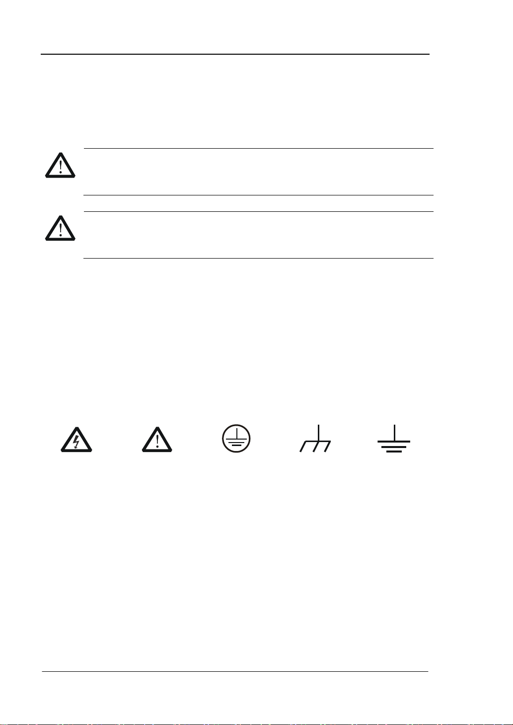
WARNING
Warning statements indicate the conditions or practices that could result in
injures or loss of life.
CAUTION
Caution statements indicate the conditions or practices that could result in
damage to this product or other property.
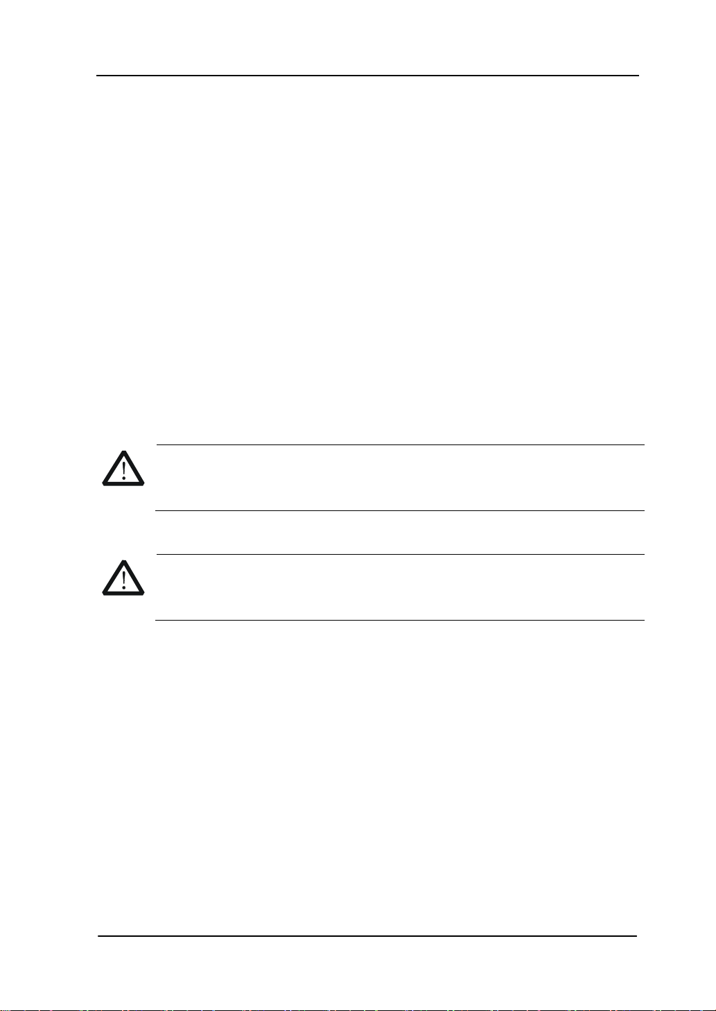
Hazardous
Voltage
Refer to
Instructions
Protective
Earth
Terminal
Chassis
Ground
Test
Ground
Safety Terms and Symbols
Terms in this Manual. These terms may appear in this manual:
Terms on the Product. These terms may appear on the product:
DANGER indicates an injury or hazard may immediately happen.
WARNING indicates an injury or hazard may be accessible potentially.
CAUTION indicates a potential damage to the instrument or other property might
occur.
Symbols on the Product. These symbols may appear on the product:
Quick Guide for DG5000
Page 7
RIGOL
V
CAUTION
To avoid damages to the instrument, do not expose them to liquids which
have causticity.
WARNING
To avoid injury resulting from short circuit, make sure the instrument is
completely dry before reconnecting into a power source.
General Care and Cleaning
General Care
Do not leave or store the instrument exposed to direct sunlight for long periods of
time.
Cleaning
Clean the instrument regularly according to its operating conditions. To clean the
exterior surface, perform the following steps:
1. Disconnect the instrument from all power sources.
2. Clean the loose dust on the outside of the instrument with a lint- free cloth (with
a mild detergent and water). When clean the LCD, take care to avoid scarifying
it.
Quick Guide for DG5000
Page 8

RIGOL
VI
Environmental Considerations
The following symbol indicates that this product complies with the applicable
European Union requirements according to Directives 2002/96/EC on waste electrical
and electronic equipment (WEEE) and batteries.
Product End-of-Life Handling
The equipment may contain substances that could be harmful to the environment or
human health. In order to avoid release of such substances into the environment and
harmful to human health, we encourage you to recycle this product in an appropriate
system that will ensure that most of the materials are reused or recycled
appropriately. Please contact your local authorities for disposal or recycling
information.
Quick Guide for DG5000
Page 9

RIGOL
VII
Content
Guaranty and Declaration ......................................................................... I
Safety Requirement ................................................................................ II
General Safety Summary ........................................................................... II
Safety Terms and Symbols ....................................................................... IV
General Care and Cleaning ........................................................................ V
Environmental Considerations ................................................................... VI
Quick Start ............................................................................................... 1
General Inspection ................................................................................... 1
Handle Adjustment ................................................................................... 2
Appearance and Dimensions ...................................................................... 3
Front Panel .............................................................................................. 4
Rear Panel .............................................................................................. 10
Power on the Generator ........................................................................... 13
User Interface ......................................................................................... 14
Parameter Mode ............................................................................... 14
Graph Mode ..................................................................................... 14
To Rack Mount the Instrument .................................................................. 16
Kit Parts List ........................................................................................... 16
Installation Tool ................................................................................ 17
Space Requirements for Installation .................................................... 18
Installation Procedures ...................................................................... 19
To Use the Security Lock .......................................................................... 22
To Use the Built-In Help ........................................................................... 23
Troubleshooting ..................................................................................... 24
Quick Guide for DG5000
Page 10

Page 11

1
Quick Start
General Inspection
1. Inspect the shipping container for damage.
If there are damages in the container or foam, keep them until the whole
machine and the accessories passing the electrical and mechanical tests.
If your instrument has damaged during shipping, please contact your shipper
and carrier for compensation. RIGOL will provide no free repair or replacement.
2. Inspect the instrument.
In case of any mechanical damage or defect, or if the instrument does not
operate properly or pass the electrical and mechanical tests, please contact your
RIGOL sales representative.
3. Check the accessories
Please check the accessories according to the packing lists. If the accessories are
incomplete or damaged, please contact your RIGOL sales representative.
RIGOL
Quick Guide for DG5000
Page 12

RIGOL
2
Handle Adjustment
To adjust the handle position of the instrument, please grip the handle by sides and
pull it outward. Then, rotate the handle to the desired position. The operating
method is shown below.
Adjusting the handle
Viewing Positions Carrying Position
Quick Guide for DG5000
Page 13

3
Appearance and Dimensions
RIGOL
Front Elevation Unit: mm
Side Elevation Unit: mm
Quick Guide for DG5000
Page 14

RIGOL
4
13.Menu Softkey
12.Page Up/Down
21.Direction Keys
22.Numeric Keyboard
24.CH1 Output Control
25.CH2 Output Control
27.CH2 Output
26.CH1 Output
23.Channel Toggle
1.Power Key
2.USB Host
3.LCD
4.Display Switch 14.Modulation
15.Sweep
16.Burst
20.Knob
17.Store/Recall
18.Utility
19.Help
5.Sine
6.Square
7.Ramp
8.Pulse
9.Noise
10.Arb
11.User-defined Key
Front Panel
The manual illustrates the front panel of the instrument taking the dual-channel
model for example.
Figure 7 Dual-Channel Model Front Panel Overview
Figure 8 Single-Channel Model Front Panel Overview
Quick Guide for DG5000
Page 15

5
1. Power Key
The power soft key is used to turn the generator on or off.
2. USB Host
Support FAT file format USB flash device, RIGOL TMC digital oscilloscope (DS)
and power amplifier (PA).
USB flash device: Read the waveform or state files from the USB flash device,
or store the current instrument state and edited waveform data into the USB
flash device.
TMC DS: Seamlessly interconnect with the RIGOL DS that fits the TMC
standard, read and store the waveform data sampled by the DS and display
it nondestructively.
PA (optional): Support the RIGOL power amplifier, for example, PA1011.
Enable to be configured online and amplify the signal power before output.
3. LCD
480 × 272 TFT color LCD is used to display the current function menu and
parameters setting, system state and prompt messages.
4. Display Switch
For dual-channel model: Switch between Parameter/Graph display mode.
For single-channel model: not available.
5. Sine
Generate a Sine waveform with frequency from 1 μHz to 350 MHz.
When the function is enabled, the backlight of the button turns on.
Enable to change Frequency/Period, Amplitude/High Level, Offset/Low Level
and Start Phase of the Sine waveform.
6. Square
Generate a Square waveform with frequency from 1 μHz to 120 MHz and variable
duty cycle.
When the function is enabled, the backlight of the button turns on.
Enable to change Frequency/Period, Amplitude/High Level, Offset/Low Level,
Duty Cycle and Start Phase of the Square waveform.
7. Ramp
Generate a Ramp waveform with frequency from 1 μHz to 5 MHz and variable
symmetry.
When the function is enabled, the backlight of the button turns on.
RIGOL
Quick Guide for DG5000
Page 16

RIGOL
6
Enable to change Frequency/Period, Amplitude/High Level, Offset/Low Level,
Symmetry and Start Phase of the Ramp waveform.
8. Pulse
Generate a Pulse waveform with frequency from 1 μHz to 50 MHz and variable
pulse width and edge time.
When the function is enabled, the backlight of the button turns on.
Enable to change Frequency/Period, Amplitude/High Level, Offset/Low Level,
Pulse Width/Duty Cycle, Leading Edge Time, Trailing Edge Time and Delay
of the Pulse waveform.
9. Noise
Generate a Gauss Noise with bandwidth up to 250 MHz.
When the function is enabled, the backlight of the button turns on.
Enable to change Amplitude/High Level and Offset/Low Level of the Noise
waveform.
10. Arb
Generate an arbitrary waveform with frequency from 1 μHz to 50 MHz.
Provide two output modes: “Normal” and “Play”.
Generate 10 built-in waveforms: DC, Sinc, Exponential Rise, Exponential Fall,
ECG, Gauss, Haversine, Lorentz, Pulse and Dual-Tone; generate arbitrary
waveforms from USB flash device; generate arbitrary waveforms edited
online (512 kpts) or through PC software and then downloaded to the
instrument by the users; support wavetable points up to 128 Mpts.
When the function is enabled, the backlight of the button turns on.
Enable to change Frequency/Period, Amplitude/High Level, Offset/Low Level
and Start Phase of the arbitrary waveform.
11. User-defined Key
For some frequently used menus with “deep” location, users can define them as
shortcuts (under the function key Utility). And then, in any operation interface,
press the User-defined Key to quickly open and set your desired menu or
function.
12. Page Up/Down
Open the previous or next page of the current function menu.
13. Menu Softkey
Press any softkey to activate the corresponding menu.
Quick Guide for DG5000
Page 17

7
14. Modulation
Generate modulated waveforms. Provide versatile common modulations and
user defined IQ modulation.
Common Modulations: Support internal and external modulations, generate
AM, FM, PM, ASK, FSK, PSK and PWM modulated signal.
User Defined IQ Modulation: Support internal and external modulation,
generate IQ modulated signal.
15. Sweep
Generate the frequency sweeping signal of Sine, Square, Ramp and Arbitrary
Waveforms (except DC).
Support three sweep types: Linear, Log and Step.
Set Start Hold, End Hold and Return Time.
Provide the “Mark” function.
When the function is enabled, the backlight of the button turns on.
16. Burst
Generate burst waveforms of Sine, Square, Ramp, Pulse and Arbitrary waveform
(except DC).
Support three burst types: N Cycle, Infinite and Gated.
Noise can also be used to generate Gated burst.
When the function is enabled, the backlight of the button turns on.
In remote mode, press this button to switch to local mode.
17. Store/Recall
Store/recall the instrument state or user-defined arbitrary waveform data.
Support file management system to execute normal file operations.
Provide 1 GBytes built-in non-volatile memory (C Disk) and two external USB
flash devices (D Disk and E Disk). In addition, files stored in a USB flash
device can be copied to C Disk for long-term preservation.
When the function is enabled, the backlight of the button turns on.
18. Utility
Provide some advanced operations, including system parameters setting,
waveform saving and printing, functions expanding and the remote control
interfaces configuration.
When the function is enabled, the backlight of the button turns on.
19. Help
To get context help information about any front-panel key or menu softkey, press
RIGOL
Quick Guide for DG5000
Page 18

RIGOL
8
this key until it is illuminated and then press the desired key.
20. Knob
Be used to increase (clockwise) or decrease (anticlockwise) the current
highlighted number. Also can be used to select file location or switch the
character of the soft keyboard when entering file name.
21. Direction Keys
Be used to switch the digits of the number, the data page and the file locations.
22. Numeric Keyboard
Consists of numbers (0~9), decimal point (.) and operators (+/-). Notice that, if
a negative required, please input an operator “-” before the numbers. In addition,
the decimal point “.” also can be used to switch units quickly.
23. Channel Toggle
For dual-channel model: switch and toggle a channel.
For single-channel model: not available.
24. CH1 Output Control
For dual-channel model: control the output of CH1. When the output function
enables, the backlight of the button goes on.
For single-channel model: trigger “Sweep” and “Burst” manually.
25. CH2 Output Control
For dual-channel model: control the output of CH2. When the output function
enables, the backlight of the button turns on.
For single-channel model: control the output of the main channel. When the
output function enables, the backlight of the button turns on.
26. CH1 Output
This BNC connector is used as an output terminal.
For dual-channel model: enable or disable waveform signals generated from
[Output] connector corresponding to CH1. The nominal output impedance is 50
Ω.
For single-channel model: output a TTL-compatible pulse synchronized with the
main output. The nominal source impedance is 50 Ω.
27. CH2 Output
This BNC connector is used as an output terminal. The nominal output
Quick Guide for DG5000
Page 19

9
impedance is 50 Ω.
CAUTION
Overvoltage protection of the output channel will take effect once any of
the following conditions is met.
Amplitude setting in the generator is greater than 2 Vpp; the input
voltage is greater than ± 12.1 V (± 0.1 V) and frequency is lower than
10 kHz.
Amplitude setting in the generator is lower than or equal to 2 Vpp; the
input voltage is greater than ± 4.8 V (± 0.1 V) and frequency is lower
than 10 kHz.
The message “OverLoad protect, The output is off!” will appear on the
screen when overvoltage protection takes effect.
For dual-channel model: enable or disable waveform signals generated from
[Output] connector corresponding to CH2.
For single-channel model: output signals of the main channel.
RIGOL
Quick Guide for DG5000
Page 20

RIGOL
10
1.Digital Output
2.CH1 Mod/I Signal In
3.CH2 Mod/I Signal In
4.CH1 Q Signal In
5.CH2 Q Signal In
6.CH1 Sync Out
7.CH2 Sync Out
8.CH1 ExtTrig In
9.CH2 ExtTrig In
10.10MHz In
11.10MHz Out
12.LAN
13.USB Device
14.GPIB
15.USB Host
16.Lock Hole
17.Power Switch
18.Power Socket
Rear Panel
The manual illustrates the rear panel of the instrument taking the dual-channel
model for example.
Figure 9 Dual-Channel Model Rear Panel Overview
Figure 10 Single-Channel Model Rear Panel Overview
Quick Guide for DG5000
Page 21

11
1. DIGITAL OUTPUT
Connect the generator with the “logic signal output module” DG-POD-A
(optional). Then, configure specific sequence digital signal in the generator and
output the signal through the digital module.
2. CH1 Mod/I Signal In (Mod/I1)
This SMB connector accepts an external Analog modulation signal or In-Phase (I)
baseband signal to be used in CH1’s modulation. The nominal input impedance
is 10 kΩ.
3. CH2 Mod/I Signal In (Mod/I2)
This SMB connector accepts an external Analog modulation signal or In-Phase (I)
baseband signal to be used in CH2’s modulation. The nominal input impedance
is 10 kΩ.
4. CH1 Q Signal In (Q1)
This SMB connector accepts an external Analog/ Quadrature Phase (Q)
modulation signal to be used in CH1’s modulation. The nominal input impedance
is 10 kΩ.
5. CH2 Q Signal In (Q2)
This SMB connector accepts an external Analog/ Quadrature Phase (Q)
modulation signal to be used in CH2’s modulation. The nominal input impedance
is 10 kΩ.
6. CH1 Sync Out (Sync1)
This SMB connector outputs a TTL-compatible pulse synchronized with the
output of CH1. The nominal source impedance is 50 Ω.
7. CH2 Sync Out (Sync2)
This SMB connector outputs a TTL-compatible pulse synchronized with the
output of CH2. The nominal source impedance is 50 Ω.
8. CH1 ExtTrig In (ExtTrig1)
This SMB connector accepts an external TTL-compatible pulse as the trigger
input of CH1. Besides, it can also be used as the trigger out in Sweep and Burst
mode.
RIGOL
Quick Guide for DG5000
Page 22

RIGOL
12
9. CH2 ExtTrig In (ExtTrig2)
This SMB connector accepts an external TTL-compatible pulse as the trigger
input of CH2. Besides, it can also be used as the trigger out in Sweep and Burst
mode.
10. (11.)10MHz In/10MHz Out
These two connectors are used to synchronize generators. The connector
[10MHz In] accepts an external 10 MHz clock signal, and the connector [10MHz
Out] can output a 10 MHz clock signal generated by the crystal inside the
generator.
19. LAN
Through this interface, the generator can be connected to your local network for
remote control. An integrated testing system may be built, as the generator
conforms to the LXI-C class standard of LAN-based instrument control.
20. USB Device
Through this interface, the generator can be connected to a PictBridge printer to
print its screen, or be connected to a PC and controlled via PC software.
21. GPIB
Meet IEEE-488.2 specification.
22. USB Host
Reference to “USB Host” page 5.
23. Lock Hole
Use the security lock (please buy it yourself) to lock the generator in fixed
location.
24. Power Switch
Connect or cut off the power supply.
25. Power Socket
The generator can accept two types of AC power supply.
AC Power Supply: 45-440 Hz, 100-127 V, or 45-60 Hz, 100-240 V.
Power Fuse: 250 V, T3A.
Power Consumption: less than 125 W.
Quick Guide for DG5000
Page 23

RIGOL
13
WARNING
To avoid electric shock, make sure the instrument has been properly
grounded.
Power on the Generator
Connect the generator to the AC supply by using the supplied power cord, and then
perform the following steps.
1. Turn on the power of the instrument
Turn on the power switch at the rear panel of the instrument.
2. Start-up the instrument
Press down the power key at the front panel. The instrument starts and
executes self-test and then enters the user interface.
Quick Guide for DG5000
Page 24

RIGOL
14
2.Current
Function
1.Status
Bar
8.Menu Softkey
7.Output Cfg
6.Wave Disp
4.Freq Disp
3.Channel Label
5.Ampl Disp
User Interface
The user interface is usually shown in two modes which are “Parameter” and
“Graphic”. The illustration given here will take the “Graphic” mode of the
Dual-Channel Model for example.
Parameter Mode
Figure 11 User Interface (Parameter Mode)
Graph Mode
In parameter mode, toggle the “Display Switch” at the upper right of the screen
to switch to the Graphic Mode.
Figure 12 User Interface (Graphic Mode)
Quick Guide for DG5000
Page 25

15
1. Status Bar
Indicate system status. For example, an icon denotes that a USB flash
device has been detected.
2. Current Function
Show the current active function. For example, “Sine” denotes that sine wave has
been selected at present.
3. Channel Label Bar
Be divided into two parts which marks the display areas of CH1 and CH2
respectively. The currently selected channel label will be highlighted.
4. Frequency Display
Display the current waveform frequency in each channel. Press corresponding
softkey Freq and use the numeric keyboard or knob to modify this parameter.
The parameter that can be modified currently will be highlighted.
5. Amplitude Display
Display the current waveform amplitude in each channel. Press corresponding
softkey Ampl and use the numeric keyboard or knob to modify this parameter.
The value that can be modified currently will be highlighted.
6. Waveform Display
Display the currently selected waveform shape in each channel. The waveform of
the currently selected channel will be highlighted.
7. Output Configuration
Display the current output configuration in each channel, including “Output
resistance” and “Attenuation setting”.
8. Menu Softkey
Press any softkey to activate the corresponding function.
RIGOL
Quick Guide for DG5000
Page 26

RIGOL
16
NO.
Name
Qty.
Part Number
Description
1-1
Front Panel
1
RM-DG-5-01
1-2
Support Board
1
RM-DG-5-02
1-3
Left Plate
1
RM-DG-5-03
1-4
Right Plate
1
RM-DG-5-04
1-5
Fixed Figure
2
RM-DG-5-05
2-1
M4 Screw
19
RM-SCREW-01
M4*6 Phil-Slot Pan Head Machine Screw Nail
2-2
M6 Screw
4
RM-SCREW-02
M6*20 Phil-Slot Pan Head Machine Screw Nail
2-3
M6 Nut
4
RM-SCREW-03
M6*4 Square Machine Female Screw Contain
Lock Blade
To Rack Mount the Instrument
This generator can be mounted in a standard 19-inch rack cabinet. Please
disassemble the cushioning material and handle before the installation.
Kit Parts List
Quick Guide for DG5000
Page 27

RIGOL
17
2-1 2-2 2-3
Installation Tool
PH2 Phillips Screwdriver (recommended).
Quick Guide for DG5000
Page 28

RIGOL
18
Space Requirements for Installation
The following requirements must be fulfilled by the machine cabinet in which the
instrument is mounted.
Dimension of the machine cabinet must be standard 19-inch.
At least 3U (133.5 mm) space should be provided by the machine cabinet.
The depth inside the machine cabinet should not be less than 530 mm.
The dimension of the instrument after being mounted is shown below.
Quick Guide for DG5000
Page 29

RIGOL
19
Installation Procedures
Only authorized operators can execute the installation operation. The instrument will
be damaged or installed in rack incorrectly if the installation is not proper.
1. Remove the handle: please grip the handle by sides, pull it outward and then
upward.
2. Install the right and left plates: align the detents of right and left plates with the
openings on the support board and insert them into the support board
respectively, then fix them with eight M4 screws.
Quick Guide for DG5000
Page 30

RIGOL
20
3. Place the instrument: align the protection pads of the instrument with the
corresponding holes and then place it on the Support Board.
4. Fixed the instrument: Fasten the instrument tightly on the Support Board with
two Fixed Figures and fixed it with four M4 screws.
Quick Guide for DG5000
Page 31

RIGOL
21
5. Install the Front Panel: aiming the instrument front panel at the opening of the
Front Panel of the machine rack and fix them with four M4 screws.
6. Load into the machine cabinet: mount the rack fixed with instrument into a
standard 19-inch machine cabinet with four M6 screws and square nuts.
7. Post-installation notice: The rack occupies a height of 3U. The holes pointed out
by the arrows are the installation holes. Note that they are aligned while
installing.
Quick Guide for DG5000
Page 32

RIGOL
22
To Use the Security Lock
Use a security lock to lock your generator in a desired location. As shown in the
picture below, align the lock with the lock hole on the generator and insert the lock.
Turn the key clockwise to lock the instrument and then pull the key out.
Quick Guide for DG5000
Page 33

RIGOL
23
To Use the Built-In Help
To get context help information about any front-panel key or menu softkey, press
Help to illuminate the key and then press the desired key to get corresponding help.
Pressing Help twice will get the following common help.
1. View the last displayed message.
2. View error queue of the remote commands.
3. Get the help information of a key.
4. Generate a basic waveform.
5. Generate an arbitrary waveform.
6. Generate a modulated waveform.
7. Generate a frequency Sweep.
8. Generate a Burst waveform.
9. IQ (In-Phase/Quadrature) modulation.
10. Frequency hopping output.
11. Storage management.
12. Synchronize multiple Generators.
13. Seamlessly connected with the RIGOL DS.
14. Get technical support from RIGOL.
Quick Guide for DG5000
Page 34

RIGOL
24
Troubleshooting
This chapter lists the commonly encountered failures and their solutions. When you
encounter those problems, please solve them following the corresponding steps. If
the problem persists, please contact RIGOL and provide your device information
(Utility System Sys Info).
1. The screen is still dark (no display) after power on:
(1) Check if the power is correctly connected.
(2) Check if the power switch is really on.
(3) Restart the instrument after finishing the above inspections.
(4) If it does not work correctly, contact RIGOL for our service.
2. The settings are correct but no waveform is generated:
(1) Check if the Signal Line is correctly connected to the Output terminal.
(2) Check if the BNC can work correctly.
(3) Check the Output button, if it is turned on.
(4) Set Power On as “Last” and then restart the instrument after finishing the
above inspections.
(5) If it does not work correctly, contact RIGOL for our service.
3. The U-disk cannot be recognized:
(1) Check if the U-disk can work normally.
(2) Make sure the U-disk is USB flash disk. The generator doesn’t support hard
drive-based U-disk.
(3) Restart the instrument, reinsert the USB device and check it.
(4) If the U-disk still does not work normally, please contact RIGOL.
Quick Guide for DG5000
 Loading...