


RIGOL
Quick Guide
DG4000 Series
Function/Arbitrary Waveform Generator
Feb. 2014
RIGOL Technologies, Inc.


RIGOL
Guaranty and Declaration
Copyright
© 2011 RIGOL Technologies, Inc. All R ights Reser v ed.
Trademark Information
RIGOL is a registered trademark of RIGOL Technologies, Inc.
Publication Number
QGB04106-1110
Notices
RIGOL products are protected by patent law in and outside of P.R.C.
RIGOL reserves the right to modify or change parts of or all the specifications
and pricing policies at company’s sole decision.
Information in this publication replaces all previously corresponding material.
RIGOL shall not be liable for losses caused by either in cidental or c onsequential
in connection with the fu r nis hing , use or perfo rman ce of this manual as well as
any information contained.
Any part of this document is forbidden to cop y or photocopy or rearrange
without prior written approval of RIGOL.
Product Certification
RIGOL guar antees this pr oduct confo rms to the national and industrial stan dar ds in
China as well as the ISO9001:2008 standard and the ISO14001:2004 standard.
Other international standard conformance certification is in progress.
Contact Us
If you have any problem or requirement when using our products or this manual,
please contact RIGOL.
E-mail: service@rigol.com
Websites: www.rigol.com
Quick Guide for DG4000
I

RIGOL
Safety Requirement
General Safety Summary
Please review the following safety precautions carefully before putting the
instrument into operation so as to avoid any personal injuries or damages to the
instrument and any product connecte d to it. To prev ent potential hazards, plea se use
the instrument only specified by this manual.
Use Proper Power Cord.
Only the power cord designed for the instrument and authorized for use within the
local country could be used.
Ground The Instrument.
The instrument is grounded through the Protective Earth lead of the power cord. To
avoid electric shock, it is e ssential t o connect the ea rth terminal of power cord to the
Protective Earth terminal before any inputs or outputs.
Connect the Probe Correctly.
If a probe is used, do not connect the ground lead to high voltage since it has the
isobaric electric potential as ground.
Observe All Terminal Ratings.
To avoid fire or shock hazard, observe all ratings an d markers on the instrume nt and
check your manual for more info rmatio n a bout r ati ngs before connecting.
Use Proper Overvoltage Protection.
Make sure that no overvoltage (such as that caused by a thunderstorm) can reach
the product, or else the operator might expose to danger of electrical shock.
Do Not Operate Without C o ve r s.
Do not operate the instrument with covers or panels removed.
Do Not Insert Anything into the Holes of Fan.
Do not insert anything into the holes of the fan to avoid damaging the instrument.
II
Quick Guide for DG4000

RIGOL
Use Proper Fuse.
Please use the specified fuse.
Avoid Circuit or Wire Exposure.
Do not touch exposed junctions and components when the unit is powered.
Do Not Operate With Suspected Failures.
If you suspect damage occurs to the instrument, have it inspected by qualified
service personnel before further operations. Any maintenance, adjustment or
replacement especially to circuits or accessories must be performed by RIGOL
authorized personnel.
Keep Well Ventilation.
Inadequate ventilation may cause increasing of temperature or damages to the
device. So please keep well ventilated and inspect the intake and fan regularly.
Do Not Operate in Wet Conditions.
In order to av oid short circuiting t o the interi or of the device or electric shock, please
do not operate in a humid environment.
Do Not Operate in an Explosive Atmosphere.
In order to avoid damages to the device or personal injuries, it is important to
operat e the device away from an explosive atmospher e.
Keep Product Surfaces Clean and Dry.
To avoid the influence of dust and/or moisture in air, please keep the surface of
device clean and dry.
Electrostatic Prevention.
Operate in an electrostatic discharge protective area environment to avoid damages
induced by static discharges. Always ground both the internal and external
conductors of the cable to release static before connecting.
Proper Use of Battery.
If a battery is supplied, it must not be exposed to high temperature or in contact with
fire. Keep it out of the reach of children. Improper change of battery (note: lithium
battery) may cause explosion. Use RIGOL specified battery only.
Quick Guide for DG4000
III

RIGOL
Handling Safety.
Please handle with care during transportation to avoid damages to buttons, knob
interfaces and other parts on the panels.
IV
Quick Guide for DG4000
RIGOL
Warning state ments indicate the conditions or practices that could result i n
Hazardous
Safety
Protective
Chassis
Test
Safety Terms and Symbols
Terms Used in this Manual. These terms may appear in this manual:
WARNING
injury or loss of life.
CAUTION
Caution statements indicate the c onditions or practic es that coul d result i n
damage to this product or other property.
Terms Used on the Product. These terms may appear on the Product:
DANGER indicates an injury or hazard may immediately happen.
WARNING indicates an injury or hazard may be accessible potentially.
CAUTION indicates potential damage to the instrument or other property might
occur.
Symbols Used on the Product. These symbols may appear on the product:
Voltage
Warning
Earth
Terminal
Ground
Quick Guide for DG4000
Ground
V

RIGOL
Allgemeine Sicherheits Informationen
Überprüfen Sie diefolgenden Sicherheitshinweise
sorgfältigumPersonenschädenoderSchäden am Gerätundan damit verbundenen
weiteren Gerätenzu vermeiden. Zur Vermeidung vonGefa hren, nutzen Sie bitte das
Gerät nur so, wiein diesem Handbuchangegeben.
Um Feuer oder Verletzungen zu vermeiden, verwenden Sie ein
ordnungsgemäßes Netzkabel.
Verwenden Sie für dieses Gerät nur das für ihr Land zugelass ene u nd genehm igte
Netzkabel.
Erden des Gerätes.
Das Gerät ist durch den Schutzleiter im Netzkabel geerdet. Um Gefahren durch
elektrischen Schlag zu vermeiden , ist es unerlässlich, die Er dung durchzufüh ren. Erst
dann dürfen weitere Ein- oder Aus gä nge verbunde n werden.
Anschluss einesTastkopfes.
Die Erdungsklemmen der Sonden sindauf dem gleichen Spannungspegel des
Instruments geerdet. SchließenSie die Erdungsklemmen an keine hohe Spannung
an.
Beachten Sie alle Anschlüsse.
Zur Vermeidung von Feuer oder Stromschlag, beachten Sie alle Bemerkungen und
Markierungen auf dem Instrument. Bef olgen Sie die Bedienun gsanleitung für weitere
Informationen, bevor Sie weitere Anschlüsse an das Instrument legen.
Verwenden Sie einen geeigneten Überspannungsschutz.
Stellen Sie sicher, daß keinerlei Überspannung (wie z.B. durch Gewitt er ver urs acht)
das Gerät erreichen kann. Andernfallsbestehtfür de n Anwender die
GefahreinesStromschlages.
Nicht ohne Abdeckung einschalten.
Betreiben Sie das Gerät nicht mit entfernten Gehäuse-Abdeckungen.
Betreiben Sie das Gerät nicht geöffnet.
Der Betrieb mit offenen oder entfernten Gehäuseteilen ist nicht zulässig. Nichts in
entsprechende Öffnungen stecken (Lüfter z.B.)
Passende Sicherung verwenden.
Setzen Sie nur die spezifikationsgemäßen Sicherungen ein.
VI
Quick Guide for DG4000

RIGOL
Vermeiden Sie ungeschützte Verbindungen.
Berühren Sie keine unisolierten Verbindungen oder Baugruppen, während das Gerät
in Betrieb ist.
Betreiben Sie das Gerät n ic h t i m Fehlerfall.
Wenn Sie am Gerät einen Defekt vermuten, sorgen Sie dafür, bevor Sie das Gerät
wieder betreiben, dass eine Untersuchu ng durch qual ifiziertes Kundendienstpersonal
durchgeführt wird.Jedwede Wartung, Einstellarbeiten oder Austausch von Teilen am
Gerät, sowie am Zubehör dürfen nur von RIGOL a utorisiertem Personal
durchgeführt werden.
Belüftung sicherstellen.
Unzureichende Belüftung kann zu Temperaturanstiegen und somit zu thermischen
Schäden am Gerät führen. Stellen Sie deswegen die Belüftung sicher und
kontrollieren regelmäßig Lüfter und Belüftungsöffnungen.
Nicht in feuc h te r Um g ebung betre i be n .
Zur Vermeidun g von Kurzschluß im Geräteinne ren und Stromschlag betreiben Sie das
Gerät bitte niemals in feuchter Umgebung.
Nicht in explosiver Atmosphäre betreiben.
Zur Ve rm e idung von P e rsonen- und Sachschäden ist es unumgänglich, das Gerät
ausschließlich fernab jedweder explosiven At mosphäre zu betreiben.
Geräteoberflächen sauber und trocken halten.
Um den Einfluß von Staub und Feuchtigkeit aus der Luft auszuschließen, halten Sie
bitte die Geräteoberflächen sauber und trocken.
Schutz gegen elektrostatische Entladung (ESD).
Sorgen Sie für eine elektrostatisch geschützte Umgebung, um somit Sc h äden und
Funktionsstörungen durch ESD zu vermeiden. Erden Sie vor dem Anschluß immer
Innen- und Außenleiter der V erbindungsleitung, um st atische Aufladung zu entladen.
Die richtige Verwendung desAkku.
Wenneine Batterieverwendet wird, vermeiden Sie hohe Temperaturen bzw. Feuer
ausgesetzt werden.Bewahren Sie es außerhalbder Reichweitevon Kindern
auf . UnsachgemäßeÄnderung derBatterie(Anmerkun g:Lithiu m-Batterie)kann zu einer
Explosion führen. VerwendenSie nur von RIGOLangegebenenAkkus.
Sicherer Transport.
Transportieren Sie das Gerät sorgfältig (Verpackung!), um Schäden an
Bedienelementen, Anschlüssen und anderen Teilen zu vermeiden.
Quick Guide for DG4000
VII
RIGOL
WARNING
CAUTION
DANGER
weist auf eine Verletzung ode r Gefäh r dun g hin, die sof ort
WARNING
Sicherheits Begriffe und Symbole
Begriffe in diesem Guide. Diese Begriffe können in diesem Handbuch
auftauchen:
Die Kennzeichnung WARNING beschreibt Gefahrenq uelle n die leibliche
Schäden oder den Tod von Personen zur Folge haben können.
Die Kennzeichnung Caution (Vorsicht) beschreibt Gefahrenquellen die
Schäden am Gerät hervorrufen können.
Begriffe auf dem Produkt. Diese Bedingungen können auf dem Produkt
erscheinen:
geschehen kann.
weist auf eine Verletzung oder Gefäh rdung hin, die möglicherweise
nicht sofort geschehen.
CAUTION bedeutet, dass eine mö gliche Beschädig ung des Instruments oder
anderer Gegenstände auftreten kann.
Symbole auf dem Produkt. Diese Symbole können auf dem Produkt
erscheinen:
GefährlicheS
pannung
SicherheitsHinweis
Schutz-erde Gehäusemasse Erde
VIII
Quick Guide for DG4000
RIGOL
To avoid damages to the instrument, do not expose them to liquids which
General Care and Cleaning
General Care
Do not leave or store the instrument exposed to direct sunlight for long periods of
time.
Cleaning
Clean the instrument regularly according to its operating conditions. To clean the
exterior surface, perform the following steps:
1. Disconnect the instrument from all power sources.
2. Clean the loose dust on t he outside of the ins trument with a lint - free cloth (with
mild detergent or water). When cleaning t h e L C D, ta ke c are t o avoid sc ar ifying
it.
CAUTION
have causticity.
WARNING
To avoid injury resulting from short circuit, make sure the instrument is
completely dry before reconnecting into a power sour ce.
Quick Guide for DG4000
IX

RIGOL
Environmental Consideratio ns
The following symbol indicates that this product complies with the WEEE Directives
2002/96/EC.
Product End-of-Life Handling
The equipment may contain substances that could be ha rmful to the environ ment o r
human health. In order to avoid release of such substances into the environment and
harmful to human health, we encourage you to recycle this product in an appropriate
system that will ensure that most of the materials are reused or recycled
appropriately. Please contact your local authorities for disposal or recycling
information.
X
Quick Guide for DG4000

RIGOL
Contents
Guaranty and Declaration ......................................................................... I
Safety Requirement ................................................................................ II
General Safety Summary ........................................................................... II
Safety Terms and Symbols ........................................................................ V
Allgemeine Sicherheits Informationen ........................................................ VI
Sicherheits Begriffe und Symbole ............................................................ VIII
General Care and Cleaning ....................................................................... IX
Environmental Considerations .................................................................... X
Quick Start ............................................................................................... 1
General Inspection ................................................................................... 2
To Adjust the Supporting Legs ................................................................... 3
Appearance and Dim e nsions ...................................................................... 4
Front Panel .............................................................................................. 6
Rear Panel .............................................................................................. 13
To Connect to Power ................................................................................ 16
To Replace the Fuse ................................................................................ 17
User Interface ......................................................................................... 18
Parameter Setting Method ........................................................................ 21
Numeric Keyboard............................................................................. 21
Direction keys and Knob .................................................................... 22
To Use the Built-In Help ........................................................................... 23
To Use the Security Lock .......................................................................... 24
To Use the Rack Mount Kit ....................................................................... 25
Kit Parts List ..................................................................................... 25
Installation Tool ................................................................................ 26
Installation Space ............................................................................. 27
Installation Procedure ....................................................................... 30
Troubleshooting ..................................................................................... 34
Quick Guide for DG4000
XI


RIGOL
Quick Start
This chapter introduces the front/rear panel, user interface and parameter setting
method, as well as announcements during first use of the instrument.
Subjects in this chapter:
General Inspection
To Adjust the Supporting Legs
Dimensions
Front Panel
Rear Panel
To Connect to Power
To Replace the Fuse
User Interface
Parameter Setting Method
To Use the Built-In Help
To Use the Security Lock
To Use the Rack Mount Kit
Quick Guide for DG4000
1

RIGOL
General Inspection
1. Inspect the shipping container for damage.
If there are damages in the container or foam, keep them until the whole
machine and the accessories pass the electrical and mechanical tests.
If your instrument has damaged during shipping, please contact your shipper
and carrier f or co mpensation . RIGOL will provide no free repai r or replacem ent.
2. Inspect the instrument.
In case of any mechanical damage or defect, or if the instrument does not
operate properly or pass the electrical and mechanical tests, contact your local
sales representative of RIGOL.
3. Check the Accessories
If the contents are incomplete or damaged, please contact your local sales
representative of RIGOL.
2
Quick Guide for DG4000

RIGOL
To Adjust the Supporting Legs
DG4000 allows users to unfold the supporting legs as stands to tilt the generator
upwards for easier operation and observation during operation. Users can fold the
supporting legs for easier storage or carry when the instrument is not in use.
Figure 1 Unfold the Supporting Legs
Figure 2 Fold the Supporting Legs
Supporting Legs
Quick Guide for DG4000
3
RIGOL
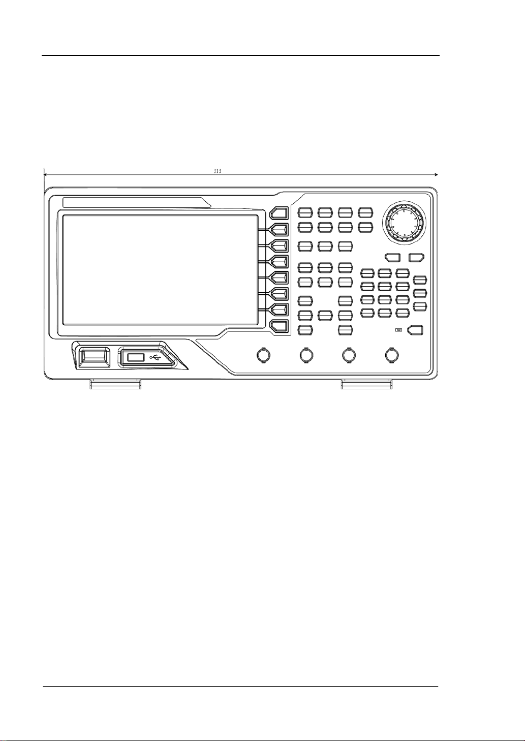
Appearance and Dimensions
The appearance and dimensions of DG4000 are as shown in Figure 3 and Figure 4
and the unit is mm.
Figure 3 Front View
4
Quick Guide for DG4000

RIGOL
Figure 4 Side View
Quick Guide for DG4000
5

RIGOL
1. Power Key
2. USB Host
3. Menu Softkey
4. Page Up/Down
5. CH1 Output
6. CH1 Sync Output
7. CH2 Output
8. CH2 Sync Output
10. Counter
11. Numeric
Keyboard
9. Channels Control
12. Knob
13. Direction
Keys
14. Waveforms
15. Modes
16. Return
17. Shortcuts/Utility
18. LCD
Front Panel
The front panel of DG4000 is shown below.
Figure 5 DG4000 Front Panel
1. Power Key
The power softkey is used to turn the generator on or off. When the power
softkey is turned off, the generator is in standby mode and the generator is in
power-off mode only when the power cable at the rear panel is pulled out.
Users can enable or disable the function of this softkey. When enabled, users
need to press this softkey to start the instrument after power-on; when disabled,
the instrument starts automaticall y aft er powe r-on.
2. USB Host
Support FAT file format USB storage device. Read the waveform or state files
from th e USB storage device, or store the current instrument state and edited
waveform data into the USB storage device, or store the content currently
displayed on the screen in specified picture format (.bmp or .jpeg) in USB
storage device.
6
Quick Guide for DG4000

3. Menu Softkey
Correspond to the left menus respectively. Press any softkey to activate the
corresponding menu.
4. Page Up/Down
Open the previous or next page of the current function menu.
5. CH1 Output
BNC connector with 50Ω nominal output impedance.
When Output1 is enabled (the backlight turns on), this connector outputs
waveform according to the current configuration of CH1.
6. CH1 Sync Output
BNC connector with 50Ω nominal output impedance.
When the sync output of CH1 is enabled, this connector outputs the sync signal
corresponding to the current settings of CH1.
7. CH2 Output
BNC connector with 50Ω nominal output impedance.
When Output2 is enabled (the backlight turns on), this connector outputs
waveform according to t he current configuration of CH2.
8. CH2 Sync Output
BNC connector with 50Ω nominal output impedance.
When the sync output of CH2 is enabled, this connector outputs the sync signal
corresponding to the current settings of CH2.
9. Channels Control
CH1: used to select CH1. When CH1 is selected (the backlight turns on), users
can set the waveform and parameters of CH1.
CH2: used to select CH2. When CH2 is selected (the backlight turns on), users
can set the waveform and parameters of CH2.
Trigger1: in sweep or burst mode, it is used to trigger CH1 to generate a sweep
or burst output manually (only when Output1 is enabled).
RIGOL
Quick Guide for DG4000
7

RIGOL
Trigger2: in sweep or burst mode, it is used to trigger CH2 to generate a sweep
or burst output manually (only when Output2 is enabled).
Output1: enable or disable the output of CH1.
Output2: enable or disable the output of CH2.
CH1
CH2: execute channel copy.
10. Counter
Press Counter to turn the counter on or of f. When the counter is turne d on , the
backlight of the key is illuminated and the left indicator flickers. If the counter
interface is currently displayed, press this key again to disable counter function;
if the screen currently displays interfaces other than the counter interface, p r e ss
this key again to switch to counter interface.
11. Numeric Keyboard
It is used to input pa ramete rs and consists of numbers (0 to 9), decim al point (.),
operators (+/-) and buttons (“Enter”, “Cancel” and “Del”). If a negative is
required, please input an operator “-” before the numbers. In addition, the
decimal point “.” can be used to switch units quickly and the opera tors “+/-” can
be used to switch between uppercase and lowercase (for the use method of the
numeric keyboard, refer to the introduction in Parameter Setting Method).
12. Knob
During parameter setting, it is used to increase (clockwise) or decrease
(counterclockwise) the current highlighted num ber.
It is used to select file storage location or select the file to be recalled when
storing or recalling file.
It is used to switch the character in the soft keyboard when entering filename.
In additional, it is also used to select built-in waveform.
13. Direction Keys
When using the knob and direction keys to set parameters, the direction keys are
used to switch the digits of the num ber.
During filename input, they are used to move the curs or.
8
Quick Guide for DG4000

14. Waveforms
Sine----Sine
Generate a Sine waveform with frequency from 1μHz to 160MHz.
When the function is enabled, the backlight of the button turns on.
Enable to change Frequency/Pe riod, Am plitude/H igh Lev el, Off set/Lo w Level
and Start Phase of the Sine waveform.
Square----Square
Generate a Square waveform with frequency from 1μHz to 50MHz and vari able
duty cycle.
When the function is enabled, the backlight of the button turns on.
Enable to cha nge F requency /Peri od, Ampl itude/Hi gh Lev el, Off set/Lo w Level ,
Duty Cycle and Start Phase of the Square waveform.
Ramp----Ramp
Generate a Ramp waveform with frequency from 1μHz to 4MHz and variable
symmetry.
When the function is enabled, the backlight of the button turns on.
Enable to cha nge F requency /Peri od, Ampl itude/Hi gh Lev el, Off set/Lo w Level ,
Symmetry and Start Phase of the Ramp waveform.
Pulse----Pulse
Generate a Pulse waveform with frequency from 1μHz to 40MHz and variabl e
pulse width and edge time.
When the function is enabled, the backlight of the button turns on.
Enable to cha nge F requency /Peri od, Ampl itude/Hi gh Lev el, Off set/Lo w Level ,
Pulse Width/Duty Cycle, Leading Edge Time, Trailing Edge Time and Delay
of the Pulse waveform.
Noise----Noise
Generate a Gauss Noise with 120MHz bandwidth.
When the function is enabled, the backlight of the button turns on.
Enable to change Amplitude/High Level and Offset/Low Level of the Noise.
Arb----Arbitrary Waveforms
Generate an arbitrary waveform with frequency from 1μHz to 40MHz.
Provide Step-by-Step output mode.
RIGOL
Quick Guide for DG4000
9

RIGOL
Generate 150 built-in waveforms: DC, Sinc, Exponential Rise, Exponential
Fall, ECG, Ga uss, Ha versin e, Lo rentz, Pulse , Dual-T o ne etc.; out put ar bitr ary
waveforms stored in USB storage device.
Generate ar bitr ary wa vef orms (1 6kpts ) edited online or th rough PC softw are
and then downloaded to the instrument by the users.
When the function is enabled, the backlight of the button turns on.
Enable to cha nge F requency /Peri od, Ampl itude/Hi gh Level, Offset/Low Level
and Start Phase of the arbitrary waveform.
Harmonic----Harmonic
Generate harmonics with frequency from 1μHz to 80MHz.
Output up to 16th order of harmonic.
Enable to cha nge F requency /Peri od, Ampl itude/Hi gh Lev el, Off set/Lo w Level
and Start Phase of harmonics.
Users can set the harmonic “Order”, “Type”, “Ampl” and “Phase”.
User----User-defined Waveform Key
Users can define the built-in waveform frequently used as shortcut (Utility
UserKey). And then, in any operation interface, p ress User to quickly open the
desired waveform and set its parameters.
15. Modes
Mod----Modulation
Generate the modulated waveforms. Provide various analog modulation and
digital modulation modes and can generate AM, FM, PM, ASK, FSK, PSK, BPSK,
QPSK, 3FSK, 4FSK, OSK or PWM modulated signal.
Support internal and external modulations.
Sweep----Sweep
Generate the frequency sweeping signal of Sine, Square, Ramp and Arbitrary
Waveforms (except DC).
Support three sweep types: L i n e ar, Log and Step.
Support three trigger sources: Internal, External and Manual.
Provide the “Mark” function.
When the function is enabled, the backlight of the button turns on.
10
Quick Guide for DG4000

Burst----Burst
Generate burst waveforms of Sine, Square, Ramp, Pulse and Arbitrary wa veform
(except DC).
Support three burst types: N Cycle, Infinite and Gated.
Noise can also be used to generate Gated burst.
Support three trigger sources: Internal, External and Manual.
When the function is enabled, the backlight of the button turns on.
Note: when the instrument i s working in remote m ode, press this key to return to
local mode.
16. Return
This key is used to return to the previous menu.
17. Shortcuts/Utility
Print: save the content shown on the screen as image in USB storage device.
Edit: this key is the shortcut of “Arb E dit Wfo rm” and is used to enter the
ArbEdit interface quickly.
Preset: used to return the instrument state to default or user-defined states.
Utility: used to set the pa rameters of system. When this fu nction is enabled, t he
backlight of the button turns on.
Store: store or recall the instrument state or user-def ined arbitrary data.
Support file management system to execute normal file operations.
Provide a built-in non-volatile memory (C Disk) and an externa l US B storage
device (D Disk).
When the function is enabled, the backlight of the button turns on.
Help: to get context help i nfor mation a bout any f ront -panel key or menu softkey,
press this key until it is illuminated and then press the desired key.
18. LCD
800 × 480 TFT color LCD is used to display the current function menu and
parameters setting, system state as well as prompt messages.
RIGOL
Quick Guide for DG4000
11

RIGOL
CAUTION
Overvoltage protection of the output channel will take effect once any of
the following conditions is met.
Amplitude setting in the generator is greater than 4 Vpp; the input
voltage is greater than ±11.25 V (±0.1 V) and frequency is lower
than 10kHz.
Amplitude setting in the generator is lower than or equal to 4 Vpp;
the input voltage is greater than ±4.5 V (±0.1 V) and frequency is
lower than 10kHz.
The message “OverLoad protect, The output is off!” will appear on
the screen when overvoltage protection takes effect.
12
Quick Guide for DG4000
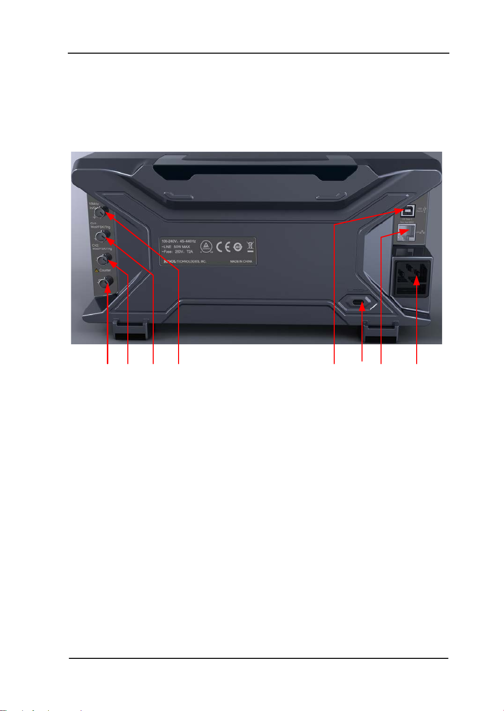
Rear Panel
8. 7. 6. 5. 4. 3. 2. 1.
The rear panel of DG4000 is as shown in the f igure below.
RIGOL
Figure 6 DG4000 Rear Panel
1. AC Power Input
This generator accepts the AC power supply: 100-240V, 45-440Hz.
2. LAN
Connect the generator to the local area n e t w ork for r e mo t e control through thi s
interface. This generator conforms to LXI-C class instrument standards and can
quickly build test system with other devices to easily realize system integration.
3. Security Lock Hole
Users can use the security lock (buy it by themselves) to lock the instrument at a
fixed location.
4. USB Device
PC can be connected through this interface to control the generator remotely
through PC software.
Quick Guide for DG4000
13

RIGOL
5. 10MHz In/Out
BNC female connector with 50Ω nominal impedance. The function of this
connector is determined by the t ype of clo ck used by the generator. DG400 0 can
use internal or external clock.
When internal clock sou rce is used, the connector (used as 10MHz Out) can
output 10MHz clock signal generat ed by the internal cryst al oscillato r o f the
generator.
When external clock source is used, the connector (used as 10MHz In)
accepts a 10MHz external clock signal.
This connector is usually used to synchronize multiple instruments.
6. CH1: Mod/FSK/Trig
BNC female connector with 50Ω nominal impedance. Its function is determined
by the current working mode of CH1.
Mod:
If AM, FM, PM, PWM or OSK is enabled for CH1 and external modulation
source is used, this connector accepts an external modulation signal.
FSK:
If ASK, FSK or PSK is enabled for CH1 and external modulation source is
used, this connector accepts an external modulation signal (users can set
the polarity of the signal).
Trig In:
If CH1 is in sweep or burst mode and external trigger source is used, this
connector accepts an external trigger signal (users can set the polarity of
the signal).
Trig Out:
If CH1 is in sweep or burst mode and internal or manual trigger source is
used, this connector outputs a trigger signal with specified edge.
7. CH2: Mod/FSK/Trig
BNC female connector with 50Ω nominal impedance. Its function is determined
by the current working mode of CH2.
Mod:
If AM, FM, PM, PWM or OSK is enabled for CH2 and external modulation
source is used, this connector accepts an external modulation signal.
14
Quick Guide for DG4000

FSK:
If ASK, FSK or PSK is enabled for CH2 and external modulation source is
used, this connector accepts an external modulation signal (users can set
the polarity of the signal).
Trig In:
If CH2 is in sweep or burst mode and external trigger source is used, this
connector accepts an external trigger signal (users can set the polarity of
the signal).
Trig Out:
If CH2 is in sweep or burst mode and internal or manual trigger source is
used, this connector outputs a trigger signal with specified edge.
8. External Signal Input (Counter)
BNC female connector with 50Ω nominal impedance. It is used to accept an
external signal to be measured by the counter.
RIGOL
Quick Guide for DG4000
15

RIGOL
To Connect to Power
DG4000 accepts the AC power supply: 100V to 240V, 45Hz to 440Hz. Please use the
power cable provided in the accessories to connect the instrument to AC power (as
shown in Figure 7). At this point, the generator is powered on and the powe r but ton
at the lower-left corner of the front panel is in breathing state.
Figure 7 To C on nect to Power
CAUTION
If the power fuse needs to be changed, please retu r n the instru ment back
to our factory and the RIGOL authorized operator will change it for you.
16
Quick Guide for DG4000

RIGOL
To Replace the Fuse
To replace the fuse, please use the specified fuse and follow the steps below.
1. Turn off the instrument, cut off the power supply and remove the power cord.
2. Use a small straight screwdriver to prize out the fuse seat.
3. Take out the fuse seat.
4. Replace the specified fuse.
5. Install the fuse seat again.
Fuse Seat
Fuse
Figure 8 To Replace the Fuse
WARNING
To avoid electric shock, please make sure that the instrument has been
turned o ff a nd the power s u pply has been cut off before re placing the
fuse. Besides, please make sure that the fuse to be installed meets the
requirement.
Quick Guide for DG4000
17

RIGOL
2. Status Bar
1. Current
Function
12. Menu Page Number
3. Channel State4. Channel Configuration
5. Frequency
6. Amplitude
7. Offset
8. Phase
9. Waveform
10. Counter
11. Menu
to LAN successfully, this indicator
When the generator detects connected USB storage device, this
User Interface
DG4000 user interface displays the parameters and waveforms of the two channels
at the same time. The f igure below is the interface when both CH1 and CH2 select
Sine. Different contents will be displayed when different functions are enabled.
Figure 9 User Interface
1. Current Function
Display the name of the function currently selected. For example, “Sine”
indicates that “Sine” waveform function is currently selected and “ArbEdit”
indicates that “Arbitrary Waveform Edit” function is currently selected.
2. Status Bar
The following indicators would be displayed according to the current
configuration.
When the instrument is connected in
will light.
When the generator works in remote mode, this indicator will light.
18
indicator will light.
Quick Guide for DG4000

3. Channel Status
Display areas of CH1 and CH2. Indicate whether the channel is selected and
turned on (ON/OFF).
The area of the channel currently selected is highlighted and the on/off state of
the channel currently turned on is “ON”.
Note:
When a channel is “Selected”, it does not mean that the channel is turned on.
When CH1 is selected, users can configure the parameters of CH1 and the
backlight of CH1 turns on. When CH1 is turned on, CH1 can output waveform
according to the current configuration and the backlight of Output1 turns on.
4. Channel Configurations
Display the current output configuration in each channel, including output
resistance, mode and type of modulating source or trigger source.
Output Resistance
High Impedance: display “HighZ”
Load: display the resistance value, the default is “50Ω”
Mode
Modulation: display “Mod”
Sweep: display “Sweep”
Burst: display “Burst”
Modulating/Trigger Source Type
Internal modulating/trigger: display “Internal”
External modulating/trigger: display “External”
Manual Trigger: display “Manual”
5. Frequency
Display the current waveform frequency in each channel. Press the
corresponding softkey Freq and use the numeric keyboard or direction keys and
knob to modify this para meter. The parameter that can be modified currently will
be highlighted and the lightspot above the number indicates current cursor
location.
6. Amplitude
Display the current waveform amplitude in each channel. Press the
RIGOL
Quick Guide for DG4000
19

RIGOL
corresponding softkey Ampl an d use the numeric ke yboard or direction ke ys and
knob to modify this para meter. The parameter that can be modified currently will
be highlighted and the lightspot above the number indicates current cursor
location.
7. Offset
Display the current wa veform DC offse t in each ch annel. Press the correspondin g
softkey Offset and use the numeric keyboard or direction keys and knob to
modify this parameter. The parameter that can be modified currently will be
highlighted an d the lightspot above t he number in dicates current cursor locatio n.
8. Phase
Display the current waveform phase in each channel. Press the corresponding
softkey Start Phase and use the numeric keyboard or direction keys and knob
to modify this parameter. The parameter that can be modified currently will be
highlighted an d the lightspot above t he number in dicates current cursor locatio n.
9. Waveform
Display the currently selected waveform shape in each channel.
10. Counter
Only available when the counter is turned on and can display the current
measurement state of the counter briefly or in detail.
Brief: only display frequency, period and the number of measurements
performed.
Detail: display the conf igurations of the counter, five measurement values
(Frequency, Period, Duty Cycle, Positive Pulse Width and Negative Pulse
Width) and the number of measurements performed.
11. Menu
Display the operation menu correspondin g to the function currently selected. F or
example, the “Sine” function menu is displayed in the above figure.
12. Menu Page Number
Display the total number of pages and the current page number of the menu,
such as “1 of 1” or “1 of 2”.
20
Quick Guide for DG4000

RIGOL
Parameter Setting Method
Users can use the numeric keyboard or knob and direction keys to set parameters.
Numeric Keyboard
The numeric keyboard consists of:
Number Keys
The 0 to 9 number keys are used to
directly input the desired parameter
value.
Decimal Point
Press this key to insert a decimal poin t “.” at the current position of the cursor.
Operator Key
The operator key “+/-” is used to mod ify the operator of the parameter. Pr ess
this key to set the parameter operator to “-”; press this key again to switch the
operator t o “+”. Note that the operator key is used to switch between uppercase
and lowercase in filename edit.
Enter Key
Press this key to finish parameter input and add the default unit for the
parameter.
Cancel Key
(1) During parameter input, press this key to clear the input in the active
function area and exit parameter input.
(2) Turn the display in the active function area off.
Del Key
(1) During parameter input, press t his key to delete the character at the left of
Quick Guide for DG4000
21

RIGOL
to increase (clockwise) or reduce (counterclockwise)
the cursor.
(2) During filename edit, press this key to delete the characters input.
Direction keys and Knob
Functions of the direction keys:
1. During parameter input, use the direction keys to move the cursor to select the
digit to be edited.
2. D ur ing filename edit, use the direction keys to move the cursor.
Functions of the knob:
When the parameter is in editable state, turn the knob
the parameter with specif ied step.
During filename edit, use the knob to select the char acters in t he soft ke yboar d.
In Arb Select WformBuiltIn, Arb Edit WformSelect Wform and
Utility UserKey, use the knob to sel ec t a rbitrary waveform.
In store and recall, use the knob to select the storage location of the file or to
select the file to be recalled.
22
Quick Guide for DG4000

RIGOL
To Use the Built-In Help
To g et c o n text help information about any front-panel key or menu softkey, press
Help to illuminate the key and then press the desired key to get corresponding help.
Pressing Help twice will get the following common help.
1. View the last displayed message.
2. View error queue of the remote commands.
3. Get the help information of a key.
4. Generate a basic waveform.
5. Generate an arbitrary waveform.
6. Generate a modulated waveform.
7. Generate a frequency Sweep.
8. Generate a Burst waveform.
9. Storage management.
10. Synchronize multiple Generators.
11. Get technical support from RIGOL.
Quick Guide for DG4000
23

RIGOL
To Use the Security Lock
Use the security lock (option) to lock the generator at a fixed location. As shown in
the figure below, align the lock with the lock hole and plug it into the lock hole
vertically, turn the key clockwise to lock the instrument and then pull the key out.
Figure 10 Security Lock Hole
Security Lock Hole
24
Quick Guide for DG4000

To Use the Rack Mount Kit
This instrument can be installed into a standard 19 inches cabinet.
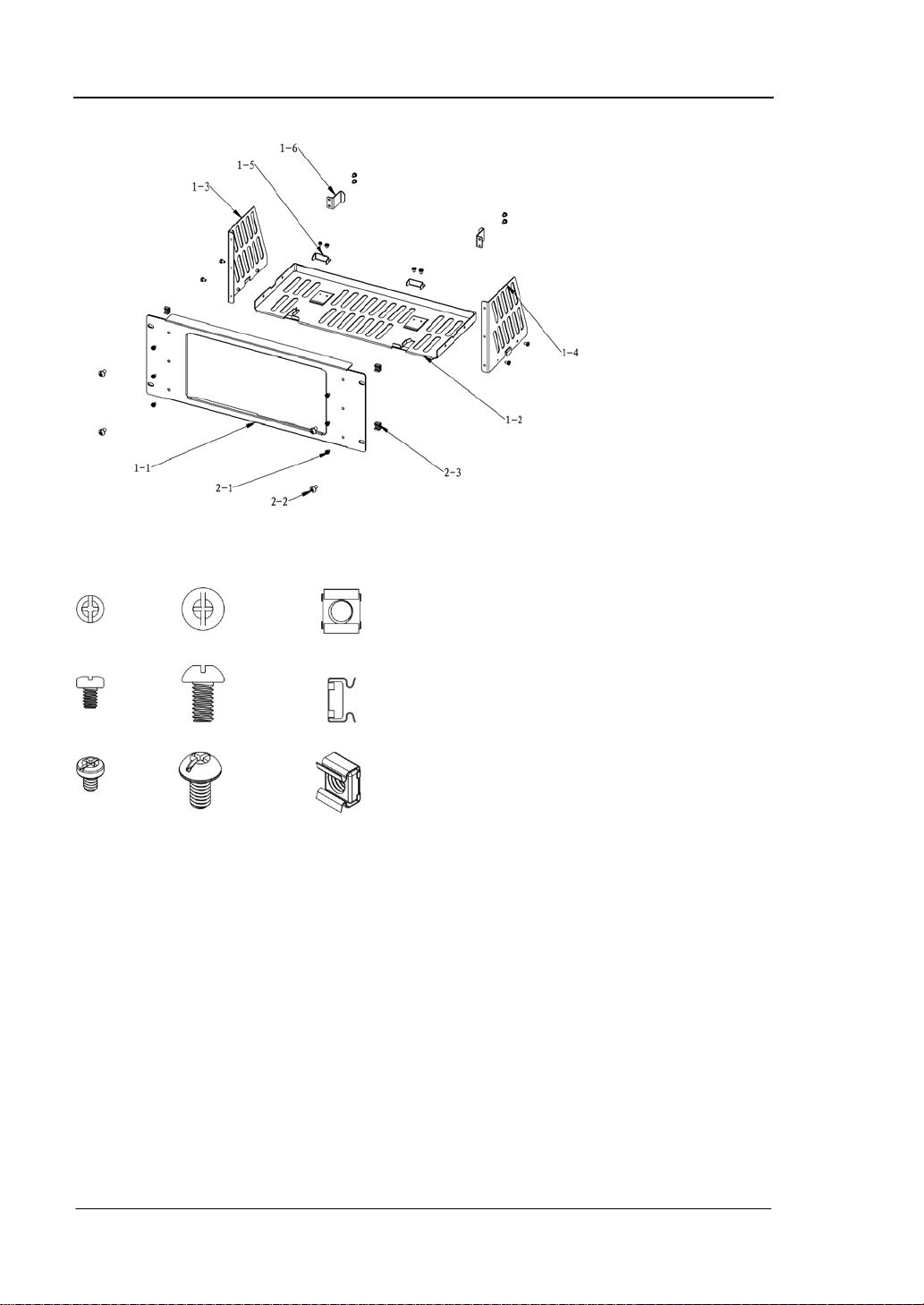
Figure 11 Rack Mount Kit
RIGOL
Kit Parts List
The part list of the rack mount kit (as shown in Figure 11) of DG4000 is as shown in
the table below. Wherein, the “No.” column corresponds to Figure 12 and Figure 13.
Table 1 Kit Parts List
No. Name Qty Part No. Description
1-1 Front Panel 1 RM-DG4-01
1-2 Support Board 1 RM-DG4-02
1-3 Left Plate 1 RM-DG4-03
1-4 Right Plate 1 RM-DG4-04
1-5 Pressure Feet 2 RM-DG4-05
1-6 Built-in Fitting 2 RM-DG4-06
2-1 M4 Screw 18 RM-SCREW-01 M4 x 6 Phil-Slot Pan Head Machine
Screw
2-2 M6 Screw 4 RM-SCREW-02 M6 x 20 Phil-Slot Pan He ad Machine
Screw
2-3 M6 Nut 4 RM-SCREW-03 M6 x 4 Square Machine Lock Nuts
Quick Guide for DG4000
25
RIGOL
Figure 12 Parts of Rack Mount Kit
2-1 2-2 2-3
Figure 13 Screws and Nuts
Installation Tool
PH2 Phillips Screwdriver (recommended).
26
Quick Guide for DG4000

RIGOL
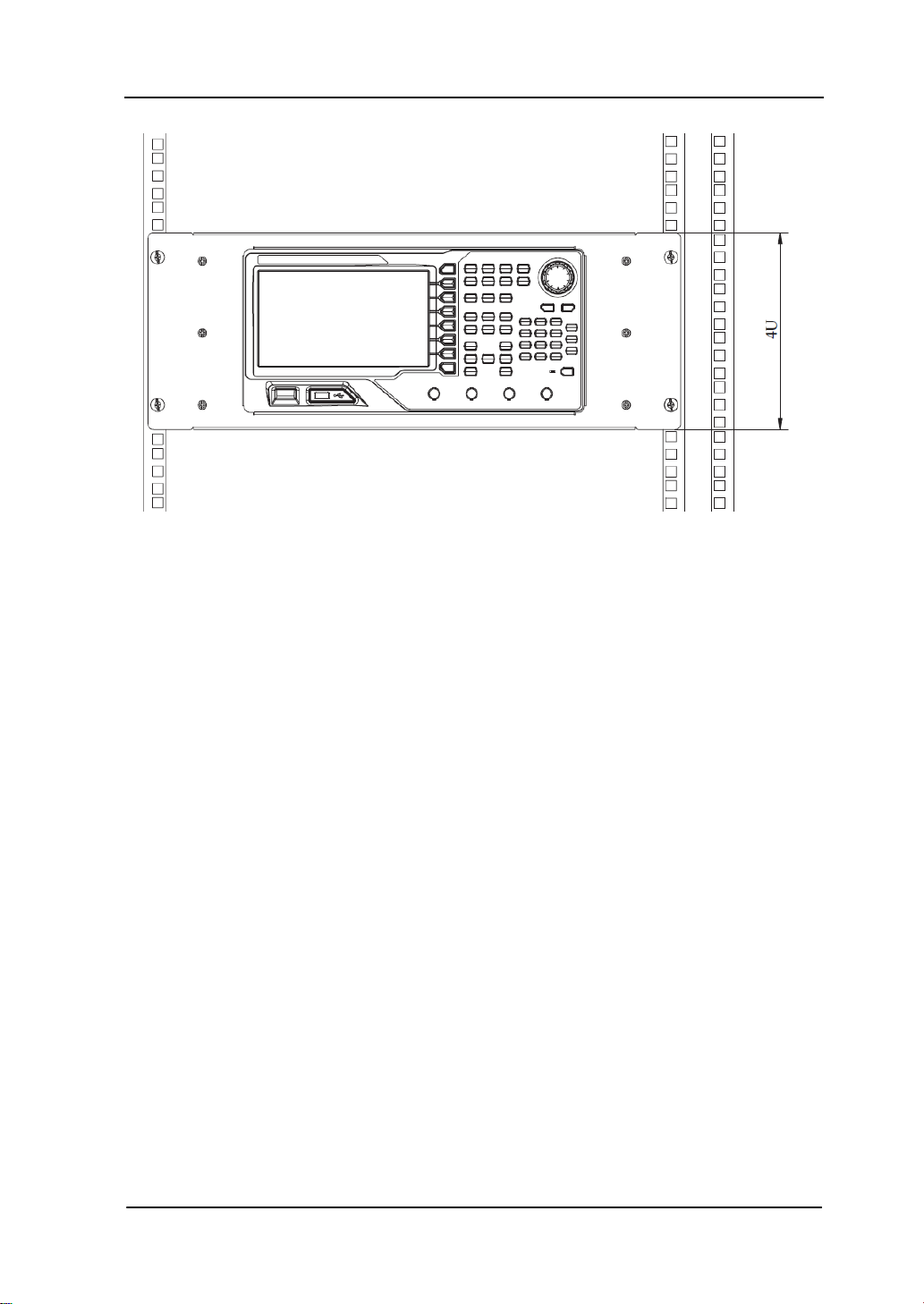
Installation Space
The following requirements must be fulf illed by the machine cabinet in which the
instrument is mounted.
The machine cabinet must be a standard 19-inch one.
At least 4U (177.8 mm) space should be provide d by the machine cabinet.
The depth inside the machine cabinet should not be less than 180 mm.
The dimension of the instrument after being installed is as shown below.
Quick Guide for DG4000
27

RIGOL
28
Quick Guide for DG4000

RIGOL
Quick Guide for DG4000
29
RIGOL
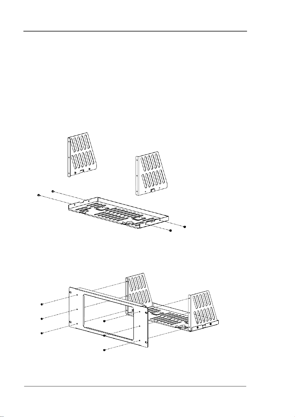
Installation Procedure
Only authorized operators can execute the installation operation. Improper
installation might result in damage of the instrument or incorrect installation of the
instrument on the rack.
1. Install the right and left plates: align the detents of the right and left plates with
the openings on the support board and insert them into the support board
respectively, then fix them with four M4 screws.
2. I nstall the front panel of the rack mount kit: fix the front panel onto the frame
installed in the previous step using six M4 screws.
30
Quick Guide for DG4000

RIGOL
3. Fix the bottom of the instrument: fix the instrument onto the support board
using two pressure feet and four M4 screws.
4. Fix the top of the instrument: fix the top of the instrument using two built-in
fittings and four M4 screws.
Quick Guide for DG4000
31
RIGOL
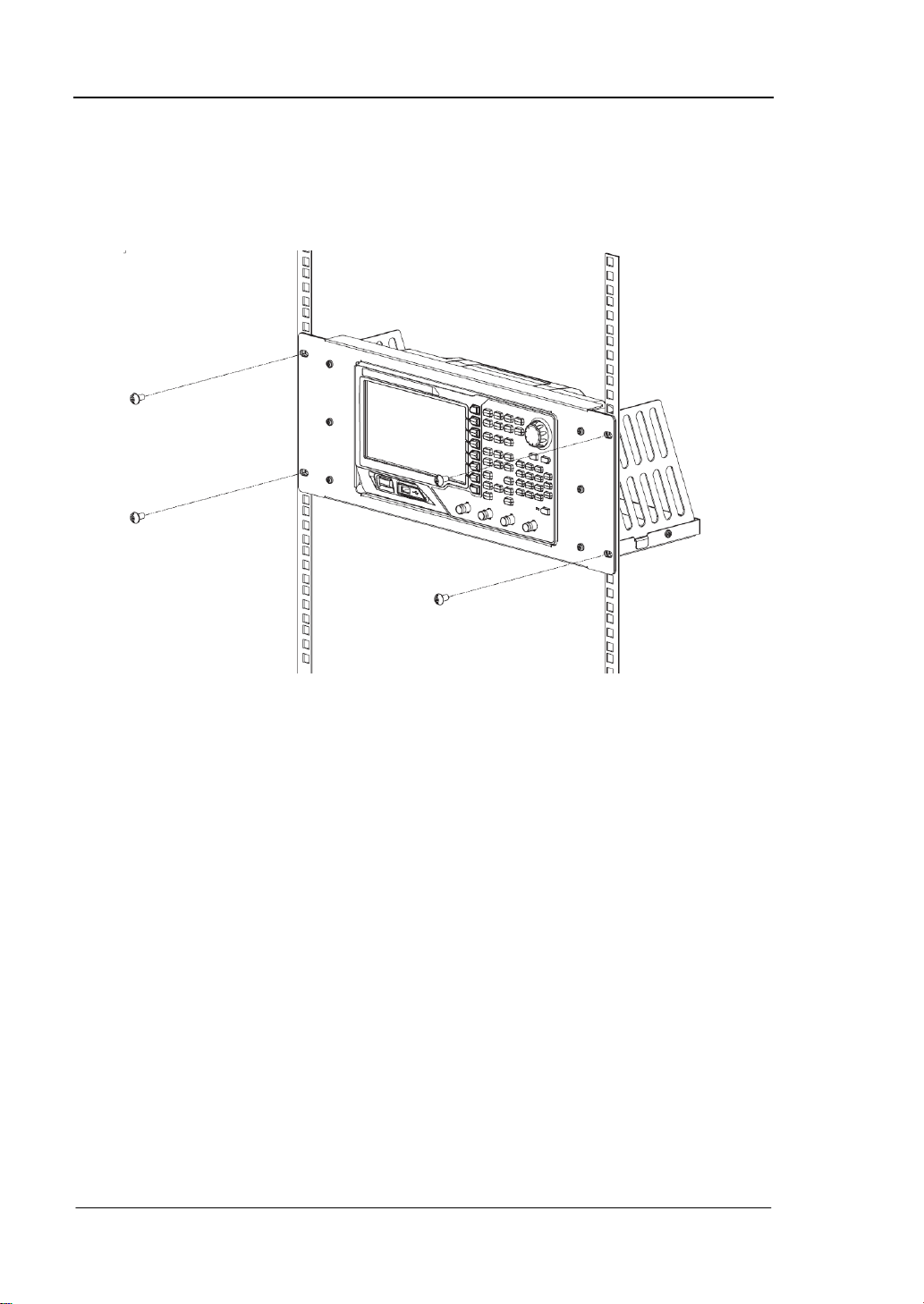
5. L oad into the machine cabinet: mount the rack with the instrument fixed to it
into a standard 19-inch machine cabinet with four M6 screws and four M6
square nuts.
6. Post-installation notice: the rack occupies a he ight of 4U. The holes pointed out
by the arrows are installation holes. Note that they should be aligned with
during installation.
32
Quick Guide for DG4000
RIGOL
Quick Guide for DG4000
33

RIGOL
Troubleshooting
This chapter lists the commonly en count ered failures of DG4000 and their solutions.
When you encounter thos e proble ms, please sol ve t hem f ollowing the correspondin g
steps. If the problem persists, please contact RIGOL and provide your device
information (Utility System Sys Info).
1. The screen is still dark (no display) after power on:
(1) Check if the power is correctly connected.
(2) Check if the power switch is really on.
(3) Restart the instrument after finishing the above inspections.
(4) If it does not work correctly, contact RIGOL for our service.
2. The settings are correct but no waveform is generated:
(1) Check if the BNC cable is correctly connected to the channel output
terminal ([Output1] or [Output2]).
(2) Check if the BNC cable can work correctly.
(3) Check the Output1 or Output2 button, if it is turned on.
(4) Set PowerOn as “Last” and then restart the instrument after finishing the
above inspections.
(5) If it does not work correctly, contact RIGOL fo r our service.
3. The USB storage device cannot be recognized:
(1) Check if the USB storage device can work normally.
(2) Make sure the USB storage device is USB flash storage device. The
generator doesn’t support hard drive-based USB storage device.
(3) Restart the instru m ent, reinsert the USB stora ge devic e and check it.
(4) I f the USB storage device still can not be recognized, please contact
RIGOL.
34
Quick Guide for DG4000
 Loading...