

Page 1

Programming Guide
DG2000 Series
Function/Arb itrary Waveform Generator
Aug. 2019
RIGOL (SUZHOU) TECHNOLOGIES INC.
Page 2

Page 3

RIGOL
Guaranty and Declaration
Copyright
© 2019 RIGOL (SUZHOU) TECHNOLOGIES INC. All Rights Reserved.
Trademark Information
RIGOL is a registered trademark of RIGOL (SUZHOU) TECHNOLOGIES INC.
Publication Number
PGB12100-1110
Software Version
00.02.01
Software upgrade might change or add product features. Please acquire the latest version of the manual
from RIGOL website or contact RIGOL to upgrade the software.
Notices
RIGOL products are covered by P.R.C. and foreign patents, issued and pending.
RIGOL reserves the right to modify or change parts of or all the specifications and pricing policies at
the company’s sole decision.
Information in this publication replaces all previously relea sed materials.
Information in this publication is subject to change without notice.
RIGOL shall not be liable for either incidental or consequential losses in connection with the furnishing,
use, or performance of this manual, as well as any information contained.
Any part of this document is forbidden to be copied, photocopied, or rearranged without prior written
approval of RIGOL.
Product Certification
RIGOL guarantees that this product conforms to the national and industrial standards in China as well as
the ISO9001:2015 standard a nd the ISO14001:2015 standard. Other international standard conformance
certifications are in progress.
Contact Us
If you have any problem or requirement when using our products or this manual, please contact RIGOL.
E-mail: service@rigol.com
Website: www.rigol.com
DG2000 Programming Guide I
Page 4
RIGOL
Tip
For the latest version of this manual, download it from the official website of RIGOL (www.rigol.com).
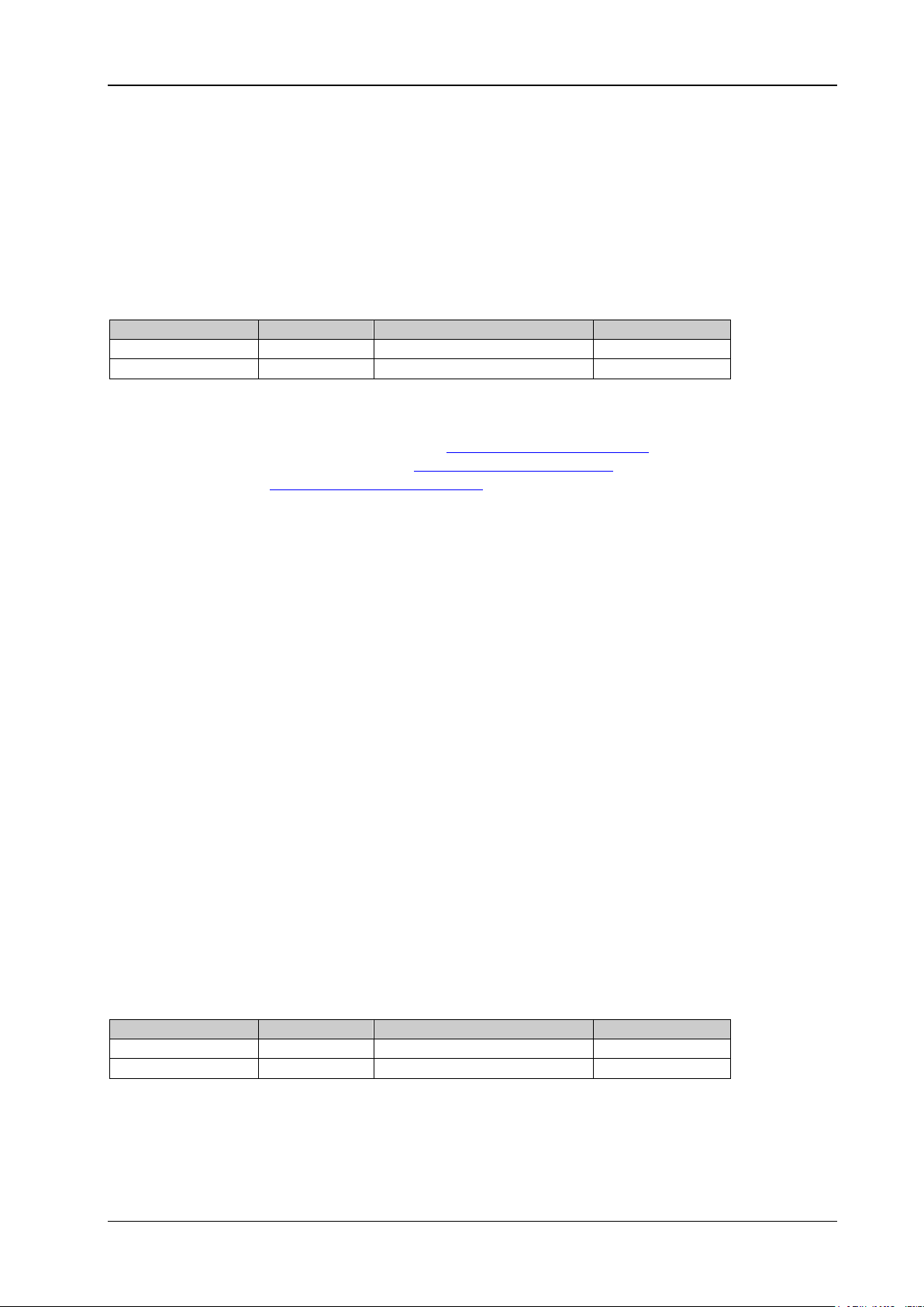
Model
No. of Channels
Max. Output Frequency
DG2052
2
50 MHz
DG2072
2
70 MHz
DG2102
2
100 MHz
Document Overview
This manual introduces how to program the signal generator over the remote interfaces in details.
Main Topics in this Manual:
Chapter 1 Programming Overview
This chapter introduces how to build the remote communication between the signal generator and the PC;
how to control the signal generator remotely. It also introduces the syntax, symbols, parameter types, and
abbreviation rules of the SCPI commands.
Chapter 2 Command System
This chapter introduces the syntax, function, parameters, a nd usages of each DG2000 command in A-Z
order.
Chapter 3 Application Instances
This chapter provides the application examples of the main functions of the signal generator. In the
examples, a series of commands are combined to realiz e the basic functions of the signal generator.
Chapter 4 Programming Examples
This chapter illustrates how to control DG2000 by programming in the d evelopment environments such as
Visual C++, Visual Basic, and LabVIEW.
Chapter 5 Appendix
This chapter provides the command list and the factory settings.
Format Conventions in this Manual:
1. Keys:
The keys on the front panel are usually denoted by the format of "Key Name (Bold) + Text Box". For
example, Pulse/Utility denotes the Utility key.
2. Menu Labels:
The menu labels are usually denoted by the format of "Menu Word (Bold) + Character Shading". For
example, System Setting.
3. Operation Procedures:
"" represents the next step of operation. For example, when the backlight of the Shift key is
illuminated, pressing Pulse/Utility System Setting denotes that first press Pulse/Utility on
the front panel, and then tap the System Setting menu label.
Content Conventions in this Manual:
DG2000 series function/arbitrary waveform generator includes the following models: Unless otherwise
specified, this manual takes DG2102 as an example to introduce each command of the DG2000 series.
II DG2000 Programming Guide
Page 5

Contents RIGOL
Contents
Guaranty and Declaration ......................................................................................................... I
Document Overview ................................................................................................................. II
Chapter 1 Programming Overview...................................................................................... 1-1
Build Remote Communication ....................................................................................................... 1-2
Remote Control Method ................................................................................................................ 1-4
SCPI Command Overview ............................................................................................................. 1-4
Syntax ..................................................................................................................................... 1-4
Symbol Description ................................................................................................................... 1-5
Parameter Type ........................................................................................................................ 1-5
Command Abbreviation ............................................................................................................. 1-6
Chapter 2 Command System ............................................................................................... 2-1
:COUNter Commands ................................................................................................................... 2-2
:COUPling Commands .................................................................................................................. 2-8
:DISPlay Commands ................................................................................................................... 2-19
:HCOPy Commands .................................................................................................................... 2-21
IEEE488.2 Common Commands .................................................................................................. 2-22
:LXI Commands ......................................................................................................................... 2-28
:MEMory Commands .................................................................................................................. 2-29
:MMEMory Commands ................................................................................................................ 2-32
:OUTPut Commands ................................................................................................................... 2-41
:ROSCillator Commands.............................................................................................................. 2-46
:SOURce Commands .................................................................................................................. 2-48
:SOURce:APPLy ...................................................................................................................... 2-49
:SOURce:BURSt ...................................................................................................................... 2-56
:SOURce:FREQuency .............................................................................................................. 2-64
:SOURce:FUNCtion ................................................................................................................. 2-72
:SOURce:HARMonic ................................................................................................................ 2-87
:SOURce:MARKer .................................................................................................................... 2-92
:SOURce[:MOD]:AM ................................................................................................................ 2-94
:SOURce[:MOD]:ASKey ........................................................................................................... 2-98
:SOURce[:MOD]:FM .............................................................................................................. 2-101
:SOURce[:MOD]:FSKey ......................................................................................................... 2-104
:SOURce[:MOD]:PM .............................................................................................................. 2-108
:SOURce[:MOD]:PSKey ......................................................................................................... 2-111
:SOURce[:MOD]:PWM ........................................................................................................... 2-114
:SOURce:MOD ...................................................................................................................... 2-118
:SOURce:PERiod ................................................................................................................... 2-120
:SOURce:PHASe ................................................................................................................... 2-121
:SOURce:PULSe .................................................................................................................... 2-122
:SOURce:SUM ...................................................................................................................... 2-124
:SOURce:SWEep ................................................................................................................... 2-127
:SOURce:TRACe ................................................................................................................... 2-134
:SOURce:TRACK ................................................................................................................... 2-135
:SOURce:VOLTage ................................................................................................................ 2-135
:SYSTem Commands ................................................................................................................ 2-140
:TRIGger Commands ................................................................................................................ 2-155
Chapter 3 Application Instances ......................................................................................... 3-1
To Output Basic Waveforms .......................................................................................................... 3-2
To Output the Arbitrary Waveform ................................................................................................. 3-2
To Output Harmonic ..................................................................................................................... 3-3
To Output AM Modulated Waveform .............................................................................................. 3-3
To Output FSK Modulated Waveform ............................................................................................. 3-4
To Output Sweep Waveform ......................................................................................................... 3-4
To Output Burst Waveform ........................................................................................................... 3-5
To Use the Frequency Counter ...................................................................................................... 3-5
DG2000 Programming Guide III
Page 6

RIGOL Contents
Chapter 4 Programming Examples .................................................................................... 4-1
Programming Preparations ............................................................................................................ 4-2
Excel Programming Examples ........................................................................................................ 4-3
Matlab Programming Example ....................................................................................................... 4-6
LabVIEW Programming Example ................................................................................................... 4-8
Visual Basic Programming Example .............................................................................................. 4-15
Visual C++ Programming Example .............................................................................................. 4-18
Chapter 5 Appendix ............................................................................................................ 5-1
Appendix A: Factory Setting .......................................................................................................... 5-1
Appendix B: Warranty ................................................................................................................... 5-5
IV DG2000 Programming Guide
Page 7

Chapter 1 Programming Overview RIGOL
Chapter 1 Programming Overview
This chapter introduces how to build the remote communication between the signal generator and the PC;
how to control the signal generator remotely. It also introduces the syntax, symbols, parameter types, and
abbreviation rules of the SCPI commands.
Contents in this chapter:
Build Remote Communication
Remote Control Method
SCPI Command Overview
DG2000 Programming Guide 1-1
Page 8
RIGOL Chapter 1 Programming Overview
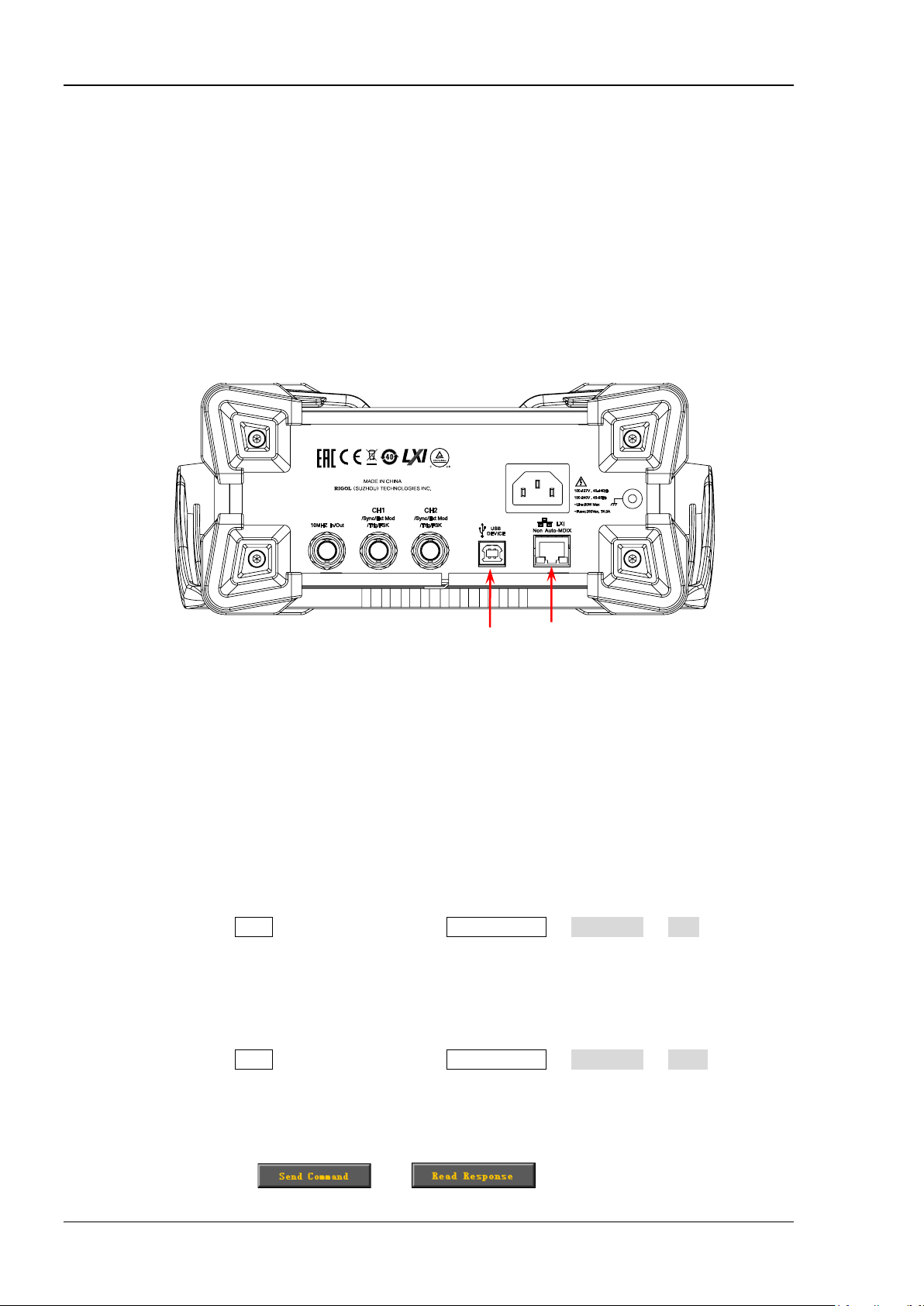
USB DEVICE
LAN
Build Remote Communication
Yo u c an build the remote co mmu nicati on between DG2000 and the PC via the USB (USB DEVICE), LAN, or
GPIB interface (extended from the USB HOST interface by using the US B-GPIB interface converter).
Operation Procedures:
1. Install Ultra Sigma (PC) software
Download the Ultra Sigma common PC software from www.rigol.com and install it according to the
instructions.
2. Connect the analyzer to the PC and configure the interface parameters for the instrument
DG2000 supports the USB, LAN, and GPIB (extended from the USB HOST interface by using the
USB-GPIB interface converter) communication interfaces, as shown in the figure below.
Figure 1-1 DG2000 C ommunication Interface
1) Use the USB interface: connect the USB DEVICE interface on the rear panel of DG2000 and the
USB HOST interface of the PC by using a USB cable. The "Found New Hardware Wizard" dialog
box will be displayed and please install the "USB T est and Measurement Device (IVI)" according to
the instructions (refer to "Remote Control via U SB" in Chapter 3 "R emote Control" in
).
Guide
2) Use the LAN interface:
Make sure that your PC has been accessed to the local area network.
Check whether the local area network where your PC resides supports DHCP or auto IP mode.
If not, you need to acquire the network interface parameters available, such as the IP
address, subnet mask, default gateway, and DNS.
Use the network cable to have DG2000 get access to the local area network.
When the Shift key is illuminated, press Pulse/Utility Interface LAN to configure
the IP address, subnet mask, default gateway, and DNS.
3) Use the GPIB interface:
Extend a GPIB interface by connecting the USB HOST interface on the front panel of DG2000
by using the USB-GPIB interface converter.
Use the GPIB cable to connect the instrument to your PC.
When the Shift key is illuminated, press Pulse/Utility Interface GPIB to set the
GPIB address of the instrument.
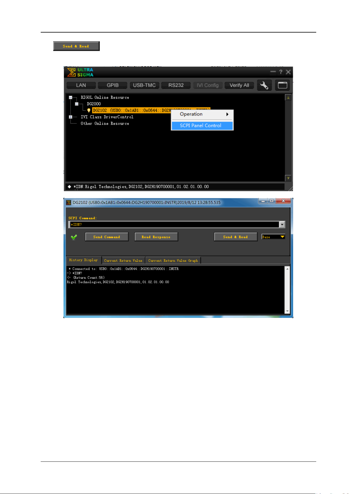
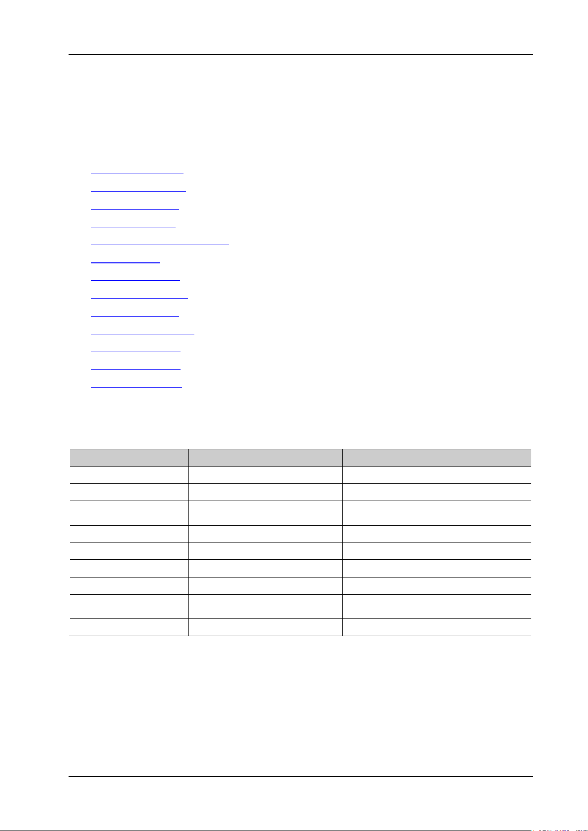
3. Check whether the connection is successful
Run Ultra Sigma, and then search for the resources and right-click the resource name. Select "SCPI
Panel Control" to open the SCPI command control panel. Input a correct command in the pop-up SCPI
DG2000 User
1-2 DG2000 P rogra mming Guide
control panel and click
and in sequence or directly click
Page 9
Chapter 1 Programming Overview RIGOL
to check whether the connection is successful, as shown in the figure below (t he
USB interface is taken as an example).
DG2000 Programming Guide 1-3
Page 10

RIGOL Chapter 1 Programming Overview
Remote Control Method
1. User-defined programming
You can use the SCPI (Standard Commands for Programmable Instruments) commands listed in
Chapter 2 "Command System" of this manual to program and control the instrument in various
development environments (e.g. Visual C++, Visual Basic, and LabVIEW). For details, refer to
descriptions in Chapter 4 "Programming Examples".
2. Send SCPI commands via the PC software
You can use the PC software to send commands to control the signal generator remotely. RIGOL Ultra
Sigma is recommended. You can download the software from RIGOL official website
(www.rigol.com).
SCPI Command Overview
SCPI (Standard Commands for Programmable Instruments) is a standardized instrument programming
language that is built upon the existing standard IEEE 488.1 and IEEE 488.2 and conforms to various
standards, such as the floating point operation rule in IEEE 754 standard, ISO 646 7-bit coded character set
for information interchange (equivalent to ASCII programming). This chapter introduces the syntax,
symbols, parameters, and abbreviation rules of the SCPI commands.
Syntax
The SCPI commands provide a hierarchical tree structure, and consist of multiple subsystems. Each
command subsystem consists of one root keyword and one or more sub-keywords. The command line
usually starts with a colon; the keywords are separated by colons, a nd following the keywords are the
parameter settings available. The command ending with a question mark indicates querying a certain
function. The keywords of the command and the first parameter is separated by a space.
For example,
:SYSTem:COMMunicate:LAN:IPADdress <ip_address>
:SYSTem:COMMunicate:LAN:IPADdress?
SYSTem is the root keyword of the command. COMMunicate, LAN, and IPADdress are the second-level,
third-level, and forth-level keywords respectively. The command string starts with ":" which is also used to
separate the multiple-level keywords. <ip_address> represents the parameters available for setting. "?"
represents query; the instrument returns the corresponding information (the input value or internal setting
value of the instrument) when receiving t he query command. The
command :SYSTem:COMMunicate:LAN:IPADdress and the parameter <ip_address> are separated by a
space.
In some commands with parameters, "," is often used to separate multiple parameters. For example,
:DISPlay:TEXT[:SET] <string>[,x[,y]]
1-4 DG2000 P rogra mming Guide
Page 11

Chapter 1 Programming Overview RIGOL
Symbol Description
The following four symbols are not part of the SCPI command, and they are not sent with the commands,
but taken as delimiters to better describe the parameters in the command.
1. Braces { }
The contents enclosed in the braces can contain multiple parameter options; and the vertical bar is
used to separate multipl e parameter option s. When sending the command, you must select one of the
parameters. For example, :COUPling[<n>]:PHASe:MODE {OFFSet|RATio}.
2. Vertical Bar |
The vertical bar is used to separate multiple parameters. When using the command, you must select
one of the parameters. For example, :COUPling[<n>]:PHASe:MODE {OFFSet|RATio}.
3. Square Brackets []
The contents (command keywords or parameters) in the square brackets can be omitted. If the
parameter is omitted, the instrument will set the parameter to its default. For example, for
the :COUNter:STATIstics[:STATe]? command, send any of the following two commands can achieve
the same effect.
:COUNter:STATIstics?
:COUNter:STATIstics:STATe?
4. Triangle Brackets <>
The parameter enclosed in the angle brackets must be replaced by an effective value. For example,
sending the :COUNter:LEVEl <value> command in :COUNter:LEVEl 1.5 form.
Parameter Type
The command parameters introduced in this manual include 5 types: Bool, Integer, Real, Discrete, and
ASCII String.
1. Bool
The parameter can be set to "ON (1)" or "OFF (0)". For example, :COUNter:HF {ON|1|OFF|0}.
2. Integer
Unless otherwise specified, the parameter can be any integer within the effective value range. Note:
Do not set the parameter to a decimal, otherwise, errors will occur. For example, in
the :DISPlay:BRIGhtness <brightness> command, <bri ghtness> can be any integer from 0 to 100.
3. Real
Unless otherwise noted, the parameter can be any number within the effective value range.
For example, the range of <value> in the :COUNter:LEVEl <value> command is from -2.5 V to 2.5 V.
4. Discrete
The parameters can only be the specified numerical values or characters. For example, in
the :COUPling[<n>]:PHASe:MODE {OFFSet|RATio} command, the parameter can only be OFFSet or
RATio.
5. ASCII String
The parameter can be the combinations of ASCII characters. For example, in
the :MMEMory:LOAD:STATe <filename> command,
<filename> is the filename of the state file to be loaded under the current directory of the external
memory and it can include English characters and numbers.
Besides, you can replace the parameters in many commands with MINimum or MAXimum to set the
parameters to their minimum or maximum value.
DG2000 Programming Guide 1-5
Page 12

RIGOL Chapter 1 Programming Overview
For example, MINimum and MAXimum in the :DISPlay:BRIGhtness {<brightness>|MINimum|MAXimum}
command are used to set the brightness to the minimum or maximum.
Command Abb r eviation
The letters in the commands are case-insensi tive. The commands can be inpu t all in uppercase let ters or in
lowercase letters. For abbreviations, you must enter all the uppercase letters that exist in the command
syntax. For example, the :COUNter:COUPling? command can be abbreviated as :COUN:COUP?.
1-6 DG2000 P rogra mming Guide
Page 13
Chapter 2 Command System RIGOL
Vpp/Vrms/dBm (Relates to the current
amplitude unit to be set.)
Duty Cycle/Modulation
Depth/Brightness/
Chapter 2 Command System
This chapter introduces the syntax, function, parameters, a nd usages of each DG2000 command in A-Z
order.
Contents in this chapter:
:COUNter Commands
:COUPling Commands
:DISPlay Commands
:HCOPy Commands
IEEE488.2 Common Commands
:LXI Commands
:MEMory Commands
:MMEMory Commands
:OUTPut Commands
:ROSCillator Commands
:SOURce Commands
:SYSTem Commands
:TRIGger Commands
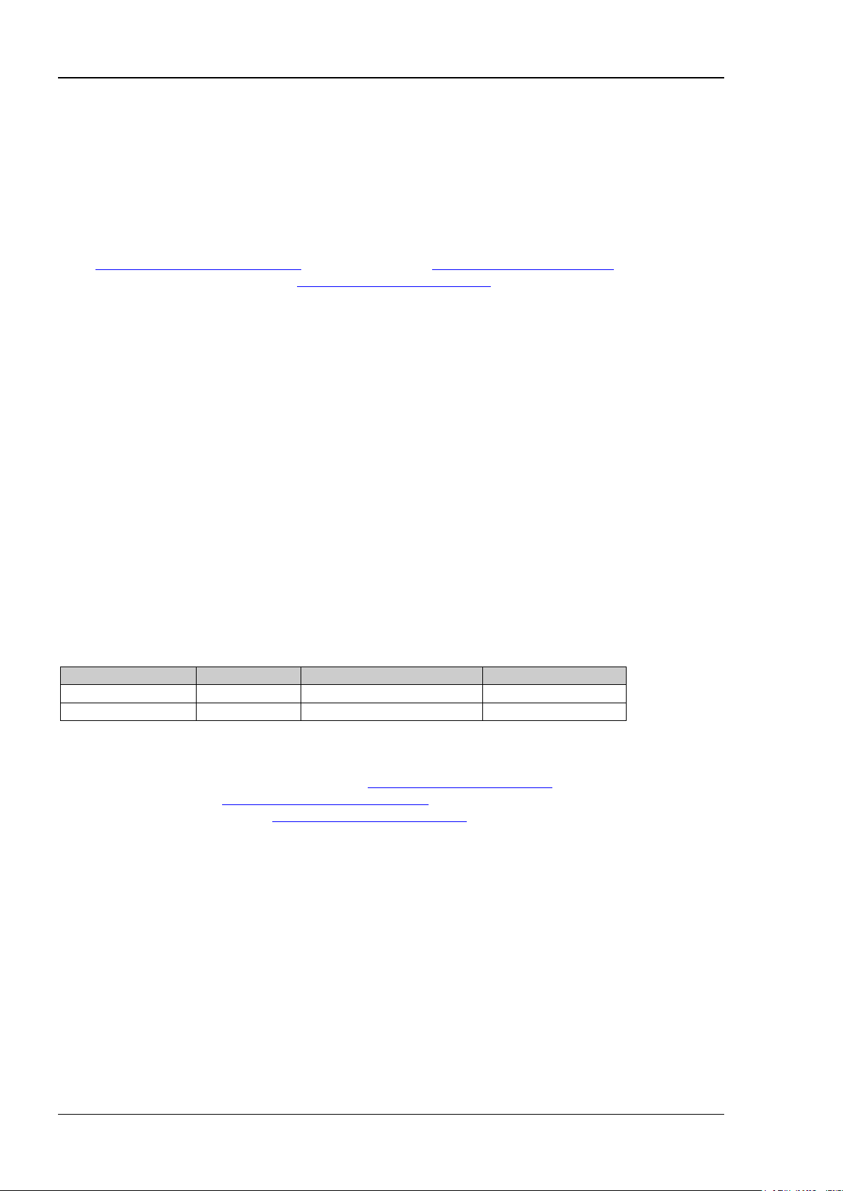
Remarks: In this command system, setting commands relating to the frequency and amplitude
parameters can be sent with units. The units available and the d efault u nit of each parameter are as shown
in the table below.
Parameter Type Units Available Default Unit
Frequency MHz/kHz/Hz/uHz Hz
Sample Rate MSa/s, kSa/s, Sa/s , uSa/s Sa/s
Amplitude Vpp/mVpp/Vrms/mVrms/dBm
Offset Vdc/mV
High Level /Low Level V/mV V
Time Ms/ks/s/ms/us/ns s
Phase ° °
Impedance Ω Ω
Note:
In this manual, the range of the parameter in the command takes DG2102 as an example.
As all the commands are case-insensitive, for DG2000, MHZ (mhz) and MSA/S (msa/s) are interpreted
as megahertz and mega points per second respectively; whereas MVPP (mvpp), MVRMS (mvrms),
MVDC (mvdc), MV (mv), and MS (ms) are in terpreted as millivo lt (peak -peak value), millivolt (effective
value), millivolt (DC), millivolt, and millisecond respectively.
When the output impedance is HighZ, the amplitude unit dBm is invalid.
Vdc
dc
% %
DG2000 Programming Guide 2-1
Page 14

RIGOL Chapter 2 Command System
:COUNter Commands
The :COUNter commands are used to enable or disable the frequency counter; set the related information
of the frequency counter.
[1]
Command List
:COUNter:AUTO
:COUNter:COUPling
:COUNter:GATEtime
:COUNter:HF
:COUNter:LEVEl
:COUNter:MEASure?
:COUNter:SENSitive
:COUNter[:STATe]
:COUNter:STATIstics:CLEAr
:COUNter:STATIstics[:STATe]
[1]
Note
: In the "Command Lis t" in this manual, the parameters in the setting commands and the query
commands are not included and you can refer to the complete introductions of the commands in the text
according to the keywords.
:
2-2 DG2000 Programming Guide
Page 15

Chapter 2 Command System RIGOL
Name
Type
Range
Default
{AC|DC}
Discrete
AC|DC
AC
Name
Type
Range
Default
{USER1|USER2|USER3|
USER4|USER5|USER6}
{USER1|USER2|USER3|USER4|
USER5|USER6}
USER1
USER2
USER3
USER4
USER5
USER6
1.048ms
8.389 ms
134.218 ms
1.074 s
8.590 s
>8.590 s
:COUNter:AUTO
Syntax
:COUNter:AUTO
Description
The instrument will select a proper gate time automatically according to the characteristics of the signal
under test after sending this command.
Remarks
You can also send the
:COUNter:GATEtime command to set the desired gate time.
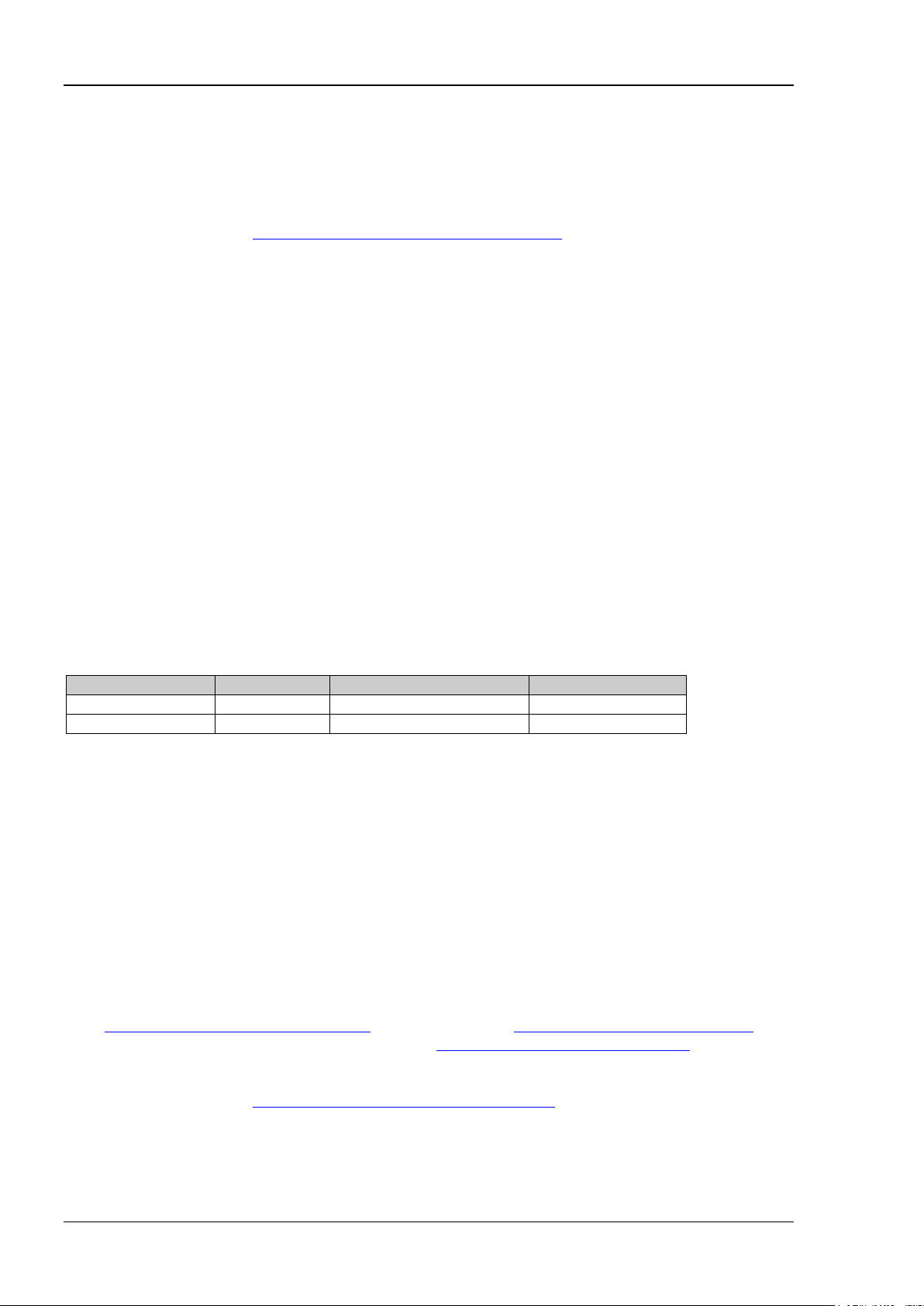
:COUNter:COUPling
Syntax
:COUNter:COUPling {AC|DC}
:COUNter:COUPling?
Description
Sets the coupling mode of the input signal to AC or DC.
Queries the coupling mode of the input signal.
Parameter
Return Format
The query returns AC or DC.
Example
:COUN:COUP DC /*Sets t he coupling mode of the input signal to DC.*/
:COUN:COUP? /*Queries the coupling mode of the input signal and the query returns DC.*/
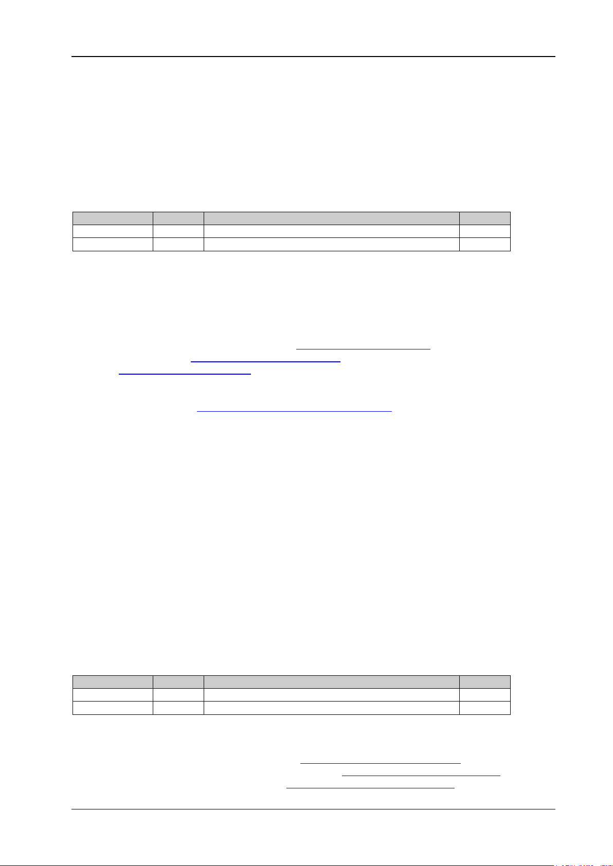
:COUNter:GATEtime
Syntax
:COUNter:GATEtime {USE R1|USER2|USER3|USER4|USER5|USER6}
:COUNter:GATEtime?
Description
Selects the gate time of the measurement system.
Queries the gate time of the measurement system.
Parameter
Discrete
Remarks
The gate time represented by USER1 through USER6 are as shown in the table below.
USER1
For low-frequency signals (for example, the frequency is lower than 5 Hz), you are recommended to
set the gate time to USER6.
Send the
DG2000 Programming Guide 2-3
:COUNter:AUTO command and the instrument will select a proper gate time automatically
Page 16

RIGOL Chapter 2 Command System
Name
Type
Range
Default
{ON|1|OFF|0}
Bool
ON|1|OFF|0
OFF
according to the characteristics of the signal under test. During this process, "AUTO" is displayed in the gate
time area in the frequency counter interface. The gate time currently selected by the instrument will be
displayed in t he gate time area in the frequen cy counter inter face after th e instrument select s a proper gate
time.
Return Format
If you have currently selected a gate time, the query returns USER1, USER2, USER3, USER4, USER5, or
USER6 that corresponds to the specified gate time. If you send the
the instrument to select a proper gate time automatically, then during thi s process, the quer y returns
"AUTO"; and returns USER1, USER2 , USER3 , USER4 , USER5, o r USER6 af ter a proper g ate time i s selec ted
by the instrument.
Example
:COUN:GATE USER2 /*Sets the gate time of the measurement system to USER2 (10.48 ms).*/
:COUN:GA TE? /*Queries the gate time o f the measur ement system an d the query retu rns USER2.* /
:COUNter:AUTO command to enable
:COUNter:HF
Syntax
:COUNter:HF {ON|1|OFF|0}
:COUNter:HF?
Description
Enables or disables the high frequency rejection function of the frequency counter.
Queries the on/off status of the high frequency rejection function of the frequency counter.
Parameter
Remarks
Enable the high frequency rejection when low-frequency signal with less than 150 kHz fre quency is
measured to filter out the high-frequency noise interference and improve the measurement accuracy.
Disable the high freq uency rejection when high-frequency signal with greater than 150 kHz freq uency is
measured. At this time, the maximum input frequency can be 240 MHz.
Return Format
The query returns ON or OFF.
Example
:COUN:HF ON /*Enables the high frequency rejection function of the frequency counter.*/
:COUN:HF? / *Queries the on/off status of the high frequen cy rejection function of the frequency
counter and the query returns ON.*/
:COUNter:LEVEl
Syntax
:COUNter:LEVEl {<value>|MINimum|MAXimum}
:COUNter:LEVEl? [MINimum|MAXimum]
Description
Sets the trigger level of the frequency counter.
Queries the trigger level of the frequency counter.
2-4 DG2000 Programming Guide
Page 17

Chapter 2 Command System RIGOL
Name
Type
Range
Default
<value>
Real
-2.5 V to 2.5 V
0V
Parameter
Remarks
The frequency counte r starts measuri ng when the input s ignal reaches the specified trigger le vel.
The minimum resolution is 6 mV.
Return Format
The query returns the trigger level in scientific notation. The returned value contains 7 effective digits, for
example, 1.500000E+00 (the trigger level is 1.5 V).
Example
:COUN:LEVE 1.5 / *S ets the trigger level of the frequency counter to 1.5 V.*/
:COUN:LEVE? /*Queries the trigger level of the frequency counter and the query returns
1.500000E+00.*/
:COUNter:MEASure?
Syntax
:COUNter:MEASure?
Description
Queries the measurement results of the frequency counter.
Remarks
When the frequency counter is in the "R UN" or "SINGLE" state, send this command to query the
measurement values. When the frequency counter is in the "STOP" state, send this command to query the
measurement values of the last measurement.
Return Format
The query returns a string consisting of 5 parts (representing the frequency, period, duty cycle, positive
pulse width, and negative pulse width respectively), separated by commas. Each part is expressed in
scientif ic notation and contains 10 effective digits, for example,
2.000000000E+03,5.000000000E-04,4.760800000E+01,2.380415000E-04,
2.619585000E-04 (representing the measurement result: 2 kHz frequency, 500 us period, 47.608% duty
cycle, 238.0415 us positive pulse width, and 261.9585 us negative pulse width).
When the frequency counter function is disabled, the query returns 0.000000000E+00,0.000000000E+00,
0.000000000E+00,0.000000000E+00,0.000000000E+00.
Example
:COUN:MEAS? /*Queries the measurement results of the frequency counter and the query returns
2.000000000E+03,5.000000000E-04,
4.760800000E+01,2.380415000E-04,2.619585000E-04.*/
:COUNter:SENSitive
Syntax
:COUNter:SENSitive {LOW|HIGh}
:COUNter:SENSitive? [LOW|HIGh]
Description
Sets the trigger se nsitivity of the frequency counter.
Queries the trigger sensitivity of the frequency counter.
DG2000 Programming Guide 2-5
Page 18

RIGOL Chapter 2 Command System
Name
Type
Range
Default
{LOW|HIGh}
Real
LOW|HIGh
LOW
Name
Type
Range
Default
{ON|1|OFF|0|RUN|STOP|SINGLE}
Discrete
ON|1|OFF|0|RUN|STOP|SINGLE
OFF
Parameter
Remarks
A higher sensitivity is recommended for the signal with a small amplitude; a low sensitivity is recommended
for a low-frequency signal with a large amplitude or a signal with a slow rising edge to ensure the accuracy
of the measurement result.
Return Format
The query returns LOW or HIG.
Example
:COUN:SENS LOW /*Sets the trigger sensitivity of the frequency counter to LOW.*/
:COUN:SENS? /*Queries the trigger sensitivity of the frequency counter and the query returns LOW.*/
:COUNter[:STATe]
Syntax
:COUNter[:STATe] {ON|1|OFF|0|RUN|STOP|SINGLE}
:COUNter[:STATe]?
Description
Sets the status of t he frequency counter.
Queries the status of the frequency counter.
Parameter
Remarks
"ON" and "1" denote enabling the freque ncy counter function; "OFF" and "0" denote disabling the
frequency counter funct io n; "RUN", "S TOP", and "SINGLE" denote setting the runn ing status of the
frequency counter to "run", "sto p", and "single" respectively.
The command for setting the operating status (the parameter is RUN, STOP, or SINGLE) is only valid
when the frequency counter function is enabled.
When the frequency counter function is enab led, the sync output of CH2 will be disabled.
In the "RUN" status, the frequency counter measures the input signal continuously according to the
current configuration. In the "SINGLE" status, the frequency counter executes a measurement, then
enters the "STOP" status, and then stops measurement. In the "STOP" status, the frequency counter
stops measuring.
When the frequency counter is enabled, the default operating status is "RUN", and the instrument
measures the input signal continuously according to the current configuration. At this point, if you
send the :COUNter:STATe SINGLE command, the frequency counter enters the "Single" status,
finishes the current me asurement, and then stops; if you send the :COUNter:STATe STOP command,
the frequency counter enters the "STOP" state immediately.
When the frequency counter is in the "STOP" status, the frequency counter performs a measurement
and then enters the "STOP" statu s to stop th e measuremen t each ti me y ou send the :COUNter:STATe
SINGLE command.
Return Format
When the frequency counter function is enabled, the query returns the current operating status (RUN, STOP ,
or SINGLE); when the frequency counter function is disabled, the query returns OFF.
Example
:COUN OFF /*Disables the frequency counter function.*/
2-6 DG2000 Programming Guide
Page 19

Chapter 2 Command System RIGOL
Name
Type
Range
Default
{ON|1|OFF|0}
Bool
ON|1|OFF|0
OFF
:COUN? /*Queries the status of the frequency counter and the query returns OFF.*/
:COUN 1 /*Enables the frequency counter function.*/
:COUN? /*Queries the status of the frequency counter and the query returns RUN (the default
operating status).*/
:COUN STOP /*Sets the operating status of the frequency counter to "STOP".*/
:COUN? /*Queries the status of the frequency counter and the query returns STOP.*/
:COUNter:STATIstics:CLEAr
Syntax
:COUNter:STATIstics:CLEAr
Description
Clears the statistics results.
Remarks
This command is only valid when the statistical function of the frequency counte r is enabled
:COUNter:STATIstics[:STATe]).
(
The statistics results are cleared automatically when the statistical function of the frequency counter is
disabled.
:COUNter:STATIstics[:STATe]
Syntax
:COUNter:STATIstics[:STATe] {ON|1|OFF|0}
:COUNter:STATIstics[:STATe]?
Description
Enables or disables the statistical function of the measurement results of the frequency counter.
Queries the on/off status of the stati stical function of the measurement results of the frequency counter.
Parameter
Return Format
The query returns ON or OFF.
Example
:COUN:STATI ON /*Enables the statistical function of the measurement results of the frequency
counter.*/
:COUN:STATI? /*Queries the on/off status of the statistical function of the measurement results of the
frequency counter and the query returns ON.*/
DG2000 Programming Guide 2-7
Page 20

RIGOL Chapter 2 Command System
:COUPling Commands
The :COUPling commands are used to set the related information of the channel frequency coupling,
amplitude coupling, and phase coupling; enable and disable the three coupling functions.
Command List:
:COUPling[<n>]:AMPL:DEViation
:COUPling[<n>]:AMPL:MODE
:COUPling[<n>]:AMPL:RATio
:COUPling[<n>]:AMPL[:STATe]
:COUPling[<n>]:FREQuency:DEViation
:COUPling[<n>]:FREQuency:MODE
:COUPling[<n>]:FREQuency:RATio
:COUPling[<n>]:FREQuency[:STATe]
:COUPling[<n>]:PHASe:DEViation
:COUPling[<n>]:PHASe:MODE
:COUPling[<n>]:PHASe:RATio
:COUPling[<n>]:PHASe[:STATe]
:COUPling[<n>][:STATe]
:COUPling[<n>]:TRIgger[:STATe]
Note: The coupling function is only available when both the waveforms of the two channels are basic
waveforms (Sine, Square, Ramp, or Arbitrary waveform).
2-8 DG2000 Programming Guide
Page 21
Chapter 2 Command System RIGOL
Name
Type
Range
Default
[<n>]
Discrete
1|2
1
<deviation>
Real
-19.998 Vpp to 19.998 Vpp
0 Vpp
Name
Type
Range
Default
[<n>]
Discrete
1|2
1
{OFFSet|RATio}
Discrete
OFFSet|RATio
RATio
:COUPling[<n>]:AMPL:DEViation
Syntax
:COUPling[<n>]:AMPL:DEViation <deviation>
:COUPling[<n>]:AMPL:DEViation?
Description
Sets the amplitude deviation in the amplitude coupling of the specified channel.
Queries the amplitude deviation in the amplitude coupling of the specified channel.
Parameter
Remarks
When [<n>] is omitted, the commands set and query the related parameters of CH1 by default.
Select the desired amplitu de coupling mode (
amplitude deviation or amplitude ratio (
coupling function (
:COUPling[<n>]:AMPL[:STATe]). You cannot set the amplitude coupling mode and
:COUPling[<n>]:AMPL:MODE) and set the corresponding
:COUPling[<n>]:AMPL:RATio) before enabling the amplitude
amplitude deviation/ratio after the amplitude coupling function is enabled.
When the amplitude coupling function is disabled, if the current amplitude coupling mode is amplitude
deviation, sending this command can set the amplitude devi ation; if the current amplitude coupling
mode is amplitude ratio, sending this command can set the amplitude coupling mode to amplitude
deviation and set the amplitude deviation.
Return Format
The query returns the amplitude deviation in scientific notation. The returned value contains 7 effective
digits, for example, 1.000000E+00 (the amplitude deviation is 1 Vpp).
Example
:COUP1:AMPL:DEV 1 /*Sets the amplitude deviation in the amp litude coupling of CH1 to 1 Vpp.*/
:COUP1:AMPL:DEV? /*Queries the amplitude deviation in the am plitude coupling of CH1 and the
query returns 1.000000E+00.*/
:COUPling[<n>]:AMPL:MODE
Syntax
:COUPling[<n>]:AMPL:MODE {OFFSet|RATio}
:COUPling[<n>]:AMPL:MODE?
Description
Sets the amplitude coupling mode of the specified channel to OFFSet (amplitude deviation) or RATio
(amplitude ratio).
Queries the selected amplitude coupling mode of the specified channel.
Parameter
Remarks
When [<n>] is omitted, the commands set and query the related parameters of CH1 by default.
Amplitude deviation mode: the amplitudes of CH1 and CH2 have a certain deviation relation. The
parameter relations are A
source is CH2). Wherein, A
DG2000 Programming Guide 2-9
CH2=ACH1+ADev
is the amplitude of CH1, A
CH1
(the reference source is CH1); A
is the amplitude of CH2 and A
CH2
CH1=ACH2-ADev
(the reference
is the set
Dev
Page 22
RIGOL Chapter 2 Command System
Name
Type
Range
Default
[<n>]
Discrete
1|2
1
<value>
Real
0.001 to 1000
1
amplitude deviation.
Amplitude ratio mode: the amplitudes of CH1 and CH2 have a certain ratio relation. The parameter
relations are A
CH2=ACH1*ARatio
CH2). Wherein, A
(the reference source is CH1); A
is the amplitude of CH1, A
CH1
CH1=ACH2/ARatio
is the amplitude of CH2, and A
CH2
(the reference source is
is the set
Ratio
amplitude ratio.
If the amplitude of CH1 or CH2 exceeds the amplitu de upper limit or lower lim it of the channel af ter the
channel coupling, the instrument will automatically adjust the amplitude upper limit or lower limit of
the other channel to avoid parameter over-range.
Select the desired amplitude coupling mode and set the corresponding amplitude deviation
:COUPling[<n>]:AMPL:DEViation) or amplitude ratio (:COUPling[<n>]:AMPL:RATio) before enabling
(
the amplitude coup ling function (
:COUPling[<n>]:AMPL[:STATe]). You cannot set the amplitude
coupling mode and amplitude deviation/ratio after the amplitude coupling function is enabled.
Return Format
The query returns OFFS or RAT.
Example
:COUP1:AMPL:MO D E OFFS /*Sets the amplitude coupling mode of CH1 to amplitude deviation.*/
:COUP1:AMPL:MODE? /*Queries the selected amplitude coupling mode of CH1 and the query
returns OFFS.*/
:COUPling[<n>]:AMPL:RATio
Syntax
:COUPling[<n>]:AMPL:RATio {<value>|MINimum|MAXimum}
:COUPling[<n>]:AMPL:RATio?
Description
Sets the amplitude ratio in the amplitude coupling of the specified channel.
Queries the amplitude ratio in the amplitude coupling of the specified channel.
Parameter
Remarks
When [<n>] is omitted, the commands set and query the related parameters of CH1 by default.
Select the desired amplitu de coupling mode (
amplitude deviation (
amplitude coupling function (
:COUPling[<n>]:AMPL:DEViation) or amplitude ratio before enabling the
:COUPling[<n>]:AMPL[:STATe]). You cannot set the amplitude coupling
:COUPling[<n>]:AMPL:MODE) and set the corresponding
mode and amplitude deviation/ratio after the amplitude coupling function is enabled.
When the amplitude coupling function is disabled, if the current amplitude coupling mode is amplitude
ratio, sending this command can set the amplitude ratio; if the current amplitude coupling mode is
amplitude deviation, sending this command can set the amplitude coupling mode to am plitude ratio
and set the amplitude ratio.
Return Format
The query returns the amplitude ratio in scientific notation. The returned value conta ins 7 effective digits,
for example, 1.123000E+00 (the amplitude ratio is 1.123).
Example
:COUP1:AMPL:RAT 1.123 /*Sets the amplitude ratio in the amplitude coupling of CH1 to 1.123.*/
:COUP1:AMPL:RAT? /*Queries the amplitude ratio in the amplitude coupling of CH1 and the query
returns 1.123000E+00.*/
2-10 DG2000 Programming Guide
Page 23
Chapter 2 Command System RIGOL
Name
Type
Range
Default
[<n>]
Discrete
1|2
1
{ON|1|OFF|0}
Bool
ON|1|OFF|0
OFF
Name
Type
Range
Default
[<n>]
Discrete
1|2
1
<deviation>
Real
-99.999 999 999 9 MHz to 99.999 999 999 9 MHz
0Hz
:COUPling[<n>]:AMPL[:STATe]
Syntax
:COUPling[<n>]:AMPL[:STATe] {ON|1|OFF|0}
:COUPling[<n>]:AMPL[:STATe]?
Description
Enables or disables the amplitude coupling function of the specified channel.
Queries the on/off status of the amplitude coupling function of the specified channel.
Parameter
Remarks
When [<n>] is omitted, the commands set and query the related parameters of CH1 by default.
After the amplitude coupling functi on is enabled, CH1 and CH2 take each other as the ref erence source.
When the amplitude of one channel (thi s channel is taken as the reference source) is modified, the
amplitude of the other channel is automatically modified accordingly and always keeps the specified
amplitude deviation or ratio with that of the reference channel.
Select the desired amplitu de coupling mode (
amplitude deviation (
:COUPling[<n>]:AMPL:RATio) before enabling the amplitude coupling function. You cannot set
ratio(
the amplitude coupling mode and amplitude deviat ion/ratio after the amplitude coupling function is
enabled.
You can also send the
on/off status of the amplitude coupling function.
Return Format
The query returns ON or OFF.
Example
:COUP1:AMPL ON /*Enables the amplitude coupling function of CH1.*/
:COUP1:AMPL? /*Queries the on/off status of the amplitude coupling function and the query returns ON.*/
:COUPling[<n>]:AMPL:DEViation) or amplitude
[:SOURce[<n>]]:VOLTage:COUPle[:STATe] command to set and query the
:COUPling[<n>]:AMPL:MODE) and set the corresponding
:COUPling[<n>]:FREQuency:DEViation
Syntax
:COUPling[<n>]:FREQ uen c y:DEV ia ti on <de via ti on >
:COUPling[<n>]:FREQuency:DEViation?
Description
Sets the frequency deviation in the frequency coupling of the specified channel .
Queries the frequency deviation in the frequency coupling of the specified channel.
Parameter
Remarks
When [<n>] is omitted, the commands set and query the related parameters of CH1 by default.
Select the desired frequency coupling mode (
corresponding frequency deviation or frequency ratio (
enabling the frequency coupling function (
DG2000 Programming Guide 2-11
:COUPling[<n>]:FREQuency:MODE) and set the
:COUPling[<n>]:FREQuency:RATio) before
:COUPling[<n>]:FREQuency[:STATe]). You cannot set the
Page 24
RIGOL Chapter 2 Command System
Name
Type
Range
Default
[<n>]
Discrete
1|2
1
{OFFSet|RATio}
Discrete
OFFSet|RATio
RATio
frequency coupling mode and frequency deviation/ratio after the frequency coupling function is
enabled.
When the frequency coupling function is disabled, if the current frequency coupling mode is frequency
deviation, sending this command can s et the frequency de viation; if the current frequency coupling
mode is frequency ratio, sending this command can set the freque ncy coupling mode to frequency
deviation and set the frequency deviation.
You can also send the
[:SOURce[<n>]]:FREQuency:COUPle:OFFSet command to set and query the
frequency deviation in the frequency coupling.
Return Format
The query returns the frequency deviati on in scientific notation. The returned value contains 7 effective
digits, for example, 1.000000E +02 (the frequency deviation is 100 Hz).
Example
:COUP1:FREQ:DEV 100 /*Set the frequency deviation in the frequency coupling of CH1 to 100 Hz.*/
:COUP1:FREQ:DEV? /*Queries the frequency deviation in the frequency coupling of CH1 and the
query returns 1.000000E+02.*/
:COUPling[<n>]:FREQuency:MODE
Syntax
:COUPling[<n>]:FREQuency:MODE {OFFSet|RATio}
:COUPling[<n>]:FREQuency:MODE?
Description
Sets the frequency coupling mode to frequency deviation (OFFSet) or frequency ratio (RATio).
Queries the selected frequency coupling mode of the specified channel.
Parameter
Remarks
When [<n>] is omitted, the commands set and query the related parameters of CH1 by default.
Frequency deviation mode: the frequencies of CH1 and CH2 have a certain deviation relation. The
parameter relations are F
source is CH2). Wherein, F
CH2=FCH1+FDev
is the frequency of CH1, F
CH1
(the reference source is CH1); F
CH1=FCH2-FDev
is the frequency of CH2, and F
CH2
(the reference
is the
Dev
frequency deviation .
Frequency ratio mode: the frequencies of CH1 and CH2 have a certain ratio relation. The parameter
relations are F
CH2=FCH1*FRatio
CH2). Wherein, F
(the reference source is CH1); F
is the frequency of CH1, F
CH1
CH1=FCH2/FRatio
is the frequency of CH2, and F
CH2
(the reference source is
is the set
Ratio
frequency ratio.
If the frequency of CH 1 or CH2 exceeds the f requency upper limit or lower limit of the channel after the
channel coupling, the instrument will automatically adjust the frequency upper limit or lower limit of
the other channel to avoid parameter over-range.
Select the desired frequency coupling mode and set the corresponding frequency deviation
:COUPling[<n>]:FREQuency:DEViation) or frequency ratio (:COUPling[<n>]:FREQuency:RATio)
(
before enabling the fre quency coupling function (
:COUPling[<n>]:FREQuency[:STATe]). You cannot
set the frequency coupling mode and frequency deviation/ratio after the frequency coupling function is
enabled.
You can also send the
[:SOURce[<n>]]:FREQuency:COUPle:MODE command to set and query the
frequency coupling mode of the specified channel.
Return Format
The query returns OFFS or RAT.
2-12 DG2000 Programming Guide
Page 25
Chapter 2 Command System RIGOL
Name
Type
Range
Default
[<n>]
Discrete
1|2
1
<value>
Real
0.000 001 to 1 000 000
1
Example
:COUP1:FREQ:MODE OFFS /*Sets the frequency coupling mode of CH1 to frequency deviation.*/
:COUP1:FREQ:MODE? /*Queries the selected frequency coupling mode and the query returns OFF S. */
:COUPling[<n>]:FREQuency:RATio
Syntax
:COUPling[<n>]:FREQuency:RATio {<value>|MINimum|MAXimum}
:COUPling[<n>]:FREQuency:RATio?
Description
Sets the frequency ratio in the frequency coupling of the specified channel.
Queries the frequency ratio in the frequency coupling of the specified channel.
Parameter
Remarks
When [<n>] is omitted, the commands set and query the related parameters of CH1 by default.
Select the desired frequency coupling mode (
corresponding frequency deviation (
enabling the frequency coupling function (
frequency coupling mode and frequency deviation/ratio after the frequency coupling function is
enabled.
When the frequency coupling function is disabled, if the current frequency coupling mode is frequency
ratio, sending this command can set the frequency ratio; if the current frequency coupling mode is
frequency deviation, sending this command can set the frequency coupling m ode to frequency ratio
and set the frequency ratio.
You can also send the
frequency ratio in the frequency coupling.
Return Format
The query returns the frequency ratio in scientific notation. The returned value contains 7 effective digits,
for example, 1.001230E+02 (the frequency ratio is 100.123).
Example
:COUP1:FREQ:RAT 100.123 / *S ets the frequency ratio in the frequency coupling of CH1 to 100.123.*/
:COUP1:FREQ:RAT? /*Queries the frequency ratio in the frequency coupling of CH1 and the query
returns 1.001230E+02.*/
[:SOURce[<n>]]:FREQuency:COUPle:RATio command to set and query the
:COUPling[<n>]:FREQuency:DEViation) or frequency ratio before
:COUPling[<n>]:FREQuency:MODE) and set the
:COUPling[<n>]:FREQuency[:STATe]). You cannot set the
:COUPling[<n>]:FREQuency[:STATe]
Syntax
:COUPling[<n>]:FREQuency[:STATe] {ON|1|OFF|0}
:COUPling[<n>]:FREQuency[:STATe]?
Description
Enables or disables the frequency coupling function of the specified channel.
Queries the on/off status of the frequency coupling function o f the specified channel.
DG2000 Programming Guide 2-13
Page 26
RIGOL Chapter 2 Command System
Name
Type
Range
Default
[<n>]
Discrete
1|2
1
{ON|1|OFF|0}
Bool
ON|1|OFF|0
OFF
Name
Type
Range
Default
[<n>]
Discrete
1|2
1
<deviation>
Real
-360° to 360°
0
Parameter
Remarks
When [<n>] is omitted, the commands set and query the related parameters of CH1 by default.
Select the desired frequency coupling mode and set the corresponding frequency deviation or
frequency ratio when the frequency coupling function is disabled. After the frequency coupling
function is enabled, CH1 and CH2 take each other as the r eference source. When the frequency of one
channel (this channel is taken as the reference source) is modified, the frequency of the other channel
is automatically modified accordingly and always keeps the specified frequency deviation or ratio with
that of the reference channel.
Select the desired frequency coupling mode (
corresponding frequency deviation (
:COUPling[<n>]:FREQuency:RATio) before enabling the frequency coupling function. You cannot set
(
:COUPling[<n>]:FREQuency:DEViation) or frequency ratio
:COUPling[<n>]:FREQuency:MODE) and set the
the frequency coupling mode and frequency deviation/ratio after the frequency coupling function is
enabled.
You can also send the
[:SOURce[<n>]]:FREQuency:COUPle[:STATe] command to set and query the
on/off status of the frequency coupling function.
Return Format
The query returns ON or OFF.
Example
:COUP1:FREQ ON /*Enables the frequency coupling function of CH1.*/
:COUP1:FREQ? /*Quer ies the on/off status of the frequency coupl ing function of CH1 and the query
returns ON.*/
:COUPling[<n>]:PHASe:DEViation
Syntax
:COUPling[<n>]:PHASe:DEViation <deviation>
:COUPling[<n>]:PHASe:DEViation?
Description
Sets the phase deviation in the phase coupling of the specified channel.
Queries the phase deviation in the phase coupling of the specified channel.
Parameter
Remarks
When [<n>] is omitted, the commands set and query the related parameters of CH1 by default.
Select the desired phase coupling mode (
phase deviation or phase ratio (
function (
:COUPling[<n>]:PHASe[:STATe]). You cannot set the phase coupling mode and phase
:COUPling[<n>]:PHASe:RATio) before enabling the phase coupling
:COUPling[<n>]:PHASe:MODE) and set the corre sponding
deviation/ratio after the phase coupling function is enabled.
When the phase coupling function is disabled, if the current phase coupling mode is phase deviation,
sending this command can set the phase deviation; if the current phase coupling mode is phase ratio,
sending this command can set the phase coupling mod e to phase deviation and set the phase
deviation.
2-14 DG2000 Programming Guide
Page 27
Chapter 2 Command System RIGOL
Name
Type
Range
Default
[<n>]
Discrete
1|2
1
{OFFSet|RATio}
Discrete
OFFSet|RATio
RATio
Return Format
The query returns the phase deviation in scientific notation. The returned value contains 7 effective digits,
for example, 9.000000E+01 (the phase deviation is 90°).
Example
:COUP1:PHAS:DEV 90 /*Sets the phase deviation in the phase coupling of CH1 to 90°.*/
:COUP1:PHAS:DEV? /*Queries the phase deviation in the phase coupling of CH1 and the query returns
9.000000E+01.*/
:COUPling[<n>]:PHASe:MODE
Syntax
:COUPling[<n>]:PHASe:MODE {OFFSet|RATio}
:COUPling[<n>]:PHASe:MODE?
Description
Sets the phase coupling mode of the specified channel to phase deviation (OFFSet) or phase ratio (RATio).
Queries the selected phase coupling mode of the specified channel.
Parameter
Remarks
When [<n>] is omitted, the commands set and query the related parameters of CH1 by default.
Phase deviation mode: the phases of CH1 and CH2 have a certain deviation relation. The parameter
relations are P
CH2=PCH1+PDev
CH2). Wherein, P
(the reference source is CH1); P
is the phase of CH1, P
CH1
CH1=PCH2-PDev
is the phase of CH2, and P
CH2
(the reference source is
is the set phase deviation.
Dev
Phase ratio mode: the phases of CH1 and CH2 have a certain ratio relation. The parameter relations
are P
CH2=PCH1*PRatio
Wherein, P
(the reference source is CH1); P
is the phase of CH1, P
CH1
CH1=PCH2/PRatio
is the phase of CH2, and P
CH2
(the reference source is CH2).
is the set phase ratio.
Ratio
If the phase of CH1 or CH2 exceeds the phase upper limit or lower limit of the channel after the
channel coupling, the instrument will automatically adjust the phase upper limit or lower limit of the
other channel to avoid parameter over-range.
Select the desired phase coupling mode and set the corresponding phase deviation
:COUPling[<n>]:PHASe:DEViation) or phase ratio (:COUPling[<n>]:AMPL:RATio) before enabling the
(
phase coupling function (
:COUPling[<n>]:PHASe[:STATe]). You cannot set the phase coupling mode
and phase deviation/ratio after the phase coupling function i s enabled.
Return Format
The query returns OFFS or RAT.
Example
:COUP1:PHAS:MODE O FFS /*Sets the phase coupling mode of CH1 to phase deviation.*/
:COUP1:PHAS:MODE? /*Queries the phase coupling mode of CH1 and the query returns
OFFS.*/
DG2000 Programming Guide 2-15
Page 28
RIGOL Chapter 2 Command System
Name
Type
Range
Default
[<n>]
Discrete
1|2
1
<value>
Real
0.01 to 100
1
Name
Type
Range
Default
[<n>]
Discrete
1|2
1
{ON|1|OFF|0}
Bool
ON|1|OFF|0
OFF
:COUPling[<n>]:PHASe:RATio
Syntax
:COUPling[<n>]:PHASe:RATio {<value>|MINimum|MAXimum}
:COUPling[<n>]:PHASe:RATio?
Description
Sets the phase ratio in the phase coupling of the specified channel.
Queries the phase ratio in the phase coupling of the specified channel.
Parameter
Remarks
When [<n>] is omitted, the commands set and query the related parameters of CH1 by default.
Select the desired phase coupling mode (
phase deviation or phase ratio (
function (
deviation/ratio after the phase coupling function is enabled.
When the phase coupling function is disabled, if the current phase coupling mode is phase ratio,
sending this command can set the phase ratio; if the current phase coupling mode is phase deviation,
sending this command can set the phase coupling mod e to phase ratio and set t he phase ratio.
Return Format
The query returns the phase ratio in scientific notation. The returned value contains 7 effective digits, for
example, 1.120000E+00 (the phase ratio is 1.12).
Example
:COUP1:PHAS:RAT 1.12 /*Sets t he phase ratio in the phase coupling of CH1 to 1.12.*/
:COUP1:PHAS:RAT? /*Queries the phase ratio in the phase coupling of CH1 and the query return s
1.120000E+00.*/
:COUPling[<n>]:PHASe[:STATe]). You cannot set the phase coupling mode and phase
:COUPling[<n>]:PHASe:RATio) before enabling the phase coupling
:COUPling[<n>]:PHASe:MODE) and set the corresponding
:COUPling[<n>]:PHASe[:STATe]
Syntax
:COUPling[<n>]:PHASe[:STATe] {ON|1|OFF|0}
:COUPling[<n>]:PHASe[:STATe]?
Description
Enables or disables the phase coupling function of the specified channel.
Queries the on/off status of the phase coupling function of the specified channel.
Parameter
Remarks
When [<n>] is omitted, the commands set and query the related parameters of CH1 by default.
After the phase coup ling function is enabled, CH1 and CH2 take each other as the reference source.
When the phase of one channel (this channel is taken as the ref er enc e so u rce) is modi fied, the phase
of the other channel is automatically modified accordingly and always keeps the specified phase
deviation or ratio with that of the reference channel.
Select the desired phase coupling mode (
2-16 DG2000 Programming Guide
:COUPling[<n>]:PHASe:MODE) and set the corresponding
Page 29
Chapter 2 Command System RIGOL
Name
Type
Range
Default
[<n>]
Discrete
1|2
1
{ON|1|OFF|0}
Bool
ON|1|OFF|0
OFF
phase deviation (:COUPling[<n>]:PHASe:DEViation) or phase ratio (:COUPling[<n>]:PHASe:RATio)
before enabling the phase coupling function. You cannot set the phase coupling mode and phase
deviation/ratio after the phase coupling function is enabled.
Select the desired phase coupling mode and set the co rresponding phase deviation or phase ratio
when the phase coupling function is disabled.
Return Format
The query returns ON or OFF.
Example
:COUP1:PHAS ON /*Enables the phase coupling function of CH1.*/
:COUP1:PHAS? /*Queries the on/off status of the phase coupling function of CH1 and the query
returns ON.*/
:COUPling[<n>][:STATe]
Syntax
:COUPling[<n>][:STATe] {ON|1|OFF|0}
:COUPling[<n>][:STATe]?
Description
Enables or disables the frequency coupling, phase coupling, and amplitude coupling of the specified
channel at the same time.
Queries the on/off status of the frequency coupling, phase coupling, and amplitude coupling of the
specified chan nel.
Parameter
Remarks
When [<n>] is omitted, the commands set and query the related parameters of CH1 by default.
DG2000 supports frequency, amplitude, and phase coupling functions. When the corresponding
coupling functions are enabled, CH1 and CH2 are mutual base sources. When the frequency , amplitude,
or phase of one channel (as the base source) is changed, the corresponding parameter of the other
channel will be changed automatically and always keeps the specified frequency deviation (ratio),
amplitude deviation (ratio), or phase deviation (ratio) relative to the base channel.
You can also enable or disable the frequency coupling function (
phase coupling function (
:COUPling[<n>]:AMPL[:STATe]) respectively.
(
Return Format
The query returns a string consisting of 3 parts (representing the on/off status of the frequency coupling,
phase coupling, and amplitude coupling functions in sequence) separated by commas, for example,
FREQ:ON,PHASE:OFF,AMPL:OFF.
Example
:COUP1 ON /*Enables the frequency coupling, phase coupling, and amplitude coupling of CH1 at the
same time.*/
:COUP1? /*Queries the on/off status of the frequency coupling, phase coupling, and amplitude
coupling of CH 1 and the query returns FREQ:ON,PHASE:ON,AMPL:ON.*/
:COUPling[<n>]:PHASe[:STATe]), and amplitude coupling function
:COUPling[<n>]:FREQuency[:STATe]),
DG2000 Programming Guide 2-17
Page 30
RIGOL Chapter 2 Command System
Name
Type
Range
Default
[<n>]
Discrete
1|2
1
{ON|1|OFF|0}
Bool
ON|1|OFF|0
OFF
:COUPling[<n>]:TRIgger[:STATe]
Syntax
:COUPling[<n>]:TRIgger [:STATe] {ON|1|OFF|0}
:COUPling[<n>]:TRIgger [:STATe]?
Description
Enables or disables the trigger coupling function of the specified channel.
Queries the on/off status of the trigger coupling functio n of the specified channel.
Parameter
Remarks
When [<n>] is omitted, the commands set and query the related parameters of CH1 by default.
After the trigger coupling function is enabled, CH1 and CH2 take each other as the reference source.
When one channel (this channel is taken as the reference source) initiates the trigger, the other
channel is automatically triggered.
Return Format
The query returns ON or OFF.
Example
:COUP1:TRI ON /*Enables the trigger coupling function of CH1.*/
:COUP1:TRI? /*Queries the on/off status of the trigger coupling function of CH1 and the query
returns ON.*/
2-18 DG2000 Programming Guide
Page 31

Chapter 2 Command System RIGOL
Name
Type
Range
Default
<brightness>
Integer
1% to 100%
50%
:DISPlay Commands
The :DISPlay commands are used to set the display-related information, display the specified characters on
the screen, and clear the characters displayed on the screen.
Command List:
:DISPlay:BRIGhtness
:DISPlay:SAVer:IMMediate
:DISPlay:SAVer[:STATe]
:DISPlay:BRIGhtness
Syntax
:DISPlay:BRIGhtness {<brightness>|MINimum|MAXimum}
:DISPlay:BRIGhtness? [MINimum|M AXimum]
Description
Sets the screen brightness.
Queries the screen brightness.
Parameter
Return Format
The query returns the screen brightness in scientific notation. The returned value contains 7 effective digits,
for example, 5.100000E+01 (the screen brightness is 51%).
Example
:DISP:BRIG 51 /*Sets the screen brightness to 51%.*/
:DISP:BRIG? /*Queries the screen brightness and the query returns 5.100000E+01.*/
:DISPlay:SAVer:IMMediate
Syntax
:DISPlay:SAVer:IMMediate
Description
Enables the screen saver immediately without waiting.
DG2000 Programming Guide 2-19
Page 32

RIGOL Chapter 2 Command System
Name
Type
Range
Default
{ON|1|OFF|0}
Bool
ON|1|OFF|0
ON
:DISPlay:SAVer[:STATe]
Syntax
:DISPlay:SAVer[:STATe] {ON|1|OFF|0}
:DISPlay:SAVer[:STATe]?
Description
Enables or disables the screen saver function.
Queries the on/off status of the screen saver function.
Parameter
Remarks
When the screen saver function is enabled, the instrument enters the screen saver mode automatically
when you stop operating the instrument for more than 15 minutes and the screen stays black automatically
after another 30 minutes.
Return Format
The query returns ON or OFF.
Example
:DISP:SAV OFF /*Disables the screen saver function.*/
:DISP:SAV? /*Queries the on/off status of the screen saver function and the query returns OFF.*/
:DISP:SAV 1 /*Enables the screen saver function.*/
:DISP:SAV? /*Queries the on/off status of the screen saver functio n and the query returns ON.*/
2-20 DG2000 Programming Guide
Page 33

Chapter 2 Command System RIGOL
Name
Type
Range
Default
{BMP|PNG}
Discrete
BMP|PNG
BMP
:HCOPy Commands
The :HCOPy commands are used to s et and qu ery th e format o f th e retu rned im age of th e screen shot and
execute the screenshot operation.
Command List:
:HCOPy:SDUMp:DATA?
:HCOPy:SDUMp:DATA:FORMat
:HCOPy:SDUMp:DATA?
Syntax
:HCOPy:SDUMp:DATA?
Description
Queries the image of the front panel screen (screenshot).
Return Format
The query returns a definite-length binary data block that contains the image. The block starts with #. For
example, #9000230456BM6\x84\x03\x00......; wherein, "9" following "#" denotes that there are 9
characters (0002 30456) following behind and they are used to denote the data length.
:HCOPy:SDUMp:DATA:FORMat
Syntax
:HCOPy:SDUMp:DATA:FORMat {BMP|PNG}
:HCOPy:SDUMp:DATA:FORMat?
Description
Sets the format of the returned image of the screenshot to BMP or PNG.
Queries the format of the returned image of the screenshot.
Parameter
Return Format
The query returns BMP or PNG.
Example
:HCOP:SDUM:DATA:FORM BMP /*Sets the format of the returned image of the screenshot to BMP.*/
:HCOP:SDUM:DATA:FORM? /*Queries the format of the returned image of the screenshot and the
query returns BMP.*/
DG2000 Programming Guide 2-21
Page 34

RIGOL Chapter 2 Command System
Name
Type
Range
Default
IEEE488.2 Common Commands
The IEEE488.2 standard defines a series of common commands that can be used to execute various
functions, such as the reset, self-test, and status operations.
Command List:
*CLS
*ESE
*ESR?
*IDN?
*OPC
*PSC
*RCL
*RST
*SAV
*SRE
*STB?
*TRG
*WAI
*CLS
Syntax
*CLS
Description
Clears the event registers in all the register sets and clears the error queue.
*ESE
Syntax
*ESE <value>
*ESE?
Description
Enables the bits in the standard event register to be reported to the status byte register.
Queries the bit enabled in the standard event register.
Parameter
<value>
Remarks
The parameter <value> is a decimal value. It corresponds to the binary-weighted sum of the bits to be
reported to the status byte register in the standard event register.
When the parameter <v alue> is set to 0, you can run the c ommand to clear the enable register part of
the standard event register.
2-22 DG2000 Programming Guide
Integer
Refer to "Remarks"
0
Page 35

Chapter 2 Command System RIGOL
If you have configured the i nstrument by using the *PSC 1 command, the enable register of the
standard event register will be c leared at th e next po wer-on of the instrument. If you have configured
the instrument by using the
not be cleared at the next power-on of the instrument.
Return Format
The query returns a decimal value that corresponds to the binary-weighted sum of the bits enabled in the
standard event register.
*PSC 0 command, the enable register of the standard event register will
*ESR?
Syntax
*ESR?
Description
Queries the event register of the standard event register.
Remarks
The event register of the standard event register is read-only. Its bits are latched and the event register will
be cleared when you query the register. Once a bit is set, the later occurred ev ents corresponding to that bit
will be ignored until the register is cleared by the query command or the
status).
Return Format
The query returns a decimal value cor responding to the binary-weighted sum of all the bits in the event
register of the standard event register.
*CLS command (used to clear the
*IDN?
Syntax
*IDN?
Description
Queries the ID string of the instrument.
Return Format
The query returns the ID string of the instrument. The returned value consists of 4 parts separated by
commas. For example, Rigol T echnologies,DG2102,DG20000000001,01.00.01; wherein, the first part is the
manufacturer name, th e second part is the instrument model, t he third part is the instru ment serial number,
and the forth part is the version number.
*OPC
Syntax
*OPC
*OPC?
Description
Sets the OPC (operation complete) bit in the standard event register to 1 after all the previous commands
are executed.
Queries whether all the previous commands that have been sent are executed. If yes, the query returns 1
to the output buffer.
DG2000 Programming Guide 2-23
Page 36

RIGOL Chapter 2 Command System
Name
Type
Range
Default
{0|1}
Discrete
0|1
1
Remarks
"operation compl ete" refers to that all the previous commands that have been sent, including the *OPC
command, are executed completely.
You can also use the *OPC (operation complete) or *OPC? (operation complete query) command to set
the system to output a signal when finishing the sweep or burst. The *OPC command sets the OPC
(operation complete) bit in the stan dard ev ent register to 1 after all th e previous comman ds that hav e
been sent are executed. When the bus is used to trigger the sweep or burst, the system can execute
other commands before this bit is set to 1. The * OPC? command returns 1 to the output buf fer after all
the previous commands that have been sent are executed and the system cannot execute any other
command before completing executing this command.
Sending the *OPC? command (query command) and reading the result can ensure synchronization.
When setting the instrument by programming (by executing command strings), taking the *OPC
command as the last command of the command queue can determine when the command queue is
completed (the OPC (operation complete) bit in the standard event register is set to 1 after the
command queue is completed).
Return Format
The query returns 1 or 0.
Example
*OPC /*Configures the instrument to set the OPC (operation complete) bit in the standard
event register to 1 after all the previous commands that have been sent are
executed.*/
*OPC? /*Queries whether all the previous commands that have been sent are executed. If
yes, the query returns 1 to the output buffer.*/
*PSC
Syntax
*PSC {0|1}
*PSC?
Description
Enables or disables clearing of the status byte ena b le register and standard event enable register at
power-on.
Queries whether to clear the status byte enable register and standard event enable register at power-on.
Parameter
Remarks
The *PSC 1 command means clearing the status byte enable register and standard event enable
register at power-on. Th e *PSC 0 command means the status byte enable register and standard event
enable register will not be affected at power-on.
You can also send the *SRE
standard event enable register respectively.
Return Format
The query returns 0 or 1.
Example
*PSC 1 /*Enables clearing of the status byte enable register and standard event enable register at
power-on.*/
*PSC? /*Queries whether to enable or disable the clearing of the affected registers at power-on. The
query returns 1.*/
2-24 DG2000 Programming Guide
0 and *ESE 0 commands to clear the status byte enable register and
Page 37

Chapter 2 Command System RIGOL
Name
Type
Range
Default
{0|1|2|3|4|5}
Discrete
0|1|2|3|4|5
None
Name
Type
Range
Default
{0|1|2|3|4|5}
Discrete
0|1|2|3|4|5
None
*RCL
Syntax
*RCL {0|1|2|3|4|5}
Description
Recalls the state file stored in the specified location of the internal non-volatile memory.
Parameter
Remarks
The instrument provides 6 storage locations (No. 0 to 5) in the internal memory for storing the state
files. Sending this command can recall the state file stored in the specified storage location o f the
internal non-volatile memory. Select the files from No. 0 to No. 5 to recall the state file stored in the
corresponding storage location respectively.
This command is only valid when an effective state file is found in the specified storage location of the
internal non-volatile memory.
The state file stored includes the dual-channel selected waveform, frequency, amplitude, offset, duty
cycle, symmetry, phase, modulation, sweep, burst parameters, frequency cou nter parameters , as well
as utility function parameters and system parameters under the Utility menu.
*RST
Syntax
*RST
Description
Restores the instrument to its factory default state.
Remarks
Restores the instrument to its factory default state (please refer to "Factory Setting") and it is not
affected by the
This command will stop the sweep or burst in progress in an abnormal way.
:MEMory:STATe:RECall:AUTO command.
*SAV
Syntax
*SAV {0|1|2|3|4|5}
Description
Stores the current ins trument state i n the specified storage lo cation of the internal non-volatile memory
with the default name.
Parameter
Remarks
The internal memory of the instrument provides 6 storage locations (No. 0 to 5) for the instrument
state. The default sate file name is Scpin.RSF. Wherein, n corresponds to the storage location number.
If a file is already found in the specified storage location, this command will store the current
instrument state in the specified storage location to directly overwrite the orig ina l file.
For descriptions of the state file, please refer to the "Remarks" under the
DG2000 Programming Guide 2-25
*RCL command.
Page 38

RIGOL Chapter 2 Command System
Name
Type
Range
Default
<value>
Integer
Refer to "Remarks".
None
You can send the *RCL command to recall the state file stored in the internal non-volatile memory of
the instrument.
Example
*SAV 1 /*Stores the current instrument state in storage location 1 in the internal non-volatile
memory of the instrument with the filename Scpi1.RSF.*/
*SRE
Syntax
*SRE <value>
*SRE?
Description
Enables the bits in the status byte register to generate the service request.
Queries the bits enabled in the status byte register.
Parameter
Remarks
The parameter <value> is a decimal value corresponding to the binary-weighted sum of the bits
enabled in the status byte register. The selected bits are summarized in the "master summary" bit (bit6)
of the status byte register. If any of the selected bits change from 0 to 1, the instrument generates a
Service Request signal.
When <value> is set to 0, executing this command will clear the enable register of the status byte
register.
If you have configured the i nstrument by using the *PSC
standard event register will be c leared at th e next po wer-on of the instrument. If you have configured
the instrument by using the
not be cleared at the next power-on of the instrument.
Return Format
The query returns a decimal value that corresponds to the binary-weighted sum of the bits enabled in the
status byte register.
*PSC 0 command, the enable register of the standard event register will
1 command, the enable register of the
*STB?
Syntax
*STB?
Description
Queries the status register of the status byte register.
Remarks
This command cannot clear the service request. Bit6 (master summary bit) of the stat us byte register will
not be cleared as long as the condition that generates the service req uest is still in effect.
Return Format
The query returns a decimal value that corresponds to the binary-weighted sum of all the bits in the status
register of the status byte register.
2-26 DG2000 Programming Guide
Page 39

Chapter 2 Command System RIGOL
*TRG
Syntax
*TRG
Description
Triggers a sweep or a burst.
Remarks
You can only trigger the sweep or burst via the remote interface when the sweep or burst function is
currently enabled and the trigger source is set to manual (use the
[:SOURce[<n>]]:SWEep:TRIGger:SOURce or [:SOURce[<n>]]:BURSt:TRIGger:SOURce command).
You can also send the
[:SOURce[<n>]]:BURSt:TRIGger[:IMMediate] command to trigger a sweep or a burst when the
sweep or burst function is currently enabled and the trigger source is set to manual.
[:SOURce[<n>]]:SWEep:TRIGger[:IMMediate] or
*WAI
Syntax
*WAI
Description
Executes any other command via the interface after all the pending operations are completed.
Remarks
This command is only applicable to the triggered sweep mode or triggered burst mode, and is used to
ensure synchronization.
DG2000 Programming Guide 2-27
Page 40

RIGOL Chapter 2 Command System
Name
Type
Range
Default
{ON|1|OFF|0}
Bool
ON|1|OFF|0
ON
:LXI Commands
Command List:
:LXI:MDNS:ENABle
:LXI:RESet
:LXI:RESTart
:LXI:MDNS:ENABle
Syntax
:LXI:MDNS:ENABle {ON|1|OFF|0}
:LXI:MDNS:ENABle?
Description
Enable or disable the multiple DNS system (mDNS).
Query the status of the multiple DNS sys tem (mDNS).
Parameter
Return Format
The query returns ON or OFF.
Example
:LXI:MDNS:ENAB ON /*Enable the multiple DNS system*/
:LXI:MDNS:ENAB? /*Query the status of the multiple DNS system and the query returns ON*/
:LXI:RESet
Syntax
:LXI:RESet
Description
Reset the LAN setting to the known operation state, beginning from DHCP. If DHCP fails, AutoIP will be
used.
Remarks
Several seconds are required for the LAN interface to restart (depending on your network) after
sending this command.
If the LAN interface or specific LAN service is disabled, you must restart the interface or service
separately as well as turn off and restart the instrument to make the LAN works norma lly.
:LXI:RESTart
Syntax
:LXI:RESTart
Description
Restart the LAN according to the current setting.
2-28 DG2000 Programming Guide
Page 41

Chapter 2 Command System RIGOL
Remarks
Several seconds are required for the LAN interface to restart (depending on your network) after
sending this command.
If the LAN interface or specific LAN service is disabled, you must restart the interface or service
separately as well as turn off and restart the instrument to make the LAN works n orma lly.
:MEMory Commands
The :MEMory commands are used to query the storage capacity and the state files stored in the internal
non-volatile memory of the instrument; query whether the state file is stored in the specified storage
location; delete, lock, and unlock the state files in the internal memory; query and modify the filenames of
the state files stored as well as set the power-on configurat ion.
Command List:
:MEMory:NSTates?
:MEMory:STATe:CATalog?
:MEMory:STATe:DELete
:MEMory:STATe:NAME
:MEMory:STATe:RECall:AUTO
:MEMory:STATe:VALid?
:MEMory:NSTates?
Syntax
:MEMory:NSTates?
Description
Queries the number of storage locations for the state files in the non-volatile memory of the internal
memory of the instrument.
Return Format
The query returns a fixed value 6.
:MEMory:STATe:CATalog?
Syntax
:MEMory:STATe:CATalog?
Description
Queries the state files stored in the internal non-volatile memory of the instrument.
Remarks
The internal non-volatile memory of the instrument provides 6 storage locations for state files.
Return Format
The query returns a string consisting of 6 parts (representing the filenames of the files stored in locations 1
to 6 respectively) separated by commas. For example,
"Scpi1.RSF","Scpi2.RSF", "0.RSF","1.RSF","012.RSF", " " . Wherein, the contents in the d ouble quotation
marks are the filenames of the files stored in the corresponding locations. The query only returns a pair of
double quotation marks if no file is stored in the corresponding location.
DG2000 Programming Guide 2-29
Page 42

RIGOL Chapter 2 Command System
Name
Type
Range
Default
{0|1|2|3|4|5}
Discrete
0|1|2|3|4|5
None
Name
Type
Range
Default
{0|1|2|3|4|5}
Discrete
0|1|2|3|4|5
None
<name>
ASCII String
Refer to "Remarks".
Null
:MEMory:STATe:DELete
Syntax
:MEMory:STATe:DELete {0|1|2|3|4|5}
Description
Deletes the state file stored in the specified location of the internal non-volatile memory of the instrument.
Parameter
Remarks
The internal non-volatile memory of the instrument provides 6 storage locations for state files. 0 to 5
represents the state files stored in the specified locations respectively.
This command is only valid when a state file is found in the specified storage location.
Example
:MEM:ST A T:DEL 1 /*Deletes the state file stored in location 1 of the internal non-volatile memory of the
instrument.*/
:MEMory:STATe:NAME
Syntax
:MEMory:STATe:NAME {0|1|2|3|4|5}[,<name>]
:MEMory:STATe:NAME? {0|1|2|3| 4|5}
Description
Modifies the filename of the state file stored in the specified storage location of the internal n on-volatile
memory of the instrument.
Queries the filename of the state file stored in the specified storage location of the internal non-volatile
memory of the instrument.
Parameter
Remarks
The internal non-volatile memory of the instrument provides 6 storage locations for state files. The
parameters 0 to 5 represent the state files in the specified storage locations respectively.
The parameter <name> is the speci fied filename and its length cannot exceed 7 characters . It c an be
composed of Chinese characters, English uppercase characters and numbers. Wherein, one Chinese
character is counted as 2 characters. If the parameter is omitted, the filename is empty.
This command is only valid when a state file is already found in the specified storage location
:MEMory:STATe:VALid?).
(
Return Format
The query returns a string enclosed by double quot ation marks. For example, "123.RSF". Wherein, 123 is
the filename and .RSF is the filename suffix of the state file.
Example
:MEM:STAT:VAL? 2 /*Queries whether a state file is alr eady found in storage location 2 of the
internal non-volatile memory of the instrument. The query returns 1.*/
:MEM:STAT:NAME 2,123 /*Modifies the filename of the state file stored in storage location 2 of the
internal non-volatile memory of the instrument to 123.RSF.*/
2-30 DG2000 Programming Guide
Page 43

Chapter 2 Command System RIGOL
Name
Type
Range
Default
{ON|1|OFF|0}
Bool
ON|1|OFF|0
OFF
Name
Type
Range
Default
{0|1|2|3|4|5}
Discrete
0|1|2|3|4|5
None
:MEM:STAT:NAME? 2 /*Queries the filename of the state file stored in storage location 2 of the
internal non-volatile memory of the instrument. The query returns
"123.RSF".*/
:MEMory:STATe:RECall:AUTO
Syntax
:MEMory:STATe:RECall:AUTO {ON|1|OFF|0}
:MEMory:STATe:RECall:AUTO?
Description
Recalls the configuration of the instrument to last (ON or 1) or default (OFF or 0) at next power-on.
Queries the configuration of the instrument at next power-on.
Parameter
Remarks
Last (ON or 1): the instrument recalls the last system configuration (includi ng a ll the system
parameters and states except the channel on/off state) at the next power-on.
Default (OFF or 0): the instrument recalls the factory defaults (except the parameters that will not be
affected by factory default settings, refer to "Factory Setting") at power-on.
Return Format
The query returns ON or OFF.
Example
:MEM:STAT:RECall:AUTO ON /*Recalls the last system configuration at the next power-on.*/
:MEM:STA T:RECall:AUTO? /*Queries the configuration of the instrument at next power-on. The query
returns ON.*/
:MEMory:STATe:VALid?
Syntax
:MEMory:STATe:VALid? {0|1|2|3|4|5}
Description
Queries whether a state file is found in the specified storage location of the internal non-volatile memory of
the instrument.
Parameter
Remarks
The internal non-volatile memory of the instrument provides 6 storage locations for state files. 0 to 5
represents the state files stored in the specified locations respectively.
Return Format
The query returns 1 or 0. 1 denotes that a state file is already found in the specified storage location; and
0 denotes that no state file is found in the specified storage location.
DG2000 Programming Guide 2-31
Page 44

RIGOL Chapter 2 Command System
Name
Type
Range
Default
<folder>
ASCII String
Valid directory
None
:MMEMory Commands
The :MMEMory commands are used to query and set the related information of the internal and external
memory. The internal memory of the instrument is always present, while the external memory is available
only when the USB HOST interface of the rear panel detects the USB storage device.
Command List:
:MMEMory:CATalog[:ALL]?
:MMEMory:CATalog:DATA:ARBitrary?
:MMEMory:CATalog:STATe?
:MMEMory:CDIRectory
:MMEMory:COPY
:MMEMory:DELete
:MMEMory:DOWNload:FNAMe
:MMEMory:DOWNload:DATA
:MMEMory:LOAD[:ALL]
:MMEMory:LOAD:DATA
:MMEMory:LOAD:STATe
:MMEMory:MDIRectory
:MMEMory:MOVE
:MMEMory:RDIRectory?
:MMEMory:RDIRectory
:MMEMory:STORe[:ALL]
:MMEMory:STORe:DATA
:MMEMory:STORe:STATe
:MMEMory:CATalog[:ALL]?
Syntax
:MMEMory:CATalog[:ALL]? [<folder>]
Description
Queries all the files and folders in the current directory.
Parameter
Remarks
The parameter <folder> is a valid directory in the internal or external memory. It is a string enclosed by
double quotation marks. For example, "C:\" and "D:\Rigol".
Return Format
The query returns a string in the following format: space used,space available,"size,property,name",……;
wherein, the units of the space used and space available are byte, the pro perty of the file is empty and the
size is the space that it occupies, the property of the folder is DIR and the size is the sum of the number of
2-32 DG2000 Programming Guide
Page 45

Chapter 2 Command System RIGOL
Name
Type
Range
Default
<folder>
ASCII String
Valid directory
None
Name
Type
Range
Default
<folder>
ASCII String
Valid directory
None
the files and folders in the folder plus 1. For example,
28672,4102361088,"3,DIR,Rigol","80,,Rigol1.RAF","1360,,Rigol0.RSF" denotes that for the current
directory, its space used is 28672 bytes and the space available is 4102361088 bytes; it contains 1 folder
(Rigol) and the folder contains 2 files or folders; it contains 2 files, of which the size of the arb itrary
waveform file (Rigol1.RAF) is 80 bytes and the size of the state file (Rigol0.RSF) is 1360 bytes.
Example
Assume that the current directory is D:\.
:MMEM:CAT? /*Queries all the files and folders in the external memory and the query
returns
28672,4102361088,"3,DIR,Rigol","80,,Rigol1.RAF","1360,,Rigol0.RSF".*/
:MMEMory:CATalog:DATA:ARBitrary?
Syntax
:MMEMory:CATalog:DATA:ARBitrary? [<folder>]
Description
Queries the arbitrary waveform file and sequence file (*.RAF) unde r the current operation directory.
Parameter
Remarks
The parameter <folder> is a valid directory in the internal or external memory. It is a string enclosed by
double quotation marks. For example, "C:\" and "D:\Rigol".
Return Format
The query returns a string in the following format: space used,space available,"size,property,name",……;
wherein, the units of the space used an d space available are byte, the pr operty o f th e file is empty and the
size is the space that it occupies. For example, 28672,4102361088,"80,,Rigol 1.RAF" denotes that for the
current directory, its space used is 28672 bytes and the space available is 4102361088 bytes; it contains 1
arbitrary waveform file (Rigol1.RAF) and the size of the file is 80 bytes.
Example
Assume that the current directory is D:\.
:MMEM:CAT:DATA:ARB? /*Queries the arbitrary waveform file and sequence file in the external
memory directory and the query returns
28672,4102361088,"80,,Rigol1.RAF".*/
:MMEMory:CATalog:STATe?
Syntax
:MMEMory:CATalog:STATe? [ <folde r>]
Description
Queries the state file under the current operation directory.
Parameter
Remarks
The parameter <folder> is a valid directory in the internal or external memory. It is a string enclosed by
DG2000 Programming Guide 2-33
Page 46

RIGOL Chapter 2 Command System
Name
Type
Range
Default
<directory_name>
ASCII String
Valid directory
"C:\"
Name
Type
Range
Default
<directory_name>
ASCII String
Valid directory
None
Filename of the file under
the current directory
double quotation marks. For example, "C:\" and "D:\Rigol".
Return Format
The query returns a string in the following format: space used,space available,"size,property,name",……;
wherein, the units of the space used an d space available are byte, the pr opert y of the file is empty and the
size is the space that it occupies. For example, 28672,4102361088,"1360,,Rigol0.RSF" denotes that for the
current directory, its space used is 28672 bytes and the space available is 4102361088 bytes; it contains 1
state file (Rigol0.RSF) and the size of the file is 1360 bytes.
Example
Assume that the current directory is D:\.
:MMEM:CAT:STAT? /*Queries the state file in the external memory directory and the query
returns 28672,4102361088,"1360,,Rigol0.RSF".*/
:MMEMory:CDIRectory
Syntax
:MMEMory:CDIRectory <directory_nam e >
:MMEMory:CDIRectory?
Description
Sets the current dir ectory.
Queries the current directory.
Parameter
Remarks
The parameter <directory_name> is a valid directory in the internal or external memory. It is a string
enclosed by double quotation marks. For example, "C:\" and "D:\Rigol".
Return Format
The query returns a string enclosed by double quotation marks and the content in the double quotation
marks is the current directory. For example, "D:".
Example
:MMEM:CDIR "D:\" /*Sets the current directory to Disk D (external memory).*/
:MMEM:CDIR? /*Queries the current directory and the query returns "D:".*/
:MMEMory:COPY
Syntax
:MMEMory:COPY <directory_nam e>,<file_name>
Description
Copies the file from the current directory to the specifi ed directory (not the current directory).
Parameter
<file_name> ASCII String
2-34 DG2000 Programming Guide
None
Page 47

Chapter 2 Command System RIGOL
Name
Type
Range
Default
the current directory
Name
Type
Range
Default
<file_name>
ASCII String
Valid filename
None
<binary_block>
ASCII String
Valid data
None
Remarks
The parameter <directory_name> is a valid directory in the internal or external memory. It is a string
enclosed by double quotation marks. For example, "C:\" and "D:\Rigol".
Example
Assume that the current directory is D:\.
:MMEM:COPY "D:\Rigol","Rigol1.RAF" /*Copies the file Rigol1.RAF from the external memory directory to
"D:\Rigol" (i.g. the Rigol folder in Disk D).*/
:MMEMory:DELete
Syntax
:MMEMory:DELete <file_name>
Description
Deletes the specified file or empty folder from the current directory.
Parameter
Filename of the file or the folder
<file_name> ASCII String
name of the empty folder under
None
Remarks
The parameter <file_name> is the filename of the file or the folder name of the empty folder under the
current directory. It is a string enclosed by double quot ation marks. For example, "Rigol1.RAF".
Example
Assume that the current directory is D:\.
:MMEM:DEL " D:\Rigol1.RAF" /*Deletes the file Rigol1.RAF from the external memory (D:\).*/
:MMEMory:DOWNload:FNAMe
:MMEMory:DOWNload:DATA
Syntax
:MMEMory:DOWNload:FNAMe <file_name>
:MMEMory:DOWNload:DATA <binary_block>
Description
Creates a file under the current directory.
Loads binary dat a into the currently created file.
Parameter
Remarks
The parameter < file_name> is a string with double quotes and its length cannot exceed 7 characters. It
can be composed of Chinese ch aracters, English upp ercase char acters and numbers. Wherein, one Chinese
character is counted as 2 characters.
Example
Assume that the current directory is C:\.
DG2000 Programming Guide 2-35
Page 48

RIGOL Chapter 2 Command System
Name
Type
Range
Default
The filename of the state fi le or the
directory
Name
Type
Range
Default
[<n>]
Discrete
1|2
1
The filename of the arbitrary waveform
directory
:MMEM:DOWN:FNAM "C:\state" /* Creates a "state" file in the internal memory (Disk C)*/
:MMEM:DOWN:DATA #15Hello /* Loads the data "Hello" into the "state" file of the internal memory*/
:MMEMory:LOAD[:ALL]
Syntax
:MMEMory:LOAD[:ALL] <file_name>
Description
Loads the specified state file or arbitrary waveform file under the current path.
Parameter
<file_name> ASCII String
Remarks
The parameter <file_name> is the filename of the state file or the arbitrary waveform file in the
current directory of the internal or external memory and it is a string enclosed by double quotation
marks. For example, "Rigol0.RSF".
If the file to be loaded is an arbitrary waveform file, it will be loaded into the current channel.
Example
Assume that the current directory is D:\.
:MMEM:LOAD "Rigol0.RSF" /*Loads the file Rigol0.RSF from the external memory (D:\).*/
arbitrary waveform file in the current
None
:MMEMory:LOAD:DATA
Syntax
:MMEMory:LOAD:DATA[<n>] <file_name>
Description
Load the specified arbitrary waveform file and sequence file (*.RAF) from t he current directory into the
specified chan nel.
Parameter
<file_name> ASCII String
Remarks
The parameter [<n>] in dicates CH1 or CH2 where the spec ified arbitrary wavef orm file and sequence
file under the current directory is loaded into. When this parameter is omitted, by default, the file will
be loaded into CH1.
The parameter <file_name> is the filename of the arbitrary waveform file and sequence file in the
specified dire ctory and it is a string enclosed by double quotation marks. For example, "Rigol4.RAF".
Example
Assume that the current directory is D:\Rigol.
:MMEM:LOAD:DATA "Rigol4.RAF" /*Loads the arbitrary waveform file Rigol4.RAF in t he current
2-36 DG2000 Programming Guide
file a nd sequence file in the current
directory (D:\Rigol) into the current channel.*/
None
Page 49

Chapter 2 Command System RIGOL
Name
Type
Range
Default
The filename of the state file in
the current directory
Name
Type
Range
Default
<dir_name>
ASCII String
Refer to "Remarks".
None
:MMEMory:LOAD:STATe
Syntax
:MMEMory:LOAD:STATe <file_name>
Description
Loads the specified state file from the current directory.
Parameter
<file_name> ASCII String
Remarks
The parameter <file_name> is the filename of the state file in the current directory and it is a string
enclosed by double quotation marks. For example, "Rigol0.RSF".
Example
Assume that the current directory is D:\.
:MMEM:LOAD:STAT "D:\Rigol0.RSF" /*Loads the state file Rigol0.RSF from the external memory (D:\).*/
None
:MMEMory:MDIRectory
Syntax
:MMEMory:MDIRect or y <di r_na m e>
Description
Creates a folder in the current directory with a specified name.
Parameter
Remarks
The parameter <dir_name> is a string enclosed by double quotation marks. The content in the double
quotation marks is the name of the folder to be created and its length cannot exceed 7 characters. The
name can be composed of Chinese characters, English uppercase characters and numbers. Wherein,
one Chinese character is counted as 2 characters.
If a folder with th e same name is found in the current directory , the sy stem displays a prompt message,
indicating that errors occur on the remote command.
This command is only applicable to the external memory.
Example
Assume that the current directory is D:\.
:MMEM:MDIR "RIGOL1" /*Creates a folder named "RIGOL1" under the directory of Disk D.*/
DG2000 Programming Guide 2-37
Page 50

RIGOL Chapter 2 Command System
Name
Type
Range
Default
<file1>
ASCII String
The f ile in the current directory
None
<file2>
ASCII String
Valid directory
None
Name
Type
Range
Default
<folder>
ASCII String
Folder name of the empty folder
None
:MMEMory:MOVE
Syntax
:MMEMory:MOVE <file1>,<file2>
Description
Moves file 1 from the current directory to path 2.
Parameter
Remarks
The parameter <file1> is the filename of the file in the current directory and it is a string enclosed by
double quotation marks. For example, "Rigol.RSF".
The parameter <file2> is a valid directory in the internal or external memory . It is a string enclosed by
double quotation marks. For example, "C:\" and "D:\Rigol".
Example
Assume that the current directory is D:\.
:MMEM:MOVE "D:\Rigol.RSF","D:\Rigol" /*Moves the file Rigol.RSF from the external memory
directory to "D:\Rigol" (i.g. the Rigol folder in Disk D).*/
:MMEMory:RDIRectory?
Syntax
:MMEMory:RDIRectory?
Description
Queries the available disk drive.
Return Format
The query returns a string in the form of "the number of disk drives availabl e,"the names of th e disk driv es
available:"". For example, "1,"D:"" denotes that there is one disk drive available, and its name is D:. If there
is no disk drive available currently, the query returns "0,"NULL"".
:MMEMory:RDIRectory
Syntax
:MMEMory:RDIRect ory <folder>
Description
Deletes the specified directory (empty folder) in the current path.
Parameter
Example
Assume that the current directory is D:\, which contains an empty folder named 111,
:MMEM:RDIR "111" /*Deletes the empty folder 111 from the external memory.*/
2-38 DG2000 Programming Guide
Page 51

Chapter 2 Command System RIGOL
Name
Type
Range
Default
Filename of the specified state file
or arbitrary waveform file
Name
Type
Range
Default
[<n>]
Discrete
1|2
1
Filename of the specified arbitrary
waveform or sequence file
:MMEMory:STORe[:ALL]
Syntax
:MMEMory:STORe[:ALL] <file_name>
Description
Stores the current ins trument state o r the arbitrary waveform data o f the current channe l into the current
directory in state file or arbitrary waveform file form with the specified name.
Parameter
<file_name> ASCII String
Remarks
The parameter <file_name> is a string enclosed by double quotation marks and the content in the double
quotation marks is the filename of the specified state file or arbitrary waveform file (including the file type
suffixed with .RSF or .RAF). The length of the filename cannot exceed 7 characters. It can be composed of
Chinese characters, English characters, and numbers. Wherein, one Chinese character is counted as 2
characters.
Example
Assume that the current directory is D:\.
:MMEM:STOR "R00.RSF" /*Stores the current instrument state into disk D in the state file form with the
filename R00.RSF.*/
None
:MMEMory:STORe:DATA
Syntax
:MMEMory:STORe:DATA[<n>] <file_na me >
Description
Stores the arbitrary waveform or sequence data of the specified channel into the current directory in
arbitrary waveform file or sequence file (*.RAF) form with the specified filename.
Parameter
<file_name> ASCII String
Remarks
The parameter <file_name> is a string enclosed by double quotation marks and the content in the double
quotation marks is the filename of the specified arbitrary waveform or sequence file (including the file type
suffixed with .RAF). The length of t he filename cannot exceed 7 characters. It can be composed of Chinese
characters, English characters, and numbers . Wherein, one Chinese character is counted as 2 characters.
Example
Assume that the current directory is D:\.
:MMEM:STOR:DATA "R11.RAF" /*Stores the arbitrary waveform data of the current channe l into Disk D
DG2000 Programming Guide 2-39
None
in arbitrary waveform file form with the filename R11.RAF.*/
Page 52

RIGOL Chapter 2 Command System
Name
Type
Range
Default
<file_name>
ASCII String
Refer to "Remarks".
None
:MMEMory:STORe:STATe
Syntax
:MMEMory:STORe:STATe <file_name>
Description
Stores the current in s trument state in to th e cu rr ent d irector y in state file form with the specified filename.
Parameter
Remarks
The parameter <file_name> is a string enclosed by double quotation marks and the content in the double
quotation marks is the filename of the specified state file (including the file type suffixed with .RSF). The
length of the filename cannot exceed 7 characters. It can be composed of Chinese characters, English
characters, and numbers. Wherein, one Chinese character is counted as 2 characters.
Example
Assume that the current directory is D:\.
:MMEM:STOR:STAT "R22.RSF" /*Store s the current instrument state into Disk D in state file form with
the filename R22.RSF.*/
2-40 DG2000 Programming Guide
Page 53

Chapter 2 Command System RIGOL
Name
Type
Range
Default
[<n>]
Discrete
1|2
1
<ohms>
Integer
1 Ω to 10 kΩ
50 Ω
:OUTPut Commands
The :OUTPut commands is used to set and query the information related to the channel output and sync
signal, including se tting and querying the channel output state, output polarity, output impedance, output
mode and gate polarity as well as setting and querying t he output state, output polarity and delay time of
the sync signal.
Command List:
:OUTPut[<n>]:IMPedance :OUTPut[<n>]:LOAD :OUTPut[<n>]:POLarity :OUTPut[<n>][:STATe] :OUTPut[<n>]:SYNC:POLarity :OUTPut[<n>]:SYNC[:STATe] :OUTPut[<n>]:VOLLimit:HIGH :OUTPut[<n>]:VOLLimit:LOW :OUTPut[<n>]:VOLLimit[:STATe]
:OUTPut[<n>]:IMPedance
:OUTPut[<n>]:LOAD
Syntax
:OUTPut[<n>]:IMPedance {<ohms>|INFinity|MINimum|MAXimum}
:OUTPut[<n>]:LOAD {<ohms>|INFinity|MINimum|MAXimum}
:OUTPut[<n>]:IMPedance? [MINimum|MAXimum]
:OUTPut[<n>]:LOAD? [MINimum|MAXimum]
Description
Sets the output impedance of the output connector o f the specified channel.
Queries the output impedance of the output connector of the specified cha nnel.
Parameter
Remarks
When [<n>] is omitted, the commands set and query the related parameters of CH1 by default.
The parameter <ohms> d enotes setting the output i mpedance of the outpu t connector of the specified
The output impedance setting affects the output amplitude and DC offset. If the actual load is different
Return Format
The query returns the output impedance in scientific notation, with 7 effective digits. For example,
1.000000E+02 denotes that the output impedance is 100 Ω. If the output impedance of the output
connector of the s pecified channel is set to INFinity, the query returns 9.900000E +37.
DG2000 Programming Guide 2-41
channel to a specified value within the range available. The parameter INFinity denotes setting the
output impedance of the output connecto r of the specifie d channel to HighZ.
from the specified value, then the displayed voltage level will not match the voltage level of the
components under test. To ensure a correct voltage level, en sure that the lo ad impedance set ting must
match the actual load.
Page 54

RIGOL Chapter 2 Command System
Name
Type
Range
Default
[<n>]
Discrete
1|2
1
{NORMal|INVerted}
Discrete
NORMal|INVerted
NORMal
Name
Type
Range
Default
[<n>]
Discrete
1|2
1
{ON|1|OFF|0}
Bool
ON|1|OFF|0
OFF
Example
:OUTP1:IMP INF /*Sets the output impe dance of the output connector of C H1 to HighZ.*/
:OUTP1:IMP? /*Queries the output impedance of the output connector of CH 1 and the query
returns 9.900000E+37.*/
:OUTP1:LOAD 100 /*Sets the output impedance of the output connector of CH1 to 100 Ω.*/
:OUTP1:LOAD? /*Queries the output impedance of the output connector of CH1 and the query
returns 1.000000E+02.*/
:OUTPut[<n>]:POLarity
Syntax
:OUTPut[<n>]:POLarity {NORMal|INVerted}
:OUTPut[<n>]:POLarity?
Description
Sets the output polarity of the specified channel to normal (NORMal) or inverted (INVerted).
Queries the output polarity of the specified channel.
Parameter
Remarks
When [<n>] is omitted, the commands set and query the related parameters of CH1 by default.
The output polarity of the channel refers to that the signal on the output connector of the channel is
normal (NORMal) output or inverted (INVerted) output. In the normal mode, the instrument outputs
the normal waveform; in the inverted mode, the waveform is inverted and then output.
Waveform is inverted relative to the offset voltage. After the waveform is inverted, any offset voltage
remains unchanged. The sync signal related to the waveform is not inverted.
Return Format
The query returns NORM or INV.
Example
:OUTP1:POL NORM /*Sets the output polarity of CH1 to Normal.*/
:OUTP1:POL? /*Queries the output polarity of CH1 and the query returns NORM.*/
:OUTPut[<n>][:STATe]
Syntax
:OUTPut[<n>][:STATe] {ON|1|OFF|0}
:OUTPut[<n>][:STATe]?
Description
Enables or disables the output of the specified channe l.
Queries the output status of the speci fied channel.
Parameter
Remarks
When [<n>] is omitted, the commands set and query the related parameters of CH1 by default.
2-42 DG2000 Programming Guide
Page 55

Chapter 2 Command System RIGOL
Name
Type
Range
Default
[<n>]
Discrete
1|2
1
{POSitive|NEGative}
Discrete
POSitive|NEGative
POSitive
Return Format
The query returns ON or OFF.
Example
:OUTP1? /*Queries the output status of CH1 and the query returns OFF.*/
:OUTP1 ON /*Enables the output of CH1.*/
:OUTP1? /*Queries the output status of CH1 and the query returns ON.*/
:OUTPut[<n>]:SYNC:POLarity
Syntax
:OUTPut[<n>]:SYNC:POLarity {POSitive|NEGative}
:OUTPut[<n>]:SYNC:POLarity?
Description
Sets the output polarity of the sync signal on the rear-panel [Sync/Ext Mod/Trig/FSK] connector of the
specified channel to normal (POSitive) or inverted (NEGative).
Queries the output polarity of the sync signal on the rear-panel [Sync/Ext Mod/Trig/FSK] connector of
the specified channel.
Parameter
Remarks
When [<n>] is omitted, the commands set and query the related parameters of CH1 by default.
The output polarity of the sync signal refers to that the sync signal on the rear-panel [Sync/Ext
Mod/Trig/FSK] connector of the specified channel is normal (POSitive) output or inverted (NEGative)
output. In the normal mode, the instrument outputs the normal sync signal; in the inverted mode, the
sync signal is inverted and then output.
After the waveform is inverted (
not inverted.
Return Format
The query returns POS or NEG.
Example
:OUTP1:SYNC:POL POS /*Sets the output polarity of the sync signal on the rear-panel [CH1/Sync/Ext
Mod/Trig/FSK] connector to POSitive.*/
:OUTP1:SYNC:POL? /*Queries the output polarity of the sync signal on the rear-panel
[CH1/Sync/Ext Mod/Trig/FSK] connector, and the query returns POS.*/
:OUTPut[<n>]:POLarity), the sync signal related to the waveform is
:OUTPut[<n>]:SYNC[:STATe]
Syntax
:OUTPut[<n>]:SYNC[:STATe] {ON|1|OFF|0}
:OUTPut[<n>]:SYNC[:STATe]?
Description
Enables or disables the sync signal output from the rear-panel [Sync/Ext Mod/Trig/FSK] connector of
the specified channel.
Queries the output status of the sync signal output from the rear-panel [Sync/Ext Mo d/T rig/FSK]
connector of the s pecified channel.
DG2000 Programming Guide 2-43
Page 56

RIGOL Chapter 2 Command System
Name
Type
Range
Default
[<n>]
Discrete
1|2
1
{ON|1|OFF|0}
Bool
ON|1|OFF|0
ON
Name
Type
Range
Default
[<n>]
Discrete
1|2
1
<amp>
Real
Refer to "Remarks".
0 V
Parameter
Remarks
DG2000 can output the basic waveforms (exc ept Noise), arb wavefo rms, harmonics, sweep wav eforms,
burst waveforms, and the sync signal of the modulated waveforms from a single channel or the dual
channels at the same time. The sync signal will be output from the rear-panel [Sync/Ext
Mod/Trig/FSK] connector of the corresponding channel.
When [<n>] is omitted, the commands set and query the related parameters of CH1 by default.
When the carrier frequency is greater than 30 MHz, the sync signal will be output in frequency dividing
way.
If the sync signal is disabled, the marker signal used in the sweep is also disabled.
Return Format
The query returns ON or OFF.
Example
:OUTP1:SYNC 1 /*Enables to output the sync signal from the rear-panel [CH1/Sync/Ext
Mod/Trig/FSK] connector.*/
:OUTP1:SYNC? /*Queries the output status of the sync signal output from the rear-panel
[CH1/Sync/Ex t Mod / T rig/FSK] connector and returns ON.*/
:OUTP1:SYNC OFF /*Disables to output the sync signal from the rear-panel [CH1/Sync/Ext
Mod/Trig/FSK] connector.*/
:OUTP1:SYNC? /*Queries the output status of the sync signal output from the rear-panel
[CH1/Sync/Ex t Mod / T rig/FSK] connector and returns OFF.*/
:OUTPut[<n>]:VOLLimit:HIGH
Syntax
:OUTPut[<n>]:VOLLimit:HIGH <amp>
:OUTPut[<n>]:VOLLimit:HIGH?
Description
Sets the high level amplitude of voltage limit.
Queries the high level amplitude of voltage limit.
Parameter
Remarks
When [<n>] is omitted, the commands set and query the related parameters of CH1 by default.
The range of high level limit depends on the current amplitude and of fset settings.
Return Format
The query return s the high level limit value in scientific notation with 7 effective digits. For example,
1.000000E+00, indicating that the high level limit value is 1 V.
Example
:OUTP1:VOLLimit:HIGH 1 /*Sets the high level amplitude of voltage limit of CH1 to 1 V.*/
:OUTP1:VOLLimit:HIGH? /*Queries the high le vel amplitude of voltage limit of CH1 and returns
2-44 DG2000 Programming Guide
1.000000E+00.*/
Page 57

Chapter 2 Command System RIGOL
Name
Type
Range
Default
[<n>]
Discrete
1|2
1
<amp>
Real
Refer to "Remarks".
0 V
Name
Type
Range
Default
[<n>]
Discrete
1|2
1
{ON|1|OFF|0}
Bool
ON|1|OFF|0
ON
:OUTPut[<n>]:VOLLimit:LOW
Syntax
:OUTPut[<n>]:VOLLimit:LOW <amp>
:OUTPut[<n>]:VOLLimit:LOW?
Description
Sets the low level amplitude of voltage limit.
Queries the low level amplitude of voltage limit.
Parameter
Remarks
When [<n>] is omitted, the commands set and query the related parameters of CH1 by default.
The range of low level limit depends on the current amplitude and offset settings.
Return Format
The query return s the low level limit value in scientific notation with 7 effective digits. For example,
-1.000000E+00, indicating that the high level limit value is -1 V.
Example
:OUTP1:VOLLimit:LOW /*Sets the low level amplitude of voltage limit of CH1 to -1 V.*/
:OUTP1:VOLLimit:LOW? /*Queries the low level amplitude of voltage limit of CH1 and returns
-1.000000E+00.*/
:OUTPut[<n>]:VOLLimit[:STATe]
Syntax
:OUTPut[<n>]:VOLLimit[:STATe] {ON|1|OFF|0}
:OUTPut[<n>]:VOLLimit[:STATe]?
Description
Enables or disables the voltage limit.
Queries the on/off status of the voltage limit.
Parameter
Remarks
When [<n>] is omitted, the commands set and query the related parameters of CH1 by default.
Return Format
The query returns ON or OFF.
Example
:OUTP1:VOLLimit? /*Queries the on/off status of the voltage limit of CH1 and the qu ery returns OFF.*/
:OUTP1:VOLLimit ON /*Enables the voltage limit of CH1.*/
:OUTP1:VOLLimit? /*Queries the on/off status of the voltage limit of CH1 and the query returns ON.*/
DG2000 Programming Guide 2-45
Page 58

RIGOL Chapter 2 Command System
Name
Type
Range
Default
{INTernal|EXTernal}
Discrete
INTernal|EXTernal
INTernal
:ROSCillator Commands
The :ROSCillator commands are used to set the system clock source and query the currently selected
system clock source.
Command List:
:ROSCillator:SOURce
:ROSCillator:SOURce:CURRent?
:ROSCillator:SOURce
Syntax
:ROSCillator:SOURce {INTernal|EXTernal}
Description
Sets the system clock source to internal source (INTernal) or external source (EXTernal).
Parameter
Remarks
DG2000 provides an internal 10 MHz clock source and receives the external clock source from the
rear-panel [10MHz In/Out] connector. It can also output clock source from the [10MHz In/Out]
connector for ot her devices.
If "External" is selected, the instrument will detect whether a valid external clock signal is input from
the rear-panel [10MHz In/Out] connector. If no valid clock source is detected, a prompt message
"No valid external clock is detected!" is displayed, and the clock source will be switched to "Internal".
You can send the
source.
You can synchronize two or multiple instruments by setting the clock sour ce. When two instruments
are synchronized with each other, the "Align Phase" function is not available. It is only applicable in
adjusting the pha se relations between two output channels of the same instrument and can no t be
used to change the phase relations between the output channels of two instruments. You can change
the phase relations between two instruments by modifying the "Start Phase"
[:SOURce[<n>]]:PHASe[:ADJust]) of each output channel.
(
Example
:ROSC:SOUR INT /*Sets the system clock source to Internal.*/
:ROSCillator:SOURce:CURRent? command to query the currently selected clock
2-46 DG2000 Programming Guide
Page 59

Chapter 2 Command System RIGOL
:ROSCillator:SOURce:CURRent?
Syntax
:ROSCillator:SOURce:CURRent?
Description
Queries the currently selected system clock source.
Remarks
You can send the
Return Format
The query returns INT or EXT.
Example
:ROSC:SOUR:CURR? /*Queries the currently selected system clock source and the query returns INT.*/
:ROSCillator:SOURce command to set the system clock source to Internal or External.
DG2000 Programming Guide 2-47
Page 60

RIGOL Chapter 2 Command System
Frequency
Characteristics
Sine
1 μHz to 50 MHz
1 μHz to 70 MHz
1 μHz to 100 MHz
Square
1 μHz to 15 MHz
1 μHz to 20 MHz
1 μHz to 25 MHz
Pulse
1 μHz to 15 MHz
1 μHz to 20 MHz
1 μHz to 25 MHz
Arbitrary
Waveform
Dual-tone
1 μHz to 20 MHz
1 μHz to 20 MHz
1 μHz to 20 MHz
PRBS
2 kbps to 40 Mbps
2 kbps to 50 Mbps
2 kbps to 60 Mbps
RS232
baud rate range: 9600, 14400, 19200, 38400, 57600, 115200, 128000, 230400
Sequence
2 k to 60 MSa/s
2 k to 60 MSa/s
2 k to 60 MSa/s
:SOURce Commands
The :SOURce commands are used to set an d quer y the c h annel p ar ameters , th e rel ated parameters of the
modulation, sweep, and burst functions, the coupling and waveform combination functions as well as
enabling or disabling the correspondi ng function.
The frequency ranges available for different models and different waveforms of DG2000 series are as
shown in the table below.
Table 2-1 Frequency Range of Different Models and Different Waveforms of DG2000 Series
DG2052 DG2072 DG2102
Ramp 1 μHz to 1.5 MHz 1 μHz to 1.5 MHz 1 μHz to 2 MHz
Harmonic 1 μHz to 20 MHz 1 μHz to 20 MHz 1 μHz to 25 MHz
Noise (-3 dB) 100 MHz Bandwidth
1 μHz to 15 MHz 1 μHz to 20 MHz 1 μHz to 20 MHz
Command List:
:SOURce:APPLy
:SOURce:BURSt
:SOURce:FREQuency
:SOURce:FUNCtion
:SOURce:HARMonic
:SOURce:MARKer
:SOURce[:MOD]:AM
:SOURce[:MOD]:ASKey
:SOURce[:MOD]:FM
:SOURce[:MOD]:FSKey
:SOURce[:MOD]:PM
:SOURce[:MOD]:PSKey
:SOURce[:MOD]:PWM
:SOURce:MOD
:SOURce:PERiod
:SOURce:PHASe
:SOURce:PULSe
:SOURce:SUM
:SOURce:SWEep
2-48 DG2000 Programming Guide
Page 61

Chapter 2 Command System RIGOL
Name
Type
Range
Default
[<n>]
Discrete
1|2
1
:SOURce:TRACe
:SOURce:TRACK
:SOURce:VOLTage
:SOURce:APPLy
Command List:
[:SOURce[<n>]]:APPLy?
[:SOURce[<n>]]:APPLy:DC
[:SOURce[<n>]]:APPLy:DUALTone
[:SOURce[<n>]]:APPLy:HARMonic
[:SOURce[<n>]]:APPLy:NOISe
[:SOURce[<n>]]:APPLy:PRBS
[:SOURce[<n>]]:APPLy:PULSe
[:SOURce[<n>]]:APPLy:RAMP
[:SOURce[<n>]]:APPLy:RS232
[:SOURce[<n>]]:APPLy:SEQuence
[:SOURce[<n>]]:APPLy:SINusoid
[:SOURce[<n>]]:APPLy:SQUare
[:SOURce[<n>]]:APPLy:USER
[:SOURce[<n>]]:APPLy?
Syntax
[:SOURce[<n>]]:APPLy?
Description
Queries the wav efor m type as well as the f requen cy, amplitude, offset, and phase of th e specified channel.
Parameter
Remarks
When [:SOURce[<n>]] or [<n>] is omitted, the command queries the related parameters of CH1 by
default.
The channel waveform types and the corresponding returned waveform names are as shown in the
table below.
Sine Square Ramp Pulse Noise DC Arbitrary Waveform
SIN SQU RAMP PULSE NOISE DC USER
Return Format
The query returns a string enclosed by double quotation marks. The returned value consists of 5 parts
separated by commas. Wherein, the first part is the waveform name of the specified channel and the rest 4
parts are the frequency, amplitude, offset, and phase (expressed in scientific notation, with 7 effective
DG2000 Programming Guide 2-49
Page 62

RIGOL Chapter 2 Command System
Name
Type
Range
Default
[<n>]
Discrete
1|2
1
<offset>
Real
Refer to "Remarks".
0 Vdc
Name
Type
Range
Default
[<n>]
Discrete
1|2
1
<freq>
Real
1 μHz to 20 MHz
1 kHz
<amp>
Real
Refer to "Remarks".
5 Vpp
<offset>
Real
Refer to "Remarks".
0 Vdc
digits and the default units are Hz, Vpp, Vdc and ° respectively; the absent item is replaced by DEF) of the
waveform of the specified channel respectively. For example,
"SQU,1.000000E+03,2.000000E+00,3.000000E+00,4.000000E+00" denotes that the current wave form is
Square, the frequency is 1 kHz, the amplitude is 2 Vpp, the offset is 3 V
, and the start phase is 4°.
dc
Example
:SOUR1:APPL? /*Queries the waveform type as well as the frequency , amplitude, offset, and phase of CH1;
the query returns SQU,1.000000E+03,2.000000E+00,3.000000E+00,4.000000E+00".*/
[:SOURce[<n>]]:APPLy:DC
Syntax
[:SOURce[<n>]]:APPLy:DC
[{<frequency>|DEF}[,{<amplitude>|DEF}[,{<offset>|DEFault|MINimum|MAXimum}]]]
Description
Sets the waveform of the specified channel to DC with the specified offset.
Parameter
Remarks
When [:SOURce[<n>]] or [<n>] is omit ted, the system sets the related par ameters of CH1 by default.
<frequency> and <amplitude> are not applicable to the DC function, but a placeholder must be
specified for them.
The range of <offset> is limited by the "Impedance" (
:OUTPut[<n>]:LOAD) setting.
or
:OUTPut[<n>]:IMPedance
Example
:SOUR1:APPL:DC 1,1,2 /*Sets the waveform of CH1 to DC, with 2 V
offset.*/
dc
[:SOURce[<n>]]:APPLy:DUALTone
Syntax
[:SOURce[<n>]]:APPLy:DUALTone
[<freq>|DEFault|MINimum|MAXimum[,<amp>|DEFault|MINimum|MAXimum[,<offset>|DEFault|MINimu
m|MAXimum]]]
Description
Sets the waveform of the specified channel to Dual-tone waveform with the specified frequency , ampli tude,
offset, and phase.
Parameter
Remarks
When [:SOURce[<n>]] or [<n>] is omit ted, the system sets the related parameters o f CH1 by def ault.
The range of <amp> is limited by the "Impedance" (
:OUTPut[<n>]:LOAD) and "Frequency/Period" settings. The range of <offset> is limited by the
or
2-50 DG2000 Programming Guide
:OUTPut[<n>]:IMPedance
Page 63

Chapter 2 Command System RIGOL
Name
Type
Range
Default
[<n>]
Discrete
1|2
1
<freq>
Real
1 μHz to 25 MHz
1 kHz
<amp>
Real
Refer to "Remarks".
5 Vpp
<offset>
Real
Refer to "Remarks".
0 Vdc
<phase>
Real
0° to 360°
0°
Name
Type
Range
Default
[<n>]
Discrete
1|2
1
<amp>
Real
Refer to "Remarks".
5 Vpp
<offset>
Real
Refer to "Remarks".
0 Vdc
"Impedance" and "Amplitude/High Level" settings.
Example
:SOUR1:APPL:DUALTone 100,1, 2 /*Sets the waveform of CH1 to Dual-tone, with 100 Hz fre quency, 1
Vpp amplitude, and 2 V
offset.*/
dc
[:SOURce[<n>]]:APPLy:HARMonic
Syntax
[:SOURce[<n>]]:APPLy:HARMonic
[<freq>|DEFault|MINimum|MAXimum[,<amp>|DEFault|MINimum|MAXimum[,<offset>|DEFault|MINimu
m|MAXimum[,<phase>|DEFault|MINimum|MAXimum]]]]
Description
Enables the harmonic function of the specified channel and sets the fundamental waveform (Sine)
parameters (frequency, amplitude, offset, and phase).
Parameter
Remarks
When [:SOURce[<n>]] or [<n>] is omit ted, the system sets the related parameters o f CH1 by def ault.
The range of <amp> is limited by the "Impedance" (
:OUTPut[<n>]:LOAD) and "Frequency/Period" settings. The range of <offset> is limited by the
or
:OUTPut[<n>]:IMPedance
"Impedance" and "Amplitude/High Level" settings.
When this command is executed, the instrument uses the default harmonic parameters or the
harmonic parameters set at the last time. You can send the
[:SOURce[<n>]]:HARMonic series
commands to set the desired harmonic parameters as well as enable or disable the harmonic function.
Example
:SOUR1:APPL:HA RM 100,1,2,3 /*Enables the harmonic function of CH1 and set the fundamental
waveform (S ine) parameters: 100 Hz f requ ency, 1 Vpp amplitude, 2 V
dc
offset, and 3° start phase.*/
[:SOURce[<n>]]:APPLy:NOISe
Syntax
[:SOURce[<n>]]:APPLy:NOISe
[<amp>|DEFault|MINimum|MAXimum[,<offset>|DEFault|MINimum|MAXimum]]
Description
Sets the waveform of the specified channel to Noise with the specified amplitude and offset.
Parameter
DG2000 Programming Guide 2-51
Page 64

RIGOL Chapter 2 Command System
Name
Type
Range
Default
[<n>]
Discrete
1|2
1
<freq>
Real
2 kbps to 60 Mbps
2 kbps
<amp>
Real
Refer to "Remarks".
5 Vpp
<offset>
Real
Refer to "Remarks".
0 Vdc
Name
Type
Range
Default
[<n>]
Discrete
1|2
1
<freq>
Real
1 μHz to 25 MHz
1 kHz
<amp>
Real
Refer to "Remarks".
5 Vpp
<offset>
Real
Refer to "Remarks".
0 Vdc
<phase>
Real
0° to 360°
0°
Remarks
When [:SOURce[<n>]] or [<n> ] is omitted, the system sets the related parameter s of CH1 by default.
The range of <amp> is limited by the "Impedance" (
:OUTPut[<n>]:LOAD) setting. The range of <offset> is limited by the "Impedance" and
or
:OUTPut[<n>]:IMPedance
"Amplitude/High Level" settings.
Example
:SOUR1:APPL:NOIS 1,2 /*Sets the waveform of CH1 to Noise with 1 Vpp amplitude and 2 V
offset.*/
dc
[:SOURce[<n>]]:APPLy:PRBS
Syntax
[:SOURce[<n>]]:APPLy:PRBS
[<freq>|DEFault|MINimum|MAXimum[,<amp>|DEFault|MINimum|MAXimum[,<offset>|DEFault|MINimu
m|MAXimum]]]
Description
Sets the wavefo rm of the specified channel to PRBS waveform with the specified frequency , ampli tude, and
offset.
Parameter
Remarks
When [:SOURce[<n>]] or [<n>] is omit ted, the system sets the related parameters o f CH1 by def ault.
The range of <amp> is limited by the "Impedance" (
:OUTPut[<n>]:LOAD) and "Frequency/Period" settings. The range of <offset> is limited by the
or
:OUTPut[<n>]:IMPedance
"Impedance" and "Amplitude/High Level" settings.
Example
:SOUR1:APPL:PR BS 10000,1,2 /*Sets the waveform of CH1 to PRBS with 10 kHz frequency, 1 Vpp
amplitude, and 2 V
offset.*/
dc
[:SOURce[<n>]]:APPLy:PULSe
Syntax
[:SOURce[<n>]]:APPLy:PULSe
[<freq>|DEFault|MINimum|MAXimum[,<amp>|DEFault|MINimum|MAXimum[,<offset>|DEFault|MINimu
m|MAXimum[,<phase>|DEFault|MINimum|MAXimum]]]]
Description
Sets the waveform of the specified channel to Pulse with the specified frequency, amplitude, offset, and
phase.
Parameter
2-52 DG2000 Programming Guide
Page 65

Chapter 2 Command System RIGOL
Name
Type
Range
Default
[<n>]
Discrete
1|2
1
<freq>
Real
1 μHz to 2 MHz
1 kHz
<amp>
Real
Refer to "Remarks".
5 Vpp
<offset>
Real
Refer to "Remarks".
0 Vdc
<phase>
Real
0° to 360°
0°
Name
Type
Range
Default
[<n>]
Discrete
1|2
1
<amp>
Real
Refer to "Remarks".
5 Vpp
<offset>
Real
Refer to "Remarks".
0 Vdc
Remarks
When [:SOURce[<n>]] or [<n>] is omit ted, the system sets the related parameters o f CH1 by def ault.
The range of <amp> is limited by the "Impedance" (
:OUTPut[<n>]:LOAD) and "Frequency/Period" settings. The range of <offset> is limited by the
or
:OUTPut[<n>]:IMPedance
"Impedance" and "Amplitude/High Level" settings.
Example
:SOUR1:APPL:PULS 100,3,2,1 /*Sets the waveform of CH1 to Pulse with 100 Hz frequency, 3 Vpp
amplitude, 2 V
offset, and 1° start phase.*/
dc
[:SOURce[<n>]]:APPLy:RAMP
Syntax
[:SOURce[<n>]]:APPLy: RAMP
[<freq>|DEFault|MINimum|MAXimum[,<amp>|DEFault|MINimum|MAXimum[,<offset>|DEFault|MINimu
m|MAXimum[,<phase>|DEFault|MINimum|MAXimum]]]]
Description
Sets the waveform of the specified channel to Ramp with the specified frequency, amplitude, offset, and
phase.
Parameter
Remarks
When [:SOURce[<n>]] or [<n>] is omit ted, the system sets the related parameters o f CH1 by def ault.
The range of <amp> is limited by the "Impedance" (
:OUTPut[<n>]:LOAD) and "Frequency/Period" settings. The range of <offset> is limited by the
or
:OUTPut[<n>]:IMPedance
"Impedance" and "Amplitude/High Level" settings.
Example
:SOUR1:APPL:RAMP 100,1,2,3 /*Sets the waveform of CH1 to Ramp with 100 Hz frequency, 1 Vpp
amplitude, 2 V
offset, and 3° start phase.*/
dc
[:SOURce[<n>]]:APPLy:RS232
Syntax
[:SOURce[<n>]]:APPLy:RS232
[<amp>|DEFault|MINimum|MAXimum[,<offset>|DEFault|MINimum|MAXimum]]
Description
Sets the waveform of the specified channel to RS232 with the specified amplitude and offset.
Parameter
DG2000 Programming Guide 2-53
Page 66

RIGOL Chapter 2 Command System
Name
Type
Range
Default
[<n>]
Discrete
1|2
1
<sample_rate>
Real
2 kSa/s to 60 MSa/s
1 MSa/s
<amplitude>
Real
Refer to "Remarks".
5 Vpp
<offset>
Real
Refer to "Remarks".
0 Vdc
<phase>
Real
0° to 360°
0°
Remarks
When [:SOURce[<n>]] or [<n>] is omit ted, the system sets the related parameters o f CH1 by def ault.
The range of <amp> is limited by the "Impedance" (
:OUTPut[<n>]:LOAD) and "Frequency/Period" settings. The range of <offset> is limited by the
or
:OUTPut[<n>]:IMPedance
"Impedance" and "Amplitude/High Level" settings.
Example
:SOUR1:APPL:RS232 1,2 /*Sets the waveform of CH1 to RS232 with 1 Vpp amplitude and 2 V
dc
offset.*/
[:SOURce[<n>]]:APPLy:SEQuence
Syntax
[:SOURce[<n>]]:APPLy:SEQuence
[{<sample_rate>|DEFault|MINimum|MAXimum}[,{<amplitude>|DEFault|MINimum|MAXimum}[,{<offset
>|DEFault|MINimum|MAXimum}[,{<phase>|DEFault|MINimum|MAXimum}]]]]
Description
Sets the waveform of the specified channel to sequence waveform with the specified sample rate,
amplitude, offset, and start phase.
Parameter
Remarks
When [:SOURce[<n>]] or [<n>] is omit ted, the system sets the related parameters o f CH1 by def ault.
This command only selects and sets the sequence waveform parameters of the channel.
The range of <amplitude> is limited by the "Impedance" (
:OUTPut[<n>]:LOAD) setting. The range of <offset> is limited by the "Impedance" and
or
:OUTPut[<n>]:IMPedance
"Amplitude/High Level" settings.
Example
:SOUR1:APPL:SE Q 10000,1,2,1 /*Sets the waveform of CH1 to Sequence with 10 kSa/s sample rate, 1
Vpp amplitude, 2 V
offset, and 1° start phase.*/
dc
[:SOURce[<n>]]:APPLy:SINusoid
Syntax
[:SOURce[<n>]]:APPLy:SINusoid
[<freq>|DEFault|MINimum|MAXimum[,<amp>|DEFault|MINimum|MAXimum[,<offset>|DEFault|MINimu
m|MAXimum[,<phase>|DEFault|MINimum|MAXimum]]]]
Description
Sets the waveform of the specified channel to Sine with the specified frequency, amplitude, offset, and
phase.
2-54 DG2000 Programming Guide
Page 67

Chapter 2 Command System RIGOL
Name
Type
Range
Default
[<n>]
Discrete
1|2
1
<freq>
Real
1 μHz to 100 MHz
1 kHz
<amp>
Real
Refer to "Remarks".
5 Vpp
<offset>
Real
Refer to "Remarks".
0 Vdc
<phase>
Real
0° to 360°
0°
Name
Type
Range
Default
[<n>]
Discrete
1|2
1
<freq>
Real
1 μHz to 25 MHz
1 kHz
<amp>
Real
Refer to "Remarks".
5 Vpp
<offset>
Real
Refer to "Remarks".
0 Vdc
<phase>
Real
0° to 360°
0°
Parameter
Remarks
When [:SOURce[<n>]] or [<n>] is omit ted, the system sets the related parameters o f CH1 by def ault.
The range of <amp> is limited by the "Impedance" (
:OUTPut[<n>]:LOAD) and "Frequency/Period" settings. The range of <offset> is limited by the
or
:OUTPut[<n>]:IMPedance
"Impedance" and "Amplitude/High Level" settings.
Example
:SOUR1:APPL:SIN 100,3,2,1 /*Sets the waveform of CH1 to Sine with 100 Hz frequency, 3 Vpp
amplitude, 2 V
offset, and 1° start phase.*/
dc
[:SOURce[<n>]]:APPLy:SQUare
Syntax
[:SOURce[<n>]]:APPLy:SQUare
[<freq>|DEFault|MINimum|MAXimum[,<amp>|DEFault|MINimum|MAXimum[,<offset>|DEFault|MINimu
m|MAXimum[,<phase>|DEFault|MINimum|MAXimum]]]]
Description
Sets the waveform of the specified channel to Square with the specified frequency, amplitude, offset, and
phase.
Parameter
Remarks
When [:SOURce[<n>]] or [<n>] is omit ted, the system sets the related parameters o f CH1 by def ault.
The range of <amp> is limited by the "Impedance" (
:OUTPut[<n>]:LOAD) and "Frequency/Period" settings. The range of <offset> is limited by the
or
:OUTPut[<n>]:IMPedance
"Impedance" and "Amplitude/High Level" settings.
Example
:SOUR1:APPL:SQU 100,1,2,3 /*Sets the waveform of CH1 t o Square with 100 Hz frequency, 1 Vpp
amplitude, 2 V
offset, and 3° start phase.*/
dc
DG2000 Programming Guide 2-55
Page 68

RIGOL Chapter 2 Command System
Name
Type
Range
Default
[<n>]
Discrete
1|2
1
<freq>
Real
1 μHz to 20 MHz
1 kHz
<amp>
Real
Refer to "Remarks".
5 Vpp
<offset>
Real
Refer to "Remarks".
0 Vdc
<phase>
Real
0° to 360°
0°
[:SOURce[<n>]]:APPLy:USER
Syntax
[:SOURce[<n>]]:APPLy:USER
[<freq>|DEFault|MINimum|MAXimum[,<amp>|DEFault|MINimum|MAXimum[,<offset>|DEFault|MINimu
m|MAXimum[,<phase>|DEFault|MINimum|MAXimum]]]]
Description
Sets the wavef orm of the sp ecified channel to Arbitrary with the spec ified frequency, amplitud e, off set, and
phase.
Parameter
Remarks
When [:SOURce[<n>]] or [<n>] is omit ted, the system sets the related parameters o f CH1 by def ault.
This command only selects and sets the arbitrary waveform parameters of the channel and does not
set the arbitrary waveform type. The default arbitrary waveform is Sinc. You can send the
[:SOURce[<n>]]:FUNCtion[:SHAPe] command to select the desired arbitrary waveform for the
specified chan nel.
The range of the amplitude is limited by the "Impedance" (
:OUTPut[<n>]:LOAD) and "Frequency/Period" settings. The range of the offset is limited by the
or
"Impedance" and "Amplitude/High Level" settings.
Example
:SOUR1:APPL:USER 100,1,2,3 /*Sets the waveform of CH1 to Arbitrary with 100 Hz frequency, 1 Vpp
amplitude, 2 V
offset, and 3° start phase.*/
dc
:OUTPut[<n>]:IMPedance
:SOURce:BURSt
Command List:
[:SOURce[<n>]]:BURSt:GATE:POLarity
[:SOURce[<n>]]:BURSt:INTernal:PERiod
[:SOURce[<n>]]:BURSt:MODE
[:SOURce[<n>]]:BURSt:NCYCles
[:SOURce[<n>]]:BURSt:PHASe
[:SOURce[<n>]]:BURSt[:STATe]
[:SOURce[<n>]]:BURSt:TDELay
[:SOURce[<n>]]:BURSt:TRIGger[:IMMediate]
[:SOURce[<n>]]:BURSt:TRIGger:SLOPe
[:SOURce[<n>]]:BURSt:TRIGger:SOURce
[:SOURce[<n>]]:BURSt:TRIGger:TRIGOut
[:SOURce[<n>]]:BURSt:IDLE
2-56 DG2000 Programming Guide
Page 69
Chapter 2 Command System RIGOL
Name
Type
Range
Default
[<n>]
Discrete
1|2
1
{NORMal|INVerted}
Discrete
NORMal|INVerted
NORMal
Name
Type
Range
Default
[<n>]
Discrete
1|2
1
<period>
Real
2.0166 μs to 500 s
10 ms
[:SOURce[<n>]]:BURSt:GATE:POLarity
Syntax
[:SOURce[<n>]]:BURSt:GATE:POLarity {NORMal|INVerted}
[:SOURce[<n>]]:BURSt:GATE:POLarity?
Description
Sets the gate polarity of the gated burst of the specified channel to Positive (NORMal) or Negative
(INVerted).
Queries the gate polarity of the gated burst of the specified channel.
Parameter
Remarks
When [:SOURce[<n>]] or [<n>] is omit ted, the system sets the related parameters o f CH1 by def ault.
The gate polarity is only applicable to the gated burst mode (
signal generator controls the burst output according to the level of the external signal (i.g. the gated
signal) input from the rear-panel [Sync/Ext Mod/Trig/FSK] connector of the corresponding
channel.
Positive (NORMal): the gated signal is true (false) when the external signal level is high (low); Negative
(INVerted): the gated signal is true (false) when the external signal level is low (high).
When the gated signal is "True", the generator outputs a continuous waveform. When the gated signal
is "False", the generator first completes the output of the current period and then stops. For Noise
waveform, the output will stop immediately once the gated signal becomes "False".
Return Format
The query returns NORM or INV.
Example
:SOUR1:BURS:GATE:POL NORM /*Sets the gate polarity of the gated burst of CH1 to NORM.*/
:SOUR1:BURS:GATE:POL? /*Queries the gate polarity of the gated burst of CH1 and the query
returns NORM.*/
[:SOURce[<n>]]:BURSt:MODE). The
[:SOURce[<n>]]:BURSt:INTernal:PERiod
Syntax
[:SOURce[<n>]]:BURSt:INTernal:PERiod {<period>|MINimum|MAXimum}
[:SOURce[<n>]]:BURSt:INTernal:PERiod? [MINimum|MAXimum]
Description
Sets the internal burst period of the N cycle burst of the specified channel.
Queries the internal burst period of the N cycle burst of the specified channel.
Parameter
Remarks
When [:SOURce[<n>]] or [<n>] is omit ted, the system sets the related parameters of CH1 by default.
The burst period is only applicable to the N cycle burst mode (
The relations among the burs t period, wav eform per iod (the period of the bur st function ( e.g. Sine and
DG2000 Programming Guide 2-57
[:SOURce[<n>]]:BURSt:MODE) for the
internal trigger and is defined as the time from the start of a burst to the start of the next burst.
Page 70

RIGOL Chapter 2 Command System
2us+×≥
cyclewaveformburst
NPP
burst
P
waveform
P
cycle
N
Name
Type
Range
Default
[<n>]
Discrete
1|2
1
{TRIGgered|INFinity|GATed}
Discrete
TRIGgered|INFinity|GATed
TRIGgered
Square)), and the number of cycles of bursts is as follows:
Wherein,
——burst period;
——waveform period;
——number of cycles.
If the specified burst period is too small, the signal generator will increase it automatically to ensure
the output of the specified number of cycles.
Return Format
The query returns the burst period in scientific notation, with 7 effective digits. For example, 1.000000E-01
(the burst period is 0.1 s).
Example
:SOUR1:BURS:I NT:PER 0.1 /*Sets t he internal burst period of the N cycle burst of CH1 to 0.1 s.*/
:SOUR1:BURS:INT:PER? /*Queries the internal burst period of the N cycle burst of CH1 and the
query returns 1.000000E-01.*/
[:SOURce[<n>]]:BURSt:MODE
Syntax
[:SOURce[<n>]]:BURSt:MODE {TRIGgered|INFinity|GATed}
[:SOURce[<n>]]:BURSt:MODE?
Description
Sets the burst type of the specified channel to N cycle (TRIGgered), Infinite (INFinity), or Gated (GATed).
Queries the burst type of the specified channel.
Parameter
Remarks
DG2000 can output three types of bursts, including N cycle, Infinite and Gated.
In N Cycle mode, the generator will output wav eforms with a specified number of cycles after receiving
the trigger signal. The waveform functions that support the N cycle burst include Sine, Square, Ramp,
Pulse, Arbitrary, PRBS, RS232, and Sequence. For N cycle burst, "Internal", "External", or "Manual"
trigger source could be selected. Besides, you can also set the parameters of "Burst Period" (internal
trigger), "Delay", "Trig In" (external trigger), and "Trig Out" (internal and manual trigger).
In Infinite mode, the cycle number of the waveform is set as an infinite value. The generator o utputs
a continuous waveform after receiving a trigger signal. The wa veform functions that support the
Infinite burst include Sine, Square, Ramp, Pulse, Arbitrary, PRBS, RS232, and Sequence. For the
Infinite burst, "Ext ernal" or "Manual" trigger source could be se lected. Besides, users can set the
parameters of "Delay", "Trig In" (external trigger), and "Trig Out" (manual trigger).
In the gated burst mod e, the signal generato r controls the waveform output according to the level of
the external signal input from the rear-panel [Sync/Ext Mod/Tr ig/FSK] connector of the
corresponding channel. The waveform functions that support the Gated burst include Sine, Square,
Ramp, Pulse, Noise, Arbitrary, PRBS, RS232, and Sequence. Gated Burst could only be triggered by
"External" trigger source.
When [:SOURce[<n>]] or [<n>] is omitted, the system sets the related parameter s of CH1 by default.
Return Format
The query returns TRIG, INF, or GAT.
2-58 DG2000 Programming Guide
Page 71

Chapter 2 Command System RIGOL
Name
Type
Range
Default
[<n>]
Discrete
1|2
1
1 to 1,000,000 (external or manual trigger)
1 to 500,000 (internal trigger)
Name
Type
Range
Default
[<n>]
Discrete
1|2
1
<phase>
Real
0° to 360°
0°
Example
:SOUR1:BURS:M ODE TRIG /*Sets the burst type of C H1 to TRIG ( N cycle).*/
:SOUR1:BURS:MODE? /*Queries the burst type of CH1 and the query re turns TRIG.*/
[:SOURce[<n>]]:BURSt:NCYCles
Syntax
[:SOURce[<n>]]:BURSt:NCYCles {<cycles>|MINimum|MAXimum}
[:SOURce[<n>]]:BURSt:NCYCles? [MINimum|MAXimum]
Description
Sets the number of cycles in the N cycle burst of the specified channel.
Queries the number of cycles in the N cycle burst of the specified channel.
Parameter
<cycles> Integer
Remarks
In the N cycle burst mode (
waveform with the specified number of cycles when receiving the trigger signal.
When [:SOURce[<n>]] or [<n>] is omit ted, the system sets the rel ated param eters of CH1 by default.
Return Format
The query returns the number of cycles in scientific notation, with 7 effective digits. For example,
1.000000E+01 (the number of cyc les is 10).
Example
:SOUR1:BURS:NCYC 10 /*Sets the number of cycles in the N cycle burst of CH1 to 10.*/
:SOUR1:BURS:NCYC? /*Queries the number of cycles in the N cycle burst of CH1 and the query
[:SOURce[<n>]]:BURSt:MODE), the signal generator outputs the
returns 1.000000E+01.*/
1
[:SOURce[<n>]]:BURSt:PHASe
Syntax
[:SOURce[<n>]]:BURSt:PHASe {<phase>|MINimum|MAXimum}
[:SOURce[<n>]]:BURSt:PHASe? [MINimum|MAXimum]
Description
Sets the start phase of the burst functio n of the specified channel.
Queries the start phase of the burst function of the specified channel.
Parameter
Remarks
When [:SOURce[<n>]] or [<n>] is omitted, the system sets the related parameters of CH1 by default.
Return Format
The query returns the start phase in scientific notation, with 7 effective digits. For example, 1.000000E+01
(the start phase is 10°).
DG2000 Programming Guide 2-59
Page 72

RIGOL Chapter 2 Command System
Name
Type
Range
Default
[<n>]
Discrete
1|2
1
{ON|1|OFF|0}
Bool
ON|1|OFF|0
OFF
Name
Type
Range
Default
[<n>]
Discrete
1|2
1
<delay>
Real
Refer to "Remarks".
0 s
Example
:SOUR1:BURS:P HA S 10 /*Sets the start phase of the burst function of CH1 to 10°.*/
:SOUR1:BURS:PHAS? /*Queries the start phase of the bur st function of CH1 and the query returns
1.000000E+01.*/
[:SOURce[<n>]]:BURSt[:STATe]
Syntax
[:SOURce[<n>]]:BURSt[:STATe] {O N|1|OFF|0}
[:SOURce[<n>]]:BURSt[:STATe]?
Description
Enables or disables the burst function of the specified channel.
Queries the on/off status of the burst function of the specified channel.
Parameter
Remarks
DG2000 can output the waveforms with a specified number of cycles (Burst) from a single channel or
from dual channels at the same time. After the Burst function is enabled, the modulation or the sweep
function will automatically be disabled (if enabled currently). At this time, the generator will output
burst waveform from the corresponding channel (if currently turned on) according to the current
configuration
To avoid a large quantity of waveform changes, please enable the burst function after configuring the
other burst parameters.
When [:SOURce[<n>]] or [<n>] is omit ted, the system sets the related parameters of CH1 by def ault.
Return Format
The query returns ON or OFF.
Example
:SOUR1:BURS ON /*Enables the burst function of CH1.*/
:SOUR1:BURS? /*Queries the on/off status of the Burst function of CH1 and the query returns ON.*/
[:SOURce[<n>]]:BURSt:TDELay
Syntax
[:SOURce[<n>]]:BURSt:TDELay {<delay>|MINimum|MAXimum}
[:SOURce[<n>]]:BURSt:TDELay? [MINimum|MAXimum]
Description
Sets the burst del ay of the N cycle burst or Infinite burst of the specif ied channel.
Queries the burst delay of the N cycle burst or Infinite burst of the specified channel.
Parameter
Remarks
Burst delay is only available for N cycle and Infinite burst mode (
defined as the duration from the ti me when th e gener ato r receiv es the trigg er sig nal to the time wh en
2-60 DG2000 Programming Guide
[:SOURce[<n>]]:BURSt:MODE). It is
Page 73

Chapter 2 Command System RIGOL
2us−×−
cyclewaveformburst
NPP
burst
P
waveform
P
cycle
N
Name
Type
Range
Default
[<n>]
Discrete
1|2
1
it starts to output the N Cycle (or Infinite) burst.
For the N cycle burst or Infinite burst in the external trigger or manual trigger mode
[:SOURce[<n>]]:BURSt:TRIGger:SOURce), the range of <delay> is 0 s to 100 s.
(
For the N cycle burst in the internal trigger mode, the range of <delay> is 0 s to
(
) and its range should be smaller than or equal to 100 s.
Wherein,
——burst period;
——waveform period (i.g. the period of the burst function (Sine, Square, etc.));
——number of the burst cycles.
When [:SOURce[<n>]] or [<n>] is omit ted, the system sets the r elated param eters of CH1 by default.
Return Format
The query returns the burst delay in scientific notation, with 7 effective digits. For example, 1.000000E-01
(the burst delay is 0.1 s).
Example
:SOUR1:BURS:TDEL 0.1 /*Sets the burst delay of the N cycle burst or Infinite burst of CH1 to 0.1 s.*/
:SOUR1:BURS:TDEL? /*Queries the burst delay of the N cycle burst or Infinite burst of CH1 and the
query returns 1.000000E-01.*/
[:SOURce[<n>]]:BURSt:TRIGger[:IMMediate]
Syntax
[:SOURce[<n>]]:BURSt:TRIGger[:IMMediate]
Description
Triggers a burst output immediately on the specified channel.
Parameter
Remarks
This command is only applicable to the burst mode in manual trigger
[:SOURce[<n>]]:BURSt:TRIGger:SOURce). If the output of the corresponding channel is not enabled
(
:OUTPut[<n>][:STATe]), the trigger will be ignored.
(
When [:SOURce[<n>]] or [<n>] is omitted, the system generates a trigger on CH1 by default.
Example
:SOUR1:BURS:TRIG /*Triggers a burst output immediately on CH1. */
[:SOURce[<n>]]:BURSt:TRIGger:SLOPe
Syntax
[:SOURce[<n>]]:BURSt:TRIGger:SLOPe {POSitive|NEGative}
[:SOURce[<n>]]:BURSt:TRIGger:SLOPe?
Description
Sets the edge type of the trigger in put signal in the burst mod e of the specified channel to Rising (POSitive)
or Falling (NEGative).
Queries the edge type of the trigger input signal in the burst mode of the specified channel.
DG2000 Programming Guide 2-61
Page 74

RIGOL Chapter 2 Command System
Name
Type
Range
Default
[<n>]
Discrete
1|2
1
{POSitive|NEGative}
Discrete
POSitive|NEGative
POSitive
Name
Type
Range
Default
[<n>]
Discrete
1|2
1
{INTernal|EXTernal|MANual}
Discrete
INTernal|EXTernal|MANual
INTernal
Parameter
Remarks
This command is only applicable to the burst mode (N cycle, Infinite, or Gated) in external trigger
[:SOURce[<n>]]:BURSt:TRIGger:SOURce). In the External trigger, the signal generator receives the
(
trigger signal input from the rear-panel [Sync/Ext Mod/Trig/FSK] connector. Once it rec eives a T TL
pulse with a specified polarity, a burst output (N cycle, Infinite, or Gated) is initiated.
When [:SOURce[<n>]] or [<n>] is omit ted, the system sets the related parameters of CH1 by def ault.
Return Format
The query returns POS or NEG.
Example
:SOUR1:BURS:TRIG:SLOP NEG /*Sets CH1 to trigger on the falling edge of the trigger input signal.*/
:SOUR1:BURS:TRIG:SLOP? /*Queries the edge type of the trigg er input signal of CH1 and the
query returns NEG.*/
[:SOURce[<n>]]:BURSt:TRIGger:SOURce
Syntax
[:SOURce[<n>]]:BURSt:TRIGger:SOURce {INTernal|EXTernal|MANual}
[:SOURce[<n>]]:BURSt:TRIGger:SOURce?
Description
Sets the trigger source of the burst mode of the specified channel to Internal (INTernal), External
(EXTernal), or Manual (MANual).
Queries the trigger source of the burst mode of the specified channel.
Parameter
Remarks
Burst trigger source can be internal, external, or manual. The generator will generate a burst output
when a trigger signal is received, and then it waits for the next trigger signal.
Only the N cycle burst (
trigger is selected, the frequency of the N cycle burst is determined by the "Burst Period"
[:SOURce[<n>]]:BURSt:INTernal:PERiod). You can also set the rear-panel [Sync/Ext
(
Mod/Trig/FSK] connector of the corresponding channel to output the tri gger signal wi th the
specified edg e type (rising edge or falling edge) or disable the trigg er output signal
[:SOURce[<n>]]:BURSt:TRIGger:TRIGOut).
(
The N cycle, Infinite, and Gated bursts all support the exter na l trigger. In the External trigger, the
signal generator receives the trigger signal input from the rear-panel [Sync/Ext Mod/Trig/FSK]
connector of the specified channel. Once it receives a TTL pulse with a specified polarity, a burst
output is initiate d. You can specify the edge type of the trigger input signal (rising edge or falling
edge).
The N cycle and Infinite bursts support the manual trigger. When the Manual trigger is selected and
the output of the corresponding channel is enabled, send the
[:SOURce[<n>]]:BURSt:TRIGger[:IMMediate] command to output N cycle burst or Infinite burst. If
the output of the corresp onding channel is not enabled, the trigger will be ignored. You can also set
the rear-panel [Sync/Ext Mod/Trig/FSK] connector of the corresponding channel to output the
trigger signal with the specified edge type (rising edge or falling edge) or disable the trigger output
2-62 DG2000 Programming Guide
[:SOURce[<n>]]:BURSt:MODE) supports the internal trigger. When internal
*TRG, :TRIGger[<n>][:IMMediate], or
Page 75

Chapter 2 Command System RIGOL
Name
Type
Range
Default
[<n>]
Discrete
1|2
1
{POSitive|NEGative|OFF}
Discrete
POSitive|NEGative|OFF
OFF
signal.
Return Format
The query returns INT, EXT, or MAN.
Example
:SOUR1:BURS:TRIG:SOUR EXT /*Sets the trigger source of the burst mode of CH1 to External.*/
:SOUR1:BURS:TRIG:SOUR? /*Queries the trigger source of the burst mode of CH1 and the query
returns EXT.*/
[:SOURce[<n>]]:BURSt:TRIGger:TRIGOut
Syntax
[:SOURce[<n>]]:BURSt:TRIGger:TRIGOut {POSitive|NEGative|OFF}
[:SOURce[<n>]]:BURSt:TRIGger:TRIGOut?
Description
Sets the edge type of the trigger output signal in the burst mode of the specified channel to Rising (POSitive)
or Falling (NEGative) or disable the trigger output signal.
Queries the type of the trigger output signal in the burst mode of the specified channel.
Parameter
Remarks
This command is applicable to the burst mode (N cycle, Infinite, or Gated,
[:SOURce[<n>]]:BURSt:MODE) in Internal or Manual trigger
[:SOURce[<n>]]:BURSt:TRIGger:SOURce). When Internal or Manual trigger is selected, you can set
(
the instrument to output the trigger signal with the s pecified edge (rising edge or falling edge) from
the corresponding rear-panel [Sync/Ext Mod/Trig/FSK] connector or disable the trigger output
signal.
When [:SOURce[<n>]] or [<n>] is omit ted, the system sets the related parameters of CH1 by def ault.
Return Format
The query returns POS, NEG, or OFF.
Example
:SOUR:BURS:TRIG:TRIGO POS /*Sets the edge type of the trigger output signal in the burst mode of
CH1 to Rising edge.*/
:SOUR:BURS:TRIG:TRIGO? /*Queries the type of the trigger output signal in the burst mode of CH1
and the query returns POS.*/
[:SOURce[<n>]]:BURSt:IDLE
Syntax
[:SOURce[<n>]]:BURSt:IDLE {<idle>|FPT|TOP|CENTER|BOTTOM}
[:SOURce[<n>]]:BURSt:IDLE?
Description
Sets the idle level position of the burst mode of the specified channel to 1st Point, Top, Center, Bottom, or
User.
Queries the idle level position of the burst mode of the specified channel.
DG2000 Programming Guide 2-63
Page 76
RIGOL Chapter 2 Command System
Name
Type
Range
Default
[<n>]
Discrete
1|2
1
<idle>
Integer
0 to 16383
FPT
Name
Type
Range
Default
[<n>]
Discrete
1|2
1
<frequency>
Real
Refer to "Remarks".
550 Hz
min
F
max
F
2/)(
maxmin
FFF
m
+=
center
F
Parameter
Remarks
When [:SOURce[<n>]] or [<n>] is omitted, the system sets the related parameters of CH1 by default.
Return Format
The query returns FPT, TOP, CENTER, BOTTOM; or returns the user-defined idle level position in integer.
Example
[:SOURce[<n>]]:BURSt:IDLE FPT /*Sets the idle level position of the burst mode of CH1 to 1st Point.*/
[:SOURce[<n>]]:BURSt:IDLE? /*Queries the idle level position of the burst mode of CH1 and the
query returns FPT.*/
:SOURce:FREQuency
Command List:
[:SOURce[<n>]]:FREQuency:CENTer
[:SOURce[<n>]]:FREQuency:COUPle:MODE
[:SOURce[<n>]]:FREQuency:COUPle:OFFSet
[:SOURce[<n>]]:FREQuency:COUPle:RATio
[:SOURce[<n>]]:FREQuency:COUPle[:STATe]
[:SOURce[<n>]]:FREQuency[:FIXed]
[:SOURce[<n>]]:FREQuency:SPAN
[:SOURce[<n>]]:FREQuency:STARt
[:SOURce[<n>]]:FREQuency:STOP
[:SOURce[<n>]]:FREQuency:CENTer
Syntax
[:SOURce[<n>]]:FREQuency:CENTer {<frequency>|MINimum|MAXimum}
[:SOURce[<n>]]:FREQuency:CENTer? [MINimum|MAXimum]
Description
Sets the center frequency of the sweep function of the specified channel.
Queries the center frequency of the sweep function of the specified channel.
Parameter
Remarks
You can set the sweep boundaries via the center frequency and frequency span
[:SOURce[<n>]]:FREQuency:SPAN). Different sweep waveforms correspond to different center
(
frequency and frequ ency span ranges. Besides, the c enter frequency and frequency span are mutually
affected. Define the minimum frequency of the currently selected waveform
frequency as
2-64 DG2000 Programming Guide
and
, the maximum
. The range of the center frequ en cy (defined as
)
Page 77

Chapter 2 Command System RIGOL
min
F
max
F
span
F
m
F
)
(2
min
F
F
center
−
×±
m
F
)(2
max center
FF −×±
|)(|
stopstartcenter
F
FF +=
|)
(|
start
stop
span
F
FF
−
=
center
F
span
F
start
F
stop
F
Name
Type
Range
Default
[<n>]
Discrete
1|2
1
{OFFSet|RATio}
Discrete
OFFSet|RATio
RATio
is from
frequency. When the center frequency is smaller than
to
. The range of the frequency span (defined as
; when the center fr equency is greater th an
) is affected by the center
, the range of the frequency span is
, the range of the frequency span is
.
When [:SOURce[<n>]] or [<n>] is omitted, the sys tem sets the related parameters of CH1 by default.
The start frequency, stop frequency, center frequency and frequency span fulfills the following
equations.
;
Wherein,
——center frequency;
——frequency span;
——start frequency;
——stop frequency.
The generator will restart to sweep and output from the specified "Start Frequency" after the "center
frequency" is modif ied. In large-scale sweep, the amplitude characteristic of the output signal mi ght
change.
Return Format
The query returns the center frequency in scientific notation with 7 effective digits. For example,
5.000000E+02 (the ce nt er freq uenc y is 500 Hz ).
Example
:SOUR1:FREQ:CENT 500 /*Sets the center frequency of the sweep function of CH1 to 500 Hz.*/
:SOUR1:FREQ:CENT? /*Queries the center frequency of the sweep funct ion of CH1 and the que ry
returns 5.000000E+02.*/
[:SOURce[<n>]]:FREQuency:COUPle:MODE
Syntax
[:SOURce[<n>]]:FREQuency:COUPle:MODE {OFFSet|RATio}
[:SOURce[<n>]]:FREQuency:COUPle:MODE?
Description
Sets the frequency coupling mode to frequency deviation (OFFSet) or frequency ratio (RATio).
Queries the frequency coupling mode.
Parameter
Remarks
Frequency deviation mode: the frequencies of CH1 and CH2 have a certain deviation relation. The
parameter relations are F
source is CH2). Wherein, F
CH2=FCH1+FDev
is the frequency of CH1, F
CH1
(the reference source is CH1); F
CH1=FCH2-FDev
is the frequency of CH2, and F
CH2
(the reference
is the
Dev
frequency deviation .
Frequency ratio mode: the frequencies of CH1 and CH2 have a certain ratio relation. The parameter
relations are F
CH2=FCH1*FRatio
CH2). Wherein, F
(the reference source is CH1); F
is the frequency of CH1, F
CH1
CH1=FCH2/FRatio
is the frequency of CH2, and F
CH2
(the reference source is
is the set
Ratio
frequency ratio.
If the frequency of CH 1 or CH2 exceeds the f requency upper limit or lower limit of the channel after the
channel coupling, the instrument will automatically adjust the frequency upper limit or lower limit of
the other channel to avoid parameter over-range.
DG2000 Programming Guide 2-65
Page 78

RIGOL Chapter 2 Command System
Name
Type
Range
Default
[<n>]
Discrete
1|2
1
<frequency>
Real
-99.999 999 999 9 MHz to 99.999 999 999 9 MHz
0
Select the desired frequency coupling mode and set the corresponding frequency deviation
[:SOURce[<n>]]:FREQuency:COUPle:OFFSet) or frequency ratio
(
[:SOURce[<n>]]:FREQuency:COUPle:RATio) before enabling the frequency coupling function
(
[:SOURce[<n>]]:FREQuency:COUPle[:STATe]). You cannot set the frequency coupling mode and
(
frequency deviation/ratio after the freque ncy coupling function is enabled.
You can also send the
coupling mode.
Return Format
The query returns OFFS or RAT.
Example
:FREQ:COUP:MODE OFFS /*Sets the frequency coupling mode of CH1 to Frequency Deviation.*/
:FREQ:COUP:MODE? /*Queries the frequency coupling mode and t he query returns OFFS.*/
:COUPling[<n>]:FREQuency:MODE command to set and query the frequency
[:SOURce[<n>]]:FREQuency:COUPle:OFFSet
Syntax
[:SOURce[<n>]]:FREQuency:COUPle:OFFSet <frequency>
[:SOURce[<n>]]:FREQuency:COUPle:OFFSet?
Description
Sets the frequency deviation in the frequency coupling.
Queries the frequency deviation in the frequency coupling.
Parameter
Remarks
Select the desired frequ ency coupling mode (
corresponding frequency deviation or frequency ratio (
before enabling the fre quency coupling function (
cannot set the frequency coupling mod e and frequency deviation/ratio after the frequency coupling
function is enabled.
When the frequency coupling function is disabled, if the current frequency coupling mode is frequency
deviation, sending this command can s et the frequency de viation; if the current frequency coupling
mode is frequency ratio, sending this command can set the freque ncy coupling mode to frequency
deviation and set the frequency deviation.
You can also send the
frequency deviation in the frequency coupling of the specified channel.
Return Format
The query returns the frequency deviati on in scientific notation, with 7 effective digits. For example,
1.000000E+02 (the frequency deviation in the frequency coupling is 100 Hz).
Example
:FREQ:COUP:OFFS 100 /*Sets the frequenc y deviation in the frequency coupl ing to 100 Hz.*/
:COUP1:FREQ:DEV? /*Queries the frequency d eviation in the frequency coupling and the query
:COUPling[<n>]:FREQuency:DEViation command to set and query the
returns 1.000000E+02.*/
[:SOURce[<n>]]:FREQuency:COUPle:MODE) and set the
[:SOURce[<n>]]:FREQuency:COUPle:RATio)
[:SOURce[<n>]]:FREQuency:COUPle[:STATe]). You
2-66 DG2000 Programming Guide
Page 79

Chapter 2 Command System RIGOL
Name
Type
Range
Default
[<n>]
Discrete
1|2
1
<ratio>
Real
0.000 001 to 1 000 000
1
Name
Type
Range
Default
[<n>]
Discrete
1|2
1
{ON|1|OFF|0}
Bool
ON|1|OFF|0
OFF
[:SOURce[<n>]]:FREQuency:COUPle:RATio
Syntax
[:SOURce[<n>]]:FREQuency:COUPle:RATio <ratio>
[:SOURce[<n>]]:FREQuency:COUPle:RATio?
Description
Sets the frequency ratio i n the frequency coupling.
Queries the frequency ratio in the frequency coupling.
Parameter
Remarks
Select the desired frequ ency coupling mode (
corresponding frequency deviation (
before enabling the fre quency coupling function (
cannot set the frequency coupling mod e and frequency deviation/ratio after the frequency coupling
function is enabled.
When the frequency coupling function is disabled, if the current frequency coupling mode is frequency
ratio, sending this command can set the frequency ratio; if the current frequency coupling mode is
frequency deviation, sending this command can set the freq uency coupling mode to frequency ratio
and set the frequency ratio.
You can also send the
ratio in the frequency coup ling.
Return Format
The query returns the frequency ratio in scientific notation. The returned value contains 7 effective digits,
for example, 1.001230E+02 (the frequency ratio is 100.123).
Example
:FREQ:COUP:RAT 100.123 /*Sets the frequency ratio in the frequency coupling to 100.123.*/
:FREQ:COUP:RAT? /*Queries the frequency ratio in the fr equency coupling and the query
:COUPling[<n>]:FREQuency:RATio command to set and query the frequency
returns 1.001230E+02.*/
[:SOURce[<n>]]:FREQuency:COUPle:OFFSet) or frequency ratio
[:SOURce[<n>]]:FREQuency:COUPle:MODE) and set the
[:SOURce[<n>]]:FREQuency:COUPle[:STATe]). You
[:SOURce[<n>]]:FREQuency:COUPle[:STATe]
Syntax
[:SOURce[<n>]]:FREQuency:COUPle[:STATe] {ON|1|OFF|0}
[:SOURce[<n>]]:FREQuency:COUPle[:STATe]?
Description
Enables or disables the frequency coupling function.
Queries the on/off status of the frequency coupling function.
Parameter
Remarks
Select the desired frequency coupling mode and set the corresponding frequency deviation or
frequency ratio when the frequency coupling function is disabled. After the frequency coupling
function is enabled, CH1 and CH2 take each other as the reference sourc e. When the f requency of one
DG2000 Programming Guide 2-67
Page 80

RIGOL Chapter 2 Command System
Name
Type
Range
Default
[<n>]
Discrete
1|2
1
<frequency>
Real
Refer to Table 2-1
1 kHz
channel (this channel is taken as the reference source) is modified, the frequency of the other channel
is automatically modified accordingly and always keeps the specified frequency deviation or ratio with
that of the reference channel.
Select the desired frequ ency coupling mode (
corresponding frequency deviation (
[:SOURce[<n>]]:FREQuency:COUPle:RATio) before enabling the frequency coupling function. You
(
cannot set the frequency coupling mod e and frequency deviation/ratio after the frequency coupling
function is enabled.
You can also send the
status of the frequency coupling function.
Return Format
The query returns ON or OFF.
Example
:FREQ:COUP ON /*Enables the frequency coup ling function.*/
:FREQ:COUP? /*Queries the on/off status of the frequency coupling function and the q uery returns
:COUPling[<n>]:FREQuency[:STATe] command to set and query the on/o ff
ON.*/
[:SOURce[<n>]]:FREQuency:COUPle:OFFSet) or freque ncy ratio
[:SOURce[<n>]]:FREQuency:COUPle:MODE) and set the
[:SOURce[<n>]]:FREQuency[:FIXed]
Syntax
[:SOURce[<n>]]:FREQuency[:FIXed] {<frequency>|MINimum|MAXimum}
[:SOURce[<n>]]:FREQuency[:FIXed]? [MINimum|MAXimum]
Description
Sets the frequency of the waveform of the specified channel.
Queries the frequency of the waveform of the specified channel.
Parameter
Remarks
When [:SOURce[<n>]] or [<n>] is omit ted, the system sets the related parameters o f CH1 by def ault.
If the frequency value in the command is greater than the corresponding frequency upper limit or
smaller than the correspon ding frequency lower l imit, the wavefo rm frequency of the specified channel
will be set to the frequency upper limit or lower limit.
When the waveform t ype of the specified channel is changed, the instrument still uses the frequency if
the frequency is valid for the new waveform type; the instrument will display a prompt message and
set the frequency to the fr equency upper limit of the new wa veform type au tomatically if the frequency
is invalid for the new waveform type.
Return Format
The query returns the waveform frequency in scientific notation, with 7 effective digits. For example,
1.000000E+02 (the waveform frequency is 100 Hz).
Example
:SOUR1:FREQ 100 /*Sets the waveform frequency of CH1 to 100 Hz.*/
:SOUR1:FREQ? /*Queries the waveform frequency of CH1 and the query ret urns 1.000000E+02.*/
2-68 DG2000 Programming Guide
Page 81

Chapter 2 Command System RIGOL
Name
Type
Range
Default
[<n>]
Discrete
1|2
1
Frequency range of the current
waveform of the specified channel
min
F
max
F
2/)(
maxmin
FFF
m
+=
center
F
min
F
max
F
span
F
m
F
)(2
min
FF
center
−×±
m
F
)(2
max center
FF −×±
|)(|
stopstartcenter
FFF +=
|)(|
startstopspan
FFF −=
center
F
span
F
start
F
stop
F
[:SOURce[<n>]]:FREQuency:SPAN
Syntax
[:SOURce[<n>]]:FREQuency:SPAN {<frequency>|MINimum|MAXimum}
[:SOURce[<n>]]:FREQuency:SPAN? [MINimum|MAXimum]
Description
Sets the frequency span of the sweep function of the specified channel.
Queries the frequency span of the sweep function of the specified channel.
Parameter
<frequency> Real
900 Hz
Remarks
You can set the sweep boundaries via the center frequency and frequency span
[:SOURce[<n>]]:FREQuency:SPAN). Different sweep waveforms correspond to different center
(
frequency and frequ ency span ranges. Besides, the c enter frequency and frequency span are mutually
affected. Define the minimum frequency of the currently selected waveform
frequency as
is from
frequency. When the center frequency is smaller than
to
and
. The range of the frequency span (defined as
. The range of the center frequ en cy (defined as
; when the center fr equency is greater th an
, the range of the frequency span is
, the range of the frequency span is
, the maximum
) is affected by the center
.
When [:SOURce[<n>]] or [<n>] is omitted, the system sets the related par ameters of CH1 by default.
The start frequency, stop frequency, center frequency and frequency span fulfills the following
equations.
;
Wherein,
——center frequency;
——frequency span;
——start frequency;
——stop frequency.
The generator will restart to sweep from the specified "start frequency" after the "frequency span" is
modified. In large-scale sweep, the amplitude characteristic of the output signal might change.
Return Format
The query returns the frequency span in scientific notation, with 7 effective digits. For example,
8.000000E+02 (the frequency span is 800 Hz).
Example
:SOUR1:FREQ:SPAN 800 /*Sets the frequency span of t he sweep function of CH1 to 800 Hz.*/
:SOUR1:FREQ:SPAN? /*Queries the frequency span of the sweep function of CH1 and the que ry
returns 8.000000E+02.*/
)
DG2000 Programming Guide 2-69
Page 82

RIGOL Chapter 2 Command System
Name
Type
Range
Default
[<n>]
Discrete
1|2
1
Frequency range of the current
waveform of the specified channel
|)(|
stopstartcenter
FFF +=
|)(|
startstopspan
FFF −=
center
F
span
F
start
F
stop
F
[:SOURce[<n>]]:FREQuency:STARt
Syntax
[:SOURce[<n>]]:FREQuency:STARt {<frequency>|MINimum|MAXimum}
[:SOURce[<n>]]:FREQuency:STARt? [MINimum|MAXimum]
Description
Sets the start frequency of the sweep function of the specified channel.
Queries the start frequency of the sweep function of the specified channel.
Parameter
<frequency> Real
100 Hz
Remarks
Start frequency and stop frequency (
[:SOURce[<n>]]:FREQuency:STOP) are the upper and lower
limits of the frequ ency fo r frequ ency s weep. Th e gener ator alw ay s sweeps f rom th e start fr equenc y to
the stop frequency, and then returns back to the start frequency. When the start frequency is smaller
than the stop frequency, the signal generator sweeps from the low frequ ency to high fr equency; when
the start frequency is greater than the st op frequency, the signal generator sweeps from high
frequency to low freq uency. When the start frequency is equal to t he stop frequency, the signal
generator outputs at the fixed frequency.
When [:SOURce[<n>]] or [<n>] is omit ted, the system sets the related parameters of CH1 by def ault.
The Sine, Square, Ram p, and Arbitrary waveform (except DC) can generate the sweep output. The
range of the start frequency <frequency> differs for different sweep waveforms.
The start frequency, stop frequency, center frequency and frequency span fulfills the following
equations.
;
Wherein,
——center frequency;
——frequency span;
——start frequency;
——stop frequency.
The generator will restart to sweep and output from the specified "Start Frequency" after the "start
frequency" is modif ied. In large-scale sweep, the amplitude characteristic of the output signal might
change.
Return Format
The query returns the start frequency in scientific notation, with 7 effective digits. For example,
1.000000E+02 (the start frequency is 100 Hz).
Example
:SOUR1:FREQ:STAR 100 /*Sets the start frequency of the sweep function of CH1 to 100 Hz.*/
:SOUR1:FREQ:STAR? /*Queries the start frequency of the sweep function of CH1 and the query
returns 1.000000E+02.*/
2-70 DG2000 Programming Guide
Page 83

Chapter 2 Command System RIGOL
Name
Type
Range
Default
[<n>]
Discrete
1|2
1
Frequency range of the current
waveform of the specified channel
|)(|
stopstartcenter
FFF +=
|)(|
startstopspan
FFF −=
center
F
span
F
start
F
stop
F
[:SOURce[<n>]]:FREQuency:STOP
Syntax
[:SOURce[<n>]]:FREQuency:STOP {<frequency>|MINimum|MAXimum}
[:SOURce[<n>]]:FREQuency:STOP? [MINimum|MAXimum]
Description
Sets the stop frequency of the sweep function of the specified channel.
Queries the stop frequency of the sweep function of the specified channel.
Parameter
<frequency> Real
1 kHz
Remarks
Start frequency (
[:SOURce[<n>]]:FREQuency:STARt) and stop frequency are the upper and lower
limits of the frequ ency fo r frequ ency s weep. Th e gener ator alw ay s sweeps f rom th e start fr equenc y to
the stop frequency, and then returns back to the start frequency. When the start frequency is smaller
than the stop frequency, the signal generator sweeps from the low frequ ency to high fr equency; when
the start frequency is greater than the st op frequency, the signal generator sweeps from high
frequency to low frequency. When the start frequency is equal to the stop frequency, the signal
generator outputs at the fixed frequency.
When [:SOURce[<n>]] or [<n>] is omit ted, the system sets the related parameters of CH1 by default.
The Sine, Square, Ramp, and Arbitrary waveform can generate the sweep output. The range of the
stop frequency <frequency> differs for different sweep waveforms.
The start frequency, stop frequency, center frequency and frequency span fulfills the following
equations.
;
Wherein,
——center frequency;
——frequency span;
——start frequency;
——stop frequency.
The generator will restart to sweep and output from the specified "Start Frequency" after the "stop
frequency" is modif ied. In large-scale sweep, the amplitude characteristic of the output signal might
change.
Return Format
The query returns the stop frequency in scientific notation, with 7 effective digits. For example,
9.000000E+02 (the stop frequency is 900 Hz).
Example
:SOUR1:FREQ:STOP 900 /*Sets the stop frequency of the sweep function of CH1 to 900 Hz.*/
:SOUR1:FREQ:STOP? /*Queries the stop frequency of the sweep function of CH1 and the query
returns 9.000000E+02.*/
DG2000 Programming Guide 2-71
Page 84

RIGOL Chapter 2 Command System
:SOURce:FUNCtion
Command List:
[:SOURce[<n>]]:FUNCtion:DUALTone:CENTERFreq
[:SOURce[<n>]]:FUNCtion:DUALTone:FREQ1
[:SOURce[<n>]]:FUNCtion:DUALTone:FREQ2
[:SOURce[<n>]]:FUNCtion:DUALTone:OFFSETFreq
[:SOURce[<n>]]:FUNCtion:PRBS:BRATe
[:SOURce[<n>]]:FUNCtion:PRBS:DATA
[:SOURce[<n>]]:FUNCtion:PULSe:DCYCle
[:SOURce[<n>]]:FUNCtion:PULSe:PERiod
[:SOURce[<n>]]:FUNCtion:PULSe:TRANsition[:BOTH]
[:SOURce[<n>]]:FUNCtion:PULSe:TRANsition:LEADing
[:SOURce[<n>]]:FUNCtion:PULSe:TRANsition:TRAiling
[:SOURce[<n>]]:FUNCtion:PULSe:WIDTh
[:SOURce[<n>]]:FUNCtion:RAMP:SYMMetry
[:SOURce[<n>]]:FUNCtion:RS232:BAUDrate
[:SOURce[<n>]]:FUNCtion:RS232:CHECKBit
[:SOURce[<n>]]:FUNCtion:RS232:DATA
[:SOURce[<n>]]:FUNCtion:RS232:DATABit
[:SOURce[<n>]]:FUNCtion:RS232:STOPBit
[:SOURce[<n>]]:FUNCtion:SEQuence:EDGETime
[:SOURce[<n>]]:FUNCtion:SEQuence:FILTer
[:SOURce[<n>]]:FUNCtion:SEQuence:PERiod
[:SOURce[<n>]]:FUNCtion:SEQuence:SRATe
[:SOURce[<n>]]:FUNCtion:SEQuence[:STATe]
[:SOURce[<n>]]:FUNCtion:SEQuence:WAVE
[:SOURce[<n>]]:FUNCtion[:SHAPe]
[:SOURce[<n>]]:FUNCtion:SQUare:DCYCle
[:SOURce[<n>]]:FUNCtion:SQUare:PERiod
[:SOURce[<n>]]:FUNCtion:DUALTone:CENTERFreq
Syntax
[:SOURce[<n>]]:FUNCtion:DUALTone:CENTERFreq {<frequency>|MINimum|M AXimum}
[:SOURce[<n>]]:FUNCtion:DUALTone:CENTERFreq?
Description
Sets the center frequency of the dual-tone signal of the specified channel.
Queries the center frequency of the dual-tone signal of the specified channel.
2-72 DG2000 Programming Guide
Page 85

Chapter 2 Command System RIGOL
Name
Type
Range
Default
[<n>]
Discrete
1|2
1
<frequency>
Real
Refer to "Remarks".
1 kHz
2
21
)(
FFF
center
+=
center
F
1
F
2
F
Name
Type
Range
Default
[<n>]
Discrete
1|2
1
<frequency>
Real
1 μHz to 20 MHz
1 kHz
Parameter
Remarks
When [:SOURce[<n>]] or [<n>] is omit ted, the system sets the related parameter s of CH1 by default.
The center frequency, frequency 1 and frequency 2 satisfy the following relations.
;
Wherein,
——center frequency;
——frequency 1;
——frequency 2.
Return Format
The query returns the center frequency of the dual-tone signal in scientific notation, with 7 effective digits.
For example, 5.000000E+02 (the center frequency is 500 Hz).
Example
:SOUR1:FUNC:DUALT:CENTERF 500/*Sets the center frequency of the dual-tone signal of CH1 to 500 Hz.*/
:SOUR1:FUNC:DUALT:CENTERF? /*Queries the center fre quency of the dual-to ne signal of CH1 and the
query returns 5.000000E+02.*/
[:SOURce[<n>]]:FUNCtion:DUALTone:FREQ1
Syntax
[:SOURce[<n>]]:FUNCtion:DUALTone:FREQ1 {<frequency>|MINimum|MAXimum}
[:SOURce[<n>]]:FUNCtion:DUALTone:FREQ1?
Description
Sets Frequency 1 of the dual-tone signal of the speci fied channel.
Queries Frequency 1 of the dual-tone signal of the specifie d channel.
Parameter
Remarks
When [:SOURce[<n>]] or [<n>] is omitted, the system sets the related parameters of CH1 by default.
Return Format
The query returns the frequency 1 in scientific notation, with 7 effective digits. For example, 5.000000E+02
(the frequency 1 is 500 Hz).
Example
:SOUR1:FUNC:DUALT:FREQ1 500 /*Sets the frequen cy 1 of the dual-tone signal of CH1 to 500 Hz.*/
:SOUR1:FUNC:DUALT:FREQ1? /*Queries the frequency 1 of the dual-tone signal of CH1 and the
query returns 5.000000E+02.*/
DG2000 Programming Guide 2-73
Page 86

RIGOL Chapter 2 Command System
Name
Type
Range
Default
[<n>]
Discrete
1|2
1
<frequency>
Real
1 μHz to 20 MHz
1 kHz
Name
Type
Range
Default
[<n>]
Discrete
1|2
1
<frequency>
Real
Refer to "Remarks".
0 Hz
12
FFF
offset
−=
offset
F
1
F
2
F
[:SOURce[<n>]]:FUNCtion:DUALTone:FREQ2
Syntax
[:SOURce[<n>]]:FUNCtion:DUALTone:FREQ2 {<freque ncy>|MINimum|MAXimum}
[:SOURce[<n>]]:FUNCtion:DUALTone:FREQ2?
Description
Sets Frequency 2 of the dual-tone signal of the speci fied channel.
Queries Frequency 2 of the dual-tone signal of the specified channel.
Parameter
Remarks
When [:SOURce[<n>]] or [<n>] is omitted, the system sets the related parameters of CH1 by default.
Return Format
The query returns the frequency 2 in scientific notation, with 7 effective digits. For example, 5.000000E+02
(the frequency 2 is 500 Hz).
Example
:SOUR1:FUNC:DUALT:FREQ2 500 /*Sets the frequen cy 2 of the dual-tone signal of CH1 to 500 Hz.*/
:SOUR1:FUNC:DUALT:FREQ2? /*Queries the frequency 2 of the dual-tone signal of CH1 and the
query returns 5.000000E+02.*/
[:SOURce[<n>]]:FUNCtion:DUALTone:OFFSETFreq
Syntax
[:SOURce[<n>]]:FUNCtion:DUALTone:OFFSETFreq {<fr equency>|MINimum|MAXimum}
[:SOURce[<n>]]:FUNCtion:DUALTone:OFFSETFreq?
Description
Sets the offset frequency of the dual-tone signal of the specified channel.
Queries the offset frequency of the dual-tone signal of the specified channel.
Parameter
Remarks
When [:SOURce[<n>]] or [<n>] is omit ted, the system sets the related parameters o f CH1 by def ault.
The offset frequency, frequency 1 and frequency 2 satisfy the following relations.
Wherein,
——frequency 1;
Return Format
The query returns the offset frequency in scientific notation, with 7 effective digits. For example,
2.000000E+03 (the offset frequency is 2 kHz).
2-74 DG2000 Programming Guide
——offset frequency;
——frequency 2.
;
Page 87

Chapter 2 Command System RIGOL
Name
Type
Range
Default
[<n>]
Discrete
1|2
1
<srate>
Real
2 kbps to 60 Mbps
2 kbps
Name
Type
Range
Default
[<n>]
Discrete
1|2
1
{PN7|PN9|PN11}
Discrete
PN7|PN9|PN11
PN7
Example
:SOUR1:FUNC:DUALT:OFFSETF 2000 /*Sets the offset frequency of the dual-tone signal of CH1 to 2 kHz.*/
:SOUR1:FUNC:DUALT:OFFSETF? /*Queries the offset frequency of the dual-tone signal of CH1 and the
query returns 2.000000E+03.*/
[:SOURce[<n>]]:FUNCtion:PRBS:BRATe
Syntax
[:SOURce[<n>]]:FUNCtion:PRBS:BRATe {<bit_rate>|MINimum|MAXimum}
[:SOURce[<n>]]:FUNCtion:PRBS:BRATe? [MINimum|MAXimum]
Description
Sets the PRBS bit rate of the specified channel.
Queries the PRBS bit rate of the specified channel.
Parameter
Remarks
When [:SOURce[<n>]] or [<n>] is omitted, the system sets the related parameters of CH1 by default.
Return Format
The query returns the PRBS bit rate in scientific notation, with 7 effective digits. For example,
3.000000E+03 (the PRBS bit rate is 3 kbps).
Example
:SOUR1:FUNC:PRBS:BRAT 3000 /*Sets the PRBS bit rate of CH1 to 3 kbps.*/
:SOUR1:FUNC:PRBS:BRAT? /*Queries the PRBS bit rate of CH1 and the query retur ns
3.000000E+03.*/
[:SOURce[<n>]]:FUNCtion:PRBS:DATA
Syntax
[:SOURce[<n>]]:FUNCtion:PRBS:DATA {PN7|PN9|PN11}
[:SOURce[<n>]]:FUNCtion:PRBS:DATA?
Description
Sets the PRBS data type of the specified channel.
Queries the PRBS data type of the specified channel.
Parameter
Remarks
When [:SOURce[<n>]] or [<n>] is omitted, the system sets the related parameters of CH1 by default.
Return Format
The query returns PN7, PN9 or PN11.
Example
:SOUR1:FUNC:PRBS:DATA PN9 /*Sets the PRBS data type of CH1 to PRBS9.*/
DG2000 Programming Guide 2-75
Page 88

RIGOL Chapter 2 Command System
Name
Type
Range
Default
[<n>]
Discrete
1|2
1
<percent>
Discrete
0.001% to 99.999%
50%
)
21
(100
100
min
min pulse
w
dcyclepulse
w
PP
PPP
÷×
−×<
≤÷×
dcycle
P
minw
P
pulse
P
:SOUR1:FUNC:PRBS:DATA? /*Queries the PRBS data type of CH1 and the query returns PN9.*/
[:SOURce[<n>]]:FUNCtion:PULSe:DCYCle
Syntax
[:SOURce[<n>]]:FUNCtion:PULSe:DCYCle {<percent>|MINimum|MAXimum}
[:SOURce[<n>]]:FUNCtion:PULSe:DCYCle? [MINimum|MAXimum]
Description
Sets the pulse duty cycle of the specified channel.
Queries the pulse duty cycle of the specified channel.
Parameter
Remarks
Pulse duty cycle is defined as the percentage that the pulse width
[:SOURce[<n>]]:FUNCtion:PULSe:WIDTh) takes up in the whole pulse period
(
[:SOURce[<n>]]:FUNCtion:PULSe:PERiod).
(
The range of the pulse duty cycle is limited by the "minimum pulse width" and "pulse period" (for the
ranges of the "minimum pulse width" and "pulse period", please refer to the "Signal Characteristics" of
the "Specifications" in
DG2000 Datasheet
). The actual range of the pulse duty cycle is
Wherein,
——pulse duty cycle;
——minimum pulse width;
——pulse period.
When [:SOURce[<n>]] or [<n>] is omit ted, the system sets the related parameters of CH1 by def ault.
Return Format
The query returns the pulse duty cycle in scientific notation, with 7 effective digits. For example,
4.500000E+01 (the pulse duty cycle is 45%).
Example
:SOUR1:FUNC:PULS:DCYC 45 /*Sets the pulse d uty cycle of CH1 to 45%.*/
:SOUR1:FUNC:PULS:DCYC? /*Queries the pulse duty cycle of CH1 and the query returns
4.500000E+01.*/
[:SOURce[<n>]]:FUNCtion:PULSe:PERiod
Syntax
[:SOURce[<n>]]:FUNCtion:PULSe:PERiod {<seconds>|MINimum|MAXimum}
[:SOURce[<n>]]:FUNCtion:PULSe:PERiod? [MINimum|MAXimum]
Description
Sets the pulse period of the specified channel.
Queries the pulse period of the specified channel.
2-76 DG2000 Programming Guide
Page 89

Chapter 2 Command System RIGOL
Name
Type
Range
Default
[<n>]
Discrete
1|2
1
<seconds>
Real
40 ns to 1 Ms
1 ms
Name
Type
Range
Default
[<n>]
Discrete
1|2
1
<seconds>
Real
10 ns to (0.625×pulse width)
20 ns
Parameter
Remarks
When [:SOURce[<n>]] or [<n>] is omit ted, the system sets the related parameters of CH1 by default.
When the waveform type of the specified channel is changed (
instrument still uses the period if the period is valid for the new waveform type; the instrument
displays a prompt message and sets the period to the period lower limit of the new waveform type
automatically if the period is invalid for the new waveform type.
Return Format
The query returns the pulse period in scientific notation, with 7 effective digits. For example, 1.000000E-01
(the pulse period is 0.1 s).
Example
:SOUR1:FUNC:PULS:PER 0.1 /*Sets the pulse period of CH1 to 0.1 s.*/
:SOUR1:FUNC:PULS:PER? /*Queries the pulse period of CH1 and the query returns
1.000000E-01.*/
[:SOURce[<n>]]:APPLy?), the
[:SOURce[<n>]]:FUNCtion:PULSe:TRANsition[:BOTH]
Syntax
[:SOURce[<n>]]:FUNCtion:PULSe:TRANsition[:BOTH] {<seconds>|MINimum|MAXimum}
Description
Sets the pulse rise time and fall time of the specified channel to the same specified value.
Parameter
Remarks
The rise time is defined as the time required f or the pul se amplitu de to ris e from 10% to 90%; the fall
time is defined as the time required for the pulse amplitude to fall from 90% to 10%.
When [:SOURce[<n>]] or [<n>] is omit ted, the system sets the related parameters o f CH1 by def ault.
The ranges of the rise time and fall time are limited by the current waveform frequency and pulse
width. When the specified value exceeds the limits, the instrument will adjust the edge time
automatically to make it match the specified pulse width.
Example
:SOUR1:FUNC:PULS:TRAN 0.000000035 /*Sets the pulse rise time and fall time of C H1 to 35 ns.*/
[:SOURce[<n>]]:FUNCtion:PULSe:TRANsition:LEADing
Syntax
[:SOURce[<n>]]:FUNCtion:PULSe:TRANsition:LEADing {<seconds>|MINimum|MAXimum}
[:SOURce[<n>]]:FUNCtion:PULSe:TRANsition:LEADing? [MINimum|MAXimum]
Description
Sets the pulse rise time of the specified channel.
Queries the pulse rise time of the specified channel.
DG2000 Programming Guide 2-77
Page 90

RIGOL Chapter 2 Command System
Name
Type
Range
Default
[<n>]
Discrete
1|2
1
<seconds>
Real
10 ns to (0.625×pulse width)
20 ns
Name
Type
Range
Default
[<n>]
Discrete
1|2
1
<seconds>
Real
10 ns to (0.625×pulse width)
20 ns
Parameter
Remarks
The rise time is defined as the time required for the pulse amplitude to rise from 10% to 90%.
When [:SOURce[<n>]] or [<n>] is omitted, the sys tem sets the related param eters of CH1 by default.
The range of the rise time is limited by the current waveform frequency and pulse width. When the
specified value exceeds the limits, DG2000 will adjust the edge time automatically to make it match
the specified pulse width.
Return Format
The query returns the pulse rise time in scientific notation, with 7 effective digits. For example,
3.500000E-08 (the pulse rise time is 35 ns).
Example
:SOUR1:FUNC:PULS:TRAN:LEAD 0.000000035 /*Sets the pulse ri se time of CH1 to 35 ns.*/
:SOUR1:FUNC:PULS:TRAN:LEAD? /*Queries the pulse rise time of CH1 and the query returns
3.500000E-08.*/
[:SOURce[<n>]]:FUNCtion:PULSe:TRANsition:TRAiling
Syntax
[:SOURce[<n>]]:FUNCtion:PULSe:TRANsition:TRAiling {<seconds>|MINimum|MAXimum}
[:SOURce[<n>]]:FUNCtion:PULSe:TRANsition:TRAiling? [MINimum|MAXimum]
Description
Sets the pulse fall time of the specified channel.
Queries the pulse fall time of the specified channel.
Parameter
Remarks
The fall time is defined as the time required for the pulse amplitude to fall from 90% to 10%.
When [:SOURce[<n>]] or [<n>] is omit ted, the system sets the related par ameters of CH1 by default.
The range of the fall time is limited by the current waveform frequency and pulse width. When the
specified value exceeds the limits, DG2000 will adjust the edge time automatically to make it match
the specified pulse width.
Return Format
The query returns the pulse fall time in scientific notation, with 7 effective digits. For example,
3.500000E-08 (the pulse fall time is 35 ns).
Example
:SOUR1:FUNC:PULS:TRAN:TR A 0.000000035 /*Sets the pulse fall time of CH1 to 35 ns.*/
:SOUR1:FUNC:PULS:TRAN:TRA? /*Queries the pulse fall time of CH1 and the query returns
3.500000E-08.*/
2-78 DG2000 Programming Guide
Page 91

Chapter 2 Command System RIGOL
Name
Type
Range
Default
[<n>]
Discrete
1|2
1
<seconds>
Real
16 ns to 999.999 982 118 590 6 ks
500 μs
min
min
2
w
pulse
widthw
P
P
P
P ×
−<
≤
width
P
minw
P
pulse
P
Name
Type
Range
Default
[<n>]
Discrete
1|2
1
<symmetry>
Real
0% to 100%
50%
[:SOURce[<n>]]:FUNCtion:PULSe:WIDTh
Syntax
[:SOURce[<n>]]:FUNCtion:PULSe:WIDTh {<seconds>|MINimum|MAXimum}
[:SOURce[<n>]]:FUNCtion:PULSe:WIDTh? [MINimum|MAXimum]
Description
Sets the pulse width of the specified cha nnel.
Queries the pulse width of the specified channel.
Parameter
Remarks
Pulse width is defined as the time from the 50% threshold of a pulse's rising edge to the 50%
threshold of the next falling edge.
The range of the pulse width is limited by the "minimum pulse width" and "pulse period" (for the
ranges of the "minimum pulse width" and "pulse period", please refer to the "Signal Characteristics" of
the "Specifications" in
DG2000 Datasheet
). The actual range of the pulse width is
Wherein,
——pulse width;
——minimum pulse width;
——pulse period.
When [:SOURce[<n>]] or [<n>] is omit ted, the system sets the related parameters of CH1 by def ault.
Return Format
The query returns the pulse width in scientific notation, with 7 effective digits. For example, 1.000000E-02
(the pulse width is 10 ms, i.g. 0.01 s).
Example
:SOUR1:FUNC:PULS:WIDT 0.01 /*Sets the pulse width of CH1 to 10 m s (i.g. 0.01 s).*/
:SOUR1:FUNC:PULS:WIDT? /*Queries the pulse width of CH1 and the query returns
1.000000E-02.*/
[:SOURce[<n>]]:FUNCtion:RAMP:SYMMetry
Syntax
[:SOURce[<n>]]:FUNCtion:RAMP:SYMMetry {<symmetry>|MINimum|MAXimum}
[:SOURce[<n>]]:FUNCtion:RAMP:SYMMetry? [MINimum|MAXimum]
Description
Sets the Ramp symmetry of the specified channel.
Queries the Ramp symmetry of the specified channel.
Parameter
Remarks
Symmetry is defined as the percentage that the rising period of the ramp tak es up in the whole period.
DG2000 Programming Guide 2-79
Page 92

RIGOL Chapter 2 Command System
Name
Type
Range
Default
[<n>]
Discrete
1|2
1
{9600|14400|19200|38400|
57600|115200|128000|230400}
9600|14400|19200|38400|
57600|115200|128000|230400
Name
Type
Range
Default
[<n>]
Discrete
1|2
1
{NONE|ODD|EVEN}
Discrete
NONE|ODD|EVEN
NONE
When [:SOURce[<n>]] or [<n>] is omitted, the system sets th e related parameters of CH1 by default.
Return Format
The query returns the symmetry in scientific notation, with 7 effective digits. For example, 5.500000E+01
(the Ramp symmetry is 55%).
Example
:SOUR1:FUNC:RAMP:SYMM 55 /*Sets the Ramp symmetry of CH1 to 55%.*/
:SOUR1:FUNC:RAMP:SYMM? /*Queries the Ramp symmetry of CH1 and t he query return s
5.500000E+01.*/
[:SOURce[<n>]]:FUNCtion:RS232:BAUDrate
Syntax
[:SOURce[<n>]]:FUNCtion:RS232:BAUDrate {9600|14400|19200|38400|57600|115200|128000|230400}
[:SOURce[<n>]]:FUNCtion:RS232:BAUDrate?
Description
Sets the RS232 baud rate of the specified channel.
Queries the RS232 baud rate of the specified channel.
Parameter
Discrete
Remarks
When [:SOURce[<n>]] or [<n>] is omitted, the system sets the related parameters of CH1 by default.
Return Format
The query returns the RS232 baud rate in integer form.
Example
:SOUR1:FUNC:RS232:BAUD 9600 /*Sets the RS23 2 baud rate of CH1 to 9600.*/
:SOUR1:FUNC:RS232:BAUD? /*Queries the RS232 baud rate of CH1 and the query returns 9600.*/
9600
[:SOURce[<n>]]:FUNCtion:RS232:CHECKBit
Syntax
[:SOURce[<n>]]:FUNCtion:RS232:CHECKBit {NONE|ODD|EVEN}
[:SOURce[<n>]]:FUNCtion:RS232:CHECKBit?
Description
Sets the RS232 check bit of the specifie d channel.
Queries the RS232 check bit of the specified channel.
Parameter
Remarks
When [:SOURce[<n>]] or [<n>] is omitted, the system sets the related parameters of CH1 by default.
2-80 DG2000 Programming Guide
Page 93

Chapter 2 Command System RIGOL
Name
Type
Range
Default
[<n>]
Discrete
1|2
1
<value>
Integer
0 to 255
0
Name
Type
Range
Default
[<n>]
Discrete
1|2
1
{7|8}
Discrete
7|8
7
Return Format
The query returns NONE, ODD or EVEN.
Example
:SOUR1:FUNC:RS232:CHECKB ODD /*Sets the RS232 check bit of CH1 to ODD.*/
:SOUR1:FUNC:RS232:CHECKB? /*Queries the RS232 check bit of CH1 and the query returns ODD.*/
[:SOURce[<n>]]:FUNCtion:RS232:DATA
Syntax
[:SOURce[<n>]]:FUNCtion:RS232:DATA {<value>|MINimum|MAXimum}
[:SOURce[<n>]]:FUNCtion:RS232:DATA?
Description
Sets the RS232 data of the specified channel.
Queries the RS232 da ta of the specified channel.
Parameter
Remarks
When [:SOURce[<n>]] or [<n>] is omitted, the system sets the related parameters of CH1 by default.
Return Format
The query returns the RS232 data in integer.
Example
:SOUR1:FUNC:RS232:DATA 255 /*Sets the RS232 data of CH1 to255.*/
:SOUR1:FUNC:RS232:DATA? /*Queries the RS232 data of CH 1 and the query returns 255.*/
[:SOURce[<n>]]:FUNCtion:RS232:DATABit
Syntax
[:SOURce[<n>]]:FUNCtion:RS232:DATABit {7|8}
[:SOURce[<n>]]:FUNCtion:RS232:DATABit?
Description
Sets the RS232 data bits of the specified channel.
Queries the RS232 da ta bits of the specified channel.
Parameter
Remarks
When [:SOURce[<n>]] or [<n>] is omitted, the system sets the related parameters of CH1 by default.
Return Format
The query returns 7 or 8.
Example
:SOUR1:FUNC:RS232:DATAB 7 /*Sets the RS232 data bit of CH1 to 7.*/
DG2000 Programming Guide 2-81
Page 94

RIGOL Chapter 2 Command System
Name
Type
Range
Default
[<n>]
Discrete
1|2
1
{1|1.5|2}
Discrete
1|1.5|2
1
Name
Type
Range
Default
[<n>]
Discrete
1|2
1
<seconds>
Real
8 ns to (1/sample rate)/1.25
7 ns
:SOUR1:FUNC:RS232:DATAB? /*Queries the RS232 data bit of CH1 and the query returns 7.*/
[:SOURce[<n>]]:FUNCtion:RS232:STOPBit
Syntax
[:SOURce[<n>]]:FUNCtion:RS232:STOPBit {1|1.5|2}
[:SOURce[<n>]]:FUNCtion:RS232:STOPBit?
Description
Sets the RS232 stop bits of the specified channel.
Queries the RS232 stop bits of the specified channel.
Parameter
Remarks
When [:SOURce[<n>]] or [<n>] is omitted, the system sets the related parameters of CH1 by default.
Return Format
The query returns 1, 1.5, or 2.
Example
:SOUR1:FUNC:RS232:STOPB 2 /*Sets the RS232 stop bit of CH1 to 2.*/
:SOUR1:FUNC:RS232:STOPB? /*Queries the RS232 stop bit of CH1 a nd the query returns 2.*/
[:SOURce[<n>]]:FUNCtion:SEQuence:EDGETime
Syntax
[:SOURce[<n>]]:FUNCtion:SEQuence:EDGETime <seconds>
[:SOURce[<n>]]:FUNCtion:SEQuence:EDGETime?
Description
Sets the edge time of the sequence waveform of the specified channel.
Queries the edge time of the sequence waveform of the specified channel.
Parameter
Remarks
When [:SOURce[<n>]] or [<n>] is omit ted, the system sets the related parameters o f CH1 by def ault.
This command is only valid when the sequence filter is in interpolat ion mode.
Return Format
The query returns the edge time of the sequence waveform in scientific notation, with 7 effective digits. For
example, 5.000000E-07 (the edge time is 0.5 μs).
Example
:SOUR1:FUNC:SEQ:EDGET 0.0000005 /*Sets the edge time of the s equence w av eform of CH1 to 0.5 μs.*/
:SOUR1:FUNC:SEQ:EDGET? /*Queries the edge time of the sequence waveform of CH1 and the
2-82 DG2000 Programming Guide
query returns 5.000000E-07.*/
Page 95

Chapter 2 Command System RIGOL
Name
Type
Range
Default
[<n>]
Discrete
1|2
1
{SMOOth|STEP|INSErt}
Discrete
SMOOth|STEP|INSErt
INSErt
Name
Type
Range
Default
[<n>]
Discrete
1|2
1
<num>
Discrete
1|2|3|4|5|6|7|8
1
<value>
Integer
1 to 256
0
[:SOURce[<n>]]:FUNCtion:SEQuence:FILTer
Syntax
[:SOURce[<n>]]:FUNCtion:SEQuence:FILTer {SMOOth|STEP|INSErt}
[:SOURce[<n>]]:FUNCtion:SEQuence:FILTer?
Description
Sets the Sequence filter type of the specified channel.
Queries the Sequence filter type of the specified channel.
Parameter
Remarks
When [:SOURce[<n>]] or [<n>] is omitted, the system sets the related parameters of CH1 by default.
Return Format
The query returns SMOO, STEP or INSE.
Example
:SOUR1:FUNC:SEQ:FILT STEP /*Sets the Sequence filter type of CH1 to STEP.*/
:SOUR1:FUNC:SEQ:FILT? /*Queries the Sequence filter type of CH1 and the query returns STEP.*/
[:SOURce[<n>]]:FUNCtion:SEQuence:PERiod
Syntax
[:SOURce[<n>]]:FUNCtion:SEQuence:PERiod <num>|1|2|3|4|5|6|7|8 <value>|MINimum|MAXimum
[:SOURce[<n>]]:FUNCtion:SEQuence:PERiod? {1|2|3|4|5|6|7|8}
Description
Sets the waveform period of the specified number in Sequence of the specified channel.
Queries the waveform period of the specified number in Sequence of the specified channel.
Parameter
Remarks
When [:SOURce[<n>]] or [<n>] is omitted, the system sets the related parameters of CH1 by default.
Return Format
The query returns t he waveform period of the specified number in Sequence in integer form.
Example
:SOUR1:FUNC:S QU:PER 1 2 /*Sets the waveform period of the number 1 in Sequence of CH1 to 2.*/
:SOUR1:FUNC:SQU:PER? /*Queries the waveform perio d of the number 1 in Sequence of CH1 and the
DG2000 Programming Guide 2-83
query returns 2.*/
Page 96

RIGOL Chapter 2 Command System
Name
Type
Range
Default
[<n>]
Discrete
1|2
1
<sample_rate>
Real
2 kSa/s to 60 MSa/s
1 MSa/s
Name
Type
Range
Default
[<n>]
Discrete
1|2
1
{ON|1|OFF|0}
Bool
ON|1|OFF|0
OFF
[:SOURce[<n>]]:FUNCtion:SEQuence:SRATe
Syntax
[:SOURce[<n>]]:FUNCtion:SEQuence:SRATe {<sample_rate>|MINimum|MAXimum}
[:SOURce[<n>]]:FUNCtion:SEQuence:SRATe?
Description
Sets the sample rate of the Sequence of the specified channel.
Queries the sample rate of the Sequence of the specified channel.
Parameter
Remarks
The sampling rate is defined as the number of points per second.
When [:SOURce[<n>]] or [<n>] is omit ted, the system sets the related parameters o f CH1 by def ault.
Return Format
The query returns the sample rate of the Sequence in scientific notation, with 7 effective digits. For
example, 3.000000E+03 (the sample rate is 3 kSa/s).
Example
:SOUR1:FUNC:SEQ:SRAT 3000 /*Sets the sample rate of the Sequence of CH1 to 3 kSa/s.*/
:SOUR1:FUNC:SEQ:SRAT? /*Queries the sample rate of the Sequence of CH1 and the query
returns 3.000000E+03.*/
[:SOURce[<n>]]:FUNCtion:SEQuence[:STATe]
Syntax
[:SOURce[<n>]]:FUNCtion:SEQuence[:STATe] {ON|1|OFF|0}
[:SOURce[<n>]]:FUNCtion:SEQuence[:STATe]?
Description
Enables or disables the Sequence of the specified channel.
Queries the on/off status of the Sequence of the specified channel.
Parameter
Remarks
When [:SOURce[<n>]] or [<n>] is omitted, the system sets the related parameters of CH1 by default.
Return Format
The query returns ON or OFF.
Example
:SOUR1:FUNC:SEQ ON /*Enables the Sequence function of CH1.*/
:SOUR1:FUNC:SEQ? /*Queries the on/off status of the Sequence of CH1 a nd the query returns ON.*/
2-84 DG2000 Programming Guide
Page 97

Chapter 2 Command System RIGOL
Name
Type
Range
Default
[<n>]
Discrete
1|2
1
<num>
Discrete
1|2|3|4|5|6|7|8
1
<wavename>
Discrete
Refer to "Remarks".
SINusoid
[:SOURce[<n>]]:FUNCtion:SEQuence:WAVE
Syntax
[:SOURce[<n>]]:FUNCtion:SEQuence:WAVE <num>,<wavename>
[:SOURce[<n>]]:FUNCtion:SEQuence:WAVE? {1|2|3|4|5|6|7|8}
Description
Sets the waveform type of the specified number in Sequence of the specified channel.
Queries the waveform type of the specified number in Sequence of the specified cha nnel.
Parameter
Remarks
When [:SOURce[<n>]] or [<n>] is omit ted, the system sets the related parameters o f CH1 by def ault.
The parameter <name> can be various basic waveforms, harmoni cs an d arbit r ary w aves. Its range is
SINusoid|SQUare
|RAMP|PULSe|NOISe|USER|HARMonic|CUSTom|DC|KAISER|ROUNDPM|SINC|NEGRAMP|ATTALT|AMP
ALT|STAIRDN|STAIRUP|STAIRUD|CPULSE|PPULSE|NPULSE|TRAPEZIA|ROUNDHALF|ABSSINE|ABSSI
NEHALF|SINETRA|SINEVER|EXPRISE|EXPFALL|TAN|COT|SQRT|X2DATA|GAUSS|HAVERSINE|LORENT
Z|DIRICHLET|GAUSSPULSE|AIRY|CARDIAC|QUAKE|GAMMA|VOICE|TV|COMBIN|BANDLIMITED|STEP
RESP|BUTTERWORTH|CHEBYSHEV1|CHEBYSHEV2|BOXCAR|BARLETT|TRIANG|BLACKMAN|HAMMIN
G|HANNING|DUALTONE|ACOS|ACOSH|ACOTCON|ACOTPRO|ACOTHCON|ACOTHPRO|ACSCCON|ACS
CPRO|ACSCHCON|ACSCHPRO|ASECCON|ASECPRO|ASECH|ASIN|ASINH|ATAN|ATANH|BESSELJ|BESS
ELY|CAUCHY|COSH|COSINT|COTHCON|COTHPRO|CSCCON|CSCPRO|CSCHCON|CSCHPRO|CUBIC|ER
F|ERFC|ERFCINV|ERFINV|LAGUERRE|LAPLACE|LEGEND|LOG|LOGNORMAL|MAXWELL|RAYLEIGH|RE
CIPCON|RECIPPRO|SECCON|SECPRO|SECH|SINH|SININT|TANH|VERSIERA|WEIBULL|BARTHANN|BL
ACKMANH|BOHMANWIN|CHEBWIN|FLATTOPWIN|NUTTALLWIN|PARZENWIN|TAYLORWIN|TUKEYWI
N|CWPUSLE|LFPULSE|LFMPULSE|EOG|EEG|EMG|PULSILOGRAM|TENS1|TENS2|TENS3|SURGE|DAMP
EDOSC|SWINGOSC|RADAR|THREEAM|THREEFM|THREEPM|THREEPWM|THREEPFM|RESSPEED|MCN
OSIE|PAHCUR|RIPPLE|ISO76372TP1|ISO76372TP2A|ISO76372TP2B|ISO76372TP3A|ISO76372TP3B
|ISO76372TP4|ISO76372TP5A|ISO76372TP5B|ISO167502SP|ISO167502VR|SRC|IGNITION|NIMHDI
SCHARGE|GATEVIBR.
Return Format
The query returns a string. For example, SQU.
Example
:SOUR1:FUNC:SEQ:WAVE 1,SQU /*Sets the waveform type of the number 1 in Sequence of CH1 to
Square.*/
:SOUR1:FUNC:SEQ:WAVE? 1 /*Queries the wavef orm type of the number 1 in Sequence of CH1 and
the query returns SQU.*/
[:SOURce[<n>]]:FUNCtion[:SHAPe]
Syntax
[:SOURce[<n>]]:FUNCtion[:SHAPe] <name>
[:SOURce[<n>]]:FUNCtion[:SHAPe]?
Description
Sets the waveform type of the specified channel.
Queries the waveform type of the specified channel.
DG2000 Programming Guide 2-85
Page 98

RIGOL Chapter 2 Command System
Name
Type
Range
Default
[<n>]
Discrete
1|2
1
<name>
Discrete
Refer to "Remarks".
None
Name
Type
Range
Default
[<n>]
Discrete
1|2
1
<percent>
Real
Limited by the waveform frequency
50%
Parameter
Remarks
When [:SOURce[<n>]] or [<n>] is omit ted, the system sets the related parameters o f CH1 by def ault.
The parameter <name> can be various basic waveforms, harmonics, and arbitrary waveforms. Its
range is SINusoid|SQUare|RAMP|
PULSe|NOISe|USER|HARMonic|DC|KAISER|ROUNDPM|SINC|NEGRAMP|
ATTALT|AMPALT|STAIRDN|STAIRUP|STAIRUD|CPULSE|PPULSE|NPULSE|TRAPEZIA|
ROUNDHALF|ABSSINE|ABSSINEHALF|SINETRA|SINEVER|EXPRISE|EXPFALL|TAN|COT|
SQRT|X2DATA|GAUSS|HAVERSINE|LORENTZ|DIRICHLET|GAUSSPULSE|AIRY|
CARDIAC|QUAKE|GAMMA|VOICE|TV|COMBIN|BANDLIMITED|STEPRESP|
BUTTERWORTH|CHEBYSHEV1|CHEBYSHEV2|BOXCAR|BARLETT|TRIANG|BLACKMAN|
HAMMING|HANNING|DUALTONE|ACOS|ACOSH|ACOTCON|ACOTPRO|ACOTHCON|
ACOTHPRO|ACSCCON|ACSCPRO|ACSCHCON|ACSCHPRO|ASECCON|ASECPRO|ASECH|
ASIN|ASINH|ATAN|ATANH|BESSELJ|BESSELY|CAUCHY|COSH|COSINT|COTHCON|
COTHPRO|CSCCON|CSCPRO|CSCHCON|CSCHPRO|CUBIC|ERF|ERFC|ERFCINV|ERFINV|
LAGUERRE|LAPLACE|LEGEND|LOG|LOGNORMAL|MAXWELL|RAYLEIGH|RECIPCON|
RECIPPRO|SECCON|SECPRO|SECH|SINH|SININT|TANH|VERSIERA|WEIBULL|
BARTHANN|BLACKMANH|BOHMANWIN|CHEBWIN|FLATTOPWIN|NUTTALLWIN|
PARZENWIN|TAYLORWIN|TUKEYWIN|CWPUSLE|LFPULSE|LFMPULSE|EOG|EEG|EMG|
PULSILOGRAM|TENS1|TENS2|TENS3|SURGE|DAMPEDOSC|SWINGOSC|RADAR|
THREEAM|THREEFM|THREEPM|THREEPWM|THREEPFM|RESSPEED|MCNOSIE|
PAHCUR|RIPPLE|ISO76372TP1|ISO76372TP2A|ISO76372TP2B|ISO76372TP3A|
ISO76372TP3B|ISO76372TP4|ISO76372TP5A|ISO76372TP5B|ISO167502SP|
ISO167502VR|SCR|IGNITION|NIMHDISCHARGE|GATEVIBR.
Return Format
The query returns a string. For example, SQU.
Example
:SOUR1:FUNC SQU /*Sets the waveform type of CH1 to Square.*/
:SOUR1:FUNC? /*Queries the waveform type of CH1 and the query returns SQU.*/
[:SOURce[<n>]]:FUNCtion:SQUare:DCYCle
Syntax
[:SOURce[<n>]]:FUNCtion:SQUare:DCYCle {<percent>|MINimum|MAXimum}
[:SOURce[<n>]]:FUNCtion:SQUare:DCYCle? [MINimum|MAXimum]
Description
Sets the Square duty cycle of the specified channel.
Queries the Square duty cycle of the specified channel.
Parameter
Remarks
Duty cycle is defined as the percentage that the high level of Square waveform takes up in the whole
period.
When [:SOURce[<n>]] or [<n>] is omit ted, the system sets the related parameters o f CH1 by def ault.
2-86 DG2000 Programming Guide
Page 99

Chapter 2 Command System RIGOL
Name
Type
Range
Default
[<n>]
Discrete
1|2
1
<seconds>
Real
40 ns to 1 Ms
1 ms
Return Format
The query returns the Square duty cycle in scientific notation, with 7 effective digits. For example,
4.500000E+01 (the Square duty cycle is 45%).
Example
:SOUR1:FUNC:S QU:DCYC 45 /*Sets the Square duty cycle of CH1 to 45%.*/
:SOUR1:FUNC:SQU:DCYC? /*Queries the Square duty cycle of CH1 a nd the query returns
4.500000E+01.*/
[:SOURce[<n>]]:FUNCtion:SQUare:PERiod
Syntax
[:SOURce[<n>]]:FUNCtion:SQUare:PERiod {<seconds>|MINimum|MAXimum}
[:SOURce[<n>]]:FUNCtion:SQUare:PERiod? [{MINimum|MAXimum}]
Description
Sets the Square period of the specified channel.
Queries the Square period of the specified channel.
Parameter
Remarks
When [:SOURce[<n>]] or [<n>] is omit ted, the system sets the related parameter s of CH1 by default.
When the waveform type of the specified channel is changed (
instrument still uses the period if the period is valid for the new waveform type; the instrument
displays a prompt message and sets the period to the period lower limit of the new waveform type
automatically if the period is invalid for the new waveform type.
Return Format
The query returns the Square period in scientific notation, with 7 effective digits. For example,
1.000000E+00 (the Square period is 1 s).
Example
:SOUR1:FUNC:S QU:PER 1 /*Sets the Square period of CH1 to 1 s. */
:SOUR1:FUNC:SQU:PER? /*Queries the Square period of CH1 and the query returns 1.000000E+00.*/
[:SOURce[<n>]]:APPLy?), the
:SOURce:HARMonic
Command List:
[:SOURce[<n>]]:HARMonic:AMPL
[:SOURce[<n>]]:HARMonic:ORDEr
[:SOURce[<n>]]:HARMonic:PHASe
[:SOURce[<n>]]:HARMonic[:STATe]
[:SOURce[<n>]]:HARMonic:TYPe
[:SOURce[<n>]]:HARMonic:USER
DG2000 Programming Guide 2-87
Page 100

RIGOL Chapter 2 Command System
Name
Type
Range
Default
[<n>]
Discrete
1|2
1
<sn>
Integer
2 to 8
2
0 Vpp to the amplitude upper limit of the
specified chan nel
Name
Type
Range
Default
[<n>]
Discrete
1|2
1
<value>
Integer
2 to 8
2
maxout
F
fund
F
fundout
FF ÷
max
[:SOURce[<n>]]:HARMonic:AMPL
Syntax
[:SOURce[<n>]]:HARMonic:AMPL <sn>,{<value>|MINimum|MAXimum}
[:SOURce[<n>]]:HARMonic:AMPL? <sn>[,MINimum|MAXimum]
Description
Sets the amplitude of the specified order of harmonic in the harmonic function of the specified channel.
Queries the amplitude of the specified order of harmonic in the harmonic function of the specified channel.
Parameter
<value> Real
1.2647 Vpp
Remarks
When [:SOURce[<n>]] or [<n>] is omitted, the system sets the related par ameters of CH1 by def ault.
The amplitude upper limit of the specified channel is limited by the "Impedance"
:OUTPut[<n>]:IMPedance or :OUTPut[<n>]:LOAD) and "Frequency/Period"
(
[:SOURce[<n>]]:FREQuency[:FIXed] or [:SOURce[<n>]]:PERiod[:FIXed]) settings.
(
Return Format
The query returns the harmonic amplitude in scientific notation, with 7 effective digits. For example,
1.000000E+00 (the harmonic amplitude is 1 Vpp).
Example
:SOUR1:HARM:AM PL 5, 1 /*Sets the amplitude of the fifth order of harmonic of CH1 to 1 Vpp.*/
:SOUR1:HARM:AMPL? 5 /*Queries the amplitude of the fifth order of harmonic of CH1 and the query
returns 1.000000E+00.*/
[:SOURce[<n>]]:HARMonic:ORDEr
Syntax
[:SOURce[<n>]]:HARMonic:ORDEr {<value>|MINimum|MAXimum}
[:SOURce[<n>]]:HARMonic:ORDEr? [MINimum|MAXimum]
Description
Sets the highest order of harmonic that can be output in the harmonic function of the specified cha nnel.
Queries the highest order of harmonic t hat can be outputted in the harmonic function of the specified
channel.
Parameter
Remarks
When [:SOURce[<n>]] or [<n>] is omit ted, the system sets the related parameters o f CH1 by def ault.
The range of the highest order of harmonic is limited by the maximum output frequency of the
instrument (defined as
The actual range is an integer, ranging from 2 to (
2-88 DG2000 Programming Guide
) and the current fundamental waveform frequency (defined as
).
).
 Loading...