

Page 1

RIGOL
User’s Guide
DG1000Z Series Function/Arbitrary
Waveform Generator
Jul. 2015
RIGOL Technologies, Inc.
Page 2

Page 3

RIGOL
Guaranty and Declaration
Copyright
© 2013 RIGOL Technologies, Inc. Al l Rights Reserved.
Trademark Information
RIGOL is a registered trademark of RIGOL Technologies , In c.
Publication Number
UGB09106-1110
Notices
RIGOL products are protected by patent law in and outside of P.R.C.
RIGOL reserves the right to modify or change parts of or all the specifications
and pricing policies at company’s sole decision.
Information in this publication replaces all previously corresponding material.
RIGOL shall not be liable for losses caused by either incidental or consequential
in connection with the fu r nis hing , use or perfo rman ce of this manual as well as
any information contained.
Any part of this document is forbidden to be copied or photocopied or
rearranged without prior written approval of RIGOL.
Product Certification
RIGOL guar antees this pr oduct confo rms to the national and industrial stan dar ds in
China as well as the ISO9001:2008 standard and the ISO14001:2004 standard.
Other international standard conformance certification is in progress.
Contact Us
If you have any problem or requirement when u sing our prod ucts or this manual,
please contact RIGOL.
E-mail: service@rigol.com
Websites: www.rigol.com
DG1000Z User’s Guide I
Page 4

RIGOL
Safety Requirement
General Safety Summary
Please review the following safety precautions carefully before putting the
instrument into operation so as to avoid any personal injury or damage to the
instrument and any product connecte d to it. To prevent potential haza rds, please use
the instrument only specified by this manual.
Use Proper Power Cord.
Only the power cord designed for the
instrument and authorized for use
within the local country could be used.
Ground The Instrument.
The instrument is groun ded throu gh the
Protective Eart h lea d of t h e p ower c ord .
To avoid electric shock, it is essential to
connect the earth terminal of power
cord to the Protective Earth terminal
before any inputs or outputs.
Connect the Probe Correctly.
If a probe is used, do not connect the
ground lead to high voltage since it has
the isobaric electric potential as ground.
Observe All Terminal Ratings.
To avoid fi re or shock hazard, ob s e rve
all ratings and markers on the
instrument and check your manu a l for
more information about ratings bef o re
connecting.
Use Proper Overvoltage
Protection.
Make sure that no overvoltage (such as
that caused by a thunderstorm) can
reach the product, or else the operator
might expose to danger of electrical
shock.
Do Not Operate Without Covers.
Do not operate the instrument with
covers or panels removed.
Do Not Insert Anything into the
Holes of Fan.
Do not insert anything into the holes of
the fan to avoid damaging the
instrument.
Use Proper Fuse.
Please use the specified fuses.
Avoid Circuit or Wire Exposure.
Do not touch exposed j unctions a nd
components when the unit is powered.
Do Not Operate With Suspected
Failures.
If you suspect damage occurs to the
instrument, have it inspected by
qualified service personnel before
further operations. Any maintenance,
adjustment or replacement especially to
circuits or accessories must be
performed by RIGOL authorized
personnel.
Keep Well Ventilation.
Inadequate ventilation may cause
increasing of temperature or damages
to the device. So please keep well
ventilated and inspect the intake and
fan regularly.
Do Not Operate in Wet Conditions.
In order to avoid short circuiting to the
II DG1000Z User’s Guide
Page 5

RIGOL
interior of the device or electric shock,
please do not operate in a humid
environment.
Do Not Operate in an Explosive
Atmosphere.
In order to avoid damages to the device
or personal injuries, it is important to
operate the device away from an
explosive atmosphere.
Keep Product Surfaces Clean and
Dry.
To avoid the influence of dust and/or
moisture in air, please keep the surface
of device clean and dry.
Electrostatic Prevention.
Operate in an electrostatic discharge
protective area environment to avoid
damages indu ced by static dis c h arges.
Always ground both the internal and
external conductors of the cable to
release static before connecting.
Proper Use of Battery.
If a battery is supplied, it must not be
exposed to high temperature or in
contact with fire. Keep it out of the
reach of children. Improper change of
battery (note: lithium battery) may
cause explosion. Use RIGOL specified
battery only.
Handling Safety.
Please handle with care during
transportation to avoid damages to
buttons, knob interfa ces and other parts
on the panels.
DG1000Z User’s Guide III
Page 6
RIGOL
Warning state ments indicate the conditions or practices that could result in
CAUTION
Hazardous
Safety
Protective
Chassis
Test
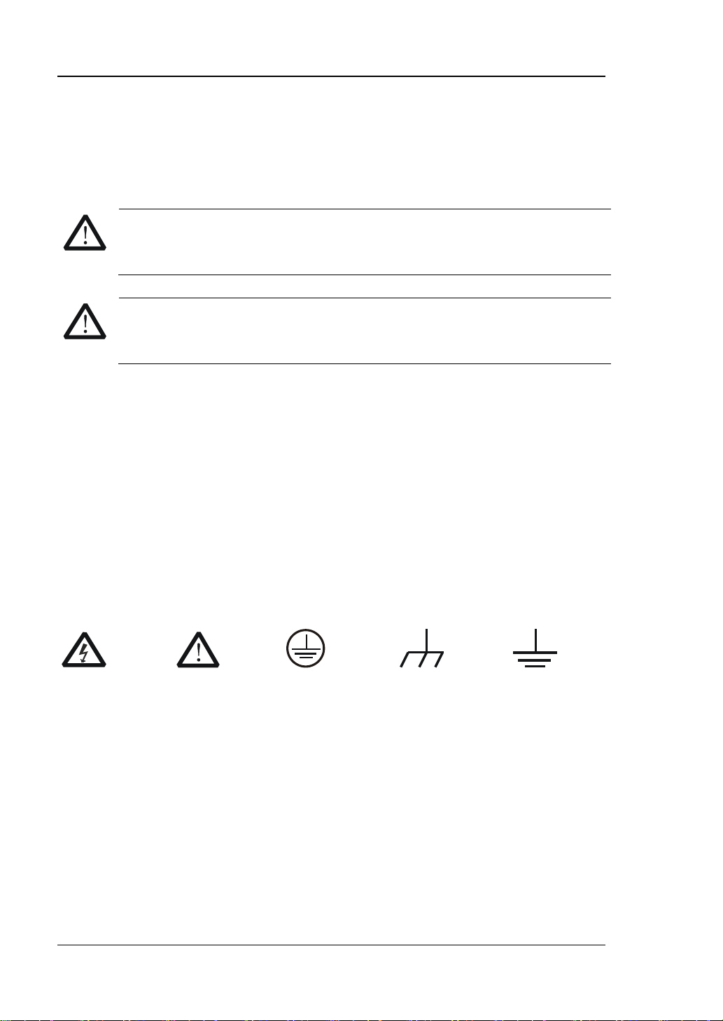
Safety Terms and Symbols
Terms Used in this Manual. These terms may appear in this manual:
WARNING
injury or loss of life.
Caution statements indicate the c onditions or practic es that coul d result i n
damage to this product or other property.
Terms Used on the Product. These terms may appear on the Product:
DANGER
WARNING indicates an injury or hazard may be accessible potentially.
CAUTION indicates potential damage to the instrument or other property might
Symbols Used on the Product. These symbols may appear on the product:
indicates an injury or hazard may immediately happen.
occur.
Voltage
Warning
Earth
Terminal
Ground
IV DG1000Z User’s Guide
Ground
Page 7

RIGOL
Allgemeine Sicherheits Informationen
Überprüfen Sie diefolgenden Sicherheitshinweise
sorgfältigumPersonenschädenoderSchäden am Gerätundan damit verbundenen
weiteren Gerätenzu vermeiden.Zur Vermeidung vonGefahren, nutzen Sie bitte das
Gerät nur so, wiein diesem Handbuchangegeben.
Um Feuer oder Verletzungen zu
vermeiden, verwenden Sie ein
ordnungsgemäßes Netzkabel
Verwenden Sie für dieses Gerät nur das
für ihr Land zugelassene und
genehmigte Netzkabel.
Erden des Gerätes
Das Gerät ist durch den Schutzleiter im
Netzkabel geerdet. Um Gefahren durch
elektrischen Schlag zu vermeiden, ist es
unerlässlich, die Erdung durchzuführen.
Erst dann dürfen weitere Ein- oder
Ausgänge verbunden werden.
Anschluss einesTastkopfes
Die Erdungsklemmen der Sonden
sindauf dem gleichen Spannungspegel
des Instruments geerdet. SchließenSie
die Erdungsklemmen an keine hohe
Spannung an.
Beachten Sie alle Anschlüsse
Zur Ve rm e idung von Feu er oder
Stromschlag, beachten Sie alle
Bemerkungen und Markierungen auf
dem Instrument. Befolgen Sie die
Bedienungsanleitung für weitere
Informationen, bevor Sie weitere
Anschlüsse an das Instrument legen.
Verwenden Sie einen geeigneten
Überspannungsschutz
Stellen Sie sicher, daß keinerlei
Überspannung (wie z.B. durch Gewitter
verursacht) das Gerät erreichen kann.
Andernfallsbestehtfür den Anwender
die GefahreinesStromschlages.
Nicht ohne Abdeckung einschalten
Betreiben Sie das Gerät nicht mit
entfernten Gehäuse-Abdeckungen.
Betreiben Sie das Gerät nic h t
geöffnet
Der Betrieb mit offenen oder entfernten
Gehäuseteilen ist nicht zulässig. Nichts
in entsprechende Öffnungen stecken
(Lüfter z.B.)
Passende Sicherung verwenden
Setzen Sie nur die
spezifikationsgemäßen Sicherungen
ein.
Vermeiden Sie ungeschützte
Verbindungen
Berühren Sie keine unisolierten
Verbindungen oder Baugruppen,
während das Gerät in Betrieb ist.
Betreiben Sie das Gerät nic h t i m
Fehlerfall
Wenn Sie am Gerät einen Defekt
vermuten, sorgen Sie dafür, bevor Sie
das Gerät wieder betreiben, dass eine
Untersuchung durch qualifiziertes
Kundendienstpersonal durchge führt
wird.Jedwede Wartun g , Einst ella rbeiten
oder Austausch von Teilen am Gerät,
sowie am Zubehör dürfen nur von
RIGOL autorisiertem Personal
durchgeführt werden.
DG1000Z User’s Guide V
Page 8

RIGOL
Belüftung sicherstellen
Unzureichende Belüftung kann zu
Temperaturanstiegen und somit zu
thermischen Schäden am Gerät führen.
Stellen Sie deswegen die Belüftung
sicher und kontrollieren regelmäßig
Lüfter und Belüftungsöffnungen.
Nicht in feuchter Umgebung
betreiben
Zur Vermeidung von Kurzschluß im
Geräteinneren und Stromschlag
betreiben Sie das Gerät bitte niemals in
feuchter Umgebung.
Nicht in explosiver Atmosphäre
betreiben
Zur Ve rm e idung von Pe rs onen- und
Sachschäden ist es unumgänglich, das
Gerät ausschließlich fernab jedweder
explosiven Atmosphäre zu betreiben.
Geräteoberflächen sauber und
trocken halten
Um den Einfluß von Staub und
Feuchtigkeit aus der Luft
auszuschließen, halten Sie bitte die
Geräteoberflächen sauber und trocken.
Schutz gegen elektrostatische
Entladung (ESD)
Sorgen S ie für eine elektrostatisch
geschützte Umgebung, um somit
Schäden und Funktionsstörun gen du r ch
ESD zu vermeiden. Erden Sie vor dem
Anschluß immer Innen- und Außenleiter
der Verbindungsleitung, um statische
Aufladung zu entladen.
Die richtige Verwendung desAkku.
Wenneine Batterieverwendet wird,
vermeiden Sie hohe Temperaturen bzw.
Feuer ausgesetzt werden.Bewahren Sie
es außerhalbder Reichweitevon Kindern
auf.UnsachgemäßeÄnderung
derBatterie(Anmerkung:Lithium-Batteri
e)kann zu einer Explosion führen.
VerwendenSie nur von
RIGOLangegebenenAkkus.
Sicherer Transport
Transportieren Sie das Gerät sorgfält ig
(Verpackung!), um Schäden an
Bedienelementen, Anschlüssen und
anderen Teilen zu vermeiden.
VI DG1000Z User’s Guide
Page 9
RIGOL
WARNING
Schäden oder den Tod von Personen zur Folge haben können.
CAUTION
Schäden am Gerät hervorrufen können.
DANGER (dt. GEFAHR)
weist auf eine V erletzung ode r Gefährdung hin ,
die sofort geschehen kann.
WARNING (dt. WARNUNG)
weist auf eine V erletzung ode r Gefährdung hin ,
CAUTION (dt. VORSICHT)
bedeutet, dass eine mögliche Beschädigung
auftre t e n kann.
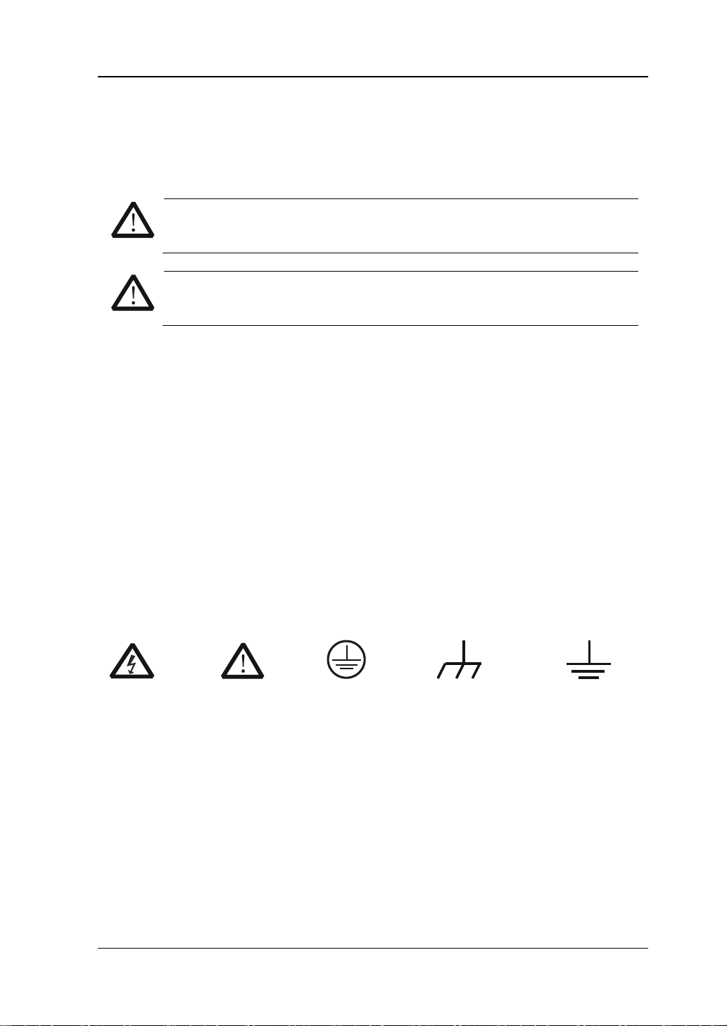
Sicherheits Begriffe und Symbole
Begriffe in diesem Guide. Diese Begriffe können in diesem Handbuch
auftauchen:
Die Kennzeichnung WARNING beschreibt Gefahrenque llen die leibliche
Die Kennzeichnung Caution (Vorsicht) beschreibt Gefahrenquellen die
Begriffe auf dem Produkt. Diese Bedingungen können auf dem Produkt
erscheinen:
die möglicherweise nicht sofort geschehen.
des Instruments oder anderer Gegenstände
Symbole auf dem Produkt. Diese Symbole können auf dem Produkt
erscheinen:
GefährlicheS
pannung
SicherheitsHinweis
Schutz-erde Gehäusemasse Erde
DG1000Z User’s Guide VII
Page 10
RIGOL
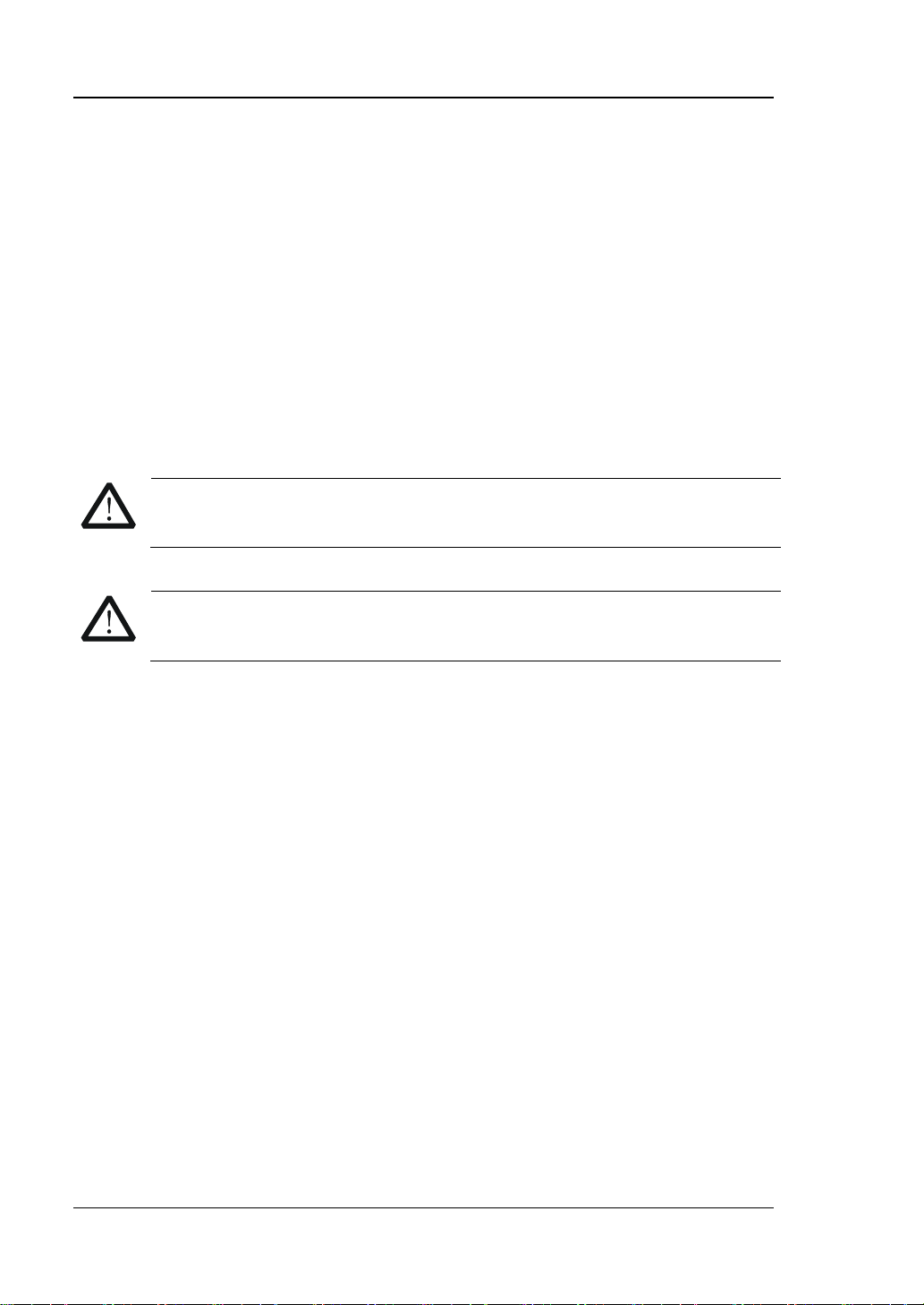
CAUTION
To avoid damages to the instrument, do not expose them to liquids which
have causticity.
WARNING
To avoid injury resulting from short circuit, make sure the instrument is
completely dry before reconnecting to a power source.
General Care and Cleaning
General Care:
Do not store or leave the instrument in where the instrument will be exposed to
direct sunlight for long periods of time.
Cleaning:
Clean the instrument regularly according to its operating conditions. To clean the
exterior surface, perform the following steps:
1. Disconnect the instrument from all power sources.
2. Clean the loose dust on the outside of the instrument with a lint - free clot h (with
a mild detergent or water). When cleaning the LCD, take care to avoid scarifying
it.
VIII DG1000Z User’s Guide
Page 11

RIGOL
Environmental Consideratio ns
The following symbol indicates that this product complies with the requirements in
WEEE Directive 2002/96/EC.
Product End-of-Life Handling
The equipment may contain substances t hat could b e ha rmful to the environ ment or
human health. In order to avoid release of such substances into the environment and
harm to human health, we encourage you to recycle this product in an appropriate
system that will ensure that most of the materials are reused or recycled
appropriately. Please contact your local authorities for disposal or recycling
information.
DG1000Z User’s Guide IX
Page 12

RIGOL
DG1000Z Series Overview
DG1000Z Series is a multifunctional gene r ator that combines many functions in one ,
including Function Generator, Arbitrary Waveform Generator, Noise Generator, Pulse
Generator, Harmonics Ge nerator, Analog/Digital Modulator and Counter. As a
multi-functional, high performance, high cos t -effective and portable gene rat or, it will
be a new selection in education, R&D, production, test, etc.
Main Features:
Maximum output frequency (Sine): 30MHz and 60MHz
Innovative SiFi (Signal Fidelity): generate the arbitrary waveform point by point,
undistortedly restore signal, precisely adjustable sample rate and low jitter
(down to 200ps) for all waveforms including Square, Pulse and etc.
Arbitrary wav e fo rm memory for each channel: 8Mpts (standard), 16Mpts
(optional)
Standard dual full functional channels which are equivalent to two independent
generators
±1ppm frequency stability, -125dBc/Hz phase noise
Built-in 8 orders harmonics generator
Built-in 7 digits/s full function frequency counter with 200MHz bandwidth
Up to 160 built-in waveforms encompassing common signals in various fields
including Engineering, Medical Elect ronics, Autom otive E lectronics, Mathemati cs
and etc.
200MSa/s sample rate, 14bits vertical resolution
Standard powerful arbitrary waveform editing function.
arbitrary waveform using PC software
Various modulation functions: AM, FM, PM, ASK, FSK, PSK and PWM
Standard waveform summing function. When it is enabled, you can superpose
specified waveform onto basic waveform before output
Standard channel tracking function. When it is enabled,
channels can be modified synchronously according to user’s requirements
Standard interfaces: US B Host, USB Device, LAN (LXI Core Device 2 011)
3.5 inches (320*240) color display
Portable design, only weight 3.5kg
Users can also edit
all parameters of dual
X DG1000Z User’s Guide
Page 13

RIGOL
Chapter 1 Qu ick Start
Briefly introduces the appearance and
of DG1000Z.
Chapter 2 Front Panel O perations
Introduce the main functions and operation
methods of DG1000Z.
Chapter 3 Remote Control
Briefly introduce how to control the DG1000Z
remotely.
Chapter 4 Troubleshooting
List the possible failures or problems and their
solutions when using DG1000Z.
Chapter 5 Specifications
Provide the specifications of DG1000Z series.
Chapter 6 Appendix
Provide the information about the options and
of DG1000Z.
Document Overview
Subjects in this Manual
dimensions, front/rear panel and user interface
accessories list as well as warranty information
Format Conventions in this Manual
1. Button:
The button at the front panel is denoted by the format of “Text Box + Button
Name (Bold)” in the manual, for example, Sine.
2. Menu:
The menu is denoted by the format of “Character Shading + Menu Word (Bold)”
in the manual, for example, Freq.
3. Connector:
The connector at the front or rear panel is denoted by the format of “Square
Brackets+Connector Name (Bol d)” in the manual, for example, [Counter].
4. Operation Steps:
The next step of the operation is denoted by an arrow “” in the manual. For
example, Sine Freq represents pressing Sine at the front panel and then
pressing Freq.
DG1000Z User’s Guide XI
Page 14

RIGOL
Model
Channels
Max. Frequency
DG1062Z
2
60MHz
DG1032Z
2
30MHz
Content Conventions in this Manual
1. DG1000Z series function/arbitrary waveform generator includes DG1032Z and
DG1062Z. In this manual, DG1062Z is taken as an example to introduce the
operating method of the generator.
2. Both models of DG1000Z series function/arbitrary waveform generator are
equipped with dual channels (CH1 and CH2). Unless otherwise specified, this
manual takes CH1 as an example to introduce the operation methods which are
also applied to CH2.
Manuals of this Product
The manuals of this product mainly include the quick guide, user’s guide,
programming guide and data sheet. For the newest version of the desired manual,
download it from the RIGOL website (www.rigol.com).
XII DG1000Z User’s Guide
Page 15

RIGOL
Contents
Guaranty and Declaration ......................................................................... I
Safety Requirement ................................................................................ II
General Safety Summary ........................................................................... II
Safety Terms and Symbols ....................................................................... IV
Allgemeine Sicherheits Informationen ......................................................... V
Sicherheits Begriffe und Symbole ............................................................. VII
General Care and Cleaning ..................................................................... VIII
Environmental Considerations ................................................................... IX
DG1000Z Series Overview ........................................................................ X
Document Overview ............................................................................... XI
Chapter 1 Quick Start ......................................................................... 1-1
General Inspection ................................................................................ 1-2
To Adjust the Handle ............................................................................. 1-3
Appearance and Dimensions ................................................................... 1-4
Front Panel Overview ............................................................................. 1-5
Rear Panel Overview ............................................................................. 1-11
Power On and Inspection ...................................................................... 1-14
To Connect to Power ...................................................................... 1-14
Power-on ...................................................................................... 1-14
To Set the System Language ........................................................... 1-15
User Interface ...................................................................................... 1-16
Dual Channels Parameters Mode ..................................................... 1-16
Dual Channels Graph Mode ............................................................. 1-19
Single Channel View Mode .............................................................. 1-19
To Use the Built-in Help System ............................................................. 1-20
Rack Mount Kit Installation (Option) ....................................................... 1-21
To Install Single Instrument ............................................................ 1-21
To Install Dual Instruments ............................................................. 1-26
Chapter 2 Front Panel Operations ...................................................... 2-1
To Output Basic Waveform ..................................................................... 2-2
To Select Output Channel ................................................................ 2-2
To Select Basic Waveform ................................................................ 2-3
To Set Frequency/Perio d .................................................................. 2-4
To Set Amplitude/High Level ............................................................ 2-5
To Set Offset/Low Level ................................................................... 2-7
To Set Start Phase .......................................................................... 2-8
Align Phase .................................................................................... 2-9
To Set Duty Cycle (Square) ............................................................. 2-10
To Set Symmetry (Ramp) ................................................................ 2-11
To Set Pulse Width/Duty Cycle (Pulse) ............................................. 2-12
DG1000Z User’s Guide XIII
Page 16

RIGOL
To Set Leading/Trailing Edge Time (Pulse) ........................................ 2-13
To Enable Output ........................................................................... 2-14
Example: To Output Sine Waveform ................................................ 2-15
To Output Arbitrary Waveform ............................................................... 2-17
To Enable Arbitrary Wavef o rm ......................................................... 2-17
Output Mode and Sample Rate ....................................................... 2-18
To Select Arbitrary Waveform .......................................................... 2-19
To Edit Arbitrary Waveform ............................................................. 2-26
To Output Harmonic ............................................................................. 2-30
Overview ...................................................................................... 2-30
To Set Fundam e nt a l Waveform Parameters ...................................... 2-31
To Set Harmonic Order ................................................................... 2-31
To Select Harmonic Type ................................................................ 2-31
To Set Harmonic Amplitude............................................................. 2-32
To Set Harmonic Phase .................................................................. 2-32
Example: To Output Harmonic ........................................................ 2-33
Modulation .......................................................................................... 2-35
Amplitude Modulation (AM) ............................................................ 2-35
Frequency Modulation (FM) ............................................................ 2-39
Phase Modulation (PM) .................................................................. 2-42
Amplitude Shift Keying (ASK) .......................................................... 2-45
Frequency Shift Keying (FSK) .......................................................... 2-48
Phase Shift Keying (PSK) ................................................................ 2-51
Pulse Width Modulation (PWM) ....................................................... 2-54
Sweep................................................................................................. 2-57
To Enable Sweep Function .............................................................. 2-57
Start Frequency and St op Fr equ e n cy ............................................... 2-57
Center Frequency and Frequency Span ............................................ 2-58
Sweep Type .................................................................................. 2-59
Sweep Time .................................................................................. 2-60
Return Time .................................................................................. 2-60
Mark Frequency ............................................................................. 2-61
Start Hold ..................................................................................... 2-61
Stop Hold ..................................................................................... 2-62
Sweep Trigger Source .................................................................... 2-62
Burst .................................................................................................. 2-65
To Enable Burst Function ................................................................ 2-65
Burst Type .................................................................................... 2-65
Burst Period .................................................................................. 2-67
Gated Polarity ............................................................................... 2-67
Burst Delay ................................................................................... 2-68
Burst Trigger Source ...................................................................... 2-68
Counter ............................................................................................... 2-70
To Enable the Counter .................................................................... 2-70
To Set the Counter ......................................................................... 2-71
Store and Recall ................................................................................... 2-74
XIV DG1000Z User’s Guide
Page 17

RIGOL
Storage System ............................................................................. 2-74
File Type ....................................................................................... 2-75
Browser Type ................................................................................ 2-77
File Operation ................................................................................ 2-77
Seamless Interconnection with Oscilloscope ..................................... 2-81
Utility and System Settings .................................................................... 2-83
Channel Set................................................................................... 2-84
Coupling Set .................................................................................. 2-90
Channel Copy ................................................................................ 2-93
Restore Default .............................................................................. 2-94
To Set System Languege ................................................................ 2-99
System Informat i on ........................................................................ 2-99
System Set .................................................................................. 2-100
I/O Configuration ......................................................................... 2-103
Print Set ..................................................................................... 2-108
Test/Calibration............................................................................ 2-108
To Use External Power Amplifier (Option) ....................................... 2-109
Chapter 3 Remote Control .................................................................. 3-1
Remote Control via USB ......................................................................... 3-2
Remote Control via LAN ......................................................................... 3-5
Remot e Control via GPIB (Option) ........................................................... 3-8
Chapter 4 Troubleshooting ................................................................. 4-1
Chapter 5 Specifications ..................................................................... 5-1
Chapter 6 Appendix ............................................................................ 6-1
Appendix A: Accessories and Options ...................................................... 6-1
Appendix B: Specifications of Power Amplifier .......................................... 6-2
Append i x C: Warranty ............................................................................ 6-4
Index ....................................................................................................... 1
DG1000Z User’s Guide XV
Page 18

Page 19

Chapter 1 Quick Start RIGOL
Chapter 1 Quick Start
This chapter briefly introduces the appearance and dimensions, front/rear panel and
user interface of DG1000Z as well as how to install the instrument into standard
cabinet.
Subjects in this chapter:
General Inspection
To Adjust the Handle
Appearance and Dimensions
Front Panel Overview
Rear Panel Overview
Power On and Inspection
User Interface
To Use the Built-in Help System
Rack Mount Kit Installation (Option)
DG1000Z User’s Guide 1-1
Page 20

RIGOL Chapter 1 Quick Start
General Inspection
1. Inspect the shipping container for damage.
Keep the damaged shipping container or cushioning material until the contents
of the shipment have been checked for completeness and the instrument has
passed both electrical and mechanical test.
The consigner or carrier shall be liable for the damage to instrument resulting
from shipment. RIGOL would not be re sponsible for free maintenance /rework
or replacement of the unit.
2. Inspect the instrument.
In case of any mechanical damage or defect, or if the instrument does not
operate properly or pass the electrical and mechanical tests, contact your local
sales representative of RIGOL.
3. Check the accessories.
Please check the accessories according to the packing lists. If the accessories
are incomplete or damaged, please contact your RIGOL sales representative.
1-2 DG1000Z User’s Guide
Page 21
Chapter 1 Quick Start RIGOL
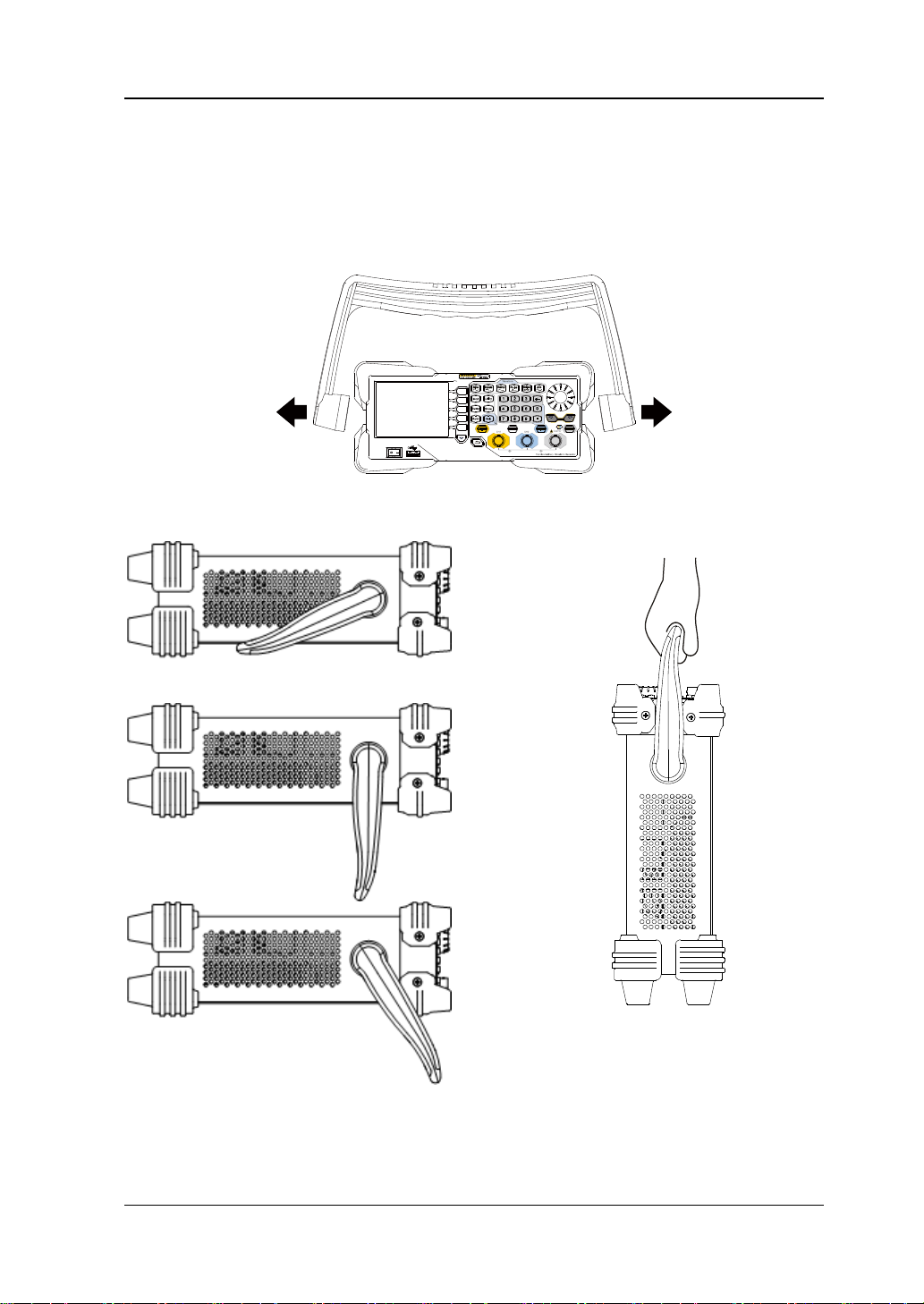
To Adjust the Handle
To adjust the handle, please hold the handle by sides of the instrument and pull it
outward, and then rotate the handle to the desired position (as shown in the figure
below).
Adjusting the Handle
Viewing Positions Move Position
DG1000Z User’s Guide 1-3
Page 22
RIGOL Chapter 1 Quick Start
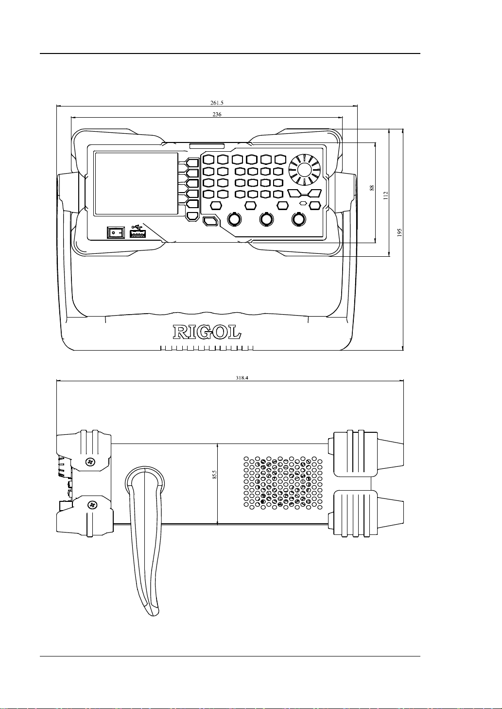
Appearance and Dimensions
Front View Unit: mm
Side View Unit: mm
1-4 DG1000Z User’s Guide
Page 23
Chapter 1 Quick Start RIGOL
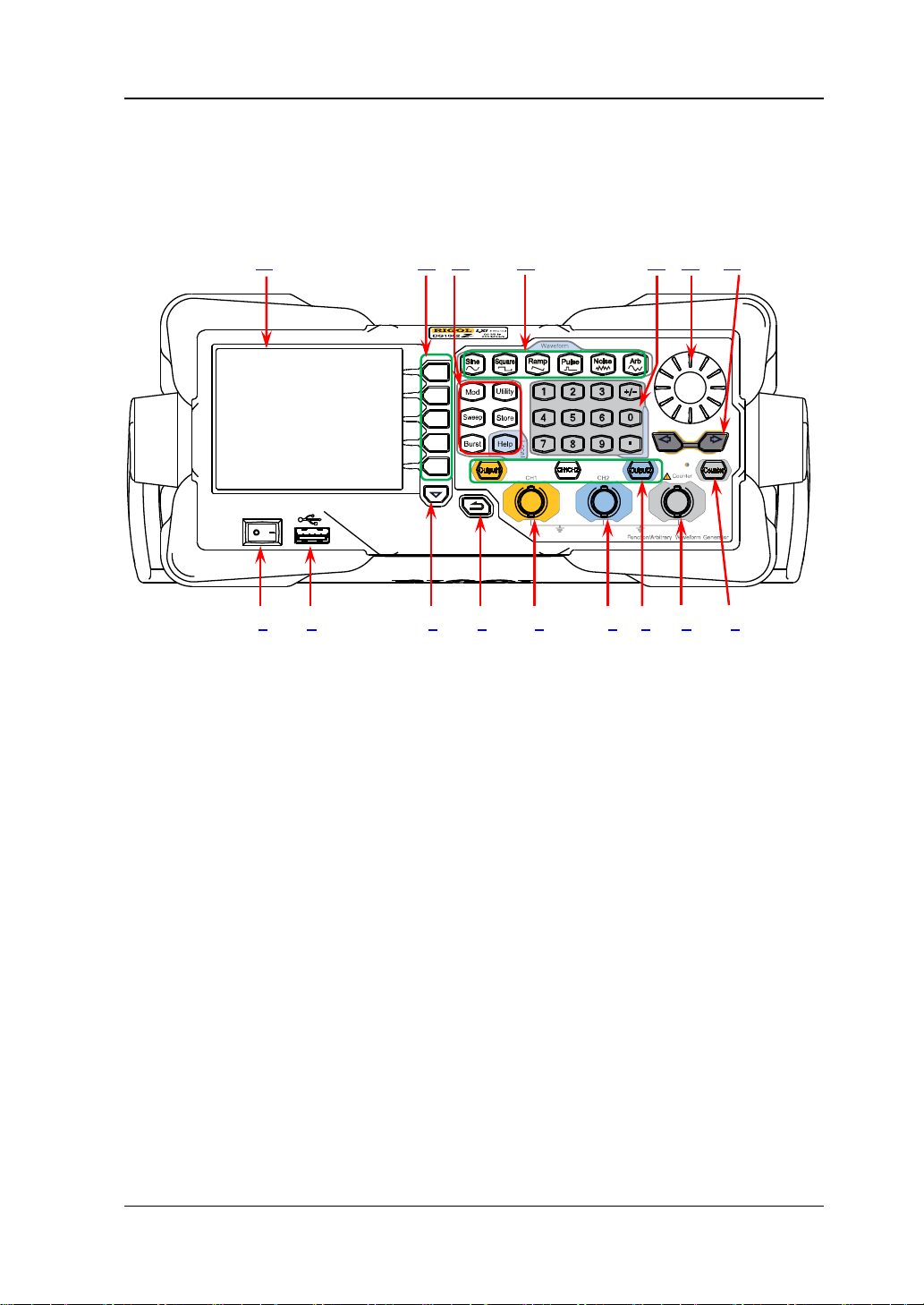
Front Panel Overview
The front panel of DG100 0Z is shown below. Click the numbers in the figure to view
the correspondin g de s cription.
16 15 14 13 12 11 10
1 2 3 4 5 6 7 8 9
Figure 1-1 Front Panel
1. Power Key
The power key is used to turn the generator on or off.
2. USB Host
Support USB storage device, RIGOL TMC digital oscilloscope (DS), power
amplifier (PA) and USB to GPIB interface converter (Option).
USB storage device: read the waveform or state files saved in the USB
storage device or store the current instrument states or e dited wave form
data into the USB storage device. In additional, the content displayed on
the screen also can be saved as a picture file (*.Bmp) into the USB storage
device.
TMC DS: seamlessly interconnect with the RIGOL DS that meets th e TM C
standard. R ead and store the wav eform data collected by the DS and rebuilt
waveform losslessly.
PA (option): support the RIGOL power amplif ier (such as PA1011). You
can configure it online and the signal is outputted after whose power is
amplified.
USB to GPI B interface converter (Option): expand the GPIB interface for
RIGOL instrument with USB Host interface but without GPIB interface.
DG1000Z User’s Guide 1-5
Page 24
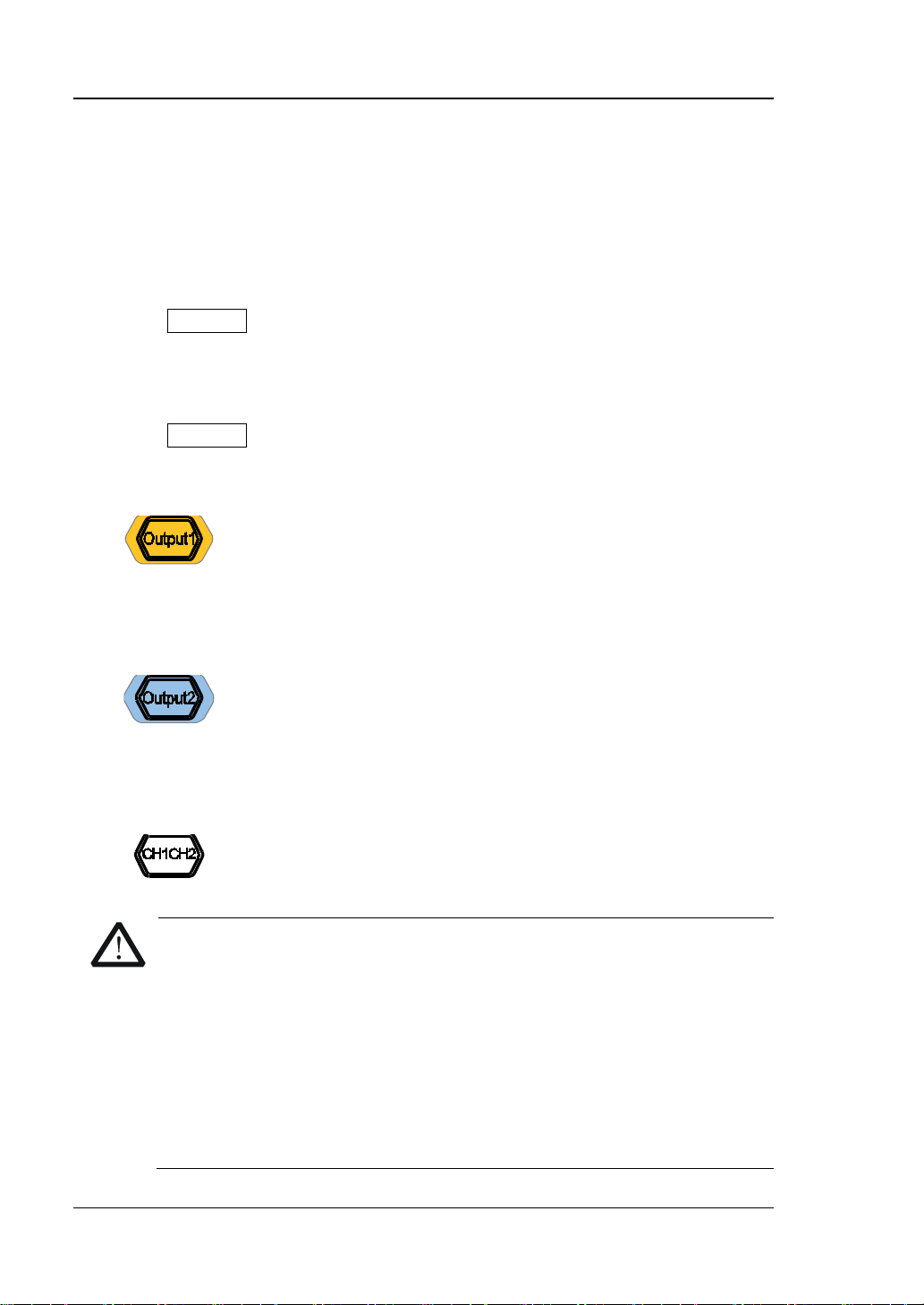
RIGOL Chapter 1 Quick Start
It is used to control the output of CH1.
It is used to control the output of CH2.
It is used to switch the current selected channel between CH1
CAUTION
voltage is greater than ±3.5×(1±5%)V (<10kHz).
3. Page Up/Down
Open the next page of the current function menu or return to the first page.
4. Return to the Previous Menu
Exit the current menu and return to the previous menu.
5. CH1 Output Connector
BNC connector with 50Ω nominal output impedance.
When Output1 is enabled (the backlight turns on), this connector outputs
waveform according to the current configuration of CH1.
6. CH2 Output Connector
BNC connector with 50Ω nominal output impedance.
When Output2 is enabled (the backlight turns on), this connector outputs
waveform according to the current configuration of CH2.
7. Channels Control Area
— Press this key to open the output of CH1, the backlight turns
on and the [CH1] connector outputs the waveform
according to the current configuration of CH1.
— Press this key again to close the output of CH1 and the
backlight turns off.
— Press this key to open the output of CH2, the backlight turns
on and the [CH2] connector outputs the waveform
according to the current configuration of CH2.
— Press this key again to close the output of CH2 and the
backlight turns off.
and CH2.
Overvoltage protection of the output channels of CH1 and CH2 will take
effect once any of the foll owing conditions is met. When the overvoltage
protection takes effect, the prompt message will be displayed on the
screen and the output will be disabled.
The amplitude setting in the generator is greater than 2Vpp or the
output offset is greater than |2V
|, the input voltage is greater than
DC
±11.5×(1±5%)V (<10 kHz).
The amplitude setting in the generator is lower than or equal to
2Vpp or the output offset is lower than or equal to |2V
1-6 DG1000Z User’s Guide
|, the input
DC
Page 25
Chapter 1 Quick Start RIGOL
CAUTION
exceed ±7Vac+dc.
8. Input Connector for the Signal Measured by Counter
BNC connector with 1MΩ input impedance. It is used to accept the signal
measured by the counter.
To avoid damag es to the instrument, the input signal voltage can not
9. Counter
It is used to turn the counter on or off.
— Press this key to turn the counter on, the backlight turns on and the
indicator at the left of Counter blinks.
— Press this key again to turn the counter off and the backlight turns off.
Note: the sync signal of CH2 will be disabled if the counter is turned on and it
will be enabled after the counter is turned off.
10. Direction Keys
— Used to move the cursor to select the digit to be edited when setting
paramete r u sing knob.
— Used to delete the number at the left of the cursor when inputting
parameter using numeric keyboard.
— Used to unfold or fold the current selected directory when storing or
reading file.
— Used to move the cursor to select the specified character in filename input
area when editing filename.
11. Knob
— Used to increase (clockwise) or decrease (counterclockwise) the value
marked by the cursor when setting para met er using kno b .
— Used to select the s torage location when storing a file or used to sele ct t he
file to be read when reading file.
— Used to select a character fr om the virtual ke yboard when editing filename.
— Used to select a desired built-in arbitrary wavefo rm from Arb Select
Wform BuiltIn.
12. Numeric Keyboard
It consists of numbers (0 to 9), decimal point (.), sign key (+/-) and is used to
set parameters.
Note:
1) The sign key is used to switch between uppercase and lowercase when
editing filename.
2) Use the decimal point key to quickly save the content displayed in the user
interface in the USB storage device in *.Bmp format (for the detailed steps,
please refer to “Print Set ”).
DG1000Z User’s Guide 1-7
Page 26
RIGOL Chapter 1 Quick Start
Output Sine with frequency from 1μHz to 60MHz.
Output Squa re with frequency f rom 1μHz to 25MHz and v ariable
Output Ramp with frequency from 1μHz to 1 MHz and variable
Output Pulse with frequency from 1μHz to 25MHz and variable
Output Gauss Noise with 60MHz bandwidth.
Output Arbitrary waveform with frequency from 1μHz to 20MHz.
Freq/Period, Ampl/HiLevel, Offset/LoLevel and
13. Waveforms Key
— The backlight turns on when this function is selected.
— You can set Freq/Period, Ampl/HiLevel, Offset/LoLevel and
Start Phase of sine waveform .
duty cycle.
— The backlight turns on when this function is selected.
— You can set Freq/Pe ri od, Ampl/HiLe vel, Offset /LoLevel,
Duty Cycle and Start Phase of square wavefo rm.
symmetry.
— The backlight turns on when this function is selected.
— You can set Freq/Period, Ampl/HiLevel, Offset/LoLevel,
Symmetry and Start Phase of ramp waveform.
pulse width and edge time.
— The backlight turns on when this function is selected.
— You can set Freq/Period, Ampl/HiLevel, Offset/LoLevel,
Width/Duty, Leading, Trailing and Start Phase of pulse
waveform.
— The backlight turns on when this function is selected.
— You can set Ampl/HiLevel and Offset/LoLevel of Noise.
— Support Sample Rate and Frequency output modes.
— Up to 160 built-in waveforms and support powerful
arbitrary waveform editing function.
— The backlight turns on when this function is selected.
— You c a n set
Start Phase of arbitrary waveform.
1-8 DG1000Z User’s Guide
Page 27
Chapter 1 Quick Start RIGOL
Output multiple types of modulated wavefo rms.
Output sweep waveform for Sine, Square, Ramp and Arb
Output Burst waveform for Sine, Squa r e, Ramp, Pulse and Arb
Used to set the auxiliary function parameters and system
The backlight turns on when this function is
Store or recall the inst rument state o r the user-defined arbitra ry
A nonvolatile memory (C disk) is built in and a USB st orage
To get the help information of any front panel key or menu
14. Function keys
— Support multiple modulation types: AM, FM, PM, ASK, FSK,
PSK and PWM.
— Support internal and external modulation sources.
— The backlight turns on when this function is selected.
(except DC).
— 3 sweep types: Linear, Log and Step.
— 3 types of trigger sources: Internal, External and Manual.
— Provide frequency mark function used to control the status
of the sync signal.
— The backlight turns on when this function is selected.
(except DC).
— 3 burst types: NCycle, Inf inite and Gated.
— Noise can also be used to generate Gated Burst.
— 3 types of trigger sources: Internal, External and Manual.
— The backlight turns on when this function is selected.
parameters.
selected.
waveform data.
—
device (D disk) can be connected.
— The backlight turns on when this function is selected.
softkey, press this key and then press the desired key.
Note:
1) When the instrument is working in remote mode, press this
key to return to local mode.
2) Used to lock or unlock the keyboard . Pres s and hold Help
to lock the front panel keys and at this point, the front panel
keys (except Help) are not available. Press and hold this
key agai n t o unlock.
DG1000Z User’s Guide 1-9
Page 28

RIGOL Chapter 1 Quick Start
15. Menu Softkeys
Correspond to the left displayed menus respectively. Press this softkey to
activate the corresponding menu.
16. LCD
3.5 inches TFT (320×240) color LCD display. The curre nt function menu,
settings, system state as well as prompt messages and etc. ca n be clearly
displayed (for the detailed information, refer to “User Interface”).
1-10 DG1000Z User’s Guide
Page 29
Chapter 1 Quick Start RIGOL
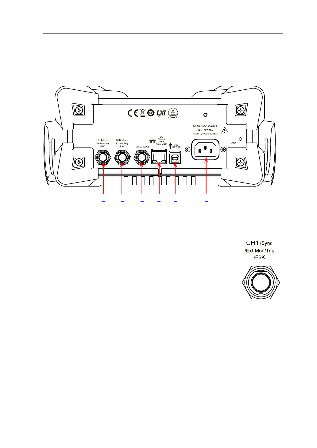
Rear Panel Overview
The rear panel of DG1000Z is as shown in the figure below. Click the numbers in the
figure to view the corresponding description.
1 2 3 4 5 6
Figure 1-2 Rear Panel
1. [CH1/Sync/Ext Mod/Trig/FSK]
BNC female connector with 50Ω nominal impedance.
Its function is determined by the current work mode of CH1.
1) Sync
When the output of CH1 is enable d, this connector outputs
the corresponding sync signal. For detailed information
about the characteristics of the sync signals corresponding
to various output si gnals, ref er to the int roduction in “Sync
Set”.
2) Ext Mod
When AM, FM, PM or PWM of CH1 is enabled and external modulation
source is selected, this connector accepts an external modulati on signal and
the input impedance is 1000Ω. For the detailed introduction, refer to
“Modulation”.
3) FSK
When ASK, FSK or PSK of CH1 is enabled and external modulation sou rce is
selected, this connector accepts an external modulation signal whose
polarity can be set by users and the input impedance is 1000Ω. For the
detailed introduction, refer to “Modulation”.
DG1000Z User’s Guide 1-11
Page 30
RIGOL Chapter 1 Quick Start
4) Trig In
When Sweep or Burst of CH1 is enabled and external trigger source is
selected, this connector accepts an external trigger signal whose polarity
can be set by users.
5) Trig Out
When Sweep or Burst of CH1 is enabled and internal or manual trigger
source is selected, this connector outputs a trigger signal with specified
edge type.
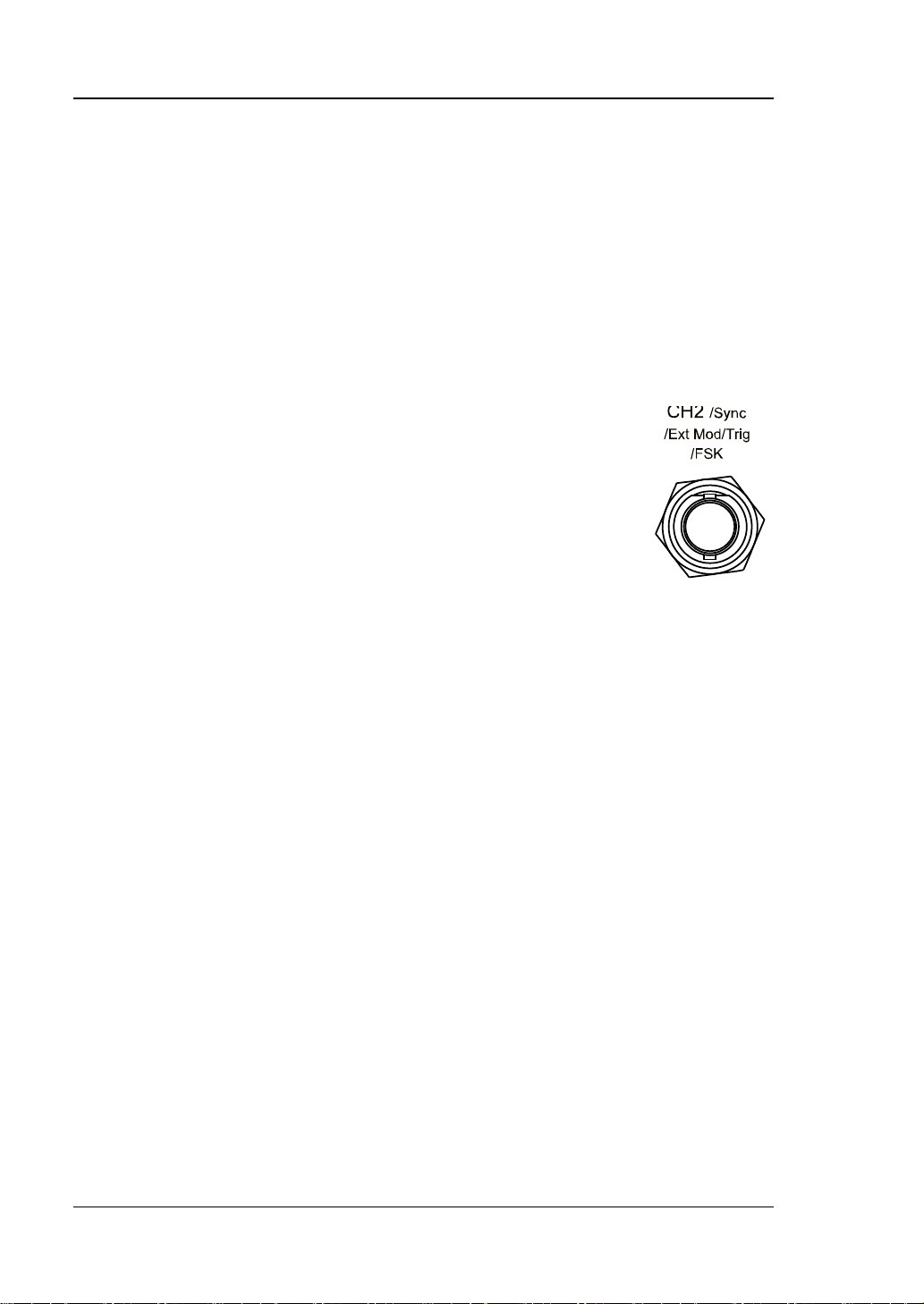
2. [CH2/Sync/Ext Mod/Trig/FSK]
BNC female connector with 50Ω nominal impedance.
Its function is determined by the current work mode of CH2.
1) Sync
When the output of CH2 is enable d, this connector outputs
the corresponding sync signal. For detailed information
about the characteristics of the sync signals corresponding
to various output s ignals, r efe r to the int rodu ction in “Sync
Set”.
2) Ext Mod
When AM, FM, PM or PWM of CH2 is enabled and external modulation
source is selected, this con nector accepts an external modulation signal an d
the input impedance is 1000Ω. For the detailed introduction, refer to
“Modulation”.
3) FSK
When ASK, FSK or PSK of CH2 is enabled and externa l modulation s ource is
selected, this connector accepts an external modulation signal whose
polarity can be set by users and the input impedance is 1000Ω. For the
detailed introduction, refer to “Modulation”.
4) Trig In
When Sweep or Burst of CH2 is enabled and external trigger source is
selected, this connector accepts an exter nal trigger sig nal whose polarity
can be set by users.
5) Trig Out
When Sweep or Burst of CH2 is enabled and internal or manual trigger
source is selected, this connector outputs a trigger signal with specified
edge type.
1-12 DG1000Z User’s Guide
Page 31

Chapter 1 Quick Start RIGOL
Used to connect the generator to you r comp ute r or th e
Used to connect the generator to a compute r which can
The AC power supply specif ic ation of this signal
3. [10MHz In/ Out]
BNC female connector with 50Ω nominal impedance.
The function of this connector is determined by the type of the
clock source.
1) When internal clock source is selected, this connector (as
10MHz Out) outputs the 10MHz clock signal generated by
the internal crystal oscillator inside the generator.
2) When external clock source is selected, this connector (as 10MHz In)
accepts an external 10MHz clock signal.
This connector is typically used to synchronize multiple instruments. For more
detailed information about the signals mentioned above, please refer to the
introduction in “Clock Source”.
4. LAN
network of your computer for remote control. An
integrated testing system may be built, as the generator
conforms to the LXI Core Device 2011 class standard of
LAN-based instrument con t rol.
5. USB Device
control the generator remotely using PC software or b y
programming. It can also be connected to a PictBridge
printer to print the contents displayed in the screen.
6. AC Power Input
generator is 100-240V, 45-440Hz. The maximum input
power of the instrument cannot exceed 30W. The
specif ication of the fuse is 250V, T3.15A.
DG1000Z User’s Guide 1-13
Page 32

RIGOL Chapter 1 Quick Start
CAUTION
grounded.
Power On and Inspection
To Connect to Power
Please connect the generator to AC power supply using the power cord supplied in
the accessories (as shown in the figure below). The AC power supply spe cification of
this generator is 100-240V, 45-440Hz. The maximum input power of the instrument
cannot exceed 30W. W hen the signal generato r is connected to AC powe r s up p ly via
this connector, the instrument adjusts itself to select the correct voltage range
automatically and users do not need to select the voltage range manually.
Power-on
After the power s upply is c orrectly connected, press the power key
panel to turn on the generator. During the start-up, the instrument executes
initialization and self-test. After that, the default interface is displayed. If the
instrument does not start normally, please refer to the introduction in
“Troubleshooting”.
1-14 DG1000Z User’s Guide
Figure 1-3 Connect to Power
To avoid electric shock, make sure that the instrument is correctly
at the front
Page 33

Chapter 1 Quick Start RIGOL
To Set the System Language
DG1000Z series supports Chinese and English system languages. You can press
Utility Language to select the desired system language.
DG1000Z User’s Guide 1-15
Page 34

RIGOL Chapter 1 Quick Start
7
8
9
10
Type of Output Impedance:
Channel Output
Selected
Type of Modulation
Work Mode:
Modulating waveform of Anal og Modulation:
User Interface
DG1000Z user interface includes three types of display modes: Dual Channels
Parameters (default), Dual Channels Graph and Single Channel View. In thi s
manual, the Dual Channels Parameters display mode is mainly taken as an
example to introduct the user interface.
Dual Channels Parameters Mode
6 5 4 3
Figure 1-4 User Interface (Dual Channels Parameters Mode)
1. Channel Output Configuration Status Bar
Display the current output configurations of the two channels.
AM/FM/PM/ASK/FSK/PSK/
PWM/Sweep/Burst
Waveform:
Sine
Squ
Ramp
Pulse
Noise
Arb
Harm
Source: Int/Ext
Type of Sweep/Burst Trig
Source: Int/Ext/Mu
Waveform Summing: Sum
1-16 DG1000Z User’s Guide
1 2
Sine/Square/Tria/UpRamp/DnRamp/Noise/Arb
Polarity of Digital Modulation: Pos/Neg
Type of Sweep: Linear/Log/Step
Type of Burst: Ncycle/Infinite/Gated
State: ON/OFF
High impedance: display HighZ
Load: display impedance (the
default is 50Ω and the range i s
from 1Ω to 10KΩ)
Page 35

Chapter 1 Quick Start RIGOL
2. Current Function and Page Up/Down Indicator
Display the name of the function selected currently. For example, “Sine” is
displayed when the sine is selected and “Edit” is displ ayed when the arbitrary
waveform editing function is selected. Besides, th e up and down arrows at the
right of the function name are used to indicate whether page up/down is
permitted now.
3. Menu
Display the operation menu of the function selected currently.
4. Status Bar
: displayed when the instrument is connected into LAN correctly.
: displayed when the instrument is in remote mode.
: displayed when the front panel of the instrument is locked.
: displayed when a USB stora ge device is detected.
: displayed when the instrument is connected with power amplifier correctly .
5. Waveform
Display the wavef orm currently selected in each channel.
6. Channel Status Bar
Used to indicate the selected status and on/off status of the channels. When
CH1 is selected, the border of the bar is displayed in yellow. When CH2 is
selected, the border of the bar is displayed in blue. When the output of CH1 is
enabled, the “CH1” in the bar is hi ghlighted in y ellow . When t he output of CH2 is
enabled, the “CH2” in the bar is highlighted in blue.
Note: you can enable the outputs of the two channe ls but you cannot select the
two channels at the same time.
7. Frequency
Display the wavef orm frequency of the channel. P ress Freq/Period to highlight
“Freq” and use the numeric keyboard or direction keys a nd k no b to mo di fy t his
parameter.
8. Amplitude
Display the waveform amplitude of the channel. Press Ampl/HiLevel to
highlight “Ampl” and use the numeric keyboard or direction keys and knob t o
modify this parameter.
DG1000Z User’s Guide 1-17
Page 36

RIGOL Chapter 1 Quick Start
9. Offset
Display the waveform DC offset of the channel. Press Offset/LoLevel to
highlight “Offset” and use th e numeric keybo ard or direct ion keys and knob to
modify this parameter.
10. Phase
Display the waveform start phase of the channel. Press Start Phase and use
the numeric keyboard or direction keys and knob to modify this parameter.
1-18 DG1000Z User’s Guide
Page 37

Chapter 1 Quick Start RIGOL
Dual Channels Graph Mode
Press Utility System Display DispMod to select “Dual Graph”, as shown
in the figure below.
Figure 1-5 User Interface (Dual Channels Graph Mode)
Single Channel View Mode
Press Utility System Display DispMode to select “Single View”, as shown
in the figure below.
Figure 1-6 User Interface (Single Channel Mode)
DG1000Z User’s Guide 1-19
Page 38

RIGOL Chapter 1 Quick Start
To Use the Built-in Help System
DG1000Z built-in help system provides help information for each key and menu
softkey at the fron t pan el. When operating the instrument, users ca n view the help
information of any key at any time.
1. Acquire the built-in help
Press Help and the backlight turns on. Then press th e desired ke y or menu
softkey and the corresponding help information is displayed.
2. Page Up/Down
When the help information is display ed in multiple pages, users can acquire the
help information on the previous or next page using
line)/
3. Close the current help information
When help information is displayed in the interface, pressing
panel, the help information interface is closed and the interface before entering
the built-in help system is displa y ed.
4. Common help topics
Press Help twice to o pen the com mon help topics list. Use
the knob to select the desired help topic and press Select to view the
corresponding help information.
(the next line)/ (page up)/ (page down) or the knob.
(the previous
at the front
/ / / or
1-20 DG1000Z User’s Guide
Page 39

Chapter 1 Quick Start RIGOL
No.
Name
Qty
Description
Front Filler Panel
1
Fixing Part
1
③
M4 Screw
4
M4×8 Cross Recessed Pan Head Screw
M6 Screw
4
M6×16 Phil-Slot Pan Head Screw
M6 Nut
4
M6×5 Lock Blade Square Nut
Rack Mount Kit Installat ion (O ption )
To install this instrument into a standard 19 inches c abinet, please order rack mount
kit RM-1-DG1000Z (for installing single instrument) or RM-2-DG1000Z (for installing
dual instruments) and correctly install them according to this section.
Figure 1-7 Rack Mount Kit (RM-1-DG1000Z)
Figure 1-8 Rack Mount Kit (RM-2-DG1000Z)
To Install Single Instrument
Kit Parts List
Table 1-1 RM-1-DG1000Z Kit Parts List
①
②
④
⑤
DG1000Z User’s Guide 1-21
Page 40

RIGOL Chapter 1 Quick Start
(a)
③ ④ ⑤
(b)
Figure 1-9 RM-1-DG1000Z Kit Pa rts
1-22 DG1000Z User’s Guide
Page 41

Chapter 1 Quick Start RIGOL
Installation Tool
PH2 Phillips Screwdriver (recommended).
Installation Space
The following requirements must be fulfilled by the machine cabinet in which the
instrument is mounted.
The machine cabinet must be a standard 19-inch one.
At least 2U (88 mm) space should be provided by the machine cabinet.
The depth inside the machine cabinet should not be less than 300.2 mm.
The dimension of the instrument after being installed is as shown below.
DG1000Z User’s Guide 1-23
Page 42

RIGOL Chapter 1 Quick Start
CAUTION
installation might result in damage of the instrument or incorrect
installation of the instrument on the rack.
Installation Procedu re
Only authorized oper ator ca n execute the installation oper ation. Im prope r
1. First remove the handles of the instrument (hold the handles by s ides of th e
instrument and pull them outward). A nd then remove the four rubber pads at
the front and rear panel of the instrument respectively.
2. Fix the fixing part on one side of the front panel of t he inst rument using two M4
screws.
3. Fix the front filler panel on the other side of the front panel of the instrument
using two M4 screws.
1-24 DG1000Z User’s Guide
Page 43

Chapter 1 Quick Start RIGOL
4. Mount the rack with the instrument fixed to it into a standard 19-inch machine
cabinet with four M6 screws and four M6 square nuts.
5. The f igure of th e single instrument after being installed corre ctly is as shown
below.
DG1000Z User’s Guide 1-25
Page 44

RIGOL Chapter 1 Quick Start
No.
Name
Qty
Description
Fixing Part
2
Connector A
1
③
Connector B
1
Tail Connector
2
M4 Screw
4
M4×8 Cross Recessed Countersunk Head Screw
M4 Screw
8
M4×8 Cross Recessed Pan Head Screw
M6 Screw
4
M6×16 Phil-Slot Pan Head Screw
M6 Nut
4
M6×5 Lock Blade Square Nut
To Install Dual Instruments
Kit Parts List
Table 1-2 RM-2-DG1000Z Kit Parts List
①
②
④
⑤
⑥
⑦
⑧
1-26 DG1000Z User’s Guide
(a)
Page 45

Chapter 1 Quick Start RIGOL
⑤ ⑥ ⑦ ⑧
(b)
Figure 1-10 RM-2-DG1000Z Kit Parts
Installation Tool
PH2 Phillips Screwdriver (recommended).
Installation Space
The following requirements must be fulfilled by the machine cabinet in which the
instrument is mounted.
The machine cabinet must be a standard 19-inch one.
At least 2U (88 mm) space should be provided by the machine cabinet.
The depth inside the machine cabinet should not be less than 300.2 mm.
DG1000Z User’s Guide 1-27
Page 46

RIGOL Chapter 1 Quick Start
The dimensions of the instruments after being installed are as shown below.
1-28 DG1000Z User’s Guide
Page 47

Chapter 1 Quick Start RIGOL
CAUTION
installation might result in damage of the instrument or incorrect
installation of the instrument on the rack.
Installation Procedu re
Only authorized oper ators can exe cute the installatio n operation. Improper
1. First remove the handles of the two instruments (hold the handles by sides of
the instrument and pull them outward). And then remove the four rubber pads
on the front and rear panel of the two instruments respectively.
2. Fix one fixing part on the right side of the front panel of the instrument A using
two M4 cross recessed pan head screws. Fix the connector A on the left side of
the front panel of the instrument A using t wo M4 cross recessed countersunk
head screws.
DG1000Z User’s Guide 1-29
Page 48

RIGOL Chapter 1 Quick Start
3. Fix the other f ixing part on the left side of the fro nt panel of the instrument B
using two M4 cross recessed pan head screws. Fix the connector B on the right
side of the front panel of the instrument B using two M4 cross recessed
countersunk head screws.
4. Connect the connector A and B.
1-30 DG1000Z User’s Guide
Page 49

Chapter 1 Quick Start RIGOL
5. Fix the two tail connectors at the connection of the rear panel of the two
instruments respectively using two M4 cross recessed pan head screws.
6. Mount the rack with tw o i nstruments fixed to it i nto a stan da rd 19-inch machine
cabinet with four M6 screws and four M6 square nuts.
DG1000Z User’s Guide 1-31
Page 50
RIGOL Chapter 1 Quick Start
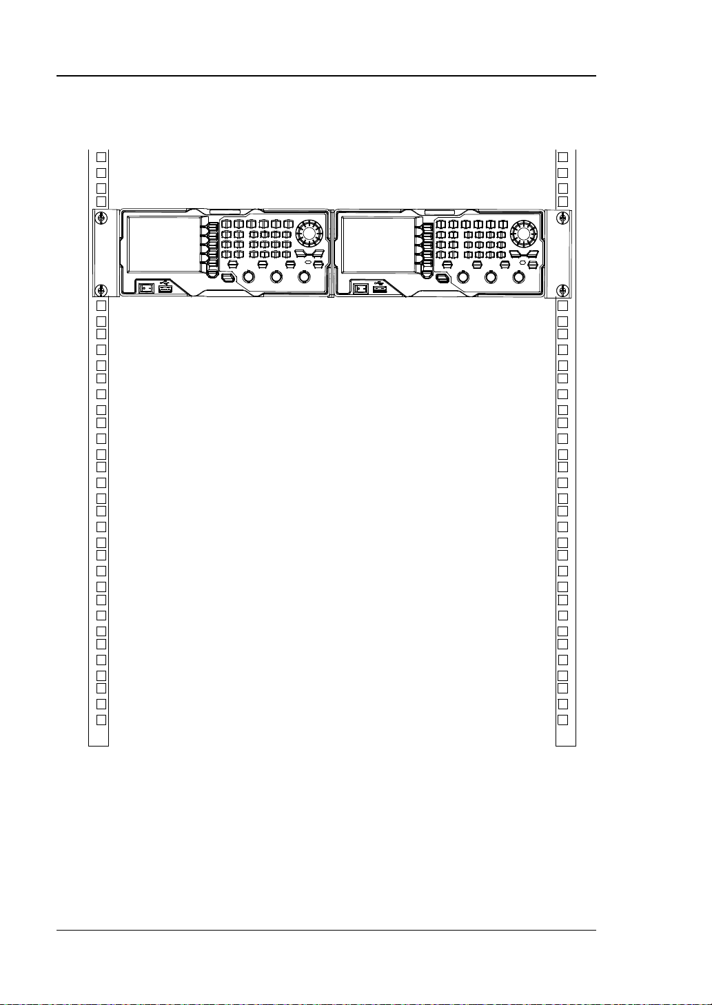
7. The f igure of the dual instruments after being installed correctly is as shown
below.
1-32 DG1000Z User’s Guide
Page 51

Chapter 2 Front Panel Operations RIGOL
Chapter 2 Front Panel Operations
This chapter introduces the main functions and operation methods of DG1000Z.
Subjects in this chapter:
To Output B asic Waveform
To Output Arbitrary Waveform
To Output Harmonic
Modulation
Sweep
Burst
Counter
Store and Recall
Utility and System Settings
DG1000Z User’s Guide 2-1
Page 52

RIGOL Chapter 2 Front Panel Operations
KEY POINT:
To Output Basic Waveform
DG1000Z series can output basic waveforms (Sine, Square, Ramp, Pulse and Noise)
from one of the channels separately or from the two channels at the same time. At
start-up, the dual channels are configured to output a sine waveform with 1kHz
frequency and 5Vpp amplitude by default. Users can conf igure the instrument to
output various basic waveforms.
To Select Output Channel
The front-panel key CH1|CH2 is used to switch the currently selected channel
between CH1 and CH2. At start-up, CH1 is selected by def ault and the corresponding
area in the user interface is highlighted and the border of the channel status bar is
displayed in yellow . At this point, pressing CH1|CH2 at the front panel to select CH2,
the corresponding area in the user interface is highlighted and the border of the
channel status bar is displayed in blue.
After the desired channel is selected, users can configure the waveform and
parameters of the channel selected.
CH1 and CH2 can n ot be s elected at the same time. Users can first select CH1 and
then select CH2 after config u r ing the waveform and parameters of CH1.
2-2 DG1000Z User’s Guide
Page 53

Chapter 2 Front Panel Operations RIGOL
Sine
Square
Ramp
Pulse
Noise
Function Name
Sine
Squ
Ramp
Pulse
Noise
Frequency/
Period
√
√ √ √
Amplitude/
High Level
√
√ √ √
√
Offset/
Low Level
√
√ √ √
√
√
√ √ √
Align Phase
√
√ √ √
Duty Cycle
√
Symmetry
√
PulseWidth
/DutyCycle
√
Leading
Edge
√
Trailing
Edge
√
To Select Basic Waveform
DG1000Z can output 5 types of basic waveforms including Sine, Square, Ramp, Pulse
and Noise. The five function keys at the front panel are used to select the
corresponding waveform. Press the corresponding key to select the desired
waveform. At this point, the backlight of the button turns on and the corresponding
function name and parameter set ting menu (as shown in the table below) are
displayed at the right of the user interface. At start-up, CH1 is selected by def ault .
Table 2-1 Bas ic Wavefo r ms
Basic Waveforms
Function Keys
Parameters
Start Phase
DG1000Z User’s Guide 2-3
Page 54

RIGOL Chapter 2 Front Panel Operations
To Set Frequency/Period
Frequency is one of the most im portant par ameters of basic w av eform s. F or di fferen t
instrument models and w av eforms, the set ting ra nges of frequenc y are differe nt. F o r
detailed information, please refer to “Frequency Characteristics” in “Specifications”.
The default frequency is 1kHz.
The frequency displayed on the screen is the default value or the frequency
previously set. When the instrument function is changed, if this frequency is valid
under the new function, the instrument will still use this frequency; otherwise, the
instrument would display prompt message and set the frequency to the frequency
upper limit of the new function automatically.
Press Freq/Period to highlight “Freq”. At this point, use the numeric keyboard to
input the desired frequency value and then select the desired unit from the pop-up
menu.
The frequency units available are MHz, kHz, Hz, mHz and μHz.
Press this softkey again to switch to period setting. At this point, “Period” is
highlighted.
The period units available are sec, msec, μsec and nsec.
Users can also use the direction keys and knob to set the parameter value: use the
direction keys to move the cursor to s elect the digit to be edite d and then rotate the
knob to change the number.
2-4 DG1000Z User’s Guide
Page 55

Chapter 2 Front Panel Operations RIGOL
KEY POINTS:
is the unit for signal
in the numeric board to
To Set Amplitude/High Level
The amplitude setting range is limited by the “Impedance” and “Freq/Period” settings.
Please refer to “Output Characteristics” in “Specifications
5Vpp.
The amplitude displayed on the screen is the default value or the amplitude
previously set. When the i nstrument configuration (such as frequenc y) is chan ged, if
this amplitude is valid, the instrument will still use this amplitude; otherwise, the
instrument would display prompt message and set the amplitude to the amplitude
upper limit of the new configuration automatically. Users can also use “High Level” or
“Low Level” to set the amplitude.
Press Ampl/HiLevel to highlight “Ampl”. At this point, use the nu meri c ke yboar d to
input the desired amplitude value and then select the desired unit from the pop-up
menu.
The amplitude units available are Vpp, mVpp, Vrms, mVrms and dBm (invalid in
HighZ).
Press this softkey again to switch to high level setting. At thi s point, “HiLevel” is
highlighted.
The high level units available are V and mV.
Users can also use the direction keys and knob to set the parameter value: use the
direction keys to move the cursor to select the digit to be edited and then r otate the
knob to change the number.
”. The default value is
1. How to convert the amplitude in Vpp to the corresponding value in
Vrms?
Method:
Vpp is the unit for signal peak-peak value and Vrms
effective value. The default unit is Vpp. Press ·
quickly switch the current amplitude unit.
Note:
For different waveforms, the relation between Vpp and Vrms is differen t . T he
relation of the two units is as shown in the figure below (take sine waveform
as an example).
DG1000Z User’s Guide 2-5
Page 56

RIGOL Chapter 2 Front Panel Operations
Vpp=2Vamp
Vrms=0.707Vamp
Vamp
Vrms22Vpp =
in the numeric
to the corresponding value in
to highlight
se the numeric keyboard to input the desired value and then
2
1
10lg( )
0.001
Vrms
dBm
RW
= ×
In this equation, R represents the channel output imp edance value a nd it must
unit dBm is not available when the output
and the amplitude is
According to t he figure ab ov e, t he c on ve rsi on rel ati o n be twe en Vpp and Vrms
fulfills the following equation:
For example, if the current amplitude is 5Vpp, press ·
keyboard and select “Vrms” to convert 5Vpp
Vrms. For sine waveform, the converted value is 1.768Vrms.
2. How to set the amplitude of waveform in the unit of dBm?
Method:
1) Press CH1|CH2 to select the desired channel.
2) Press Utility ChannelSet OutputSet Imped to select “Load”
and set proper load value using numeric keyboard.
3) Select the desired waveform and press Ampl/HiLevel
“Ampl”. U
select dBm from the pop-up menu.
Note:
dBm is the unit for signal power absolute value and the conversion relation
between dBm and Vrms fulfills the following equation:
be a certain value, so the
impedance is “HighZ”.
For example, if the current output impedance is 50Ω
1.768Vrms (5Vpp), press · in the numeric keyboa rd a nd then select “dBm”
to convert the amplitude value to the corresponding value in dBm. The
converted value is 17.9601dBm.
2-6 DG1000Z User’s Guide
Page 57

Chapter 2 Front Panel Operations RIGOL
To Set Offset/ Lo w Level
The DC offset setting range is limited by the “Impedance” and “Ampl/HiLevel”
settings. Please refer to the “Output Characteristics” in “Specifications
default value is 0V
DC
.
The DC offset voltage displayed on the screen is the default value or the offset
previously set. When the instrument configuration (such as impedance) is changed,
if this offset is v alid, the instrument will s till use this offset; otherwise, the instrument
would display prompt message and set the offset to the offset up per limit of the new
conf iguration automatically.
Press Offset/LoLevel to highlight “Offset”. At this point, use the numeric keyboar d
to input the desired offset value and then select the desired unit from the pop-up
menu.
The DC offset voltage units available are VDC and mVDC.
Press this softkey again to switch to low level setting. At this point, “LoLevel” is
highlighted.
The low level should be lower than the high level at least 1mV (the output
impedance is 50Ω).
The low level units available are V and mV.
Users can also use the direction keys and knob to set the parameter value: use the
direction keys to move the cursor to select the digit to be edited and then r otate the
knob to change the number.
”. The
DG1000Z User’s Guide 2-7
Page 58

RIGOL Chapter 2 Front Panel Operations
To Set Start Phase
The setting range of start phase is from 0° to 360° and the default is 0°.
The start phase displayed on the screen is the default value or the phase previously
set. When the instrument function is changed, the new function will still use this
phase.
Press Start Phase to highlight the softkey. At this point, use th e n um e r ic k ey bo a rd
to input the desired start phase value and then select the unit “°” from the pop-up
menu.
Users can also use the direction keys and knob to set the parameter value: use the
direction keys to move the cursor to select the digit to be edited and then rotate the
knob to change the number.
2-8 DG1000Z User’s Guide
Page 59

Chapter 2 Front Panel Operations RIGOL
KET POINTS:
one of the two
channels is in modulation mode.
CH1
CH2
CH1
CH2
Align Phase
DG1000Z series du al-channel generators enable to align the phases of the two
channels. Pressing down this softkey will re-conf igure the two channels and enable
the generator to output with specified frequency and start phase.
For two signals whose frequencies are the same or in multiple, this operation will
align their phases. For example, assume a sine waveform (1kHz, 5Vpp, 0°) is
outputed from CH1, while another one (1kHz, 5Vpp, 180°) from CH2. Use an
oscilloscope to sample and display the two signals, you will see that the waveforms
shown on the oscilloscope do not always have a phase deviation of 180°. At this
point, press Align Phase on the generator and the waveforms shown on the
oscilloscope will have a phase deviation of 180° without any adjustment of the start
phase of the generator.
Figure 2-1 Before Aligning Phase
Figure 2-2 After Aligning Phase
The Align Phase menu is grayed out and disabled when any
DG1000Z User’s Guide 2-9
Page 60

RIGOL Chapter 2 Front Panel Operations
T
t
Duty Cycle=t/T*100%
To Set Duty Cycle (Square)
Duty cycle is d efined as the percentage that the high level takes up in the whole
period (as shown in the figure below). This par ameter is only available whe n square
is selected.
The setting range of duty cycle is li mited b y the “Freq/Period” setting. Please refer
to “Signal Characteristics” in “Specifications
Press Du ty C ycl e to highlight the softkey. At this point, use the numeric ke yboard to
input the desired duty cycle value and then select the unit “%” from the pop-up
menu.
Users can also use the direction keys and knob to set the parameter value: use the
direction keys to move the cursor to select the digit to be edited and then r otate the
knob to change the number.
”. The default value is 50%.
2-10 DG1000Z User’s Guide
Page 61

Chapter 2 Front Panel Operations RIGOL
T
t
Symmetry
=t
/T
*
100%
To Set Symmetry (Ramp)
Symmetry is defined as the percentage that the rising period takes up in the whole
period (as shown in the figure below). This par amet er is only av aila ble when ramp is
selected.
The setting range of symmetry is from 0% to 100% and the default is 50%.
Press Symm to highlight the softkey. At this point, use the numeric keyboard to
input the desired symmetry value and then select the unit “%” from the pop-up
menu.
Users can also use the direction keys and knob to set the parameter value: use the
direction keys to move the cursor to select the digit to be edited and then rotate the
knob to change the number.
DG1000Z User’s Guide 2-11
Page 62

RIGOL Chapter 2 Front Panel Operations
10%
90%
50%
Pulse Width
Pulse Period
t
t
To Set Pulse Width/Duty Cycle (Pulse)
Pulse width is defined as the time from the 50% threshold of a rising edge a mplitude
to the 50% threshold of the next falling edge amplitude (as shown in the figure
below).
Rise
The setting range of pulse width is limited by the “Minimum Pulse Width” and the
“Pulse Period” (for the ranges o f “Minimum Pulse Width” and “Pulse Period”, please
refer to “Signal Characteristics” in “Specifications”). The range of pulse width is
from 16ns to 999.999 982 118ks and the def ault value is 500μs.
Pulse Width ≥ Minimum Pulse Width
Pulse Width < Pulse Period - Minimum Pulse Width×2
Pulse duty cycle is defined as the percentage that the pulse width takes up in the
whole perio d.
Pulse duty cycle and p ulse width are correlative. Once a parameter is changed, the
other will be automatically changed. Pulse duty cycle is limited by the “Minimum
Pulse Width” and the “Pulse Period”. The range of pulse duty cycle is from 0.001% to
99.999% and the default is 50%.
Pulse Duty Cycle ≥ 100×Minimum Pulse Width ÷ Pulse Period
Pulse Duty Cycle < 100×(1-2×Minimum Pulse Width÷Pulse Period)
Press Width/Duty to highlight “Width”. At this point, use the numeric keyboard to
input the desired pulse width value and then select t he desi red unit fro m the pop-up
menu.
The pulse width units available are sec, msec, μsec and ns e c.
Press this softkey again to switch to duty cycle setting.
Fall
2-12 DG1000Z User’s Guide
Page 63

Chapter 2 Front Panel Operations RIGOL
10%
90%
50%
t
t
Pulse Width
Pulse Period
Users can also use the direction keys and knob to set the parameter value: use the
direction keys to move the cursor to select the digit to be edited and then r otate the
knob to change the number.
To Set Leading/Trailing Edge Time (Pulse)
Leading (rising) edge time is defined as the duration of the pulse amplitude rising
from 10% to 90% threshold, while Trailing (falling) edge time is defined as the
duration of the pulse amplitude moving down from 90% to 10% threshold (as shown
in the figure below).
The setting range of leading/trailing edge time is limited by the currently specif ied
pulse width limit (as shown in the f ormula below). DG1000Z will aut omatically adjust
the edge time to match the specified pulse width if the value currently set exceeds
the limit value.
Leading/Trailing Edge Time ≤ 0.625 × Pulse Width
Rise
Press Leading (Trailing) to highlight “Leading” (“Trailing”). Use the numeric
keyboard to input the desired v alue and t hen select t he desire d unit from the pop-up
menu.
The Leading/Trailing Edge Time units available are sec, msec, μsec and nsec .
Leading edge time and trailing edge time are independent from each other and
users can set them separately.
Users can also use the direction keys and knob to set the parameter value: use the
direction keys to move the cursor to select the digit t o be edited and then rotate the
knob to change the number.
Fall
DG1000Z User’s Guide 2-13
Page 64

RIGOL Chapter 2 Front Panel Operations
To Enable Output
After configuring the parameters of the waveform selected, waveform output could
be enabled.
Before enabling waveform output, you can also configure parameters (such as
Impedance and Polarity) related to the channel output through Channel Set menu
in Utility. For details, please refer to the introduction in “
Press Output1 at the front panel to turn CH1 output on. At this point , t he backlight
of the button turns on and the [CH1] connector at the front panel outputs the
configured waveform.
Output Set”.
2-14 DG1000Z User’s Guide
Page 65

Chapter 2 Front Panel Operations RIGOL
Example: To Output Sine Wavefo rm
This section mainly introduces how to output a sine waveform (Frequency: 20kHz,
Amplitude: 2.5Vpp, DC Offset: 500 mV
connector.
1. To select output channel
Press CH1|CH2 to select CH1. Now the border of the channel status bar is
displayed in yellow.
2. To select the Sine
Press Sine to select the sine waveform. The backlight goes on and the
corresponding menu is displayed in the right of the screen.
3. To set the frequency
Press Freq/Period to highlight “Freq”, and then use the numeric keyboard to
input 20. Then, select “kHz” from the pop-up menu .
4. To set the amplitude
Press Ampl/HiLevel to highlight “Ampl”, and use the numeric keyboard to
input 2.5. Then, select “Vpp” from the pop-up menu.
5. To set the offset
Press Offset/LoLevel to highlight “Offset”, and the n use the nume ric k eyboard
to input 500. Then, select “mV
6. To set the start phase
Press Start Phase, and then use the numeric keyboard to input 90. Then,
select “°” from the pop-up menu. The start phase ranges from 0° to 36 0°.
7. To enable the output
Press Output1 to turn CH1 output on. At this point, the backlight goes on and
the [CH1] connector outputs the configured waveform.
8. To observe the output waveform
Connect the [CH1] con n ector of DG1000Z to the oscilloscope using BNC cable.
The waveform is as shown in the figure below.
DC, Start Phase: 90°) from the [CH1]
DC” from the p op-up menu.
DG1000Z User’s Guide 2-15
Page 66

RIGOL Chapter 2 Front Panel Operations
Figure 2-3 Sine Waveform
2-16 DG1000Z User’s Guide
Page 67

Chapter 2 Front Panel Operations RIGOL
To Output Arbitrary Waveform
DG1000Z can output built-in or user-defined arbitrary waveforms from a single
channel or from two channels at the same time. It not only provides 1 60 k inds of
built-in arbitrary waveforms stored in the internal non-volatile memory but also
allows users to edit the arbitrary waveform which can contain 8 to 16384 (16k) data
points, namely 8pts to 16kpts. Users can store the edited arbitrary waveform in the
internal or external memory (*.RAF file).
DG1000Z provides 8Mpts standard memor y and 16Mpts optional memory for the
arbitrary waveform. Users c an edit the arb itrary wavef orm using P C softwar e and
output it after downloading it to the instrument via the remote interface or reading it
from the USB storage device.
To Enable Arbitrary Waveform
Press Arb to enable arbitrary waveform function and open the operation menu of
arbitrary waveform.
1. Freq/Period: set the output Frequency/Period of the arbitrary waveform. This
menu is only displayed when the frequency output mode is selected.
2. Sample Rate: set the output Sample Rate of the arb itrary wav eform. This men u
is only displayed when the sample rate output mode is s elected.
3. Ampl/HiLevel: set the Amplitude/High Level of the arbitrary waveform.
4. Offset/LoLevel: set the Offset/Low Level of the arbitrary waveform.
5. Start Phase: set the Start Phase of the arbitrary waveform.
6. Align Phase: refer to “Align Phase”.
7. Arb Mode: switch the arbitrar y waveform output mode between “Frequency”
and “Sample Rate”.
8. Select Wform: select DC, the built-in arbitrary waveforms, the arbitrary
waveforms stored in internal or external memory or the volatile waveform.
9. Edit Wform: edit the selected waveform of the current channel or create a new
waveform.
Pleas e refer to “To Output Basic Waveform” to conf igure the parame ters and
output of the channels. This chapter will focus on “Sample Rate”, “Output Mode”,
“Select Waveform” and “Edit Waveform”.
DG1000Z User’s Guide 2-17
Page 68

RIGOL Chapter 2 Front Panel Operations
Output Mode a n d Sample Rate
DG1000Z supports Frequency and Sample Rate output modes.
1. Frequency Output Mode
Press Arb Arb Mode to select the “Frequency” output mode.
In frequency output mode, users can s et the fre quency or perio d of the a rbitrary
waveform (the setting method please refer to “To Set Frequency/Period”)
while the sample rate can not be changed. The instrument outputs an arbitrary
waveform which is made up of certain points selected according to the current
output frequency.
For arbitrary waveform, frequency output mode corresponds to period edit
mode (Arb Edit Wform Mode “Period”). If the currently selected
arbitrary waveform is in the period edit mode when the state of RealTime
under Edit Wform is “On”, the instrument will switch to frequenc y output mo de
automatically.
2. Sample Rate Output Mode
Press Arb Arb Mode to select the “Sample Rate” mode.
In sample rate output mode, users can set the sample rate (the points outputted
per second) while the frequency an d period can not be changed. The instrument
outputs the arbitrary waveform point by point according to the current sample
rate.
After the sample rate output mode is selected, press SRate to input the desire d
sample rate value using the numeric keyboard and select the desired unit from
the pop-up menu.
The range available of the sample r at e is from 1μSa/s to 60MSa/s.
The sample rate units availabl e are MSa/s, kSa/s, Sa/s, mSa/s and μSa/s.
Users can also use the direction keys and knob to set the parameter value: use
the direction keys to move the cursor to select the digit to be edited and then
rotate the knob to change the number.
For arbitrary waveform, the sample rate output mode corresponds to the sample
rate edi t mode ( Arb Edit Wform Mode “Period”). If the currently
selected arbitrary waveform is in the sample rate edit mode when the state of
RealTime under Edit Wform is “On”, the instrument will switch to sample rat e
output mode automatically.
2-18 DG1000Z User’s Guide
Page 69

Chapter 2 Front Panel Operations RIGOL
KEY POINTS:
To Select Arbitrary Waveform
DG1000Z allows users to select DC, 160 built-in waveforms, arbitrary waveforms
stored in internal or external memory of the instrument or volatile memory.
After the desired waveform is selected, you can perform the operations below.
1. To output the selected waveform:
Press the corresponding output control key Output1 or Output2 and t he
specif ied waveform will be outputted from the channel.
2. To edit the selected waveform:
Please refer to the introduction in “To Edit Arbitrary Waveform
DC
DG1000Z can output DC signal with amplitude range from -10V to 10V (HighZ) or
from -5V to 5V (the load is 5 0 Ω). The figure below shows a sketch of the DC signal.
Press Arb Select Wform DC to select DC signal.
”.
DG1000Z User’s Guide 2-19
Figure 2-4 Sketch of DC signal
Page 70

RIGOL Chapter 2 Front Panel Operations
Sub-item
Waveform
Explanation
Engineering
Sinc
Sinc function
Lorentz
Lorentz function
Log
Logarithm function and the base is 10
GaussPulse
Gauss pulse
NegRamp
Negative ramp
NPulse
Negative pulse
PPulse
Positive pulse
SineTra
Sine-Tra waveform
SineVer
Sine-Ver waveform
StairDn
Stair-down waveform
StairUD
Stair-up and stair-down waveform
Sub-item Bar
Built-In
Item
Number of Current Page/
Number of Current Waveform/
Total Number of Waveforms
Built-In Waveform
DG1000Z has 160 built-in arbitrary waveforms as shown in Table 2-2
Select Wform BuiltIn to enter the built-in waveform selection interface as
shown in the figure below. Press Engine, Medical, AutoElec or Maths to se lect
the corresponding item (each item has one or more sub-items). Press the
correspond ing m en u key repeatedly to switch to the desired sub-item (the selected
sub-item in the sub-item bar is highli ghted) and rotate t he knob to select the de sired
waveform (the selected waveform is highlighted). Then press Select to select the
waveform which is highlighted.
Total Number of Pages
Waveform
. Press Arb
Figure 2-5 Built-in Waveform
Table 2-2 160 Built-in Arbitrary Waveforms
Normal
Menu
2-20 DG1000Z User’s Guide
Page 71

Chapter 2 Front Panel Operations RIGOL
StairUp
Stair-up waveform
Trapezia
Trapezia waveform
AmpALT
Gain oscillation curve
AttALT
Attenuation oscillation curve
RoundHalf
RoundHalf Wave
RounsPM
RoundsPM Waveform
BlaseiWave
Time-velocity curve of explosive vibration
DampedOsc
Time-displacement curve of damped oscillation
SwingOsc
Kinetic energy- time curv e of swin g oscillation
Discharge
Discharge curve of Ni-MH battery
Pahcur
Current waveform of DC brushles s motor
Combin
Combination function
SCR
SCR firing profile
Butterworth
Butterworth filter
Chebyshev1
Chebyshev1 filter
Chebyshev2
Chebyshev2 filter
TV
TV sign al
Voice
Voice signal
Surge
Surge signal
Radar
Analog radar waveform
DualTone
Dual-tone signal
Ripple
Ripple wave of battery
Quake
Analog quake waveform
Gamma
Gamma signal
StepResp
Step-response signal
BandLimited
Bandwidth-limited signal
CPulse
C-Pulse
CWPulse
CW pulse
GateVibr
Gate self-oscillation signal
LFMPulse
Linear FM pulse
MCNoise
Mechanical construction noise
AM
Sectioned sine AM signal
FM
Sectioned sine FM signal
PFM
Sectioned pulse FM signal
PM
Sectioned sine PM signal
PWM
Sectioned PWM signal
Medical
Cardiac
Cardiac signal
EOG
Electro-Oculogram
EEG
Electroencephalogram
EMG
Electromyogram
Pulseilogram
Pulsilogram
ResSpeed
Speed curve of the respirati on
Engine
Filter
Signal
Mod
BIO
DG1000Z User’s Guide 2-21
Page 72

RIGOL Chapter 2 Front Panel Operations
ECG1
Electrocardiogram 1
ECG2
Electrocardiogram 2
ECG3
Electrocardiogram 3
ECG4
Electrocardiogram 4
ECG5
Electrocardiogram 5
ECG6
Electrocardiogram 6
ECG7
Electrocardiogram 7
ECG8
Electrocardiogram 8
ECG9
Electrocardiogram 9
ECG10
Electrocardiogram 10
ECG11
Electrocardiogram 11
ECG12
Electrocardiogram 12
ECG13
Electrocardiogram 13
ECG14
Electrocardiogram 14
ECG15
Electrocardiogram 15
Waveform of the low frequency pulse
electrotherapy
Waveform 1 of the nerve stimulation
electrotherapy
Waveform 2 of the nerve stimulation
electrotherapy
Waveform 3 of the nerve stimulation
electrotherapy
AutoElec
Ignition
Ignition waveform of the automotive motor
ISO16750-2 SP
Automotive starting profile with ringing
ISO16750-2 VR
Automotive supply voltage profile for resetting
ISO7637-2 TP1
Automotive transients due to disconnects
Automotive transients due to inductance in
wiring
ISO7637-2 TP2B
Automotive transients due ignition switching off
ISO7637-2 TP3A
Automotive transients due to switching
ISO7637-2 TP3B
Automotive transients due to switching
ISO7637-2 TP4
Automotive supply profile during starting
ISO7637-2 TP5A
Automotive transients due to battery disconnect
ISO7637-2 TP5B
Automotive transients due to battery disconnect
Maths
Airy
Airy function
Besselj
BesselI function
Bessely
BesselII function
Cubic
Cubic function
Dirichlet
Dirichlet function
LFPulse
Tens1
Medical
Tens2
Auto
MF
Tens3
ISO7637-2 TP2A
2-22 DG1000Z User’s Guide
Page 73

Chapter 2 Front Panel Operations RIGOL
Erf
Error function
Erfc
Complementary error function
ErfcInv
Inverted complementary error function
ErfInv
Inverted error function
ExpFall
Exponential fall function
ExpRise
Exponential rise function
HaverSine
HaverSine function
Laguerre
4-times Laguerre polynomial
Legend
5-times Legend polynomial
Versiera
Versiera
ARB_X2
Square function
Gauss
Gauss distribution
Weibull
Weibull distribution
LogNormal
Logarithmic Gaussian distribution
Laplace
Laplace distribution
Maxwell
Maxwell distribution
Rayleigh
Rayleigh distribution
Cauchy
Cauchy distribution function
CosH
Hyperbolic cosine
CosInt
Integral cosine
Cot
Cotangent
CotHCon
Concave hyperbolic cotangent
CotHPro
Protuberant hyperbolic cot angent
CscCon
Concave cosecant
CscPro
Protuberant cosecant
CscHCon
Concave hyperbolic cosecan t
CscHPro
Protuberant hyperbolic cose cant
RecipCon
Concave re ci procal
RecipPro
Protubera nt reciprocal
SecCon
Concave secant
SecPro
Protuberant secant
SecH
Hyperbolic secant
SinH
Hyperbolic sine
SinInt
Integral sine
Sqrt
Square root
Tan
Tangent
TanH
Hyperbolic tangent
AbsSine
Absolute value of sine
AbsSineHalf
Absolute value of half a sine
ACos
Arc cosine
ACosH
Arc hyperbolic cosine
ACotCon
Concave a rc cotangent
ACotPro
Protuberant arc cotangen
ACotHCon
Concave arc hyperbolic cotangent
DF
TF
ITF
DG1000Z User’s Guide 2-23
Page 74

RIGOL Chapter 2 Front Panel Operations
ACotHPro
Protuberant arc hyperbolic cotangent
ACscCon
Concave a rc cosecant
ACscPro
Protuberant arc cosecant
ACscHCon
Concave arc hyperbolic cosecant
ACscHPro
Protuberant arc hyperbolic cosecant
ASecCon
Concave arc secant
ASecPro
Protuberant arc seca n t
ASecH
Arc hyperbolic sec a n t
ASin
Arc Sinc
ASinH
Arc hyperbolic sine
ATan
Arc tangent
ATanH
Arc hyperbolic tangent
Bartlett
Bartlett window
BarthannWin
Modified Bartlett-Hann window
Blackman
Blackman window
BlackmanH
BlackmanH window
BohmanWin
Bohman wi ndow
Boxcar
Rectangle window
ChebWin
Chebyshev window
FlattopWin
Flat Top weighted window
Hamming
Hamming window
Hanning
Hanning window
Kaiser
Kaiser window
Nuttall-defined minimum 4-term
Blackman-Harris window
ParzenWin
Parzen window
TaylorWin
Taylor window
Triang
Triangle window (Fejer window)
TukeyWin
Tukey (tapered cosine) window
WF
NuttallWin
Stored Waveform
Select arbitrary waveforms stored in internal non-volatile memory (C Disk) or
external memory (D Disk). Press Arb Select Wform Stored Wforms to
enter the Store/Recall Interface and the Store key at the front panel is illuminated.
At this time, please select and read the desired arbitrary waveform file. For more
details, please refer to “
be changed after the f ile is read. Now press Arb to return to arbitrary waveform
setting interface.
Store and Recall”. Waveform data in volatile memory will
2-24 DG1000Z User’s Guide
Page 75

Chapter 2 Front Panel Operations RIGOL
Volatile Waveform
Press Arb Select Wform Volatile Wform to select arbitrary waveform
currently stored in the volatile memory. If there is no waveform data in volatile
memory currently, this menu would be unavailable. At this time, you can fill up the
volatile memory through the methods below.
1. Fill up the volatile memory with the waveform currently edited through Edit
Wform.
2. Press Arb Edit Wform D ata Src to select “CH1 Arb”、”CH2 Arb” or “Vol”.
Then copy the currently selected arbitrary waveform of CH1 or CH2 or the
waveform of the other channel’s volatile memory to the volatile memory of the
currently selected channel.
When “Volatile Wform” is selected, users can edit the volatile waveform using the
Edit Wform menu. The new waveform data will overwrite the previous dat a in the
volatile memory. You can also save the new volatile waveform in non-volatile
memory.
DG1000Z User’s Guide 2-25
Page 76

RIGOL Chapter 2 Front Panel Operations
To Edit Arbitrary Waveform
DG1000Z allows users to edit the waveform in the volatile memory of the channel
currently selected. If there is no w a vef orm data i n th e v olatile me mory c urrentl y, the
system will automatically creat 8 (under sample rate edit mode) or 8192 (under
period edit mode) data points whose voltage are low level. You can also copy the
arbitrary waveform currently selected of CH1 or CH2 or the waveform o f the other
channel’s volatile memory to the volatile memory of the channel currently selected
for editing.
Press Arb Edit Wform to enter the waveform editing interface.
1. Edit Mode
Press Mode and select “Sample Rate” or “Period” mode.
1) In Sa m ple Rate Edit Mode:
The range of the sample rate is from 1μSa/s to 60MSa/s and the
default is 20MSa/s. Fo r the setting method, refer to “Output Mode
and Sample Rate”.
The range of the points (denoted by Sa) is from 8 to 16384 (namely
16k) and the default is 8. Users can respectively select the number of
the Sa points and set voltage for each point.
2) In Period Edit Mode:
The range of the period is from 50ns to 1Ms and the default is 1ms. For
the setting method, refer to “To Set Frequency/Period”.
The range of the p oints (denoted by Sa) is from 8 to 8192 (namely 8k)
and the default is 8192. The period currently set is devided equally to
8191 (8192-1), namely 8192 points. Each point corresponds a data
point (0s corresponds to the first data point and the current period
corresponds to the 8192th point. Users can respectively select the
number of the Sa points and set voltage for each point. The voltage
values of all other points remain low level.
2. High Level
It refers to the highest voltage that can be set when editing waveform. Press
HiLevel, input the desired value using the numeric keyboard, a nd select th e
desired unit (the unit s a v ai lable are V and mV) from the pop-up menu. The high
level must be higher than the “Low Level” currently set and lower than or equal
to +10V (HighZ).
2-26 DG1000Z User’s Guide
Page 77

Chapter 2 Front Panel Operations RIGOL
3. Low Level
It refers to the lowest voltage that can be set when editing waveform. Press
LoLevel, input the desired value using the numeric keyboard, and select the
desired unit (the units available are V and mV) from the pop-up menu. The low
level must be higher than or equal to -10V (HighZ) and lower than the “High
Level” currently set.
4. Points (denoted by Sa)
In sample rate edit mode, the range of the points is from 8 to 16384 (16K). In
period edit mode, the range of the points is from 8 to 8192 (8K). Press Points,
input the desired value using the numeric keyboard, and select OK from the
pop-up men u. At this time, the prompt message (modify arbitrary waveform
points, original data will be lost) is displayed and you need to select OK again.
Note: when the points is modified, the original waveform data in volatile
memory will be lost.
5. Data Source
Press Data Src to select “CH1 Arb”, “CH2 Arb” or “Volatile”. You can copy the
arbitrary waveform currently selected by CH1 or CH2 or the volatile waveform of
the other channel to the volatile memory of the currently selected channel and
edit them.
6. Insert Waveform
Insert the specified waveform at the specif ied position of the waveform edited
currently. Press this menu key to enter “I n s e rt Waveform” interface.
Insert Position
Set the start position for inserting the waveform. Press this menu key and
input the desired value using the numeric keyboard or direction keys and
knob. The range is from 1 to Sa and Sa indicates current total points. For
example, if the insert position set is 7, the instrument will insert a w avef orm
from the seventh point.
Insert Way
Select the insert way between “Insert” and “Rewrite”.
In insert way, when inserting the selected waveform at the specified insert
position, the original waveform data will be moved behind the inserted
waveform.
In rewrite way, the inserted waveform will overwrite t he origi nal waveform
from the specified insert position.
DG1000Z User’s Guide 2-27
Page 78

RIGOL Chapter 2 Front Panel Operations
Cycles
Set the cycles of the inserted waveform. The range is from 1 to 16 and the
default is 1. The each cycle’s points of the inserted waveform is fixed at
1024.
Select Waveform
Select the waveform to be inserted. You can select the basic waveforms
(Sine, Square, Ramp, Pulse and Noise) or the built -in waveforms (160 types
optional, refer to Table 2-2).
Note: when inserting a wa veform, you sh ould first set the insert position, inse rt
way and cycles, and then select the desired waveform types (because the insert
operation will be executed immediately after the desired waveform is selected).
7. Edit Points
Sa is used to denote the points currently set. In point edit mode, users can
select the number of the first Sa waveform point and set the voltage for each
point. Press this menu key to enter the “Edit Points” interface.
Edit Points
Select the number (the r a nge is f rom 1 t o Sa) of the point to be edited and
input the desired v alue usi ng nume ric ke yboa rd o r direction keys and knob.
Voltage
Set the voltage of the current point (the units a v aila ble a re mV and V). The
range is limited by the current “High Level” and “Low Level”.
Insert
Insert a point at the point currently edited. The v oltage of the inserted point
is the same as the voltage value currently set and the original waveform
data are moved behind the inserted point. At this time, the number of the
points increases by 1.
Delete
Delete the current point. At this time, the number of the points decreases
by 1.
Move Position
Modify the voltage of the specif ied point to the voltage of the point
currently edited and set the voltage of the current point to low level.
Press Move Pos and input the number (the range is from 1 to Sa) of the
point to move to before pressing OK. You can also rotate t he knob to select
the number of the point to move to after pressing Move Pos.
2-28 DG1000Z User’s Guide
Page 79

Chapter 2 Front Panel Operations RIGOL
Preview
Preview the waveform currently edited.
8. Edit Block
In block edit mode, users only need to edit the numbers of the start and end
point as well as the corresponding voltages. The generator will automatically
calculate the voltage of e ach point between the st art point and end point. P ress
this menu key to enter the “Edit Block” interface.
X1
Set the number of the start point of the block. X1 should be less than or
equal to X2 and less than the points currently set.
Y1
Set the voltage (the units available are mV and V) of the start point of the
block. The range is limited by the current “High Level” and “Low Level”.
X2
Set the number of the end point of the block. X2 should be less than or
equal to the points currently set and greater than or equal to X1.
Y2
Set the voltage (the units available are mV and V) of the end point of the
block. The range is limited by the current “High Level” and “Low Level”.
Excute
Automatically edit the points between the start point and end point
according to the current settings.
Delete
Delete X1 and the points between X1 and X2.
Note: this operation is available only when the difference of the points
currently set and the points to be deleted is greater than or equal to 8.
9. Save
When the editing is finished, press Save to enter the store and recall inter face
and the backlight of Store turns on. At this time, you can store the a rbitrary
waveform edite d in internal non-volatile memory (C Disk) or external memory (D
Disk). For the store method, refer to “
Store and Recall”.
DG1000Z User’s Guide 2-29
Page 80

RIGOL Chapter 2 Front Panel Operations
......
)2
sin()
2sin(
)
2sin()
(
3
332
2
2
111
+
++
++
+=
ϕπ
ϕ
πϕπ
tf
At
f
Atf
At
f
1
f
1
f
1
A
1
ϕ
To Output Harmonic
DG1000Z can be used as a harmonic generator to output harmonic with specif ied
order, amplitude and phase. It is usuall y used in the test of harmonic detector device
or harmonic filter device. This section introduces how to configure the generator to
output harmonic.
Overview
According to Fourier transform, time domain waveform is the superposition of a
series of sine waveforms as shown in the equation below:
Generally, component with
fundamental waveform frequency,
fundamental waveform phase. The frequencies of the other components (called
harmonics) are all integral multiples of the fundamental waveform frequency.
Components whose frequencies are odd multiples of the fundamental waveform
frequency are called odd harmonics and components whose frequencies are even
multiples of the fundamental waveform frequency are called even harmonics.
DG1000Z can output up to 8th harmonic. After selecting CH1 or CH2, press Sine
Harm to select “On” and press Harmonic Para to enter the harmonic setting men u.
You can set the type of harmonic, specify the highest order of harmonic and set the
amplitude and phase of each order of harmonic. If you want to set various
parameters of fundamental waveform, please set the parameters of Sine.
After finishing harmonic parameters set t ing, press Output1 and the backlight turns
on, the instrument outputs the specified harmonic from the corresponding output
terminal.
frequency is called fundamental waveform,
is fundamental waveform amplitude,
is
is
2-30 DG1000Z User’s Guide
Page 81

Chapter 2 Front Panel Operations RIGOL
To Set Fundamental Waveform Parameters
DG1000Z allows users to set various fundamental waveform parameters such as
frequency, period, amplitu de, DC off set voltage , high level, low level a nd start p hase.
It also supports align phase operation. Please refer to introductions in “To Output
Basic Waveform” to set above fundamental waveform parameters.
To Set Harmoni c Order
The highest order of harmonic output from DG1000Z can not be greater than this
setting value.
After entering the harmoni c setting menu, press Order (at this p oint, “Order” on the
screen is highlighted) and use the numeric keyboard or knob to input the desired
harmonic order.
The range is limited by the maximum output frequency of the instrument and
current fundamental waveform frequency.
Range: 2 to maximum output frequency of the instrument÷current
fundamental waveform frequency (must be integer).
The maximum is 8.
To Select Harmonic Type
DG1000Z can output even harmonic, odd harmonic, all orders of harmonic and
user-defined orders of harmonic. After entering the harmonic setting menu, press
Type to select the desired harmonic type.
1. Even
Press this key and the instrument will output fundamental waveform and even
harmonics.
2. Odd
Press this key and the inst rument w ould output f und amental w a vef orm and odd
harmonics.
3. All
Press this key and the instrument would output fundamental waveform and all
the harmonics in order.
4. User
Press this key and the instrument would output the user-defined orders of
harmonics. The highest order is 8.
DG1000Z User’s Guide 2-31
Page 82

RIGOL Chapter 2 Front Panel Operations
8 bits binary data is used to represent the output status of the 8 orders of
harmonics respectively, wherein, 1 represents enabling the output of the
corresponding harmonic and 0 represents disabling the output of the
corresponding harmonic. Users only need to use the numeric keyboard to
modify the value of each data bit (note: the leftmost bit representing
fundamental waveform is always X and can not be modif ied). For example, set
the 8 bits data to X001 0001, thus fundamental waveform and 4th and 8th
orders of harmon ics are output.
Note: the actual harmonics output is determined by the harmonic order and
harmonic type currently specified.
To Set Harmoni c Amplitude
After entering the harmonic setting menu, press Harmonic Ampl to set the
amplitude of each order of harmonic.
1) SN: press this softke y to s elect the sequen ce nu mber of the harmonic to be set.
2) Harmonic Ampl: press this softkey to set the amplitude of the harmonic
selected. Use the numeric keyboa rd to input the amplitude v alue and then sele ct
the desired unit from the pop-up menu. The units available are Vpp, mVpp,
Vrms, mVrms and dBm (invalid in HighZ).
To Set Harmonic Phase
After entering the harmonic setting menu, press Harmonic Phase to set the phase
of each order of harmonic.。
1. SN: press this softkey to select the sequence nu mber of the harm onic to be set .
2. Harmonic Phase: press this softkey to set the phase of the harmonic selected.
Use the numeric keyboard or the direction keys and knob to input the phase
value and then select the unit “°” from the pop-up menu.
2-32 DG1000Z User’s Guide
Page 83

Chapter 2 Front Panel Operations RIGOL
Example: To O utput Harmonic
This section introduces how to output 2th order of harmonic (harmonic amplitude:
2Vpp, harmonic phase: 30°) and 4th o rders o f harmo nic (harmonic amplitude: 1Vpp,
harmonic phase: 50°) from the [CH1] connector. The fundamental waveform is the
default sine of the instrument and the harmonic order is 5.
1. To Select Output Channel: Press CH1|CH2 to select CH1. At this time, the
border of the channel status bar is displayed in yellow.
2. To Set Fundamental Waveform Parameters: In this example, various
parameters of the fundamental waveform take the default values. Yo u can also
refer to the introduction in “To Output Basic Waveform” to set various
fundamental waveform parameters such as frequency/period, amplitude/high
level, offset/low level and start phase.
3. To Enable Harmonic Function: Press Sine Harm to select “On” and press
Harmonic Para to enter the harmonic setting menu.
4. To Set Harmonic Order: In the harmonic set ting menu, press Order and use
the numeric keyboard to input 5 before pressing OK.
5. To Select Harmonic Type: In the harmonic setting menu, press Type to
select even harmonic.
6. To Select Harmonic Amplitude: In the harmonic setting menu, press
Harmonic Ampl to successively set the amplitude of 2th and 4th orders of
harmonic.
1) Press SN, input 2 (the harmonic sequence number) using the numeric
keyboard, and press OK.
2) Press Harmonic Ampl, input 2 (the value of the amplitude) using the
numeric keyboard, and select the unit “Vpp” from the pop-up units menu.
3) Refer to step 1 and 2 to set the amplitude of the 4th order harmonic to
1Vpp.
7. To Set Harmonic Phase: In the harmonic setting menu, press Harmonic
Phase to set the phase of 2th and 4th orders of harmonic successively.
1) Press SN, input 2 (the harmonic sequence number) using the numeric
keyboard, and press OK.
2) Press Harmonic Phase, input 30 (the value of the phase) using the
numeric keyboard, and select the unit “°” from the pop-up units menu.
3) Refer to step 1 and 2 to set the phase of the 4th order harmonic to 50°.
DG1000Z User’s Guide 2-33
Page 84

RIGOL Chapter 2 Front Panel Operations
8. To Enable the Output: Press Output1 and the backlight turns on. The
fundamental waveform, 2th and 4th order of harmonics will be outputted from
the [CH1] connector according to the current configuration.
9. To Observe the Output Waveform: Connet the CH1 of the DG1000Z to an
oscilloscope using BNC connect cable. The observed waveform from the
oscilloscope is shown in the f ig ure below.
Figure 2-6 Harmonic
2-34 DG1000Z User’s Guide
Page 85

Chapter 2 Front Panel Operations RIGOL
Modulation
DG1000Z can output modulated waveform from a single channel or from two
channels at the same time. Modulation is the process of modifying certain
parameters (such as amplitude, frequency, phase and etc.) of the carrier waveform
signal a ccording to the change of the modulating signal. The carrier wav eform can b e
Sine, Square, Ramp, Arbitrary waveform (except DC) or Pulse (only in PWM). The
modulating waveform can be from internal or external modulation source. DG1000Z
supports AM, FM, PM, ASK, FSK, PSK and PWM.
Amplitude Modulation (AM)
For amplitude modulation (AM), the amplitude of the carrier waveform varies with
the instantaneous voltage of the modulating waveform.
To Select AM Modulation
Press Mod Type AM to enable AM function. When Mod is enabled, Sweep or
Burst will be disabled automatically (if enabled currently).
To Select Carrier Waveform Shape
AM carrier waveform could be Sine, Square, Ramp or Arbitrary waveform (except
DC). The default is Sine.
Press the front panel key Sine, Square, Ramp or Arb (you need to press
Select Wform in the arbitrary waveform setting interface to select the desired
arbitrary waveform) to select the desired carrier waveform shape.
Pulse, Noise and DC could not be used as carrier waveform.
To Set Carrier Waveform Parameters
The different settings of various parameters (frequency, amplitude, DC offset, start
phase and etc.) of the carrier waveform will influence the AM modulated waveform.
For different carrier waveform shape, the ranges of the various parameters are
different (the ranges are related to the model of the instrument used and the carrier
waveform currently selected. See “Specifications” for details). For all carrier
waveform shapes, the default values are 1kHz frequency, 5Vpp amplitude, 0V
offset and 0° start phase.
When the carrier waveform currently selected is Sine, Square or Ramp, please
refer to the introduction in “To Output Basic Waveform” to set the
parameters of the carrier waveform currently selected.
DC
DG1000Z User’s Guide 2-35
Page 86

RIGOL Chapter 2 Front Panel Operations
[CH1/Sync/Ext Mod/Trig/FSK]
[CH2/Sync/Ext Mod/Trig/FSK]
When the carrier waveform currently selected is arbitrary waveform, please
refer to the introduction in “To Output Arbitrary Waveform” to set the
parameters of the carrier waveform currently selected.
To Select Modulation Source
DG1000Z can accept modulating waveform from internal or external modulation
source. Press Mod Source to select “Int” or “Ext” modulation source.
1. Internal So u r c e
When internal modulation sou rce is selected, p ress Shape to select Sine, Square,
Triangle, UpRamp, DnRamp, No ise or Arb as modulating waveform. The default
is Sine.
Square: 50% duty cycle
Triangle: 50% symmetry
UpRamp: 100% symmetry
DnRamp: 0% symmetry
Arb: the arbitrary waveform selected of the current channel
Note: noise can be used a s modulating wa veform but can not be use d as ca rrier
waveform.
2. External Source
When external modulation source is selected, Shape and AM Freq will be
grayed out and disable d. The generator accepts the external modulating signal
from the [CH1/Sync/Ext Mod/Trig/FSK] connector at the rear panel. At this
time, amplitude of the modulated wa vefo rm is controlled by the ±5 V signal lev el
of the connector. For example, if the modulation depth is set to 100%, the output
amplitude will be the maximum when the modulating signal is +5V and the
minimum when the modulating signal is -5V.
2-36 DG1000Z User’s Guide
Page 87

KEY POINTS:
Chapter 2 Front Panel Operations RIGOL
How to realize the intermodulation between dual channels?
The following example takes the output signal of CH2 as the modulating
waveform.
1. Connect the CH2 output terminal to [CH1/Sync /Ext Mod/Trig /FSK]
connector at the rear panel using the dual BNC connect cable.
2. Select CH1 and press Mod to select the desired modulation type as well as set
the corresponding parameters before selecting external modulation source.
3. Select CH2 and select the desired modulating waveform and set the
corresponding parameters.
4. Press Output1 to enable the output of CH1.
To Set Modulating Waveform Frequency
When internal modulation source is selected, press AM Freq to set th e modulating
waveform frequency.
Input the desired frequency value us ing the numeric keyboard or dire ct i on keys
and knob。
The modulating waveform frequency ranges from 2mHz to 1MHz, and the
default value is 100Hz.
Note: when external modulation sou rce is selected, this menu will be grayed out and
disabled.
To Set Modulation Depth
Modulation depth expressed as a percentage indicates the amplitude variation
degree. The AM modulation depth ranges from 0% to 1 20%. Press AM Depth to set
AM modulation depth.
In 0% modulation, the output amplitude is half of the carrier waveform
amplitude.
In 100% modulation, the output amplitude is equal to carrier waveform
amplitude.
In >100% modulation, the output amplitude of the instrument would not
exceed 10Vpp (50Ω load).
When external modulation sou rce is selected, the output amplitude of the inst rument
is controlled by the ±5V signal level of the [CH1/Sync/Ext Mod/Trig/FSK]
connector at the rear panel. For example, if the modulation depth is set to 100%, the
output amplitude will be the maximum when the modulating signal is +5V and the
minimum when the modulating signal is -5V.
DG1000Z User’s Guide 2-37
Page 88

RIGOL Chapter 2 Front Panel Operations
Carrier Waveform Suppression
DG1000Z supports the normal amplitude modulation and double sideband
suppressed carrier (DSB-SC) amplitude modulation. In the normal amplitude
modulation, the modulated waveform contains carrier waveform components.
Because carrier waveform components carry no information, the modulation is less
efficient. In order to improve the modulation efficiency, the carrier waveform
components a re suppress ed on the base of t he n ormal amplitude modulation . At t his
time, all modulated waveform carry information. This method is called double
sideband suppressed carrier modulation. By default, DG1000Z works in the normal
amplitude modulation and users can enable the double sideband suppressed carrier
modulation through pressing the menu key DSSC and selecting “On”.
2-38 DG1000Z User’s Guide
Page 89

Chapter 2 Front Panel Operations RIGOL
Frequency Mo du lation (FM)
For frequency modulation (FM), the frequency of the carrier waveform varies with
the instantaneous voltage of the modulating waveform.
To Select FM Modulation
Press Mod Type FM to ena ble FM function. W hen Mod is enabled, Sweep or
Burst will be disabled automatically (if enabled currently).
To Select Carrier Waveform Shape
FM carrier waveform could be Sine, Square, Ramp or Arbitrary waveform (except
DC). The default is Sine.
Press the front panel key Sine, Square, Ramp or Arb (you need to press
Select Wform in the arbitrary waveform setting interface to select the desired
arbitrary waveform) to select the desired carrier waveform shape.
Pulse, Noise and DC could not be used as carrier waveform.
To Set Carrier Waveform Parameters
The different settings of various parameters (frequency, amplitude, DC offset, start
phase and etc.) of the carrier waveform will influence the FM modulated waveform.
For different carrier waveform shape, the ranges of the various parameters are
different (the ran ges are relat ed to the model of the instrument used an d the carrie r
waveform currently selected. See “Specifications” for details). For all carrier
waveform shapes, the default values are 1kHz frequency, 5Vpp amplitude, 0V
offset and 0 ° start phase.
When the carrier waveform currently selected is Sine, Square or Ramp, please
refer to the introduction in “To Output Basic Waveform” to set the
parameters of the carrier waveform currently selected.
When the carrier waveform currently selected is arbitrary waveform, please
refer to the introduction in “To Output Arbitrary Waveform” to set the
parameters of the carrier waveform currently selected.
DC
DG1000Z User’s Guide 2-39
Page 90

RIGOL Chapter 2 Front Panel Operations
[CH1/Sync/Ext Mod/Trig/FSK]
[CH2/Sync/Ext Mod/Trig/FSK]
To Select Modulation Source
DG1000Z can accept modulating waveform from internal or external modulation
source. Press Mod Source to select “Int” or “Ext” modulation source.
1. Internal So u r c e
When internal modulation sou rce is selected, p ress Shape to select Sine, Square,
Triangle, UpRamp, DnRamp, Noise or Arb as modulating waveform. The default
is Sine.
Square: 50% duty cycle
Triangle: 50% symmetry
UpRamp: 100% symmetry
DnRamp: 0% symmetry
Arb: the arbitrary waveform selected of the current channel
Note: noise can be used a s modulating wa veform but can not be use d as ca rrier
waveform.
2. External Source
When external modulation source is selected, Shape and FM Freq will be
grayed ou t and disabled. The generator accepts the external modulating signal
from the [CH1/Sync/Ext Mod/Trig/FSK] connector at the rear panel. At t his
time, frequency deviation of the modulated waveform is controlled by the ±5 V
signal level of the connector. For example, if the frequency deviation is set to 1
kHz, +5V signal level corresponds to a 1kHz increase of frequency and -5V signal
level corresponds to a 1kHz decrease of frequency.
2-40 DG1000Z User’s Guide
Page 91

Chapter 2 Front Panel Operations RIGOL
To Set Modulating Waveform Frequency
When internal modulation source is selected, press FM Freq to set the modulating
waveform frequency.
Input the desired frequency value us ing the numeric keyboard or dire ct i on keys
and k n ob.
The modulating waveform frequency ranges from 2mHz to 1MHz, and the
default value is 100Hz.
Note: when external modulation sou rce is selected, this menu will be grayed out and
disabled.
To Set Frequency Deviation
Frequency deviation is the deviation of the modulating waveform frequency relative
to the carrier frequency. Press FM Dev to set the FM freque nc y deviati on.
Frequency deviation must be lower than or equal to the carrier frequency.
The sum of frequency deviation and carrier frequency must be lower than or
equal to the sum of the current carrier frequency upper limit and 1kHz.
Note: if Sine is selected c urrently as the carrier w a vef orm, the carrie r amplitu de wil l
be limited at 2Vpp when the sum of the frequency deviation and the carrier
frequency is greater than the frequency upper limit of the current carrier.
When external modulation source is selected, the frequency deviation is controlled
by the ±5V signal level of the [CH1/Sync/Ext Mod/Trig/FSK] connector at the
rear panel. Positive signal level corresponds to frequency increase and negative
signal level corresponds to frequency decrease. For example, if the frequency
deviation is set to 1 kHz, +5V signal level corresponds to a 1kHz increase of
frequency and -5V signal level corresponds to a 1kHz decrease of frequency.
DG1000Z User’s Guide 2-41
Page 92

RIGOL Chapter 2 Front Panel Operations
Phase Modulation (PM)
For phase modulation (PM), the phase of the carrier waveform varies with the
instantaneous voltage of the modulating waveform.
To Select PM Modulation
Press Mod Type PM to enable PM function . When Mod is ena bled, Sweep or
Burst will be disabled automatically (if enabled currently).
To Select Carrier Waveform Shape
PM carrier waveform could be Sine, Square, Ramp or Arbitrary waveform (except
DC). The default is Sine.
Press the front panel key Sine, Square, Ramp or Arb (you need to press
Select Wform in the arbitrary waveform setting interface to select the desired
arbitrary waveform) to select the desired carrier waveform shape.
Pulse, Noise and DC could not be used as carrier waveform.
To Set Carrier Waveform Parameters
The different settings of various parameters (frequency, amplitude, DC offset, etc.)
of the carrier waveform will influence the PM modulated waveform. For different
carrier waveform shape, the ranges of the various parameters are different (the
ranges are related to the model of the instrument used and the carrier waveform
currently selected. See “Specifications” for details). For all carrier waveform
shapes, the default values are 1kHz frequency, 5Vpp amplitude and 0V
When the carrier waveform currently selected is Sine, Square or Ramp, please
refer to the introduction in “To Output Basic Waveform” to set the
parameters of the carrier waveform currently selected.
When the carrier waveform currently selected is arbitrary waveform, please
refer to the introduction in “To Output Arbitrary Waveform” to set the
parameters of the carrier waveform currently selected.
Note: when PM function is enabled, the start phase of the carrier waveform can not
be set.
offset.
DC
2-42 DG1000Z User’s Guide
Page 93

Chapter 2 Front Panel Operations RIGOL
[CH1/Sync/Ext Mod/Trig/FSK]
[CH2/Sync/Ext Mod/Trig/FSK]
To Select Modulation Source
DG1000Z can accept modulating waveform from internal or external modulation
source. Press Mod Source to select “Int” or “Ext” modulation source.
1. Internal So u r c e
When internal modulation sou rce is selected, p ress Shape to select Sine, Square,
Triangle, UpRamp, DnRamp, Noise or Arb as modulating waveform. The default
is Sine.
Square: 50% duty cycle
Triangle: 50% symmetry
UpRamp: 100% symmetry
DnRamp: 0% symmetry
Arb: the arbitrary waveform selected of the current channel
Note: noise can be used as modulating wa vefor m but can not be us ed as ca rrier
waveform.
2. External Source
When external modulation source is selected, Shape and PM Freq will be
grayed out and disabled. The generator accepts the external modulating signal
from the [CH1/Sync/Ext Mod/Trig/FSK] connector at the rear panel. At thi s
time, phase deviation o f the m odulated w ave form is controlle d by the ±5V signal
level of the connector. For example, if the phase deviation is set to 180°, +5V
signal level corresponds to a 180º phase variation. The lower the external signal
level, the less deviation would be generated.
DG1000Z User’s Guide 2-43
Page 94

RIGOL Chapter 2 Front Panel Operations
To Set Modulating Waveform Frequency
When internal modulation source is selected, press PM Freq to set the modulating
waveform frequency.
Input the desired frequency value us ing the numeric keyboard or dire ct i on keys
and knob。
The modulating waveform frequency ranges from 2mHz to 1MHz, and the
default value is 100Hz.
Note: when external modulation sou rce is selected, this menu will be grayed out and
disabled.
To Set Phase Deviation
Phase deviation is the deviation of the modulating waveform phase relative to the
carrier waveform phase. Press PM Dev to set the PM phase deviation.
Use the numeric keyboard or direction keys and knob to i nput the desired phase
value.
The range of phase deviation is from 0° to 360° and the default is 90°.
When external modulation source is se lected, the ph ase deviation is controlled by th e
±5V signal level from the [CH1/Sync/Ext Mod/Trig/FSK] connector a t the rear
panel. For example, if the phase deviation is set to 180°, +5V signal level
corre spon ds to a 180º phase variation. The lower the external signal level, the less
deviation wo u ld be genera t e d.
2-44 DG1000Z User’s Guide
Page 95

Chapter 2 Front Panel Operations RIGOL
Amplitude Shift K ey i ng (ASK)
When using ASK (Am plitude Shift Keyin g), you can configure the generator to “shift”
its output amplitude between two preset amplitude values (“carrier amplitude” and
“modulating amplitude”).
To Select ASK Modulation
Press Mod Type ASK to enable AS K f un ction. When Mod is enabled, Sweep
or Burst will be disabled automatically (if enabled currently).
To Select Carrier Waveform Shape
PM carrier waveform could be Sine, Square, Ramp or Arbitrary waveform (except
DC). The default is Sine.
Press the front panel key Sine, Square, Ramp or Arb (you need to press
Select Wform in the arbitrary waveform setting interface to select the desired
arbitrary waveform) to select the desired carrier waveform shape.
Pulse, Noise and DC could not be used as carrier waveform.
To Set Carrier Waveform Parameters
The different settings of various parameters (frequency, amplitude, DC offset and
etc.) of the carrier waveform will influence the ASK modulated waveform. For
different carrier waveform shape, the ranges of the various para meters are dif ferent
(the ranges are related to the model of the instrument used and the carrier
waveform currently selected. See “Specifications” for details). For all carrier
waveform shapes, the default values are 1kHz frequency, 5Vpp am pl itud e and 0V
offset.
When the carrier waveform currently selected is Sine, Square or Ramp, please
refer to the introduction in “To Output Basic Waveform” to set the
parameters of the carrier waveform currently selected.
When the carrier waveform currently selected is arbitrary waveform, please
refer to the introduction in “To Output Arbitrary Waveform” to set the
parameters of the carrier waveform currently selected.
DC
DG1000Z User’s Guide 2-45
Page 96

RIGOL Chapter 2 Front Panel Operations
[CH1/Sync/Ext Mod/Trig/FSK]
[CH2/Sync/Ext Mod/Trig/FSK]
To Select Modulation Source
Press Mod Source to select “Int” or “Ext” modulation source.
1. Internal So u r c e
When internal source is selected, the modulating waveform is set as a Square
with 50% duty cycle, and the frequency at which the output amplitude “shifts”
between “carrier amplitude” and “modulating amplitude” is determined by “ASK
Rate”.
2. External Source
When external source is selected, the generator accepts the external modulating
signal from the [CH1/Sync/Ext Mod/Trig/FSK] connector at the rear panel.
Note: for the [CH1/Sync/Ext Mod/Trig/FSK] connector, controlling ASK
modulation externally is different from controlling AM/FM/PM modulations
externally. In ASK modulation, you can set the modulating polarity.
To Set Modulating Rate
When internal source is selected, press ASK Rate to set the rate at which the output
amplitude shifts between “carrier amplitude” and “modulating amplitude”.
Use the numeric keyboard or direction keys and knob to input the desired
frequency value.
The frequency range is from 2mHz to 1MHz and the default is 100Hz.
Note: when external modulation sou rce is selected, this menu will be grayed out and
disabled.
2-46 DG1000Z User’s Guide
Page 97

Chapter 2 Front Panel Operations RIGOL
To Set Modulating Amplitude
Press ASK Ampl to set the modulating amplitude。
Use the numeric keyboard or direction keys and knob to input the desired
amplitude value.
The range of amplitude (HighZ) is from 0 to 10Vpp and the default is 2Vpp.
To Set Modulating Polarity
Press Polarity to s elec t th e “Pos” or “Neg” polarity of the modulating waveform to
control the output amplitude.
In internal modulation, set the polarity to “Pos” and the generator would output the
lower of the carrier amplitude and modulating amplitude when the modulating
waveform is logic low level and out put the greater when the mo dulating wa vef orm i s
logic high level. The situation is the opposite when the polarity is set to “Neg”.
In external modulation, set the polarity to “Pos” and t he generator would output the
lower of the carrier amplitude and modulating amplitude when the external input
signal is logic low level and output the greater when the external input signal i s logi c
high level. The situation is the opposite when the polarity is set to “Neg”.。
DG1000Z User’s Guide 2-47
Page 98

RIGOL Chapter 2 Front Panel Operations
Frequency Shift Keying (FSK)
When FSK (Frequency Shift Keying) modulation is selected, you can configure the
generator to “shift” its output frequency between two preset frequencies (“carrier
frequency” and “hop frequency”).
To Select FSK Modulation
Press Mod Type FSK to enable FSK function. When Mod is enabled, Sweep
or Burst will be automatically disabled (if enabled currently).
To Select Carrier Waveform Shape
FSK carrier wavefor m could be Sine, Square, Ramp or Arbitr ary waveform (except
DC). The default is Sine.
Press the front panel key Sine, Square, Ramp or Arb (you need to press
Select Wform in the arbitrary waveform setting interface to select the desired
arbitrary waveform) to select the desired carrier waveform shape.
Pulse, Noise and DC could not be used as carrier waveform.
To Set Carrier Waveform Parameters
The different settings of various parameters (frequency, amplitude, DC offset, start
phase and etc.) of the carrier wa veform will influence the FSK modulated waveform.
For different carrier waveform shape, the ranges of the various parameters are
different (the ranges are related to the model of the instrument used and the carrie r
waveform currently selected. See “Specifications” for details). For all carrier
waveform shapes, the default values are 1kHz frequency, 5Vpp amplitude, 0V
offset and 0 ° start phase.
When the carrier waveform currently selected is Sine, Square or Ramp, please
refer to the introduction in “To Output Basic Waveform” to set the
parameters of the carrier waveform currently selected.
When the carrier waveform currently selected is arbitrary waveform, please
refer to the introduction in “To Output Arbitrary Waveform” to set the
parameters of the carrier waveform currently selected.
DC
2-48 DG1000Z User’s Guide
Page 99

Chapter 2 Front Panel Operations RIGOL
[CH1/Sync/Ext Mod/Trig/FSK]
[CH2/Sync/Ext Mod/Trig/FSK]
To Select Modulation Source
Press Mod Source to select “Int” or “Ext” modulation source.
1. Internal So u r c e
When internal source is selected, the modulating waveform is set as a Square
with 50% duty cycle, and the frequency at which the output frequency “shifts”
between “carrier frequ e ncy ” and “hop frequency” is determined by “FSK Rate”.
2. External Source
When external source is sel ected, the gene rator a ccepts the exte rnal modulati ng
signal from the [CH1/Sync/Ext Mod/Trig/FSK] connector at the rear panel.
Note: for the [CH1/Sync/Ext Mod/Trig/FSK] connector, controlling FSK
modulation externally is different from controlling AM/FM/PM modulations
externally. In FSK modulation, you can set the modulating polarity.
To Set Modulating Rate
When internal source is selected, press FSK Rate to set the frequency at which the
output frequency shifts between “carrier frequency” and “hop frequency”.
Use the numeric keyboard or direction keys and knob to input the desired
frequency value.
The frequency range i s fro m 2mHz to 1MHz and the default is 100Hz.
Note: when external modulation sou rce is selected, this menu will be grayed out and
disabled.
DG1000Z User’s Guide 2-49
Page 100

RIGOL Chapter 2 Front Panel Operations
To Set Hop Frequency
Hop frequency is the modulating frequency. The range of hop frequency depends on
the carrier waveform currently selected. Press HopFreq to highlight it and in put the
desired frequency value using the numeric keyboard or direction keys and knob.
Sine: 1μHz to 60MHz
Square: 1μHz to 25MHz
Ramp: 1μHz to 1MHz
Arb: 1μHz to 20MHz
To Set Modulating Polarity
Press Polarity to select the “Pos” or “Neg” polarity of the modulating waveform to
control the output frequency.
In internal modulation, set the polarity to “Pos” and the generator would output the
carrier frequency when the modulating waveform is logic low level and output the
hop frequency when the modulati ng wav eform is logic high level. The situation is the
opposite when the polarity is set to “Neg”.
In external modulation, set the polarity to “Pos” and the generator would outp ut the
carrier frequency when the external input signal is logic low level and output the hop
frequency when the external input signal is logic high level. The situation is the
opposite when the polarity is set to “Neg”.
2-50 DG1000Z User’s Guide
 Loading...