

Page 1
TM
Phoenix HT
User Manual
May 2012
401718 Rev A
Page 2

Copyright
Copyright © 2007-2012 Rigaku Corporation and/or Rigaku Americas Corporation (Rigaku). All rights
reserved.
No part of this publication may be stored in a retrieval system, transmitted or reproduced in any way,
including but not limited to photocopy, photography, magnetic or other record without prior written permission
of Rigaku. To order additional copies of this publication, request this manual part number (shown at the top of
this page) from your authorized Rigaku service center.
This publication may contain or reference information concerning or related to products protected by either
copyrights or patents (or both) and does not convey any license under the patent rights of Rigaku nor the
rights of others. Rigaku does not assume any liabilities arising out of any infringements of patents or other
rights of third parties.
Disclaimer
Rigaku reserves the right to change its products and services at any time to incorporate technological
developments. This manual is subject to change without prior notice as part of a continuous product
development. Although this manual has been prepared with every precaution to ensure accuracy, Rigaku
assumes no liability for any errors or omissions, nor for any damages resulting from the application or use of
this information. Except as specifically set forth in its terms and conditions of sale, Rigaku makes no warranty
of any kind with regard to this document, including, but not limited to, the implied warranties of merchantability
and fitness for a particular purpose. Rigaku shall not be liable for errors contained herein for incidental
consequential damages in connection with furnishing, performance or use of this material. This manual
supersedes all previous editions.
Rigaku shall not be liable for any damages whatsoever arising out of the use or misuse of the product(s)
covered by this document.
Phoenix HT User Manual
Trademarks
Phoenix DT, Phoenix HT, Minstrel, Gallery, CrystalTrak, and CrystalMation are trademarks of Rigaku
Automation, Inc. All other trademarks and registered trademarks are sole property of their respective owners.
Document
Part Description: Phoenix HT User Manual
Part Number: 401718
Revision Letter: A
Publication Date: 05-30-2012
Any comments about the documentation for this product should be emailed to: [email protected] or
addressed to:
Rigaku Americas Corporation
Attn: MARCOM Group
9009 New Trails Drive
The Woodlands, TX 77381 U.S.A.
Software
ARI Phoenix Version: 1.10.3.2
CrystalTrak Version 2.3.37 (DB v3.0.2)
Authorized EU Representative:
Rigaku Europe
Unit B6 Chaucer Business Park, Watery Lane,, Kemsing, SEVENOAKS, Kent TN15 6QY
011 44 1732 763367
© 2007–2012 Rigaku Automation, Inc. ii 401718 Rev A
Page 3

Table of Contents
Preface ........................................................................................................................v
CHAPTER 1. INTRODUCTION ........................................................................................1
1.1. General Description ...................................................................................... 1
1.2. Phoenix HT System Major Components ......................................................... 2
1.2.1 Phoenix Base System .............................................................................. 2
1.2.2 Enclosure Status Light Indicators ............................................................ 3
1.2.3 Protein Chiller Block ............................................................................... 3
1.2.4 Wash Stations .........................................................................................5
1.2.5 Nano-Dispense Controller ...................................................................... 6
1.2.6 Anti-Static Bar ........................................................................................7
1.2.7 Active Nest ............................................................................................. 7
1.2.8 Plate and Shelf Sensors ........................................................................... 8
1.2.9 Active Nest Terminals ............................................................................. 8
1.3. Safety Features .............................................................................................8
1.4. Potential Hazards .......................................................................................... 9
1.4.1 Networking ............................................................................................ 9
1.4.2 Electric Power Hazards ........................................................................... 9
1.4.3 Moving the Phoenix HT System from Cold to Warm Areas ....................... 9
1.5. Rigaku Service and Support .......................................................................... 9
CHAPTER 2. BASICS ..................................................................................................11
2.1. System Power-On ....................................................................................... 11
2.2. Shutting Down the System ......................................................................... 12
2.3. Running the System .................................................................................... 12
2.4. Status Light Indicators ................................................................................ 12
2.5. Using the Stop, Start, and Emergency Stop (EMO) Pushbuttons .................... 13
2.6. Resetting the System after an Emergency Motor Off (EMO) Shutdown .......... 13
CHAPTER 3. QUICK START PROCEDURES ....................................................................14
3.1. Preliminary Setup ....................................................................................... 14
3.2. Phoenix HT Software Procedures ................................................................. 15
CHAPTER 4. PHOENIX HT APPLICATION REFERENCE ....................................................19
4.1. Organization ............................................................................................... 19
4.2. File Menu .................................................................................................... 20
4.3. View Menu .................................................................................................. 20
4.4. Jobs Menu ...................................................................................................20
4.5. Tools Menu ................................................................................................. 21
4.6. Help Menu .................................................................................................. 23
4.7. Views Pane and Icons ..................................................................................23
4.8. Jobs View .................................................................................................... 23
4.9. Manage Device View ................................................................................... 24
4.9.1 Chilled Block and Ambient Block Tabs .................................................. 24
4.9.2 Onboard Plates Tab .............................................................................. 25
4.10. Job History View ......................................................................................... 26
© 2007–2012 Rigaku Automation, Inc. iii 401718 Rev A
Page 4

Phoenix HT User Manual
CHAPTER 5. MAINTENANCE .......................................................................................28
5.1. Scheduled Maintenance .............................................................................. 28
5.2. Equipment Cleaning .................................................................................... 28
5.3. Daily Detergent Wash Required ................................................................... 28
5.4. Replacing the Nano-Tip Valve Harness Assembly ........................................ 30
5.4.1 Removing the Nano-Tip Valve Harness ................................................. 30
5.4.2 Installing the Replacement Nano Valve Harness .................................... 33
5.5. Calibrating the Nano Dispenser .................................................................. 35
5.6. Aligning the Nano Dispenser .......................................................................37
Options and Spare Parts ............................................................................................39
Facilities Layout and Cabling .....................................................................................40
Revision History ........................................................................................................48
Index ........................................................................................................................49
© 2007–2012 Rigaku Automation, Inc. iv 401718 Rev A
Page 5
Preface
The Preface provides documentation conventions, icons, and terminology used throughout this
manual.
Warning and Caution Notices
This manual uses the icons and typographic conventions described and illustrated here.
WARNING
Warnings alert you to situations that could result in serious personal injury or loss of
life.
AVERTISSEMENT
Les avertissements vous alertent aux situations qui pourraient avoir comme
conséquence des blessures ou perte ou vie sérieuse.
WARNING
WARNING alarmieren Sie zu den Situationen, die ernste Personenschäden oder Verlust
oder Lebensdauer ergeben konnten.
ALERTA
Las alertas le alertan a las situaciones que podrían dar lugar a daños corporales o a
pérdida o a vida seria.
CAUTION
Cautions indicate situations that can damage the machine.
ATTENTION
Les attentions indiquent les situations qui peUV ent endommager la machine.
VORSICHT
Vorsicht zeigen Situationen an, die Maschine beschädigen können.
PRECAUCIÓN
Las precauciones indican las situaciones que pueden dañar la máquina.
Risk of Electric Shock
Risque électrique de décharge
Gefahr des elektrischen Schlages
Riesgo eléctrica de la descarga
Protected Earth Ground
© 2007–2011 Rigaku Automation, Inc. v 401718 Rev A
Page 6

Part Names
Parts of the software appear in the manual with the first letter of the word capitalized and the
entire word in italics. Thus, “job” refers to something the operator or system would do, but “Job”
refer to a software component.
Terminology
This section presents descriptions and definitions of terms used in this document.
A chemical is a substance that can be purchased. A chemical probably has a CAS number
associated with it. The units of measurement suggest the phase or type of the chemical and the
information required, for example:
Units of M suggest an ionic solid (for example, ammonium sulfate)
Units of %w/v suggest a polymer (for example, PEG 3350)
Units of %v/v suggest a liquid (for example, Dioxane)
A Sample is a specific preparation of the protein that is set up in a crystallization experiment.
For example, a Sample could be 25mg/ml lysozyme in acetate, 50% BSA.
A stock is a liquid that is used in the lab:
NaCl is a chemical
Information required: formula weight, default stock, solubility, ionic makeup
Information required: default stock
Information required: density
5M NaCl is a stock
A default stock is generally the concentration of the aqueous solution of a chemical that is sold
by Hampton Research.
A reservoir design is a collection of chemicals that make up the reservoirs of a plate.
A standard screen is a crystallization screen that can be purchased from outside vendors.
A drop design is a collection of chemicals in the crystallization drop. A drop may consist of a
protein sample and a reservoir, or a protein sample and any collection of chemicals.
A sitting drop experiment is a vapor diffusion experiment with a reservoir design associated
with it.
A hanging drop experiment is a vapor diffusion experiment with a reservoir design associated
with it.
An oil experiment is a microbatch experiment with a sets of drop parameters and a volume of
oil associated with it.
A recipe is the set of instructions for preparing the chemicals specified by a design for
reservoirs and drops of a plate, including the quantities of stocks used in each.
A class is a classification for the chemicals used in the CrystalTrak database. Salt, polymer, and
buffer are classes.
A property is an associated descriptor which can be used to search or filter data. For example:
pH, autoscore=clear, acetate, and ammonium sulfate are properties.
© 2007–2011 Rigaku Automation, Inc. vi 401718 Rev A
Page 7
CHAPTER 1.
This manual provides operation and technical information for the Phoenix HT system and its
functions.
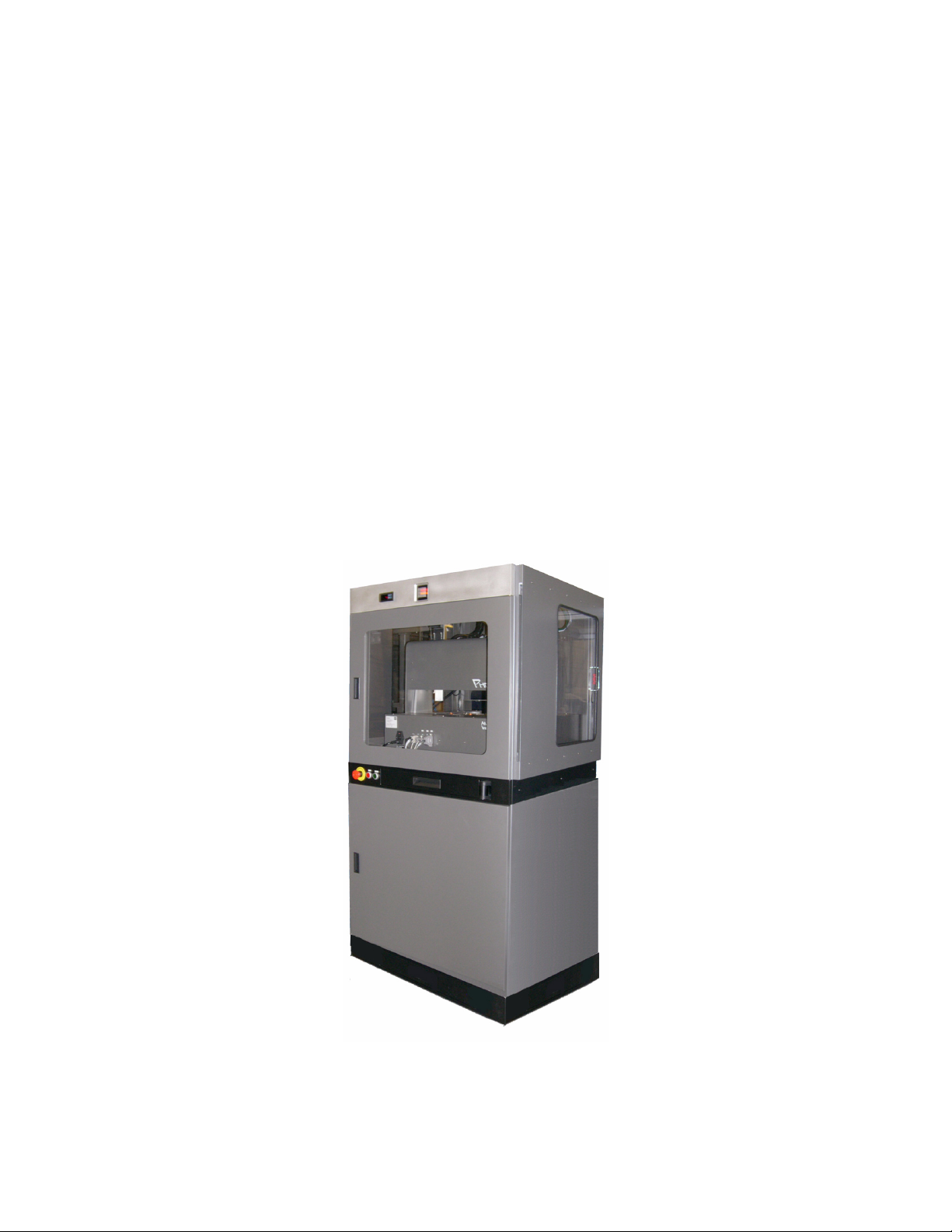
Also known as the Phoenix RE, the Phoenix HT (High Throughput) system is an enclosed station
The Phoenix DT (Desktop) system is a standalone system.
INTRODUCTION
in a CrystalMation system.
1.1. General Description
The Phoenix HT system creates experimental plates using screens contained in deep-well blocks
and protein samples.
A dispense head containing 96 syringes draws specific volumes of chemicals from a deep-well
block and places them in a plate used for protein crystallization experiments (experimental
plate).
A single-channel nano-dispenser draws specific volumes of solution from sample vials and
dispenses them in experimental plates.
The Rigaku software interface acts as an executive for the Phoenix HT system; the Art Robbins
Instruments’Phoenix software can be accessed for maintenance purposes.
Figure 1. CrystalMation Phoenix HT
© 2007–2012 Rigaku Automation, Inc. 1 401718 Rev A
Page 8
Phoenix HT User Manual
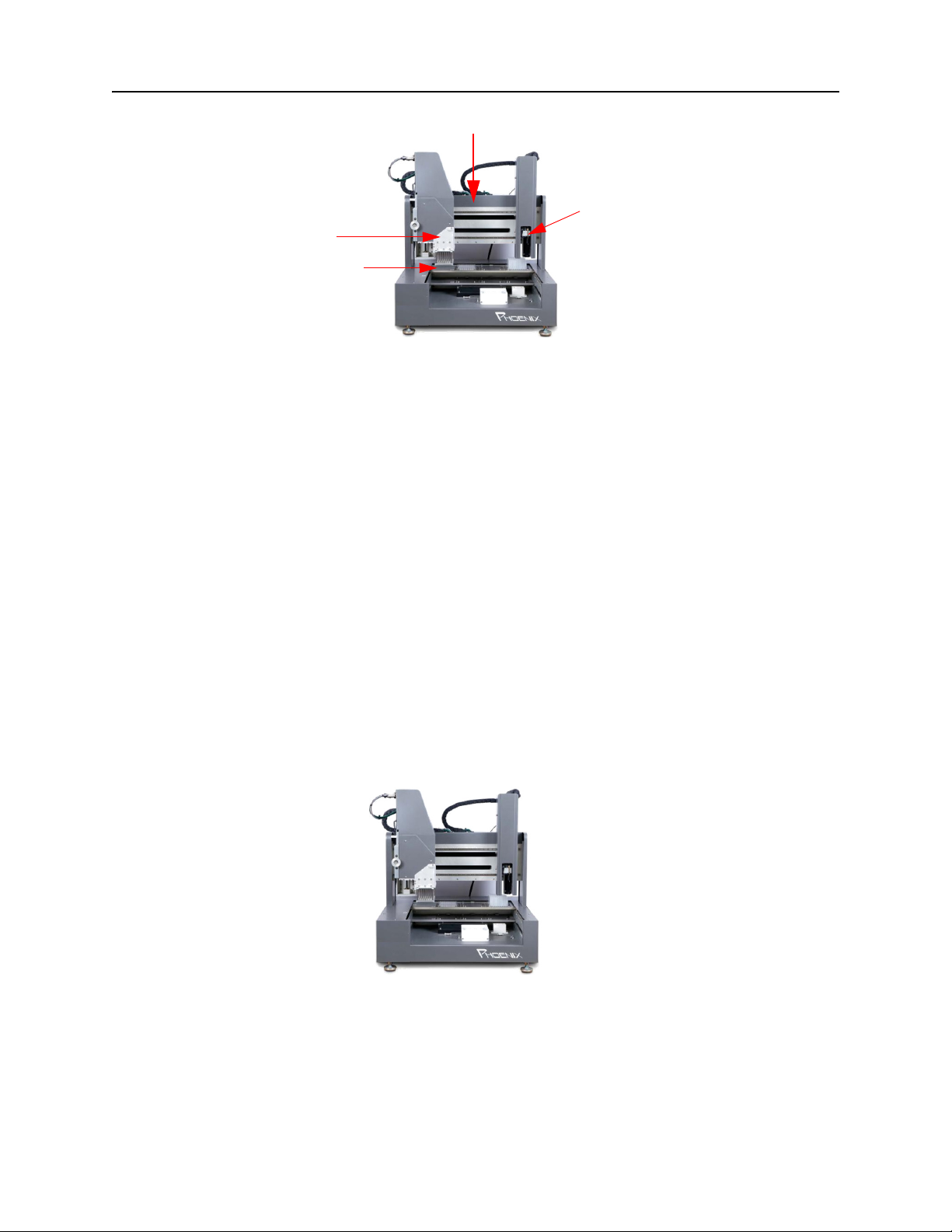
P h o e n i x B a s e S y s t e m
96-Syringe
Dispense
Head
Plate Deck
Figure 2. Phoenix Base System
A Phoenix HT system is part of a CrystalMation system.
Functions included with a CrystalMation Phoenix HT system are:
An enclosure to contain the entire system.
An Emergency Motor Off (EMO) button to stop the motors immediately in an emergency.
Start and Stop buttons.
An active nest, to precisely and automatically position an experimental plate.
An antistatic curtain, to reduce static electricity that can interfere with drop placement.
A protein chill block, to chill vials of protein or other substances.
Dual chimney wash station.
1.2. Phoenix HT System Major Components
Nano-Dispenser
The Phoenix HT instrument consists of a base Art Robbins’ system and additional components.
1.2.1 Phoenix Base System
Follow all safety cautions and warnings in “1.4. Potential Hazards” on page 9. For cabling and
electrical connections, see “Chapter 2. Installation” on page 10.
Figure 3. Phoenix Base System
© 2007–2012 Rigaku Automation, Inc. 2 401718 Rev A
Page 9
Phoenix HT User Manual
1.2.2 Enclosure Status Light Indicators
The status lights for the Phoenix HT instrument indicate the following conditions.
Color Standard Definition Machine Specific
All Off System has no power
Solid Red Power is on, software launched, software in
Blinking Red Power is on, software launched, system has an
Solid Amber Power is on, software launched, no errors but
Blinking Amber Power is on, software launched, no errors but
Solid Green Power is on, software launched, no errors,
Blinking Green Power is on, software launched, no errors, system
Blinking
Amber+Red
stopped state, or machine is not ready to process
orders. Machine can not start processing orders.
error condition and system has stopped, or the
system requires initialization, or the EMO is active.
supplies are low and system will run out and stop
soon, or the temperature is out of specification.
system has run out of supplies and stopped, or the
software is paused, or the doors are open or
unlocked.
software is in idle state, waiting on orders. The
machine will automatically process orders when
they become available.
is running, actively processing/moving.
Power is on, software is not launched or control
system is not responding.
Stopped, not ready for plate to be
made.
Not initialized, EMO pressed,
liquid handling error.
Supplies low.
Software paused, door open, low
water pressure.
Idle, waiting on orders.
Order being processed.
Application software not
connected.
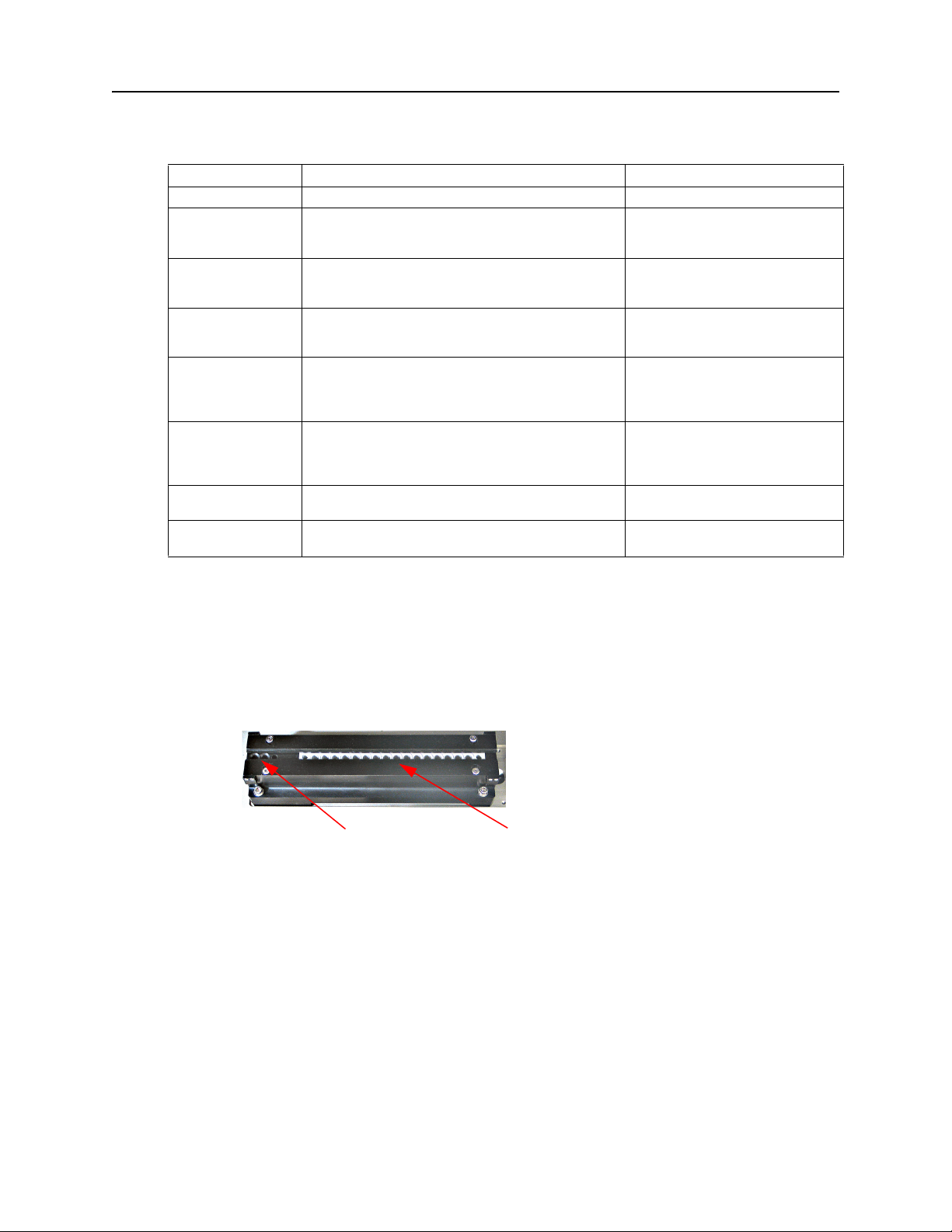
1.2.3 Protein Chiller Block
The protein chiller block uses a thermo-electric temperature controller to maintain a user-specified
temperature to prevent denaturation of protein samples. There are 16 temperature-controlled slots
and 2 slots that are not temperature-controlled, or ambient temperature. Each slot holds a 200
µl
PCR tube. The temperature is set using the interface on the thermo-electric control unit (Figure 3).
1 2 3 4 5 6 7 8 . . . . . . 16 Slot Numbers
Ambient temperature slots
Temperature-controlled slots
Figure 4. Protein Chiller Block
© 2007–2012 Rigaku Automation, Inc. 3 401718 Rev A
Page 10
Phoenix HT User Manual
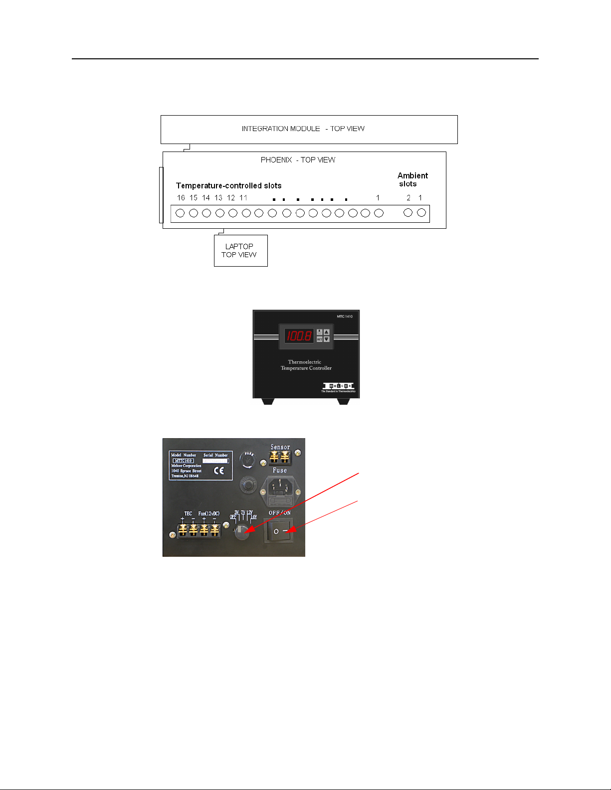
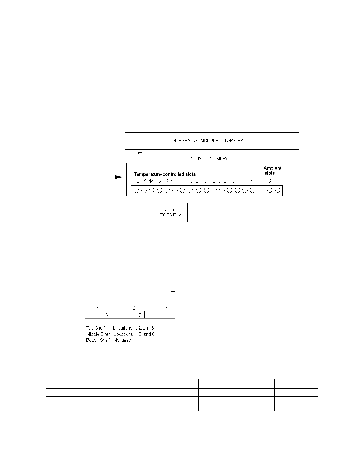
In the Phoenix HT enclosure, when accessing the the chiller block through the left-side access
window, the location numbers are in reverse order because the Phoenix system faces the
Integration Module.
Figure 5. Phoenix HT Chiller Block Slots
Figure 6. Temperature Controller Front Panel
Always set to 7 V
Click to power ON.
Figure 7. Temperature Controller Rear Panel
To apply power to the Protein Chiller Block, flip the rocker switch on the back of the box labeled
Thermoelectric Temperature Controller underneath the deck.
To adjust the temperature, push and hold the SET button until the number on the display begins
flashing. Use the arrow keys to adjust the temperature setting. Push SET when the desired
setpoint is reached.
© 2007–2012 Rigaku Automation, Inc. 4 401718 Rev A
Page 11
Phoenix HT User Manual
1.2.4 Wash Stations
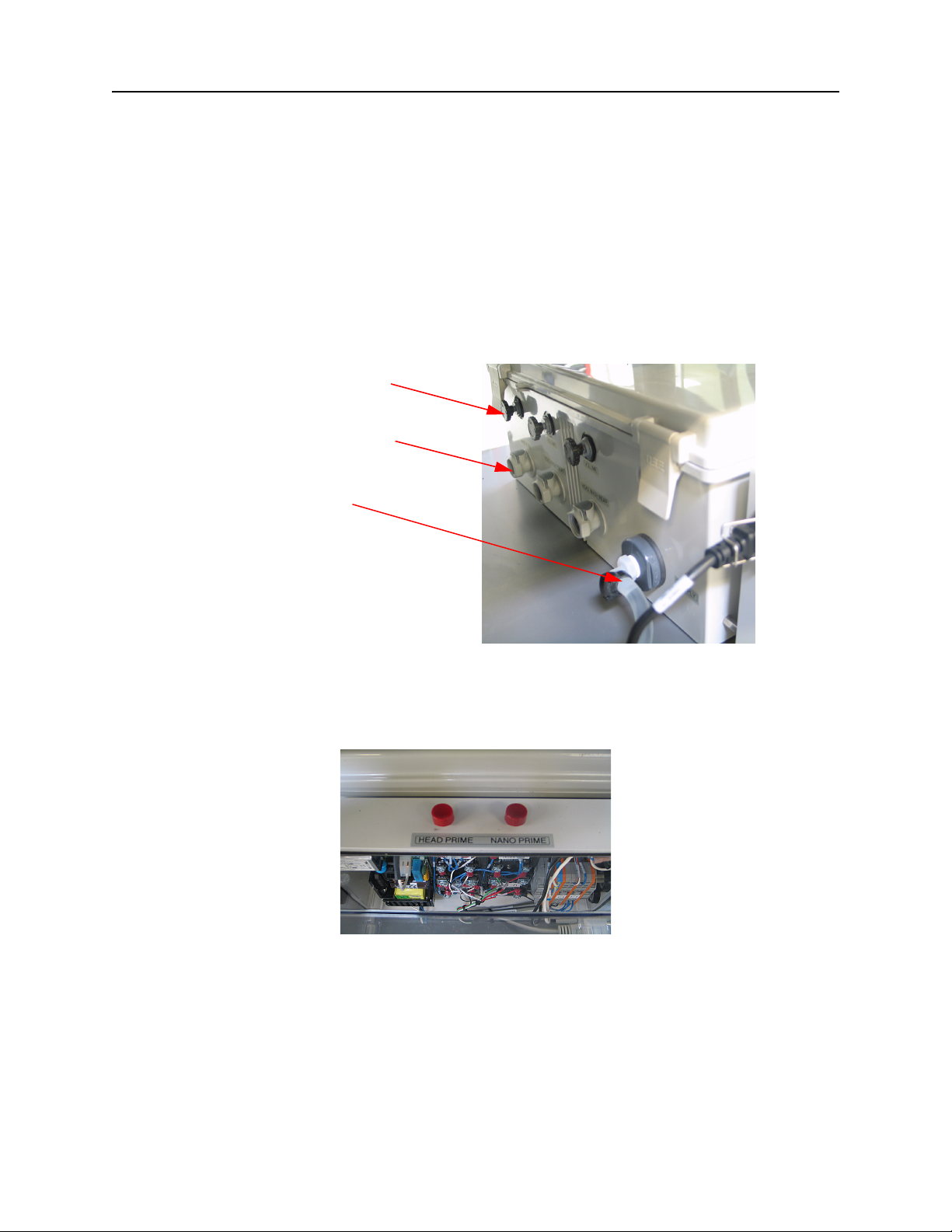
The 96-head wash station and the nano wash station are supplied with wash water from the water
pump control box. The pump control box controls the flow of the wash water.
Water enters the controller from the water pump control box, and is pumped through one line
to the nano-wash station, and through two lines to the 96-head wash station.
The three lines are controlled by three valves.
Located on the right side of the water pump control box, push buttons prime the pumps, a
process that removes air in the lines and allows free water flow.
Waste water from the wash station chimneys flows from the wash station drain directly to a
waste-water tank.
Flow control valves
Water lines to wash stations
Water line from supply
Figure 8. Water Pump Control box (Front)
Located on the right side of the pump control box, push buttons on the electronics control box
prime the pumps, a process that removes air in the lines and allows free water flow.
Figure 9. Buttons to Prime the Pumps
© 2007–2012 Rigaku Automation, Inc. 5 401718 Rev A
Page 12
Phoenix HT User Manual
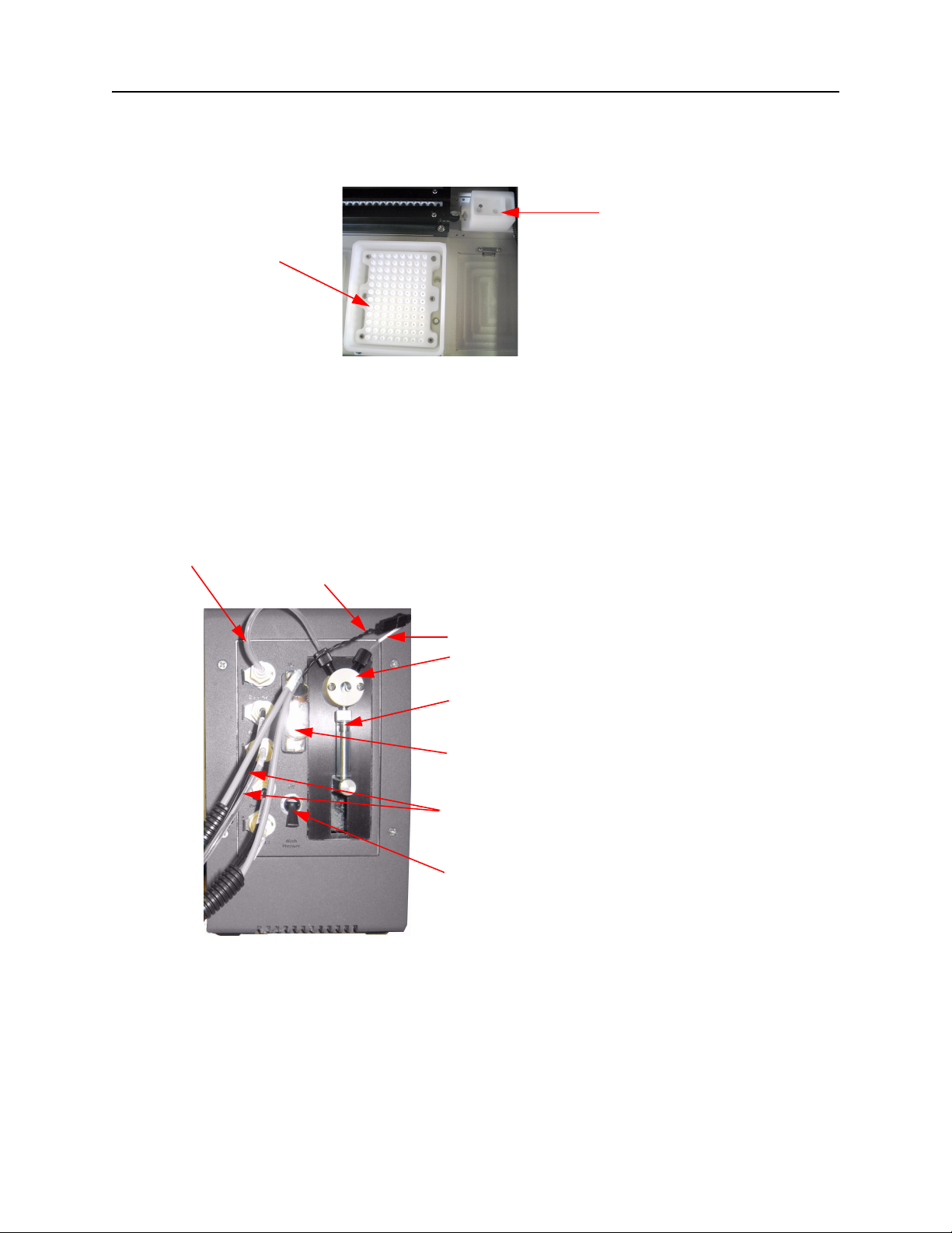
The 96-head wash station has 96 channels, one for each needle in the 96-dispenser head, to
increase wash efficiency and eliminate cross contamination. The wash station is mounted on
the deck in Slot 8.
Nano wash station
96-head wash
station chimney
chimney
Figure 10. Wash Station Chimneys
The nano wash station is a wash station for the single-tube head, to increase wash efficiency and
eliminate cross contamination.
1.2.5 Nano-Dispense Controller
Located inside the enclosure, the nano-dispense controller dispenses the precise nano-liter drops
of protein or other samples.
Clear wash supply line to the switching valve
Black line tip trigger that opens and closes the nano dispenser tip
Supply line to the nano dispenser tip
Switching valve between washing/aspirate and
dispensing functions
Syringe used to dispense/aspirate
Electrical connector which provides the black line tip
trigger and two grey lines used as level sensors for the
reservoir bottles
Each reservoir bottle has a black line to pressurize and
a clear reagent line to supply wash fluid from the
reservoir bottles
Switch to unpressurize the reservoir bottles to fill
them, and then pressurize them
Figure 11. Nano-Dispense Controller, Front
© 2007–2012 Rigaku Automation, Inc. 6 401718 Rev A
Page 13
Phoenix HT User Manual
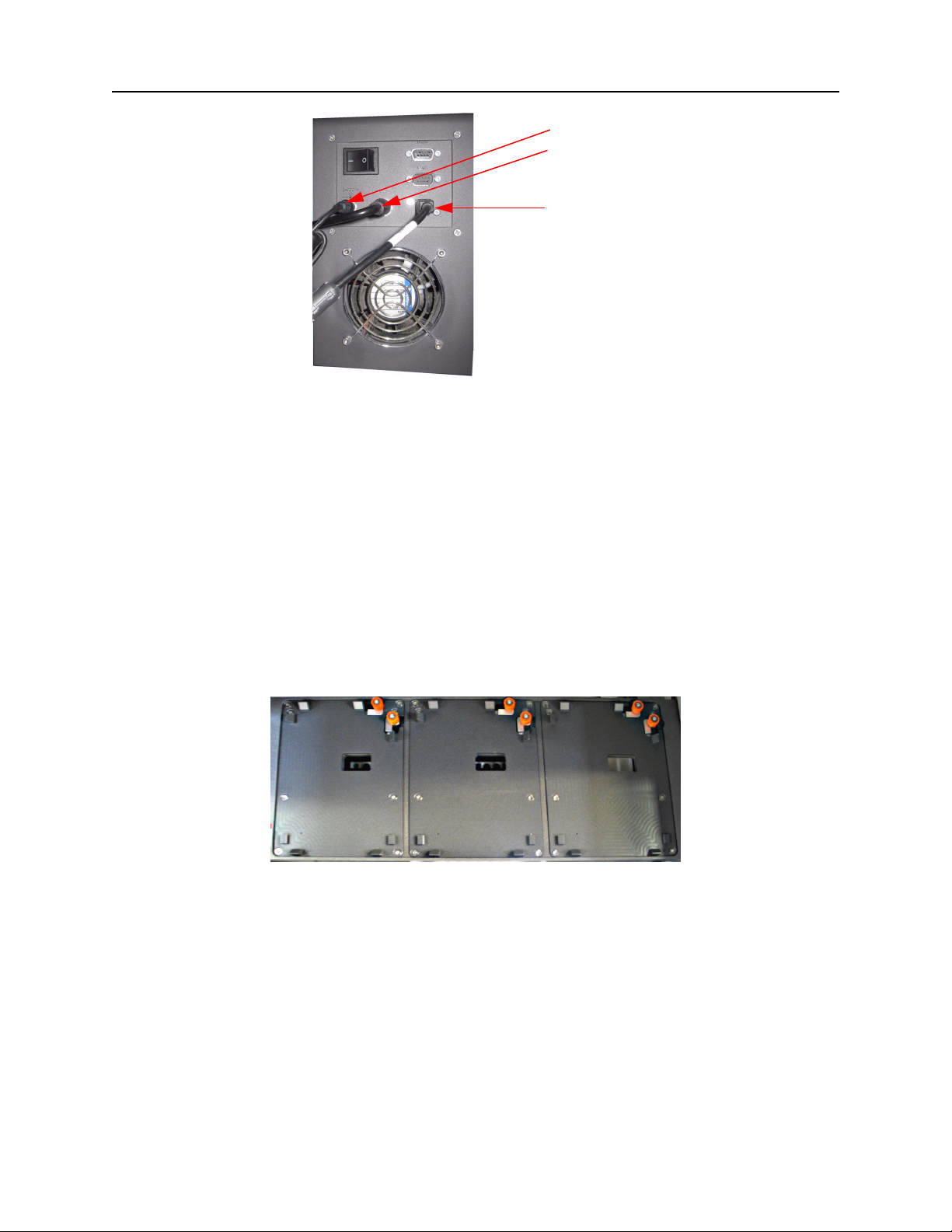
Cable to power supply adapter
Nano trigger connection to Phoenix
base system rear panel
USB cable to computer
Figure 12. Nano-Dispense Controller, Rear
1.2.6 Anti-Static Bar
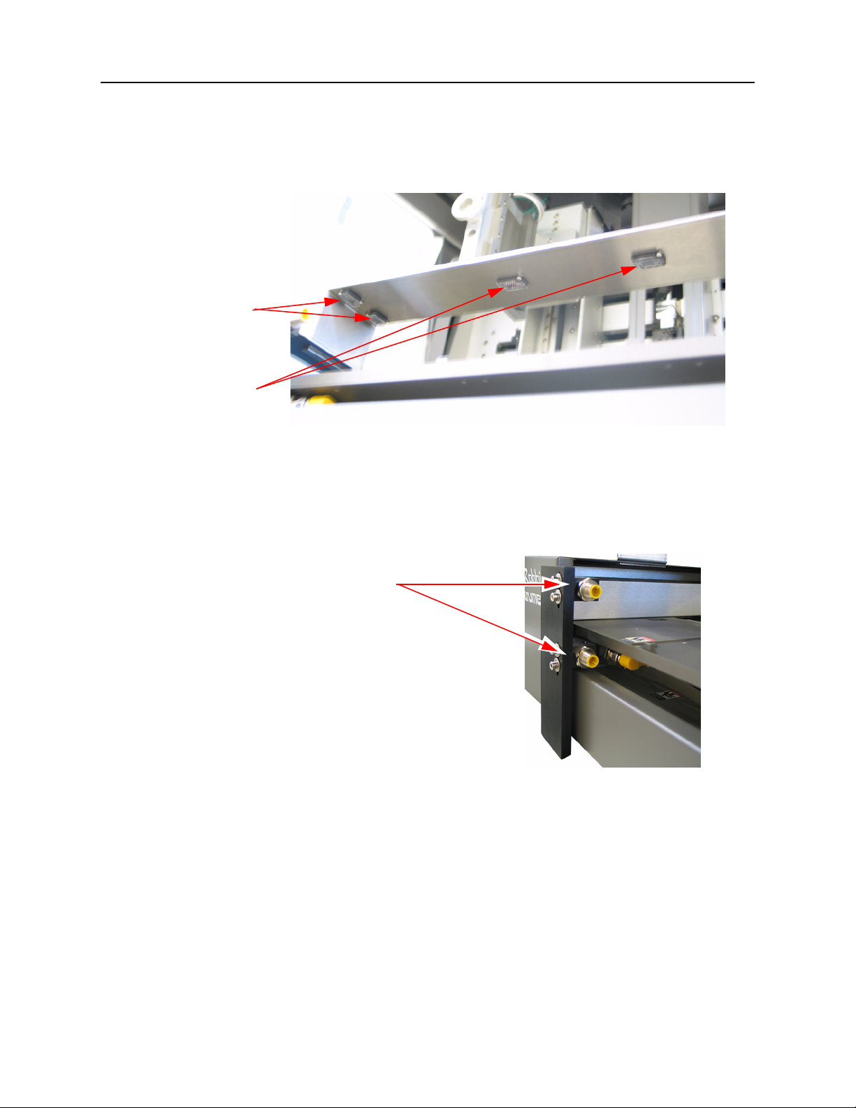
The anti-static bar removes static electricity from crystallization plates before use. Static electricity
can cause the dispense drops to shift inside the subwells. Static charges are removed from plates
that pass in proximity to the anti-static bar.
1.2.7 Active Nest
An Active Nest positions a plate against the indexing pins under software control for accurate
dispensing. The shelf must be in the front position and contacting the electrical pins in order to
complete the software command to open the active nest. Flexinol® wires are activated to pull two
rollers in the upper right corner away from the center of the nest. When the rollers close, the plate
is pushed against the indexing pins. The active nest is normally in the closed position.
Figure 13. Active Nests
© 2007–2012 Rigaku Automation, Inc. 7 401718 Rev A
Page 14
Phoenix HT User Manual
1.2.8 Plate and Shelf Sensors
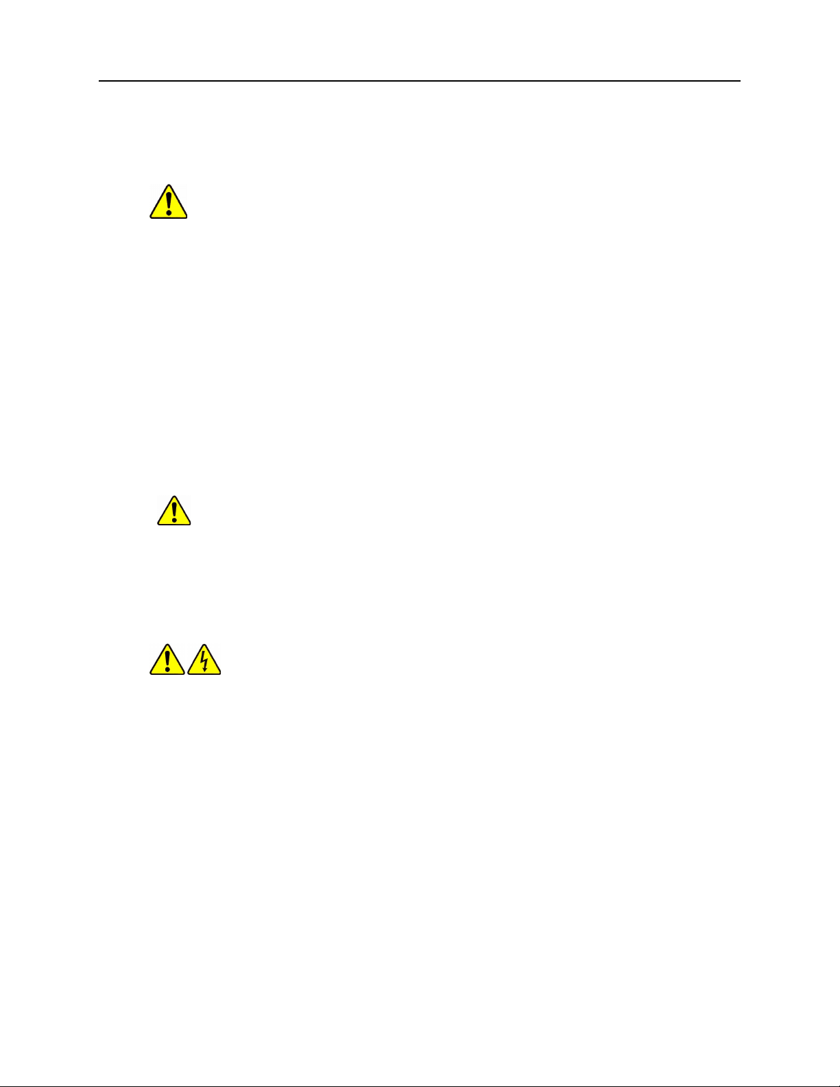
A sensor bar over the shelves holds the plate sensors and the shelf sensors. The shelf sensors
determine whether the upper or lower shelf is in the sensing position. Plate sensors determine
whether a plate is present in a specific position on a shelf.
Shelf
position
sensors
Plate sensors
Figure 14. Sensor Bar for Plate and Shelf Position Sensors
1.2.9 Active Nest Terminals
The Active Nests, if installed, can receive commands only when the terminals on the shelf are in
contact with the terminals on the front of the base unit.
Terminals for active nests
(lower shelf terminals are connected)
1.3. Safety Features
The basic safety features that have been designed into the system include:
Servo motors tuned for safety
Figure 15. Active Nest Terminals
Grounded power supply system
Enclosed work area (CrystalMation system only)
Access door interlocks (CrystalMation system only)
© 2007–2012 Rigaku Automation, Inc. 8 401718 Rev A
Page 15
1.4. Potential Hazards
The following areas of operation may be associated with hazards to persons and equipment.
Contact the Rigaku Automation Service Department for assistance if you have questions about
safe operation of the instrument.
WARNING: Always disconnect the system from electrical power prior to servicing, cleaning,
or moving this equipment.
Networking
Using the Control Software
Electric power hazards
Moving the Phoenix HT system from cold to warm areas
Opening enclosure access doors
If a failure occurs in the Phoenix HT system, contact the Rigaku Automation Service Department
for failure repair.
1.4.1 Networking
Phoenix HT User Manual
The control computer and the Database Server are networked together. The Database Server can
be connected to an external network.
CAUTION: DO NOT connect the control computer directly to an external network. Make
any external network connection for the Phoenix system through the Database Server.
The control computer is connected via Ethernet to the Database Server.
1.4.2 Electric Power Hazards
The Phoenix HT system operates using 100-240 VAC. Keep any moisture or foreign objects out of
the enclosures. Do not apply power to the equipment in wet environments or when moisture may
have entered the equipment.
WARNING. Risk of Electrical Shock. DO NOT open the electrical enclosure. The
electrical enclosure is a factory service item ONLY.
1.4.3 Moving the Phoenix HT System from Cold to Warm Areas
Condensation may form on interior surfaces when the equipment is moved from a cold room to a
warm room. Ensure that the equipment has reached ambient temperature before operating.
1.5. Rigaku Service and Support
Our in-house service personnel and application scientists back our field service force; we are
ready to serve you.
Contact us through the help desk, email, or online requests.
Service help desk
General: 1-888-362-2324 (answered 24/7) [281-362-2300 x 132]
European-based single-crystal customers: +(44) 1732 765 008
By e-mail:
General: [email protected]
© 2007–2012 Rigaku Automation, Inc. 9 401718 Rev A
Page 16

Phoenix HT User Manual
European-based single-crystal customers: [email protected]
Online service request form: Located on http://www.rigaku.com/contact/service.htm
If the system fails, note what happened, any messages that appear on the monitor, lamp displays,
what the system was doing before the failure, and any steps that were taken to correct the
problem. Then contact the Rigaku Automation Service Department for assistance.
© 2007–2012 Rigaku Automation, Inc. 10 401718 Rev A
Page 17

CHAPTER 2. BASICS
This chapter contains instructions for setting up, starting and shutting down the system. The
Phoenix HT system creates experimental plates using screens contained in deep-well blocks and
protein samples.
The 96-syringe dispense head is used to transfer an 8x12 array of solutions simultaneously.
For protein crystallography, it is used for transferring a crystallization screen from a deep well
block into the reservoirs of an experimental plate.
The nano-dispenser aspirates from a single source location and dispenses a small volume to
many locations. For protein crystallography, it is used to aspirate protein from a sample tube
and dispense drops into the experimental plate.
For basic setup, starting, and shutting down procedures as well as status light usage, see:
“Appendix B. Facilities Layout and Cabling” on page 40
“2.1. System Power-On” on page 11
“2.2. Shutting Down the System” on page 12
“2.3. Running the System” on page 12
“2.4. Status Light Indicators” on page 12
“2.5. Using the Stop, Start, and Emergency Stop (EMO) Pushbuttons” on page 13
“2.6. Resetting the System after an Emergency Motor Off (EMO) Shutdown” on page 13
2.1. System Power-On
The power-up sequence for the CrystalMation Phoenix HT instrument follows:
1. Rock the power switch on the outside of the enclosure to the | position.
2. Power on the control laptop computer and log into Windows.
3. Power on the Phoenix HT base system using switch on the back.
4. Power on the Nano-Dispense Controller.
5. If applicable, power on the temperature controller.
6. Start the Rigaku Phoenix HT software. (The Art Robbins’ Phoenix software is automatically
started.)
7. Twist the red Emergency Motor Off (EMO) button to reset the system.
8. Push the lit green Start button to reset power.
9. Click the green icon in the Phoenix HT software to home the motors in the instrument.
When the motors are homed, the instrument is ready for processing.
© 2007–2012 Rigaku Automation, Inc. 11 401718 Rev A
Page 18

Phoenix HT User Manual
2.2. Shutting Down the System
The power-down sequence for the CrystalMation Phoenix HT instrument is:
1. Click the Disconnect icon in the Phoenix software.
When asked if you wish to disconnect from the Phoenix RE software, click OK.
When asked if you wish to disconnect from the Art Robbins Phoenix software, click OK.
2. Push the red Emergency Motor Off (EMO) button.
3. Power off the Nano-Dispense Controller.
4. Power off the Phoenix HT instrument.
5. Shut down the laptop computer via Windows.
6. Rock the power switch on the outside of the enclosure to the 0 position.
2.3. Running the System
Follow the operating procedures current in your laboratory setting. Refer to the guidelines and
instructions in the original-equipment Phoenix Setup Guide, in “Chapter 3. Quick Start Procedures”
on page 14, and in the “Chapter 4. Phoenix HT Application Reference” on page 19 of this manual.
2.4. Status Light Indicators
The status lights for the Phoenix HT enclosure indicate the following conditions.
Color Standard Definition Machine Specific
All Off System has no power
Solid Red Power is on, software launched, software in
stopped state, or machine is not ready to process
orders. Machine can not start processing orders.
Blinking Red Power is on, software launched, system has an
error condition and system has stopped, or the
system requires initialization, or the EMO is
active.
Solid Amber Power is on, software launched, no errors but
supplies are low and system will run out and stop
soon, or the temperature is out of specification.
Blinking Amber Power is on, software launched, no errors but
system has run out of supplies and stopped, or
the software is paused, or the doors are open or
unlocked.
Solid Green Power is on, software launched, no errors,
software is in idle state, waiting on orders. The
machine will automatically process orders when
they become available.
Blinking Green Power is on, software launched, no errors, system
is running, actively processing/moving.
Blinking
Amber+Red
Power is on, software is not launched or control
system is not responding.
Stopped, not ready for plate to be
made.
Not initialized, EMO pressed, liquid
handling error.
Supplies low.
Software paused, door open, low
water pressure.
Idle, waiting on orders.
Order being processed.
Application software not
connected.
© 2007–2012 Rigaku Automation, Inc. 12 401718 Rev A
Page 19
Phoenix HT User Manual
2.5. Using the Stop, Start, and Emergency Stop (EMO) Pushbuttons
Located on the Phoenix HT enclosure, the Start, Stop, and EMO pushbuttons are used as follows:
EMO Immediately shuts off power to the Phoenix HT instrument, stops movement, and stops
the Art Robbins Phoenix application.
Use the EMO button when there is a danger to the machine or to persons, for example,
if a tall plate is in a short plate slot.
See also “2.6. Resetting the System after an Emergency Motor Off (EMO) Shutdown” on
page 13.
Stop Pauses the Phoenix HT system at the end of the current protocol step.
Performs a “soft” stop, running the instrument until the end of the current protocol step
before stopping.
Start Starts or resumes the sequence.
Restores power after an EMO, and also performs the same functions as the Start button
in the Rigaku Phoenix software.
CAUTION:
stop the machine.
If there is any concern at all about instrument crashing, use the EMO to
2.6. Resetting the System after an Emergency Motor Off (EMO) Shutdown
To reset from an EMO state:
1. Rotate the red EMO button clockwise until it pops out.
2. Push the green push button to restore power. The Phoenix HT application restarts the Art
Robbins Phoenix application.
3. Push the green start button. The Phoenix HT application homes the motors. The Art Robbins
Phoenix application connects.
4. Remove and discard the block that was in process.
5. Perform a wash.
6. In the Jobs View, select the job that was running when the EMO button was pushed.
7. Select Jobs from the menu bar, and select Edit Job. Check the Reset job status check box to reset
the job.
Reset job status
check box
8. To rerun the protocol, load and run the job.
© 2007–2012 Rigaku Automation, Inc. 13 401718 Rev A
Page 20
CHAPTER 3. QUICK START PROCEDURES
This chapter outlines basic steps used with the Phoenix HT system. The preliminary setup
includes the physical positioning and registration of protein samples and the creation of jobs in
Crystaltrak. The Rigaku Phoenix software procedures define the locations of the protein samples,
check for adequate liquid volumes, and enable the running of the Phoenix system .
3.1. Preliminary Setup
1. Open the left-hand access door of the Phoenix HT enclosure and manually insert the sample
tubes into the protein chiller block.
ccessing the chiller block
rom the left-hand access
oor
Note the slot location where you place each tube; for example, slot 16 is the first slot as you
reach into the enclosure.
IMPORTANT: Be sure that the cap to the tube is removed before inserting the tube into the
chill block. Failure to do this can result in damage to the nano dispenser needle.
2. If you are not using the Integration Module to automatically load plates, with the same lefthand access door still open, position a crystallization plate and a deep well block containing
the desired screen into the Phoenix plate nests located on the top two shelves.
If not using the Integration Module, then the manually added plates/block must be registered
in the Manage Device/Onboard plates view.
Table 1. Plates Approved for the Phoenix HT System
Plate Type Plate Catalog Number Barcode Prefix
Single-well Greiner CrystalQuick Low Profile Greiner 609171 or 609871 S0
Multi-well Art Robbins’ Intelliplate 3-well Low Profile
(also known as CrystalMation plate)
ARI 102-0001-13 RZ
© 2007–2012 Rigaku Automation, Inc. 14 401718 Rev A
Page 21
Phoenix HT User Manual
3. You must first set up plate definitions in the Rigaku CrystalTrak application. Once defined,
submit jobs from CrystalTrak to the Phoenix HT as follows:
a single job to the Phoenix HT by clicking Submit Plate in CrystalTrak
multiple jobs by setting up and clicking Batch Load in CrystalTrak
NOTE: The detailed protocol for the Phoenix HT is created independently by Rigaku, and is
not created using the Art Robbins’ Phoenix application. The protocol used on the Phoenix HT
system is installed on the Phoenix HT laptop application prior to delivery, and is
automatically used by the Phoenix system.
4. For any desired modification to this protocol, please contact Rigaku Service.
3.2. Phoenix HT Software Procedures
The following procedure registers the protein samples in the Phoenix system, checks for adequate
liquid volumes, and enables the running of the Phoenix system
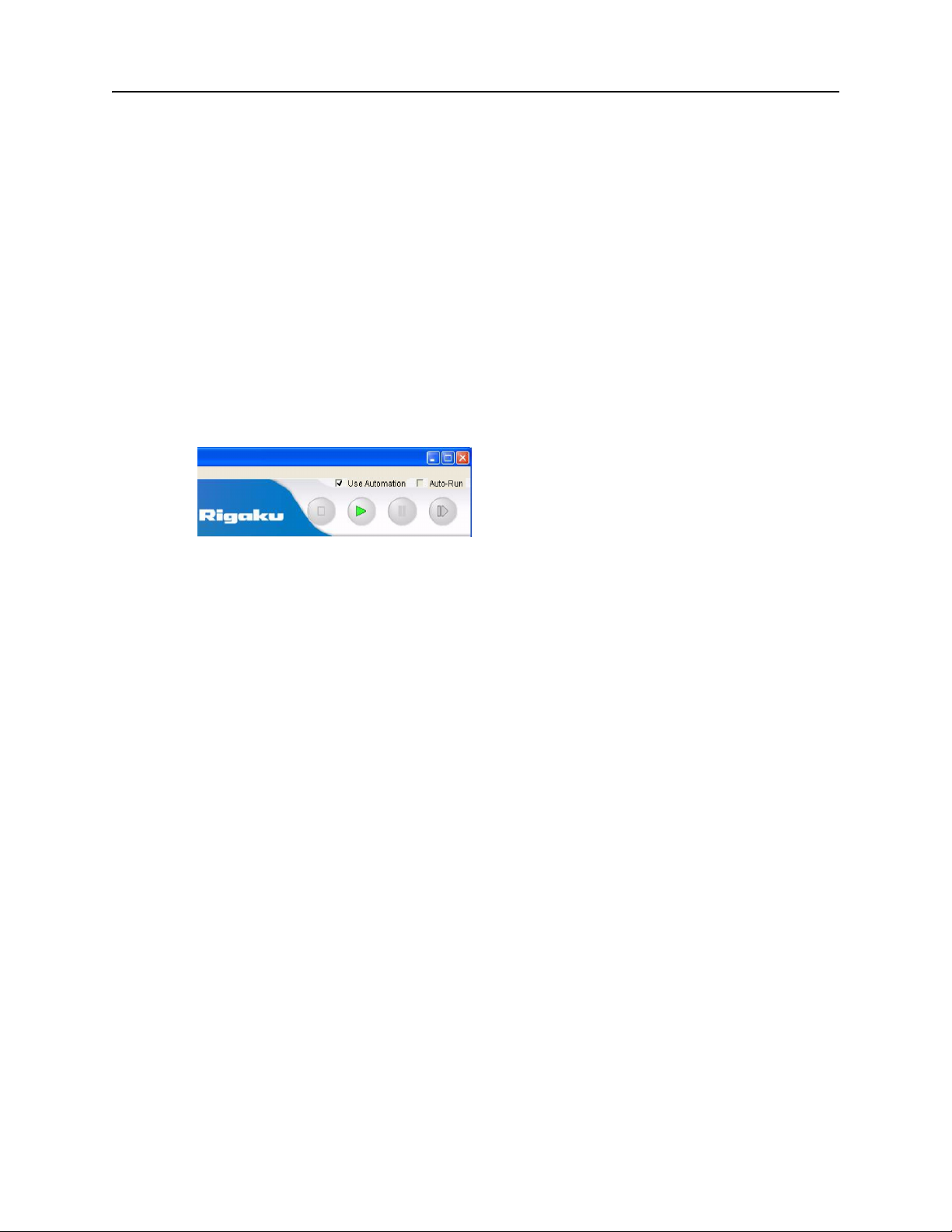
1. Open the Rigaku Phoenix application, and click the Use Automation checkbox .
The connection checks the Integration Module’s inventory for the materials required to
execute the job:
Empty crystallization plate of the specified type (see Table 1 on page 14)
Filled blocks containing the required screen
TIP Leave the Auto-Run box unchecked until all job requirements in this procedure have been
met.
2. Select the job to be run and highlight the Task to be processed. If there is more than one task,
select the first one in the list.
A set of parameters and messages appears in the Details pane, and unregistered samples are
highlighted in RED text.
TIP The Details messages timeout after a few seconds in order to ensure immediate status
updates. To refresh the messages, click on the related Task which you want to review.
NOTES: If you skip step 2, you will not be able to process the next series of steps.
If the Task list is not visible, pull the bottom edge of the Jobs panel until it appears.
IMPORTANT To delete a single-task job, select the Job and click Delete. DO NOT delete the
task of a single-task job; otherwise, the job becomes frozen in place.
© 2007–2012 Rigaku Automation, Inc. 15 401718 Rev A
Page 22
Phoenix HT User Manual
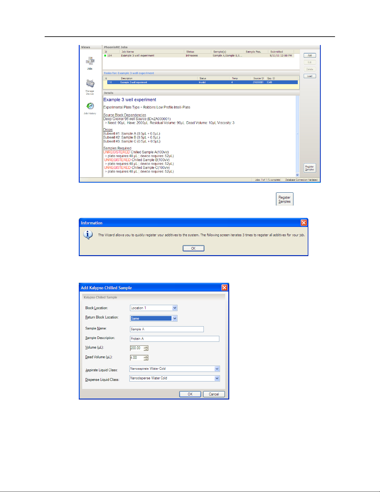
3. To register the sample(s) on the deck, click the Register Samples button in the lower
right-hand corner of the window and click OK when a message to register additives appears.
4. For each sample of the three samples in this example job, select the appropriate entry for each
field, then click OK.
Block Location:
Return Block Location:
The slot location of the sample in the chiller block.
The slot location for the residue returned (the purge back over the
aspirated sample.
© 2007–2012 Rigaku Automation, Inc. 16 401718 Rev A
Page 23
Phoenix HT User Manual
Sample Name:
Sample Description:
Name given to the sample
Description of the sample, often the chemical composition
Volume (uL): The initial volume in the sample tube to be valid for use must include the extra
volume required for the overaspirate.
Dead Volume (uL):
Aspirate Liquid Class:
Dispense Liquid Class:
This volume specifies the overaspirate volume which is added to the
aspirated sample volume.
Select a pre-defined liquid class appropriate to your sample. Most often
Nanoaspirate Water Cold is used.
Select a pre-defined liquid class appropriate to your sample. Most often
Nanodispense Water Cold is used.
The application checks that the Volume provided is adequate for the job requirements of the
sample volume plus the overaspirate (dead) volume.
NOTE: Depending on the nano dispenser provided with your Phoenix, the liquid classes may
vary or additional ones may be added. Consult your Rigaku Service representative for the
latest liquid classes available.
5. Verify that all protein samples have been added.
IMPORTANT: Verify that all caps have been removed from all protein sample tubes or the
caps will interfere with the accurate dispensing of liquids and the job will fail.
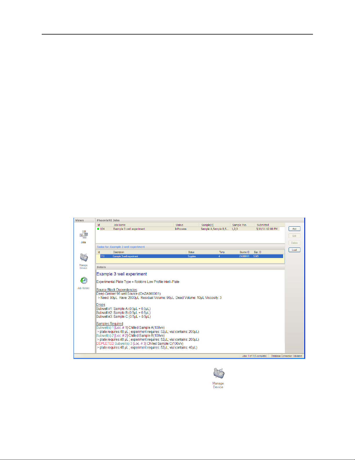
Review the Details pane for RED text which indicates supply issues. In the below example, the
DEPLETED message indicates a shortage of liquid for Sample C in subwell 3. Note that the
Job Status is In Process and the Task Status is Supplies.
6. To fix the supply problem, click on the Manage Device view and click the Chilled Block
tab.
Double-click on the deficient sample tube or click Edit.
© 2007–2012 Rigaku Automation, Inc. 17 401718 Rev A
Page 24

Phoenix HT User Manual
Add sufficient volume to the tube in the Edit Kalypso Chilled Sample dialog box and click
OK.
Be sure to physically increase the sample volume in the sample tube to match the edited
volume in the software.
7. When the task(s) are ready to run:
1 Go to the Jobs view, select the Task, and click Load.
2 Click the Green Run button at the top of the window to run one task or job.
or
To automatically run a series of selected jobs and tasks, click the Auto-Run checkbox at the
top of the window.
TIP Due to the initial time delay of large jobs, many customers prefer to initially click the Run
button for the first job and a quick response to ensure that the system is fully operational, then
click the Auto-Run checkbox which processes all jobs selected in the Jobs list.
© 2007–2012 Rigaku Automation, Inc. 18 401718 Rev A
Page 25
CHAPTER 4. PHOENIX HT APPLICATION REFERENCE
The Phoenix HT system is controlled by Phoenix HT software. This chapter describes the operator
interface with the following topics:
“Organization” on page 19
“File Menu” on page 20
“View Menu” on page 20
“Jobs Menu” on page 20
“Tools Menu” on page 21
“Views Pane and Icons” on page 23
4.1. Organization
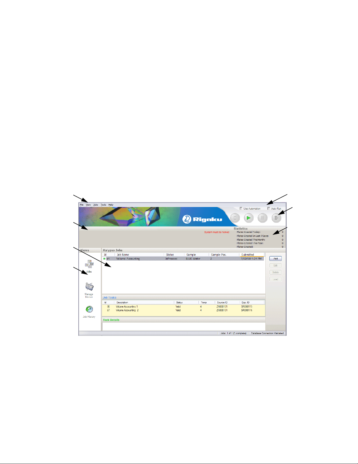
The Phoenix HT application is organized into groups of related functions. The main operator
interface contains menus, integration controls, run controls, a system message area with plate
statistics, and an active view area controlled by buttons in a navigation panel.
Menus
System
message
area
Active
view
Navigation
panel
The Phoenix HT contains the File, View, Jobs, Tool and Windows menus.
Integration
controls
Run
Controls
Plate
statistics
Figure 1. Phoenix HT Application Main Window
© 2007–2012 Rigaku Automation, Inc. 19 401718 Rev A
Page 26
4.2. File Menu
The File menu contains the command to Exit the application. You may also exit the application by
clicking the red button with the white X in the upper right of the window.
4.3. View Menu
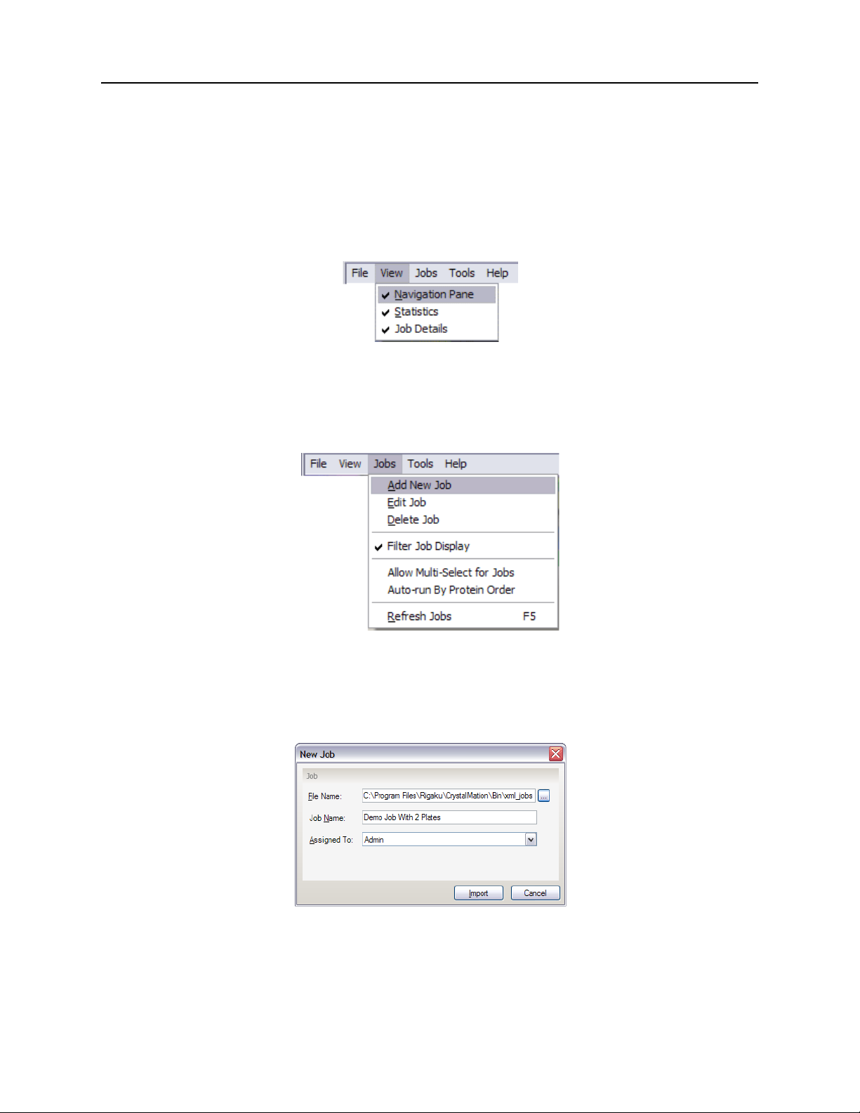
The View menu displays or hides the navigation pane, the plate statistics, and the details section at
the bottom of the Jobs active view.
4.4. Jobs Menu
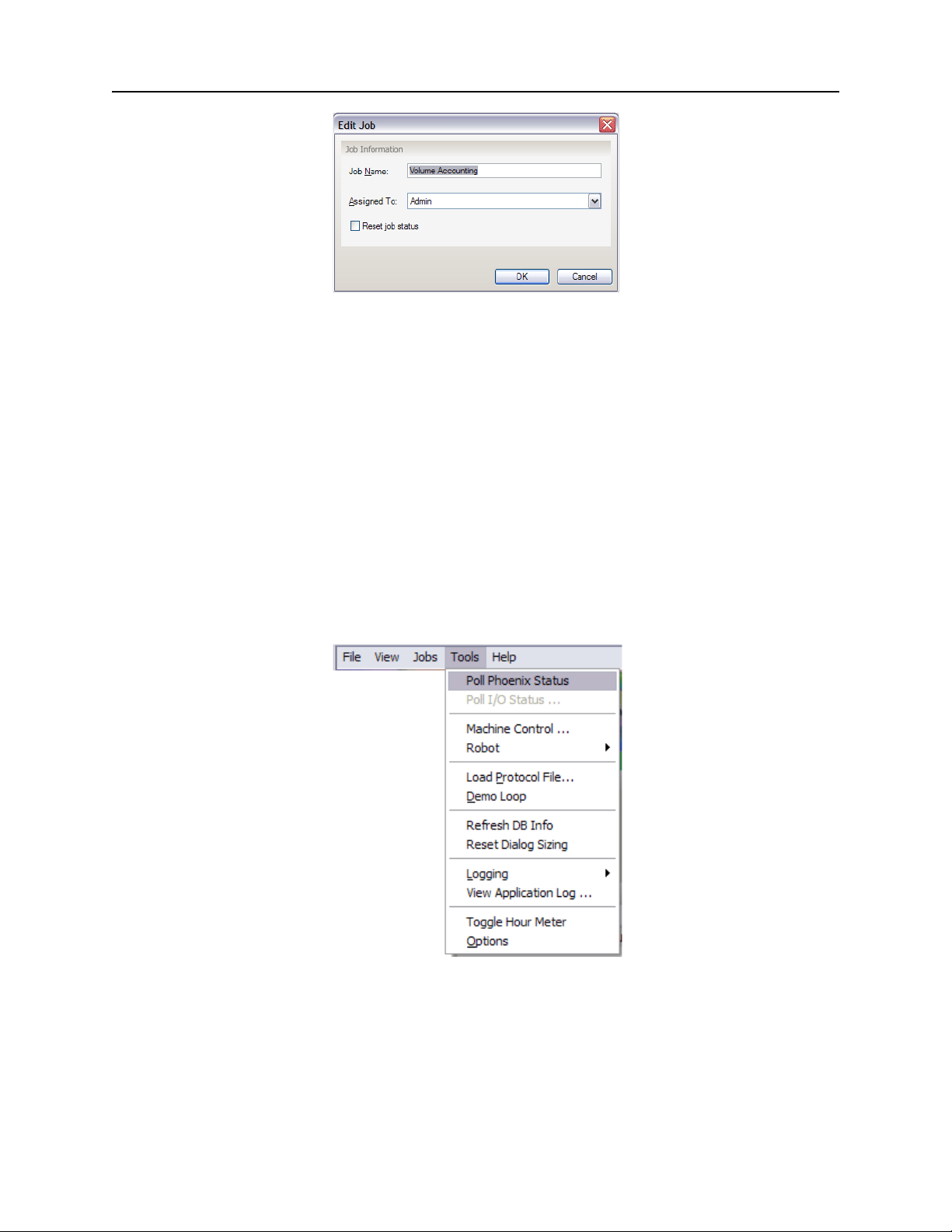
The Jobs menu contains selections adding, editing, deleting, displaying and running jobs.
Phoenix HT User Manual
Figure 2. View Menu
Figure 3. Jobs Menu
Add New Job: Opens the New Job dialog to add a job to the list. Click the button to the right of
the File Name box for a file-open dialog to navigate to and open the job file. Enter the name in
the Job Name box. Choose the job owner from the Assigned To list.
Figure 4. New Job Dialog
Edit Job: Opens the Edit Job dialog to add a job to the list. Edit the name in the Job Name box.
Choose the job owner from the Assigned To list. Check the Reset job status check box to reset the
job status.
© 2007–2012 Rigaku Automation, Inc. 20 401718 Rev A
Page 27
Phoenix HT User Manual
Figure 5. Edit Job Dialog
Delete Job: Deletes the selected jobs.
Filter Job Display: When using two or more Phoenix HT instruments, click to show jobs that
use samples registered with the current instrument. If a sample is not registered with the
current instrument, no jobs that use that sample are displayed.
Allow Multi-Select for Jobs: Check to allow you to select multiple jobs in the Jobs view.
Auto-Run by Protein Order: Runs the jobs in the list in order of the proteins.
Refresh Jobs: Displays the current jobs in the active view.
4.5. Tools Menu
The Tools menu contains commands for performing various application support and maintenance
functions.
CAUTION Use inputs from Rigaku Service to modify any parameters in the Tools menu.
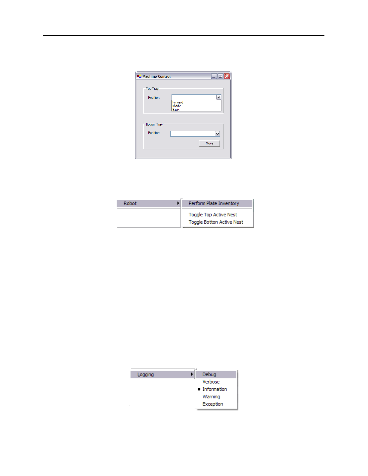
Figure 6. Tools Menu
Poll Phoenix Status: Displays the status of the Phoenix HT in the system message area.
Poll I/O Status ...: Displays the status of the Phoenix HT inputs and outputs in the system
message area.
© 2007–2012 Rigaku Automation, Inc. 21 401718 Rev A
Page 28
Phoenix HT User Manual
Machine Control ...: Displays the Machine Control dialog to move the top and bottom trays.
Click the Position box to show the menu. Choose the Forward, Middle or Back position from the
menu and click the Move button to move the tray.
Figure 7. Machine Control Dialog
Robot: Performs functions with the upper and lower plate shelves in the base system. The
shelves must be moved to the front, under the sensor bar, to perform these functions.
Figure 8. Robot Selections
The selections are:
Perform Plate Inventory: This procedure senses whether a plate is at a particular position.
The barcode and other identifying functions are in other sections.
Toggle Top Active Nest: Toggles the active nests in the upper shelf from the current state. If
the active nests were closed, this selection opens the active nests. The shelf must be in the
forward position. Performs no action if the active nests are not installed.
Toggle Bottom Active Nest: Toggles the active nests in the lower shelf from the current state.
If the active nests were closed, this selection opens the active nests. The shelf must be in
the forward position. Performs no action if active nests are not installed.
Refresh DB Info: Refreshes the display with the latest information from the database.
Reset Dialog Sizing: Resets dialog boxes to their default sizes.
Logging: Provides choices for the information that is captured to the log file. The default
choice is recommended for most applications. Other choices are available for specific uses.
Figure 9. Logging Selections
© 2007–2012 Rigaku Automation, Inc. 22 401718 Rev A
Page 29
Phoenix HT User Manual
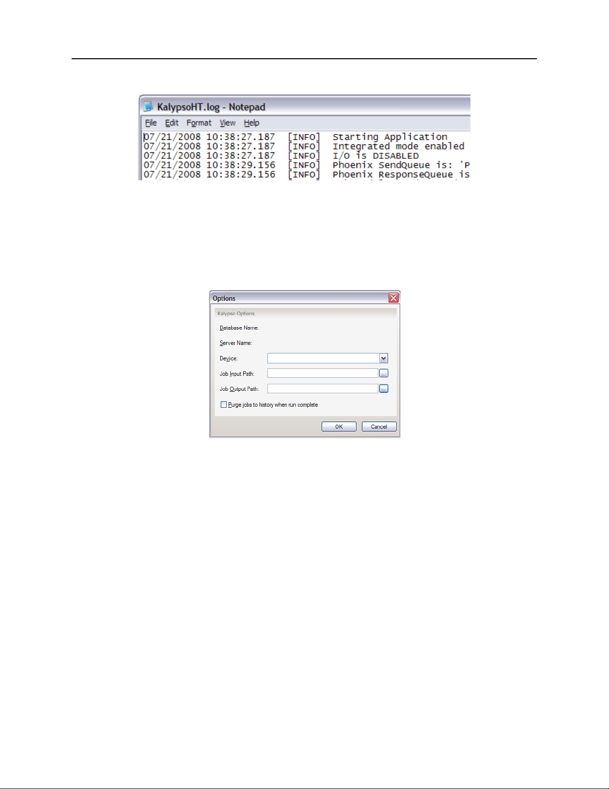
View Application Log: Displays the application log as a separate text file.
Figure 10. Sample Application Log
Toggle Hour Meter: Click to stop or start the count on the hour meter.
Options: Displays the Options dialog. The database and server connected to the Phoenix HT
are displayed in the Database Name and Server Name sections. Select the default input and
output paths for jobs in the Job Input Path and Job Output Path boxes. Check the Purge jobs to
history when complete box to purge jobs from the active view and save them in a history folder.
Figure 11. Options Dialog
4.6. Help Menu
The Help menu contains the About ... selection to display the version number of the Phoenix HT
application and other data.
4.7. Views Pane and Icons
The buttons in the navigation panel display the views: the list of jobs with the Jobs button, the
devices with the Manage Devices button, and previous jobs with the Job History button.
4.8. Jobs View
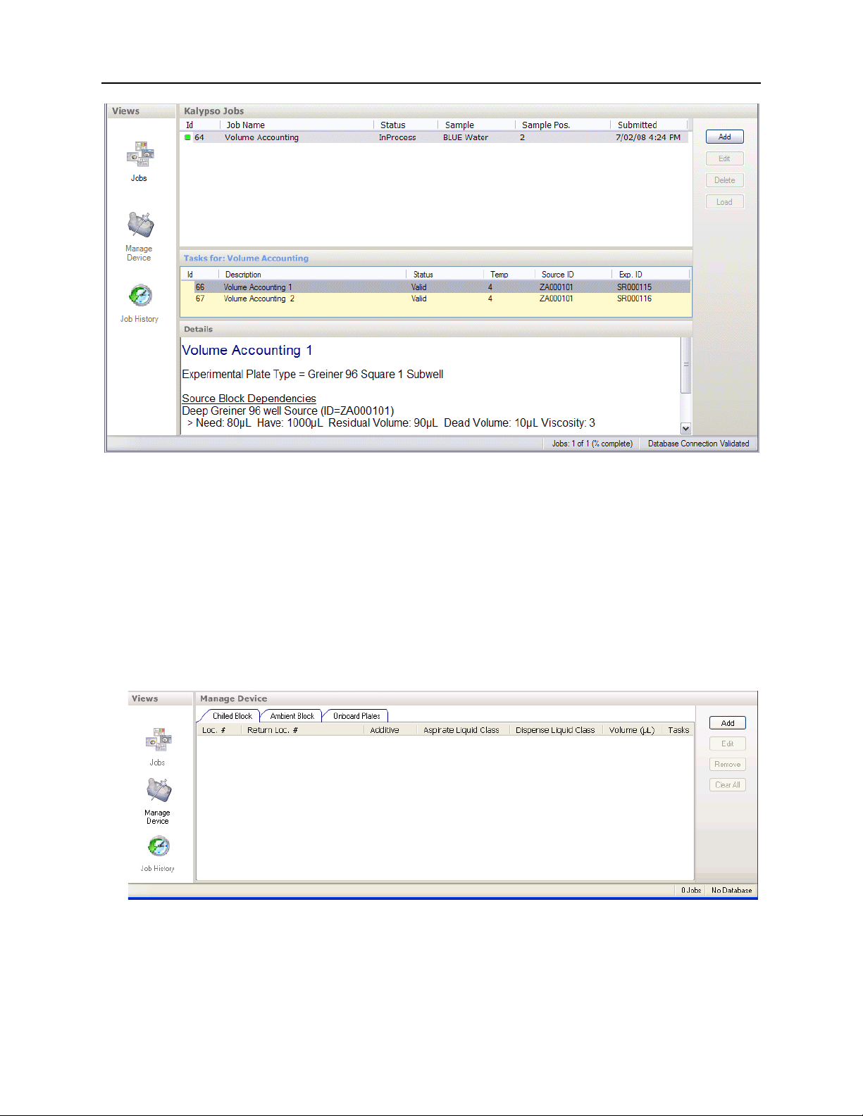
The Jobs view lists the jobs queued for execution in the top list. The tasks for the highlighted job
are displayed in the middle window. Details of the highlighted task are displayed in the lower
window. The Add button opens a Windows Open dialog to locate and add a job to the list.
© 2007–2012 Rigaku Automation, Inc. 23 401718 Rev A
Page 30
Phoenix HT User Manual
4.9. Manage Device View
The Manage Device view displays the solutions in the chilled blocks and ambient blocks of the
protein chiller, and the plates currently assigned on the shelves.
4.9.1 Chilled Block and Ambient Block Tabs
The Chilled Block tab and the Ambient Block tabs display the samples in the chilled block and the
ambient block. The Chilled Block tab and the Ambient Block tab display the same column headings.
NOTE The Kalypso name in the dialog box title refers to an earlier Phoenix product name.
Figure 12. Jobs View
Figure 13. Manage Devices View, Chilled Block Tab
The buttons on the right are:
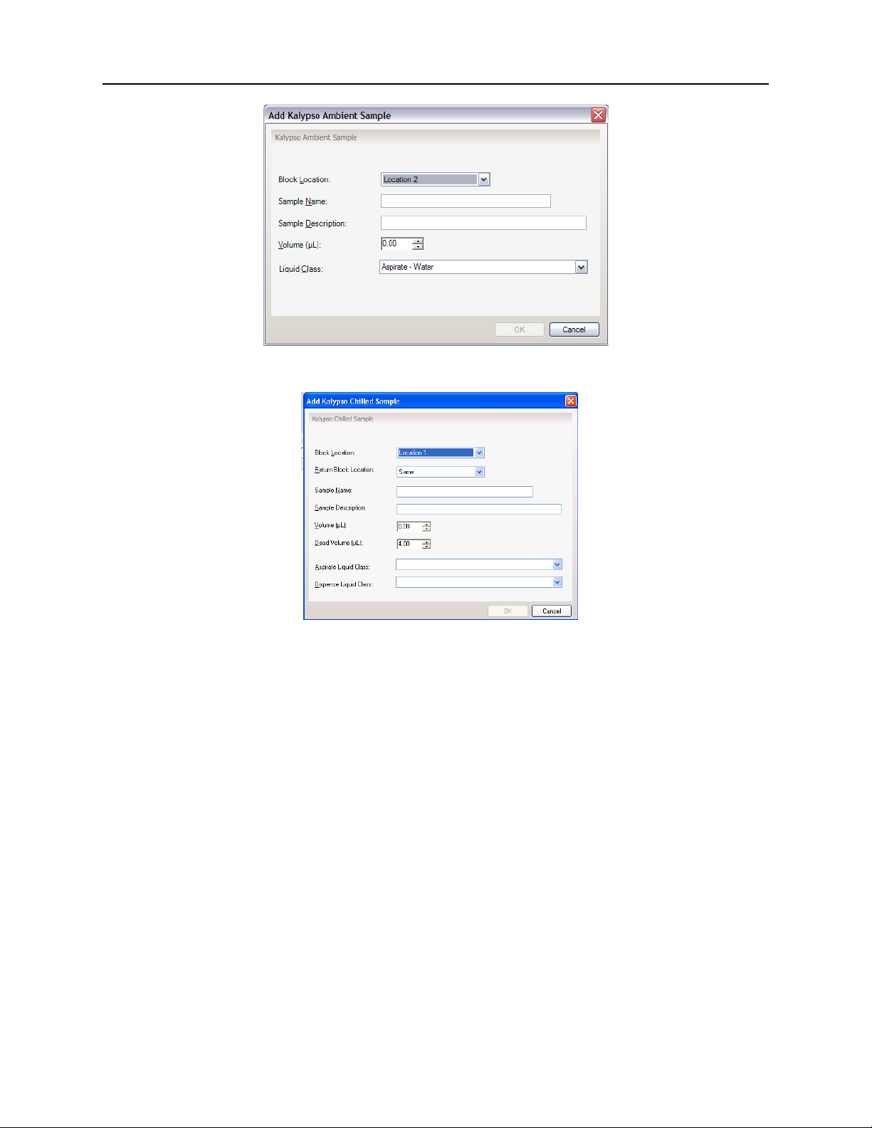
Add: Opens the Add Sample dialog to manually add a sample to the Chilled Block or Ambient
Block.
© 2007–2012 Rigaku Automation, Inc. 24 401718 Rev A
Page 31
Phoenix HT User Manual
Figure 14. Add Ambient Sample Dialog
Figure 15. Add Chilled Sample Dialog
Edit: Opens the Edit Sample dialog to edit a sample in the Chilled Block or Ambient Block. The
dialog contains the same controls and text boxes as the Add Sample dialog.
Remove: Removes the selected samples.
Clear All: Removes all samples in the list.
4.9.2 Onboard Plates Tab
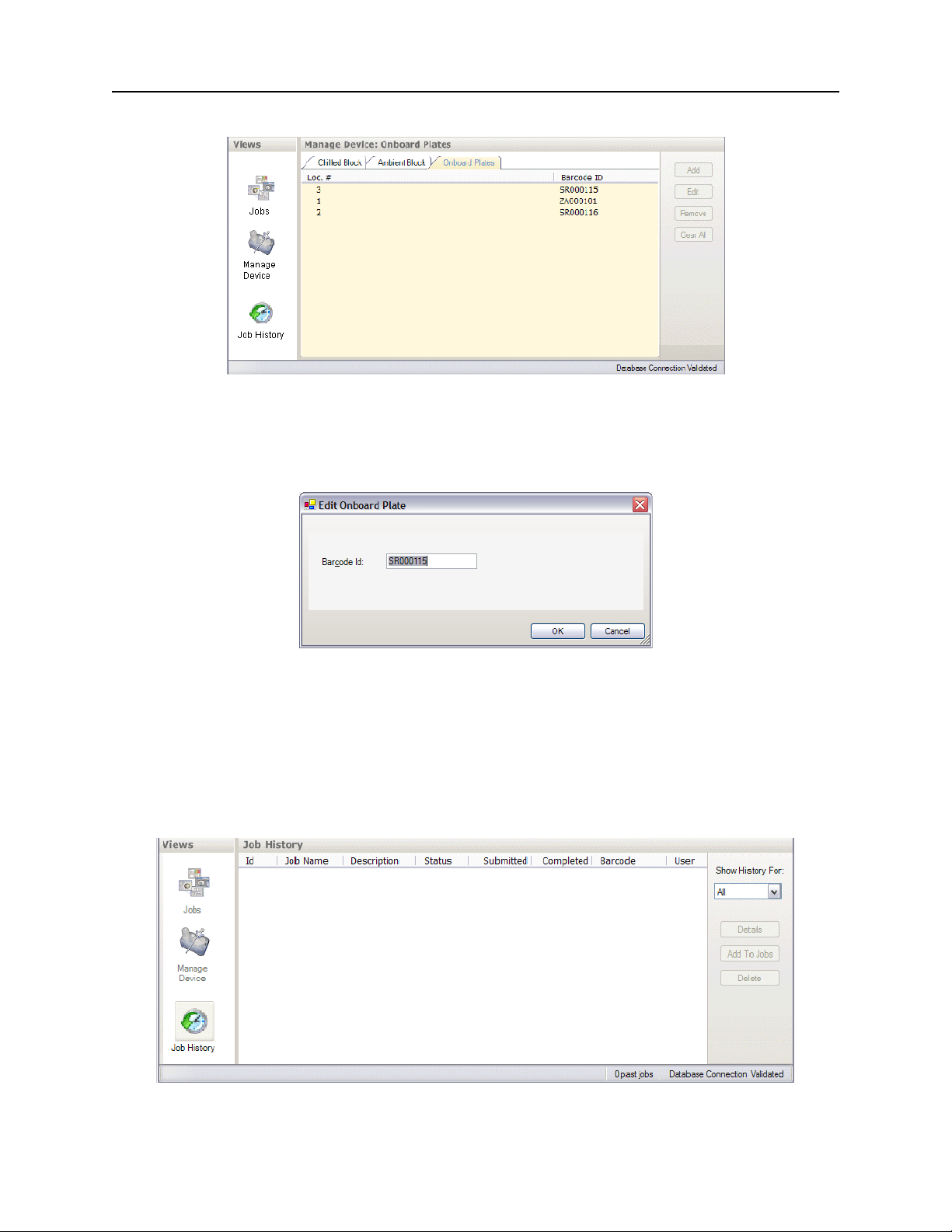
The Onboard Plates tab displays the plates currently on the shelves in the Phoenix HT base system.
Barcodes that start with Z identify source blocks. The CrystalMation system loads up to two
crystallization plates.
© 2007–2012 Rigaku Automation, Inc. 25 401718 Rev A
Page 32
Phoenix HT User Manual
Figure 16. Manage Devices View, Onboard Plates Tab
The active buttons on the right are:
Edit: Opens the Edit Onboard Plate dialog, which allows you to edit the plate barcode.
Remove: Removes the selected plates.
Clear All: Removes all plates in the list.
4.10. Job History View
The Job History view displays the jobs that have been completed.
Figure 17. Edit Onboard Plate Dialog
Figure 18. Job History View
© 2007–2012 Rigaku Automation, Inc. 26 401718 Rev A
Page 33

Phoenix HT User Manual
The menu and buttons on the right are:
Show History For: Opens a menu for the time period of the jobs listed.
Details: Opens a Details pane to show details of the selected job.
Add to Jobs: Opens a dialog to add a job to the list.
Delete: Removes the selected plates.
© 2007–2012 Rigaku Automation, Inc. 27 401718 Rev A
Page 34

CHAPTER 5. MAINTENANCE
This chapter contains the recommended preventive maintenance schedule and corrective
maintenance for the Phoenix HT instrument.
Topics covered are:
“Scheduled Maintenance” on page 28
“Equipment Cleaning” on page 28
“Daily Detergent Wash Required” on page 28
“Replacing the Nano-Tip Valve Harness Assembly” on page 30
“Calibrating the Nano Dispenser” on page 35
“Aligning the Nano Dispenser” on page 37
5.1. Scheduled Maintenance
Scheduled maintenance for the Phoenix HT consists of:
Perform a wash of the 96-syringe head and the nano head at the start and the end of each shift.
Clean the exterior nonworking surfaces of the Phoenix HT instrument once per year.
Perform professional preventive maintenance for the 96-syringe Phoenix head once a year.
This extensive process is an option in Rigaku Service Contracts.
5.2. Equipment Cleaning
Use a gentle nonabrasive detergent to clean surfaces of the Phoenix HT instrument. If a spill
occurs on the equipment, stop the current exterior process and immediately remove all foreign
matter.
CAUTION:
surface. Spray or apply cleaning fluid to a sponge or cloth, and apply the sponge or
cloth to the surface to be cleaned. Turn off the power and disconnect the power cord
prior to cleaning.
Do not spray cleaning fluid directly onto the Phoenix HT instrument
5.3. Daily Detergent Wash Required
Detergent wash is required daily to ensure proper functioning of the instrument. However, it is
optional as an integrated part of a protocol.
The detergent wash is a cleaning procedure for the nano dispenser needle and typically adds two
more minutes to the cycle time.
To perform a detergent wash:
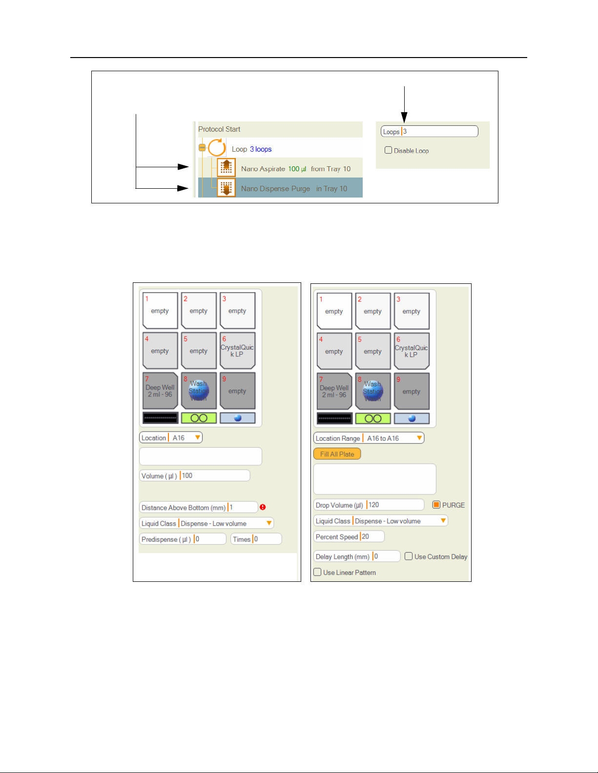
1. Drag a Loop icon into the method editor window. To nest items within the loop, drag the icon
to be nested to the Loop step.
2. Drag a Nano Aspirate and then a Nano Dispense icon to the Loop step.
© 2007–2012 Rigaku Automation, Inc. 28 401718 Rev A
Page 35
Phoenix HT User Manual
(1) Set the number of times to loop through the steps.
(2) Set the aspirate and dispense from the detergent cleaner in
the chiller block Tray 10.
Figure 1. Cleaning: Aspirate and Dispense Detergent Three Times
The aspirate and dispense steps (the detergent wash) can be configured in this manner. Note
the larger dispense volume with the purge selected. Because this is a wash, the aspirate and
dispense occur in the same location.
Figure 2. Configuring the Cleaning Steps
© 2007–2012 Rigaku Automation, Inc. 29 401718 Rev A
Page 36
Phoenix HT User Manual
5.4. Replacing the Nano-Tip Valve Harness Assembly
Replace the nano-tip if it starts to drip or becomes clogged or damaged.
5.4.1 Removing the Nano-Tip Valve Harness
1. Shut down all Phoenix components:
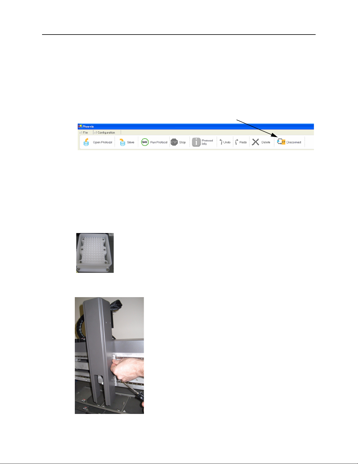
1Click the Disconnect button on the Phoenix toolbar to disconnect the motors. The button
label changes to Connect.
Disconnect button
Figure 3. Disconnect Button to start the Nano-Tip Replacement
2 Turn off the rocker switch on the nano dispenser controller box.
3 Turn off the power to the Phoenix instrument at the rocker switch on the back of the main
unit on the right hand side.
2. Gently push the nano dispenser head along the horizontal axis towards the center of the
Phoenix system in order to access the dispenser head cover easily.
3. Cover the white 96-channel wash station with a stiff paper or plastic covering temporarily so
that screws do not accidently slip into the drain holes during the next step.
4. Remove the cover from the nano dispenser head by removing the four screws on each side of
the cover with a Phillips head screwdriver.
© 2007–2012 Rigaku Automation, Inc. 30 401718 Rev A
Page 37
Phoenix HT User Manual
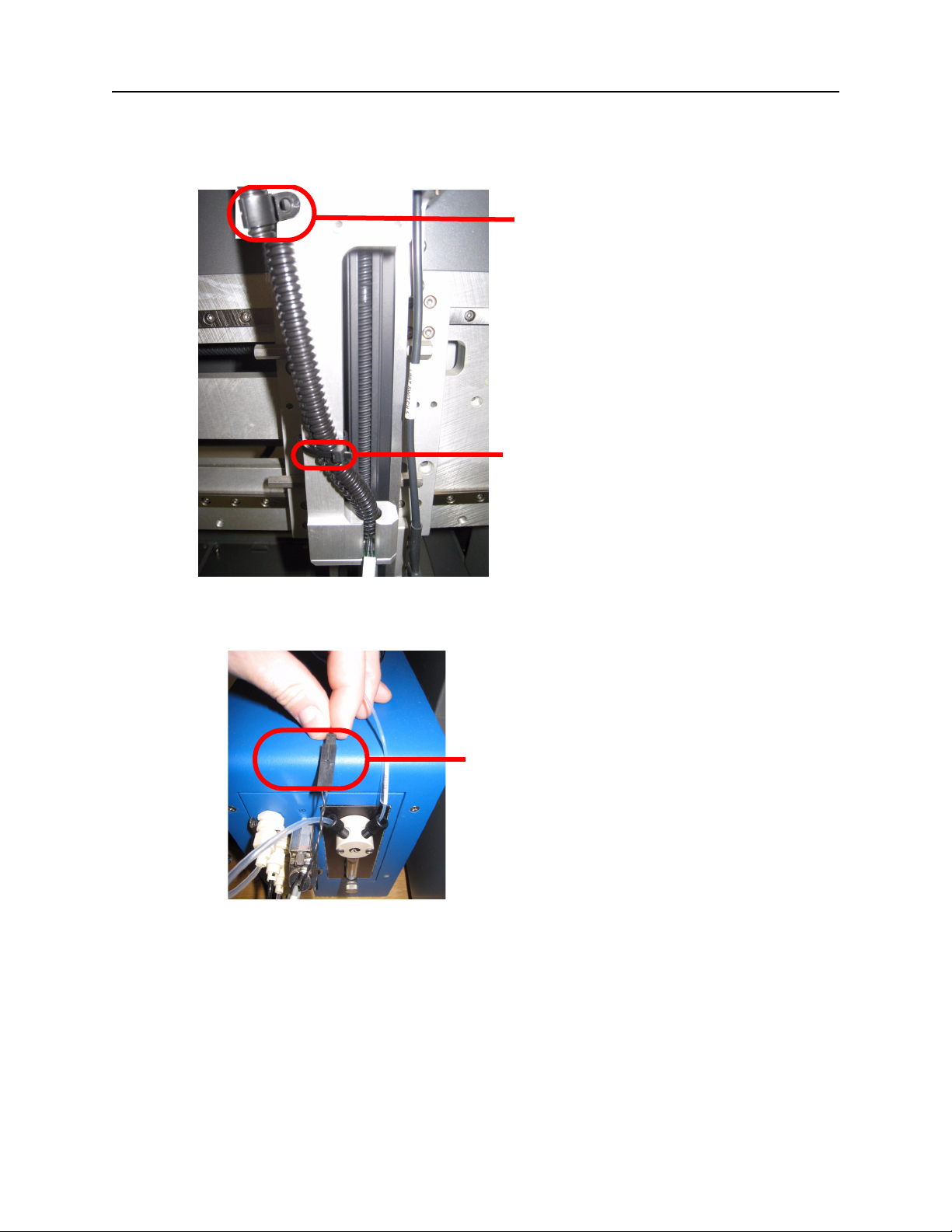
5. Remove the velcro strap (if present) and the P-clamp that holds the harness in place on the
nano head.
6. Remove the P-clamp on the back of the Phoenix system that also holds the harness in place.
Unscrew and remove P-clamp holding the
harness on the nano head.
Also unscrew and remove the P-clamp on the
back of the Phoenix system which holds the
harness in place.
Remove velcro strap.
7. Disconnect the nano dispenser from the nano dispense controller:
1 Unsnap and disconnect the black electrical wiring from the nano dispense controller.
Separate the black electrical connector, into two
parts.
© 2007–2012 Rigaku Automation, Inc. 31 401718 Rev A
Page 38
Phoenix HT User Manual
2 Twist and disconnect the pneumatic tubing from the nano dispense controller.
Twist and disconnect the
pneumatic tubing.
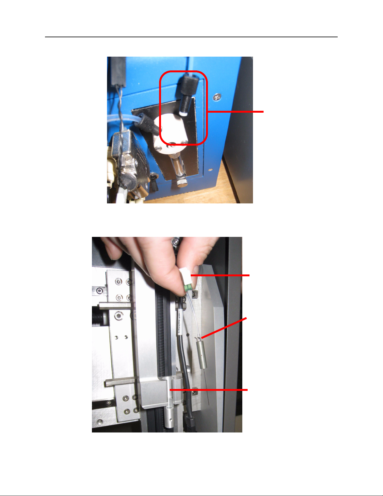
8. Carefully disconnect the nanotrigger wire from the needle tip by pulling on the white
connector which also holds the nano-tip in place and remove the nano-tip from the nano-tip
sleeve.
Nano trigger wire clip
Nano-tip assembly
Nano-tip sleeve
9. Remove the entire nano valve harness.
© 2007–2012 Rigaku Automation, Inc. 32 401718 Rev A
Page 39
Phoenix HT User Manual
5.4.2 Installing the Replacement Nano Valve Harness
Replacing the nano valve harness includes installing the new harness and updating the software
calibration file.
1. To install the new nano valve harness:
1 Connect the new pneumatic tubing to nano dispenser controller.
2 Insert the new black wiring connector into the nano dispenser controller.
3 Reinstall the P-clamp at the back of the Phoenix system and position the harness in it.
4 Thread the harness between the two cable guide pins on the nano head.
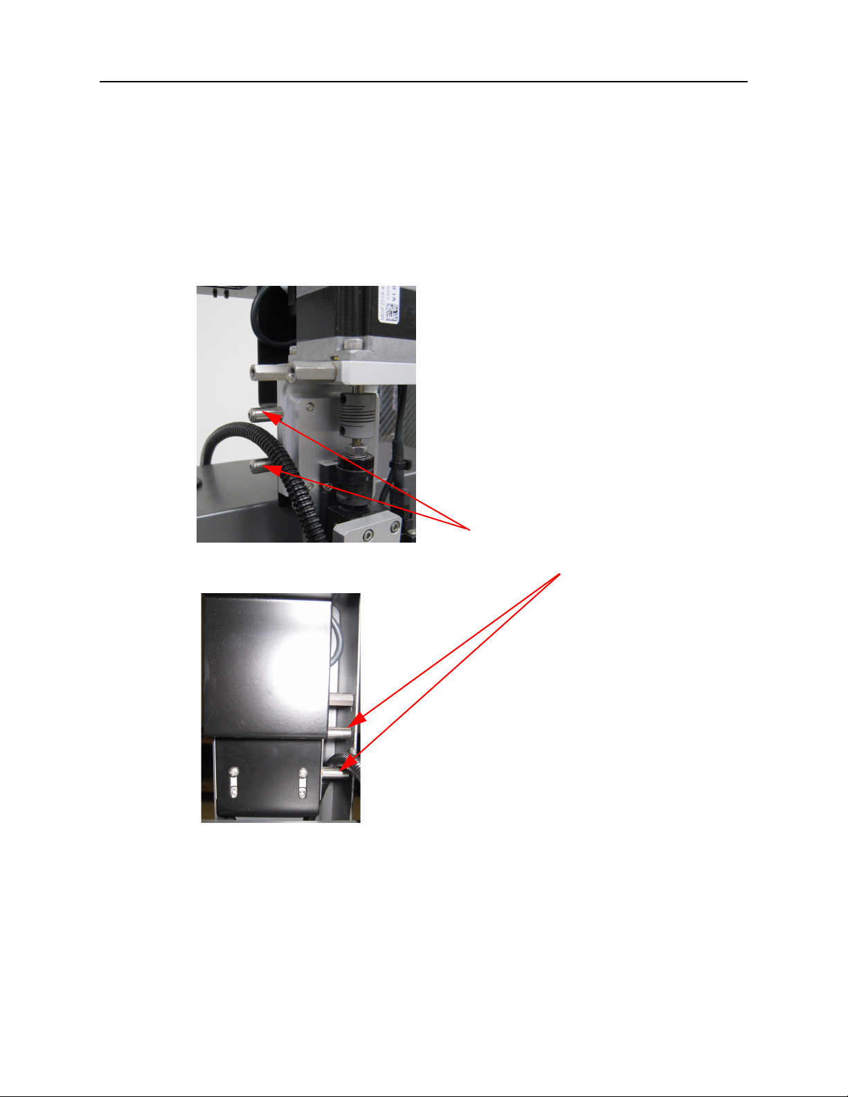
Front view of Phoenix nano dispenser head
Rear view of the Phoenix nano dispenser head
Position the harness between the two cable
guide pins on the nano dispenser head
5 Reinstall the second P-clamp onto the front of the nano dispenser head and position the
harness in it with the appropriate amount of slack to allow movement horizontally to the
far left and far right of the Phoenix instrument and vertically down to the bottom of the
wash station.
6 Uncap the nano-tip and slide the nano-tip assembly into the nano head sleeve.
7 Gently insert the white nanotrigger wire clip onto the nano-tip assembly.
© 2007–2012 Rigaku Automation, Inc. 33 401718 Rev A
Page 40

Phoenix HT User Manual
8 Reinstall the velcro strap around the nano head and harness.
9 Using the Phillips head screwdriver and eight screws previously removed, re-attach the
nano head cover onto the Phoenix nano dispenser.
2. Note the serial number on the label of the nano dispenser pneumatic tube near the controller
box (also printed on the replacement nano dispenser package).
3. Update the software calibration file to recognize the new nano valve harness assembly.
1 Check that the Phoenix software is shut down.
2 Go to the following directory :
..\Phoenix\RobbinsNanoCalibration\RobbinsNanoHardwareCalibration\
3 Change the prefix of the removed Valve Harness Assembly Hardware Calibration file (if
one exists) to "CHxx...".
For example "CH01-H0001.xml" would change to "CHxx-H0001.xml". This will deactivate
the removed Valve Assembly’s Hardware Calibration.
4 Select the Hardware Calibration file for the new Valve Assembly either in the same
directory, a sub directory, or sent with new the new Valve Assembly.
Change the prefix to start with the channel it was placed into. For example if harness
H0002 is placed into channel 1, change "CHxx-H0002.xml" to "CH01-H0002.xml.
Make sure the new harness’s Hardware Calibration file is located in the same location at:
...\Phoenix\RobbinsNanoCalibration\RobbinsNanoHardwareCalibration\
While CHXX such as CH01, CH02, etc. must be the first four characters of the file name,
for the calibration file to be recognized, the naming convention of any other information
in the file name is arbitrary.
5 Restart the Phoenix software.
6 Look at the log file: "...\Phoenix\Logs\Phoenix.log" to see that the correct Hardware
Calibration file has been associated with the correct channel.
Search for the words "hardware calibration" starting from the bottom of the file to find the
correct line.
The name of the XML file should be seen as in this example:
CH01 is using hardware calibration file: CHxx_H00xx.xml Date.
This completes the Nano Valve Harness Assembly Exchange and Hardware Calibration.
Note: The Excel file for each Nano harness is the final measurement of performance at
ARI. The associated CHXX .XML file is the file, read by the software, that results in those
measurements.
4. Check that all connections and tubing is tight.
5. Turn on the power for the nano controller box and the Phoenix HT instrument. Re-establish
the software connection with the instrument by selecting Connect on the Phoenix software.
6. Do a protocol test run to confirm that all parts are full operational.
© 2007–2012 Rigaku Automation, Inc. 34 401718 Rev A
Page 41
Phoenix HT User Manual
7. Observe that the vacuum pump runs for a short time, then stops.
If it runs continuously, remove and reinstall the new tip.
If the vacuum pump is working properly, obtain one sample tube filled with water and
gently submerge the nano-tip in it. If the tip bubbles the liquid, replace the nano-tip before
going further.
8. Calibrate the nano-tip for all nano-accessible tray positions.
1Select Disconnect to disconnect the instrument.
2 Remove any obstacles or consumables on the tray positions.
3 Ensure that the predrilled holes for the accessible tray positions are completely visible.
Using a flashlight is highly recommended.
9. If the previous nano-tip was well-aligned, proceed to “Aligning the Nano Dispenser” on
page 37 to ensure that the new nano-tip is properly configured.
If the previous nano-tip was not well aligned or the alignment is uncertain, proceed to
“Calibrating the Nano Dispenser” on page 35, then complete the process with “Aligning the
Nano Dispenser” on page 37.
5.5. Calibrating the Nano Dispenser
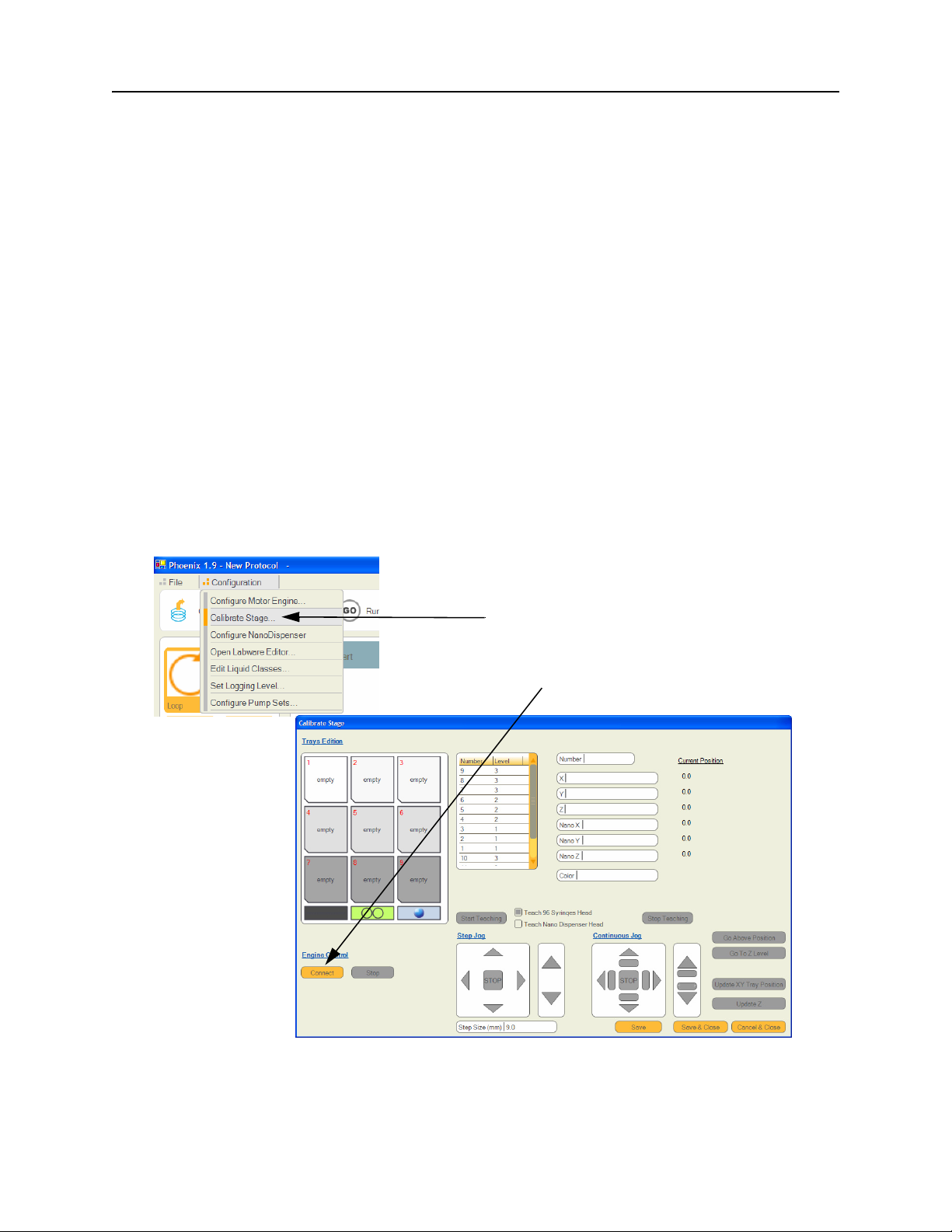
1. In the ARI Phoenix application, select Calibrate Stage in the Configuration menu.
Calibrate Stage selection
Connect button
Figure 4. Calibrate Stage Step
© 2007–2012 Rigaku Automation, Inc. 35 401718 Rev A
Page 42
Phoenix HT User Manual
2. Click the Connect button in the Engine Control section. The dialogue appears as the instrument
homes all motors.
Always WAIT until the instrument has fully completed a requested command and the
software correctly displays the outcome.
IMPORTANT: Do not use Go to Z Level or any of the movement vectors under Continuous
Jog. These commands could cause a crash.
3. Select from the list a Nano-accessible position. Do not select the tray positions with the words
‘empty’ in them. Please select from the list that also displays the level.
4. When highlighted, click the Teach Nano Dispenser Head button.
5. Click the Start Teaching button.
6. Click the Go Above Position button. The Nano head hovers over the selected tray position.
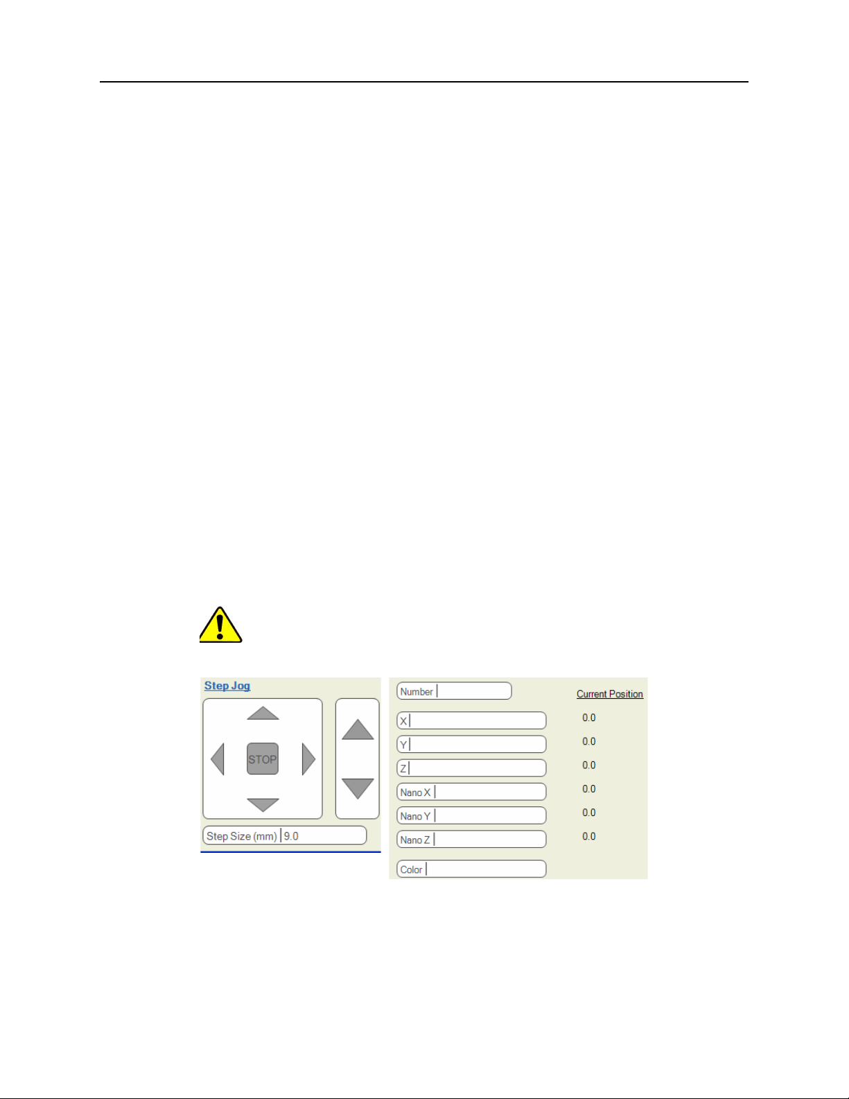
7. Under Step Jog, notice the Step Size (mm) display. As you click an arrow to select a movement
axis, the instrument moves the amount displayed. The instrument also displays the saved
location and the current nano-tip location.
The rectangular box with four arrows and the stop in the middle moves the nano-tip left
and right (left and right arrows) and moves the stage forward and back (down and up
arrows).
The rectangular box with two arrows controls the nano-tip up and down movement.
Cautiously lower the nano-tip toward the tray in order to accurately center the tip above the
predrilled target (or the center of the wash station, for instance).
Make sure the software has the opportunity to display the current position before attempting
to move again.
As the nano-tip approaches the top of the target, click the arrow to the right of the number to
select a smaller mm value and decrease the step size.
CAUTION Do not make contact with the tray. Doing so could damage and bend
the tip.
Figure 5. Step Jog Display
8. Using the other directional arrows, align the tip so that is perfectly centered over the target.
Keep in mind that the nano-tip is incapable of moving backward or forward; the stage is what
moves. So, if the nano-tip is in front of the target, move the stage forward (down arrow) to
meet the tip.
© 2007–2012 Rigaku Automation, Inc. 36 401718 Rev A
Page 43

Phoenix HT User Manual
9. When centered, click the Update XY Tray Position. button
10. Click the Save button.
11. Click the Stop Teaching button.
12. Click the Save and Close button.
13. Repeat steps 13 through 24 for the remaining tray positions.
Notes
Aligning the nano-tip to these targets should be considered a guideline. Ultimately, you may find
that further tweaking is required after running test plates. If this is the case, perform steps 11
through 17, then 20 through 23, making adjustments to the XY. There is no need to move the nanotip down toward the target.
To extend the life of the nano-tip, program ample water immediately after protein dispensing. For
extra cleaning, you may wish to incorporate detergent washes.
We recommended filtering and spinning down proteins before use to remove precipitate from
solutions that can clog the nano-tip.
Always ensure the appropriate consumable is placed and secured on the deck, and that all
reagents are filled. Ensure that plates are in correct orientation with the A1 well in the front left
position.
5.6. Aligning the Nano Dispenser
The Art Robbins’ alignment procedure positions the heads on the registration spot on the deck
and uses the Delay (mm) parameters in the nanodispense command to shift the drop until the two
coincide.
The below procedure provides additional precision. When the nanodispenser tip on the Phoenix is
changed, its dispense position will shift, even when removing and replacing the same tip. In order
to ensure drop on drop dispensing, its dispense position must be adjusted so that it coincides with
the dispense position of the 96-syringe head.
Follow the procedure below to align the nanodispense position.
1. Back up all of your settings. This will save a lot of time if you make a mistake and need to
revert to the original settings
The easiest way to do this is to a navigate in Windows Explorer to C:\Program Files, right-
click on the Phoenix directory, and select Send to: Compressed (zip) folder.
2. Start the ARI Phoenix software and connect to the instrument to home the axes
3. Dispense a test plate using the protocol FAT Dispense 100nl+ 100nl on Lucite Plate.pro and note
in which direction and estimate the distance the protein drop must move in both X and Y. This
value will usually be less than 1 mm in each direction.
4. Re-teach the nanodispenser position:
1 Disconnect, then select Configuration > Calibrate Stage window in the ARI Phoenix
software.
2 Connect to the instrument again to home the motors, then select the position in which you
are dispensing your plate. This is usually position 1.
3Select Teach Nanodispenser Head.
4Click the “Go above XY position” to send the nanodispenser above its current taught plate
position.
© 2007–2012 Rigaku Automation, Inc. 37 401718 Rev A
Page 44

Phoenix HT User Manual
5 Adjust the jog increment to the desired resolution using the pulldown box at the bottom
of the page, then jog the X and Y axes the distance estimated in step 3.
Keep in mind that the shelves will need to move in the opposite direction.
6Click Set Taught Position, then Stop Teaching then Save and Close.
5. Test dispensing:
1 Reconnect to the instrument and create another test plate.
2 If the drops are still not merging, determine the distance you need to move the
nanodispenser tip, and then repeat the substeps under step 4.
3 Ensure that you keep track of the net distance you have moved from your original starting
position because you will need to apply this to the rest of the dispense positions.
6. Apply offsets to all positions:
1 Once you are satisfied with the drop placement on one position, the position shift must be
applied to all of the other nanodispense positions.
2 Open the calibrate stage view, connect, and then select the nanodispenser in position 2.
3Click Go above XY position and then jog the axes by the net distance you determined for the
first plate position.
4Click Set Taught Position, then Stop Teaching, then Save to save the adjustments made.
5 Repeat substeps 1 through 3 under step 6 for all positions into which the nanodispenser
can dispense (Positions 1-6).
6 Once you have made all the necessary dispense adjustments, click Save and Close to exit
the calibrate page.
7. Run a test plate on each of the positions using FAT Dispense 100nl+ 100nl on Lucite Plate.pro to
ensure that you are satisfied with the drop placement.
© 2007–2012 Rigaku Automation, Inc. 38 401718 Rev A
Page 45

APPENDIX A. OPTIONS AND SPARE PARTS
The following options and spare parts list is current as of the date of publication. Contact the
Rigaku Automation Service organization for updated information.
Table 3. Phoenix Options and Spare Parts
Part # Description
205681 Spare Phoenix DT 96-channel syringe head
101716 Phoenix HT option
Includes enclosure with free standing cabinetry options.
Active Nesting™ with plate sensors for accurate plate placement
Anti-static curtain
205674 100µl flex needle syringe
Average replacement cycle: 4 syringes per year
(4 spare syringes and needles provided with Phoenix DT)
205673 100µl Teflon Tips – Quantity 100
Average replacement cycle: 100 tips per year
206796 One (1) New ARI Nano Nozzle
Average replacement cycle: 3 nozzles per year
(1 spare Nano Nozzle provided with Phoenix DT)
206576 CrystalMation Intelli-plate – non barcoded – 500/Case (not used with UV)
Low-Profile
288-well with 96 reservoirs in standard SBS format
1µl well volume and 100µl reservoir volume
206577 CrystalMation Intelli-plate – prebarcoded – 500/Case (not used with UV)
Low-Profile
288-well with 96 reservoirs in standard SBS format
1µl well volume and 100µl reservoir volume
Rigaku standard barcode format only
© 2007–2012 Rigaku Automation, Inc. 39 401718 Rev A
Page 46
APPENDIX B. FACILITIES LAYOUT AND CABLING
The following sections display physical and electrical layout considerations for the Phoenix HT.
B.1. Mechanical Layout
The following information is current as of the date of publication. Contact the Rigaku Automation
Service organization for updated information.
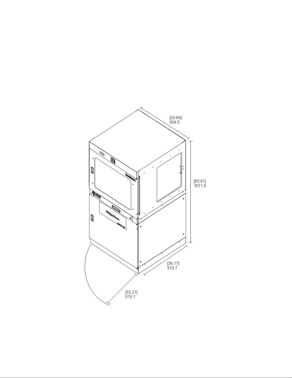
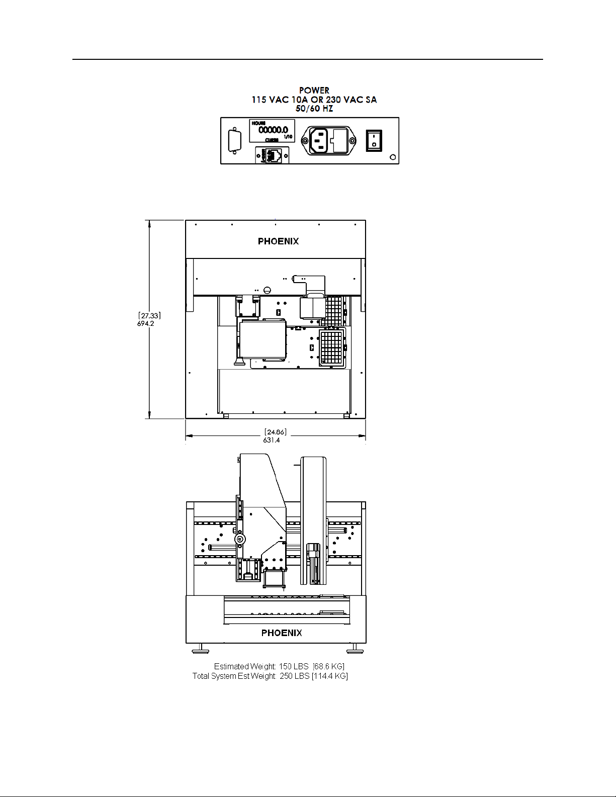
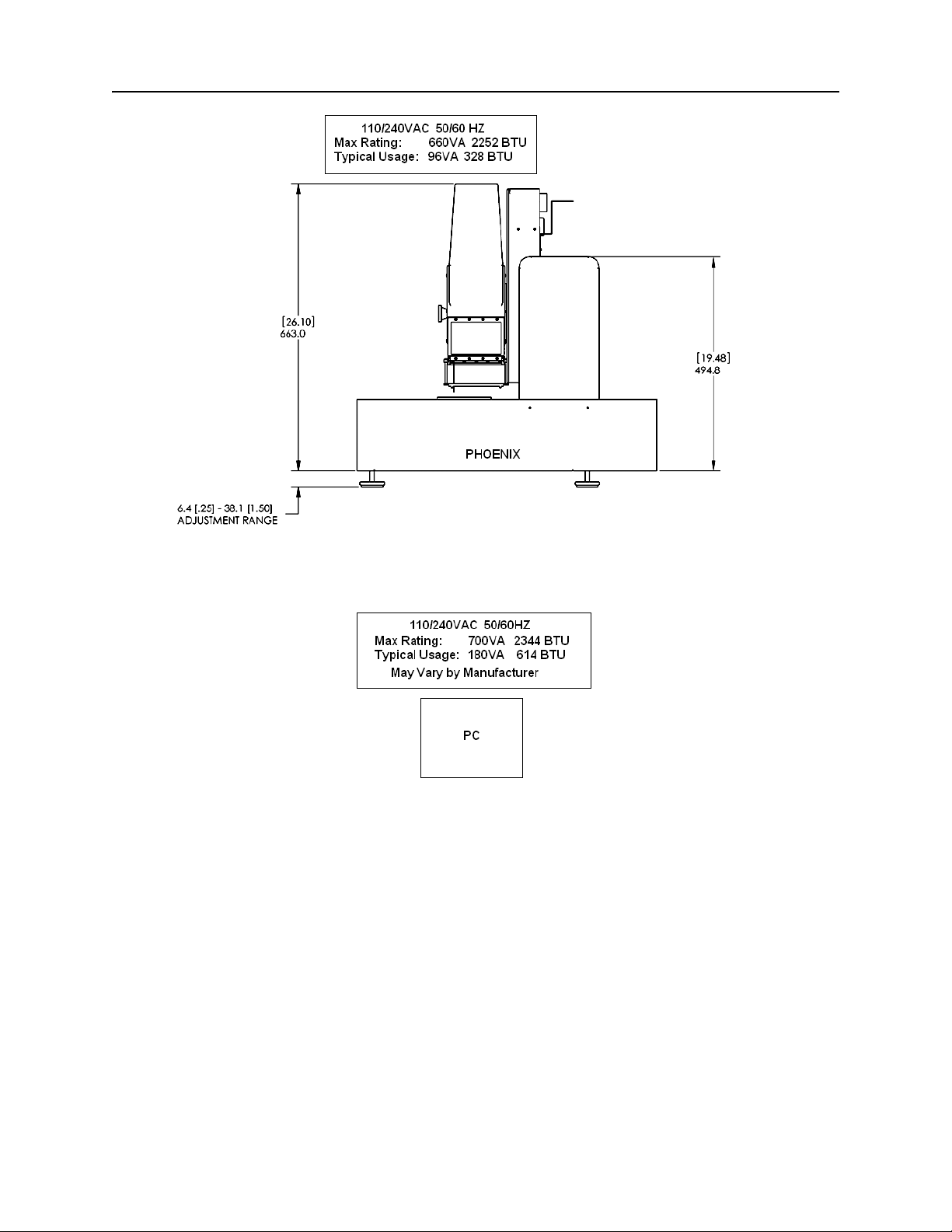
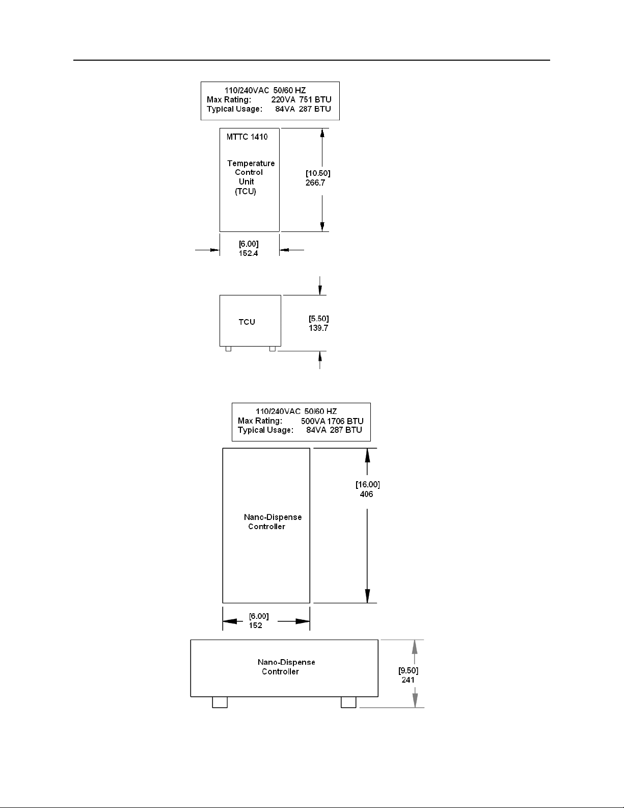
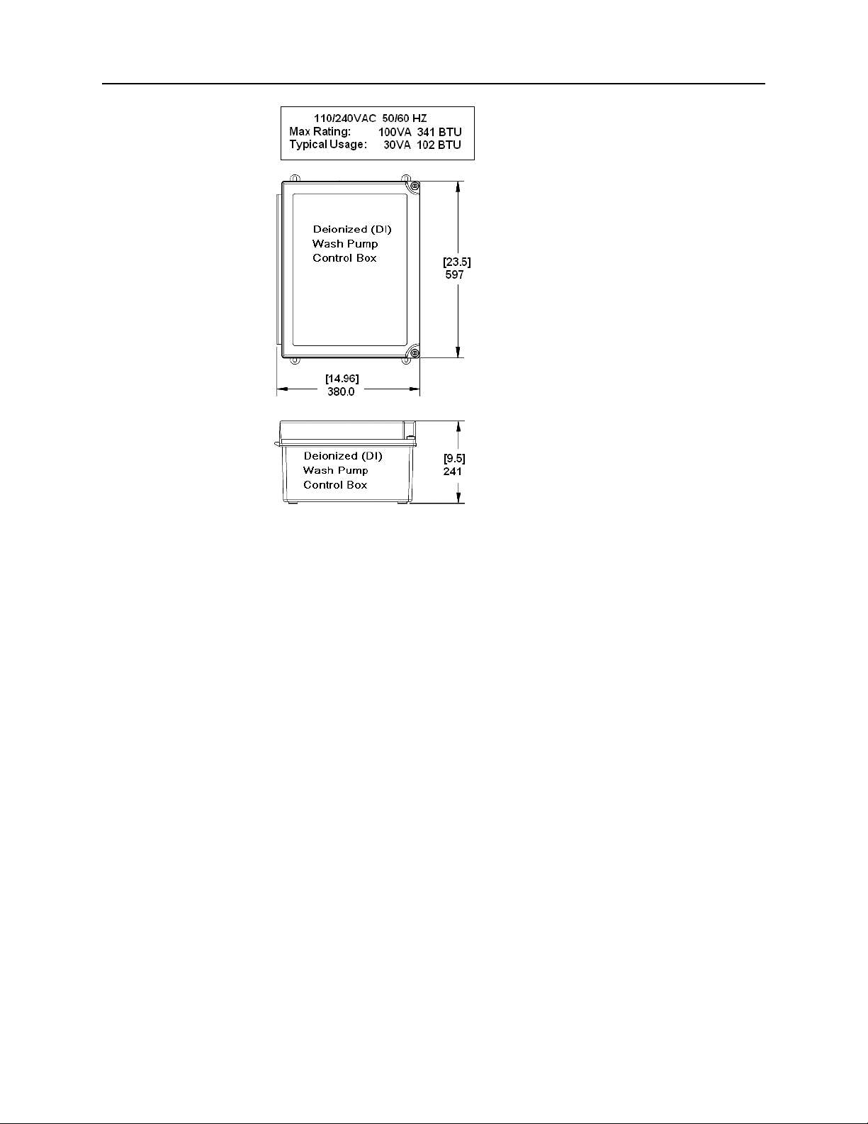
Bracketed dimensions are in inches. Unbracketed dimensions are in millimeters.
Figure 44. Phoenix HT Enclosure
© 2007–2012 Rigaku Automation, Inc. 40 401718 Rev A
Page 47
Phoenix HT User Manual
Figure 45. Power and Network Connections
The following figures are components installed in the Phoenix HT enclosure.
Top View
Front View
Figure 46. Phoenix Base System Front and Top Dimensions and Weight
© 2007–2012 Rigaku Automation, Inc. 41 401718 Rev A
Page 48
Phoenix HT User Manual
Figure 47. Phoenix Side (Depth) Dimensions and Power Requirements
Figure 48. PC Power Requirements
© 2007–2012 Rigaku Automation, Inc. 42 401718 Rev A
Page 49
Phoenix HT User Manual
Top View
Side View
Figure 49. Temperature Controller Unit Dimensions and Power Requirements
Top View
Side View
Figure 50. Nano-Dispense Controller Dimensions and Power Requirements
© 2007–2012 Rigaku Automation, Inc. 43 401718 Rev A
Page 50
Phoenix HT User Manual
Top View
Side View
Figure 51. Water Pump Control Box, Dimensions and Power Requirements
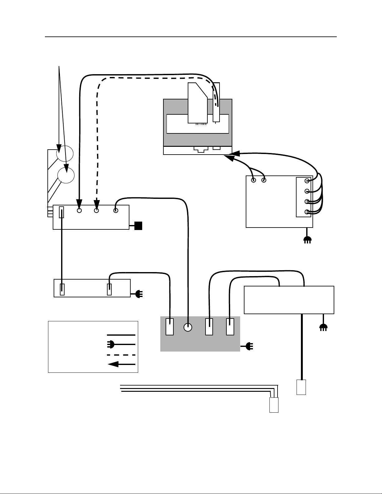
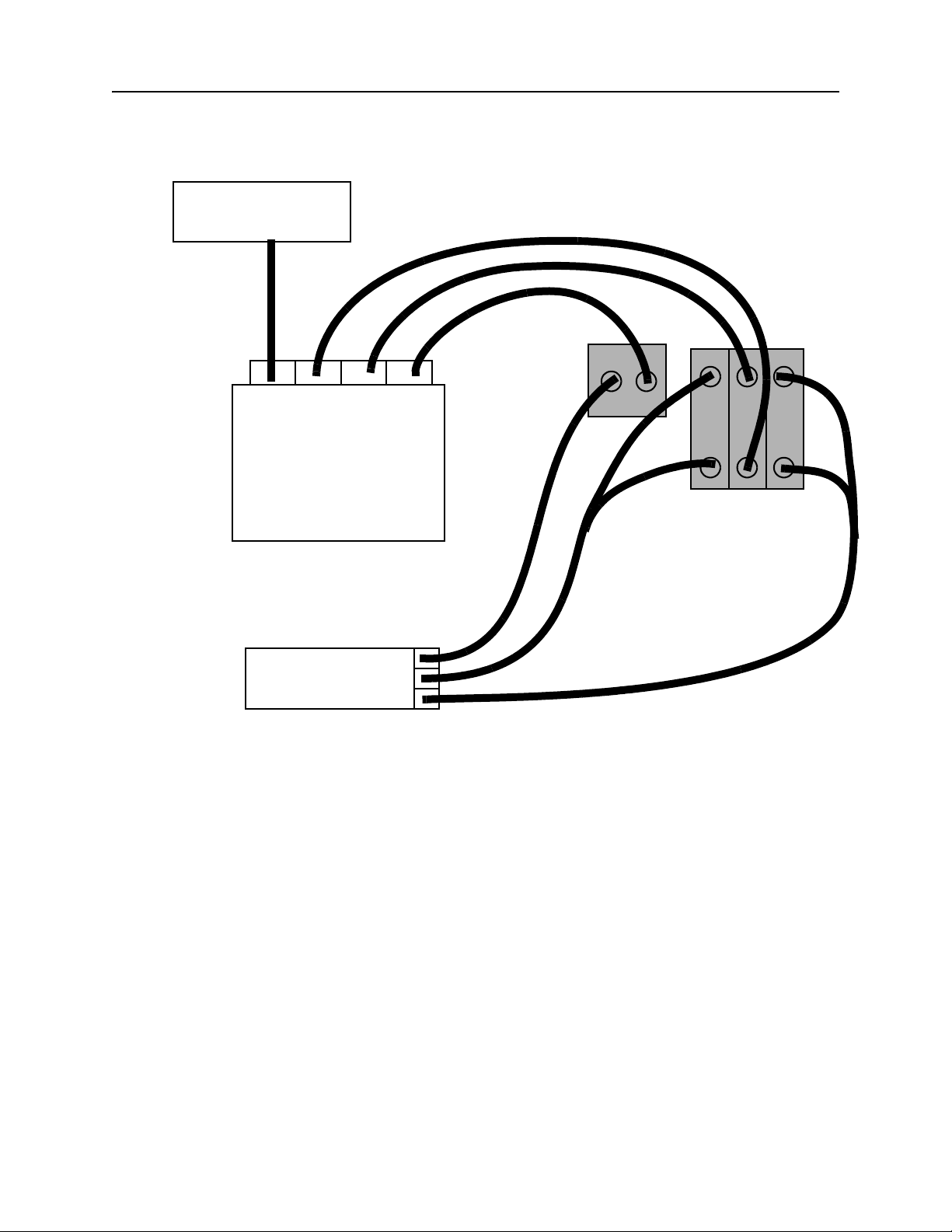
B.2. System Cabling
The following connections must be taken to properly set up the system. This does not need to be
repeated unless the equipment has been disconnected.
Connect the cables to the Facilities Panels of the Phoenix HT base system, the temperature control,
the pneumatic control, the control computer, and the wash system as shown.
© 2007–2012 Rigaku Automation, Inc. 44 401718 Rev A
Page 51
Nanotip Wash
Reservoir Bottles
Phoenix HT User Manual
Black Line Tip Trigger
Clear Supply Line
to Nanotip
(wire)
Trigger
Nano-Dispense
Controller
(Water supply and
waste water
connections on
underside)
Nano
DC Power
connected to
Adapter
Phoenix
Base System
(Electrical
connections on
rear panel)
To
sensor
Sensor
Temperature
Control Unit
To protein
chiller block
TEC
FAN
+
-
+
-
AC
Power
blk
red
grn
wht
brn
blu
USB
Control Computer
(actual computer may vary)
LEGEND:
Signal cable
AC power cable
Pneumatic line
Do not disconnect
at arrow
USB
AC
Power
RS-
422
Trigger
Nano
Wash
Head
Wash
Water Pump Control Box
AC
Power
Phoenix
electrical connections
(rear panel of base system)
Waste-water lines connected to underside of Phoenix
Waste-Water Tank
AC
Power
Or
plumbed
to house
water
Supply Tank
Figure 52. Phoenix HT Electrical Cable Connections
© 2007–2012 Rigaku Automation, Inc. 45 401718 Rev A
Page 52
Water supply
(Plumbed)
Supply
Phoenix HT User Manual
Nano wash
Head wash rear
Water Control Module
Waste water
(Plumbed)
Head wash front
Figure 53. Phoenix HT Water Connections
Phoenix
water connections
(underside of base system)
© 2007–2012 Rigaku Automation, Inc. 46 401718 Rev A
Page 53
Phoenix HT User Manual
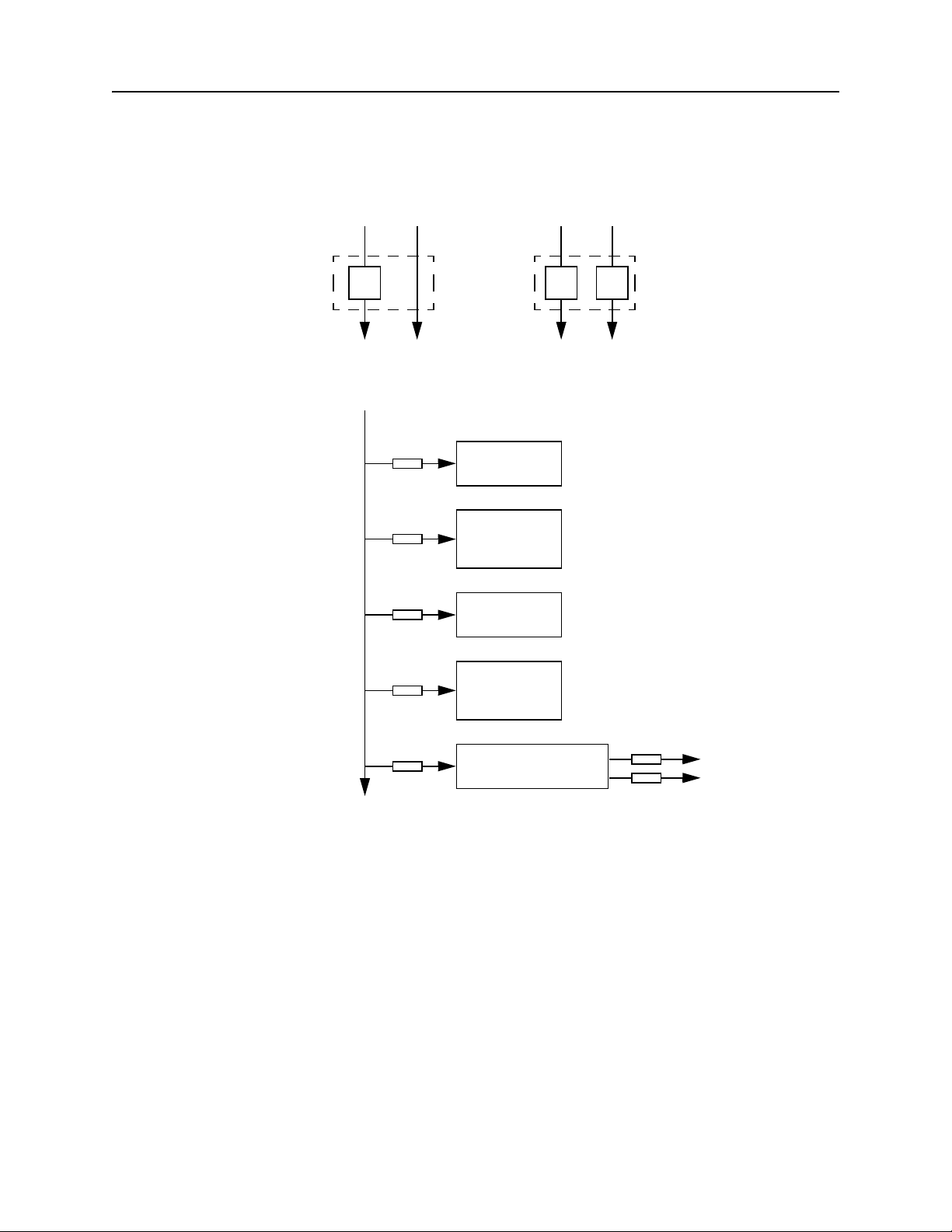
The CrystalMation Phoenix HT enclosure contains
the following additional 250-volt, slow-acting
fuses.
120 V 240 V
Line Neutral
Line Neutral
FU-1 FU-1
8 A
AC Line
FU-2
3.15 A
FU-3
2 A
FU-4
2 A
FU-5
0.5 A
FU-6
1.6 A
Phoenix
base system
Nano-
Dispense
Controller
Peltier Chill
Block
Anti-Static
Bar Power
Supply
DC Power
Supply
8 A 8 A
FU-7
1.6 A
24 V
5 V
FU-8
3.15 A
Figure 54. Phoenix HT Enclosure Power and Fuse Specifications
© 2007–2012 Rigaku Automation, Inc. 47 401718 Rev A
Page 54

APPENDIX C. REVISION HISTORY
Document: Phoenix HT User Manual
Part Number: 401718 Rev A
Effective Date Revision Description of change
05/30/12 A Complete rework of and update to Phoenix RE user manual DOO1457
published in 2008, separated into Phoenix HT User Manual and
Phoenix DT Supplement manual.
APPROVAL BLOCK
TITLE NAME SIGNATURE DATE
Director, Scientific
Applications
Director, Software
Engineering
Sr Director, Automation
Services
Jian Xu
Max Petersen
Chris Rossman
© 2007–2012 Rigaku Automation, Inc. 48 401718 Rev A
Page 55

Index
A
active nest
active nest terminals 8
active nest toggle 22
Add New Job 20
adding chilled sample 16
Allow Multi-Select for Jobs 21
anti-static bar 7
Auto-Run by Protein Order 21
Auto-Run checkbox 15, 18
C
cabling
checking liquid volumes 15
checking materials inventory 15
chiller block, slot locations 3
class of chemicals vi
cleaning equipment 28
D
defining batch load in CrystalTrak
defining plates in CrystalTrak 15
Delete Job 21
deleting a job or task 15
detergent wash 28
dimensions
drop design vi
E
Edit Job
error messages in red 17
F
File menu
Filter Job Display 21
H
hanging drop
hardware parts 39
hazards 9
Help menu 23
7
44
electrical 45
water connections 46
base system
base unit side 42
enclosure 40
nano-dispense controller 43
temp controller unit 43
water control module 44
41
20
20
vi
15
J
Job History view
Jobs menu 20
Jobs view 23
L
layout, mechanical
light indicators 12
Logging command 22
M
Machine Control
main window 19
maintenance
daily detergent wash
equipment cleaning 28
replacing the nano harness 30
scheduled 28
Manage Device > Ambient Block tab 24
Manage Device > Chilled Block tab 17, 24
Manage Device > Onboard Plates tab 25
Manage Device view 24
N
nano-dispense controller, parts of
nano-dispense needle, detergent wash 28
nano-dispenser
aligning the nano-dispenser
calibrating the nano-dispenser 35
nano-tip
installing the nano harness
removing the nano harness 30
replacing the nano harness assembly 30
O
oil experiment
Options menu
Database Name
Job Input/Output Paths 23
Purge jobs to history 23
Server Name 23
overview 1
P
part names
performing plate inventory 22
physical layout 40
plate definitions in CrystalTrak 15
plate inventory 22
plates, approved for Phoenix HT 14
Poll I/O Status 21
26
40
22
28
6
37
33
vi
23
vi
© 2007–2012 Rigaku Automation, Inc. 49 401718 Rev A
Page 56

Phoenix HT User Manual
Poll Phoenix Status 21
positioning plates 14
positioning sample tubes 14
power requirements 41
base unit and PC 42
nano-dispense controller 43
temp controller unit 43
water control module 44
power-on procedure 11
procedures
adding chilled sample
aligning the nano- dispenser 37
calibrating the nano-dispenser 35
checking liquid volumes 15
checking materials inventory 15
defining plates in CrystalTrak 15
initial setup 14
installing the nano harness 33
performing plate inventory 22
positioning plates 14
positioning sample tubes 14
power-on 11
registering protein samples 15
replacing the nano harness assembly 30
resetting the system after shutdown 13
running the jobs and tasks 18
running the system 12, 15
shutting down the system 12
product description 1
product options 2
protein chiller block
adjusting temperature
protein chiller block, slot locations 3
R
recipe
vi
Refresh DB Info 22
Refresh Jobs 21
Register Samples button 16
registering protein samples 15
reservoir design vi
Reset Dialog Sizing 22
resetting the system after shutdown 13
revision history 40, 48
Robot menu 22
running the Jobs and tasks 18
running the system 12, 15
16
4
sample protein vi
scope of this manual 1
sensor bar 8
sensors, plate and shelf 8
Service and Support 9
setup, initial 14
shutting down the system 12
sitting drop vi
spare parts 39
standard screen vi
status light indicators 3, 12
stock vi
stop, start, and emergency stop pushbuttons 13
T
temperature controller, power on/off
terminology vi
Toggle Hour Meter 23
Tools menu 21
troubleshooting 10
U
Use Automation checkbox
V
View Application Log command
View menu 20
Views pane 23
W
warnings
wash stations 5, 6
water pump control box 5
weight, base system 41
9
15
4
23
S
safety features
© 2007–2012 Rigaku Automation, Inc. 50 401718 Rev A
8
 Loading...