


Instruction and ser vice manual
Repair Instructions
Vacuum pumps
VWZ
VWZ 702
VWZ 1002
VWZ 1202
BE 134
1.4.99
Werner Rietschle
GmbH + Co. KG
Postfach 1260
D-79642 Schopfheim
07622/392-0
Fax 07622/392300
e-mail: info@rietschle.com
http://www.rietschle.com
Rietschle (UK) Ltd.
Bellingham Way
New Hythe
Kent ME20 6XS
01622 / 716816
Fax 01622/715115
e-mail: info@rietschle.co.uk
http://www.rietschle.co.uk

Contents Page
Instruction and service manual VWZ 102 – VWZ 402
1. Introduction 3
2. Application 3
3. Variations and Construction 3
3.1 Variations 3
3.2 Construction 4
3.3 Data sheets and spare parts lists 5
3.4 Accessories 5
3.5 Typical Field of Application 5
4. Method of Operation 6
4.1 Pump 6
4.2 Pressure Relief Valve 6
4.3 Oil Lubrication 6
4.4 Shaft Seals 6
5. Installation 6
5.1 Mechanical Installation 6
5.1.1 Mounting 6
5.1.2 Suction side 6
5.1.3 Exhaust 6
5.2 Electrical Installation 7
5.2.1 General 7
5.2.2 Approximate values for setting motor overload protection 7
5.2.3 Electrical connections for the motor and control equipment 7
5.2.4 Terminal Box Connections Closed Circuit Cooling 7
6. Normal Operation 8
6.1 Cooling Liquid 8
6.1.1 Fresh or External Cooling 8
6.1.2 Closed Circuit Cooling 8
6.1.3 Cooling Liquid Control 8
6.2 Oil Lubrication 8
6.3 Oil Metering Pump 8
6.4 Initial Operation 9
7. Maintenance 9
7.1 Oil Metering Pump 9
7.2 Oil Mist Separator 10
7.2.1 Maintenance of Oil Mist Separator 10
8. Trouble Shooting 10
8.1 Pump Overload 10
8.2 Drop off of Vacuum 10
8.3 High Oil Consumption 10
Repair Instructions VWZ 102 – VWZ 402
1. Removal and Reassembly of Water Jacket 11
2. Changing LP and HP Stages 11
2.1 Removal of Stages 11
2.2 Refitting of Stages 11
3. Removal and Reassembly of Drive 11
4. Changing Coupling Rubbers and Pins 12
4.1 Drive Motor 12
4.2 On Stages 12
5. Repairs to Stages, Non-Drive End (B) 12
5.1 Removal of Bearings and Seals 12
5.2 Reassembly of Bearings and Seals 13
6. Changing Blades 14
7. Repairs to Stages, Drive End (A) 14
7.1 Removal of Bearings and Seals 14
7.2 Reassembly of Bearings and Seals 15
8. Repairs to Gearbox 16
8.1 Removal and Reassembly of Gearbox 16
8.2 Changing Gear Wheels and Ball Bearings in Gearbox Housing 16
8.3 Changing Bearings, Shaft Seals and Seals 17
9. Other Repairs 17
9.1 Cleaning the Suction and Exhaust Parts in Connection Housing 17
9.2 Changing the Pressure Relief Valve 17
10. Instructions for Storing Oil Metering Rotary Vane Vacuum Pumps 17
Page 2

INSTRUCTION AND SER VICE MANUAL
VWZ 702 with closed circulation cooling
1. Introduction
In the event of a pump being re-
turned to us, for whatever reason
(eg.repair) it must be free of all dangerous and toxic material. A corrosponding
certificate has to be presented!
Explosion proof standards for the plant in
which the vacuum pump will be installed,
are the responsibility of the customer and
should have the approval of the appropriate factory inspectorate..
2. Applications
VWZ vacuum pumps are available for
handling a wide range of gases including
those which are extremely moist or aggressive. They can also handle large quantities of water vapour.
The ambient and suction temperatures may be between 5 and 40°C.
For temperatures out of this range
please contact your supplier.
Suitable equipment should be fitted to
prevent slugs of liquid or solid particles being drawn into the pump. Han-
1
dling of explodible gases or vapours
only on request with our company.
Please contact your local Rietschle office
for advice.
For installation in explosion proof or
special areas,motors conforming to the
relevant standard must be fitted.
For installations that are higher
than 1000 m above sea level there
will be a loss in capacity. For further
advice please contact your supplier.
All applications where an unplanned
shut down of the pump could possibly
cause harm to persons or installations,
then the corresponding safety backup
system must be installed.
VWZ 702 with external cooling
3. Variations and Construction
3.1 Variations
The type VWZ is available in 7 sizes but only sizes with a suction capacity of 700, 1000 and 1200 m
All types will reach an ultimate vacuum of 0.5 mbar (absolute).
They are liquid cooled by:
1. Closed circulation cooling (see fig. 1) by means of integral water/air heat exchanger, which in turn is cooled by its own motor
driven cooling fan. The cooling fan will be controlled by the thermostat.
2. External cooling (see fig. 2) by means of the cooling water regulating valve, which is controlled according to the cooling water
outlet temperature.
Page 3
2
3
/hr will be handled herein.
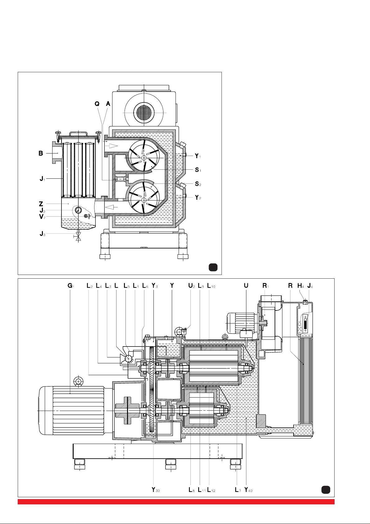
3.2 Construction (fig. 3 and 4)
VWZ pumps are constructed in five main sections, i.e. gear box (Y3), compression
stages (S1, S2), oil supply (L1 to L12), cooling system (R, Y40, R1) and separator
systems (Z, J1, J2, J3) on the suction side and exhaust side (optional). The pumps
are water cooled. The built in pressure relief valve (Q) permits start-up and
operation of the pumps over the entire vacuum range.
3
A Vacuum connection
B Exhaust connection
Drive
G
1
H4Cooling liquid filling cap
and pressure relief valve
I4Cooling liquid check
J1Filter candles in oil mist separator
J2Manometer for oil mist separator
J3Drain cock for oil mist separator
L Oil pump
L1Oil pump feed line
L2Oil pump leakage line
Lubrication (LP) stage drive end
L
3
L4Lubrication (LP) stage non-drive end
L5Lubrication (HP) stage drive end
L6Lubrication (HP) stage non-drive end
L7Bearing lubrication (LP) stage
L8Bearing lubrication (HP) stage
L9,L10Lubrication pump chamber and
slot (LP) stage
L11,L12Lubrication pump chamber and
slot (HP) stage
Q Pressure relief valve
R Heat exchanger
R1Fan
S1Low pressure stage (LP)
High pressure stage (HP)
S
2
U High temperature and operating
temperature thermostat
U2Cooling liquid de-aeration
V7Level control condensate / oil
Y Fresh oil tank
Y1Bearing oil tank (LP) stage
Y2Bearing oil tank (HP) stage
Y3Gear box unit
Y30Gear box oil
Y40Cooling liquid
Z Oil mist separator
Page 4
4

3.3 Data sheets and spare parts lists
see following data sheets:
D 134 / DA 134 (USA) External cooling ➝ VWZ 702 – VWZ 1202 (14)
D 137 / DA 137 (USA) Circulation cooling ➝ VWZ 702 – VWZ 1202 (13)
see following spare parts lists:
E 165/1 Parts for fundamental Units
E 165/2 Drive and gearbox
E 165/3 Radiator cooling
E 165/4 Oil supply
E 165/5 Fresh /External Cooling
3.4 Optional extras
Vacuum side:
• butterfly valve
• bleed valve
• solid/liquid separator
• condenser
Exhaust side:
• oil mist separator
• condenser
General:
• control with pre and post run- flushing unit with integral add. oil tank
• automatic condensate drain
3.5 Typical field of applications
• vacuum - drying
• vacuum - distillation
• vacuum - crystallisation
• vacuum - degassing
• vacuum - packing of moist products
• concentration of liquids, juices and extracts
Z ➝ Oil mist separator
➝ Flushing unit with integrated
Z
1
add. oil tank
Z
1
Z
Page 5
7

4. Method of operations
4.1 Pump
The compressor unit of the VWZ is a fresh oil, once through lubricated, rotary vane type pump. The flow direction is from top to
bottom, so that any contamination in the suction stream or condensate is readily discharged.
4.2 Pressure relief valve
The spring loaded pressure relief valve is located between the LP and HP stages. The function of the valve is to prevent an overpressure occuring between the LP and HP stages when the suction pressure is atmospheric. This over-pressure would occur as
a result of the higher capacity of the LP stage, compared to the HP stage. With the valve open the gases pass directly into the
exhaust, by-passing the second stage. As the suction pressure reduces the pressure differential between interstage and exhaust
becomes insufficient to hold open the valve, which closes progressively. When the interstage pressure drops to atmosphere or
lower, then full two stage compression is in operation.
4.3 Oil lubrication
The bearings of the LP and HP stages and the gear wheels, each have their own separate oil lubrication supply.
The compression chambers of the vacuum pump are continually fed with a metered fresh oil supply, from an oil metering pump.
This oil is exhausted from the pump together with the gas stream and separated out.
4.4 Shaft seals (fig. 9)
Shaft sealing rings (9c) are fitted on both
ends of the rotor shaft (9a) to seal of the
stage (9b). These sealing rings are
mounted on exchangeable shaft sleeves
(9d, 9e) together with the back up mechanical seals (9f). A further shaft sealing
ring (9h), seals off the coupling area (9k)
on the drive side. The shaft sealing rings
(9m) prevent the leakage of oil from the
gear box (9n) along the gear shaft (9p).
9
5. Installation
5.1 Mechanical Installation
5.1.1 Mounting (see data sheets D 134 + D 137)
Pumps that have reached operating temperature may have a surface temperature of more than 70°C depending on
a set temperature at the thermostat. Especially the cooling water jacket might be very hot. WARNING! Do Not Touch.
The VWZ is vibration free so a special foundation fastening is not necessary. When positioning the pump, it is important to ensure
that it is mounted horizontally and that there is easy access for routine checking of instruments, topping up of oil and water systems
and for repair work on the motor pump. A clearance of 0.5 m should be allowed to the nearest wall to ensure free entry (E) and
exhaust of the cooling air (F). The ambient temperature where the pump is installed should not exceed 40°C.
Further we recommend a clearance of approx. 0.3 m from motor and approx. 0.6 m to the nearest wall for maintenance.
The VWZ pumps can only be operated reliably if they are installed horizontally.
For operating and installation follow any relevant national standards that are in operation.
5.1.2 Suction Side (see data sheets D 134 + D 137)
The suction pipework should be connected at (A) (standard ISO-Flange). This suction line should be as short as possible, but
if it is more than 5 m, than a larger diameter than that of the pump flange should be used. The pipe layout should be such that
there is no strain on the pump, if necessary use flexible section. Appropriate separators should be fitted to protect the pump from
suction of solid particles and liquids (see accessories).
Solid particles of more than 5 µm and liquid slugs are able to destroy the compressor stages.
5.1.3 Exhaust (see data sheets D 134 + D 137)
If an oil mist separator is fitted the exhaust pipework is connected at (B). If an oil mist separator is not required then the pipework
is connected directly at B. In this case the pipework should be laid so that it drains away from the pump. If it is necessary for the
exhaust pipework to rise, then a catchpot should be fitted as near to the pump as possible, to collect condensate. This pot should
have drainage point of a diameter of at least
an automatic drain valve or a shut down sequence so that a build of condensate which could flow back into the pump is prevented.
The exhaust resistance within the pipework should not exceed 0.3 bar overpressure.
3
/4". It is also advisable to fit a level switch below the pump exhaust level to operate
Page 6

5.2 Electrical Installation
5.2.1 General (see data sheets D 131 + D 137)
The electrical data can be found on the data plate (N) or the motor data plate. The motors correspond to DIN/VDE 0530 and have
IP 54 protection and insulation class B or F . The connection diagram can be found in the terminal box on the motor. Check the
electrical data of the motor and the control gear for compatibility with your available supply (voltage, frequency, permissible current
etc.).
Connect the motor to the incoming supply. It is advisable to use thermal overload motor starters to protect the motor and wiring.
All cabling used on starters should be secured with good quality cable clamps.
We recommend that motor starters should be used that are fitted with a time delayed trip resulting from running beyond the
amperage setting. When the unit is started cold overamperage may occur for a short time.
The electrical installation must only be carried out by a qualified electrician under the observance of EN 60204. The
main switch must be provided by the operator.
5.2.2 Approximate values for setting motor overload protection
The approximate values for setting motor overload protection should be obtained from the motor manufacturer or
motor nameplate.
5.2.3 Electrical connections for the motor and control equipment
All electrical connections for the motor and control equipment are located in the terminal box. Each connection terminal is
numbered and these correspond as designated for each control item (as shown in the circuit diagram fig. 10). If any work is carried
out then the re-connection should be in accordance with this numbering system. Problems with function can be prevented and
faults are easier to find.
5.2.4 Terminal Box Connections Closed Circuit Cooling
1 2 3 4 5 6 7 8 9 1011121314151617181920212223242526
X1
operating thermostat
Fresh or External Cooling without Fanmotor ➝ without fan motor and
Suction valve
Bleeding valve
Valve flushing unit
Valve fresh oil
Valve oil mist separator
Reserve
Safety thermostat
Page 7
Operating thermostat
Level pre-separator
Level flushing liquid
Level cooling water
Level oil mist separator
Level fresh oil
Reserve
10

6. Normal Operation
6.1 Cooling Liquid
Y
5
Y
25
41
T
1
V
4
U
U
6.1.1 Fresh or External Cooling (fig. 12)
For starting-up the pump (VWZ 702 - VWZ 1202 (14))
first the water supply has to be connected to the hose
D
connection point (C). The water jacket (Y4) is filled by
pressing the spring loaded priming valve (U4). This
valve must be depressed until the water flows from
the hose outlet (D). The outlet hose may then be
connected. If rigid pipework has been connected to
the inlet and outlet points, then the bleed plug (U25)
should be loosened to allow the air to escape during
the priming operation and to ensure that the water
jacket is filled. This plug should be closed when the
water starts to seep from it. The water outlet pipe
Y
4
connected to outlet (D) should exert no back pressure on the water jacket (Y4).
Cooling liquid pressure higher than 0.3 bar
causes cracking of the water jacket.
The flow of cooling water through the jacket is
controlled by the thermostatic valve (U3) and its
sensor (U31) which can be set to operate in the range
U
3
C
50°C-90°C. The set temperature, which is chosen
according to the process conditions, will be constantly maintained by the system and can be read off
on the thermometer (T) at the top of the water jacket.
If for any reason the temperature should rise above
this, the high temperature cut-out (U1) will shut the
pump down at a temperature of 90°C. This temperature is set in our works and should not be adjusted.
If a higher temperature is required to suit process
12
U
K
51
4
U
5
U
4
conditions please contact the manufacturer.
In order to keep the thermostatic valve clean a dirt
filter (U3) is fitted. This must be cleaned periodically,
U
U
21
2
Y
41
R
42
1
I
4
H
RY
4
depending on the water quality. To do this unscrew
the nut (U51) and clean the element.
6.1.2 Closed Circuit Cooling (fig. 13)
U
2
For starting-up the pump (VWZ 702 - VWZ 1202 (13)):
The recommended coolant is a 50% antifreeze mix
which is poured into the heat exchanger at point (H4)
to a level midway up the upper sight glass (I4). The
filling should not take place under pressure and the
antifreeze should be well mixed beforehand. The
quantity required is shown on the data sheet D 137.
The coolant can be drained by opening the drain
cock (K4) on the water jacket (Y4) after removing the
vent plug (K41) at the cooler (R). To ensure complete
U
26
U
filling the bleed plug (U26) should be loosened.
6.1.3 Cooling Liquid Control (fig. 12 and 13)
The safety thermostat (U
) controls the temperature
1
of the coolant at the pump (fresh or external cooling).
When the pump is running, the safety- and operating
temperature thermostat (U) controls the switching on
and off the radial fan (R1) to maintain the pump at a
constant set temperature. When the pump is operating a slight pressure (approx. 0,3 bar) builds up in the
cooling system. The safety valve (H4) prevents this
pressure rising any further. Any air bubbles which
13
Y
Y
5
4
K
4
K
41
have formed during first filling or re-filling can escape
through the bleed valve (U2). For this to operate the cap (U21) on top of the valve should be unscrewed 2 to 3 turns.
If the location of the pump is such that there is a danger of freezing, then appropriate measures should be taken for both fresh
cooling and closed circuit cooling. The operating temperature can be set at according to process requirements between 50° and
80°C. If however, the operating temperature should continue to rise, the high temperature thermostat will shut down the pump
at a temperature of 90°C. If a higher temperature is required to suit process requirements, please contact the manufacturer.
Page 8

6.2 Oil Lubrication (see data sheets D 134 + D 137)
The pumps are despatched with the oil tanks (except fresh oil) filled. However
it is advisable to check the oil levels.
Sight glass: Fresh oil (I), LP-bearing (I1), HP-bearing (I2), gearbox (I3). If oil
level is low, please refill. Oil filling points: Fresh oil (H), LP-bearing (H1), HPbearing (H2), gearbox (H3). An oil level switch (V) is fitted in the fresh oil tank
as standard. This automatically stops the pump if the minimum oil level is
reached (depending on actual site control installation). The pump can be restarted after refilling. We recommend the following oil brands: Bechem VBL
100, BP Energol RC 100, Esso rotary oil 100, Mobil vacuum pump oil heavy,
Shell Tellus oil C 100 or Aral Motanol HK 100. Other lubricants should only
be used after reference to the manufacturer. The bearing and gear oil should
be completely changed once a year. Under extrem conditions we recommend
earlier maintenance if necessary. Oil type plate (M), oil drain LP-stage (K1)
and HP-stage (K2). The gearbox oil should be changed after approx. 3000
operating hours (K3).
Recommendations for cheking the fresh oil consumption: Fill up fresh oil to
the upper level indicated on the sight glass (I). Operate machine for a period
of 10 hours. Refill fresh oil again to the upper level.
Oil consumption = Refill / 10 hr
Old and used oil must be disposed of corresponding with the
relevant health, safety and environmental laws.
If the oil brand is changed. The old oil must be drained completely from
the tank and the oil cooler.
6.3 Oil metering pump
The oil metering pump is set to necessary output at the factory.
This rate can only be changed on request to our Company.
This rate can only be changed on request to our Company by turning the regulating screw. The capacity will be changed about
1
/3 per revolution. Reduce oil counter-clockwise, increase oil clockwise.
Before first start-up of the pump, the oil flow should be primed by giving the oil pump handle approximately 150
- 200 turns. This procedure should also be carried out if the pump has been stationary for a week or more, or after
repairs to the gear unit or change of stages or after cleaning of the oil pump or the oil lines.
Oil metering pump
Reduction of oil Increase of oil
Oil Consumption for VWZ and VPA (VWZ + Roots booster): l/h
VWZ 702 1002 1202
50 Hz
60 Hz
6.4 Initial Operation
Warning –> Start-up with pipework
At start-up, severe damage may occur if there is debris in
the pipework.
We therefore recommend a vacuum tight inlet filter of 5
micron rating is installed for start-up.
Start the pump momentarily to check the direction of rotation
(arrow (O ➞ D 134 + D 137)). As an option the motor coupling
can be fitted with a unidirectional free-wheel device to prevent
the vacuum pump rotating in the event of incorrect motor
rotations.
Important: When the pump is handling moist or aggressive
media, it should be run before and after the process operation
with a closed process vacuum valve, but with an open bleed
valve (optional item). This pre and post running should take 20
to 30 minutes. The pre run is to bring the pump up to operating
temperature and therefore prevent condensation of vapours
inside the pump. The post run is to purge the pump of residual
media and to leave the internals with a film of clean oil for the
period it will be stationary.
0.342 1.094 1.367
0.410 1.312 1.640
VPA 702. ... 1002. ... 1202. ...
50 Hz
60 Hz
7. Maintenance
When maintaining these units and having such situ-
ations where personnel could be hurt by moving
parts or by live electrical parts the pump must be isolated
by totally disconnecting the electrical supply. It is imperative that the unit cannot be re-started during the maintenance operation.
Do not maintain a pump that is at its normal operating
temperature as there is a danger from hot parts or hot
lubricant.
Hazardous substances must be removed before serving.
Maintenance personnel should be informed regarding the
presence of anything harmful and also be informed about
all relevant safety regulations before carrying out any
work.
7.1 Oil Metering Pump
The lubrication oil pump requires no special attention during
operation. Care should be taken to ensure that there is always
sufficient oil in the reservoir so that air is not pumped into the
oil lines. If this should occur the oil lines must be dis-connected
and the pump hand operated to remove all air bubbles from the
lines before re-connecting.
At least once a year the oil pump should be cleaned out by
pumping petroleum through it. At the same time the oil reservoir
should be flushed out. This cleaning is also recommended if the
pump has been stored for a long time after delivery before
putting into operation as hard deposits may have formed which
could adversely affect the pump performance.
0.427 2.280 2.848
0.513 2.736 3.417
Page 9

7.2 Oil Mist Separator (Optional Extra Exhaust Side)
The oil mist separator which is mounted directly on the
exhaust flange of the vacuum pump is a 2-stage device:
Separation:
➞ liquid droplets in the condensate collector
➞ aerosol in the filter elements
The oil mist separators are available in 2 material variations for the chemical and pharmaceutical industries:
➞ Stainless steel: 1.4541 ➞ glass
The filter candles are made of teflon or borosilicate glass
and hence are fully resistant to solvents and largely
resistant to acids.
J
4
Please note: If the material being handled is subject to
polymerisation or resin hardening it is not advisable to use
this type of oil mist separator as the filter elements would
quickly become blocked and would require frequent changing.
7.2.1 Oil Mist Separator Maintenance (fig. 14)
If the backpressure on the vacuum pump as shown on the
J
1
J
5
J
6
gauge (J2) rises to 0.5 to 0.6 bar then the filter candles (J1)
should be changed and the vessel (J4) cleaned out.
To change filter candles: after releasing the clamp screws
(J5) the oil mist separator cover (J6) and o-ring (J7) can be
removed. Remove the thumb wheels (J8) and take off the
locating plate (J9). Remove the filter candles (J1) and
J
7
J
J
8
9
J
J
2
V
3
7
before replacing the o-ring (J7) check it with particular
attention. During normal operation of the pump it is important to ensure regular draining of the condensate and oil
Q
A
1
mixture from the base of the separator and this can be
arranged for manual or automatic operation. A level switch
(V7) is fitted as standard and this will shut down the pump
when the exhaust condensate level becomes too high. For
the drain cock (J3) as shown a solenoid valve is available
for automatic drain of oil/condensate as an optional extra.
8. Trouble Shooting
8.1 Pump Overload
1. Check oil level in gear box (only when pump is stopped),
if necessary drain down to normal.
2. Measure back pressure in exhaust lines, if necessary
change filter elements.
3. Check ease of rotation of gearbox and pumpstages:
➝ remove motor and turn coupling.
8.2 Drop Off of Vacuum (pict. 15)
• Measure the vacuum directly at the vacuum connection (A), if necessary change mesh (A
).
1
X
Q
1
• Measure the back pressure on the pump exhaust (B1).
It should not exceed 0.3 bar.
• If the ultimate vacuum was not achieved in the first
test:
- remove suction flange (X1), loosen circlip (A2), remove mesh (A1) and clean.
- remove inter-stage relief valve (Q) at (Q1) and check
Q
B
2
1
A1A
2
operation as well as position of the valve.
• Measure the vacuum between the stages using tapping (Q2). If the same reading is obtained at suction flange (A) and (Q2)
then the LP stage is not functioning. If the reading at (Q2) is closer to atmospheric pressure, then the HP stage is not
functioning.
8.3 High Oil Consumption
• In case of bearing oil loss check the shaft seals between bearing and compressor stage and change (see page 14)
• High fresh oil consumption, check the non-return valves in the oil lines for correct function and replace. Disconnect oil lines
and check if they are under vacuum.
14
15
Page 10

REPAIR INSTRUCTIONS
1. Removal and Re-assembly of Water Jacket (fig. 12, 13 and data sheets D 134 + D 137)
• Switch off VWZ and vent to atmospheric
pressure
• Open plug (U25) or (U26).
• Drain off cooling liquid:
- VWZ (14) ➝ drain cock (K4).
- VWZ (13) ➝ drain cock (K4). Drainage is
completed by opening plug (K41) at the base
of the radiator (R).
• Disconnect the cables of following devices
at the terminal box (G) :
- VWZ (14) ➝ thermostat (U1) and level switch
(V4).
- VWZ (13) ➝ thermostat (U), level switch (V4)
and fan (R1).
- Disconnection is unnecessary if you have a
cable conduit and open the cover.
• Remove plug (Y42) and turn eye bolts M 12.
• Support the water jacket at eye bolts (Y
42
) by
S-shaped hooks and crane.
• Remove the allen bolts (Y41) with an extended allen key (approx. 1 m).
• Separate the water jacket (Y4) from the
connection cover (Y5) with a crane and place
on wooden blocks.
• Refit the water jacket in the reverse order.
• Use new sealing rings if necessary.
• Fill with coolant at (H4).
2. Changing LP and HP Stages (fig. 20)
• Removal and Refitting of LP and HP stages are the same.
2.1 Removal of Stages
• Remove water jacket (see above).
• Drain bearing oil:
- LP Stage at (K1) / HP Stage at (K2).
• Support stage (S
) or (S2) by slings from crane.
1
• Remove allen bolts (S11) or (S21).
• With gentle rocking movements, withdraw stage from flange complete with half coupling.
2.2 Refitting of Stages
• Before refitting, clean out the connecting passage ways (Y55) in the connection cover (Y5).
• When not replacing the stages, the ports (S15 fig. 27) must be cleaned, taking care that no dirt enters the compression
chambers (S16 fig. 27).
• Lightly smear both faces of gasket (30) with anti-seize, non-setting universal jointing compound (see E165/1).
• Refitting is reverse of removal.
• Use new sealing rings if necessary.
• Fill bearing oil tanks:
- LP stage at (H1) / HP stage at (H2).
• Refit water jacket (see above)
3. Removal and Reassembly of Drive (fig. 21)
• Disconnect cable of motor (G1).
• Remove hex-nuts (G11) and withdraw motor from mounting flange
(G2) with half coupling (G3).
• Remove hex-nuts (G51) from mounting flange (G2)
and separate from base frame (G5).
• Remove hex-nuts (G21) and withdraw
mounting flange (G2) from gearbox housing (Y3).
• The half coupling (G3)
can now easily be
reached.
• Refit in reverse order.
H2H
Y
1
5
G
2
Y
55
S
21
´
`¸
S
1
S
11
S
2
Y
3
20
G
G
11
1
G
51
G
5
G
3
21
Page 11

4. Changing Coupling Rubbers and Pins
4.1 On Drive Motor (fig. 22 and 23)
• Removal and reassembly of drive (see page 12).
• Remove circlips (38) and pull off coupling rubbers (37), replace if
necessary.
• Remove circlips (87).
• Withdraw half coupling (G3) from shaft (72) with a puller.
• Remove nuts (41) and spacer (40).
• Withdraw coupling pin (36) and replace, if necessary.
• Reassemble in reverse order.
(see also E 165/2)
4.2 On Stages (fig. 22 and 24)
• Removal and reassembly of water jacket (see page 12).
• Removal and refitting stages (see
page 12).
• Remove circlips (38) at half coupling (G
ber (37), replace if necessary.
) and pull off coupling rub-
4
72 23
87 G
3
• Remove nuts (41) and spacer (40).
• Withdraw coupling pin (36) and replace, if necessary.
• Reassemble in reverse order.
(see also E 165/1)
37 36
3938
40 41
22
G
4
24
454944
2548
W 2942
25
5. Repairs to stages, Non-Drive End (B)
5.1 Removal of Bearings and Seals (fig. 25)
• Removal of water jacket (see page 12).
• Drain bearing oil
- LP Stage at (K
- HP Stage at (K2)
• Disconnect oil lines (44, 45, 48, 49) or (59, 60, 63, 64) from
cover B (25) or (55). Bend oil lines away sufficiently to allow
dis-assembly of the cover B.
• Remove bearing cover (29).
• Put shaft seals (28) and, if existing, spacer (42) aside.
• Unscrew the allen screws on cover B (25) or (55).
K
K
2
1
• Screw the puller (W) to the cover B.
• Separate the cover B with bearing and seals from the shaft
end (3) or (52).
(see also E165/1 and E165/4)
)
1
Page 12

5.2 Reassembly of Bearings and Seals (fig. 26)
• Before reassembly all parts should be removed from the end cover (25) or (55).
Check parts (Pos. 10, 11, 12, 13, 14, 15, 17, 23, 28, 48) and if necessary replace.
• Fit new oil seal (10) with assembly device (W5) into end cover (sealing lip see fig. 26).
• Place sleeve type I (W
• Measure axial clearance between end cover and shaft according to the old seals (9) or (59) or calculate (length of housing
+ seals (9 or 59) - rotor = clearance). The axial clearance is set at works and fixed with dowels. If major work is necessary
on the housing, the tolerance given can be achieved by adjusting and pinning of housing and end cover.
• Important! To ensure correct and safe operation of the pump the data shown in the schedule below must be observed.
Please note different sizes of packing (9) or (59).
• Coat both sides of gasket (9) or (59) with anti-seize non-setting universal jointing material and position on end face of cylinder
housing (1) or (51).
• Push end cover over the dowels (2) and screw down loosely.
• Insert shaft seal(12) with sleeve in wearing disc (11).
• Insert wearing disc(11) together with o-ring (13) in bore of end cover with sleeve type I (W
• Insert shaft seal(12) with sleeve in sliding ring (15).
• Slightly oil seal surface of wearing disc(11) and sliding ring (15).
• Insert sliding ring (15) up to the wearing disc(11) and pull off sleeve type I (W
• Slightly oil spring(20) and insert in bore of transporting ring B (17).
• Place the transport ring B (17) over the shaft end, insert sleeves (19) in the bore of the sliding ring (15).
• Place spacer (43) if available next to transport ringB (17).
• Fit spacer ring (14) and bearing (26).
• Fit shaft nut(27) at shaft end (3) or (52) with necessary turning moment.
• Place spacer (42), if required, next to bearing (26).
• Bearing cover (29) with O-ring (23) slip carefully over the shaft and tighten down.
• Tighten end cover and re-connect oil lines.
• Re-fitting of stages and water jacket (see page 12).
) on shaft end (3) or (52) and lightly oil.
1
).
1
).
1
VWZ
702
1002
1202
1
23
B-side Fix
clear.
0.
10
9
Clearance data of st ages [mm]
Axialspalt Radial clearance
LP-stage HP-stage LP-stage HP-stage
W
1
Total
clearance
70
0.
0.
90
0.
90
B-side Fix
clear.
0.
10
Total
clearance
60
0.
0.
80
0.
80
(between rotor and housing)
0.20 0.30
0.20 0.35
0.20 0.35
25
W
5
11
15
12
19
48
17
13
10
12
20
43
26
23
27
28
29
14
Sleeve type I [mm]
42
26
Page 13

6. Changing Blades (fig. 27)
• Removal of water jacket and non-drive end B of compressor stage (see page 12 and 13)
• Withdraw blades (S31) and examine.
• Important! If required, replace blades only in
sets.
• Insert blades in rotor slots (the bevelled side
of the blades have to be at the rotor surface).
• Slightly oil blades before assembly. Blades
should move easily in rotor slots.
• Re-assembly of non-drive end B of compressor stage and water jacket (see page 12 and
13).
S
15
S
16
S
31
S
15
27
7. Repairs to stages, Drive End A
• HP and LP stages are constructed similarly.
7.1 Removal of Bearings and Seals (see fig. 28 and E 165/1, E 165/4)
• Removal of water jacket and compressor stage (see page 12).
• Disconnect oil lines on end cover A (8) or (54) and bend oil lines away sufficiently to allow dis-assembly of the cover.
• Remove threaded pin (45) from the coupling (35) and pull coupling from shaft end using a puller.
• Remove screws from bearing cover (22) and remove bearing cover with spacer (7).
• Unscrew plug (98) with sealing ring (99).
• Remove threaded pin (18) with allen key (3 mm).
• Remove screws in the end cover (8) or (54).
• Using a puller, free the end cover with the seals and the outer ring (21) from shaft end (3) or (52).
45
35
23
W
22
14
18
24
W
2
21
W
1
8
7
6
19
9
11
16
20
15
12
13
1
12
10
W
18
5
99
98
28
Page 14

7.2 Re-assembly of Bearings and Seals (see fig. 28 and 29)
• Before re-assembly all parts should be removed from the end cover (25) or (55). Check parts (Pos. 10, 11, 12, 13,
14, 15, 16) and if necessary replace.
• Fit new oil seal (10) with assembly device (W5) in end cover (sealing lip see fig. 28).
• Place sleeve type I (W1) on shaft end lightly oil.
• Coat both sides of gasket (9) or (59) with anti-seize non-setting universal jointing material and position on end face
of cylinder housing (1) or (51).
• Push end cover over the dowels and screw down loosel,
• Insert shaft seal(12) with sleeve in wearing disc (11).
• Place wearing disc (11) together with O-ring (13) on the sleeve type I (W
) and insert in bore of end cover (25) or
1
(55).
• Insert shaft seal(12) with sleeve in sliding ring (15).
• Slightly oil surface of wearing disc (11) and sliding ring (15).
• Insert sliding ring (15) up to the wearing disc (11).
• Pull off sleeve type I (W
).
1
• Tighten end cover (25) or (55).
• Slightly oil spring (20) and insert in transport ring A (16).
• Place the transport ring A (16) over the shaft end, insert sleeves (19) in the bore of the sliding ring (15).
• Transport ring A (16) should be set so that the end of the threaded pin (18) will lock the transport ring A (16) in the
location on the inner ring (4) placed on the shaft end (see fig. 29)
• Fit threaded pin (18) and fix with screw locking material.
• Place spacer ring(14), outer ring with cylinder roll (21) in the holes of the end cover.
• Place sleeve type II (W
) to shaft end and slightly oil.
2
• Fit new oil seal (24) with assembly device (W6) into bearing cover (22) (sealing lip see fig. 28).
• Pull bearing cover (22) with oil shaft seal (24) and O-ring (23) over the sleeve type II (W
).
2
• Centre bearing cover (22) and screw down.
• Pull off sleeve II (W2).
• Place key (7).
• Place half coupling (35) and secure with threaded pin (45).
• Re-connect oil lines.
• Re-fitting of stages and water jacket (see page 12).
Sleeve type II [mm]
Sleeve type III [mm]
Page 15
18 4
29

8. Repairs to Gearbox
8.1 Removal and Re-assembly of Gearbox (fig. 30 and 31)
• Drain oil (see data sheets D134 + D 137).
- Fresh oil at (K) / Bearing oil LP at (K
) and HP at (K2)
1
- Gearbox oil at (K3)
• Remove drive motor (see page 12).
• Remove locking ring (87) on the drive shaft (72).
• Pull coupling (G
) from the drive shaft with a puller.
3
• Take out key (151).
• Remove allen screws in bearing cover (81) and withdraw bearing
cover from drive shaft (72) with sealing (83) (and shaft seal (82)).
• Dis-connect all oil lines from the oil pump (185) (marking
identification).
• Remove oil pump (185) with seal (88).
• Remove oil pump flange (80) with seal (83) (shaft seal (82) is
located in the flange (80)).
• Remove spring shim (79).
• Unscrew all screws in the gear box (70) - including those around
the coupling.
• With the puller (W
) loosen the gearbox housing (70) from the
7
locating pins (108) while turning the screws simultaneous and
remove it.
• Re-assembly in reverse order. Note the following:
- Bearing cover (80) and shaft seal (82) will be carefully pushed
without sleeve along the shaft.
- Bearing cover (81) and
shaft seal (82) will be
mounted with assembly
sleeve type III (W
).
3
• Re-assembly of drive (see
page 12).
• Refill with oil (see data
sheets D 134 + D 137).
- Fresh oil at (H)
- Bearing oil LP at (H
) and
1
HP at (H2)
- Gearbox oil at (H3)
70W
7
185 80 87 81G
3
30
W
26
72
73
G
3
W
8
9
8910875
31
8.2 Changing Gear Wheels and Ball Bearings in Gearbox
Housing (fig. 31 and 32)
• Removal and Re-assembly of gearbox.
• Withdraw both bearings (26) with a puller (W8) (do not use the
bearings again).
• Bend back locking tab (77).
• Remove shaft nut (78) with a C spanner (W9).
• Remove back locking tab (77).
• Pull off gear wheels (73) and (75).
• Assemble in reverse order.
• Before pressing on bearing (26) their inner ring should be
warmed to 100°C.
32
Page 16

8.3 Changing Bearings, Shaft Seals and Seals in Gearbox Connection housing (fig. 33).
• Removal and re-assembly of water jacket
and compressor stage (see page 12).
• Removal and re-assembly of gearbox (see
page 17).
• Remove the circlip (87) on the drive shaft
(72) and on the gear shaft (74).
• Remove the coupling (86).
• Remove shaft key (7).
• Remove the allen screws in the bearing
cover (81).
• Loosen and remove the bearing cover (81)
with two allen screws (M8) together with the
seal (83) and shaft sealing (82).
• Remove the spacer ring (79).
• Press the drive shaft (72) with bearing (26) and
gear shaft (74) with bearing (26) out of the intermediate housing in the drive direction, using a sleeve on the
outer bearing ring.
• Pull off and change ball bearings (26).
• The assembly is in the reverse order.
• Please note the following:
- Before pressing on bearing (26) their inner ring should be warmed to 100°C.
- When fitting the bearing cover (81) with the shaft seals (82) an assembly sleeve type II (W
should be used.
)
2
9. Other repairs
9.1 Cleaning the Suction and Exhaust Ports in Connection Housing (fig. 34)
• Switch off pump and bleed to atmospheric pressure.
• Remove the pipe work.
• Remove the separator (Z).
• Remove the flange (103) from the suction channel (Y
) (note seals (104)).
65
• Remove the hemispherical mesh (118) and clean (solvent).
• Both port areas (Y65 and Y66) can be cleaned through the openings in
the intermediate housing (89). (Please take care, that no dirt enters
the pump).
Y
65
• Assembly is in the reverse order.
9.2 Changing the Pressure Relief Valve (fig. 34)
• Remove allen screws in the valve (400).
• Carefully remove the valve (400) straight from the
intermediate housing.
• Check all parts and the valve seat in the connection
housing (89). If necessary, regrind the valve seat.
• Before re-assembly check that the valve (404) slides
easily in the valve sleeve (401).
• Assembly is in the reverse order.
33
Y
66
34
10 Instructions for storing fresh oil lubricated rotary vane vacuum pumps
Introduction
Start-up of all pumps delivered by Rietschle should be made within 3 months. If this is not possible, please observe the
following details, the guarantee given by Rietschle may be invalidated if not followed.
a. Storing of pumps
The store room for the pumps must be dry and free of all corrosive materials. The ambient temperature should be constant
and above 10°C.
b. Condition of Stored Pumps
The suction and discharge ports of the pumps should be sealed with blank flanges. All lubricating and sealing oil reservoirs
should be filled, in accordance with the instruction manual.
c. Maintenance during Storage
The pumps should be operated once a month for about 2 hours to prevent any kind of corrosion within the pump. Please
pay attention to the fact, that the blank flange from the discharge side is to be removed before operation and installed again
afterwards. The blank flange of the suction side should not be removed, since end vacuum should be reached.
d. Setting Pumps into Operation
A technical service made by Rietschle will be necessary for all pumps stored longer than 3 months. You will be responsible
for the costs of the inspection and test run. Further, all costs occurring from improper storage or handling will be charged.
Page 17
/ PM69.99
 Loading...