


Thomas 2660xxx807
A Thomas Industries Company
2660CE37-807 & 2660CGHI42-807
Compressor
Field Service Manual
©2003 Thomas Industries Sheboygan, Inc.
FSM 0159 Rev. A 07/04

2

A Field Service Manual
Prepared by
A Thomas Industries Company
Thomas Compressor
2660CE37-807 & 2660CGHI42-807
Field Service Manual
©2003 Thomas Industries, Sheboygan Inc. Field Service Manual FSM 0159
Rev. A 0704
Table of Contents
Page
Introduction ..................................................................................................................................................................... 4
Safety First ....................................................................................................................................................................... 5
Exploded View and Parts List..................................................................................................................................... 6 - 7
Preventive Maintenance and Troubleshooting Guide.................................................................................................9 - 10
Required Tools and Materials ........................................................................................................................................ 11
Component Repair ......................................................................................................................................................... 11
Servicing the Head or Valve Assembly.................................................................................................................... 11
Servicing the Connecting Rod Assembly and Eccentric Assembly ....................................................................... 16
Reassembling the Compressor ................................................................................................................................ 20
3

Introduction
This Field Service Manual is intended for use ONLY by properly trained and experienced repair personnel employed by an
authorized service center. THIS SERVICE MANUAL SHOULD NOT BE USED BY OR DISTRIBUTED TO THE PUBLIC.
THE INSTRUCTIONS AND WARNINGS HEREIN PRESUME EXISTING FAMILIARITY WITH THE DESIGN AND
FUNCTION OF THESE AND SIMILAR PRODUCTS, AND THEIR COMPONENTS.
Please Note:
The model(s) represented in this manual may have additions and/or modifications made at any time. Pictures represent a standard
unit series and an actual unit may vary slightly. This manual is based on the latest technical information available at the time of
creation or last revision. It is believed to be generally accurate and reliable. Consult the factory if additional detailed information
is desired, or whenever there is a question about a given unit’s configuration or performance specifications.
4

Safety First
It is recommended that you thoroughly read and understand this manual before you attempt to service the
Thomas series of compressors to which this applies. PLEASE NOTE THE FOLLOWING CAUTIONS
AND WARNINGS FOR YOUR OWN SAFETY.
Caution
To avoid personal injury and/or property damage, only authorized service personnel should
service this unit.
Warning
To avoid the risk of electrical shock, personal injury, or death, disconnect power before servicing this
unit.
Caution
To avoid personal injury, do not remove fan guards while unit is connected to power.
Caution
To avoid personal injury, especially to eyes and face, use eye and face protection when
servicing this unit.
Caution
To avoid personal injury, especially to eyes and face, never point the exhaust air flow at
yourself or other people in the area. Unit is capable of pressures of 100 psig.
Caution
To avoid damage, never lubricate any component in your compressor. All moving parts are
permanently lubricated.
Caution
To avoid property damage or personal injury, always try rotating the fan by HAND prior to
connecting the unit to the power source. Check for suction at the air inlet port by placing your
finger over the port as you turn the fan. You should feel a slight suction with each rotation
of the fan. If you dont feel suction, or if you feel or hear a thump as you turn the fan, DO NOT
CONNECT THE UNIT TO A POWER SOURCE. Review the assembly procedure for
possible error.
5
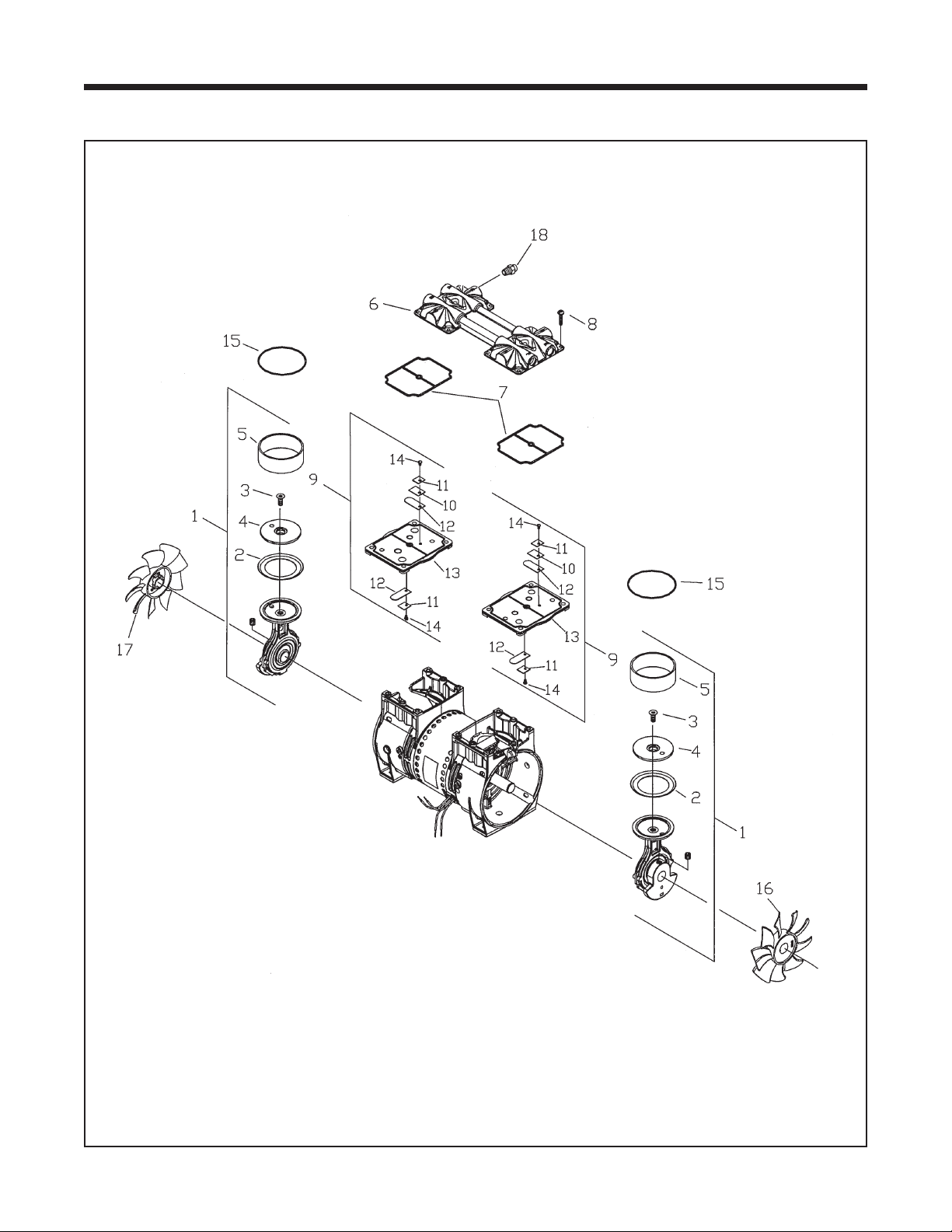
Exploded View and Parts List
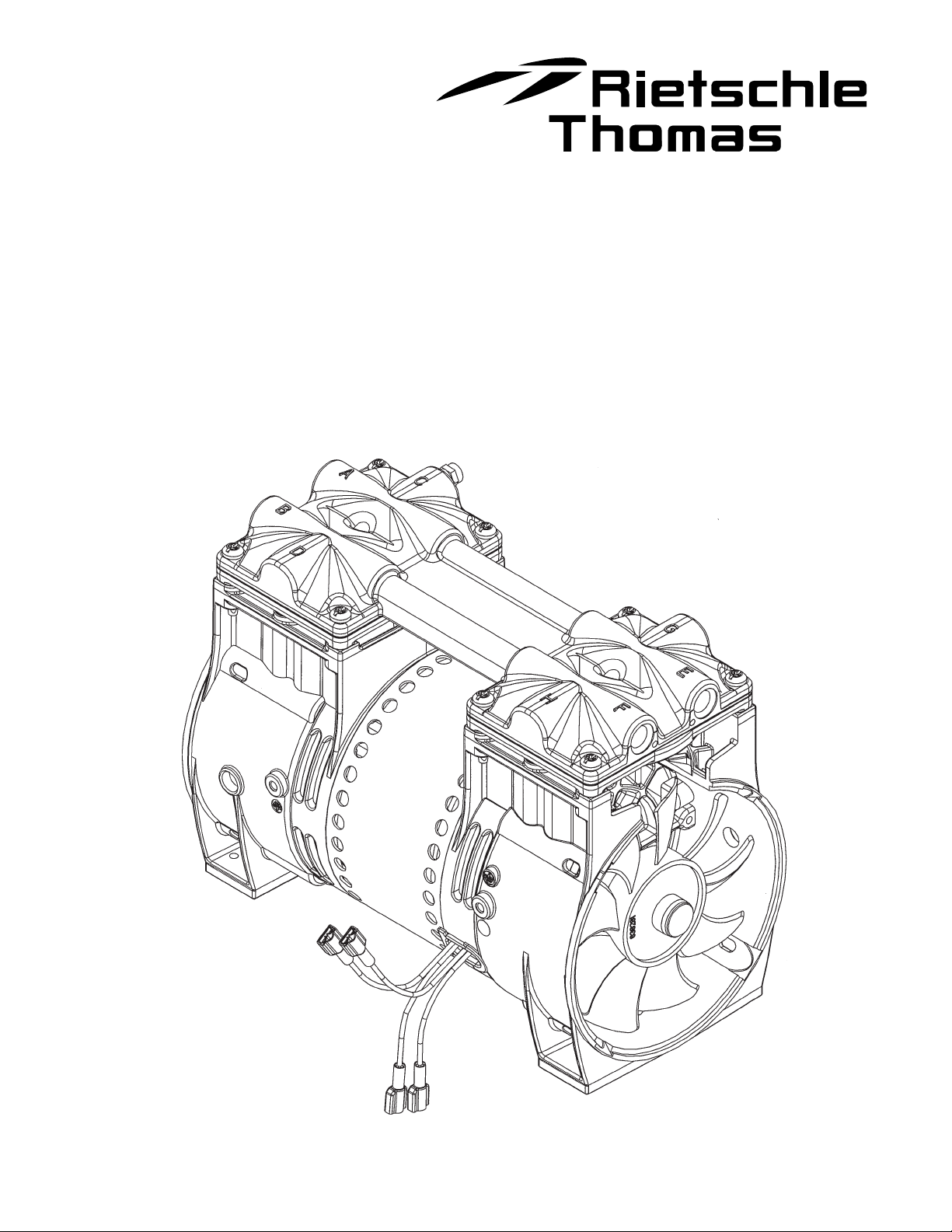
Exploded View of the Thomas 2660CE37-807 & 2660CGHI42-807 Series Compressor
6

Field Service Parts List for Thomas 2660CE37-807 & 2660CGHI42-807 Compressor
Item Part Qty. Qty.
No. No. Per Ass'y Per Unit Description
1 See Chart -- 2
2 624677 1 2 Piston Cup
3 625776 1 2 Screw - Piston Cup Retainer
4 626392 1 2 Piston Cup Retainer
5 618114 1 2 Cylinder Sleeve
6 610880 -- 1 Head
7 623143 -- 2 O-Ring - Head Gasket
8 625175 -- 8 Screw - Head
9 621591 -- 2 Valve Plate Assembly
10 617177 1 2 Valve Restraint
11 617562 2 4 Valve Keeper Strip
12 621485 2 4 Valve Flapper - Intake & Exhaust
13 621461 1 2 Valve Plate
14 625094 2 4 Screw - Valve Flapper
15 623137 -- 2 O-Ring Valve Plate
16 638282 -- 1 Fan - Black
17 638281 -- 1 Fan - Gray
18 638702 -- 1 Pressure Relief Valve
Connecting Rod, Eccentric & Bearing Assembly
Connecting Rod, Eccentric & Bearing Assembly Chart
1 666660 -- 2 For 2660CE37-807
1 666702 -- 2 For 2660CGHI42-807
7

Preventive Maintenance and Troubleshooting Guide
Thomas Industries recommends that you perform the following service to minimize unexpected downtime
for your compressor:
••
• Replace the connecting rods or piston cups and sleeves
••
••
•
••
••
• Replace the head gasket O-rings
••
Replace the flapper valves
••
•
••
Replace the valve plate O-rings
8
 Loading...