

RIDGID WL1200LS Operator's Manual

://6
23(5$725·60$18$/
WARNING: To reduce the risk of
injury, the user must read and
understand the operator’s manual
before using this product.
,1&+:22'
7851,1*/$7+(
SAVE THIS MANUAL FOR
FUTURE REFERENCE
Part No. SP6489 Printed in China

Table of Contents
Section Page
Table of Contents ................................2
Safety Instructions For Wood Turning
Lathe ................................................. 2
Safety Symbols ...................................3
Before Using the Lathe .......................3
When Installing Or Moving the Lathe .4
Before Each Use ................................4
To Reduce the Risk of Injury From
Jams, Slips Or Thrown Pieces
(Kickbacks Or Throwbacks) ..............4
Plan Ahead To Protect Your Eyes,
Hands, Face and Ears .......................5
Inspect Your Workpiece .....................6
Whenever Lathe Is Running ...............6
Before Leaving the Lathe ...................6
Motor Specifications and Electrical
Requirements ..................................7
Power Supply and Motor
Specifications ....................................7
General Electrical Connections ..........7
110-120 Volt, 60 Hz. Tool Information 7
Motor Safety Protection ......................8
Wire Sizes ..........................................9
Check Motor Rotation .........................9
Unpacking and Checking Contents ...9
Tools Needed .....................................9
Unpacking ...........................................9
List of Loose Parts ............................10
Assembly ............................................ 11
Assembling Steel Legset ..................11
Holes Used for Mounting Boards and
Wood Lathe to Leg Set ....................12
Mounting Left Side Table Top ..........12
Mounting Right Side Table Top ........13
Mounting Headstock .........................14
Mounting the Motor ...........................15
Headstock,Tailstock, and Tool Rest As -
sembly .............................................17
Mounting Rear Foot ..........................19
Spur and Cup Center Installation .....20
Check Spindle Rotation ....................21
Section Page
Adjusting Tailstock ...........................21
Aligning Centers ...............................21
Getting To Know Your Wood Lathe .22
On-off Switch ....................................23
Speed Chart .....................................23
Basic Lathe Operations ....................24
Changing Speeds .............................24
Spindle Turning ................................25
Faceplate Turning ............................27
Indexing ............................................29
How To Use Your RIDGID
Wood Lathe ....................................30
Woodworking Chisels and How to Use
Them ............................................... 30
The Six Commonly Used Chisel
Types ..............................................30
Selection Of Chisels .........................30
Theory Of Turning ............................30
Using The Gouge .............................33
Using The Skew ...............................33
Using The Parting Tool ....................34
Using The Scraping Chisels .............34
Hand Positions .................................35
Making Standard Cuts ......................36
How To Handle Spindle Turnings .....40
Duplicate Turnings ...........................41
Long Spindles ..................................42
Faceplate & Chuck Turnings ............42
How To Make Fancy Faceplate Turn-
ings ..................... ...... ..... ...... ............43
Sanding, Buffing And Polishing ........46
Wiring Diagram ..................................47
Maintenance .......................................47
Maintenance .....................................47
Lubrication ........................................47
Recommended Accessories .............47
Troubleshooting ................................ 48
General ............................................48
Motor ................................................ 49
Repair Parts .......................................51
Safety Instructions For Wood Turning Lathe
The purpose of safety symbols is to
attract your attention to possible
dangers. The safety symbols, and the
explanations with them, deserve your
careful attention and under sta ndi ng.
The safety warnings do not by
themselves eliminate any danger.
The instructions or warnings they give
are not substitutes for proper accident
prevention measures.
2

Safety Instructions For Wood Turning Lathe (continued)
Safety Symbols
DANGER: indicates an imminently
hazardous situation which, if not
avoided, will result in death or serious
injury.
WARNING: indicates a potentially
hazardous situation which, if not
avoided, could result in death or serious injury.
CAUTION: indicates a potentially
hazardous situation which, if not
avoided, may result in minor or moderate injury. It may also be used to
alert against unsafe practices that
may cause property damage.
NOTE: Advises you of information or
instructions vital to the operation or
maintenance of the equipment.
WARNING: Do not attempt to use the tool until you have read thorough-
ly and understand completely the operator’s manual. Pay close attention to
the safety rules, including Dangers, Warnings, and Cautions. If you use this
tool properly and only for what it is intended, you will enjoy years of safe, reliable service.
Before Using the Lathe
WARNING: Some dust crea ted
by power sanding, sawing, grinding, drilling, and other construction
activities contains chemicals
known (to the State of California)
to cause cancer, birth defects or
other reproductive harm. Some
examples of these chemicals are:
• Lead from lead-based paints,
• Crystalline silica from bricks and
cement and other masonry products, and
• Arsenic and chromium from
chemically-treated lumber.
Your risk from these exposures
varies, depending on how often
you do this type of wo rk. To reduce
your exposure to these chemicals:
work in a well ventilated area, and
work with approved safety equipment, such as those dust masks
that are specially designed to filter
out microscopic particles.
WARNING: To reduce the risk
of mistakes that could cause serious, permanen t injury, do not plug
the lathe in until the following steps
have been satisfactorily completed.
Know and Understand the Lathe
• Completely assemble and align lat he.
• Learn the use and function of the
ON-OFF switch.
• Review and understand all safety
instructions and operating procedures in this manual.
• Review the maintenance methods
for this lathe.
• Find and read the warning label
found on the lathe (shown below).
3

Safety Instructions For Wood Turning Lathe (continued)
When Installing Or Moving the Lathe
Reduce the Risk of Dangerous
Environment.
• Use the lathe in a dry, indoor place
protected from rain.
• K eep work ar ea well ligh ted.
To reduce the risk of injury from
unexpected lathe movement.
• The lathe and motor must be bolted
down to a stand or workbench for
stability.
• To reduce the risk of injury from
electrical shock, make sure your fingers do not touch the plug’s metal
Before Each Use
Inspect your lathe.
• To reduce the risk of injury from
accidental starting, turn the switch
off, unplug the lathe, and remove
the switch key before changing the
speeds, changing the setup, or
adjusting anything.
prongs when plugging in or unplugging the lathe.
• Turn off and unplug the lathe before
moving it to a new area. To reduce
the risk of back injury, get help when
you need to lift or move the lathe.
• Never Stand On Tool. Serious
injury could occu r if the tool tips or
you accidentally hit the cutter head.
Do not store anything above or
near the tool where anyone might
stand on the tool to reach them.
• Keep turning tools sharp. Dull or
nicked tools tend to dig in the wood,
causing the tool or workpiece to be
thrown.
• To reduce the risk of injury from
unsafe accessories, use only recommended accessories.
• Check for alignment of moving
parts, binding of moving parts,
breakage of parts, unit stability, and
any other conditions that may affect
the way the lathe works.
• If any part is missing, bent or broken
in any way, or any electrical part
does not work properly, turn the
lathe off and unplug the lathe.
• Replace damaged, missing or failed
parts before using the lathe again.
• Keep lathe interior free of wood
chips and dust buildup around
motor and switch box.
Use Recommended Accessories.
• To avoid injury from unsafe accessories, use only recommended
accessories.
• Consult the operator’s manual for
recommended accessories.
• Follow the instructions that accompany the accessories.
WARNING: Use only accessories recommended for this lathe.
(Using other accessories may be
dangerous.)
To Reduce the Risk of Injury From Jams, Slips Or Thrown Pieces
(Kickbacks Or Throwbacks)
When turning between centers or on
the faceplate:
- Always rough-out "out of round"
workpieces at slow speed.
4

- Running the lathe too fast, so that
it vibrates, could cause the workpiece to be thrown from the
lathe... or the turning tool to be
jerked from your hands.
Always revolve the workpiece by
hand before turning on the motor. If
the workpiece strikes the tool rest, it
could split and be thrown out of the
lathe.
Do not allow t he t urni ng to ol to "b ite "
into the workpi ece which cou ld result in
splitting of the workpiece or the workpiece being t hrow n from t he la the .
- Always position the tool rest
above the centerline of the lathe
for spindle turning.
- Do not apply the turning tool to
the workpiece below the level of
the tool rest.
Do not run the lathe in the wrong
direct ion. This could cause the turning tool to be thrown from your hands.
The lathe must run in a direction so
that the top of the workpiece turns
toward you.
Before attaching a workpiece to the
faceplate:
- Always "rough it out" to as "true
round" as possible. This will minimize vibration while turning.
- Always fasten the workpiece
securely to the face-plate.
- Failure to perform these set-up
operations could cause the workpiece to be thrown from the lathe.
Avoid awkward hand positions, where
a sudden slip could cause a hand to
move into the workpiece.
Remove all loose knots before installing workpiece between ce nters or on
the faceplate.
Never leave the lathe work area with
the power on, before the lathe has
come to a complete stop, or without
removing and storing the switch key.
Never operate the lathe with protective cover on the unused shaft end of
the motor removed.
Hang your turning tools on the wall
toward the tailstock end of the lathe.
Do not lay them on the bench so that
you must reach over the revolving
workpiece to select them.
Keep firm hold and control of the turning tool at all times. Special caution
must be exercised when knots or
voids are exposed to the turning tool.
Plan Ahead To Protect Your Ey es, Hands, Face and Ears
Reduce the Risk of Accidental
Starting.
• Make sure switch is “OFF” before
plugging lathe into a power outlet.
Dress for safety.
• Any power tool can throw foreign
objects into the eyes. This can result
in permanent eye damage. Always
wear safety goggles, not glasses
complying with ANSI Z87.1 (or in
Canada CSA Z94.3-99) shown on
package. Everyday eyeglasses
have only impact resistant lenses.
They are not safety glasses. Safety
goggles are available at many local
retail stores. Glasses or goggles not
in compliance with ANSI or CSA
could seriously hurt you when they
break.
• For dusty operations, wear a dust
mask along with safety goggles.
5

Safety Instructions For Wood Turning Lathe (continued)
• Do not wear loose clothing, gloves,
neckties or jewelry (rings, wrist
watches). They can get caught and
draw you into moving parts.
• Wear nonsl ip foot wear.
• Tie back long hair.
• Rol l lon g sleev es above the elbow.
• Noise levels vary widely. To reduce
the risk of possible hearing damage,
wear ear plugs or muffs when using
lathe for hours at a time.
Inspect Your Workpiece
• Think Safety.
• Complete hand sanding of the workpiece before removing it from the
faceplace. Never attempt to r emove
and then remount a faceplate turning to the faceplace for any reason.
It is not always possible to position
the turning on the faceplace exactly
the way it was originally and an outof-balance condition could result.
• Never attempt to remount a
between-centers turning if the original centers in the turning have been
altered or removed. Be positive the
lathe is set at the lowest speed if
remounting a between-centers turning with non-altered original centers.
• Use extra caution in mounting a
between-centers or sp ind le turni ng
to the faceplate, or a faceplate turning to between- centers, for subsequent operations. Be positive the
lathe is set at the lowest speed
before turning ON.
• Never mount a workpiece that contains any splits, checks, or loose
knots to a faceplate or between centers.
• Do not perform any operation when
hand holding the workpiece. Do not
mount a reamer, milling cutter, wire
wheel, or a drill bit to the headstock
spindle.
Whenever Lathe Is Running
WARNING: Don't allow familiar-
ity (gained from frequent use of
your lathe) to cause a careless
mistake. Always remember that a
careless fraction of a second is
enough to cause a severe injury.
• Before actually turning with the
lathe, let it run for a while. If it makes
an unfamiliar noise or vibrates a lot,
stop immediately. Turn the lathe off.
Unplug t he lat he. Do not re start until
finding and correcting the problem.
Keep Children Away.
• Keep all visitors a safe distance
from the lathe.
• Make sure bystanders are clear of
the lathe and workpiece.
Don’t Force Tool.
• Feed the tool into the workpiece
only fast enough to let the tool cut
without bogging down or binding.
Before freeing jammed material.
• Turn switch “OFF”.
• Wait for all moving parts to stop.
• Unplug the lathe.
Before Leaving the Lathe
• Turn th e lathe off.
• W ait for lathe to come to a complete
stop.
• Unplug the lathe.
• Make workshop child-proof. Lock
the shop. Disconnect master
switches. Remo ve t he ye llow swit ch
key . Store it away from children and
others not qualified to use the tool.
SAVE THESE INSTRUCTIONS
6

Motor Specifications and Electrical Requirements
Power Supply and Motor Specifications
This Lathe is designed to use a 1725
RPM motor only. Do not use any motor
that runs faster than 1725 RPM.
WARNING: To reduce the risk
of electrical hazards, fire hazards
or damage to the tool, use proper
circuit protection . Your tool is wired
at the factory for operation using
the voltage shown. Conn ect tool to
a power line with the appropriate
voltage and a 15-amp branch circuit. Use a 15-amp ti me dela y type
fuse or circuit breaker. To reduce
the risk of shock or fire, if power
cord is worn or cut, or damaged in
any way, have it repl aced immediately.
General Electrical Connections
The A-C motor used on this tool is a
totally enclose d fan cool ed (TEFC), induction nonreversible type, having the following specifications:
Rated H.P 1/2
Voltage 110-120
Amperes 8.0
Hertz (Cycles) 60
Phase Single
RPM 1725
Rotation of Shaft Clockwise
DANGER: To reduce the risk of
electrocution:
1. Use only identical replacement
parts when servicing. Servicing
should be performed by a qualified service technician.
2. Do not use in rain or where floo r
is wet.
This tool is intended for indoor
residential use only.
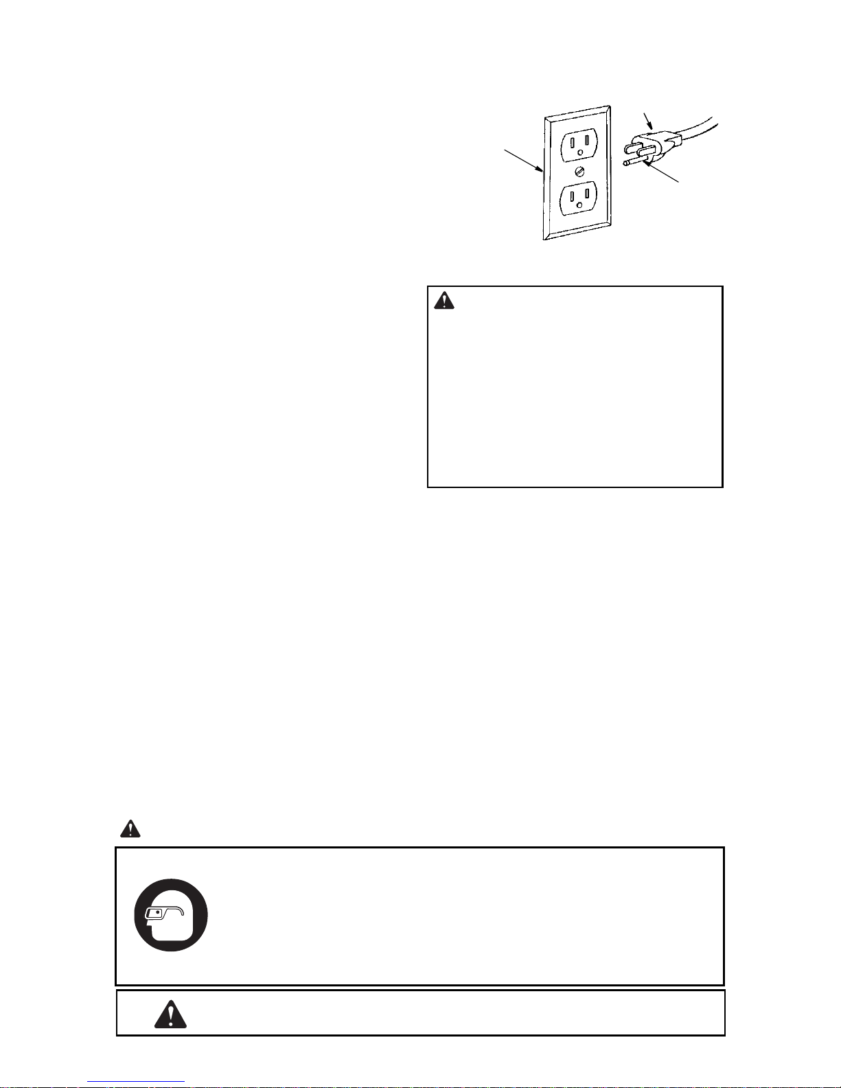
110-120 Volt, 60 Hz. Tool Information
NOTE: The plug supplied on your tool
may not fit into the out let you ar e plannin g
to use. Your local electrical code may
require slightly different power cord plug
connections. If these differences exist
refer to and make the proper adjustmen ts
per your local code before your tool is
plugged in and turned on.
In the event of a malfunction or breakdown, grounding provides a path of least
resistance for electric current to reduce
WARNING: To prevent electric
shock, do not permit fingers to
touch the terminals of plug when
installing or removing the plug to or
from the outlet.
the risk of electric shock. This tool is
equipped with an electric cord having an
equipment grounding conductor and a
grounding plug, as shown. The plug must
be plugged into a matching outlet that is
properly installed and grounded in accordance with all local codes and ordinances.
Do not modify the plug provided. If it will
not fit the outlet, have the proper outlet
installed by a qualified electrician.
7
Motor Specifications and Electrical Requirements (continued)
3-Prong Plug
Improper connection of the equipment
grounding conductor can result in a risk of
electric shock. The conductor with insulation having an outer surface that is green
with or without yellow stripes is the equipment grounding conductor. If repair or
replacem ent of the ele ctr ic c ord o r p lug is
necessary, do not connect the equipmentgrounding conductor to a live terminal.
If the grounding instructions are not completely understood, or if you are in doubt
as to whether the tool is properly
grounded check with a qualified electrician or service personnel .
Motor Safety Protection
1. Connect this tool to a power source
with the appropriate voltage for your
model and a 1 5-amp bran ch circu it with
a 15-amp time delay fuse or circuit
breaker. Using the w rong siz e fuse can
damage the motor.
2. If the motor won’t start, turn the switch
off immediately and unplug the tool.
Check the spi ndl e t o m ak e s ure it turns
freely. If the spindle will not turn make
sure the index pin is de sengag ed . (See
“Getting to Know Your Wood Lathe” Index Pin.) If the spindle is free, try to
start the motor again. If the motor still
does not start, refer to the "Motor Troubleshooting Chart."
3. Fuses may "blow" or circuit breakers
may trip frequently if:
a. Motor Is Overloaded-Overloading
can occur if you feed too rapidly or
WARNING:
Properly
Grounded
3-Prong Outlet
Grounding
Prong
WARNING: If not properly
grounded, this tool can cause an
electrical shock, particularly when
used in damp locations, in proximity
to plumbing, or out of doors. If an
electrical shock occurs there is the
potential of a secondary hazard,
such as your hands to hit the cutting
tool.
a. make too many start/stops in a short
time.
b. Line voltages should not be more
than 10% above or below the nameplate voltage. For heavy loads, however, the voltage at motor terminals
must equal the voltage specified for
your model.
4. Most motor troubles may be traced to
loose or incorrect connections, overload, low voltage (such as small size
wire in the supply circuit) or to overly
long supply circuit wire. Always check
the connections, the load and the supply circuit whene ver motor does n't work
well. Check wire sizes and length with
the Wire Size Chart shown.
The operation of any power tool can result in foreign objects being
thrown into your eyes , wh ich can result in severe eye dam ag e. Befo re
beginning tool operation, always wear safety goggles or safety glasses
with side shields and a full face shield when needed. We recommend
Wide Vision Safety Mask for use over eyeglasses or standard safety
glasses with side shields. Alwa ys wear ey e protection which is mark ed
to comply wtih ANSI Z87.1.
Look for this symbol to point out important safety precautions. It
means attention!!! Your safety is involved.
8
Wire Sizes
NOTE: Make sure the proper extension
cord is used and is in good condition.
The use of any extension cord will cause
some loss of power. To keep this to a minimum and to prevent overheating and
motor burn-out, use the table below to
determine the minimum wire size
(A.W.G.) extension cord. Use only 3 wire
extension cords which have 3-prong
grounding type plugs and 3-pole receptacles which accept the tool’s plug.
Extension Cord
Length
0-25 Ft.
26-50 Ft .
Gauge
(A.W.G)
16
14
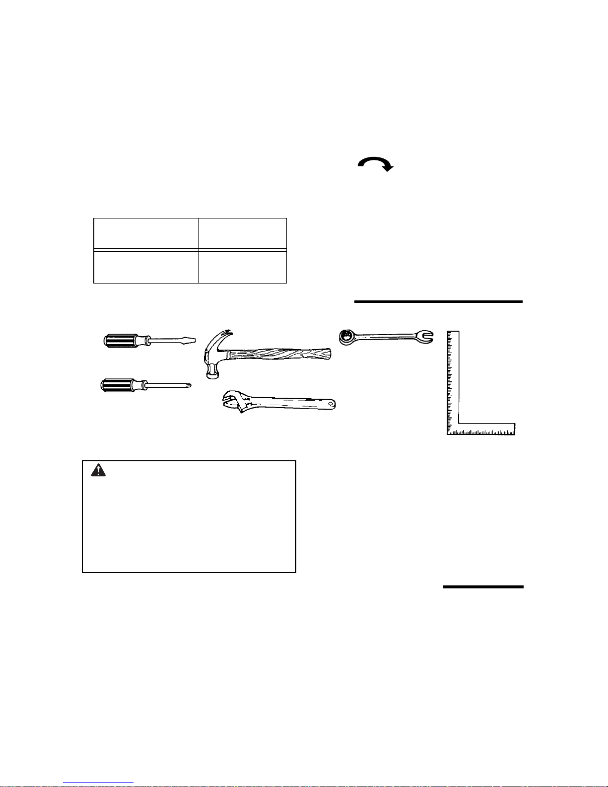
Check Motor Rotation
Place the motor on your workb enc h or on
the floor. Standing clear of the motor
shaft, plug the motor cord into a properly
grounded outlet. Noti ce t he rotati on of the
shaft. As you look directly at the motor
shaft it should be turning in the clockwise
direction. If the motor shaft is
turning clockwise, remove the plug from
the power outlet and continue the assembly procedures. If the motor is turning
counterclockwise, remove the plug from
the power outlet and contact 1-866-539-
1710.
Unpacking and Checking Contents
Tools Needed
Medium Screwdriver
Hammer
Phillips Screwdriver
Adjustable Wrench
Unpacking
WARNING: To reduce the risk
of injury from unexpected starting
or electrical shoc k, do not plug the
power cord into a source o f power.
This cord must remain unplugged
whenever you are working on the
wood lathe.
1. Unpack all t he parts of your wood l athe
NOTE: Make certain all items are
accoun ted for, before discarding any
packing material.
10mm Wrench
13mm Wrench
14mm Wrench
and lay them out in your work area so
they can be recognized easily. Check
all parts with the parts table and be
careful not to lose any parts during
assembly.
Unpacking and Checking Contents (continued)
List of Loose Parts
Item Description Qty.
A Belt Guard Assembly.......................1
B Headstock .......................................1
C Motor Pulley ....................................1
D V-Belt...............................................1
E Motor...............................................1
F Large Tool Rest...............................1
G Tool Rest Holder/Clamp Support
Assembly.........................................1
H Tailstock and Ram...........................1
J Rear Foot ........................................1
K Tube Or Bed....................................1
L S ma ll Tool Rest................. ...... ........1
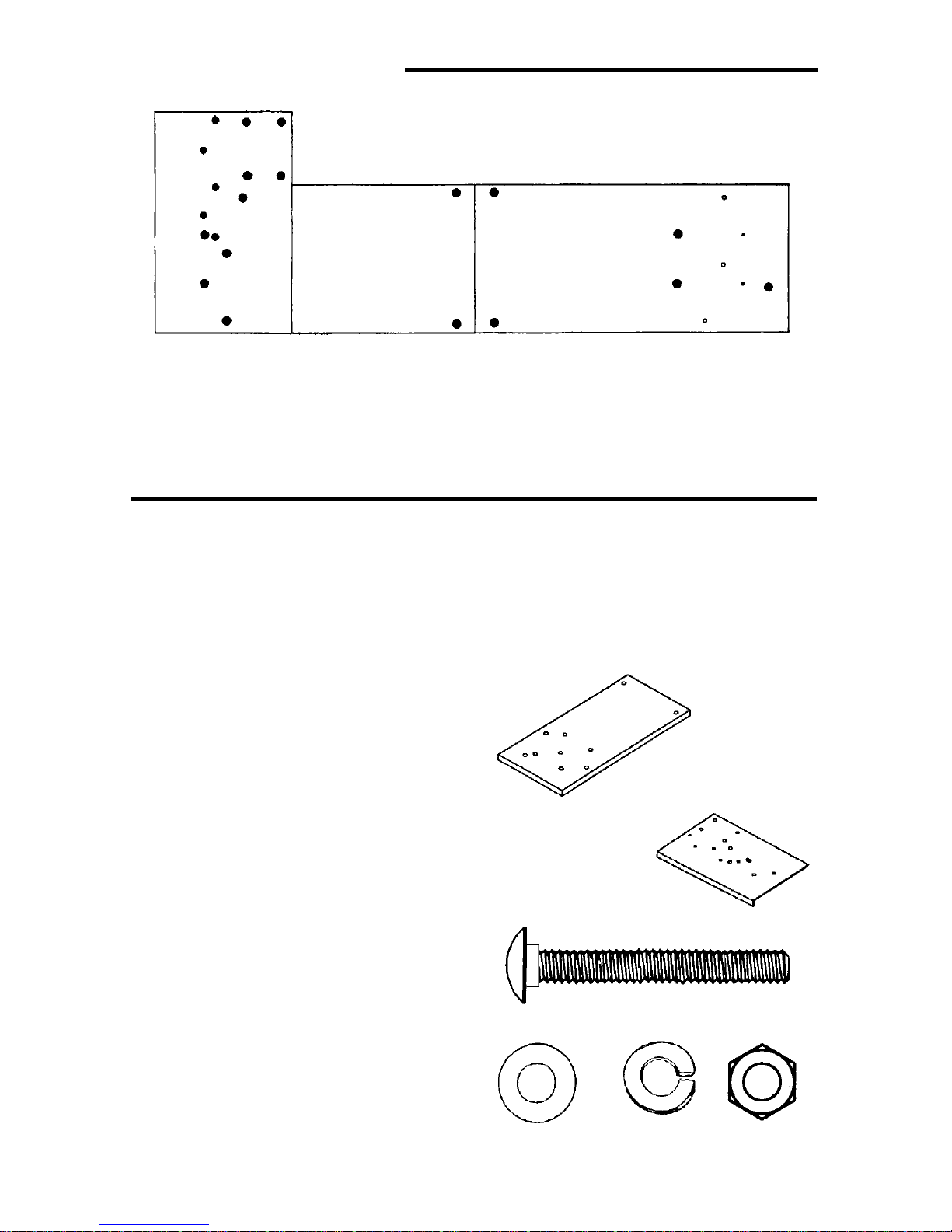
M Bracket Plate...................................1
N Particle Board Table To p .................2
O Plate-Support (Steel).......................1
P Leg..................................................4
Q End Stiffener................................ ...2
R Side Stiffener...................................2
S Operator’s Manual ..........................1
T 6" Face Plate................................ ...1
U L ive Center......................................1
Framing
Square
9
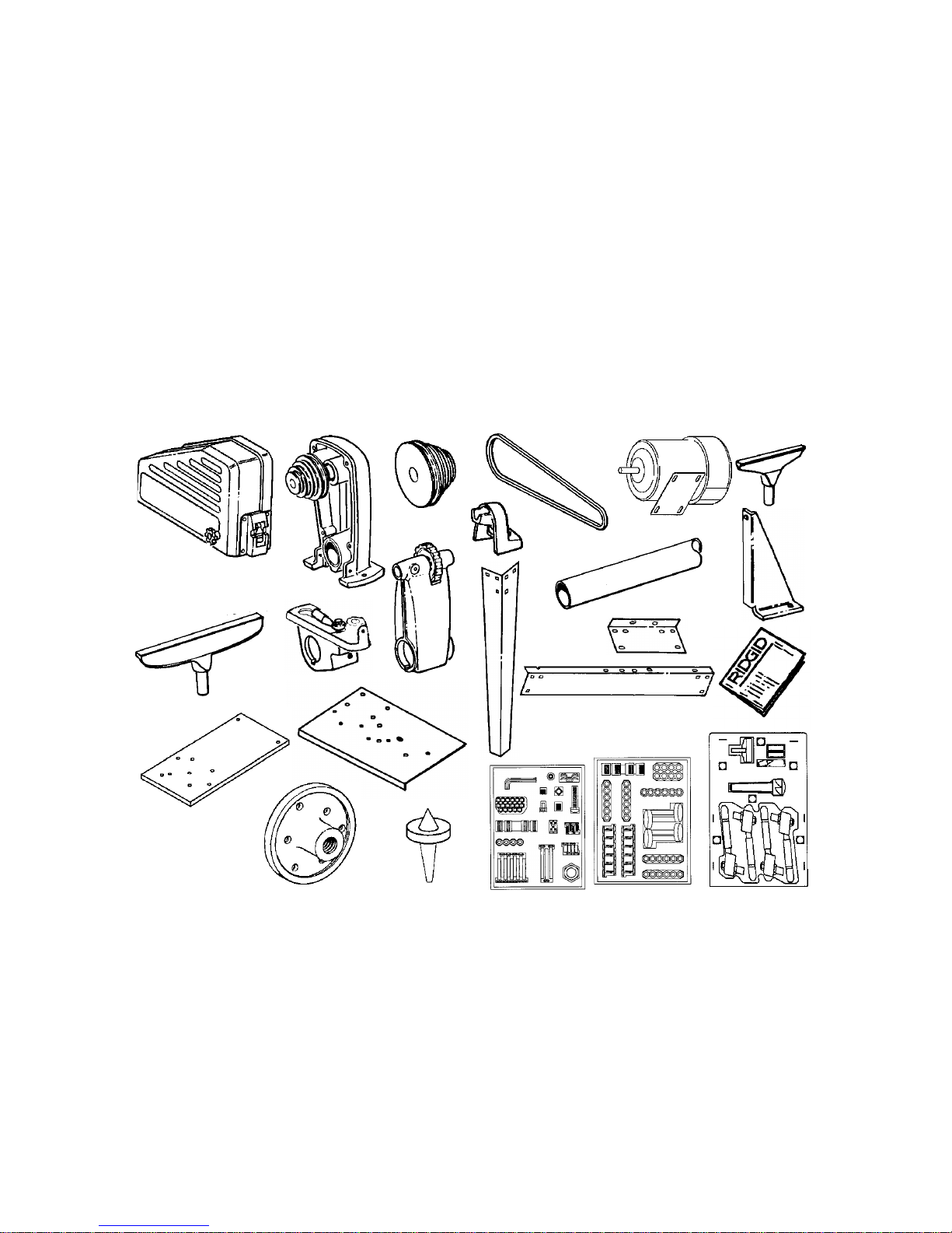
V Loose Parts Package
D
E
A
(Containing the following items):
Bolt, Carriage M6 x 1.0-45 ..............9
Bolt, Carriage M6 x 1.0-65 ..............3
Bolt, Carriage M6 x 1.0-16 ..............4
Lockwasher, Ext. 5mm ....................4
Item Description Qty.
Lockwasher, 6mm .........................17
Nut, Hex M6 x 1.0..........................17
Nut, Sq. M8 x 1.25...........................1
Nut, Hex Heavy 3/4-16....................1
Screw, Pan Hd. M8 x 1.25-45..........1
Screw, Pan Hd. M5 x 0.8-12............4
Screw, Hex Head M10 x 1.5-30.......1
Washer, 6.5 x 19 x 1.6...................17
Wrench, Hex “L” 4mm .....................1
Screw Soc. Set M8 x 1.25-8............1
Screw , Pan Head M4 x 0.7-6...........5
B
C
J
Screw, Hex Head M6 x 1.0-12........1
Cord Clamp.....................................2
W Loose Parts Package
(Containing the f ollowing items):
Bolt, Carriage M8 x 1.25-16..........24
Nut, Hex M8 x 1.25.......................24
Washer M8 x 16 x 1.6...................24
Lockwasher, 8mm.........................24
Foot Leveling 3/8" ...........................4
Nut Hex Jam 3/8-16........................8
X Loose Parts Package
(Containing the f ollowing items):
Spur Center.....................................1
Point Center................................... 1
Switch Key ......................................1
Lever, Assembly..............................4
Shoe, Lock......................................2
L
H
P
K
M
G
F
Q
R
S
O
N
W
V
X
T
U
10
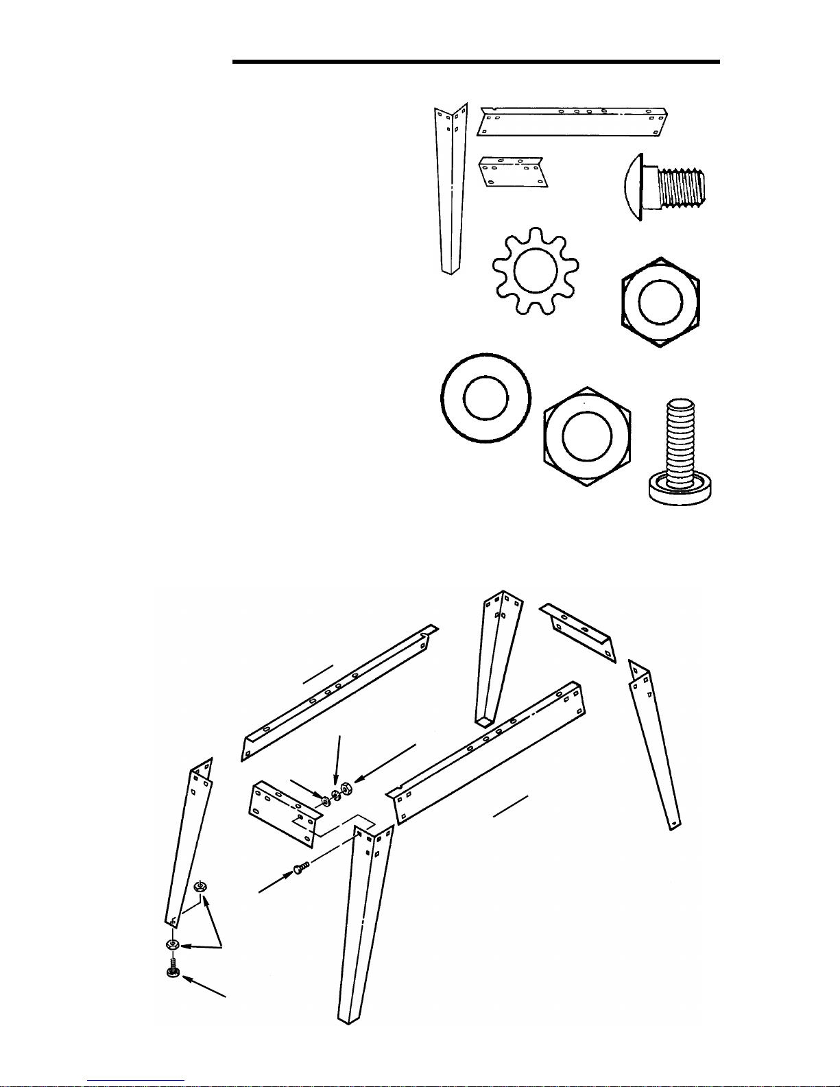
Assembly
lt
Assembling Steel Legset
1. Find the following legset pieces:
4 Legs
2 Side Stiffeners
2 End Stiffeners
2. From the loose parts pac ka ge fin d the
following items:
24 Carriage Bolts M8 x 1.25-16
24 Lockwashers M8 External Type
24 Hex Nuts,M8 x 1.25
24 Washer M8 x 16 x 1.6
8 Hex Nuts, 3/8-16
4 Leveling feet
3. Assemble the legset as shown. The
legs must be a ssembl ed on th e ou tside
of stiffeners and the side stiffener on
top of the end stiffene rs. Insert the truss
head screws through the holes in the
legs, then through the holes in the side
or end stiffeners.
4. Install washer and lockwasher. Screw
on the nuts finger tight.
5. Install leveling feet as shown:
Side Stiffener
End
Stiffener
Carriage Bo
M8 x 1.25-16
Leg
Lockwasher
M8 External
Hex Nut
M8 x 1.25
Washer
M8 x 16 x 1.6
Hex Nut 3/8-16
Leveling
Foot
M8x16x1.6
Washer
M8 x 1.25 x 16
Carriage Bolt
3/8-16 Hex Nut
Leveling Foot
r
a
e
R
M8
Lockwasher
M8 x 1.25
Hex Nut
11
t
n
o
r
F
Assembly (continued)
6
p
Holes Used for Mounting Boards and Wood Lathe to Leg Set
G
J
G
J
G
C
C
H
H
HH
F
E
E
A
A
A - Board/Side Support
B - Board/Side Support
C - Plate Support/Board/End Support
D - Board/End Support
E - Headstock/Plate Support/Board
Mounting Left Side Table Top
1. Find the following:
1 Particle Board Table Top
1 Plate Support (Steel)
2. From the loose parts pac ka ge fin d the
following:
4 M6 x 1.0-45 Carriage Bolts
4 M6 x 1.0 Hex Head Nuts
4 6.5 x 19 x 1.6 Flat Washers
4 6mm Lockwashers
3. Position the table top on the left side of
the assembled legset as shown
4. Front Side Stiffe ners
Face the front of the legset and count
over from the left one slot and on e hole.
Place a carriage bolt through the table
top (hole A) and the side stiffener. Fasten in place with a washer, lockwasher
and nut. Finger tighten only.
5. Rear Side Stiffener
Face the r ear of the l egset and count
over from the right two holes. Place a
carriage bolt through the table top (hole
A) and the side stiffener. Fasten in
place with a washer, lockwasher and
nut. Finger tighten only.
6. Locate the two holes marked C in the
steel plate support. Place bolts;
- through these holes
B
D
D
K
B
F - Bracket Plate/Plate Support/Board/
Side Support
G - Belt Guard/Plate Support
H - Motor/Plate Support
J - Cord Clamps/Plate Support
K - Rear Foot/Board
- through the two holes marked C on
the table top
- and through the holes marked C in
the End Stiffener. Place a wa sher,
lockwasher and nut on these bolts.
Finger tighten only.
Particle Board Table To
Plate Support (Steel)
Carriage Bolt
M6 x 1.0-45
Flat Washer Nut Hex
.5 x 19 x 1.6 M6 x 1.0
Lockwasher
6mm
12
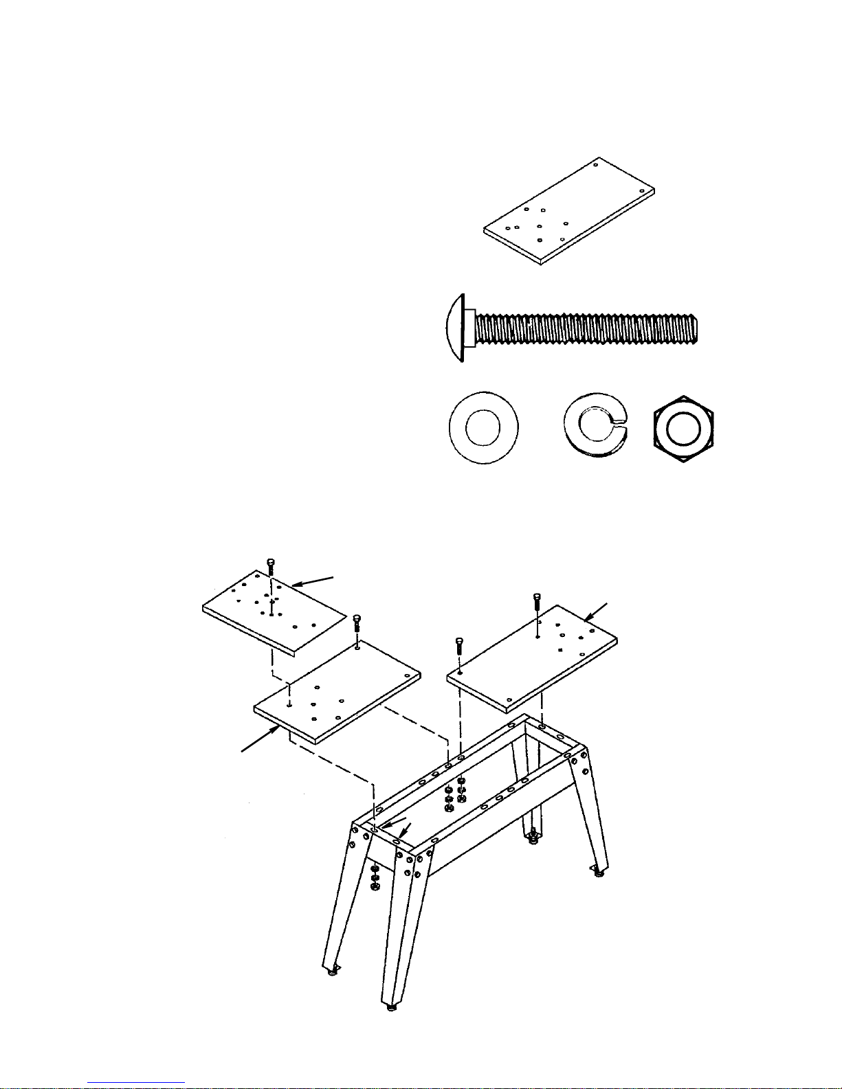
Mounting Right Side Table Top
x
0
1. Find the following:
1 Particle Board Table Top
2. From the loose parts pac ka ge fin d the
following:
4 M6 x 1.0-45 Carriage Bolts
4 M6 x 1.0 Hex Head Nuts
4 6.5 x 19 x 1.6 Flat Washers
4 6mm Lockwashers
3. The right side mounts similar to the left
except there is no steel suppo rt plate .
4. Place carriage bolts, through the table
top holes B and D as shown. Align the
right side table top with the left side
table top so that the two ha lves join end
to end. Fasten in place with a washer,
lockwasher and nut.
5. Securely tighten all nuts and bolts.
6. Adjust leveling feet as follows:
a. Move legset to desired location.
b. Wi th a 14mm wrench l oosen bo ttom
nut.
c. Back off top nut by hand.
d. Rai se or lower foot by adjust ing bot-
tom nut using 14mm wrench.
e. Snug top nut against inside of leg by
hand.
f. Tighten all four bottom nuts using
14mm wrench.
Particle Board Table Top
Carriage Bolt
M6 x 1.0-45
Flat Washer Nut He
6.5 x 19 x 1.6 M6 x 1.
Lockwasher
6mm
Left Side
Table Top
C
C
C
Motor Mounting Plate
A
A
C
C
Right Side
Table Top
D
D
B
B
13
Assembly (continued)
t
r
6
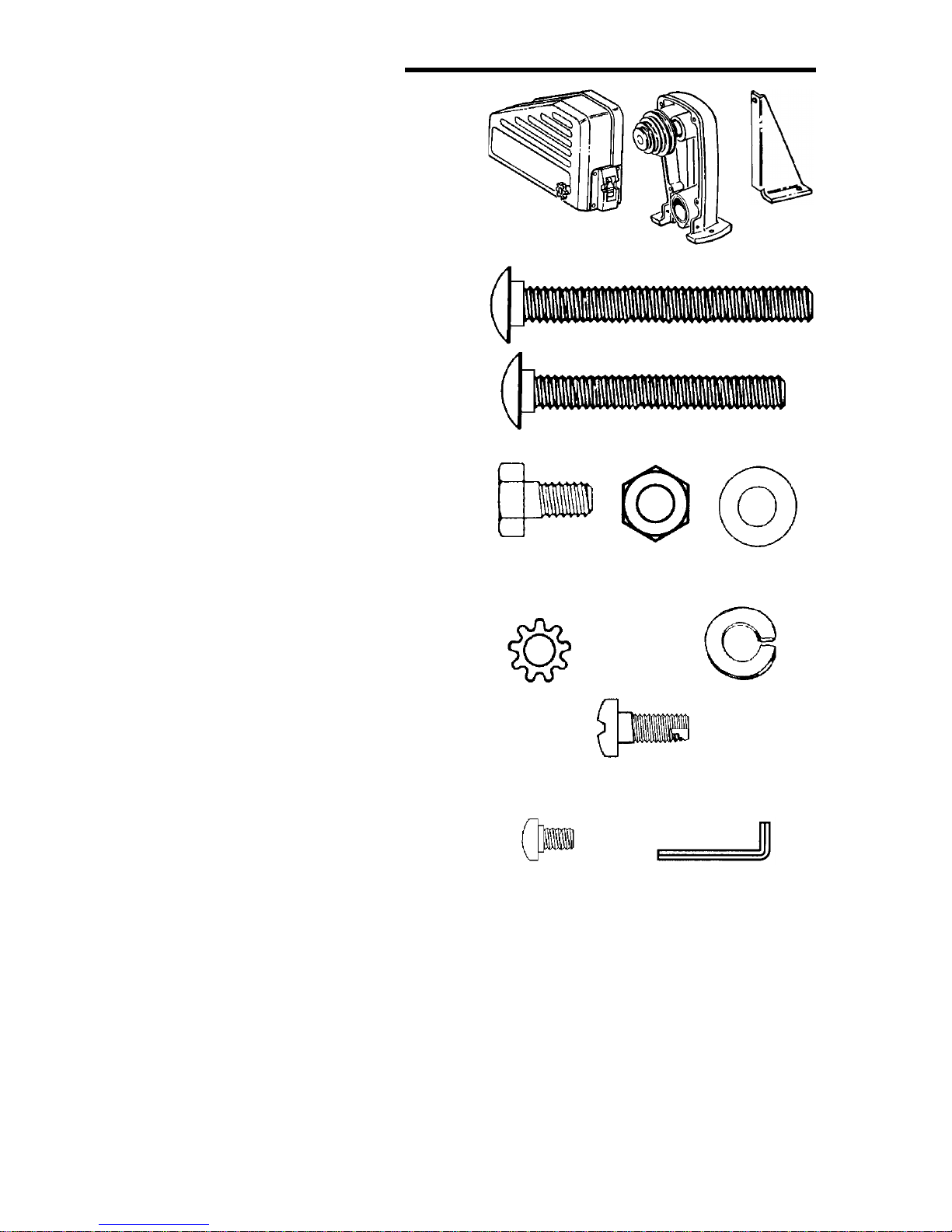
Mounting Headstock
1.Find the following:
1 Belt Guard Assembly
1 Headstock Assembly
1 Plate Bracket
2.From the loose parts pac kage find the
following:
2 M6 x 1.0-65 Carriage Bolts
1 M6 x 1.0-45 Carriage Bolt
1 M6 x 1.0-12 Hex Head Screw
4 M6 x 1.0 Hex Nuts
4 6.5 x 19 x 1.6 Fl at Washers
4 6mm Lockwashers
4 M5 x 0.8-12 Pan Head Screws
4 5mm Lockwasher
3 M4 x 0.7-6 Screw
1 Hex “L” Wrench 4mm
Belt Guard
Assembly
Bracke
Plate
Headstock
Assembly
Carriage Bolt
M6 x 1.0-65
Carriage Bolt
M6 x 1.0-45
3.Remove the headstock pulley usin g
the 4mm hex “L” wrench.
4.Find four pan head thread cutting
screws and four lockwashers from
among the lo ose p arts. Att ach th e belt
guard to the he ads to ck as se mbly with
these screws and lockwashers. The
arrows in this illustration show the
location of the screws.
5.Locate the two holes on the left table
top Labeled E (from page 12). Position the headstock assem bl y so the
mounting holes line-up with the holes
in the table board. Place a M6 x 1.065 carriage bolt, through these holes.
Fasten in place with a washer, lockwasher and nut.
6.Place the bracket plate next to the
headstock as shown. Attach the
bracket plate to the back of the belt
guard assembly with a M6 x 1.0-12
screw, washer, lockwasher and nut.
Hex Head
Screw
M6 x 1.0-12
Lockwasher
6mm
Pan Head Thread Cutting
Screw M5 x 0.8 x 12
Pan Screw
M4 x 0.7-6
Nut Hex
M6 x 1.0
Hex “L” Wrench 4mm
Flat Washe
6.5 x 19 x 1.
Lockwasher
5mm
14
7.Locate Hole F on the left table board.
lt
6
y
Attach the bracket plate to the table
top through Hole F. Use an M6 x 1.045 carriage bolt, washer, lockwasher
and nut. Finger tighten.
8.Locate the three holes Labeled G on
the lower edge of the be lt guard pla te.
Place a M4 x 0.7-6 screw through
each of these holes and into the
tapped holes in the plate support.
9.Replace pulley on headstock tightening with 4mm hex “L” wrench.
10.Securely tighten all nuts and bolts.
G
G
G
M6 x 1.0-12
Hex Head Screw
M6 x 1.0-45
Carriage Bolt
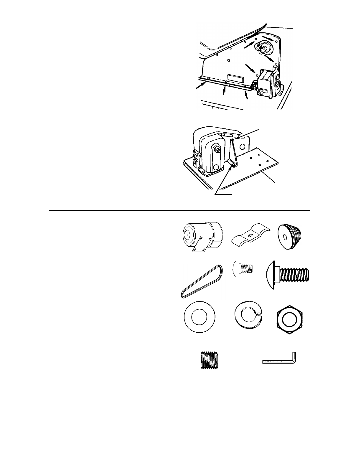
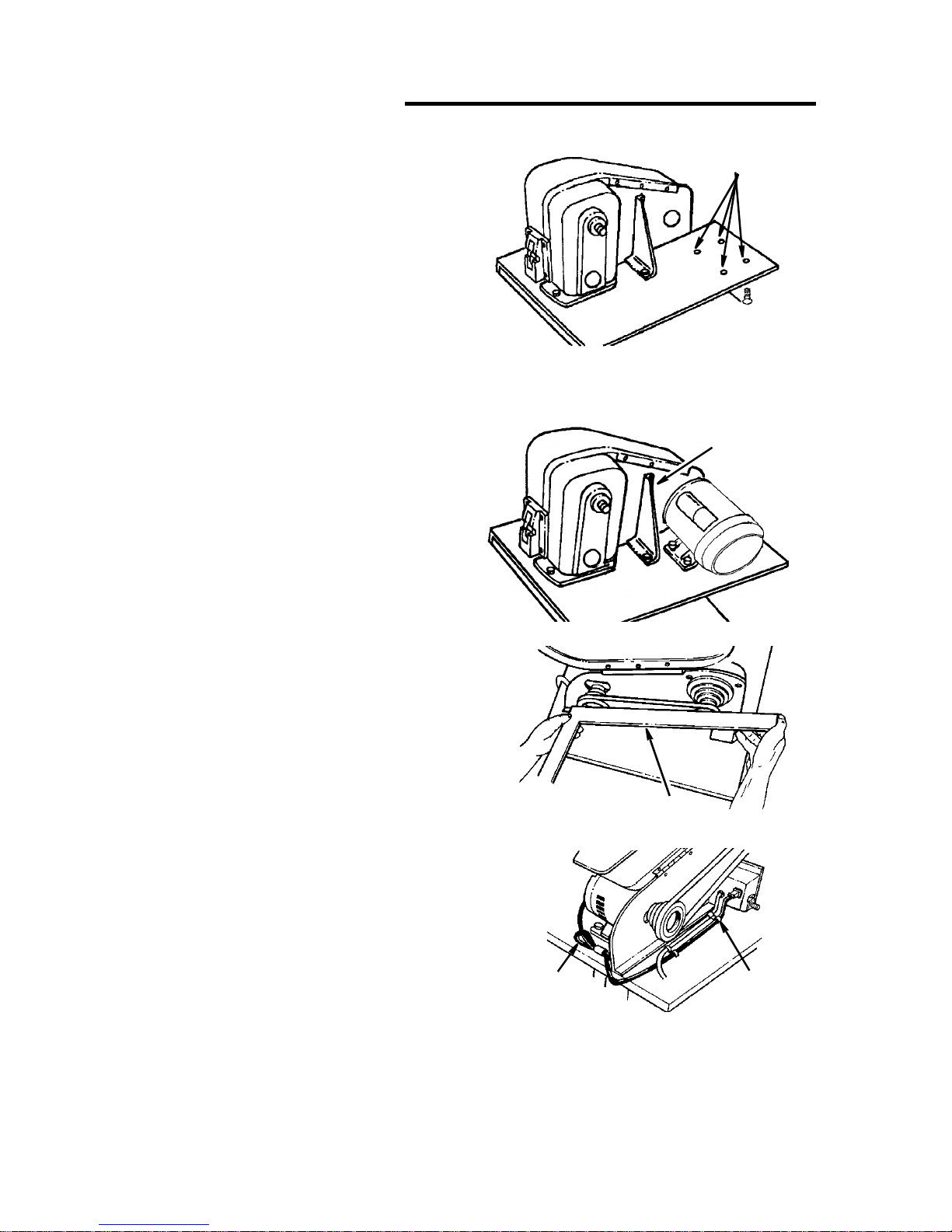
Mounting the Motor
1. Find the following:
1Motor
1 Motor Pulley
2 Cord Clamps
1V-Belt
2. From the loose parts pac ka ge fin d the
following:
2 M4 x 0.7-6 Pan Head Screws
4 M6 x 1.0-16 Carriage Bolts
4 6.5 x 19 x 1.6 Flat Washers
4 6mm Lockwashers
4 M6 x 1.0 Hex Nuts
1 M8 x 1.25-8 Socket Set Screw
1 4mm Hex “L” Wrench
Motor
Cord Clamp
Pan Screw
M4 x 0.7-6
V-Belt
Washer
Lockwasher
.5 x 19 x 1.6
Socket Set Screw
M8 x 1.25-8
6mm
Motor Pulle
Carriage Bo
M6 x 1.0-16
Hex Nut
M6 x 1.0
4mm Hex “L”
Wrench
15
Assembly (continued)
Holes for Mounting
t
3. Locate the fou r hol es Lab ele d H on th e
plate support.
4. Place the motor over these holes with
the motor shaft extending through the
belt guard plate. Secure in place with
carriage bolts, washers, lockwashers
and nuts.
5. Plug motor cord into outlet on back of
switch box. Do No t plug motor co rd into
power source outlet.
6. Route the motor cord and power cord
along side the headstock as shown.
Secure the motor cord and power cord
with two cord cl amps and an M4 x 0.7-6
pan head screw into the tapped holes
Labeled J in the motor mounti ng pla te.
7. Place the motor pulley on the motor
shaft so that the small diameter is
approximately 1/16" away from the
motor. Tighten the setscrew with the
4mm Hex “L” wrench securely against
the flat spot on the motor shaft.
8. Place the belt on the pulleys and slide
the motor toward the rear of work bench
until all the slack is removed from the
belt. Tighten only two of the motor
mounting bolts at this time.
NOTE: 1/2 inch d efl ection of belt un der
moderate pressure applied between
the two pulleys is adequate tension.
9. Place a strai ghtedge su ch as a piece of
wood, metal or framing square across
the pulleys to s ee if th ey are i n line wi th
each other. If they are, tighten the other
two motor mounting bolts. If they are
not in line, loosen the two motor bolts
and move the motor sideways unti l pulleys are in line. Tighten the bolts.
NOTE: Changing speeds is accomplished by repositioning the V-Belt on
the pulleys (see Changing Speeds”
section). There needs to be sufficient
slack in the V-belt to allow for this.
Install Carriage Bolts
from the Bottom Up
Straightedge
Motor
Cord
Motor (H)
Plate Bracke
Cord
Clamps
16
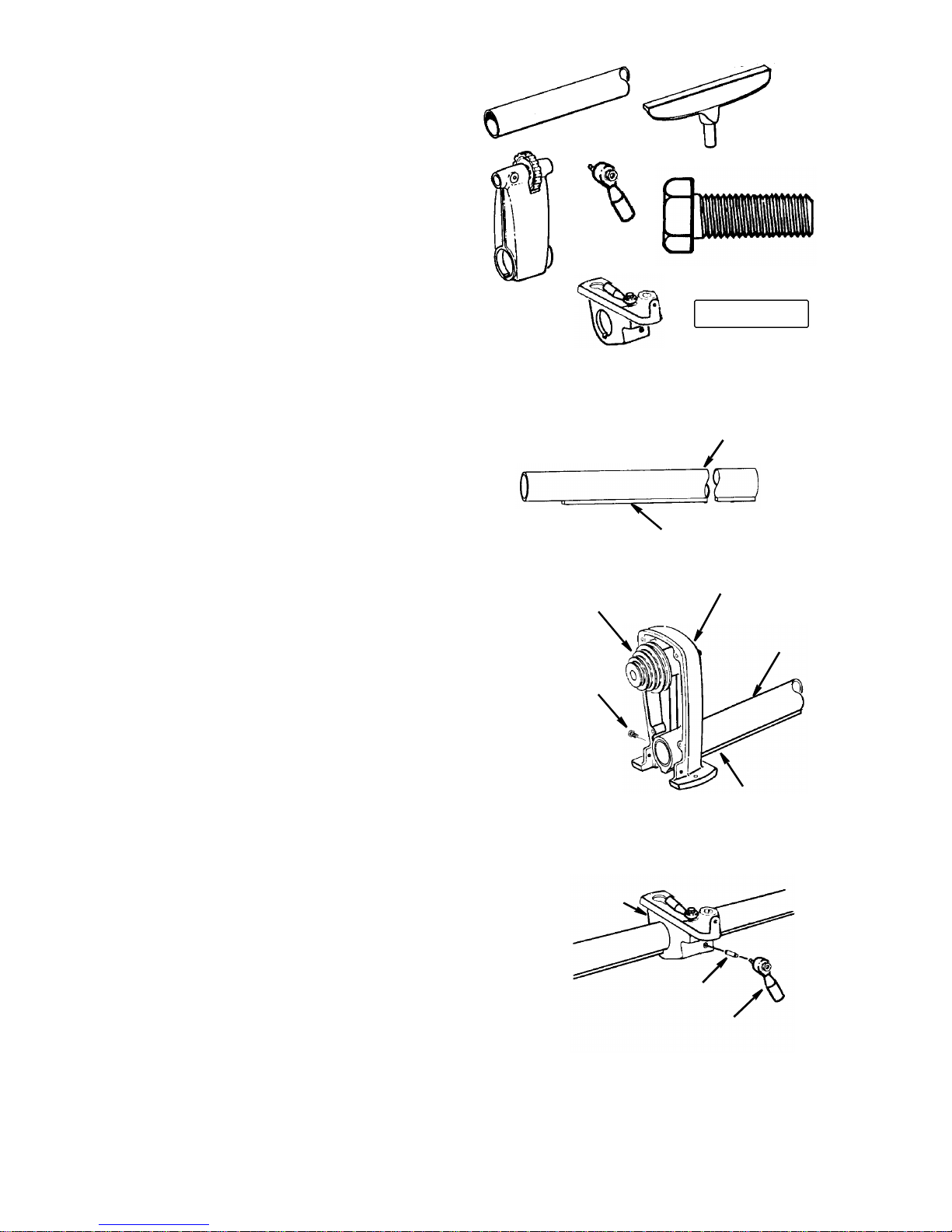
Headstock, Tailstock, and Tool
l
Tube Assembly
Headstock Spindle
H
Rest Assembly
1. Find the following:
1Tube
1 Large Tool Rest
1Tailstock
2Lever Assembly
1 Hex Head Screw M10 x 1.5-30
1 Tool Rest Holder/Clamp Support
Assembly
2 Brass Shoe Locks
2. Place the tube assembly on your workbench as shown. Always keep the
squared key section straight down.
Tube
Tailstock
Tool Rest Holder
Large Too
Rest
Lever
Assembly
Hex Hd Screw
M10 x 1.5-30
Brass Shoe
Lock
Clamp Support
Assembly
3. Slide th e tube into the he adsto ck un til it
stops against the squared key section.
Insert hex head screw and tighten
securely.
4. Slide the t ool re st holder /clam p support
assembly onto the middle of the tube.
Assemble lever assembly as shown.
NOTE: Make sure to insert brass shoe
lock before installing lever assembly.
Spindle Pulley
Hex Head
Locking Screw
in Rear of
Headstock
Clamp Support
eadstock
End
Squared Key Section
Tube
Squared Key
Section
Brass Shoe
Lock
Lever
Assembly
17
 Loading...