

RIDGID WL1200 Owner's Manual

OWNER’S MANUAL
For Your Safety:
Read all instructions carefully
Save this manual for future reference
Part No. SP6169 PrintedinU.S.A.
WL1200
12 INCH
WOOD TURNING LATHE

2
Table of Contents
Table of Contents ........................................................ 2
Safety Instructions For Wood Turning Lathe ............... 3
Safety Signal Words ................................................. 3
Before Using the Lathe ............................................. 3
When Installing Or Moving the Lathe ........................ 3
Before Each Use ....................................................... 3
To Reduce the Risk of Injury From Jams, Slips Or
Thrown Pieces (Kickbacks Or Throwbacks) ............ 4
Plan Ahead To Protect Your Eyes, H ands, Face and
Ears ......................................................................... 4
Inspect Your Workpiece ............................................ 4
Whenever Lathe Is Running ..................................... 5
Before Leaving the Lathe .......................................... 5
Motor Specifications and Electrical Requirements ...... 5
Connecting to Power Source Outlet .......................... 5
Wire Sizes .................................................................6
Check Motor Ro tation ............................................... 6
Unpacking and Checking Contents ............................. 6
Tools Needed ............................................................6
Unpacking .................................................................6
List of L oose Parts .................................................... 7
Assembly ..................................................................... 8
Assembling Steel Legset .......................................... 8
Holes Used for Mounting Boards and Wood Lathe to
Leg Set .................................................................... 9
Mounting Left Side Table Top ................................... 9
Mounting Right Side T able Top .............................. 10
Mounting Headstock ............................................... 11
Mounting the Motor .................................................12
Headstock,Tailstock, and Tool Rest Assembly ....... 13
Mounting Rear Foot ................................................ 14
Spur and Cup Ce nter Installation ............................ 15
Check Spindle Rotation .......................................... 16
AligningCenters ...................................................... 16
Adjusting Tailstock .................................................. 16
Getting To K now Your Wo od Lathe ........................... 17
On-off Switch .......................................................... 18
Speed Chart .............................................................18
Basic Lathe Operations ..............................................19
Changing Speeds ....................................................19
Spindle Turning ........................................................20
Indexing ...................................................................21
How To Use Your RIDGID Wood Lathe .....................22
Woodworking Chisels and How to Use Them .........22
The Six Commonly Used Chisel T ypes ...................22
Selection Of Chisels ................................................ 22
Theory Of Turning ....................................................22
Using The Gouge .....................................................24
Using The Skew .......................................................24
Using The Parting Tool ............................................25
Using The Scraping Chisels .................................... 25
Using Shaper Or Moulding Knives ...........................25
Using Wood Rasps And Files ..................................26
Hand Positions .........................................................26
Making Standard Cuts .............................................27
How To Handle Spindle Turnings ............................30
Duplicate Turnings ...................................................31
Long Spindles ..........................................................32
Use Of B ac k sticks (Not provided) . ...........................32
Miscellaneous Operations .......................................33
Faceplate & Chuck Turnings ................................... 33
How To Make Fancy Faceplate Turni ngs ................34
How to Turn Plastics ................................................38
Sanding, Buffing And Polishing ...............................39
Wiring Diagram ...........................................................41
Maintenance ...............................................................41
Maintenance ............................................................41
Lubrication ..................................................... ..........41
Troubleshooting ..........................................................42
General ....................................................................42
Motor ........................................................................ 43
Motor Connections .....................................................44
Repair Parts ...............................................................45
Notes ..........................................................................50

3
Safety Instructions For Wood Turning Lathe
Safety is a combination of common sense, staying alert and knowing how your lathe work s. Read this manual to understand this tool.
Safety Signal Words
DANGER: means if the safety information is not followed
someone will be seriously injured or killed.
WARNING: means if the safety information is not followed
someone could be seriously injured or killed.
CAUTION: means if the safety information is not followed
someone may be injured.
Before Using the Lathe
WARNING: S ome dust created by power sand ing,
sawing, grinding, drilling, and other construction
activities contains chemicals known (to the State
of California) to cause cancer, birth defects or
other reproducti ve harm. Some examples of these
chemicals are:
• Lead from lead-bases paints,
• Crystalline silica from bricks and c ement and
other masonry products, and
• Arsenic and chromium from chemically-treated
lumber.
Your risk from these exposures varies, depending
on how often you do this type of work. To reduce
your exposure to these chemicals: work in a well
ventilated area, and work with approved safety
equipment, s uch as those dust masks that ar e specially desig ned to filter out microscopic particles.
WARNING: To reduce the risk of mistakes that
could c ause se rio us, permanent injury,do not plug
the lathe in until the following steps have been satisfactorily comp leted.
Know and Understand the Lathe
• Completely assemble and align lathe.
• Learn the use and f unc tion of the ON-OFF switch.
• Review and understand all safety instructions and
operating procedures in this manual.
• Review the maintenance methods for t his lathe.
• Find and read the warning label found on the lathe
(shown below).
When Installing Or Moving the Lathe
Reduce the Risk of Dangerous Environment.
• Use the lathe in a dry, indoor place protected from rain.
• Keep work area well lighted.
To reduce the risk of injury from unexpected lathe
movement.
• The lathe and motor must be bolted down to a stand or
workbench for stability.
• To reduce the r isk of inj ury from electrical sho ck, make
sure your fingers do not touch the plug’s metal prongs
when plugging in or unplugging the lathe.
• Turn off a nd unplug the lathe before moving it to a new
area. To reduce the risk of back injur y, get help when
you need to lift o r move the lathe.
• Never Stand On Tool. Serious injury could occur if the
tool tips or you accidentally hit the cutter h ead. Do not
store anything above or near the tool where anyo ne
might stand on the tool to reach them.
Before Each Use
Inspect your lathe.
• To reduce the risk of injury from accidental starting, turn
the switch off, unplug the lathe, and remove the switch
key before changing the speeds, changing the setup, or
adjusting anything.
• Check for alignment of moving parts, binding of moving
parts, breakage of parts, unit stability, and any other conditions that may affect the way the lathe works.
• If any part is miss ing, bent or broken in any way, or any
electrical part does not work properly, turn the lathe off
and unplug the lathe.
• Replace damaged, missing or failed parts before using
the lathe again.
• Keep l athe interior free of wood chips a nd dust buildup
around motor and switch box.
• Keep turning tools sharp. Dull or nicked tools tend to
dig in the wood, causing the tool or workpiece to be
thrown.
• To reduce the risk of injury from unsafe accessories,
use only recommended accessories.

4
Safety Instructions For Wood Turning Lathe (continued)
Use Recommended Accessories.
• To avoid injury from uns afe accessories, us e only recommended accessor ies.
• Consult the owners manual for recommended accessories.
• Follow the instructions that accompany the accessories.
WARNING: Use only accessories recommended for
this lathe. (Using other accessories may be dangerous.)
To Reduce the Risk of Injury From Jams, Slips Or Thrown Pieces (Kickbacks Or Throwbacks)
When turning between centers or on the faceplate:
- A lways rough-out "out of round" workpieces at slow
speed.
- Running the lathe too fast, so that it vibrates, could
cause the workpiece to be t hrown from the lathe... or
the turning tool to be jerked from your hands.
Always revolv e the workpiece by hand before turning on
the motor. If the workpiec e strikes th e tool rest, it could
split and be thrown out of the lathe.
Do not allow the turning tool to "bite" into the workpiece
which could result in splitting of the workpiece or the workpiece being thrown from the lathe.
- A lways position the tool rest above the centerline of
the lathe for spindle turning.
- Do not apply the turning tool to the workpiece below
the level of the tool rest.
Do not run the lathe in the wrong direction. This could
cause the turning tool to be t hrown from y our hands. The
lathe m ust r un in a direction so that the t op of the workpiece turns toward you.
Before attaching a workpiece to the faceplate:
- A lways "rough it out" to as "true round" as possible.
This will minimize vibration while turning.
- A lways fasten the workpiece securely to the faceplate.
- Failure to perform these set-up operations could
cause the workpiece to be thrown from the lathe.
Avoid awkward hand positions, where a sudden slip could
cause a hand to move into the workpiece.
Remove all loose knots before installing workpiece between c enters or on the faceplate.
Never leave t he lathe work area with the power on, before
the lathe has come to a complete stop , or without rem ov ing and storing the switch key.
Never operate the lathe with protective cover on t he unused shaft end of the motor removed.
Hang your turning tools on the wall toward the tailstock
end of t he lathe. Do not l ay them on the bench so that you
must reach over the revolving workpiece to select them.
Keep firm hold and control of the turning tool at all times.
Special caution must be exercised when knots or voids
are exposed to the turning tool.
Plan Ahead To Protect Your Eyes, Hands, Face and Ears
Reduce the Risk of Accidental Starting.
• Make sure switch is “OFF” before plugging lathe into a
power outlet.
Dress for sa fety.
• Any power tool can throw foreign objects into the eyes.
This can result in permanent eye damage. Always
wear safety goggles, not glasses complying with ANSI
Z87.1 (or in Canada CSA Z94.3-99) shown on package. Everyday eyeglasses have only impact resistant
lenses. They are not safety glasses. Safety goggles
are available at many local retail stores. Glasses or
goggles not in compliance with ANSI or CSA coul d
seriously hurt you when they break.
• For dusty operati ons, wear a dust mask a long with
safety goggles.
• Do not wear loose clothing, gloves, neckties or jewelry
(rings, wrist watches). They can get caught and draw
you into moving parts.
• Wear nonslip footwear.
• Tie back long hair.
• Roll long sleeves above the elbow.
• Noise levels vary widely. To reduce the risk of possible
hearing damage, wear ear plugs or muffs when using
lathe for hours at a time.
Inspect Your Workpiece
• Think Safety.
• Complete hand sanding of between-centers or faceplate mounted workpieces Before removing from the
lathe. Do not exceed t he speed used for the last cutting
operation performed on the workpiece, in accordance
with the s peed chart.
5
• Never attempt to remount a faceplate turning to the
faceplate for any reason. Never attempt to remount a
between-centers turning if the original centers in the
turning have been altered or removed. Be positive the
latheis set at the lowestspeed if remountingabetweencenters turning with non-alteredoriginalcenters.
• Use extra caution in mounting a between-centers or
spindle turning to the faceplate, or a faceplate turning
to between- centers, for subsequent operations. Be
positive the lathe is set at the lowest speed before
turning ON.
• Never mount a workpiece that contains any splits,
checks, or loose knots to a faceplate or between centers.
• Do not perform any operation when hand holding the
workpiece. Do not mount a rea mer, milling cutter, wire
wheel, buffing wheel, or a drill bit to the headstock
spindle.
Whenever Lathe Is Running
WARNING : Don't allow familiarity (gained from frequent use of your lathe) to cause a c areless mistake. Always remember that a careless fraction of
a second is enough to cause a severe injury.
• Before actually tur ning with the lathe, let it run for a
while. If it makes an unfamiliar noise or vibrates a lot,
stop immediately. Turn t he lathe off. Unplug th e lathe.
Do not res tart until finding and correcting the problem.
Keep Children Away.
• Keep all visitors a safe distance from the lathe.
• Make sure bystanders are clea r of the lath e and workpiece.
Don’t Force Tool.
• Feed th e tool into the wor k piece o nly fast enough to let
the t ool c ut without bogging down or b indin g.
Before fr eeing jammed material.
•Turnswitch“OFF”.
• Wait for all moving part s to stop.
• Unplug the lathe.
Before Leaving the Lathe
• Turn the lathe off.
• Wait for lathe to come to a complete stop.
• Unplug the lathe.
• Make w orkshop child-proof. Lock the s hop. Disconnect
master switches. Remove the yellow switch key. Store
it away from children and ot hers not qualified to use
the t ool.
Motor Specifications and Electrical Requirements
This Lathe is designed to use a 1725 RPM motor only. Do
not use any motor that runs faster than 1725 RPM. It is
wired for ope ration on 110-120 volts, 60 Hz., alternating
current.
CAUTION: Do not use blower or washing machine
motors or any motor with an automatic res et overload protector as their use may be hazardo us.
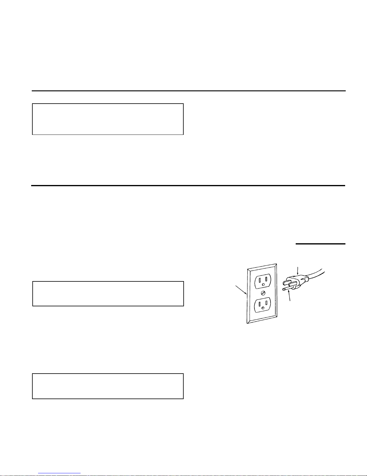
Connecting to Power Source Outlet
Thismachine must be grounded while in use to protect the
operator from electric shock.
Plug power cord into a 110-120V properly grounded type
outlet protected by a 15-amp. dual element time delay or
Circuit-Saver f us e or circuit breaker.
If you are not s ure that your outlet is properly grounded,
have it checked by a qualified electrician.
WARNING: Do not permit fingers to touch the terminals of plugs when installing or removing the plug
to or fr om the outlet.
If power cord is worn or cu t, or damaged in any way, have
it repl ac ed imm ediately.
If your unit is for use on less than 150 volts it has a plug
that looks like below.
This power tool is equipped with a 3-conductor cord a nd
grounding type plug which has a grounding prong,
approved by Underwriters' L aboratories. The ground conductor has a green jacket and is attached to the tool
housing at one end and to the ground prong in the attachment plug at the other end.
This plug requires a mating 3-conductor grounded type
outlet as shown.
If the outlet you are planning to use for this power tool is
of the two prong type Do Not Remove Or Alter The
Grounding Prong In Any Manner. Use an adapter as
shown and always connect t he grounding lug to k nown
ground.
It is recommended that you have a qualified electrician replace the two prong outlet with a properly grounded three
prong outlet.
Properly
Grounded
Outlet
3-Prong Pl ug
Grounding
Prong
6
Motor Specifications and Electrical Requirements (continued)
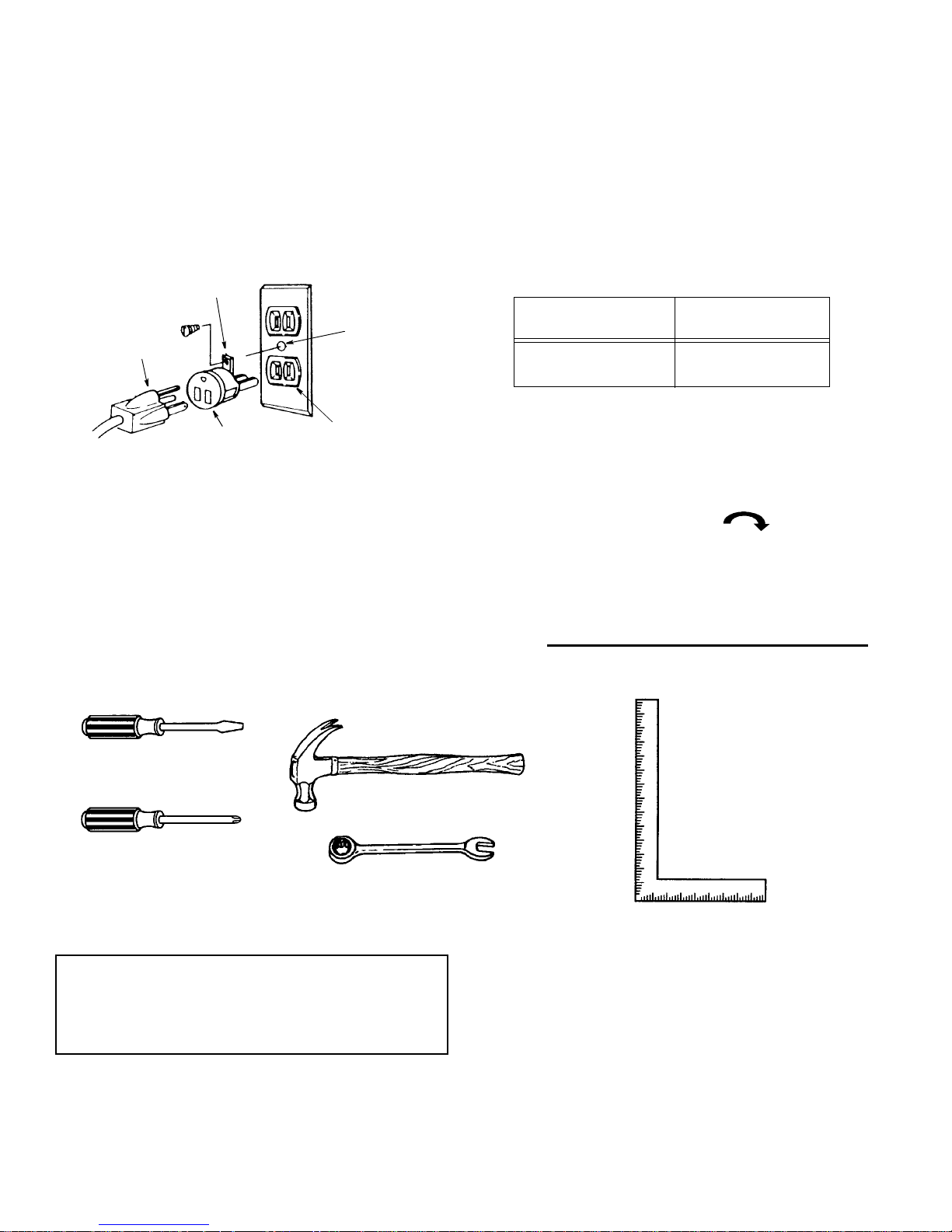
A temporary adapter as shown below is available for connecting plugs to 2-prong receptacles. The green grounding lug extending from the adapter must be c onnected to
a permanent ground such as to a properly grounded outlet
box.
A temporary adapter, as illustrated, is available for connecting plugs to 2-prong receptacles. The t emporary
adapter should b e used only until a properly grounded
outlet can be installed by a qualified electrician.
NOTE: The adapter illustrated is for use only if you already have a properly grounded 2-prong receptacle.
NOTE: In Canada the use of a temporary adapter is not
permitted by the Canadian Electrical Code.
Wire Sizes
NOTE: Make s ure the proper extension cord is used and
is i n g ood condition.
The us e of any extension cord will cause s ome loss of
power. To keep this to a minimum and to pre vent overheating and motor burn-out, use the table below to determine the minimum wire size (A.W.G.) ext ens ion cord. Use
only 3 wire extension cords which have 3-prong grounding type plugs and 3-pole receptacles which accept the
tool’s plug.
Check Motor Rotation
Place the m otor on your work bench or on the floor.
Standing clear of the motor shaft, plug the motor cord
into a properly grounded outlet. Notice the rotation of t he
shaft. As you look directly at the motor shaft it should be
turning in the clockwise direction. If the motor
shaft is turning clockwise, remove the plug from the
power outlet an d continue the assembly procedures. If
the motor is turning counterclockwise, remove t he plug
from the powe r outlet and co ntact 1 -800-4-RIDG ID.
Unpacking and Checking Contents
Tools Needed
Unpacking
WARNING: To reduce the risk of injury from unexpected starting or electrical sh ock, do not plug the
power cord into a source of power. This cord must
remain un plugged whenever you are working on
the wood lathe .
1. Unpack all t he p arts of your wood lathe and lay them
out in your work area so they can be recognized easily. Check all parts with the parts table and be careful
not t o lose any parts during assembly.
NOTE: Make certain all items are accounted for, before
discarding any packing mat erial.
Grounding Lug
3-Prong
Adapter
2-Prong
Outlet
Make sure this
Is Connected
Ground
Plug
Green
to a Known
Extension Cord
Length
Gauge
(A.W.G)
0-25 Ft.
26-50 Ft.
14
12
Medium Screwdriver
Phillips Screwdriver
Hammer
Framing Square
10mm Wrench
13mm Wrench
14mm Wrench
7
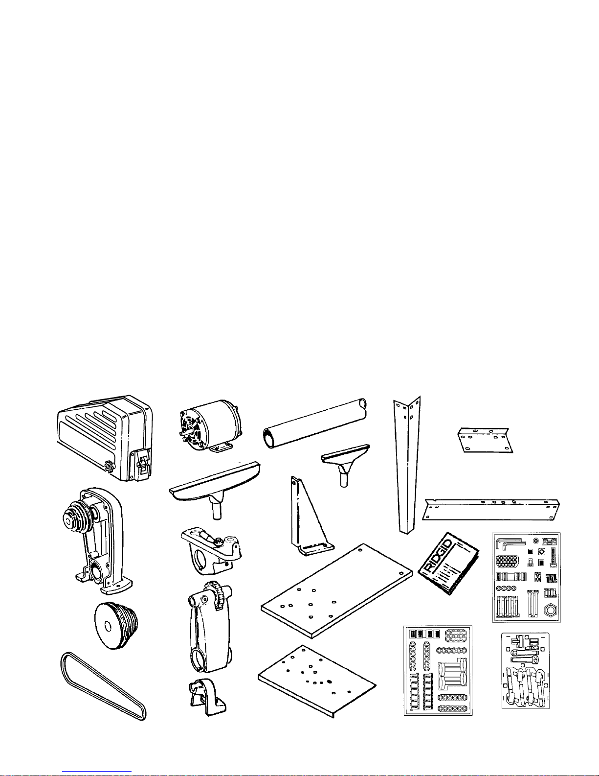
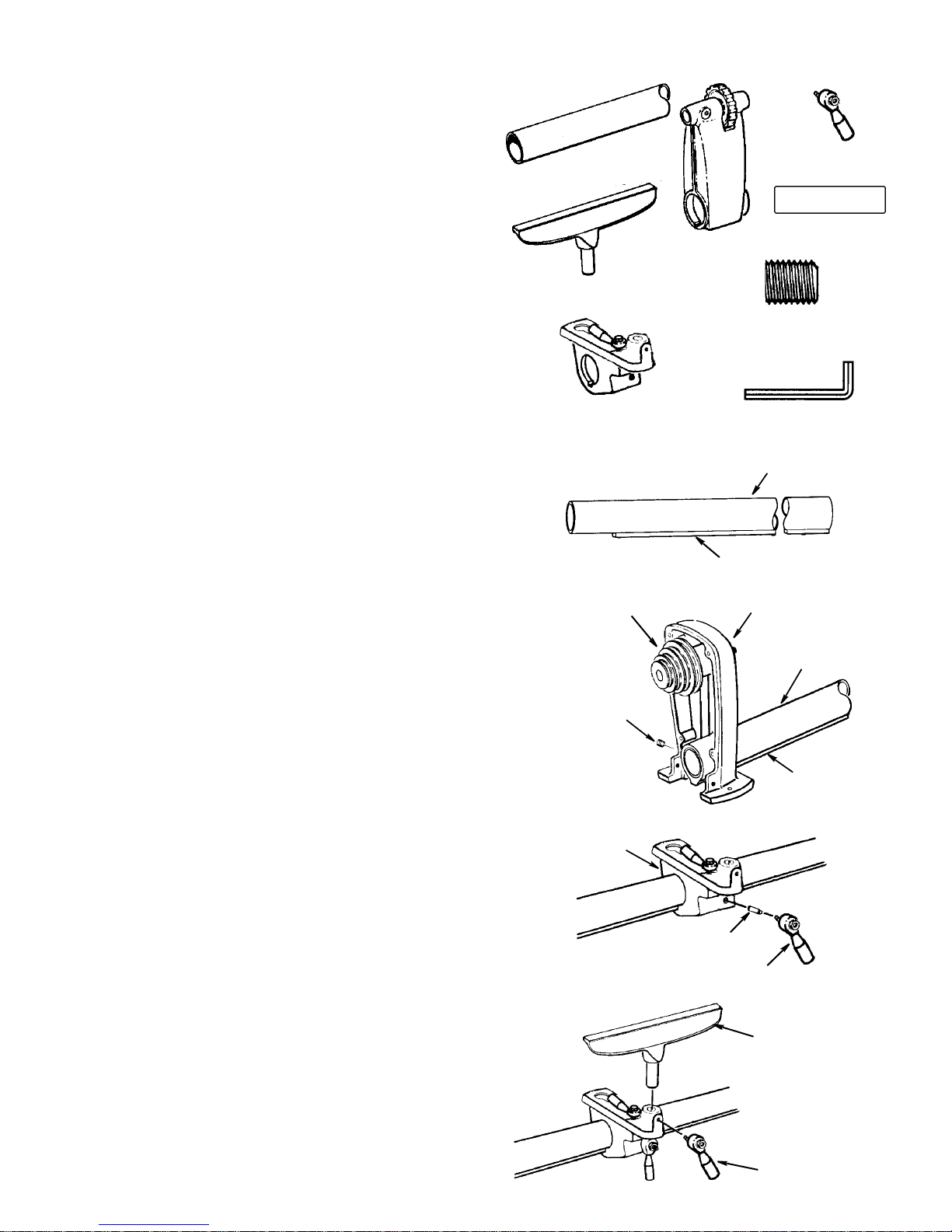
List of Loose Parts
Item Description Qty.
A Belt Guard Assembly......................................... 1
B Headstock ......................................................... 1
C Motor Pulley ......................................................1
D V-Belt................................................................. 1
E Motor................................................................. 1
F Large Tool Rest.................................................1
G Tool Rest Holder/Clamp Support Assembly...... 1
H Tailstock and Ra m ............................................. 1
J Rear Foot ..........................................................1
K Tube Or Bed ...................................................... 1
L Small Tool Rest ................................................. 1
M Bracket Plate..................................................... 1
N Particle Board Table Top ................................... 2
O Plate-Suppor t (Steel).........................................1
P Leg .................................................................... 4
Q End Stiffener...................................................... 2
R S ide Stiffener..................................................... 2
S Owners Manual .................................................1
T Loose Parts Package
(Containing the following items):
Bolt, Carriage M6 x 1.0-45 ................................9
Bolt, Carriage M6 x 1.0-65 ................................3
Bolt, Carriage M6 x 1.0-16 ................................4
Lockwasher, Ext. 5 mm ...................................... 4
Lockwasher, 6mm ...........................................17
Nut, Hex M6 x 1.0 ............................................ 17
Nut, Sq. M8 x 1.25............................................. 1
Nut, Hex Heavy 3/4-16......................................1
Item Description Qty.
Screw, Pan Hd. M8 x 1.25-45.............................1
Screw, Pan Hd. M5 x 0.8-12...............................4
Screw Socket Set M10 x 1.5-12.........................1
Washer, 6.5 x 19 x 1.6......................................17
Wrench, Hex “L” 4mm.........................................1
Wrench, Hex “L” 5mm.........................................1
Screw Soc. Set M8 x 1.25-8...............................1
Screw, Pan Head M4 x 0.7-6..............................2
Screw, Pan Head M4 x 0.7-4..............................3
Screw, Hex Head M6 x 1.0-12............................1
Cord Clamp........................................................2
U Loose Parts Package
(Containing the following items):
Bolt, Carriage M8 x 1.25-16.............................24
Nut, Hex M8 x 1.25 ..........................................24
Washer M8 x 16 x 1.6......................................24
Lockwasher, 8mm ............................................24
Foot Leveling 3/8"...............................................4
Nut Hex Jam 3/8-16 ...........................................8
V Loose Part s Package
(Containing the following items):
Spur Center........................................................1
Point Center ...................................................... 2
Cup Center.........................................................1
Switch Key..........................................................1
Lever, Assembly.................................................4
Shoe, Lock .........................................................2
A
B
C
D
E
F
H
J
M
O
P
Q
R
S
T
N
K
G
L
U
V
8
Assembly
Assembling Steel Legset
1. Find the following legset pieces:
4 Legs
2 Side Stiffeners
2 End Stiffeners
2. From the loose parts package find the following items:
24 Carri age Bolts M8 x 1.25-16
24 Lockwashers M8 External Type
24 Hex Nuts,M8 x 1.25
24 Washer M8 x 16 x 1.6
8 Hex Nuts, 3/8-16
4 Leveling feet
3. Assemble the legset as shown. The legs must be
assembled on the outside of stiffeners and the side
stiffener on top of the end stiffeners. Insert the t r us s
head screws through the holes in the legs, then
through the holes in the side or end stiffeners.
4. Install washer and lockwasher. Screw on the nuts fin-
ger tight.
5. Install leveling feet as shown:
Leg
Side Stiffener
End Stiffener
Lockwasher
M8 External
Hex Nut
Hex Nut 3/8-16
Leveling F oot
Washer
M8x1.25
M8x16x1.6
Carriage Bolt
M8 x 1.25-16
M8x1.25x16
3/8-16 Hex Nut
Leveling Foot
Carriage Bolt
M8x16x1.6
M8
Lockwasher
Washer
M8 x 1.25
Hex Nut
F
r
o
n
t
R
e
a
r
9
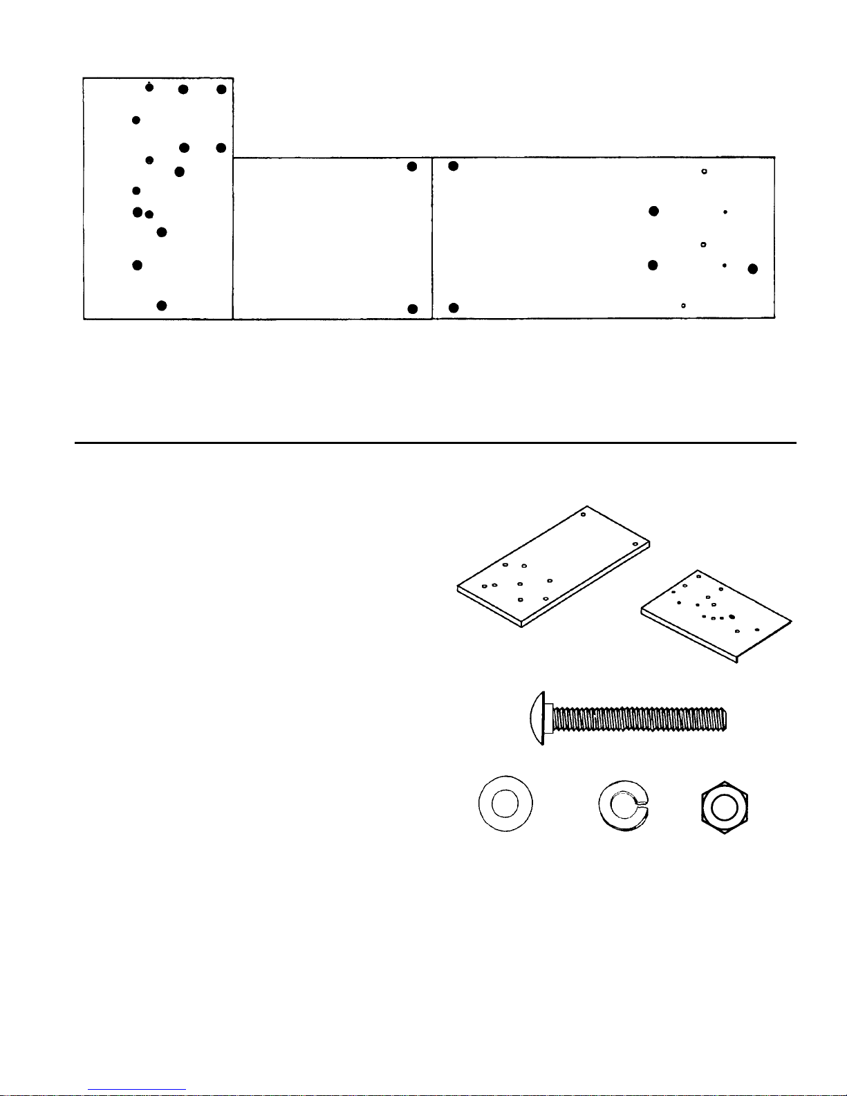
Holes Used for Mounting Boards and Wood Lathe to Leg Set
A - Board/Side Support
B - Board/Side Support
C - Plate Support/Board/End Support
D - Board/End Support
E - Headstock/Plate S upport/Board
F - Br ac k et Plate/Plate Support/Board/Side Support
G - B elt Gaurd/Plate S upport
H - Motor/Plate Support
J - Cord Clamps/Plate Support
K - Rear Foot /Board
A
B
C
D
E
G
F
H
H
H
A
C
H
B
D
E
G
J
J
K
G
Particle Board Table Top
Plate Support (Steel)
Carriage Bolt
M6x1.0-45
Flat Washer Nut Hex
6.5x19x1.6 M6x1.0
Lockwasher
6mm
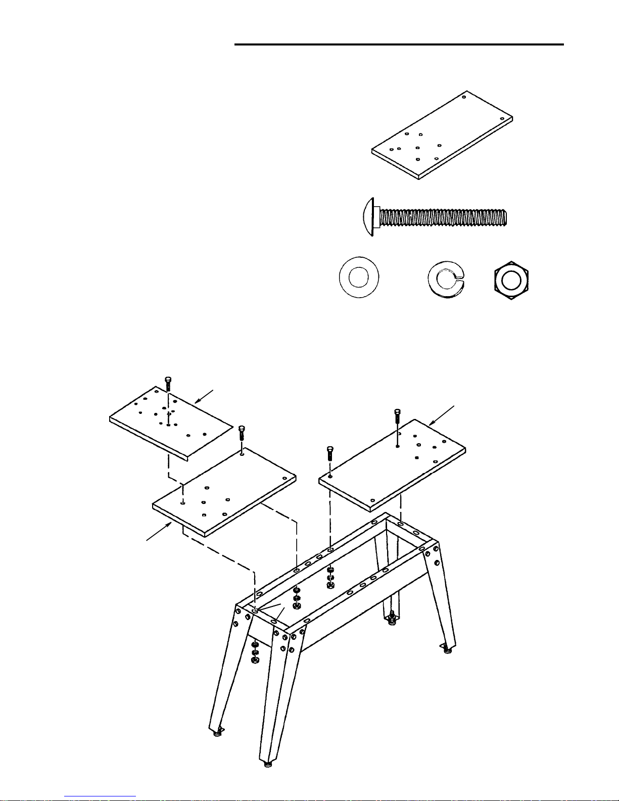
Mounting Left Side Table Top
1. Find the following:
1 Particle Board Table Top
1 Plate S upport (Steel)
2. From the loose parts package find the following:
4 M6 x 1.0-45 Carriage Bolts
4 M6x1.0HexHeadNuts
4 6.5 x 19 x 1.6 Flat Washers
4 6mmLockwashers
3. Position the table top on the left side of the assem bled
legset as shown
4. Front Side Stiffeners
Face the f ront of the legset and count over from the left
one slot and one hole. Place a carriage bolt through
the table top (hole A) and the side stiffener. Fasten in
place with a washer, lockwasher and nut. Finger
tighten only.
5. Rear Side Stiffener
Face the rear of the legset and count over from the
right two ho les. Place a carriage bolt th rough the table
top (hole A) and the side stiffener. Fasten in place with
a washer, lockwasher and nut. Finger tighten only.
6. Locate the two hol es marked C in the steel plate support. Place bolts;
- t hrough these holes
- through the two holes marked C on the ta ble top
- and through the holes marked C in the End St iffener.
Place a washer, lockwasher and nut on these bolts.
Finger tighten only.
10
Assembly (continued)
Mounting Right Side Table Top
1. Find the following:
1 Particle Board Table Top
2. From the loose parts package find the following:
4 M6 x 1.0-45 Carriage Bolts
4 M6x1.0HexHeadNuts
4 6.5 x 19 x 1.6 Flat Washers
4 6mmLockwashers
3. The right side mo unts similar to the left except there is
no steel support plate.
4. Place carriage bolts, through the table top holes B and
D as shown. Align the right side table top with the left
side table top so that the two halves join end to end.
Fasten in place with a washer, lockwasher and nut.
5. Securely tighten all nuts and bolts.
6. Adjust leveling feet as follows:
a. Move legset to desired location.
b. With a 14mm wrench l oos en bottom nut.
c. Back off top nut by hand.
d.Raise or lower foot by adjusting bottom nut using
14mm wrench.
e. Snug top nut against inside of leg by hand.
f. Tighten all four bottom nuts using 14mm wrench.
Particle Board Table Top
Carriage Bolt
M6x1.0-45
Flat Washer Nut Hex
6.5x19x1.6 M6x1.0
Lockwasher
6mm
Motor Mounting Plate
Left Side
Right Side
A
A
B
B
C
D
D
C
C
C
C
Table Top
Table Top
11
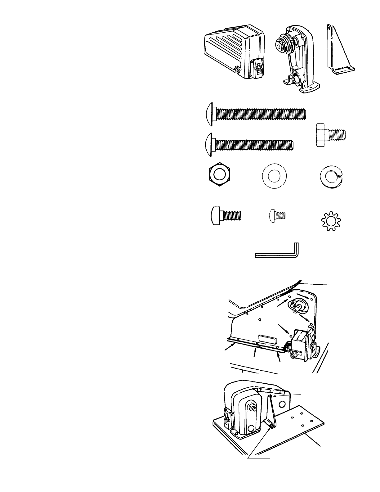
Mounting Headstock
1. Find the following:
1 Belt Guard Assembly
1 Headstock Assembly
1 Plate Bracket
2. From the loos e parts package find the following:
2 M6 x 1.0-65 Carriage Bolts
1 M6 x 1.0-45 Carriage Bolt
1 M6 x 1.0-12 Hex Head S c rew
4M6x1.0HexNuts
4 6.5x19x1.6FlatWashers
4 6mm Lockwashers
4 M5 x 0.8-12 Pan Head S crews
4 5mm Lockwasher
3 M4 x 0.7-6 Screw
1Hex“L”Wrench4mm
3. Remove the headstock pulley usi ng the 4mm hex “L”
wrench.
4. Find four pan head thread cutting screws and four
lockwashers from among the loose part s. Attach the
belt guard to the headstock assembly with these
screws and lockwashers. The arrows in this illustration show the location of the screws.
5. Locate the two holes o n the left table top Labeled E
(from page 9). Position the headstock assembly so
the mounting holes line-up with the holes in the table
board. Place a M6 x 1.0-65 c arriage bolt, through
these holes. Faste n in place with a washer, lockwasher and nut .
6. Place the bracket plate next to the headsto ck as
shown. Attach the bracket plate to the back of the belt
guard assembly with a M6 x 1.0-12 s c rew, washer,
lockwasher and nut.
7. Locate Hole F on the left table board. Attach the
bracket plate to the table top through Hole F. Use an
M6 x 1.0-45 carriage bolt, washer, lockwasher and
nut. Finger tighten.
8. Locate the three holes Labeled G on the lower edge
of the belt guard plate. Place a M4 x 0.7-6 screw
through each of thes e holes and into the tapped
holes in the plate support.
9. Replace pulley on headstock tightening with 4mm
hex “L” wrench.
10. S ec urely tighten al l nuts and bolt s.
Pan Head Screw
M5x0.8x12
Belt G uard
Assembly
Bracket
Pan Screw
M4x0.7-6
Lockwasher
5mm
Hex Head Screw
M6 x 1.0-12
Hex “L” Wrench 4mm
Flat Washer
Nut Hex
6.5x19x1.6
M6x1.0
Carriage Bolt
M6x1.0-45
Carriage Bolt
M6 x 1.0-65
Headstock
Assembly
Lockwasher
6mm
Plate
G
G
G
M6x1.0-12
Hex Head Screw
M6x1.0-45
Carriage Bolt
12
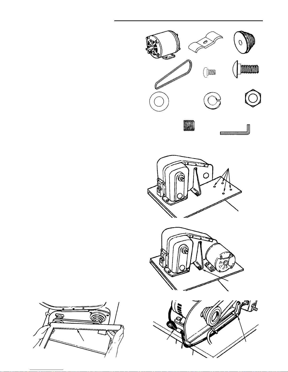
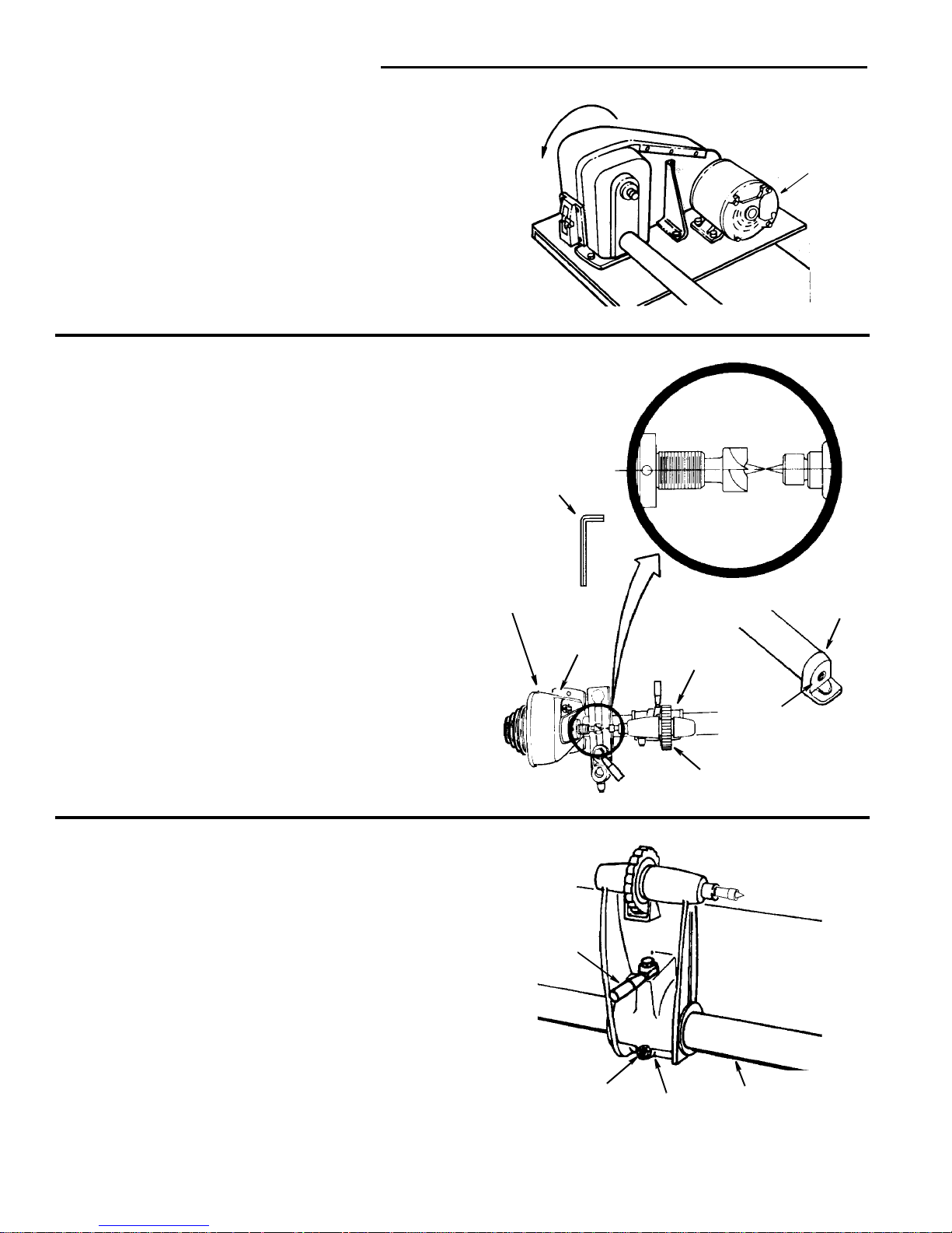
Mounting the Motor
1. Find the following:
1 Motor
1 Motor Pulley
2CordClamps
1V-Belt
2. From the loose parts package find the following:
2 M4 x 0.7-6 Pan Head S crews
4 M6 x 1.0-16 Carriage Bolts
4 6.5 x 19 x 1.6 Flat Washers
4 6mm Lockwashers
4 M6x1.0HexNuts
1 M8 x 1.25-8 Socket Set Sc rew
1 4mm Hex “L” W rench
3. Loc ate the four holes Labeled H on the plate support.
4. Place the motor over these holes with the motor shaft
extending through the belt guard plate. Se cure in place
with carriage bolts, washers, lockwashers and nuts.
5. Plug motor cord into outlet on back of switch box. Do
Not plug motor cord into power source outlet.
6. Route the motor cord along side the headstock as
shown. Secure the motor cord with two cord clamps
and an M4 x 0.7-6 pan head screw into the tapped
holes Labeled J in the motor mount ing plate.
7. Place the motor pulley on the motor shaft so that the
small diameter is approximately 1/16" away from the
motor. Tighten the setscrew with the 4mm Hex “L”
wrench securelyagainst the flat spot on the motor shaft.
8. Place the belt on the pulleys and slide the motor
toward the rear of workbench until all the slack is
removed from the belt. Tighten only two of the motor
mounting bolts at this time.
NOTE: 1/2 inch deflection of belt under moderate pressure applied between the two pulleys is adequate tension.
9. Place a straightedge such as a piece of wood, metal or
framing square across the pulleys to see if they are in
line with each other. If they are, tighten the o ther two
motor mounting bolts. If they are not in line, loosen the
two motor bol ts and move the motor sideways until pulleys are in lin e. Tighten the bolts.
NOTE: Changing speeds ic accom plished by repositioning the V-Belt on the pull eys (see Changing
Speeds” section). There needs to be sufficient slack in
theV-belttoallowforthis.
Carriage Bolt
M6x1.0-16
Motor
Hex Nut
M6 x 1.0
Pan S crew
M4 x 0.7-6
Cord Clamp
4mm Hex “L” Wrench
Lockwasher
6mm
Washer
6.5x19x1.6
Socket Set Screw
M8 x 1.25-8
Motor Pulley
V-Belt
Straightedge
Motor
Cord
Clamps
Cord
Assembly (continued)
Plate Bracket
Holes for Mounting
Motor (H)
13
Headstock,Tailstock, and Tool Rest Assembly
1. Find the following:
1Tube
1 Large Tool Rest
1Tailstock
2 Lever Assembly
1 Socket Set Screw M10 x 1.5-12
1 Tool Rest Holder/Clamp Support Assembly
2 Brass Shoe Locks
1 5mm Hex “L” Wrench
2. Place the tub e assembly on your work bench as shown.
Always keep the squared key section straight down.
3. Slide the tube into the heads t ock until it stops against
the squared key section. Insert locking sets c rew and
tighten with 5mm hex “L” wrench.
4. Slide the tool rest holder/clamp support assembly onto
the middle of the tube. A ssem ble lock lever as shown.
5. Set large tool rest in tool res t holder and in stall locking
lever as shown.
Tube
Tailstock
Large Tool Rest
Tool Rest Holder/
Clamp Support Assembly
Lever Assem bly
BrassShoeLock
Socket Set Screw
M10 x 1.5-12
5mm Hex “L” Wrench
Tube Assembly
Squared Key Section
Spindle Pulley
Headstock Spindle
Tube
Squared Key
Section
Stock-Tube Locking
Screw in Rear of
Headstock
Headstock
End
Clamp Support
Brass Shoe
Lever
Lock
Assembly
Tool Rest
Lever Assem bly
14
Assembly (continued)
6. Slide tailstock ass embly onto the tube and install tai lstock ram spindle lock lever. Be sure that the stud nut
engages the keyed way of the spindle.
7. On the backside of the tailstock, assem ble the locking
devicesas shown.
Mounting Rear Foot
1. Locate the following:
1 M8 x 1.25-45 Pan Head Screw
1 M8 x 1.25 S quare Nut
1 M6 x 1.0-65 Carriage Bolt
1 6.5 x 19 x 1. 6 Flat Washer
1 6mmLockwasher
1 M6x1.0HexNut
2. Install the rear foot onto the tube as shown and tighten
rear foot locking screw. Foot will wedge into plate as
screw is tightened. T his may take several attempts.
3. Attach the rear foot on the right side table board, hole
labeled K. Secure in pla ce with bolt, washer, lockwasher and nut as shown.
Lever
Tailstock Ram
Keyed Way
Headstock End
Tailstock
Spindle
Assembly
Assembly
Lever
Headstock End
Tailstock Assembly
Brass Shoe
Lock
Assembly
Nut Hex
M6 x 1.0
Carriage Bolt
M6 x 1.0-65
PanHeadScrew
M8 x 1.25-45
Nut Square
M8 x 1.25
Flat Washer
6.5 x 19 x 1.6
Lockwasher
6mm
Tube Assembly
Rear Foot
Square
Nut
Pan Head Scre
w
M8 x 1.25-45
Headstock End
Hole K
Carriage Bo lt
M6 x 1.0-65
Washer
Lockwasher
Nut

15
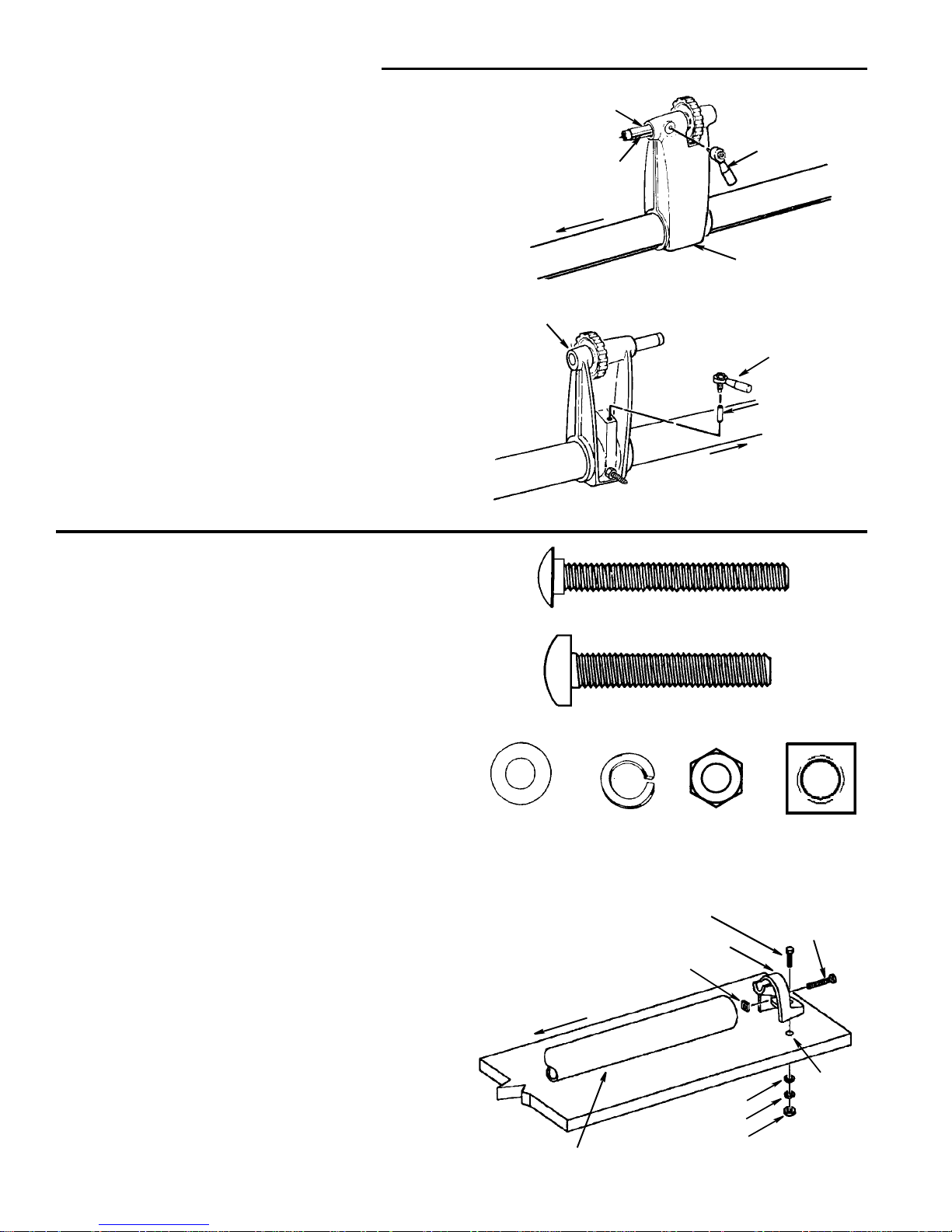
Spur and Cup Center Installation
1. From the loose parts package find the following:
13/4-16HexNut
1 Spur Center
1 Cup Center
2. Screw nut onto head stock spindle until finger tight.
3. To insert point into centers, place center between j aws
of a vise. Do not tighten vice. Insert point into cent er
and with a hammer and nail gently tap around the base
of t he point until secure.
NOTE: A piece of cloth may be wrapped around the centers to protec t them bef ore inserting into a vise.
4. Insert spur center into head stock s pindle and cu p
center into tailstock ram.
NOTE: Do not drive or hamme r centers into spindle or
ram as removal may be difficult. Use a soft hammer or
block of wood and give them a gentle tap.
5. To remove spur center from spindle, hold the spindle
pulley with one hand, and, using a wrench, turn the
hex nut counterclockwise until center is ejected. Do
not us e index pin to hold pulley.
6. To remove cup center insert a 1/4" dia. wood dowel
or brass rod through the hole in the tailstock ram.
Hold the center with one hand and tap the dowel or
rodwithahammer.
Hex Nu t 3/4-16
Cup Center
Tailstock Ram
1/4" Dia.
Wood Dowel
Foot
16
Assembly (continued)
Check Spindle Rotation
The lathe spindle must rotate counterclockwise when
viewed from the spindle end.
NOTE: Make sure the spur center is removed from the
spindle.
1. Plug the lathe power cord into a proper ly grounded
outlet (See page 5)
2. Stand clear of the lathe spindle and turn the switch
On. Notice the rotation of the spindle. If it is Not turning Cou nterclockwise contact your Authorized Service Center immediately before us ing t his tool.
Aligning Centers
If the centers are not in line as shown, make the following
adjustments.
1. Make sure the tailstock and ram are locked when
checking for alignment.
2. Loosen the screw in the foot... Tap the screw to loosen
the locknut inside.
3. Using a 5mm hex “L” wrench, loosen the setscrew on
the back of the headstock. The screw is lo cated about
1-3/4" from the bottom.
4. Swing the tailstock so that the two points are in line...
tighten the setscr ew i n the headstock and the screw in
the end of the tailstock.
Adjusting Tailstock
The tailstock c ontains a brass screw which bears against
the "key" on the underside of the bed. This screw prevents
excessive "looseness" (rocking back and forth) of the tailstock.
1. Loosen the locknut using a 13mm w renc h.
2. Tighten the screw moderat ely against the key, then
loosen it about 1/4 turn.
Slide the tailsto ck along the bed. If it does not stick or bind
in any one spot, tighten the nut. If it binds or sticks, loosen
the screw only enough so that the tailstock slides smoothly along the bed.
Rotation
Terminal
Cover
5mm Hex “L”
Wrench
Headstock
3/16"
Set Screw
Tailstock
Handwheel
Screw
Foot
Tailstock
Lock
Brass
Screw
Locknut
Key
 Loading...