

RIDGID SeeSnake Max rM200 Operator's Manual

Operator’s Manual
WARNING!
Read this Operator’s Manual carefully before using
this tool. Failure to understand and follow the contents of this manual may
result in electrical shock,
fire and/or serious personal injury.
Record product serial number below as it appears on the nameplate.
Serial
No.
Original Instructions – English – 1

Table of Contents
Serial Number Recording Form ��������������������������������������������������������������������������������������������������������������������������������������� 1
Safety Symbols �����������������������������������������������������������������������������������������������������������������������������������������������������������������3
General Safety Rules ��������������������������������������������������������������������������������������������������������������������������������������������������������3
Work Area Safety �����������������������������������������������������������������������������������������������������������������������������������������������������������3
Electrical Safety �������������������������������������������������������������������������������������������������������������������������������������������������������������3
Personal Safety��������������������������������������������������������������������������������������������������������������������������������������������������������������3
Equipment Use and Care ����������������������������������������������������������������������������������������������������������������������������������������������3
Service ��������������������������������������������������������������������������������������������������������������������������������������������������������������������������4
Specific Safety Information ���������������������������������������������������������������������������������������������������������������������������������������������4
SeeSnake M
Description, Specifications, and Standard Equipment
rM200 Components ���������������������������������������������������������������������������������������������������������������������������������������������������������� 6
Directional Drag Brake ���������������������������������������������������������������������������������������������������������������������������������������������������6
Assembly ���������������������������������������������������������������������������������������������������������������������������������������������������������������������������6
Camera Head Routing ���������������������������������������������������������������������������������������������������������������������������������������������������6
Installing System Cable �������������������������������������������������������������������������������������������������������������������������������������������������7
rM200 Pipe Guides �������������������������������������������������������������������������������������������������������������������������������������������������������� 7
rM200 Handles and Docks ��������������������������������������������������������������������������������������������������������������������������������������������8
Pre-Operation Inspection ������������������������������������������������������������������������������������������������������������������������������������������������9
Work Area and Equipment Set Up �����������������������������������������������������������������������������������������������������������������������������������9
rM200 Placement ��������������������������������������������������������������������������������������������������������������������������������������������������������10
Connecting the rM200 to a CCU ���������������������������������������������������������������������������������������������������������������������������������� 10
Electrical Checks ��������������������������������������������������������������������������������������������������������������������������������������������������������� 10
Counter ������������������������������������������������������������������������������������������������������������������������������������������������������������������������ 10
Operating Instructions ��������������������������������������������������������������������������������������������������������������������������������������������������� 11
Retrieving the Camera ������������������������������������������������������������������������������������������������������������������������������������������������ 13
Maintenance and Cleaning �������������������������������������������������������������������������������������������������������������������������������������������� 13
Camera Maintenance ��������������������������������������������������������������������������������������������������������������������������������������������������13
Push Cable Maintenance ��������������������������������������������������������������������������������������������������������������������������������������������� 15
Rewinding the Push Cable ������������������������������������������������������������������������������������������������������������������������������������������� 15
Accessories ���������������������������������������������������������������������������������������������������������������������������������������������������������������������16
Transport and Storage ���������������������������������������������������������������������������������������������������������������������������������������������������16
Service and Repair ���������������������������������������������������������������������������������������������������������������������������������������������������������16
Disposal ��������������������������������������������������������������������������������������������������������������������������������������������������������������������������16
Troubleshooting Faulty Components ���������������������������������������������������������������������������������������������������������������������������16
Troubleshooting �������������������������������������������������������������������������������������������������������������������������������������������������������������� 17
ax rM200 Safety ���������������������������������������������������������������������������������������������������������������������������������������4
�������������������������������������������������������������������������������������������������5
2 – English
Safety Symbols
In this operator’s manual and on the product, safety symbols and signal words are used to communicate important
safety information� This section is provided to improve understanding of these signal words and symbols�
This is the safety alert symbol� It is used to alert you to potential personal injury hazards� Obey all safety messages that follow
this symbol to avoid possible injury or death�
DANGER
WARNING
CAUTION
NOTICE
This symbol means read the operator’s manual carefully before using the equipment� The operator’s manual contains important
information on the safe and proper operation of the equipment�
This symbol means always wear safety glasses with side shields or goggles when handling or using this equipment to reduce
the risk of eye injury�
This symbol indicates the risk of electrical shock�
DANGER indicates a hazardous situation which, if not avoided, will result in death or serious injury�
WARNING indicates a hazardous situation which, if not avoided, could result in death or serious injury�
CAUTION indicates a hazardous situation which, if not avoided, could result in minor or moderate injury�
NOTICE indicates information that relates to the protection of property�
General Safety Rules
WARNING
Read all safety warnings and instructions. Failure to follow the warnings and instructions may result in electric
shock, re, and/or serious injury.
SAVE THESE INSTRUCTIONS!
Work Area Safety
• Keep your work area clean and well lit� Cluttered or
dark areas invite accidents�
• Do not operate equipment in explosive atmospheres,
such as in the presence of flammable liquids, gases,
or dust� Equipment can create sparks which may ignite
the dust or fumes�
• Keep children and bystanders away while operating
equipment� Distractions can cause you to lose control�
Electrical Safety
• Avoid body contact with earthed or grounded sur-
faces such as pipes, radiators, ranges, and refrigerators� There is an increased risk of electrical shock if your
body is earthed or grounded�
• Do not expose equipment to rain or wet conditions�
Water entering equipment will increase the risk of electrical shock�
• Do not abuse the cord� Never use the cord for carrying,
pulling, or unplugging the power tool� Keep cord away
from heat, oil, sharp edges, and moving parts� Damaged
or entangled cords increase the risk of electric shock�
• If operating equipment in a damp location is un-
avoidable, use a ground fault circuit interrupter
(GFCI) protected supply� Use of a GFCI reduces the
risk of electric shock�
• Keep all electrical connections dry and off the
ground� Do not touch equipment or plugs with wet
hands to reduce the risk of electrical shock�
Personal Safety
• Stay alert, watch what you are doing, and use com-
mon sense when operating equipment� Do not use
equipment while you are tired or under the influence of
drugs, alcohol, or medication� A moment of inattention
while operating equipment may result in serious personal injury�
• Use personal protective equipment� Always wear eye
protection� The appropriate use of protective equipment
such as a dust mask, non-skid safety shoes, a hard hat,
and hearing protection will reduce personal injuries�
• Do not overreach� Keep proper footing and balance at
all times� This enables better control of the equipment in
unexpected situations�
• Dress properly� Do not wear loose clothing or jewelry�
Keep your hair, clothing, and gloves away from moving parts� Loose clothes, jewelry, and long hair can be
caught in moving parts�
Equipment Use and Care
• Do not force equipment� Use the correct equipment for
your application� The correct equipment will do the job
better and safer at the rate for which it is designed�
• Do not use equipment if the power switch does not
turn it ON and OFF� Any equipment that cannot be controlled with the power switch is dangerous and must be
repaired�
English – 3

• Disconnect the plug from the power source and/or
the battery pack from the equipment before making
adjustments, changing accessories, or storing� Pre-
ventive safety measures reduce the risk of injury�
• Store idle equipment out of the reach of children
and do not allow persons unfamiliar with the equipment or these instructions to operate the equipment�
Equipment can be dangerous in the hands of untrained
users�
• Maintain equipment� Check for misalignment or bind-
ing of moving parts, missing parts, breakage of parts,
and any other condition that may affect the equipment’s
operation� If damaged, have the equipment repaired before use� Many accidents are caused by poorly maintained equipment�
• Use the equipment and accessories in accordance
with these instructions; taking into account the
working conditions and the work to be performed�
Use of the equipment for operations different from those
intended could result in a hazardous situation�
• Use only accessories that are recommended by the
manufacturer for your equipment� Accessories that
may be suitable for one piece of equipment may become
hazardous when used with other equipment�
• Keep handles dry, clean, and free from oil and grease�
This allows for better control of the equipment�
Service
• Have your equipment serviced by a qualified repair
person using only identical replacement parts� This
will ensure that the safety of the equipment is maintained�
Specic Safety Information
WARNING
This section contains important safety information that
is specic to the rM200. Read these precautions carefully before using the rM200 to reduce the risk of electrical
shock, re, or other serious personal injury.
SAVE ALL WARNINGS AND INSTRUCTIONS
FOR FUTURE REFERENCE!
Keep this manual with the rM200 for use by the operator�
SeeSnake Max rM200 Safety
• An improperly grounded electrical outlet can cause
electrical shock and/or severely damage equipment�
Always check work area for a properly grounded elec-
trical outlet� Presence of a three-prong or GFCI outlet
does not ensure that the outlet is properly grounded� If in
doubt, have the outlet inspected by a licensed electrician�
• The rM200 system camera and push cable are water-
proof� The camera control unit (CCU) and other electrical equipment and connections are not waterproof� To
decrease the risk of electrical shock, do not expose the
equipment to water or rain�
• Do not use where a danger of high voltage contact is
present� The equipment is not designed to provide high
voltage protection and isolation�
• Read and understand this operator’s manual, the
CCU’s operator’s manual and the instructions for
any other equipment in use before operating the
SeeSnake rM200 System� Failure to follow all instruc-
tion may result in property damage and/or serious personal injury�
• Always use appropriate personal protective equip-
ment when handling and using equipment in drains�
Drains may contain chemicals, bacteria, and other substances that may be toxic, infectious, cause burns or
other issues� Appropriate personal protective equipment
always includes safety glasses and may include drain
cleaning gloves or mitts, latex or rubber gloves, face
shields, goggles, protective clothing, respirators, and
steel toed footwear�
• If using drain cleaning equipment and drain inspec-
tion equipment at the same time, wear RIDGID drain
cleaning gloves� Never grasp the rotating drain clean-
ing cable with anything else, including other gloves or a
rag which can become wrapped around the cable and
cause hand injuries� Only wear latex or rubber gloves
under RIDGID drain cleaner gloves� Do not use damaged drain cleaning gloves�
• Practice good hygiene� Use hot, soapy water to wash
hands and other body parts exposed to drain contents
after handling or using drain inspection equipment� To
prevent contamination from toxic or infectious material,
do not eat or smoke while operating or handling drain
inspection equipment�
The information supplied with this product cannot
cover all possible conditions and situations that may
occur, and should be used in conjunction with appro-
priate training, sound judgment, and good work practices� These factors cannot be built into the product,
but must be supplied by the operator�
The EC Declaration of Conformity (890-011-320�10) will accompany this manual as a separate booklet when required�
• Do not operate this equipment if operator or rM200
is standing in water� Operating the rM200 while in
water increases the risk of electrical shock�
4 – English
Description, Specications, and
Standard Equipment
Description
The SeeSnake Max rM200 is the first camera reel in the
next generation of SeeSnake Pipe Inspection systems� The
SeeSnake Max line has been designed to make your equipment more reliable, durable, and to enable you to deliver
quality recordings to customers faster and more conveniently than ever before�
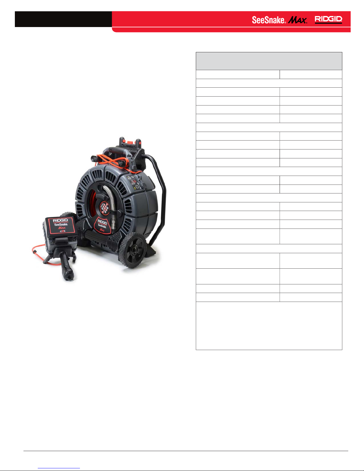
Figure 1 – SeeSnake MAX System, rM200 with cM6
The rM200 is a rugged reel and camera system that en-
ables you to diagnose and locate problems in drain and
sewer systems� The rM200 is equipped with a 200 ft [60 m]
push cable that combines low optimum stiffness with a lowfriction outer jacket� As a result of the push cable outer jacket, users can push the camera head further with less effort�
In addition to the specialized outer jacket on the push cable,
the small diameter and short body of the rM200 camera allows user to push the push cable through multiple turns and
lines as small as 1�5 in [40 mm] in diameter�
The rM200 comes with a built-in sonde, integrated counter,
and a removable system cable that can be connected to
any SeeSnake Max or SeeSnake Original CCU�
Specifications
Table 1
SeeSnake MAX rM200 Specifications
Weight 34�1 lb [15�5 kg]
Dimensions:
Length
Depth 13�8 in [349 mm]
Height 24�0 in [610 mm]
Drum diameter 17�0 in [432 mm]
Camera specifications:
Length
Diameter* ≥1�0 in [25 mm]*
Sonde 512 Hz
Lighting 6 high flux LEDs
Resolution:
NTSC 648 × 488 pixels
PA L 768 × 576 pixels
Push cable:
Length 200 ft [61 m]
Diameter
Bend radius ≥ 4�0 in [100 mm]
Pipe capacity
Operating environment:
Temperature
Storage temperature
Humidity 5% – 95% RH
Waterproof depth 225 ft [69 m]
* The camera size listed reflects the specifications of
the camera on the base model� Other models of the
rM200 may accommodate cameras up to 1�4 in [35
mm] in diameter�
† While the sensor will function in the extreme tempera-
tures, some image quality changes may be noticed�
†
20�8 in [527 mm]
1�25 in [31�75 mm]
0�3 in [7�5 mm]
1�5 in – 6�0 in
[38 mm – 150 mm]
−40°F – 130°F
[−40°C – 55°C]
−40°F – 150°F
[−40°C – 65°C]
Standard Equipment
• SeeSnake Max rM200
• Operator’s manual
• Instructional DVD
• Ball guides
• Camera head guide
• Docking handle
• Directional drag brake
English – 5
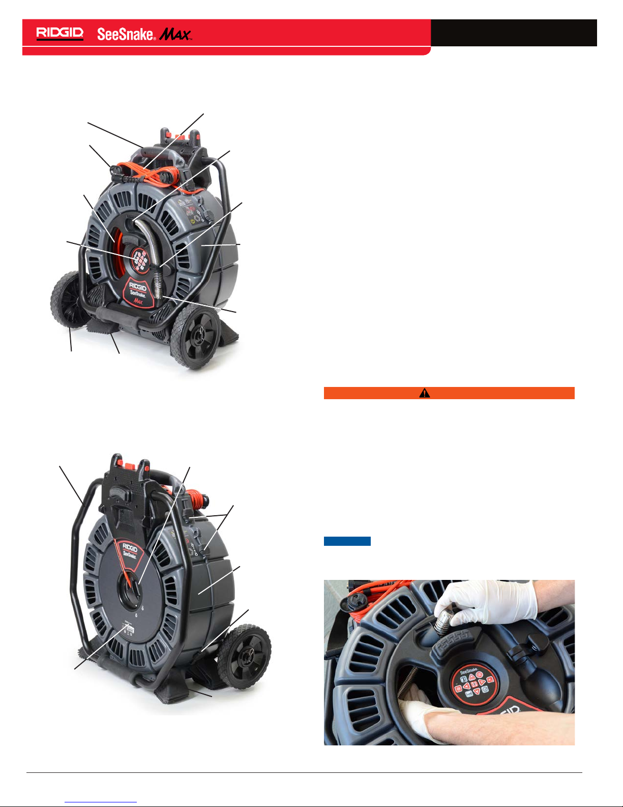
rM200 Components
Carry grip
Cord Wrap
Hole to reach
camera for
routing
Integrated
Counter
Keypad
Wheels
Feet
System Cable for
SeeSnake CCU
Push Cable
Guide
Camera
Clip
Front
Case
Camera
Head
Directional Drag Brake
The rM200 also contains a built-in directional drag brake
that prevents the push cable from self-deploying, but also
allows the user to rewind the push cable with ease� Unlike
other reels that contain brake knobs that require manual
adjusting, the directional drag brake automatically applies
drag when the push cable is pulled from the reel and auto-
matically loosens drag when the push cable is returned to
the reel� The directional drag brake uses a unique series of
ball bearings, ratchets, and ramps to increase or decrease
drag on the push cable� Depending on the direction of the
drum rotation, the directional drag brake automatically elic-
its either higher or lower force�
When the user pulls the push cable from the rM200, the
directional drag brake will automatically increase the drag
on the push cable to ensure a controlled release� While pull-
ing the push cable from the rM200, the user will hear a dis-
tinct “click” noise� The “click” acts as an audible cue to indicate the effectiveness of the drag-assisted control� While
the “click” sound will diminish slightly with wear, replace the
back bearing assembly when the click is inaudible or the
drag becomes ineffective�
Assembly
Figure 2 – Front view
Pull Handle
Serial Number
Label
Slip-Ring
Assembly/
Module
Case Latches
Rear
Case
Case
Latch
Feet
WARNING
To reduce the risk of serious injury, follow these procedures for proper assembly.
Camera Head Routing
The rM200 has been designed such that the camera head
can be routed without opening up the case� Route the camera by reaching inside the case through the opening on the
front and by feeding the camera head into the push cable
guide� Secure the camera head in the camera clip when
not in use�
NOTICE
camera head and to help guide the camera head
through the push cable guide�
Only use the big hole to initially locate the
Figure 3 – Rear view
6 – English
Figure 4 – Camera head routing
 Loading...