

Page 1
INSTALLATION INSTRUCTIONS
SAE COMPLIANT LIGHTS
*THESE INSTRUCTIONS ARE FOR THE FOLLOWING LIGHTS:
(2) SAE SR-M
®
, (2) SAE D-XL
®
, (2) SAE Q-SERIES
®
IMPORTANT
THANK YOU FOR PURCHASING RIGID INDUSTRIES’ PRODUCTS FOR YOUR VEHICLE.
Please read through all of these Instructions and tips before proceeding with the installation.
We do our best to provide a simple installation process for all applications however
a professional installation is always recommended.
Always disconnect any power sources connected to your vehicle
before servicing fuses or electrical systems.
Page 2
WIRING INSTRUCTIONS
SAE D-SERIES
1. Place 5/16-18 Carriage Bolt (E) into
Mounting Bracket (D).
2. Use M6 Allen Socket Head (B) and
M6 Nyloc Nut (C) to attach Mounting
Bracket (D) to Housing (A).
3. Drill a 5/16” hole into desired
mounting location.
4. Use 5/16”: Flat Washer (F), Lock
Washer (G), and Nut (H) to secure
light assembly to vehicle.
5. Tighten all hardware.
SAE E-SERIES
1. Place 1/4-20x1” hex head bolt (C)
into Light housing (A).
2. Next insert mount bushing onto
the 1/4-20 hex head bolt (C).
3. Choose desired mounting height
and place supplied mounting
bracket (E) over mounting stud (C).
4. Secure the mounting assembly
with 1/4” at washer (D) and 1/4-20
Nyloc nut (B).
5. Tighten all hardware.
A - LED Light (Housing)
B - M6 Allen Socket
Head (2)
C - M6 Nyloc Nut (2)
D - Mounting Bracket
B - 1/4-20 Nyloc Nut
C - 1/4-20 HEX Bolt
D - 1/4” Flat Washer
* Long and short brackets provided for additional mounting congurations
E - 5/16-18 Carriage Bolt
F - 5/16” Flat Washer
G - 5/16” Flat Washer
H - 5/16-18 Nut
E - Mounting BracketA - LED Light (Housing)
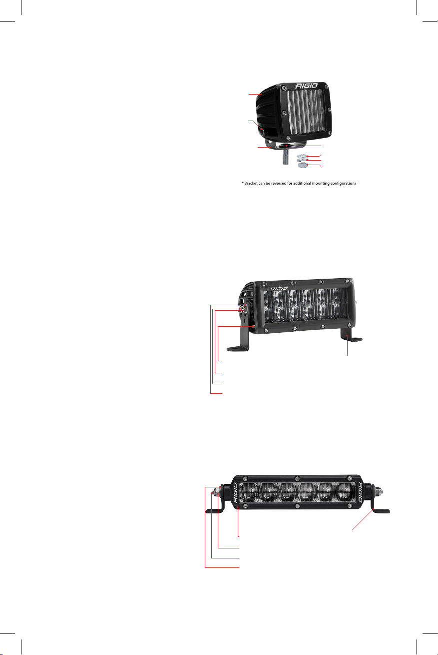
SAE SR-SERIES
1. Place 1/4-20x1” hex head bolt (C)
into Light housing (A).
2. Next insert mount bushing onto
the 1/4-20 hex head bolt (C).
3. Choose desired mounting height
and place supplied mounting
bracket (E) over mounting stud (C).
4. Secure the mounting assembly
with 1/4” at washer (D) and 1/4-20
Nyloc nut (B).
5. Tighten all hardware.
E - Mounting BracketA - LED Light (Housing)
B - 1/4-20 Nyloc Nut
C - 1/4-20 HEX Bolt
D - 1/4” Flat Washer
* Long and short brackets provided for additional mounting congurations
Page 3

SAE SR-M SERIES
Place 5/16-18 Carriage Bolt (E) into Mounting Bracket (D). Use the M6 Allen Socket Head (B) and the
M6 Nyloc Nut (C) to attach the Mounting Bracket (D) to the Housing (A). Drill a 5/16” hole into desired
mounting location. Use the 5/16”: Flat Washer (F), Split Washer (G), and Nut (H) to secure the light
assembly to vehicle. Finally tighten all hardware. (See Figure below)
A - LED Light (Housing)
B - M6 Allen Socket Head (1)
C - M6 Nyloc Nut (1)
D - Mounting Bracket
E - 5/16-18 Carriage Bolt
F - 5/16” Flat Washer
G - 5/16” Split Washer
H - 5/16-18 Nut
SAE D-XL SERIES
Step 1
Assemble the LED Light Kit by attaching mounting bracket to the housing using the provided mount
bushings, bolts, washers and low prole nylock nuts. Place mount bushings into the housing prior to
installing mounting bracket. (See Figure Below)
Mount Bushing
1/4” Flat Washer
#10 Flat Washer
10-24 Low Prole Lock Nut 1/4-20 x 4.5” Socket Cap Screw
1/4-20 Low Prole Lock Nut 10-24 x 4.5” Socket Cap Screw
Step 2
Mount completed LED Light Assembly using the remaining bolt, washers, and nut. Vibration Isolators
are included in the kit, but are not necessary. A 7/16” hole is required to mount the Light Assembly.
(Torque to 212 in/lbs) (See Figure Below)
3/8” -16
Carriage
Bolt
Rubber
Shock
Isolation
Mount
3/8” Flat Washer
3/8” Split Washer
3/8” Hex Nut
Page 4

SAE Q-SERIES
Mountin
g
Step 1
The illustration blow demonstrates how the nuts will be held in place by the Mount Bushings. This
pertains to both the left and right sides of the housing. (See Figure Below)
Mount Bushing
M6 Square Nut
M8x1.25 Hex Nut
Step 2
You will need to choose if you would like to mount your light in a stationary position or with one larger
bolt, giving you the ability to swivel the light.
(Torque to 212 in/lbs) (See Figure Below)
Stationary Mount
Mounting Bracket
Mounting Surface
3/8” Flat Washer
3/8” Split Washer
3/8” Hex Nut
3/8” -16
Carriage
Bolt
Rubber
Shock
Isolation
Mount
Swivel Mount
Mounting Bracket
3/8” Flat Washer
3/8” Split Washer
3/8” Hex Nut
Surface
3/8” -16
Carriage
Bolt
Rubber
Shock
Isolation
Mount
Step 3
Secure light to mounting bracket by following the diagram below. Be sure to install the washers and
Split washers in the correct order to ensure proper installation. This pertains to both the left and right
sides of the bracket. (See Figure Below)
M8 x 1.25 Hex Bolt / Split Washer / Flat Washer
M6 x 1.0 Hex Bolt / Split Washer / Flat Washer
Mount Bushing
Page 5

WIRING INSTRUCTIONS
IMPORTANT
Always disconnect the vehicle batter terminals before servicing the electrical system
Fuse
Relay
Switch
Battery Eyelets
Deutsch Connector
1. When routing wire harness through any metal surface be sure it is free of any sharp edges and
protected using wire sheathing or a grommet.
2. Route the harness through vehicle, connect the SAE lamps by directly plugging into the Deutsch
connector’s that are pre-terminated onto the harness.
3. Route the switch lead of the harness to the desired switch location and follow the wiring diagram to
ensure proper connections at the switch.
4. Connect the positive and negative battery terminals once all connections have been made with
the RED harness lead connected to the positive battery terminal and the BLACK wire to the negative
battery terminal.
5. Test to verify functionality, be sure to properly aim your new SAE lighting before nal torque on all
mounting hardware.
6. If connecting to an existing switch be aware of the current rating of your selected switch, if switch
rating is less than the amperage required to power your lighting then a relay must be added in line to
prevent failure of the switch.
7. If connecting to existing wiring, make sure to use appropriate fusing and wire gauge. Be sure to use
heat shrink tubing on all connections to ensure a weather tight seal.
RELAY HARNESS
NOTE: GOLD Spade is the Top of Switch, 3/4” mounting hole required
Black Wire
3
2
1
Wiring: Wire your lights according to the instructions included with the light.
Take care to avoid any heat sources and sharp or abrasive surfaces.
For warranty information, visit www.rigidindustries.com/about/warranty
D-Se ries, D-XL, Q-Serie s and Rig id Industr ies are registered and/or common law marks owned by JST Performance,
LLC, a Delaware limited liability company d/b/a Rigid Industries.
= Switch Ground
Blue Wire/Red Wire w/ Heat Shrink
= Switch Output to Relay
Red Wire
= Switch Input Power
11-12671-A
 Loading...