

RIDGID RSS-1000 Operating Instructions And Parts Manual

Model, Modèle, Modelo
S
o
Preassembled Sump System
RSS-1000
OPERATING INSTRUCTIONS
AND PARTS MANUAL
MANUEL DE PIÈCES ET
MODE D’EMPLOI
MANUAL DE INSTRUCCIONES
DE FUNCIONAMIENTO Y
PIEZAS DE REPUESTO
Système de pompe immergée
préassembleé
istema de sumidero preensamblad
Sistema de sumidero preensamblado
WARNING
READ UNDERSTAND AND
FOLLOW ALL INSTRUCTIONS
IN THIS MANUAL — DO NOT
DISCARD. Failure to understand
and follow the contents of this
manual may result in electrical
shock, fire and/or serious
personal injury.
!
AVER TISSEMENT!
LIRE, COMPRENDRE ET SUIVRE
TOUTES LES INSTRUCTIONS
DANS CE MANUEL — NE PAS
JETER. Ne pas comprendre et
ne pas suivre les contenus de ce
manuel peut avoir pour résultat
un choc électrique, de feux et/ou
de blessures personnelles graves.
¡
ADVERTENCIA!
LEA, ENTIENDA Y SIGA
TODAS LAS INSTRUCCIONES
DE ESTE MANUAL — NO LAS
DESECHE. El no entender
y no seguir el contenido de
este manual puede dar como
resultado un choque eléctrico,
incendios y/o lesiones graves.

Operating Instructions and Parts Manual
Model, Modèle, Modelo – RSS-1000 Manuel de pièces et mode d’emploi
Manual de instrucciones de funcionamiento y piezas de repuesto
Table of Contents
Description . . . . . . . . . . . . . . . . . . . . . . . . . . . . . . . . . . . . . . . . . . . . . . . . . . . . . . . . . . . . . . . . . . . . . . . . . . . . . . . . . . . . . . . . . . . . . . . . . 1
Unpacking . . . . . . . . . . . . . . . . . . . . . . . . . . . . . . . . . . . . . . . . . . . . . . . . . . . . . . . . . . . . . . . . . . . . . . . . . . . . . . . . . . . . . . . . . . . . . . . . . 1
Safety Guidelines . . . . . . . . . . . . . . . . . . . . . . . . . . . . . . . . . . . . . . . . . . . . . . . . . . . . . . . . . . . . . . . . . . . . . . . . . . . . . . . . . . . . . . . . . . . . 1
System Specifications . . . . . . . . . . . . . . . . . . . . . . . . . . . . . . . . . . . . . . . . . . . . . . . . . . . . . . . . . . . . . . . . . . . . . . . . . . . . . . . . . . . . . . . . 1
System Construction . . . . . . . . . . . . . . . . . . . . . . . . . . . . . . . . . . . . . . . . . . . . . . . . . . . . . . . . . . . . . . . . . . . . . . . . . . . . . . . . . . . . . . . . . 1
General Safety Information . . . . . . . . . . . . . . . . . . . . . . . . . . . . . . . . . . . . . . . . . . . . . . . . . . . . . . . . . . . . . . . . . . . . . . . . . . . . . . . . . 1 - 2
Specific Safety Information . . . . . . . . . . . . . . . . . . . . . . . . . . . . . . . . . . . . . . . . . . . . . . . . . . . . . . . . . . . . . . . . . . . . . . . . . . . . . . . . . . . . 2
Back-up Pump Battery Requirements . . . . . . . . . . . . . . . . . . . . . . . . . . . . . . . . . . . . . . . . . . . . . . . . . . . . . . . . . . . . . . . . . . . . . . . . . . . 2
System Installation . . . . . . . . . . . . . . . . . . . . . . . . . . . . . . . . . . . . . . . . . . . . . . . . . . . . . . . . . . . . . . . . . . . . . . . . . . . . . . . . . . . . . . . . 2 - 3
System Operation . . . . . . . . . . . . . . . . . . . . . . . . . . . . . . . . . . . . . . . . . . . . . . . . . . . . . . . . . . . . . . . . . . . . . . . . . . . . . . . . . . . . . . . . . . . 3
Maintenance Instructions . . . . . . . . . . . . . . . . . . . . . . . . . . . . . . . . . . . . . . . . . . . . . . . . . . . . . . . . . . . . . . . . . . . . . . . . . . . . . . . . . . 3 - 4
Troubleshooting Chart . . . . . . . . . . . . . . . . . . . . . . . . . . . . . . . . . . . . . . . . . . . . . . . . . . . . . . . . . . . . . . . . . . . . . . . . . . . . . . . . . . . . . . . . 4
Recording Form for Pump Serial Number . . . . . . . . . . . . . . . . . . . . . . . . . . . . . . . . . . . . . . . . . . . . . . . . . . . . . . . . . . . . . . . . . . . . . . . 5
Contact Information . . . . . . . . . . . . . . . . . . . . . . . . . . . . . . . . . . . . . . . . . . . . . . . . . . . . . . . . . . . . . . . . . . . . . . . . . . . . . . . . . . . . . . . . . 5
Replacement Part List . . . . . . . . . . . . . . . . . . . . . . . . . . . . . . . . . . . . . . . . . . . . . . . . . . . . . . . . . . . . . . . . . . . . . . . . . . . . . . . . . . . . . . . 5
Exploded View . . . . . . . . . . . . . . . . . . . . . . . . . . . . . . . . . . . . . . . . . . . . . . . . . . . . . . . . . . . . . . . . . . . . . . . . . . . . . . . . . . . . . . . . . . . . . . 5
Notes . . . . . . . . . . . . . . . . . . . . . . . . . . . . . . . . . . . . . . . . . . . . . . . . . . . . . . . . . . . . . . . . . . . . . . . . . . . . . . . . . . . . . . . . . . . . . . . 6, 19 - 21
Warranty . . . . . . . . . . . . . . . . . . . . . . . . . . . . . . . . . . . . . . . . . . . . . . . . . . . . . . . . . . . . . . . . . . . . . . . . . . . . . . . . . . . . . . . . . Back Cover
Table des matières
Description . . . . . . . . . . . . . . . . . . . . . . . . . . . . . . . . . . . . . . . . . . . . . . . . . . . . . . . . . . . . . . . . . . . . . . . . . . . . . . . . . . . . . . . . . . . . . . . . . 7
Déballage. . . . . . . . . . . . . . . . . . . . . . . . . . . . . . . . . . . . . . . . . . . . . . . . . . . . . . . . . . . . . . . . . . . . . . . . . . . . . . . . . . . . . . . . . . . . . . . . . . . 7
Directives de sécurité . . . . . . . . . . . . . . . . . . . . . . . . . . . . . . . . . . . . . . . . . . . . . . . . . . . . . . . . . . . . . . . . . . . . . . . . . . . . . . . . . . . . . . . . 7
Spécifications de la système . . . . . . . . . . . . . . . . . . . . . . . . . . . . . . . . . . . . . . . . . . . . . . . . . . . . . . . . . . . . . . . . . . . . . . . . . . . . . . . . . . 7
Construction de la système . . . . . . . . . . . . . . . . . . . . . . . . . . . . . . . . . . . . . . . . . . . . . . . . . . . . . . . . . . . . . . . . . . . . . . . . . . . . . . . . . . . 7
Information générale sur la sécurité . . . . . . . . . . . . . . . . . . . . . . . . . . . . . . . . . . . . . . . . . . . . . . . . . . . . . . . . . . . . . . . . . . . . . . . . . 7 - 8
Information de sécurité spécifique. . . . . . . . . . . . . . . . . . . . . . . . . . . . . . . . . . . . . . . . . . . . . . . . . . . . . . . . . . . . . . . . . . . . . . . . . . . . . . 8
Exigences de la batterie de la pompe de secours . . . . . . . . . . . . . . . . . . . . . . . . . . . . . . . . . . . . . . . . . . . . . . . . . . . . . . . . . . . . . . . . . 8
Installation de la système . . . . . . . . . . . . . . . . . . . . . . . . . . . . . . . . . . . . . . . . . . . . . . . . . . . . . . . . . . . . . . . . . . . . . . . . . . . . . . . . . . 8 - 9
Fonctionnement de la système. . . . . . . . . . . . . . . . . . . . . . . . . . . . . . . . . . . . . . . . . . . . . . . . . . . . . . . . . . . . . . . . . . . . . . . . . . . . . 9 - 10
Instructions d'entretien . . . . . . . . . . . . . . . . . . . . . . . . . . . . . . . . . . . . . . . . . . . . . . . . . . . . . . . . . . . . . . . . . . . . . . . . . . . . . . . . . . . . . . 10
Guide de dépannage . . . . . . . . . . . . . . . . . . . . . . . . . . . . . . . . . . . . . . . . . . . . . . . . . . . . . . . . . . . . . . . . . . . . . . . . . . . . . . . . . . . . . . . . 11
Formulaire d’enregistrement du numéro de série de la pompe . . . . . . . . . . . . . . . . . . . . . . . . . . . . . . . . . . . . . . . . . . . . . . . . . . . . . 12
Coordonnées . . . . . . . . . . . . . . . . . . . . . . . . . . . . . . . . . . . . . . . . . . . . . . . . . . . . . . . . . . . . . . . . . . . . . . . . . . . . . . . . . . . . . . . . . . . . . . 12
Pièces de rechange . . . . . . . . . . . . . . . . . . . . . . . . . . . . . . . . . . . . . . . . . . . . . . . . . . . . . . . . . . . . . . . . . . . . . . . . . . . . . . . . . . . . . . . . . 12
Vue éclatée . . . . . . . . . . . . . . . . . . . . . . . . . . . . . . . . . . . . . . . . . . . . . . . . . . . . . . . . . . . . . . . . . . . . . . . . . . . . . . . . . . . . . . . . . . . . . . . . 12
Notes . . . . . . . . . . . . . . . . . . . . . . . . . . . . . . . . . . . . . . . . . . . . . . . . . . . . . . . . . . . . . . . . . . . . . . . . . . . . . . . . . . . . . . . . . . . . . . . . . 19 - 21
Garantie . . . . . . . . . . . . . . . . . . . . . . . . . . . . . . . . . . . . . . . . . . . . . . . . . . . . . . . . . . . . . . . . . . . . . . . . . . . . . . . . . . . . Couverture arrière
Índice
Descripción . . . . . . . . . . . . . . . . . . . . . . . . . . . . . . . . . . . . . . . . . . . . . . . . . . . . . . . . . . . . . . . . . . . . . . . . . . . . . . . . . . . . . . . . . . . . . . . 13
Desempaque . . . . . . . . . . . . . . . . . . . . . . . . . . . . . . . . . . . . . . . . . . . . . . . . . . . . . . . . . . . . . . . . . . . . . . . . . . . . . . . . . . . . . . . . . . . . . . . 13
Pautas de seguridad . . . . . . . . . . . . . . . . . . . . . . . . . . . . . . . . . . . . . . . . . . . . . . . . . . . . . . . . . . . . . . . . . . . . . . . . . . . . . . . . . . . . . . . . 13
Especificaciones de la sistema. . . . . . . . . . . . . . . . . . . . . . . . . . . . . . . . . . . . . . . . . . . . . . . . . . . . . . . . . . . . . . . . . . . . . . . . . . . . . . . . 13
Construcción de la sistema. . . . . . . . . . . . . . . . . . . . . . . . . . . . . . . . . . . . . . . . . . . . . . . . . . . . . . . . . . . . . . . . . . . . . . . . . . . . . . . . . . . 13
Información general de seguridad . . . . . . . . . . . . . . . . . . . . . . . . . . . . . . . . . . . . . . . . . . . . . . . . . . . . . . . . . . . . . . . . . . . . . . . . . 13 - 14
Información específica sobre seguridad . . . . . . . . . . . . . . . . . . . . . . . . . . . . . . . . . . . . . . . . . . . . . . . . . . . . . . . . . . . . . . . . . . . . . . . . 14
Requisitos de la batería para la bomba de respaldo. . . . . . . . . . . . . . . . . . . . . . . . . . . . . . . . . . . . . . . . . . . . . . . . . . . . . . . . . . . . . . . 14
Instalación de la sistema. . . . . . . . . . . . . . . . . . . . . . . . . . . . . . . . . . . . . . . . . . . . . . . . . . . . . . . . . . . . . . . . . . . . . . . . . . . . . . . . . 14 - 15
Funcionamiento de la sistema . . . . . . . . . . . . . . . . . . . . . . . . . . . . . . . . . . . . . . . . . . . . . . . . . . . . . . . . . . . . . . . . . . . . . . . . . . . . . . . . 15
Instrucciones de mantenimiento . . . . . . . . . . . . . . . . . . . . . . . . . . . . . . . . . . . . . . . . . . . . . . . . . . . . . . . . . . . . . . . . . . . . . . . . . . . . . . 16
Cuadro de Correción de fallas . . . . . . . . . . . . . . . . . . . . . . . . . . . . . . . . . . . . . . . . . . . . . . . . . . . . . . . . . . . . . . . . . . . . . . . . . . . . . . . . 17
Formulario de registro para el número de serie de la bomba . . . . . . . . . . . . . . . . . . . . . . . . . . . . . . . . . . . . . . . . . . . . . . . . . . . . . . 18
Información de contacto . . . . . . . . . . . . . . . . . . . . . . . . . . . . . . . . . . . . . . . . . . . . . . . . . . . . . . . . . . . . . . . . . . . . . . . . . . . . . . . . . . . . . 18
Piezas de repuesto. . . . . . . . . . . . . . . . . . . . . . . . . . . . . . . . . . . . . . . . . . . . . . . . . . . . . . . . . . . . . . . . . . . . . . . . . . . . . . . . . . . . . . . . . . 18
Diagrama esquemático . . . . . . . . . . . . . . . . . . . . . . . . . . . . . . . . . . . . . . . . . . . . . . . . . . . . . . . . . . . . . . . . . . . . . . . . . . . . . . . . . . . . . . 18
Notas . . . . . . . . . . . . . . . . . . . . . . . . . . . . . . . . . . . . . . . . . . . . . . . . . . . . . . . . . . . . . . . . . . . . . . . . . . . . . . . . . . . . . . . . . . . . . . . . . 19 - 21
Garantia . . . . . . . . . . . . . . . . . . . . . . . . . . . . . . . . . . . . . . . . . . . . . . . . . . . . . . . . . . . . . . . . . . . . . . . . . . . . . . . . . . . . . . .
ii
Ridge Tool Company
Contraportada
Model RSS-1000 – Operating Instructions and Parts Manual
Please read and save these instructions. This manual contains important Safety Warnings and Operating Instructions. You will need to refer to it
before attempting any application or maintenance. Always keep this manual with the unit so that it will be easily accessible. Failure to read and
follow these warnings and instructions could result in property damage, serious injury, or death.
DESCRIPTION
This pre-assembled sump system is designed for indoor
home sump applications. This system consists of a SP-1000
primary pump and a backup pump.
The primary system operates on 120-volt household electric
power. It is equipped with a 3-prong (GFCI) power cord. The
motor is dielectric oil filled and sealed for cooler running and
is designed to operate under water.
The battery operated back-up sump pump is included in the
event that the primary pump cannot function. It does not
replace the primary pump. A float switch automatically turns
on the backup sump pump when water activates the float. A
battery (not included) must be installed to operate the backup sump pump.
UNPACKING
Inspect this unit before it is used. Occasionally, products are
damaged during shipment. If the pump or components are
damaged, contact customer service at 1-877-9RIDGID.
READ & FOLLOW ALL INSTRUCTIONS
SAVE THESE INSTRUCTIONS — DO NOT DISCARD
SAFETY GUIDELINES
This manual contains information that is important to know
and understand. This information is provided for SAFETY
and to PREVENT EQUIPMENT PROBLEMS. To help
recognize this information, observe the following symbols.
Danger indicates an imminently hazardous
situation which, if NOT avoided, WILL result
in death or serious injury.
Warning indicates a potentially hazardous
situation which, if NOT avoided, COULD
result in death or serious injury.
Caution indicates a potentially hazardous
situation which, if NOT avoided, MAY result
in minor or moderate injury.
Notice indicates important information, that if
NOT followed, MAY cause damage to equipment.
This is the safety alert symbol. It is used to alert you to
potential bodily injury hazards. Obey all safety messages
that follow this symbol to avoid possible injury or death.
NOTE: indicates information that requires special attention.
SYSTEM SPECIFICATIONS
GENERAL SAFETY INFORMATION
CALIFORNIA PROPOSITION 65
This product or its power cord MAY contain
chemicals, including lead, known to the
State of California to cause cancer and birth defects or other
reproductive harm. Wash hands after handling.
WORK AREA
• Do NOT operate pump in explosive atmospheres, such as
in the presence of flammable liquids, gases, or dust. Pump
motors create sparks which MAY ignite the dust or fumes.
• Keep bystanders, children, and visitors away while installing
pump. Distractions CAN result in mistakes.
ELECTRICAL SAFETY
• This primary pump must be plugged into a properly
installed GFCI grounded outlet. Never remove the
grounding prong or modify the plug in any way. Do NOT use
any adapter plugs. Check with a qualified electrician if you
are NOT sure the outlet is grounded. If the pump should
electrically malfunction or break down, grounding provides a
low resistance path to carry electricity away from the user.
• Electrical wiring MUST be performed by a qualified electrician.
Improper wiring COULD result in fatal electrical shock.
• Do NOT abuse cord. NEVER use the cord to carry the
pump or pull the plug from an outlet. Keep cord away from
heat, oil, sharp edges, or moving parts. Replace damaged
cords immediately. Damaged cords increase the risk of
electrical shock.
• Do NOT expose battery to sparks or fl ames as an explosion
or fi re could result.
• Battery acid is corrosive. Avoid spilling on skin or clothing.
Eye protection must be worn when handling the battery.
• A Ground Fault Circuit Interrupter (GFCI) is required.
• Before using, test the Ground Fault Circuit Interrupter
(GFCI) to insure it is operating correctly. A GFCI reduces
the risk of electrical shock.
• Do NOT use an extension cord. This increases the risk of
electrical shock. If necessary, install a properly grounded outlet
closer to the pump.
PERSONAL SAFETY
• If the basement has water or moisture on the fl oor, do NOT
walk on wet area until all power is turned off. If the shutoff box
is in the basement, call an electrician. Remove pump and either
repair or replace. Failure to follow this warning COULD result in
fatal electrical shock.
Power supply Requirements
Dimensions
120 V, 60 Hz, and 12 V
14-1/8 in. high x 11-1/4 in. base
SYSTEM CONSTRUCTION
Primary Pump Stainless Steel and Cast Iron
Backup Pump Thermoplastic
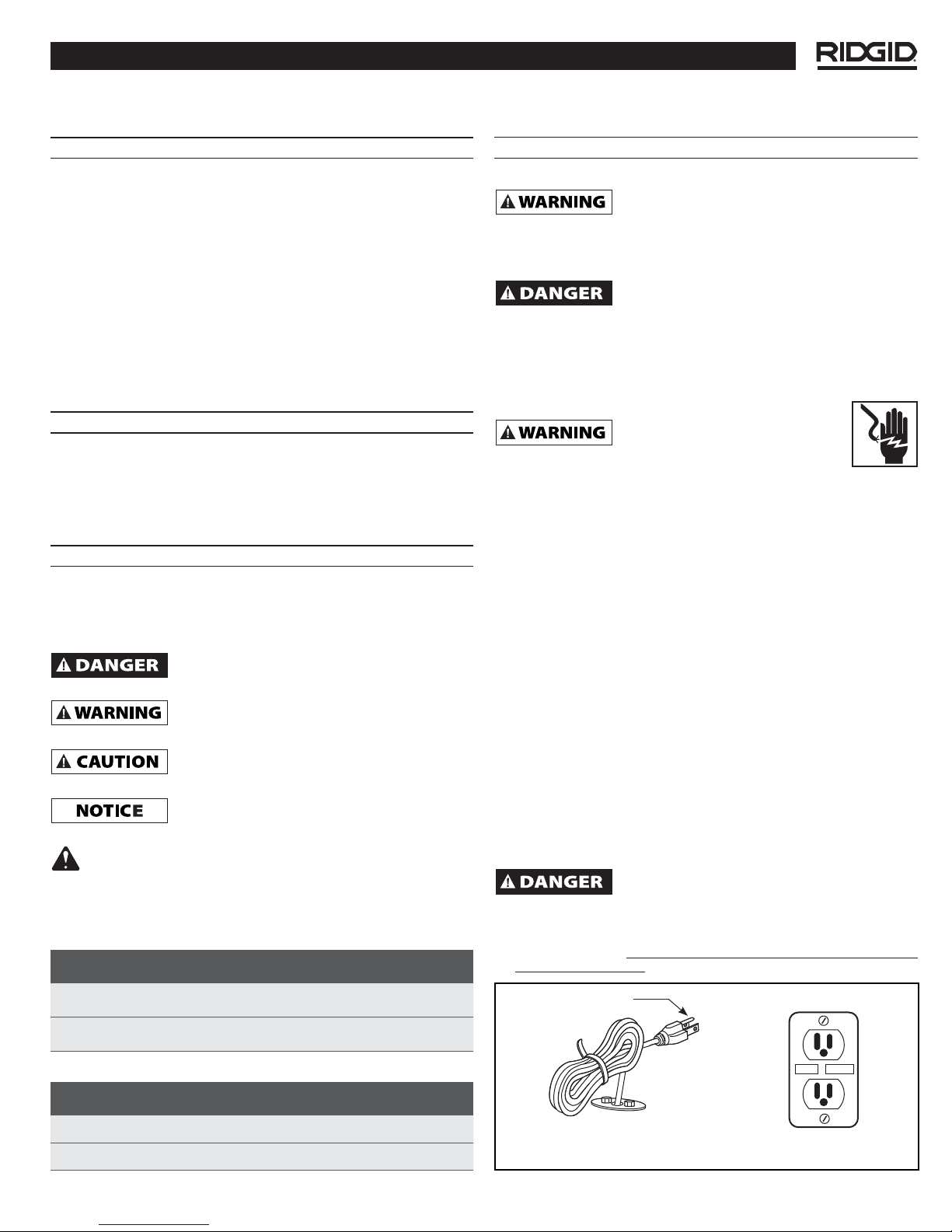
GROUNDING
BLADE
Figure 1
Ridge Tool Company
POWER CORD
GROUNDED OUTLET
RESET
TEST
353502-005 7/11
Model RSS-1000 – Operating Instructions and Parts Manual
GENERAL SAFETY INFORMATION (CONTINUED)
• Stay alert, watch what you are doing, and use common sense
when installing this pump. Do NOT attempt to install this
pump while tired or under the influence of drugs, alcohol or
medications. A moment of inattention MAY result in serious
personal injury.
• Dress properly. Do NOT wear loose clothing or jewelry.
Contain long hair. Keep your hair, clothing, and gloves away
from moving parts. Loose clothes, jewelry, or long hair
CAN be caught in moving parts.
• Do NOT overreach. Keep proper footing and balance at all
times. Proper footing and balance enables better control in
unexpected situations.
• Use safety equipment. Always wear eye protection. Dust
mask, non-skid safety shoes and hard hat MUST be used for
appropriate conditions.
• This pump MUST only be used to pump clear water. This pump
is NOT designed to handle effl uent, salt water, brine, laundry
discharge or any other application which MAY contain caustic
chemicals and/or foreign materials. Pump damage MAY occur
if used in these applications and WILL void warranty.
SERVICE
BACK-UP PUMP BATTERY REQUIREMENTS
1. Use only a new fully charged 12 volt deep cycle battery.
Electrolyte level must be checked and maintained in
accordance with manufacturer’s guidelines.
2. Battery sizes that will fi t into the battery box are 24C,
24VCM, 27C, 27CM and 27F.
3. Battery recharge time will be different at each installation.
Under normal conditions it will take two to four days to bring
a deep cycle battery back to full charge after it has been
discharged. If electrical power to the house is lost more than
once a week, consider keeping a spare, fully-charged battery
to replace an exhausted battery for the standby sump pump.
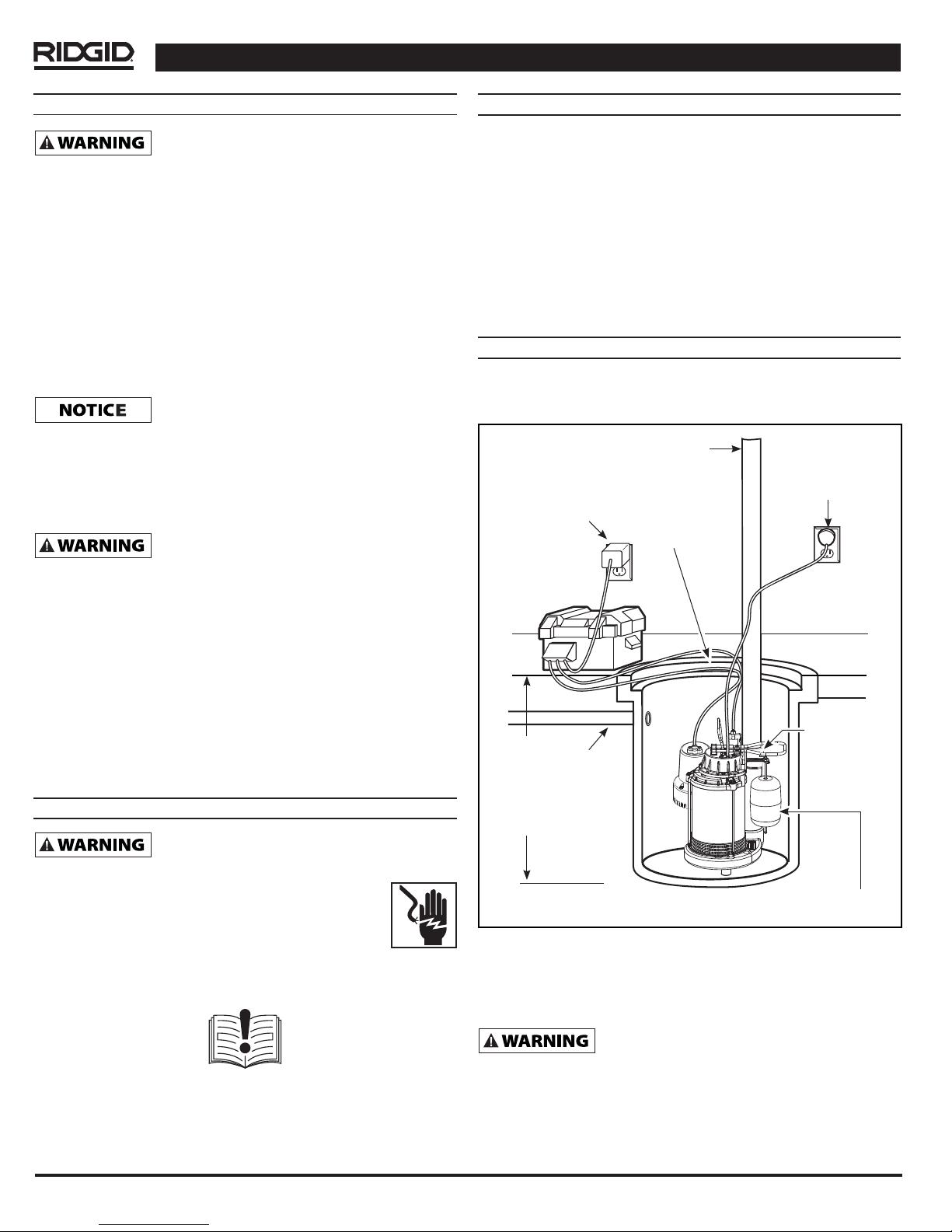
SYSTEM INSTALLATION
1. Install system in a sump pit that is 14 inches in diameter or
greater. Construct sump pit of tile, concrete, steel, or plastic.
Position primary pump switch AWAY from any inlets (Figure 2).
DISCHARGE PIPE
GROUNDED
GROUNDED
(GFCI) OUTLET
14 INCH
DIAMETER MIN.
(GFCI) OUTLET
• Disconnect power and release all pressure within the
system before servicing any component.
• Drain all liquids from system before servicing.
• Periodically inspect pump and system components,
checking for weak and/or worn hoses. Insure all
connections are secure.
• Provide a means of pressure relief in the case of an
obstructed discharge line.
• When servicing a pump, use only identical replacement
parts. Follow instructions in the Maintenance Section. Use of
unauthorized parts or failure to follow maintenance instructions
MAY create a risk of electrical shock or injury and MAY void the
warranty.
SPECIFIC SAFETY INFORMATION
• Risk of electric shock. This pump is supplied with
a grounding-type plug. To reduce risk of electric
shock be certain that it is connected only to a
properly grounded, grounding-type receptacle.
For your own safety, before assembling and
operating this unit, read this operators manual
carefully and completely. Learn the operation, application,
and potential hazards peculiar to this unit.
Call the Ridge Tool Company, Technical Service Department at
1-877-9RIDGID (1-877-974-3443) if you have any questions.
CHECK VALVE
(NOT VISIBLE)
INLET
PIPE
24 INCH MIN.
Figure 2
FLOAT SWITCH
2. The unit should be located and rest on a solid, level
foundation. Do not place pump directly on clay, earth,
gravel or sandy surface. These surfaces contain small
stones, gravel, sand, etc. that may clog or damage the
pump and cause pump failure.
Flood risk. If fl exible discharge hose is used, make
movement. Failure to secure pump could allow pump movement and
prevent pump from starting or stopping.
sure pump is secured in sump pit to prevent
3. Using PVC cement and primer, connect 1-1/4 inch or
1-1/2 inch rigid pipe to the system's discharge fi tting.
2
Ridge Tool Company
Model RSS-1000 – Operating Instructions and Parts Manual
SYSTEM INSTALLATION (CONTINUED)
Support pump and piping when assembling
and after installation. Failure to do so COULD
cause piping to break, pump to fail, etc. which COULD result in
property damage and/or personal injury.
4. Place battery in box. Attach red cable from battery box
control panel to positive battery terminal. Attach black
cable to the negative terminal. Place cover on battery box.
If cables are reversed, damage to the
control box or battery COULD result and
WILL void the warranty.
5. Place battery box within six feet of the sump and a
120 VAC separately fused outlet. The outlet must be
protected by a ground fault circuit interrupter (GFCI).
The area must also be clean, dry, and well-ventilated.
6. Plug the fl oat switch, pump, and charger into the control
box. The connections are marked on the control box.
7. Protect electrical cords from sharp objects, hot surfaces,
oil and chemicals. Avoid kinking the cord, and replace
damaged cords immediately.
8. A sump pit cover must be installed to prevent debris
from clogging or damaging the pump.
SYSTEM OPERATION
PRIMARY PUMP
For detailed operation instructions of the primary pump
for this system, please refer to the Installation manual, and
Warranty and Service parts sheet provided.
BACK-UP PUMP
Always disconnect the power source before
attempting to install, service, relocate
or maintain the pump. NEVER touch sump pump, pump
motor, water or discharge piping when pump is connected to
electrical power. NEVER handle a pump or pump motor with
wet hands or when standing on wet or damp surface or in
water. Fatal electrical shock COULD occur.
1. Test Backup Pump operation by fi lling the sump with
water while the main pump is unplugged.
2. After installation, the standby pump will start when the
water level rises above the depth that the primary pump
should start.
3. In addition, the control box has a time delay which keeps
the pump from repeated, short cycles when it shuts off.
This time delay feature will allow the pump to run 20-25
seconds after the switch reaches the off position.
4. The control box contains a multi-colored indicator light.
When AC power is present, the light will indicate the charging
state, and not refl ect actual battery voltage, particularly with
a defective battery. In order for the indicator light to provide
an accurate reading, steps “a” through “d” must be followed.
a. Unplug main AC pump and the charger-a power off
alert tone will sound for 30 seconds.
b. Lift and release the fl oat switch to activate the
standby pump.
c. When the pump stops, read the test light:
Green: Indicates battery is charged.
Yellow: Voltage is low, indicating battery is partially
charged.
Red: Battery is completely discharged or
defective.
d. Plug in charger and main AC pump.
When AC power is out, and when pump has been
running, the light will indicate battery status.
5. A chirping sound from the control box will accompany
the red light, indicating that the battery may require
attention or replacement. Voltage is only an indicator of
battery condition and may not refl ect the true condition
of the battery. See Maintenance for instruction on
assessing battery condition.
6. A single thirty-second tone will sound when power to the
system is interrupted. The unit will reset automatically
when power is restored. A three-second tone will sound
every time the pump starts.
MAINTENANCE INSTRUCTIONS
PRIMARY PUMP
For detailed maintenance instructions of the primary pump
for this system, please refer to the Installation manual, and
Warranty and Service parts sheet provided.
BACK-UP PUMP
Always disconnect the power source before
attempting to install, service, relocate or maintain
the pump. NEVER touch sump pump, pump motor, water or discharge
piping when pump is connected to electrical power. NEVER handle
a pump or pump motor with wet hands or when standing on wet or
damp surface or in water. Fatal electrical shock could occur.
1. Once a month, check battery condition.
2. Unplug the wall charger.
3. For batteries with top caps that can be removed, the
electrolyte level should be checked and fi lled to
manufacturer’s specifi cations. The charge for each cell
should be checked with a hydrometer. A specifi c gravity
of 1.265 indicates the battery is at full charge. If the
specifi c gravity of any of the cells varies more than .050,
the battery should be replaced.
NOTE: An inexpensive hydrometer can be purchased at an
automotive parts dealer.
4. Inspect the terminals and clamps for corrosion and
tightness. Clean and tighten as required.
5. Unplug the main pump and fi ll sump with water until
back up pump turns on. Repeat process two times to be
sure pump is operating normally.
6. If pump operates normally, plug charger into wall
outlet, turn on main pump. If pump fails to operate
normally, see Troubleshooting guide and correct
problem. Repeat step 5.
PART REPLACEMENT SCHEDULE
Failure to follow replacement schedule
WILL void warranty.
1. Primary Pump: Replace Float every two years. Use
RIDGID catalog #90167.
Ridge Tool Company
3

Model RSS-1000 – Operating Instructions and Parts Manual
MAINTENANCE INSTRUCTIONS (CONTINUED)
2. Back-up Pump: Replace the pump every five years. Use
RIDGID catalog #90152.
3. Back-up Pump: Replace control and charger every five
years. Use RIDGID catalog #90147 for the control and
SERVICE AND REPAIR
Service and repair work on this pump must
be performed by qualified repair personnel.
Pump should be taken to a RIDGID Independent Authorized
Service Center or returned to the factory. All repairs made
by RIDGID service facilities are warranted against defects in
material and workmanship.
90142 for the charger.
4. Back-up Pump: Replace the battery every three years.
When servicing this pump, only identical
RIDGID replacement parts should be used.
Failure to follow these steps may create a risk of flooding,
property damage, fatal electrical shock, or other serious injury.
TROUBLESHOOTING CHART – Primary Pump
For detailed troubleshooting information of the primary pump for this system, please refer to the Installation manual, and
Warranty and Service parts sheet provided.
TROUBLESHOOTING CHART – Back-up Pump
SYMPTOM POSSIBLE CAUSE(S) CORRECTIVE ACTION
Pump will not
run
1. Connections not secure
2. Low or defective battery
3. Float switch obstruction
4. Defective or blown fuse
1. Check all connections.
2. Check battery and replace if low or defective.
3. Make sure nothing is interfering with the operation of the
switch.
4. Check internal fuse located inside the control box. Pull the
charger from the wall outlet and remove. If the fuse is blown,
replace it with a 15 amp automotive type fuse.
Motor hums
but pump
won’t run
Pump runs
but pumps
very little or no
water
Pump cycles
too frequently
1. Defective battery
2. Obstructed impeller
1. Check valve missing or improperly
installed
2. Obstruction in discharge pipe
3. Pump not rotated 30˚
4. Pump air locked
5. Discharge pipe length and / or
height exceeds capacity of pump
6. Low or defective battery
1. Main check valve located between
the discharge of the primary pump
and the Back-up Sump Pump
tee fi tting or the Back-up Sump
Pump fl apper valve not installed or
working properly
1. Check battery and replace if low or defective.
2. Unplug pump and check to see if impeller is free to turn. If
impeller is locked, remove the 4 screws on the bottom of the
pump to release the housing around the impeller. Remove
the obstruction. Reassemble pump and reconnect.
1. Check to make sure a check valve is installed and
functioning between primary pump discharge and Standby
Sump Pump tee fi tting.
2. Check for obstruction and clear if necessary.
3. Check that pump is rotated 30˚ in tee fi tting.
4. The impeller housing has a small hole on its side. This
hole must be open for the pump to prime. With the pump
unplugged, remove the 4 screws on the bottom of the pump
to release the housing around the impeller. Clean out the
hole and replace cover.
5. If discharge is too high, a separate line may be required with
a lower discharge height.
6. Check battery and replace if low or defective.
1. Install check valve or repair as required.
4
Ridge Tool Company
Model RSS-1000 – Operating Instructions and Parts Manual
RSS-1000 — Preassembled Sump System
Serial No.
If you have any questions regarding the
service or repair of this pump, call or
write to:
RIDGID Water Systems
Attn: Customer Service Department
101 Production Drive
Harrison, Ohio 45030
csridgid@waynewatersystems.com
For name and address of your nearest
Independent Authorized Service Center,
contact the Ridge Tool Company at
http://www.RIDGID.com
For Customer Service,
call 1-877-9RIDGID.
Record Serial Number From Product Decal Below:
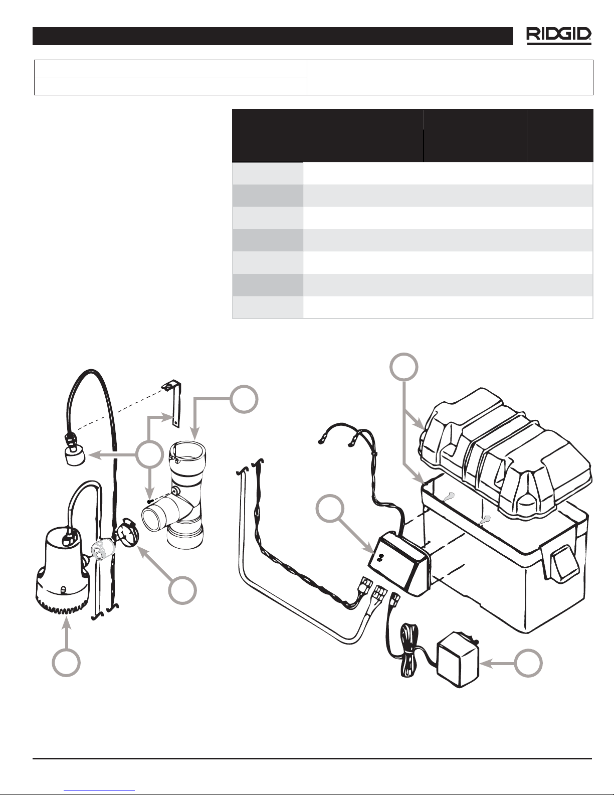
Reference
Number Description
1
2
3
4
5
6
7
Float Switch / Bracket Kit 31833
Tee Fitting 90132
Battery Box 90137
Charger 90142
Control Box 90147
Pump 90152
Clamp Hose 90162
RSS-1000
Cat. No.
31633
Quantity
1
1
1
1
1
1
1
1
3
2
5
7
6
Ridge Tool Company
4
5

Model RSS-1000 – Operating Instructions and Parts Manual
NOTES
6
Ridge Tool Company
 Loading...