

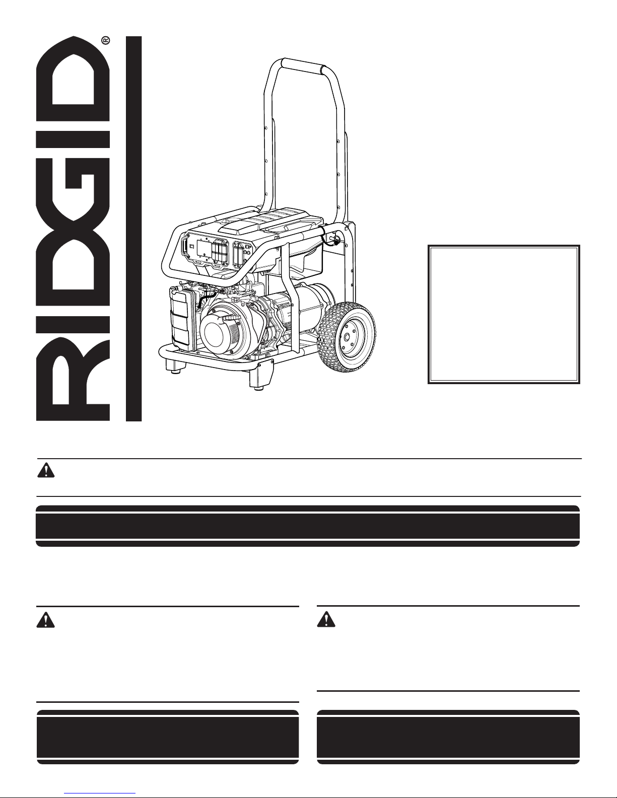
RIDGID RD6800, RD68011, RDCA6800 Operator's Manual
OPERATOR’S MANUAL
Manuel de l’opérateur
Manual del operador
PORTABLE GENERATOR
Groupe portable
Generador portàtil
RD6800/RD68011/RDCA6800
Series / Série / Serie
To register your RIDGID
product, please visit:
http://register.RIDGID.com
Pour enregistrer votre
produit de RIDGID,
s’il vous plaît la visite:
http://register.RIDGID.com
Para registrar su producto
de RIDGID, por favor visita:
http://register.RIDGID.com
NEUTRAL BONDED TO FRAME
(CONNECTEUR NEUTRE RELIÉ AU CADRE, PUNTO NEUTRO CONECTADO AL MARCO)
Your generator has been engineered and manufactured to our high standard for dependability, ease of operation, and operator
safety. When properly cared for, it will give you years of rugged, trouble-free performance.
WARNING: To reduce the risk of injury, the user must read and understand the operator’s manual before using this
product. If you do not understand the warnings and instructions in the operator’s manual, do not use this product.
SAVE THIS MANUAL FOR FUTURE REFERENCE
Ce groupe portable a été conçu et fabriqué conformément à
nos strictes normes de fiabilité, simplicité d’emploi et sécurité
d’utilisation. Correctement entretenu, cet outil vous donnera des
années de fonctionnement robuste et sans problème.
AVERTISSEMENT :
Pour réduire les risques de blessures, l’utilisateur doit
lire et veiller à bien comprendre le manuel d’utilisation
avant d’employer ce produit. Si tous les avertissements
et toutes les consignes de sécurités et instructions du
manuel d’utilisation ne sont pas bien compris, ne pas
utiliser ce produit.
Su generador portàtil diseñado y fabricado de conformidad con
nuestras estrictas normas para brindar fiabilidad, facilidad de uso
y seguridad para el operador. Con el debido cuidado, le brindará
muchos años de sólido funcionamiento y sin problemas.
ADVERTENCIA:
Para reducir el riesgo de lesiones, el usuario debe leer y
comprender el manual del operador antes de usar este
producto. Guarde este manual del operador y estúdielo
frecuentemente para lograr un funcionamiento seguro y
continuo de este producto.
CONSERVER CE MANUEL POUR
FUTURE RÉFÉRENCE
GUARDE ESTE MANUAL PARA
FUTURAS CONSULTAS

See this fold-out section for all of the figures referenced
in the operator’s manual.
Consulter l’encart à volets afin d’examiner toutes les
figures mentionnées dans le manuel d’utilisation.
Consulte esta sección desplegable para ver todas las
figuras a las que se hace referencia en el manual del
operador.
ii
ENGINE SWITCH
OFF
CIRCUIT BREAKER
OFF
ENGINE SWITCH
ENGINE SWITCH
OFF
CIRCUIT BREAKER
Fig. 3
Fig. 2Fig. 1
A
b
A - Reset button (bouton de réinitialisation,
botón de reajuste)
B - Test button (bouton de test, botón de
prueba)
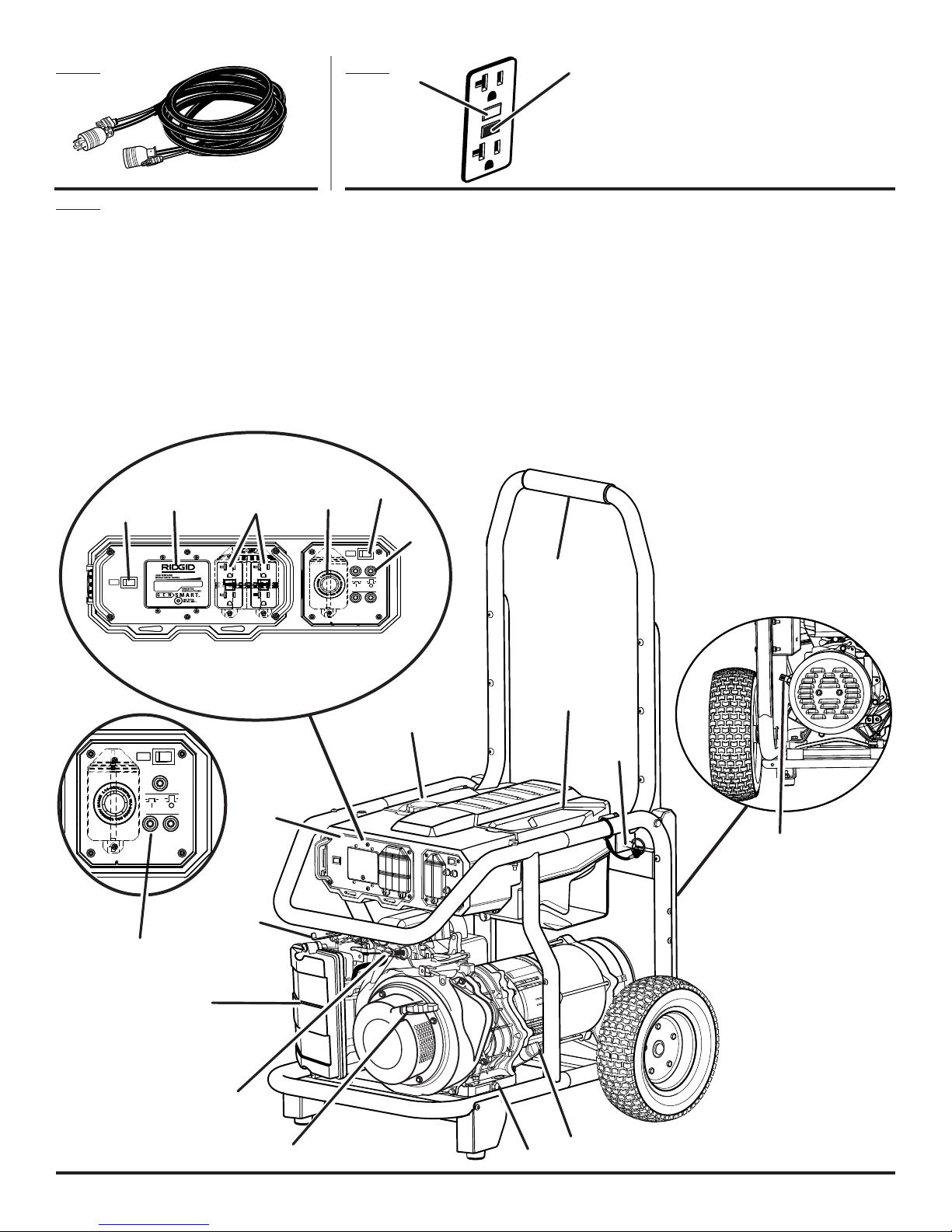
A - Recoil starter grip (poignée du démarreur à
rappel, mango del arrancador retráctil)
B - Air filter (filtre à air, filtro de aire)
C - Choke lever (levier d’étrangleur, palanca del
anegador)
D - Removable control panel (panneau de
commande amovible, panel de control en
distintas)
E - Fuel cap (bouchon de carburant, tapa del
tanque)
F - Off switch (interrupteurs de moteur,
interruptor del motor)
G
F
H
G - GenSmart™ monitoring system (système
de surveillance GenSmart™, sistema de
monitoreo GenSmart™)
H - 120 volt AC GFCI 20 amp receptacles (prises
120 V C.A. GFCI 20 A, 120 V de CA GFCI 20
A receptáculos)
I - 120 V / 240 V AC 30 amp receptacle (prise
120 V / 240 V C.A. 30 A, 120 V / 240 V de CA
30 A receptáculo)
J - AC circuit breaker (disjoncteur de C.A.,
disyuntor de circuito de CA)
K - Handle (poignée, mango)
I
F
J
K
L- Fuel tank (réservoir de carburant, tanque de
combustible)
M
- AC circuit breaker model RD68011/model
RDCA6800 (disjoncteur de C.A. model
RD68011/model RDCA6800, disyuntor
de circuito de CA model RD68011/model
RDCA6800)
N
- Ground terminal (borne de terre, terminal de
conexión a tierra)
O - Oil cap/dipstick (bouchon/jauge d’huile,
tapa de relleno de aceite/varilla medidora de
aceite)
P - Oil drainage bolt (vis de vidange d’huile,
perno de drenaje de aceite)
Q - Handle lock pin (goupille de blocage de la
poignée, pasador de seguro del mango)
R - Fuel valve (robinet de carburant, válvula de
combustible)
L
e
Q
d
N
c
M
b
R
A
o
p
iii
10
9
2
3
1
4
7
6
5
8
11
6
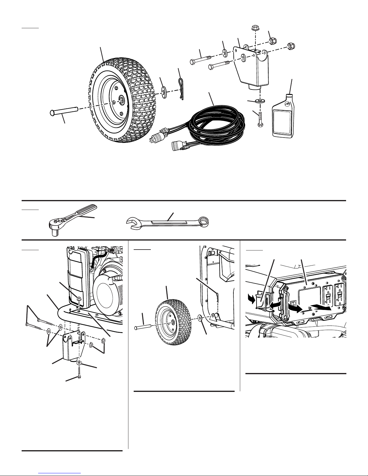
Fig. 4
1 - Axle (essieu, eje)
2 - Wheel (roue, rueda)
3 - Flat washer (rondelle plate, arandela plana)
4 - Hitch pin (axe de blocage, pasador del
enganche)
5 - Screw, 2 in. (vis, 2 po; tornillo, 2 pulg.)
6 - Flat washer (rondelle plate, arandela plana)
Fig. 5
A
Fig. 6
c
e
A
7 - Leg with rubber foot (pied avec patin en
caoutchouc, pata con pie de goma)
8 - Nut (écrou, tuerca)
9 - Control panel cord, 25 ft. (cordon de
panneau de commande 25 pi, cordón de
panel de control 25 pies)
b
A - Socket wrench (clé à douille, llave de casquillo)
B - Combination wrench (clé mixte, llave de combinación)
Fig. 7
b
A
d
10 - Engine lubricant (lubrifiant de moteur,
lubricante para motor)
11 - Screw, 1 in. (vis, 1 po; tornillo, 1 pulg.)
Fig. 8
A
b
G
b
d
c
b
F
A - Screw, 2 in. (vis, 2 po; tornillo, 2 pulg.)
B - Flat washer (rondelle plate, arandela plana)
C - Lock nut (écrou de blocage, tuerca de
seguridad)
D - Leg with rubber foot (pied avec patin en
caoutchouc, pata con pie de goma)
E - Frame (cadre, armazón)
F - Screw, 1 in. (vis, 1 po; tornillo, 1 pulg.)
G - Frame crossbar (barre stabilisatrice du cadre
travesaño del bastidor)
c
A - Axle (essieu, eje)
B - Wheel (roue, rueda)
C - Mount bracket (support de montage, soporte
D - Hitch pin (goupille de sûreté, pasador de
de montaje)
enganche)
iv
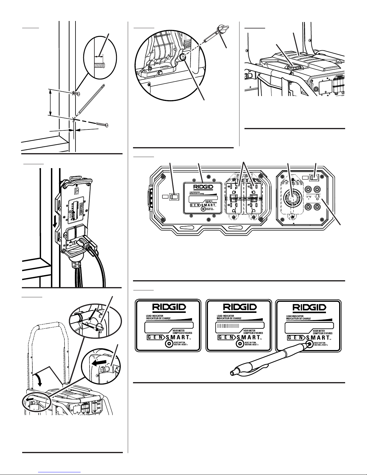
A - Latch (loquet, pestillo)
B - Removable control panel (panneau de
commande amovible, panel de control en
distintas)
ENGINE SWITCH
OFF
CIRCUIT BREAKER
OFF
ENGINE SWITCH
ENGINE SWITCH
4-1/4 in.
5/8 in.
1/4 in.
Fig. 9
READ AND UNDERST
0HRS
PRESS AND HOLD RE
100 HRS
0 HRS
Fig. 12
Fig. 13
b
A
A
Fig. 10
b
A - Oil cap/dipstick (bouchon/ jauge d’huile,
tapa de relleno de aceite/varilla medidora de
aceite)
B - Oil fill hole (orifice de remplissage d’huile,
agujero de llenado de aceite)
Fig. 14
A - Off switch (interrupteur de moteur, interruptor
del motor)
B - GenSmart™ monitoring system (système
de surveillance GenSmart™, sistema de
monitoreo GenSmart™)
A
b
A - Fuel cap (bouchon de carburant, tapa del
tanque de combustible)
B - Fuel tank (réservoir de carburant, tanque de
combustible)
c
d
A
C - 120 volt AC 20 amp receptacles (prises 120 V
C.A. 20 A, 120 V de CA 20 A receptáculos)
D - 240 volt AC 30 amp receptacle (prise 240 V
C.A. 30 A, 240 V de CA 30 A receptáculo)
E - AC circuit breaker (disjoncteur de C.A.,
disyuntor de circuito de CA)
e
Fig. 11
c
b
A
A - Handle (poignée, mango)
B - Handle release knob (relâchez le bouton de
poignée, perilla de afloje del mango)
C - Handle lock pin (goupille de blocage de la
poignée, pasador de seguro del mango)
Fig. 15
v
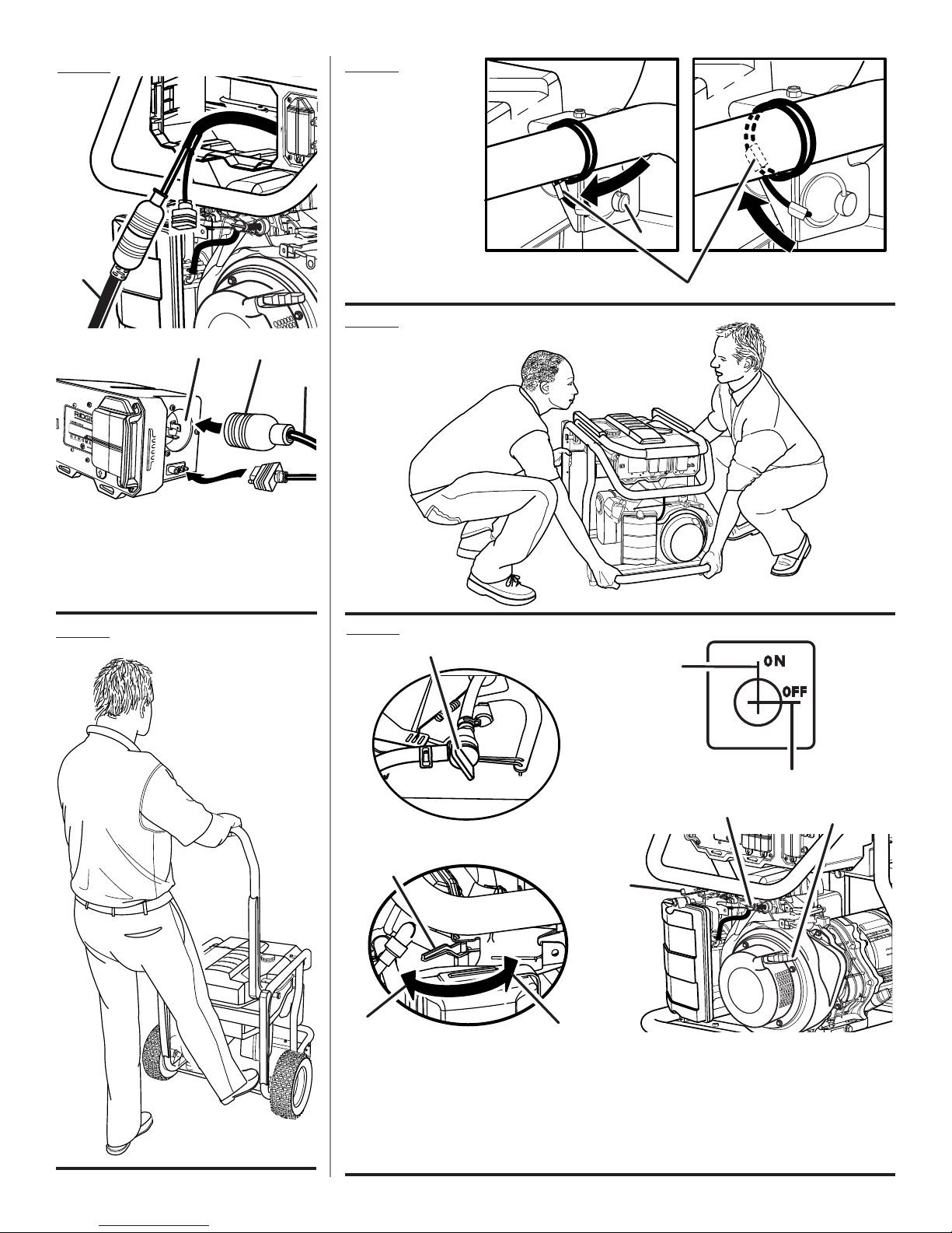
Fig. 16
A
Fig. 18
A - Handle lock pin
(goupille de blocage
de la poignée,
pasador de seguro
del mango)
B - Joined area (partie
jointe, área acoplada)
Fig. 19
A
b
c
b
A
A - Control panel cord (cordon de panneau de
commande, cordón de panel de control)
B - Twist-lock plug (prise à verrouillage, enchufe
de bloqueo de giro)
C - Twist-lock receptacle (prise à verrouillage par
rotation, receptáculo de fijación)
Fig. 17
Fig. 20
A
c
b
A
G
d
d
F
A - Fuel valve (robinet de carburant, válvula de combustible)
B - Off (arret, apagado)
C - On (marche, encendido)
D - Choke lever (levier de volet de départ, palanca del anegador)
E - Start position (position de démarrage, posición de arranque)
F - Run position (position de marche, posición de functionamiento)
G - Recoil starter grip (manchon en lanceur à rappel, agarradera del arranque retráctil)
e
vi
ENGINE SWITCH
OFF
CIRCUIT BREAKER
OFF
ENGINE SWITCH
Fig. 21
OFF
A
A
A - Off switch (interrupteur arrêt de moteur,
interruptor encendido/apagado del motor)
Fig. 24
A
b
Fig. 27
Fig. 22
c
A
d
b
A - Screws (vis, tornillos)
B - Air filter cover (couvercle du filtre à air, tapa del
filtro de aire)
C - Filter element (élément du filtre, elemento
de filtro)
D - Air filter unit (unité de filtre à air, unidad del
filtro de aire)
Fig. 23
A - Spark plug (bougie, bujía)
B - Spark plug cap (capuchon de bougie, tapa de
la bujía)
Fig. 25
Fig. 26
e
b
d
A
A - Carburetor drain screw (vis de vidange
du carburateur, tornillo de drenaje del
carburador
Fig. 28
b
A
A - Fuel line (conduites de carburant ,conducto
de combustible)
B - Fuel filter (filtre à carburant, filtro de
combustible)
A
b
c
A - Oil cap/dipstick (bouchon/ jauge d’huile,
tapa de relleno de aceite/varilla medidora de
aceite)
B - Oil fill hole (orifice de remplissage d’huile,
agujero de llenado de aceite)
C - Oil drainage bolt (vis de vidange d’huile,
perno de drenaje de aceite)
A
c
A - Fuel line (conduite de carburant, conducto de
combustible)
B - Petcock (robinet de carburant, llave de
purga)
C - Fuel valve (robinet de carburant, válvula de
combustible)
D - Off (arret, apagado)
E - On (marche, encendido)
vii
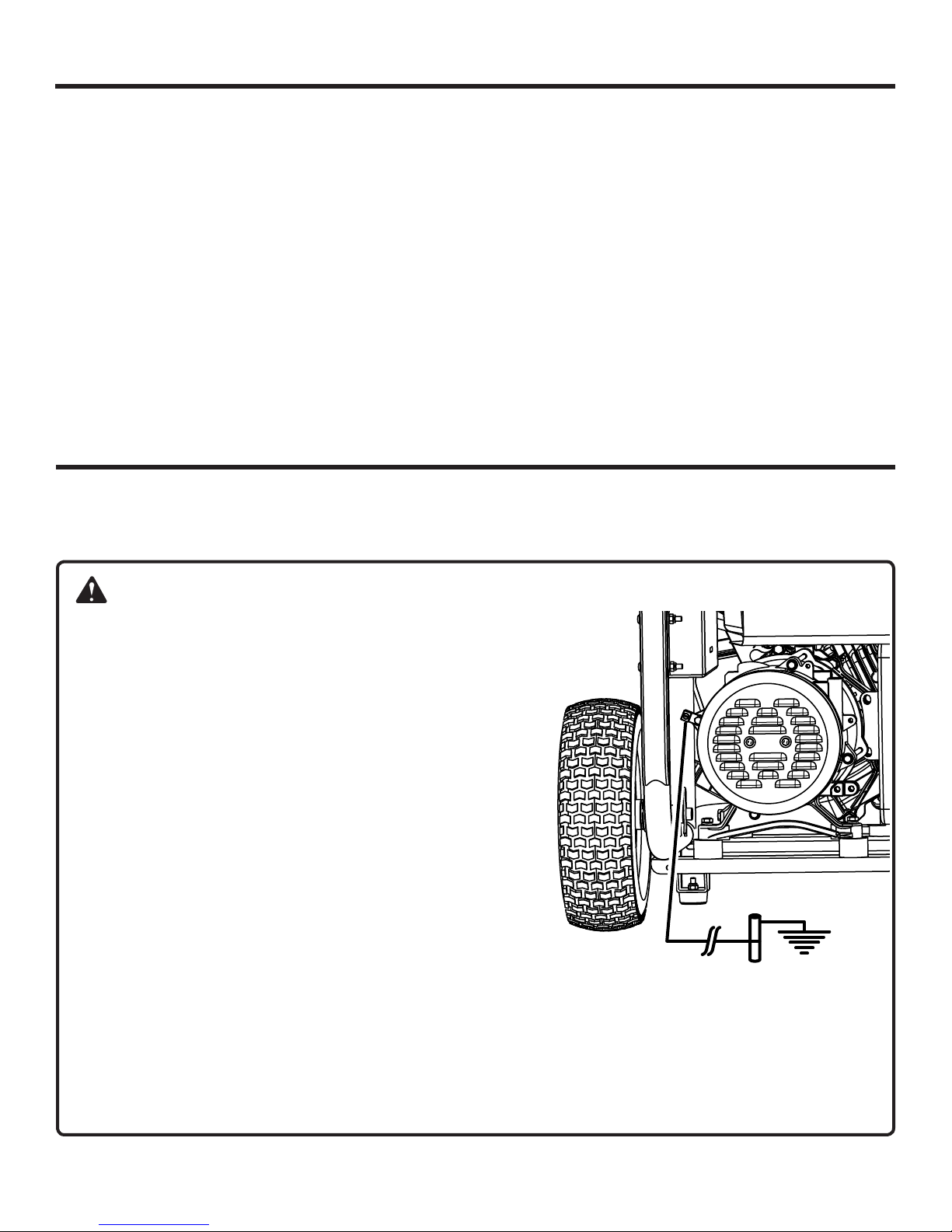
TABLE OF CONTENTS
Introduction ..................................................................................................................................................................... 2
Important Safety Instructions .......................................................................................................................................3-4
Specific Safety Rules ...................................................................................................................................................... 4
Symbols .......................................................................................................................................................................5-7
Electrical .......................................................................................................................................................................7-9
Features ...................................................................................................................................................................10-11
Assembly ..................................................................................................................................................................11-12
Operation ..................................................................................................................................................................13-15
Maintenance .............................................................................................................................................................16-18
Troubleshooting ............................................................................................................................................................. 19
Warranty ...................................................................................................................................................................20-21
Parts Ordering / Service ...................................................................................................................................Back Page
INTRODUCTION
This product has many features for making its use more pleasant and enjoyable. Safety, performance, and dependability
have been given top priority in the design of this product, making it easy to maintain and operate.
DANGER:
GROUNDING THE GENERATOR
To reduce the risk of shock or electrocution, generator must be
properly grounded. The nut and ground terminal on the frame
must always be used to connect the generator to a suitable
ground source. The ground path should be made with #8 size
wire. Connect the terminal of the ground wire between the lock
washer and the nut, and tighten the nut fully. Connect the other
end of the wire securely to a suitable ground source.
The National Electric Code contains several practical ways in
which to establish a good ground source. If a steel or iron rod is
used, it should be at least 5/8 in. diameter, and if a nonferrous
rod is used, it should be at least 1/2 in. diameter and be listed as
material for grounding. Drive the rod or pipe to a depth of 8 ft. If
a rock bottom is encountered less than 4 ft. down, bury the rod
or pipe in a trench.
All electrical tools and appliances operated from this generator
must be properly grounded by use of a third wire or be “Double
Insulated.”
It is recommended to:
1. Use electrical devices with 3-prong grounded plugs.
2. Use an extension cord with a 3-pole receptacle and a 3-prong plug at opposite ends to ensure continuity of the
ground protection from the generator to the appliance.
Check and adhere to all applicable federal, state, and local regulations relating to grounding specifications. Consult a
qualified electrician or service personnel if the grounding instructions are not completely understood or if in doubt as
to whether the generator is properly grounded.
2 — English
IMPORTANT SAFETY INSTRUCTIONS
Never start or run the engine inside a closed or partially
DANGER:
Carbon Monoxide. Using a generator indoors CAN
KILL YOU IN MINUTES.
Generator exhaust contains high levels of carbon
monoxide (CO), a poisonous gas you cannot see or
smell. If you can smell the generator exhaust, you
are breathing CO. But even if you cannot smell the
exhaust, you could be breathing CO.
Never use a generator inside homes, garages,
crawlspaces, or other partly enclosed areas.
Deadly levels of carbon monoxide can build up
in these areas. Using a fan or opening windows
and doors does NOT supply enough fresh air.
ONLY use a generator outdoors and far away
from open windows, doors, and vents. These
openings can pull in generator exhaust.
Even when you use a generator correctly, CO may
leak into the home. ALWAYS use a battery-powered
or battery-backup CO alarm in the home.
If you start to feel sick, dizzy, or weak after the
generator has been running, move to fresh air
RIGHT AWAY. See a doctor. You could have carbon
monoxide poisoning.
WARNING:
Read and understand all instructions. Failure
to follow all instructions listed below may result
in electrocution, fire, and/or carbon monoxide
poisoning, which will cause death or serious
injury.
WARNING:
National Electric Code requires generator to be
grounded to an approved earth ground. Before
using the ground terminal, consult a qualified
electrician, electrical inspector, or local agency
having jurisdiction for local codes or ordinances
that apply to the intended use of the generator.
SAVE THESE INSTRUCTIONS
This manual contains important instructions for this product
that should be followed during installation and maintenance
of the generator.
Do not connect to a building’s electrical system unless
the generator and transfer switch have been properly
installed and the electrical output has been verified by a
qualified electrician.
Do not allow children or untrained individuals to use this
unit.
enclosed area. Breathing exhaust fumes will kill you.
Always wear eye protection with side shields marked to
comply with ANSI Z87.1 as well as hearing protection
when operating this equipment.
Keep all bystanders, children, and pets at least 10 feet
away.
Wear sturdy and dry shoes or boots. Do not operate while
barefoot.
Do not operate generator when you are tired or under the
influence of drugs, alcohol, or medication.
Keep all parts of your body away from any moving parts
and all hot surfaces of the unit.
Do not touch bare wire or receptacles.
Do not use generator with electrical cords which are worn,
frayed, bare, or otherwise damaged.
Before storing, allow the engine to cool and drain fuel
from the unit.
Do not operate or store the generator in rain, snow, or
wet weather.
Store the generator in a well-ventilated area with the
fuel tank empty. Fuel should not be stored near the
generator.
Empty fuel tank, close fuel valve, and restrain the unit
from moving before transporting in a vehicle.
Allow engine to cool for five minutes before refueling.
To reduce the risk of fire and burn injury, handle fuel with
care. It is highly flammable.
Do not smoke while handling fuel.
Store fuel in a container approved for gasoline.
Position the unit on level ground, stop engine, and allow
to cool before refueling.
Loosen fuel cap slowly to release pressure and to keep
fuel from escaping around the cap.
Tighten the fuel cap securely after refueling.
Wipe spilled fuel from the unit.
Never attempt to burn off spilled fuel under any circum-
stances.
Generators vibrate in normal use. During and after the
use of the generator, inspect the generator as well as
extension cords and power supply cords connected to
it for damage resulting from vibration. Have damaged
items repaired or replaced as necessary. Do not use plugs
or cords that show signs of damage such as broken or
cracked insulation or damaged blades.
For power outages, permanently installed stationary gen-
erators are better suited for providing back-up power to
the home. Even a properly connected portable generator
can become overloaded. This may result in overheating
or stressing the generator components, possibly leading
to generator failure.
3 — English

IMPORTANT SAFETY INSTRUCTIONS
Use only authorized replacement parts and accessories
and follow instructions in the Maintenance section of this
manual. Use of unauthorized parts or failure to follow
maintenance instructions may create a risk of shock or
injury.
SPECIFIC SAFETY RULES
WARNING:
When this generator is used to supply a building
wiring system: generator must be installed
by a qualified electrician and connected to a
transfer switch as a separately derived system
in accordance with NFPA 70, National Electrical
Code. The generator shall be connected through a
transfer switch that switches all conductors other
than the equipment grounding conductor. The
frame of the generator shall be connected to an
approved grounding electrode. Failure to isolate
the generator from power utility can result in death
or injury to electric utility workers.
Exhaust contains poisonous carbon monoxide, a color-
less, odorless gas. Breathing exhaust can cause loss
of consciousness and can lead to death. If running in a
confined or partially-enclosed area, the air may contain a
dangerous amount of carbon monoxide. To keep exhaust
fumes from building up, always provide adequate ventilation.
Always use a battery-powered carbon monoxide detec-
tor when running the generator. If you begin to feel sick,
dizzy, or weak while using the generator, shut it off and
get to fresh air immediately. See a doctor. You may have
carbon monoxide poisoning.
Place the generator on a flat, stable surface with a slope
of no more than 4°.
Operate outdoors in a well-ventilated, well-lit area isolated
from working areas to avoid noise interference.
Operating the generator in wet conditions could result in
electrocution. Keep the unit dry.
Keep the generator a minimum of 3 feet away from all
types of combustible material.
Do not operate generator near hazardous material.
Do not operate generator at a gas or natural gas filling
station.
Do not touch the muffler or cylinder during or immediately
after use; they are HOT and will cause burn injury.
Maintain the unit per maintenance instructions in this
Operator’s Manual.
Inspect the unit before each use for loose fasteners, fuel
leaks, etc. Replace damaged parts.
This generator has a neutral bonded condition. This
means the neutral conductor is electrically connected to
the frame of the machine.
Do not allow the generator’s gas tank to overflow when
filling. Fill to 1 in. below the top neck of the gasoline tank
to allow for fuel expansion. Do not cover the fuel tank cap
when the engine is running. Covering the fuel tank cap
during use may cause engine failure and/or damage to
the tool.
Do not smoke when filling the generator with gasoline.
Shut down the engine and allow to cool completely before
adding gasoline or lubricant to the generator.
Do not remove the oil dipstick or the fuel tank cap when
the engine is running.
Pay close attention to all safety labels located on the
generator.
Keep children a minimum of 10 feet away from the gen-
erator at all times.
The unit operates best in temperatures between 23°F and
104°F with a relative humidity of 90% or less.
Specific modifications for high-altitude performance are
needed if the generator will always be operated at altitudes above 5,000 feet. Contact your nearest authorized
service center for more information and to have these
modifications performed.
Operating voltage and frequency requirement of all
electronic equipment should be checked prior to plugging them into this generator. Damage may result if the
equipment is not designed to operate within a +/- 10%
voltage variation, and +/- 3 hz frequency variation from
the generator name plate ratings. To reduce the risk of
damage, always have an additional load plugged into the
generator if solid state equipment (such as a television
set) is used. A power line conditioner is recommended
for some solid state applications.
Save these instructions. Refer to them frequently and use
them to instruct others who may use this product. If you
loan someone this product, loan them these instructions
also.
4 — English
SYMBOLS
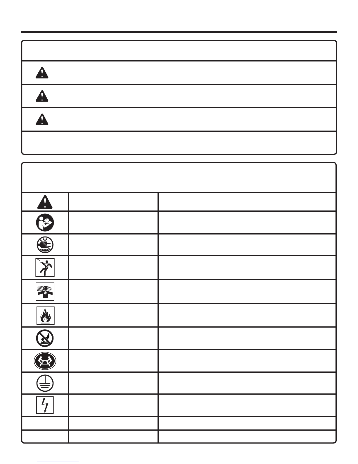
The following signal words and meanings are intended to explain the levels of risk associated with this product.
SYMBOL SIGNAL MEANING
DANGER:
WARNING:
CAUTION:
CAUTION:
Some of the following symbols may be used on this product. Please study them and learn their meaning. Proper
interpretation of these symbols will allow you to operate the product better and safer.
Indicates an imminently hazardous situation, which, if not avoided, will result
in death or serious injury.
Indicates a potentially hazardous situation, which, if not avoided, could result
in death or serious injury.
Indicates a potentially hazardous situation, which, if not avoided, may result in
minor or moderate injury.
(Without Safety Alert Symbol) Indicates a situation that may result in property
damage.
SYMBOL NAME DESIGNATION/EXPLANATION
Safety Alert Indicates a potential personal injury hazard.
Read Operator’s Manual
To reduce the risk of injury, user must read and understand
operator’s manual before using this product.
Wet Conditions Alert Do not expose to rain or use in damp locations.
Electric Shock
Toxic Fumes
Fire/Explosion
Hot Surface
Lifting Hazard
Ground
Electrocution
Failure to use in dry conditions and to observe safe practices can
result in electric shock.
Running generator gives off carbon monoxide, an odorless, colorless, poison gas. Breathing carbon monoxide can cause nausea,
fainting, or death.
Fuel and its vapors are extremely flammable and explosive. Fire
or explosion can cause severe burns or death.
To reduce the risk of injury or damage, avoid contact with any hot
surface.
To reduce the risk of serious injury, avoid attempting to lift the
generator alone.
Consult with local electrician to determine grounding requirements
before operation.
Failure to properly ground generator can result in electrocution,
especially if the generator is equipped with a wheel kit.
V Volts Voltage
A Amperes Current
5 — English
SYMBOLS
DANGER
DANGER
PELIGRO
L’utilisation d’une génératrice à l’intérieur PEUT VOUS
TUER ENQUELQUES MINUTES.
Les génératrices produisent du monoxyde de carbone,
un gaz mortel incolore et inodore.
NE JAMAIS utiliser à l’intérieur d’une maison ou d’un
garage,MÊME SI les portes et les fenêtres sont ouvertes.
Utiliser uniquement À L’EXTÉRIEUR et loin des fenêtres,
des portes et des évents.
Usar un generador en el interior PUEDE MATARLO EN
POCOS MINUTOS.
Los gases de escape del generador contienen monóxido
de carbono. Es un veneno que no puede verse ni olerse.
NUNCA lo use dentro de su hogar o del garaje, INCLUSO
con las puertas y las ventanas abiertas.
Sólo utilícelo AL AIRE LIBRE y lejos de ventanas, puertas
y respiraderos.
Using a generator indoors CAN KILL YOU IN MINUTES.
Generator exhaust contains carbon monoxide. This is a
poison you cannot see or smell.
NEVER use inside a home
or garage, EVEN IF doors
and windows are open.
Only use OUTSIDE and
far away from windows,
doors, and vents.
Some of the following symbols may be used on this product. Please study them and learn their meaning. Proper
interpretation of these symbols will allow you to operate the product better and safer.
SYMBOL NAME DESIGNATION/EXPLANATION
Hz Hertz Frequency (cycles per second)
W Watt Power
hrs Hours Time
gal Gallon Volume
qt Quart Volume
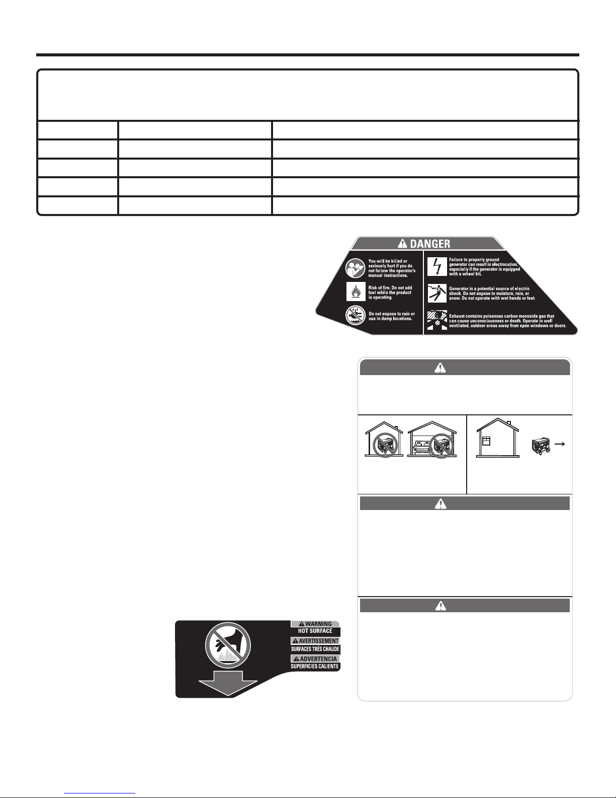
SAFETY LABELS
The information on this page can be found on the generator. For
your safety, please study and understand all of the labels before
starting the generator.
If any of the labels come off the unit or become hard to read,
contact an authorized service center for replacement.
You WILL be KILLED or SERIOUSLY HURT if you do not follow the
Operator’s Manual instructions.
Risk of Fire. Do not add fuel while the product is operating.
Generator is a potential source of electric shock. Do not expose to
moisture, rain, or snow. Do not operate with wet hands or feet.
Exhaust contains poisonous carbon monoxide gas that can cause
unconsciousness or DEATH. Operate in well-ventilated, outdoor
areas away from open windows or doors.
Failure to properly ground generator can result in electrocution,
especially if the generator is equipped with a wheel kit.
Do not expose to rain or use in damp locations.
Using a generator indoors CAN KILL YOU IN MINUTES. Generator
exhaust contains carbon monoxide. This is a poison you cannot
see or smell.
NEVER use inside a home or garage, EVEN IF doors and windows
are open.
Only use OUTSIDE and far away from windows, doors, and vents.
HOT SURFACE WARNING
Do not touch the muffler
or aluminum cylinder of the
engine. They are very HOT
and will cause severe burns.
Don’t put any flammable or
combustible materials in the
direct path of the exhaust.
6 — English
SYMBOLS
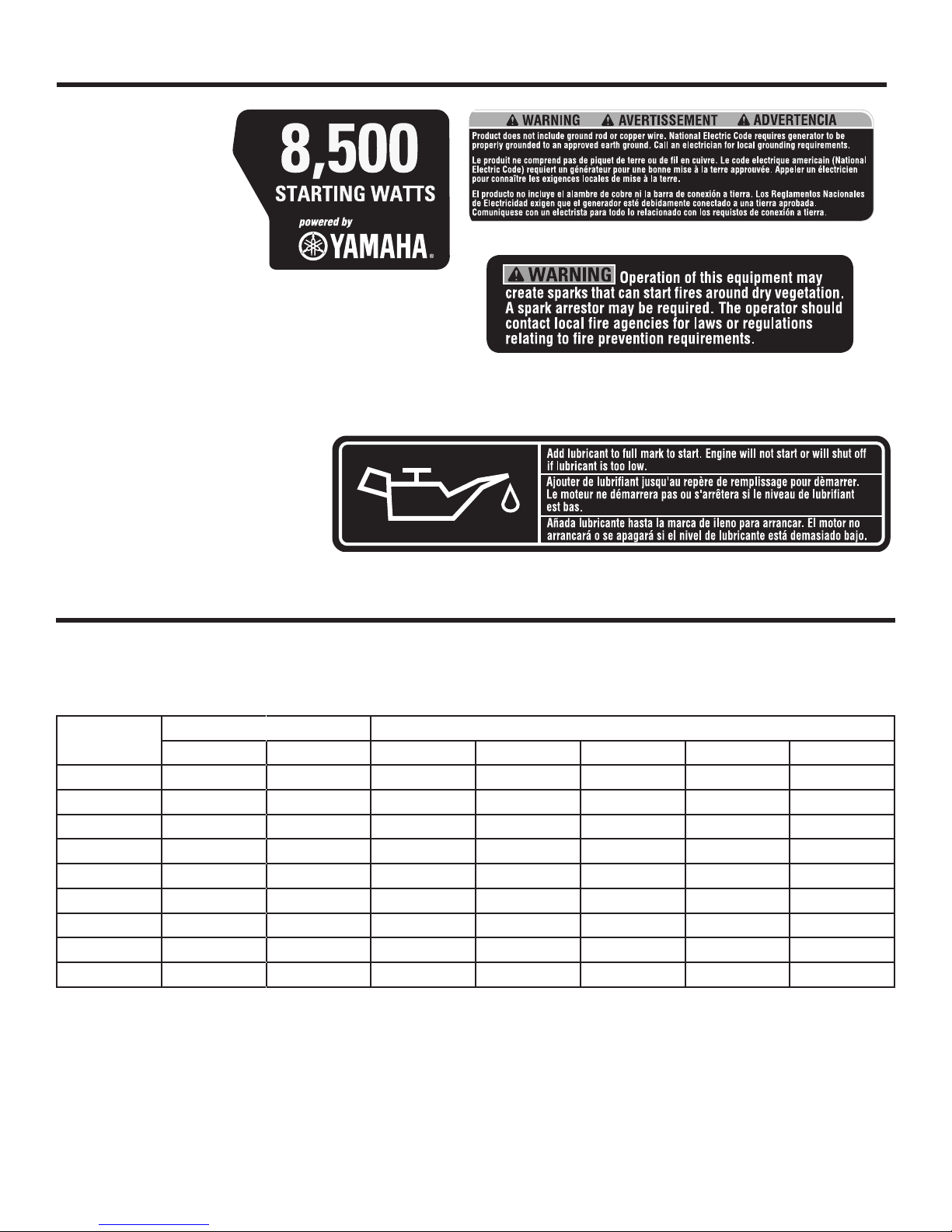
FUEL WARNING
No smoking when filling
with gasoline. Do not
overfill. Full level is 1 in.
below the top of the fuel
neck. Stop the engine
for five minutes before
refueling to avoid the
heat from the muffler
igniting fuel vapors.
ENGINE LUBRICANT WARNING
You must add lubricant before first operating the generator.
The oil reservoir capacity is 1.1 qt. Always check the lubricant level before each operation. The lubricant level should
always register between the hatched areas on the dipstick.
The unit is equipped with a sensor which will automatically
shut off the engine if the lubricant level
falls below a safe limit.
GROUNDING WARNING
National Electric Code requires generator to be grounded to an approved
earth ground.
ELECTRICAL
EXTENSION CORD CABLE SIZE
Refer to the table below to ensure the cable size of the extension cords you use are capable of carrying the required load.
Inadequate size cables can cause a voltage drop, which can damage the appliance and overheat the cord.
Current in
Amperes
2.5 300 600 1000 ft. 600 ft. 375 ft. 250 ft.
5 600 1200 500 ft. 300 ft. 200 ft. 125 ft.
7.5 900 1800 350 ft. 200 ft. 125 ft. 100 ft.
10 1200 2400 250 ft. 150 ft. 100 ft. 50 ft.
15 1800 3600 150 ft. 100 ft. 65 ft.
20 2400 4800 175 ft. 125 ft. 75 ft.
25 3000 6000 150 ft. 100 ft.
30 3600 7200 125 ft. 65 ft.
40 4800 9600 90 ft.
Load in Watts Maximum Allowable Cord Length
At 120V At 240V #8 Wire #10 Wire #12 Wire #14 Wire #16 Wire
7 — English

ELECTRICAL
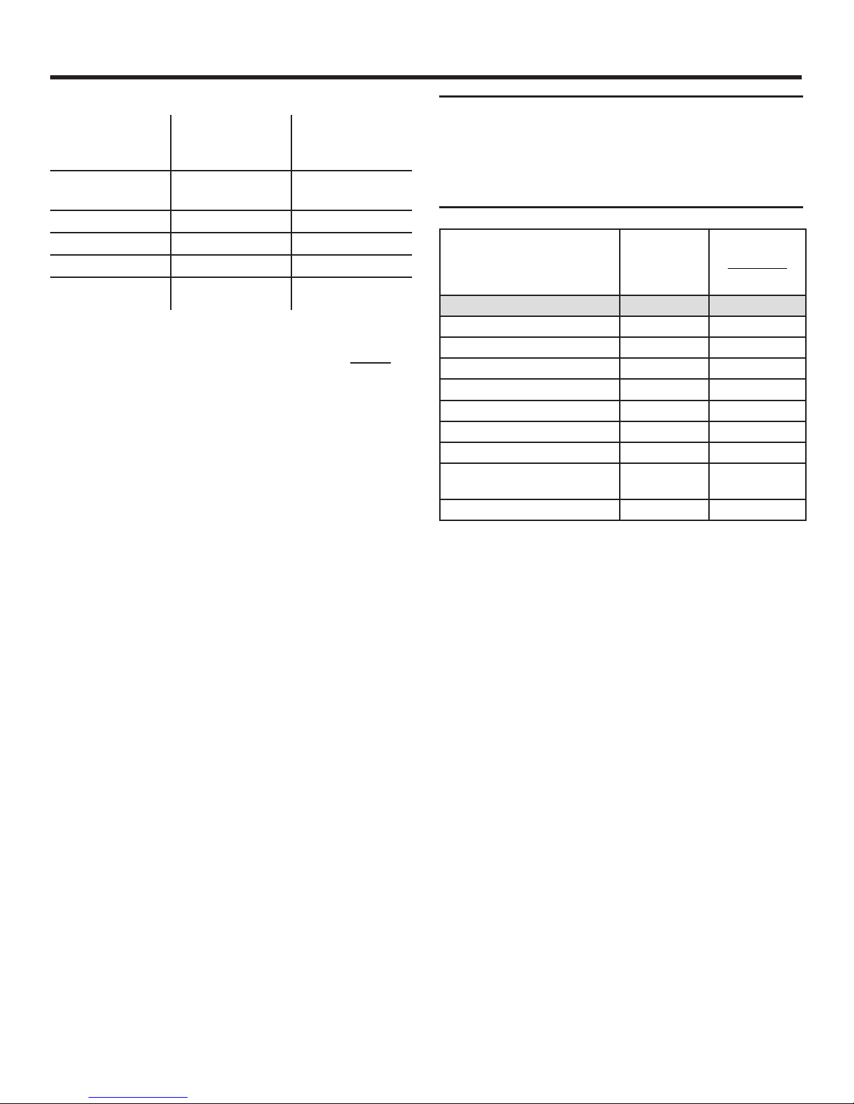
ELECTRIC MOTOR LOADS
It is characteristic of common electric motors in normal operation to draw up to six times their running current while starting. This table may be used to estimate the watts required to start “Code G” electric motors; however, if an electric motor
fails to start or reach running speed, turn off the appliance or tool immediately to avoid equipment damage. Always check
the requirements of the tool or appliance being used compared to the rated output of the generator.
Motor Size (H.P.) Running Watts
1/8 275 600 850 1200
1/6 275 600 850 2050
1/4 400 850 1050 2400
1/3 450 975 1350 2700
1/2 600 1300 1800 3600
3/4 850 1900 2600 —
1 1100 2500 3300 —
Repulsion Induction Capacitor Split Phase
CONTROL PANEL CORD
See Figure 1.
The 25-ft. control panel cord (Model RDEC25) has a 240 Volt,
20 Amp twist lock plug on one end and a 240 Volt, 20 Amp
twist lock receptacle on the other end. It also has a 12 Volt
DC engine control connector on each end. When using this
cord, the removable control panel can provide power through
the 2 x 120 Volt duplex GFCI outlets on the control box.
CAUTION:
Use only with RDEC25 control panel cord. Do not
exceed separation length of 75 ft. or a combination
of three RDEC25 control panel cords.
CAUTION:
Operating voltage and frequency requirement of
all electronic equipment should be checked prior
to plugging them into this generator. Damage may
result if the equipment is not designed to operate
within a +/- 10% voltage variation, and +/- 3 hz
frequency variation from the generator name
plate ratings. To avoid damage, always have an
additional load plugged into the generator if solid
state equipment (such as a television set) is used.
A power line conditioner is recommended for some
solid state applications.
Watts Required to Start Motor
GROUND FAULT CIRCUIT INTERRUPTER
See Figure 2.
The 20 amp, 120 volt receptacles on the generator are protected by a Ground Fault Circuit Interrupter (GFCI), which
guards against the hazards of ground fault currents. An
example of ground fault current is the current that would
flow through a person who is using an appliance with faulty
insulation and, at the same time, is in contact with an electrical ground such as a plumbing fixture, wet floor, or earth.
GFCI receptacles do not protect against short circuits,
overloads, or shocks.
The GFCI receptacles can be tested with the TEST and
RESET buttons.
To test:
Depress the TEST button. This should cause the Reset
button to pop out.
To restore power, depress the RESET button.
Perform this test monthly to ensure proper operation of the
GFCI. If the generator is stored outdoors, unprotected from
the weather, test the GFCI receptacle before each use.
GENERATOR CAPACITY
Make sure the generator can supply enough continuous (running) and surge (starting) watts for the items you will power
at the same time. Follow these simple steps.
1. Select the items you will power at the same time.
2. Total the continuous (running) watts of these items. This is
the amount of power the generator must produce to keep
the items running. See the wattage reference chart at right.
3. Estimate how many surge (starting) watts you will need.
Surge wattage is the short burst of power needed to
start electric motor-driven tools or appliances such as a
circular saw or refrigerator. Because not all motors start
at the same time, total surge watts can be estimated by
adding only the item(s) with the highest additional surge
watts to the total rated watts from step 2.
8 — English
ELECTRICAL
Example:
Estimated*
Tool or Appliance
Continuous
(Running) Watts
Quartz Halogen
Work Light
Reciprocating Saw
Electric Drill
Circular Saw
1000 0
960 +960
600 +900
1400 +2300
3960 Total
Running Watts
Total Continuous (Running) Watts 3960
Plus Highest Additional Surge Watts + 2300
Equals Total Generator Output Required 6260
POWER MANAGEMENT
To prolong the life of the generator and attached devices,
it is important to take care when adding electrical loads to
the generator. There should be nothing connected to the
generator outlets before starting its engine. The correct and
safe way to manage generator power is to sequentially add
loads as follows:
1. With nothing connected to the generator, start the engine
as described later in this manual.
2. Plug in and turn on the first load, preferably the largest
load you have.
3. Permit the generator output to stabilize (engine runs
smoothly and attached device operates properly).
4. Plug in and turn on the next load.
5. Again, permit the generator to stabilize.
6. Repeat steps 4 and 5 for each additional load.
Never add more loads than the generator capacity. Take
special care to consider surge loads in generator capacity
as previously described.
Estimated*
Additional Surge
(Starting) Watts
+2300 Highest
Surge Watts
CAUTION:
Do not overload the generator’s capacity. Exceeding
the generator’s wattage/amperage capacity can
damage the generator and/or electrical devices
connected to it.
Estimated*
Tool or Appliance
DIY/Job Site
Quartz Halogen Work Light 1000 0
Airless Sprayer − 1/3 HP 600 +1200
Reciprocating Saw 960 +960
Electric Drill − 1/2 HP 600 +900
Circular Saw − 7-1/4 in. 1400 +2300
Miter Saw − 10 in. 1800 +1800
Planer/Jointer − 6 in. 1800 +1800
Table Saw/Radial Arm Saw −
10 in.
Air Compressor − 1 HP 1600 +4500
*Wattages listed are approximate. Check tool or equipment for actual wattage.
Running
Watts
2000 +2000
Estimated*
Additional
Starting Watts
9 — English

FEATURES
PRODUCT SPECIFICATIONS
ENGINE
Engine Type .......................Yamaha MZ360, 4 Stroke, OHV
Bore x Stroke .............................................85 mm x 63 mm
Cooling System ...................................................Forced Air
Compression Ratio ...................................................... 8.1:1
Starting System ......................................................... Recoil
Ignition System ............................................................T.C.I.
Spark Plug .....................................................NGK BPR4ES
Engine Lubricant Volume...........................................1.1 qt.
Fuel Volume ................................................................ 8 gal.
GENERATOR
Rated Voltage .....................................................120V/240V
Rated Amps ..................................................... 56.7A/28.3A
Rated Output ..........................................................6,800 W
Maximum Output....................................................8,500 W
Rated Frequency ........................................................60 Hz
DIMENSIONS
Length ....................................................................... 31 in.
Width .......................................................................... 30 in.
Height ......................................................................... 27 in.
Weight .................................................................... 228 lbs.
KNOW YOUR GENERATOR
See Figure 3.
The safe use of this product requires an understanding of the
information on the product and in this operator’s manual as
well as a knowledge of the project you are attempting. Before
use of this product, familiarize yourself with all operating
features and safety rules.
AC CIRCUIT BREAKER
The circuit breaker is provided to protect the generator
against electrical overload. The circuit breaker may be reset
by pressing the circuit breaker reset button.
AIR FILTER
The air filter helps to limit the amount of dirt and dust drawn
into the unit during operation.
CHOKE LEVER
The choke lever is used when starting the engine.
CONTROL PANEL CORD
The 25-ft. control panel cord (Model # RDEC25) has a
120/240 Volt, 20 Amp twist lock plug and a 12 Volt DC engine
control connector on each end. When using this cord with
the removable control panel, appropriate equipment can be
powered through the 2 x 120 Volt duplex GFCI outlets on
the removable control panel.
FUEL TANK
The fuel tank has a capacity of 8 gallons.
FUEL VALVE
The flow of fuel through the generator is controlled by the
position of the fuel valve.
GenSmart™ MONITORING SYSTEM
The GenSmart monitoring system tracks usage and load
and alerts the operator when periodic engine maintenance
is needed.
NOTE: GenSmart™ load indicator monitors the load only
for the 120 Volt, 20 Amp GFCI outlets on the removable
control panel. It does not measure load on the 240 Volt, 30
Amp outlet.
GROUND TERMINAL
The ground terminal is used to assist in properly grounding the generator to help protect against electrical shock.
Consult with a local electrician for grounding requirements
in your area.
OFF SWITCH
The generator has two off switches: one on the removable
control panel and one on the stationary control panel. To
turn the engine off, press and hold the OFF switch until the
engine stops.
OIL CAP/DIPSTICK
Remove the oil fill cap to check and add lubricant to the
generator when necessary.
10 — English
FEATURES
OIL DRAINAGE BOLT
When changing the engine lubricant, the oil drainage bolt is
loosened to allow old engine lubricant to be drained.
RECEPTACLES
The following single phase, 60 Hz outlets on the control panel
can be used for operating appropriate equipment, electrical
lighting, tools, and motor loads: 2 x 120 Volt duplex GFCI 20
Amp receptacles, and one 240 Volt AC, 30 Amp receptacle.
A 240 Volt AC, 20 Amp receptacle plugged into the side of
the removable control panel is available when the panel is
detached.
ASSEMBLY
UNPACKING
This product requires assembly.
Carefully cut the box down the sides then remove the
machine and any accessories from the box. Make sure
that all items listed in the packing list are included.
NOTE: This machine is heavy and requires a minimum of
two people to lift. To avoid back injury, lift with your legs
and not your back.
WARNING:
Do not use this product if any parts on the Loose
Parts List are already assembled to your product
when you unpack it. Parts on this list are not
assembled to the product by the manufacturer and
require customer installation. Use of a product that
may have been improperly assembled could result
in serious personal injury.
Inspect the product carefully to make sure no damage
occurred during shipping.
Do not discard the packing material until you have carefully
inspected and satisfactorily operated the product.
If any parts are damaged or missing, please call
1-866-539-1710, for assistance.
RECOIL STARTER GRIP
The recoil starter is pulled to start the machine.
REMOVABLE CONTROL PANEL
The removable control panel can be wall-mounted for use
with the control panel cord for operation in a variety of
locations.
WARNING:
If any parts are damaged or missing do not operate
this product until the parts are replaced. Use of
this product with damaged or missing parts could
result in serious personal injury.
WARNING:
Do not attempt to modify this product or create
accessories not recommended for use with this
product. Any such alteration or modification is
misuse and could result in a hazardous condition
leading to possible serious personal injury.
WARNING:
Do not attempt to operate the generator until
assembly is complete. Failure to comply could
result in possible serious personal injury.
11 — English

ASSEMBLY
LOOSE PARTS LIST
See Figure 4.
The following items are included with the generator:
Key
No. Description Qty.
1 Axle ......................................................................2
2 Wheel ...................................................................2
3 Flat Washer (5/8 in.) .............................................2
4 Hitch Pin ..............................................................2
5 Screw (1/4-20 x 2 in., Hex Hd.) ...........................4
6 Flat Washer (1/4 in.) .............................................6
7 Left and Right Legs with Rubber Feet .................2
8 Nut (1/4-20 Self-Locking Nut) .............................6
9 Control Panel Cord, 25 ft .....................................1
10 Engine Lubricant..................................................1
11 Screw (1/4-20 x 1 in., Hex Hd.) ...........................2
Operator’s Manual (not shown) ...........................1
TOOLS NEEDED
See Figure 5.
The following tools (not included or drawn to scale) are
needed for assembly:
7/16 in. Socket Wrench
7/16 in. and 8 mm Combination Wrench
NOTE: Do not put fuel or lubricant in the generator before
installing the legs and wheels.
INSTALLING LEGS
See Figure 6.
Locate the following items:
Left and right legs with rubber feet
6 flat washers
6 lock nuts
4 screws (2 in.)
2 screws (1 in.)
Raise the front end of the generator, where the engine is
located, high enough to gain access to the frame bottom;
securely position props underneath to support.
Position a leg over the holes on each side of the frame
support. The tab on the leg should face the inside of the
generator frame.
Insert each 2 in. screw through a flat washer and insert
the screws through the two holes in the frame and the
leg.
Fasten the screws by installing a self-locking nut over
each screw on the inside of the frame. Tighten the nut
securely.
Insert a 1 in. screw through a flat washer, the hole in the
frame crossbar, and then through the hole in the leg tab.
Install a self-locking nut and tighten to secure.
Repeat with remaining leg.
INSTALLING THE WHEELS
See Figure 7.
Wheels are provided to assist in moving the generator to the
desired location and should be installed on the side opposite
the recoil starter.
Locate the following items:
2 axles
2 washers (5/8 in.)
2 hitch pins
2 wheels
Raise the handle end of the generator
gain access to the frame bottom; securely position props
underneath to support.
Insert an axle through the center of the wheel.
Place a washer on the axle, then slide the axle through
the bracket on the frame.
Slide the hitch pin through the hole in the axle and make
sure it is secure.
Repeat the process on the other side to install second
wheel.
high enough to
INSTALLING A WALL MOUNT FOR THE
REMOVABLE CONTROL PANEL
See Figures 8 - 10.
The removable control panel can be removed from the
generator and wall-mounted in another location before reconnecting it to the generator.
To detach the removable control panel from the
generator:
Turn off the generator.
Loosen the latch on the removable control panel and pull
the control panel forward.
Disconnect the twist-lock plug and the 12V engine control
connector on the back of the control panel.
To wall-mount the removable control box:
Screws or nails for hanging the box should be spaced
4-1/4 in. from center to center.
Mark the 4-1/4 in. measurement on a wall stud or other
sturdy wood surface.
Drill holes and insert the screws; tighten the screws
securely into the wood. If using nails, the nail head should
be large enough to hold the control panel securely.
NOTE: There should be at least 5/8 in. of the screw or nails
protruding from the wood piece for hanging the box.
Hang the box on the screws or nails, making certain it is
secure.
12 — English
OPERATION
DANGER:
Carbon Monoxide. U sin g a g ene ra tor
indoors WILL C AN YOU IN M INUTE S.
Generator exhaust contains high levels of carbon
monoxide (CO), a poisonous gas you cannot see
or smell. If you can smell the generator exhaust,
you are breathing CO. But even if you cannot smell
the exhaust, you could be breathing CO.
Never use a generator inside homes, garages, crawl-
spaces, or other partly enclosed areas. Deadly levels of
carbon monoxide can build up in these areas. Using a fan
or opening windows and doors does NOT supply enough
fresh air.
ONLY use a generator outdoors and far away from open
windows, doors, and vents. These openings can pull in
generator exhaust.
Even when you use a generator correctly, CO may leak into
the home. ALWAYS use a battery-powered or battery-backup
CO alarm in the home.
If you start to feel sick, dizzy, or weak after the generator has
been running, move to fresh air RIGHT AWAY. See a doctor.
You could have carbon monoxide poisoning.
DANGER:
Failure to properly ground generator can result
in electrocution, especially if the generator is
equipped with a wheel kit. National Electric Code
requires generator to be properly grounded to an
approved earth ground. Call an electrician for local
grounding requirements.
WARNING:
Do not allow familiarity with this product to make
you careless. Remember that a careless fraction of
a second is sufficient to inflict serious injury.
WARNING:
Do not use any attachments or accessories not
recommended by the manufacturer of this
product. The use of attachments or accessories
not recommended can result in serious personal
injury.
APPLICATIONS
This generator is designed to supply electrical power for
operating compatible electrical lighting, appliances, tools,
and motor loads.
BEFORE OPERATING THE UNIT
Only use OUTSIDE and far away from windows, doors,
and vents.
NEVER use inside a home or garage, EVEN IF doors and
windows are open.
Always position the generator on a flat, firm surface.
CAUTION:
Attempting to start the engine before it has been
properly filled with lubricant will result in equipment
failure.
RAISING AND LOWERING THE HANDLE
See Figure 11.
To raise the handle (for moving the generator): pull the
handle up until the handle release knob snaps into locking position and insert the handle lock pin to secure the
handle in place.
To lower the handle (for storing or transporting the gen-
erator): remove the handle lock pin, then pull the handle
release knob out and lower the handle to the down position.
Never use the handle to lift the generator. The handle should
only be used for moving the unit by rolling it on its wheels.
CHECKING/ADDING LUBRICANT
See Figure 12.
Engine lubricant has a major influence on engine performance and service life. For general, all-temperature use,
SAE 10W-30 is recommended. Always use a 4-stroke motor
lubricant that meets or exceeds the requirements for API
service classification SJ.
This engine comes with a feature that will shut off the engine
when a specific oil level is not maintained. The engine will
not restart until an appropriate oil level is reached.
NOTE: Non-detergent or 2-stroke engine lubricants will
damage the engine and should not be used.
Unscrew the oil cap/dipstick and remove.
Wipe dipstick clean and re-seat in hole; do not re-
thread.
Remove dipstick again and check lubricant level. Lubri-
cant level should fall between the hatched areas on the
dipstick.
13 — English

OPERATION
If level is low, add engine lubricant until the fluid level rises
to the upper portion of the dipstick.
Replace and secure the oil cap/dipstick.
CHECKING/ADDING FUEL
See Figure 13.
Remove the fuel cap.
Fill the fuel tank to 1 in. below the top of the fuel neck.
Replace and secure the fuel cap.
NOTE: Always use unleaded gasoline with a pump octane
rating of 86 or higher. Never use old, stale, or contaminated
gasoline, and do not use an oil/gas mixture. Do not allow dirt
or water into the fuel tank. Do not use E85 fuel.
USING FUEL STABILIZER
Fuel gets old, oxidizes, and breaks down over time. Adding
a fuel stabilizer (not included) extends the usable life of fuel
and helps prevent deposits from forming that can clog the
fuel system. Follow fuel stabilizer manufacturer’s directions
for correct ratio of stabilizer to fuel.
Add stabilizer to fuel tank, then fill with gasoline following
previous instructions.
NOTE: Fuel stabilizer and gasoline can be mixed prior
to filling the tank by using a gas can or other approved
fuel container and shaking gently to combine.
Replace and secure the fuel tank cap.
Start and run the engine for at least 5 minutes to allow
stabilizer to treat the entire fuel system.
OXYGENATED FUELS
DO NOT USE E85 FUEL. IT WILL VOID YOUR WARRANTY.
NOTE: Fuel system damage or performance problems
resulting from the use of an oxygenated fuel containing more
than the percentages of oxygenates stated below are not
covered under warranty.
Ethanol. Gasoline containing up to 10% ethanol by volume
(commonly referred to as E10) or 15% ethanol by volume
(commonly referred to as E15) are acceptable. E85 is not.
CAUTION:
On a level surface with the engine off, check the
lubricant level before each use of the generator.
REMOVABLE CONTROL PANEL
See Figure 14.
The removable control panel can be wall-mounted and connected to the generator with the 25-ft. control panel cord
(Model # RDEC25) provided with the product.
The generator can be turned OFF from the removable control
panel or the off switch on the unit.
NOTE: You must push the off switch and hold it until the
engine has fully stopped.
The removable control panel has two 120 Volt duplex GFCI
power outlets with outlet covers. Each duplex outlet has a
Test and a Reset push button.
NOTE: The GFCI outlets may be shown without their covers
for clearer instruction of this feature’s operation.
Use only with RDEC25 control panel cord. Do not exceed
separation length of 75 ft. or a combination of three RDEC25
control panel cords.
GENERATOR CONTROL PANEL
See Figure 14.
The stationary control panel has a twist-lock 240 Volt outlet
and circuit breakers.
GenSmart™ MONITORING SYSTEM
See Figure 15.
The GenSmart™ monitoring system has the following features:
Load Indicator
Measures the wattage output of the 2 x 120 Volt duplex GFCI
outlets located on the removable control panel. GenSmart™
monitors the load only for the 120 Volt GFCI outlets on the
removable control panel. It does not measure load on the
240 Volt, 30 Amp outlet. The GenSmart™ indicator measures
up to 4,800 watts of the generator’s rated wattage.
NOTE: If the 240 Volt receptacle is in use, the load indicated
on the display will not accurately reflect the exact percentage
of load being drawn from the generator.
Hour Meter
The digital hour meter operates whenever the engine is running and keeps track of how many hours the unit has been
used. Use this meter along with the accompanying engine
manual to determine when and what type of service on the
unit is needed.
14 — English

OPERATION
Maintenance Warning System
At every 100 hours of use, the GenSmart™ monitoring system
will display a message informing the operator to service the
engine’s air filter, spark plug, and engine oil. To reset this
message, push and hold the reset button located underneath
the GenSmart™ display for 5 seconds.
Reading the GenSmart™ Monitoring System
At startup, the unit will display a message instructing the
operator to read and understand the operator’s manual
before using this product.
While the generator is running, the panel will display a
power bar, load percentage, and total hours the unit has
been operated.
At every 100 hours of use, a message will scroll across the
display telling the operator to service the air filter, engine oil
and spark plugs, and to push and hold the reset button for
5 seconds to reset the display.
NOTE: Be careful to only press and hold the reset button
when you want the maintenance panel to be reset.
OPERATING THE GENERATOR USING THE
WALL-MOUNTED REMOVABLE CONTROL
PANEL
See Figure 16.
If the panel has been installed in a remote location:
Turn off the generator.
Connect the generator to the removable control panel
using the twist-lock plug and the 12 Volt DC engine control
connector on the provided control panel cord.
ONLY use a generator outdoors and far away from open
windows, doors, and vents. These openings can pull in
generator exhaust.
Connect up to two additional 25 ft. control panel cords
to the provided 25 ft. control panel cord. The total length
of all connected cords should not exceed 75 ft. or
three (3) RDEC25 control panel cords.
Connect the control panel cord to the generator.
Start the engine as described in Starting the Engine.
Add devices to the generator and monitor the load of
each added device using the GenSmart™ display panel.
MOVING THE GENERATOR
See Figures 17 - 18.
Turn the engine off ( O ). Disconnect any equipment that
is plugged into the generator.
Turn the fuel valve to the OFF position.
Allow 30 minutes of “cool down” time before storing the
machine.
For security, insert the handle lock pin to secure the
handle before moving.
NOTE: To help keep the handle lock pin securely in the
hole, push the joined area of the lanyard toward the inside
of the generator frame.
With your foot on the rear of the frame, tilt the machine
toward you until it balances on the wheels, then roll the
machine to the desired location.
LIFTING THE GENERATOR
See Figure 19.
Fold the handle to the down position. Never lift or carry
this product using the handle.
NOTE: This tool is heavy and requires several people to lift.
To avoid back injury, keep your knees bent and lift with your
legs, not your back, and get help when needed.
STARTING THE ENGINE
See Figure 20.
NOTE: If location of generator is not level, the unit may not
start or may shut down during operation.
Unplug all loads from the generator.
Turn the fuel valve to the ON position.
Move the choke lever right to the START position.
NOTE: If engine is warm or the temperature is above
50˚F, move the choke lever left to the RUN position.
Pull the recoil starting grip until the engine runs (a maxi-
mum of 6 times).
NOTE: Do not allow the grip to snap back after starting;
return it gently to its original place.
Allow the engine to run for 30 seconds, then move the
choke lever left to the RUN position.
STOPPING THE ENGINE
See Figure 21.
To stop the engine under normal operating conditions:
Remove any load from the generator.
To turn the engine off, press and hold the OFF switch until
the engine stops.
NOTE: The generator has two off switches: one on the
removable control panel, and one on the stationary control
panel.
Turn the fuel valve to the OFF position.
NOTE: If it is necessary to shut the engine off immediately,
either off switch may be used if the removable control panel is
connected to the unit. The off switch on the stationary control
panel can be used as the primary engine OFF switch.
15 — English

MAINTENANCE
WARNING:
When servicing, use only identical RIDGID
replacement parts. Use of any other parts may
create a hazard or cause product damage.
Only the parts shown on the parts list are intended to be
repaired or replaced by the customer. All other parts should
be replaced at an authorized service center.
GENERAL MAINTENANCE
Keep the generator in a clean and dry environment where it
is not exposed to dust, dirt, moisture, or corrosive vapors.
Do not allow the cooling air slots in the generator to become
clogged with foreign material such as leaves, etc.
Do not use a garden hose to clean the generator. Water
entering the fuel system or other internal parts of the unit can
cause problems that will decrease the life of the generator.
To clean the unit:
Use a soft bristle brush and/or vacuum cleaner to loosen
and remove dirt and debris.
Clean air vents with low pressure air that does not exceed
25 psi.
Wipe the exterior surfaces of the generator with a damp
cloth.
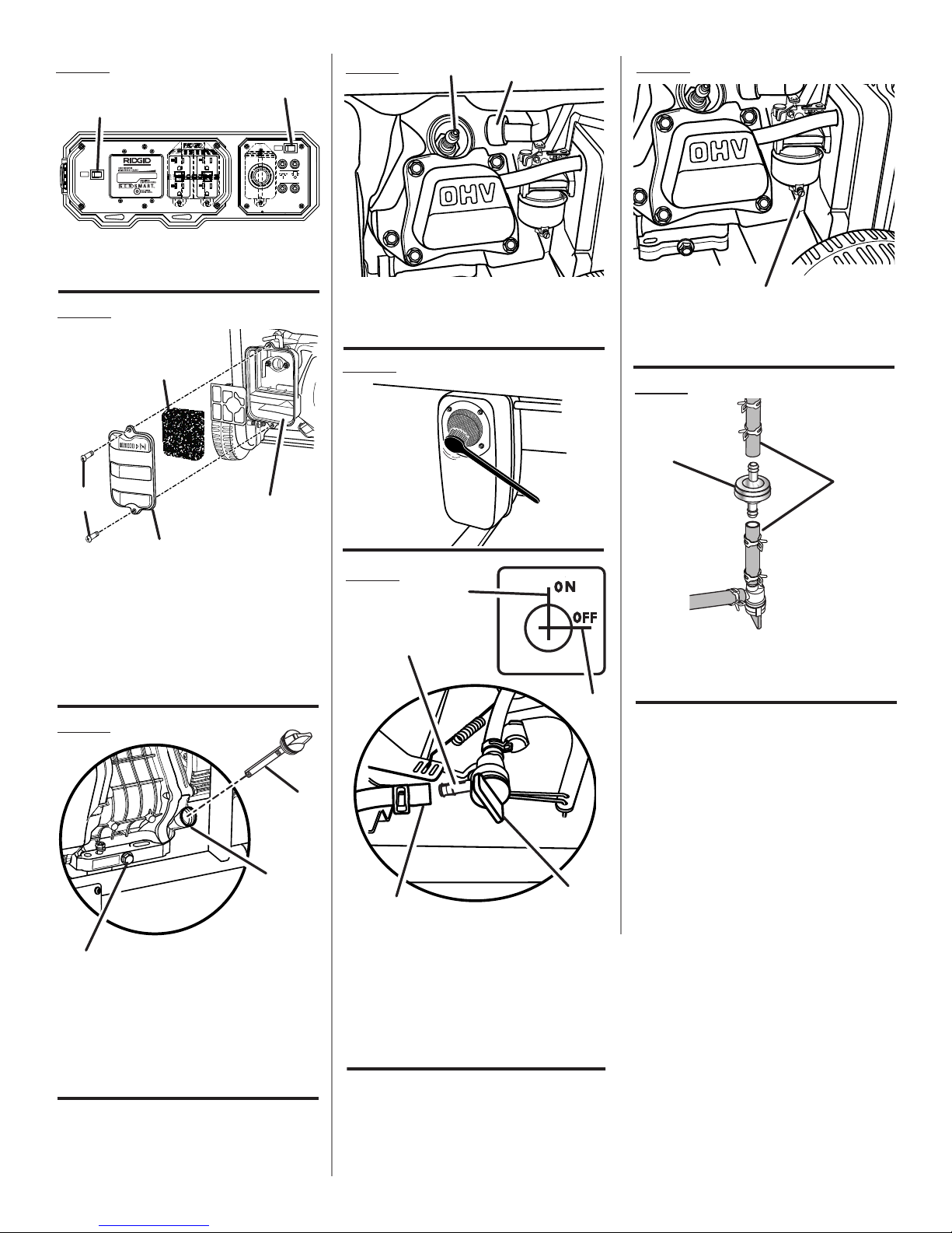
CHECKING/CLEANING AIR FILTER
See Figure 22.
For proper performance and long life, keep air filter clean.
Remove the screws from the air filter cover. Remove cover
and set aside.
Remove the filter element.
If the filter element is dirty, clean with warm, soapy water.
Rinse and let dry.
Apply a light coat of engine lubricant to the element, then
squeeze it out.
Replace the element in the air filter unit.
Replace the air filter cover and latch to secure.
NOTE: Do not run the generator without the air filter. Rapid
engine wear will result.
CHANGING ENGINE LUBRICANT
See Figure 23.
Remove the oil cap/dipstick.
Place a container underneath the oil drainage bolt to
collect used lubricant as it drains.
Unscrew the oil drainage bolt and remove.
Allow lubricant to drain completely.
Reinstall the oil drainage bolt and tighten securely.
Refill with lubricant following the instructions in the
Checking/Adding Lubricant section.
Reinstall the oil cap/dipstick.
NOTE: Used lubricant should be disposed of at an ap-
proved disposal site. See your local oil retailer for more
information.
SPARK PLUG MAINTENANCE
See Figure 24.
The spark plug must be properly gapped and free of deposits
in order to ensure proper engine operation. To check:
Remove the spark plug cap.
Clean any dirt from around base of spark plug.
Remove spark plug using wrench (not included).
Inspect spark plug for damage, and clean with a wire
brush before reinstalling. If insulator is cracked or
chipped, spark plug should be replaced.
NOTE: If replacing, use the following recommended spark
plugs or equivalent: NGK BPR4ES.
Measure plug gap. The correct gap is 0.028−0.031 in.
(0.7-0.8 mm). To widen gap, if necessary, carefully bend
the ground (top) electrode. To lessen gap, gently tap
ground electrode on a hard surface.
Seat spark plug in position; thread in by hand to prevent
cross-threading.
Tighten with wrench to compress washer. If spark plug
is new, use 1/2 turn to compress washer appropriate
amount. If reusing old spark plug, use 1/8 to 1/4 turn for
proper washer compression.
NOTE: An improperly tightened spark plug will become
very hot and could damage the engine.
CLEANING THE EXHAUST PORT AND MUFFLER
Depending on the type of fuel used, the type and amount of
lubricant used, and/or your operating conditions, the exhaust
port and muffler may become blocked with carbon deposits.
If you notice a power loss with your gas-powered products,
you may need to remove these deposits to restore performance. We highly recommend that only qualified service
technicians perform this service.
16 — English

MAINTENANCE
SPARK ARRESTOR
See Figure 25.
Inspect the spark arrestor for breaks or holes. Replace
if necessary. To purchase a replacement spark arrestor
contact RIDGID customer service at 1-866-539-1710.
Use a brush to remove carbon deposits from the spark
arrestor screen as needed.
DRAINING FUEL TANK/CARBURETOR
See Figures 26 - 27.
To help prevent gum deposits in the fuel system, drain the
fuel from the tank and carburetor before storing.
DRAINING THE FUEL TANK
Turn the engine OFF ( O ).
Turn the fuel valve to the OFF position.
Remove the fuel line from the petcock by squeezing the
ends of the retaining clip and sliding the fuel line off.
Install one end of a drain line over the petcock, and place
the other end in a fuel container large enough to catch
the fuel being drained from the tank.
Turn the fuel valve to the ON position.
For better fuel drainage, please tilt the unit toward the
fuel petcock slightly (approximately 1 in.).
When the fuel has drained from the tank, close the fuel
valve and reinstall fuel line securely on petcock.
DRAINING THE CARBURETOR
Turn the engine OFF ( O ).
Turn the fuel valve to the OFF position.
Position a suitable container under the carburetor drain
screw to catch fuel; loosen the screw.
Allow fuel to drain completely into container.
Retighten drain screw.
NOTE: Consult hazardous waste management guidelines in
your area for the proper way to dispose of used fuel.
REPLACING FUEL FILTER
See Figure 28.
Occasionally the fuel filter may become clogged and need
replacing. To purchase a replacement fuel filter contact
Ridgid customer service at 1-866-539-1710.
NOTE: Fuel tank must be empty before replacing fuel filter.
Run unit until tank is empty, if needed, or inspect filter prior
to fill-up.
To replace:
Turn the fuel valve to the OFF position.
Remove the fuel line from both sides of the filter by
squeezing the ends of the retaining clip with pliers.
Slide the fuel line off.
Replace with new fuel filter.
Reinstall fuel lines to new fuel filter.
Turn the fuel valve to the ON position.
TRANSPORTING
Turn the engine OFF ( O ).
Turn the fuel valve to the OFF position.
Make sure engine and exhaust of unit is cool.
Lower the handle.
Keep unit level while transporting to prevent fuel spill-
age.
Do not drop or strike unit or place under heavy objects.
17 — English
 Loading...