

RIDGID RD907000P Operator's Manual
BC
OPERATOR’S MANUAL
Manuel de l’opérateur
Manual del operador
PORTABLE GENERATOR
Génératrice portable
Generador portàtil
RD907000P
NOTICE AVIS AVISO
Do not use E15 or E85 fuel in this
product. It is a violation of federal law and will damage the unit
and void your warranty. Only use
unleaded gasoline containing up to 10% ethanol.
Ne pas utiliser d’essence E15 ou E85 dans ce produit.
Une telle utilisation représente une violation de la loi
fédérale et endommagera l’appareil et annulera la
garantie. Utiliser seulement de l’essence sans plomb
ne contenant pas plus de 10 % d’éthanol.
No utilice combustibles E15 o E85 con este producto.
Esto constituye una violación a la ley federal, dañará la
unidad y anulará la garantía. Utilice únicamente gasolina
sin plomo que contiene hasta 10% de etanol.
TABLE OF CONTENTS
Important Safety Instructions .......... 3-4
Specific Safety Rules ..........................4
Symbols .......................................... 5-7
Electrical ......................................... 8-9
Features ............................................10
Assembly .................................... 11-12
Operation .................................... 13-16
Maintenance ............................... 16-19
Troubleshooting ................................20
Warranty ............................................21
Parts Ordering / Service ...... Back Page
WARNING: To reduce the
risk of injury, the user must read and
understand the operator’s manual
before using this product.
CONNECTEUR NEUTRE RELIÉ AU CADRE,
PUNTO NEUTRO CONECTADO AL MARCO
TABLE DES MATIÈRES
Instructions importantes
concernant la sécurité ....................3-4
Règles de sécurité particulières ......... 4
Symboles ........................................5-7
Caractéristiques électriques ...........8-9
Caractéristiques ............................... 10
Assemblage ................................11-12
Utilisation ....................................13-16
Entretien ...................................... 16-19
Dépannage ....................................... 20
Garantie ........................................... 21
Commande de pièces /
réparation .......................... Páge arrière
AVERTISSEMENT : Pour
réduire les risques de blessures,
l’utilisateur doit lire et veiller à bien
comprendre le manuel d’utilisation
avant d’employer ce produit.
NEUTRAL BONDED TO FRAME
ÍNDICE DE CONTENIDO
Instrucciones de seguridad
importantes ..................................... 3-4
Reglas de seguridad específicas ....... 4
Símbolos ......................................... 5-7
Aspectos eléctricos ........................8-9
Características ................................. 10
Armado .......................................11-12
Funcionamiento ..........................13-16
Mantenimiento ............................16-19
Corrección de problemas ................ 20
Garantía ........................................... 21
Pedidos de piezas /
servicio ...........................Pág. posterior
ADVERTENCIA: Para reducir
el riesgo de lesiones, el usuario debe
leer y comprender el manual del
operador antes de usar este producto.
SAVE THIS MANUAL FOR
FUTURE REFERENCE
CONSERVER CE MANUEL
POUR FUTURE RÉFÉRENCE
GUARDE ESTE MANUAL
PARA FUTURAS CONSULTAS

See this fold-out section for all of the figures
referenced in the operator’s manual.
Consulter l’encart à volets afin d’examiner toutes les
figures mentionnées dans le manuel d’utilisation.
Consulte esta sección desplegable
para ver todas las figuras a las que se
hace referencia en el manual del operador.
ii
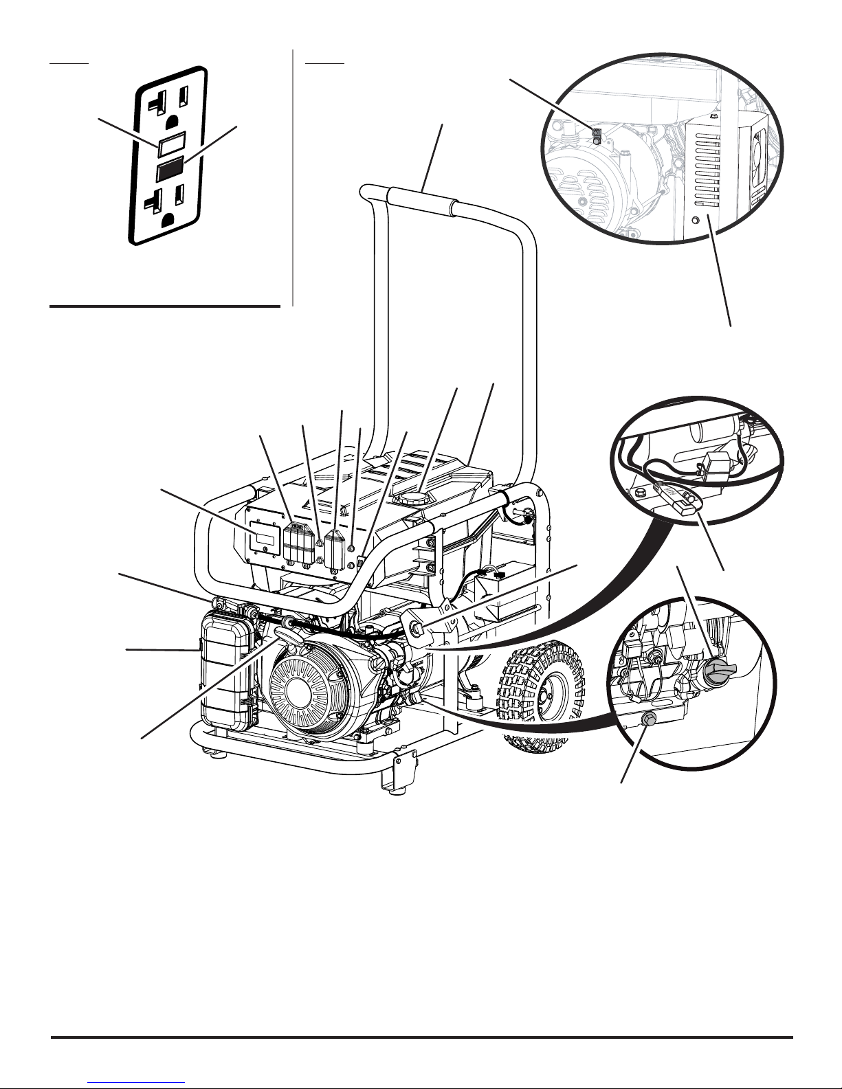
Fig. 1 Fig. 2
D
A
A - Reset button (bouton de réinitialisation,
botón de reajuste)
B - Test button (bouton de test, botón de prueba)
B
J
E
H
P
G
F
I
K
K
O
C
B
A
A - Recoil starter grip (poignée du démarreur à
rappel, mango del arrancador retráctil)
B - Air filter (filtre à air, filtro de aire)
C - Choke (volet de départ, anegador)
D - Ground terminal (borne de terre, terminal de
conexión a tierra)
E - GenSmart™ monitoring system (système
de surveillance GenSmart™, sistema de
monitoreo GenSmart™)
F - Fuel cap (bouchon de carburant, tapa del
tanque)
G - Fuel tank (réservoir de carburant, tanque de
combustible)
H - Handle (poignée, mango)
I - 240 V AC 30 amp receptacle (prise 240 V
C.A. 30 A, 240 V de CA 30 A receptáculo)
J - 120 volt AC GFCI 20 amp receptacles (prises
120 V C.A. GFCI 20 A, 120 V de CA GFCI 20 A
receptáculos)
K - AC circuit breaker [disjoncteur de C.A.,
disyuntor de circuito de CA]
L - Oil cap/dipstick (bouchon/jauge d’huile,
tapa de relleno de aceite/varilla medidora de
aceite)
N
L
Q
M
M - Oil drain plug (huiler le bouchon d’égout,
tapón de drenaje del aceite)
N - Fuel valve (robinet de carburant, válvula de
combustible)
O - Engine switch (commutateur de moteur,
interruptor del motor)
P - Muffler (silencieux, silenciador)
Q - Battery maintainer charging cable (câble de
charge de mainteneur de batterie, cable de
carga del mantenedor de carga de la batería)
iii
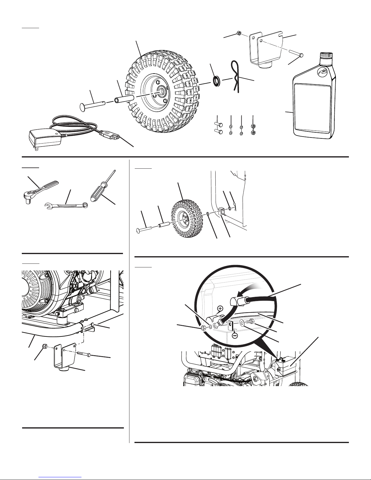
Fig. 3
3
6
7
2
1
Fig. 4
A
B
C
A - Socket wrench (clé à douille, llave de
casquillo)
B - Combination wrench (clé mixte, llave de
combinación)
C - Phillips screwdriver (Tournevis à pointe
cruciforme, Destornillador de cabeza Phillips)
14
Fig. 6
A
4
8
5
1210 119
C
D
F
B
E
D
A - Axle (essieu, eje)
B - Spacer (écarteur, espaciador)
C - Wheel (roue, rueda)
D - Washer (rondelle, arandela)
E - Mounting bracket (support de montage,
F - Hitch pin (goupille de sûreté, pasador de
13
soporte de montaje)
enganche)
Fig. 5
B
E
A
C
D
A - Bolt (boulon, perno)
B - Stud (goujon, vástago)
C - Lock nut (écrou de blocage, tuerca de
seguridad)
D - Leg with rubber foot (pied avec patin en
caoutchouc, pata con pie de goma)
E - Frame (cadre, armazón)
Fig. 7
I
G
A - Battery bracket (support de pile, soporte de la
batería)
B - Positive (+) terminal [borne positive (+), tapa
del terminal positiva (+)]
C - Negative (–) terminal [borne négative (–),
terminal negativa (–)]
B
D
H
E
C
D - Black wire (–) [fil noir (–), cable negro (–)]
E - Screw (vis, tornillo)
F - Washer (rondelle, arandela)
G - Nut (écrou tuerca)
H - Red wire (+) [fil rouge (+), cable rojo (+)]
I - Lock washer (rondelle frein, arandela de
seguridad)
F
A
iv
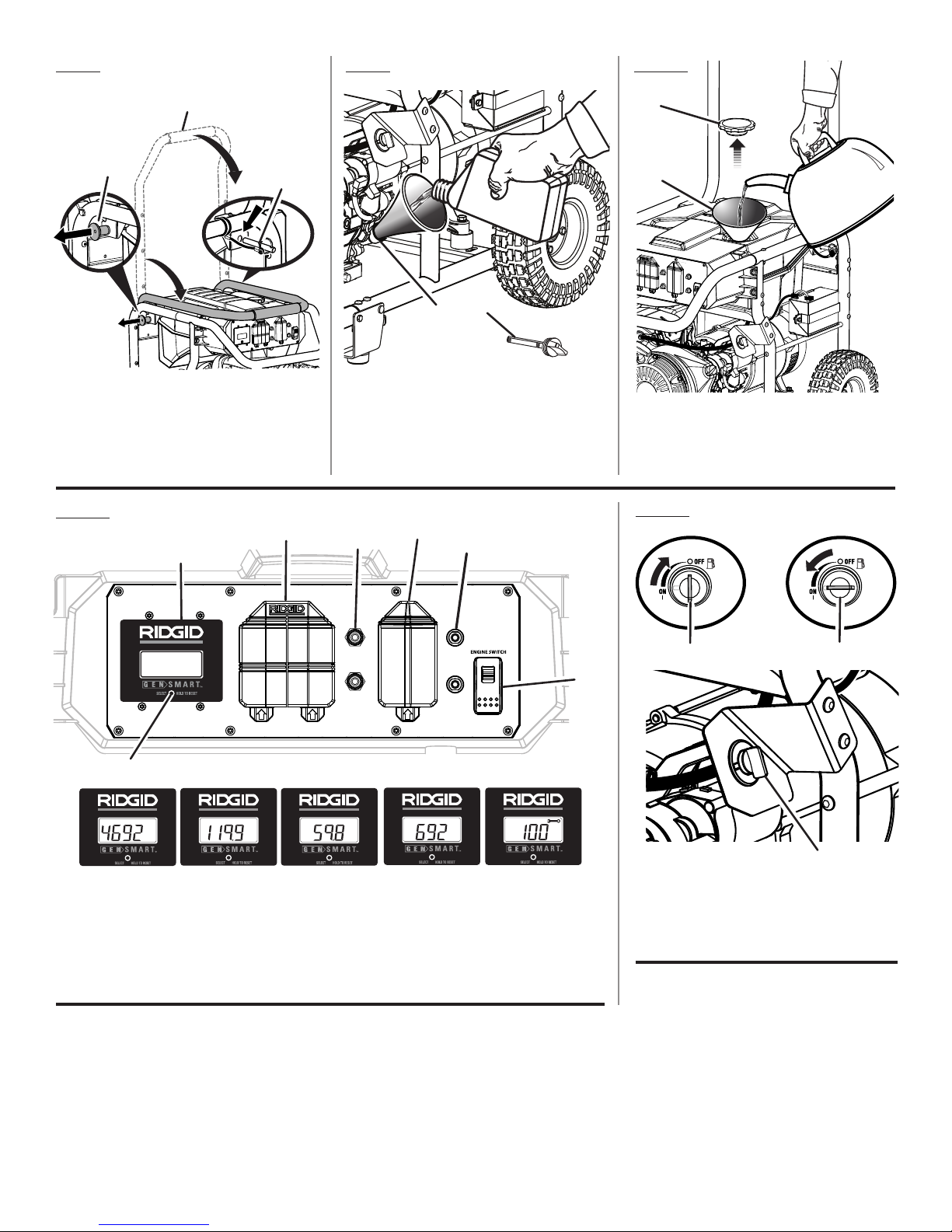
Fig. 8
Fig. 9
Fig. 10
A
B
A - Handle (poignée, mango)
B - Handle release knob (relâchez le bouton de
poignée, perilla de afloje del mango)
C - Handle lock pin (goupille de blocage de la
poignée, pasador de seguro del mango)
C
Fig. 11
D
B
A
B
A - Oil cap/dipstick (bouchon/ jauge d’huile,
tapa de relleno de aceite/varilla medidora de
aceite)
B - Oil fill hole (orifice de remplissage d’huile,
agujero de llenado de aceite)
E
C
E
A
B
A - Fuel cap (bouchon de carburant, tapa del
tanque de combustible)
B - Fuel tank (réservoir de carburant, tanque de
combustible)
Fig. 12
MAINTENANCE
Hz
HRS
F
MAINTENANCE
Hz
W
HRS
MAINTENANCE
Hz
W
HRS
A - Engine switch (commutateur du moteur,
interruptor del motor)
B - GenSmart™ monitoring system (système
de surveillance GenSmart™, sistema de
monitoreo GenSmart™)
C - 240 volt AC 30 amp receptacle (prise 240 V
C.A. 30 A, 240 V de CA 30 A receptáculo)
MAINTENANCE
A
MAINTENANCE
Hz
W
HRS
Hz
W
HRS
D - 120 volt AC 20 amp receptacles (prises 120
V C.A. 20 A, 120 V de CA 20 A receptáculos)
E - AC circuit breaker (disjoncteur de C.A.,
disyuntor de circuito de CA)
F - Reset/Select button (bouton « Reset / Select »
[réinitialisation / sélectionner], botón reajuste/
select)
MAINTENANCE
Hz
W
HRS
B
C
A
A - Fuel valve (robinet de carburant, válvula de
combustible)
B - Off (arret, apagado)
C - On (marche, encendido)
v

C
B
Fig. 19Fig. 13 Fig. 16
B
A
A - Choke (volet de départ, anegador)
B - START position (position de démarrage,
posición de arranque)
C - RUN position (position de marche, posición
de funcionamiento)
Fig. 14
A
C
2
1
B
D
A - Engine switch in ON position (le
commutateur de moteur dans de la position
MARCHE, coloque el interruptor del motor
en la posición ENCENDIDO)
B - Lock button (bouton de verrouillage , botón
del seguro)
C - Engine switch in START position (le
commutateur de moteur dans de la position
OUVERT, coloque el interruptor del motor
en la posición de ARRANQUE)
D - Engine switch in OFF position (le
commutateur de moteur dans de la position
ARRET, coloque el interruptor del motor en
la posición del APAGADO)
Fig. 17
Fig. 18
A
A - Container (jarre, recipiente)
B - Oil drain plug (huiler le bouchon d’égout,
tapón de drenaje del aceite)
Fig. 20
C
A - Spark plug cap (capuchon de bougie, tapa de
la bujía)
B - Spark plug (bougie, bujía)
A
B
Fig. 15
A
A - Recoil starter grip (manchon en lanceur à
rappel, agarradera del arranque retráctil)
B
A
A - Air filter cover (couvercle du filtre à air, tapa del
filtro de aire)
B - Filter element (élément du filtre, elemento
de filtro)
C - Latches (loquets, broches)
D - Air filter unit (unité de filtre à air, unidad del
filtro de aire)
D
C
vi
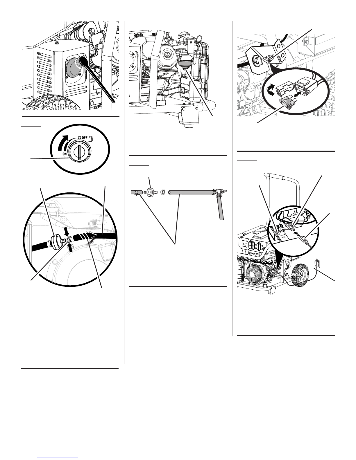
Fig. 21
Fig. 23
Fig. 25
A
Fig. 22
A
D
A
B
A - Carburetor drain screw (vis de vidange
du carburateur, tornillo de drenaje del
carburador
A - Fuse holder (support à fusible, soporte del
fusibles)
B - Fuse (fusible, fusible)
Fig. 26
Fig. 24
B
C
B
OFF
C
A
A - Fuel line (conduites de carburant, conducto
de combustible)
B - Fuel filter (filtre à carburant, filtro de
combustible)
B
A
E
A - Fuel valve (robinet de carburant, válvula de
combustible)
B - Fuel line (conduite de carburant, conducto de
combustible)
C - Fuel filter (filtre à carburant, filtro de
combustible)
D - Retaining clip (clip de retenue, pince de
retenue)
E - Fuel line holder (support de conduites
de carburant, soporte de conducto de
combustible)
A - Battery maintainer (cargador mantenedor
para baterías)
B - Battery charging cable (cable para cargar la
batería)
C - Cover (tapa)
vii
To register your RIDGID product,
please visit: http://register.RIDGID.com
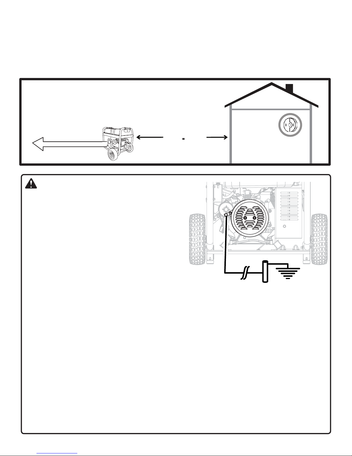
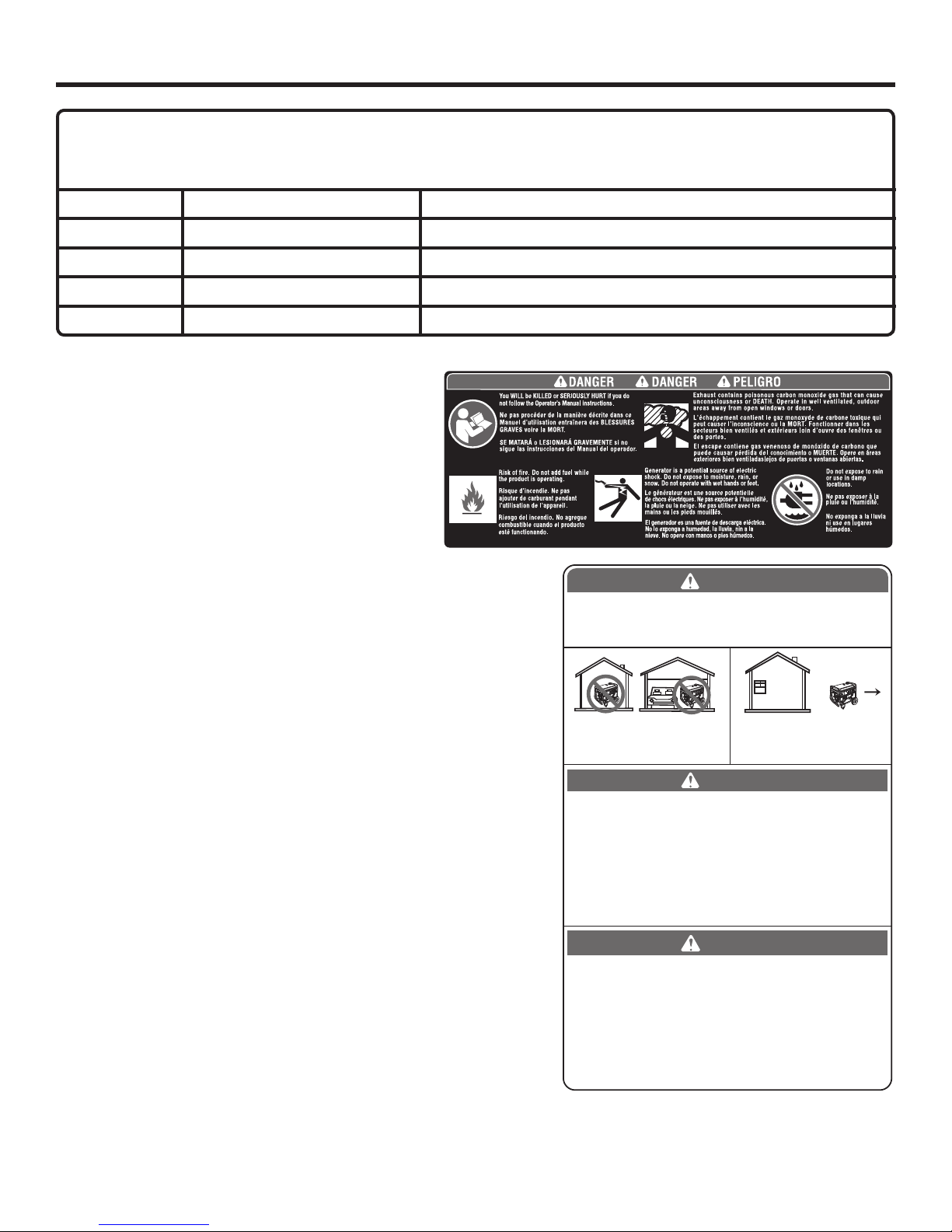
LOCATE GENERATOR AT LEAST 20 FT.* AWAY TO REDUCE THE
RISK OF CARBON MONOXIDE GETTING INSIDE THE HOME
* Minimum distance as recommended by U.S. Department of Health and Human
Services Centers for Disease Control and Prevention (www.cdc.gov/co). Your specific
home and/or wind conditions may require additional distance.
CO Detector
in Living Areas
Exhaust (CO)
Direct exhaust AWAY
from all windows, doors,
and vents.
KEEP AT LEAST
20 FT. AWAY
Only use OUTSIDE and
FAR AWAY from windows,
doors, and vents.
WARNING:
GROUNDING THE GENERATOR
If this generator will be used only with cord and plug-connected
equipment, National Electric Code does not require that the unit
be grounded. However, other methods of using the generator
may require grounding to reduce the risk of shock or electrocution. Consult a qualified electrician, electrical inspector, or
local agency having jurisdiction for local codes or ordinances
to find out if grounding is needed in your situation before using
the generator.
When grounding is required, the nut and ground terminal on
the frame are used to connect the generator to a suitable
ground source. The ground path should be made with #8 size
wire. Connect the terminal of the ground wire between the lock
washer and the nut, and tighten the nut fully. Connect the other
end of the wire securely to a suitable ground source that is in contact with the soil for a minimum distance of 8 ft.
The National Electric Code contains several practical ways in which to establish a good ground source. If a steel
or iron rod is used, it should be at least 5/8 in. diameter, and if a nonferrous rod is used, it should be at least 1/2 in.
diameter and be listed as material for grounding. If a rock bottom is encountered before reaching a depth of 8 ft., drive
the ground rod in at an angle of up to 45°. If the rock bottom is again encountered, the rod can be buried in a trench
that is at least 30 in. deep. In all cases, the upper end of the grounding rod should either be flush with (or below) the
ground or must be otherwise protected from physical damage.
All electrical tools and appliances operated from this generator must be properly grounded by use of a third wire or
be “Double Insulated.”
It is recommended to:
1. Use electrical devices with 3-prong grounded plugs.
2. Use an extension cord intended for outdoor use with a 3-pole receptacle and a 3-prong plug at opposite ends to
ensure continuity of the ground protection from the generator to the appliance.
Check and adhere to all applicable federal, state, and local regulations relating to grounding specifications. Consult a
qualified electrician or service personnel if the grounding instructions are not completely understood or if in doubt as
to whether the generator is properly grounded.
2 — English
IMPORTANT SAFETY INSTRUCTIONS
Do not start or operate the engine in a confined space,
DANGER:
Carbon Monoxide. Using a generator indoors CAN
KILL YOU IN MINUTES.
Generator exhaust contains high levels of carbon
monoxide (CO), a poisonous gas you cannot see or
smell. If you can smell the generator exhaust, you
are breathing CO. But even if you cannot smell the
exhaust, you could be breathing CO.
Never use a generator inside homes, garages,
crawlspaces, or other partly enclosed areas.
Deadly levels of carbon monoxide can build up
in these areas. Using a fan or opening windows
and doors does NOT supply enough fresh air.
ONLY use a generator outdoors and far away
from open windows, doors, and vents. These
openings can pull in generator exhaust.
Even when you use a generator correctly, CO may
leak into the home. ALWAYS use a battery-powered
or battery-backup CO alarm in the home.
If you start to feel sick, dizzy, or weak after the generator has been running, move to fresh air RIGHT
AWAY. See a doctor. You could have carbon monoxide poisoning.
WARNING:
Read and understand all instructions. Failure to
follow all instructions listed below could result in
electrocution, fire, and/or carbon monoxide poisoning, which can cause death or serious injury.
WARNING:
In some applications, National Electric Code
requires generator to be grounded to an approved
earth ground. Before using the ground terminal,
consult a qualified electrician, electrical inspector,
or local agency having jurisdiction for local codes
or ordinances that apply to the intended use of
the generator.
SAVE THESE INSTRUCTIONS
This manual contains important instructions for this product
that should be followed during installation and maintenance
of the generator.
Do not connect to a building’s electrical system unless
the generator and transfer switch have been properly
installed and the electrical output has been verified by
a qualified electrician. The connection must isolate the
generator power from utility power and must comply with
all applicable laws and electrical codes.
Do not allow children or untrained individuals to use this
unit.
building, near open windows, or in other unventilated
space where dangerous carbon monoxide fumes can
collect. Carbon monoxide, a colorless, odorless, and
extremely dangerous gas, can cause unconsciousness
or death.
Keep all bystanders, children, and pets at least 10 feet
away.
Wear sturdy and dry shoes or boots. Do not operate while
barefoot.
Do not operate generator when you are tired or under the
influence of drugs, alcohol, or medication.
Keep all parts of your body away from any moving parts
and all hot surfaces of the unit.
Do not touch bare wire or receptacles.
Do not use generator with electrical cords which are worn,
frayed, bare, or otherwise damaged.
Before storing, allow the engine to cool for 30 minutes
and drain fuel from the unit.
Do not operate or store the generator in rain, snow, or
wet weather.
Store the generator in a well-ventilated area with the fuel
tank empty. Fuel should not be stored near the generator.
Empty fuel tank, close fuel valve, and restrain the unit
from moving before transporting in a vehicle.
Provide a plastic sheet or absorbent pad below the
generator to catch any drips of fuel or lubricant when
transporting.
To reduce the risk of fire and burn injury, handle fuel with
care. It is highly flammable.
Do not smoke while handling fuel.
Store fuel in a container approved for gasoline.
Position the unit on level ground, stop engine, and allow
to cool for five minutes before refueling.
Loosen fuel cap slowly to release pressure and to keep
fuel from escaping around the cap.
Tighten the fuel cap securely after refueling.
Wipe spilled fuel from the unit.
Never attempt to burn off spilled fuel under any circum-
stances.
Generators vibrate in normal use. During and after the
use of the generator, inspect the generator as well as
extension cords and power supply cords connected to
it for damage resulting from vibration. Have damaged
items repaired or replaced as necessary. Do not use plugs
or cords that show signs of damage such as broken or
cracked insulation or damaged blades.
For power outages, permanently installed stationary
generators are better suited for providing back-up
power to the home. Even a properly connected portable
generator can become overloaded. This may result in
overheating or stressing the generator components,
possibly leading to generator failure.
3 — English
IMPORTANT SAFETY INSTRUCTIONS
Use only recommended or equivalent replacement parts
and accessories and follow instructions in the Mainte-
nance section of this manual. Use of any other parts or
failure to follow maintenance instructions may create a
risk of shock or injury.
SPECIFIC SAFETY RULES
DANGER:
Risk of fire and serious burns: Never remove
fuel cap when unit is running. Shut off engine and
allow the unit to cool at least five minutes. Remove
cap slowly.
WARNING:
When this generator is used to supply a building
wiring system: generator must be installed by a
qualified electrician and connected to a transfer
switch as a separately derived system in accordance with NFPA 70, National Electrical Code. The
generator shall be connected through a transfer
switch that switches all conductors other than
the equipment grounding conductor. The frame of
the generator shall be connected to an approved
grounding electrode. Failure to isolate the generator from power utility can result in death or injury
to electric utility workers.
Do not use this generator to provide power for emergency
medical equipment or life support devices.
This generator has a neutral bonded condition. This
means the neutral conductor is electrically connected to
the frame of the machine.
Always use a battery-powered carbon monoxide detector
when running the generator. If you begin to feel sick, dizzy,
or weak while using the generator, shut it off and get to
fresh air immediately. See a doctor. You may have carbon
monoxide poisoning.
Place the generator on a flat, stable surface with a slope
of no more than 4°.
Operate outdoors in a well-ventilated, well-lit area isolated
from working areas to avoid noise interference.
Operating the generator in wet conditions could result in
electrocution. Keep the unit dry.
Keep the generator a minimum of 3 feet away from all
types of combustible material.
Do not operate generator near hazardous material.
Maintain the unit per maintenance instructions in this
Operator’s Manual.
Inspect the unit before each use for loose fasteners, fuel
leaks, etc. Replace damaged parts.
Do not operate generator at a gas or natural gas filling
station.
Do not touch the muffler or cylinder during or immediately
after use; they are HOT and will cause burn injury.
Do not allow the generator’s gas tank to overflow when
filling. Fill to 1 in. below the top neck of the gasoline tank
to allow for fuel expansion. Do not cover the fuel tank cap
when the engine is running. Covering the fuel tank cap
during use may cause engine failure and/or damage to
the tool.
Do not smoke when filling the generator with gasoline.
Shut down the engine and allow to cool for five minutes
before adding gasoline or lubricant to the generator.
Do not remove the oil dipstick or the fuel tank cap when
the engine is running.
Pay close attention to all safety labels located on the
generator.
Keep children a minimum of 10 feet away from the
generator at all times.
The unit operates best in temperatures between 23°F and
104°F with a relative humidity of 90% or less.
Operating voltage and frequency requirement of all
electronic equipment should be checked prior to plugging
them into this generator. Damage may result if the
equipment is not designed to operate within a +/- 10%
voltage variation, and +/- 3 hz frequency variation from
the generator name plate ratings. To reduce the risk of
damage, always have an additional load plugged into the
generator if solid state equipment (such as a television
set) is used. A power line conditioner is recommended
for some solid state applications.
When battery is not in use, keep it away from other metal
objects like paper clips, coins, keys, nails, screws, or other
small metal objects that can make a connection from
one terminal to another. Shorting the battery terminals
together may cause burns or a fire.
For outdoor use only.
Save these instructions. Refer to them frequently and use
them to instruct others who may use this product. If you
loan someone this product, loan them these instructions
also.
4 — English
SYMBOLS
The following signal words and meanings are intended to explain the levels of risk associated with this product.
SYMBOL SIGNAL MEANING
DANGER:
WARNING:
CAUTION:
NOTICE:
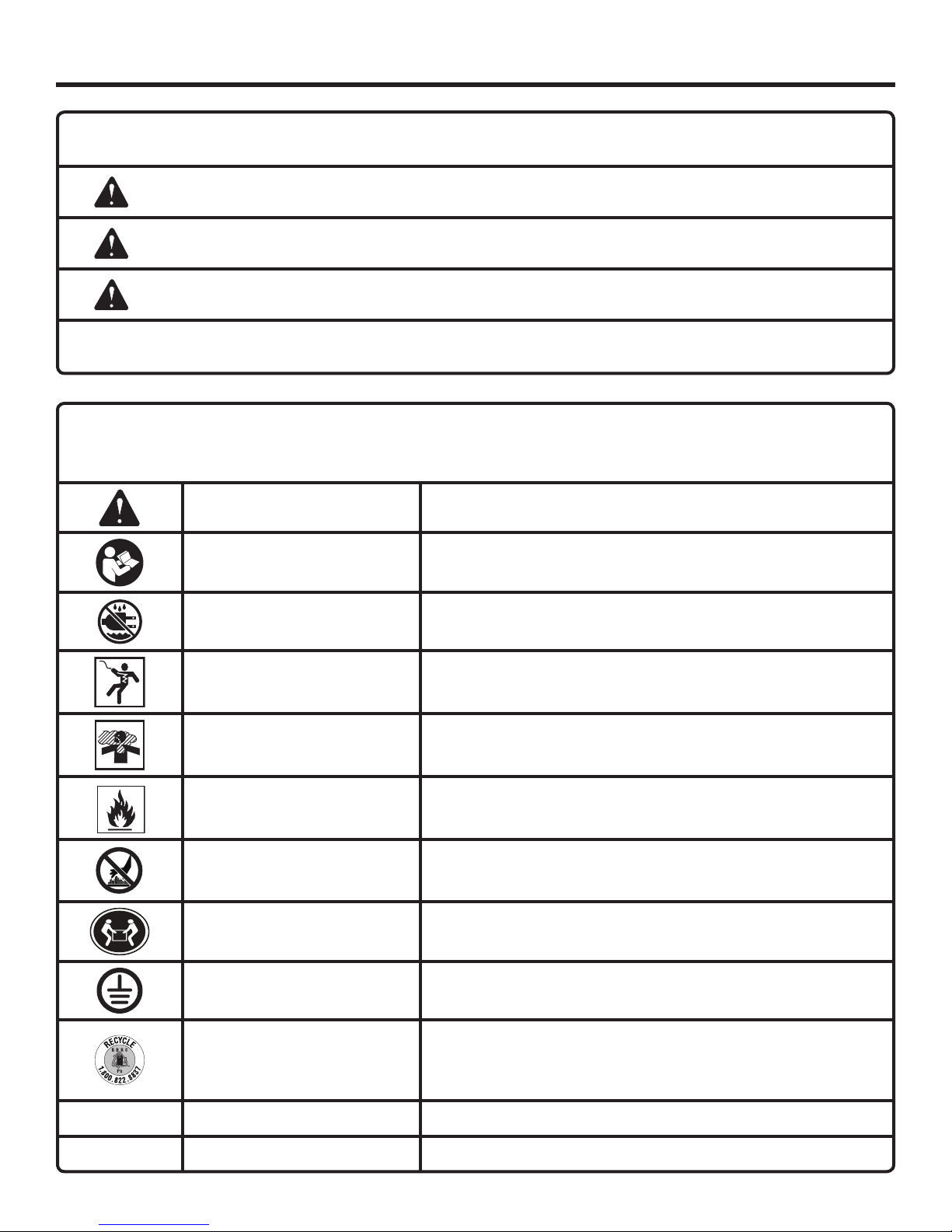
Some of the following symbols may be used on this product. Please study them and learn their meaning. Proper
interpretation of these symbols will allow you to operate the product better and safer.
Indicates an imminently hazardous situation, which, if not avoided, will result
in death or serious injury.
Indicates a potentially hazardous situation, which, if not avoided, could result
in death or serious injury.
Indicates a potentially hazardous situation, which, if not avoided, may result in
minor or moderate injury.
(Without Safety Alert Symbol) Indicates important information not related to an
injury hazard, such as a situation that may result in property damage.
SYMBOL NAME DESIGNATION/EXPLANATION
Safety Alert Indicates a potential personal injury hazard.
Read Operator’s Manual
Wet Conditions Alert Do not expose to rain or use in damp locations.
To reduce the risk of injury, user must read and understand
operator’s manual before using this product.
Electric Shock
Toxic Fumes
Fire/Explosion
Hot Surface and Exhaust
Gases
Lifting Hazard
Ground
Recycle Symbol
V Volts Voltage
Failure to use in dry conditions and to observe safe practices can
result in electric shock.
Running generator gives off carbon monoxide, an odorless,
colorless, poison gas. Breathing carbon monoxide can cause
nausea, fainting, or death.
Fuel and its vapors are extremely flammable and explosive. Fire
or explosion can cause severe burns or death.
To reduce the risk of injury or damage, avoid contact with any
hot surface and do not place any body parts in the path of hot
exhaust gases.
To reduce the risk of serious injury, avoid attempting to lift the
generator alone.
Consult with local electrician to determine grounding requirements
before operation.
This product uses lead acid (Pb) batteries. Local, state or federal
laws may prohibit disposal of batteries in ordinary trash. Consult
your local waste authority for information regarding available
recycling and/or disposal options.
A Amperes Current
5 — English
SYMBOLS
DANGER
DANGER
PELIGRO
L’utilisation d’une génératrice à l’intérieur PEUT VOUS
TUER ENQUELQUES MINUTES.
Les génératrices produisent du monoxyde de carbone,
un gaz mortel incolore et inodore.
NE JAMAIS utiliser à l’intérieur d’une maison ou d’un
garage,MÊME SI les portes et les fenêtres sont ouvertes.
Utiliser uniquement À L’EXTÉRIEUR et loin des fenêtres,
des portes et des évents.
Usar un generador en el interior PUEDE MATARLO EN
POCOS MINUTOS.
Los gases de escape del generador contienen monóxido
de carbono. Es un veneno que no puede verse ni olerse.
NUNCA lo use dentro de su hogar o del garaje, INCLUSO
con las puertas y las ventanas abiertas.
Sólo utilícelo AL AIRE LIBRE y lejos de ventanas, puertas
y respiraderos.
Using a generator indoors CAN KILL YOU IN MINUTES.
Generator exhaust contains carbon monoxide. This is a
poison you cannot see or smell.
NEVER use inside a home
or garage, EVEN IF doors
and windows are open.
Only use OUTSIDE and
far away from windows,
doors, and vents.
Some of the following symbols may be used on this product. Please study them and learn their meaning. Proper
interpretation of these symbols will allow you to operate the product better and safer.
SYMBOL NAME DESIGNATION/EXPLANATION
Hz Hertz Frequency (cycles per second)
W Watt Power
hrs Hours Time
gal Gallon Volume
qt Quart Volume
SAFETY LABELS
The information on this page can be found on the
generator. For your safety, please study and understand
all of the labels before starting the generator.
If any of the labels come off the unit or become hard
to read, contact customer service or a qualified service
center for replacement.
You WILL be KILLED or SERIOUSLY HURT if you
do not follow the Operator’s Manual instructions.
Risk of Fire. Do not add fuel while the product is
operating.
Generator is a potential source of electric shock. Do not
expose to moisture, rain, or snow. Do not operate with
wet hands or feet.
Exhaust contains poisonous carbon monoxide gas that
can cause unconsciousness or DEATH. Operate in wellventilated, outdoor areas away from open windows or
doors.
Do not expose to rain or use in damp locations.
Using a generator indoors CAN KILL YOU IN MINUTES.
Generator exhaust contains carbon monoxide. This is a
poison you cannot see or smell.
NEVER use inside a home or garage, EVEN IF doors and
windows are open.
Only use OUTSIDE and far away from windows, doors,
and vents.
6 — English
SYMBOLS
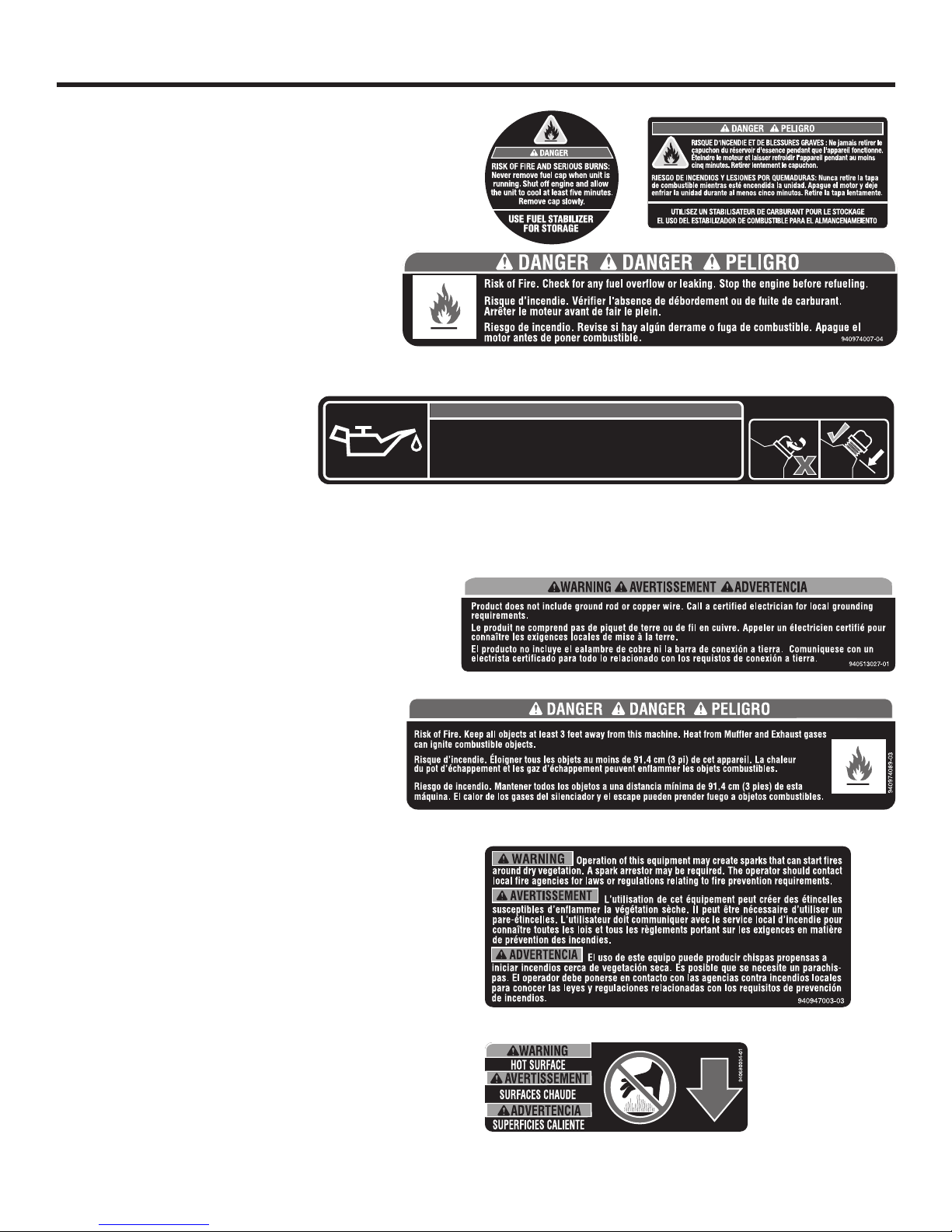
FUEL CAP WARNING
Never remove fuel cap when unit is running. Shut off engine
and allow the unit to cool at least five minutes. Remove cap
slowly to release any pressure built up in the fuel system and
to avoid the heat from the muffler igniting fuel vapors.
FUEL WARNING
No smoking when filling with gasoline. Do not
overfill. Full level is 1 in. below the top of the fuel
neck. Stop the engine for five minutes before
refueling to avoid the heat from the muffler igniting fuel vapors.
ENGINE LUBRICANT WARNING
You must add lubricant before first
operating the generator. Always
check the lubricant level before each
operation. The lubricant level should
940708019-04
Add lubricant to full mark to start. Engine will not start or will shut off if sensor detects
low lubricant level. • Ajouter de lubrifiant jusqu’au repère de remplissage pour
dèmarrer. Le moteur ne démarre pas ou s’éteint si le capteur détecte le niveau de
lubrifiant faible. • Añada lubricante hasta la marca de ileno para arrancar. El motor no
arranca o se apaga si sensor detecta el nivel de lubricante de baja.
always register between the hatched areas on the dipstick. The
unit is equipped with a sensor which will automatically shut off
the engine if the lubricant level falls below a safe limit.
GROUNDING WARNING
This generator does not include a ground rod or copper wire. Call a qualified electrician for local grounding
requirements.
CLEARANCE WARNING
While operating and storing, keep at least 3 feet
of clearance on all sides of this product, including overhead. Allow a minimum of 30 minutes of
“cool down” time before storage. Heat created by
muffler and exhaust gases could be hot enough
to cause serious burns and/or ignite combustible
objects.
NOTICE AVIS AVISO
CHECK LUBRICANT
SPARK ARRESTOR
Operation of this equipment may create sparks that can start
fires around dry vegetation. A spark arrestor may be required.
The operator should contact local fire agencies for laws or
regulations relating to fire prevention requirements.
HOT SURFACE WARNING
Do not touch the muffler or aluminum cylinder of the engine.
They are very HOT and will cause severe burns. Don’t put
body parts or any flammable or combustible materials in the
direct path of the exhaust.
7 — English

ELECTRICAL
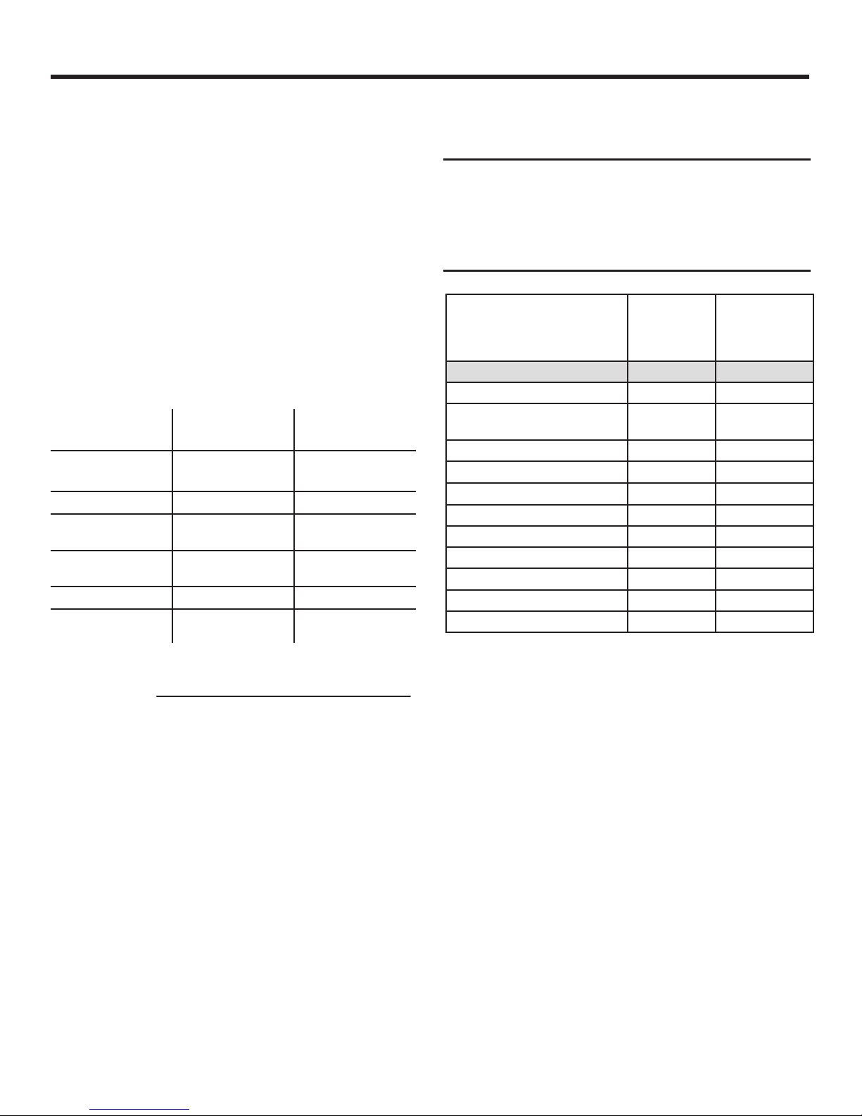
EXTENSION CORD CABLE SIZE
Refer to the table below to ensure the cable size of the extension cords you use are capable of carrying the required load.
Inadequate size cables can cause a voltage drop, which can damage the appliance and overheat the cord.
Current in
Amperes
2.5 300 600 1000 ft. 600 ft. 375 ft. 250 ft.
5 600 1200 500 ft. 300 ft. 200 ft. 125 ft.
7.5 900 1800 350 ft. 200 ft. 125 ft. 100 ft.
10 1200 2400 250 ft. 150 ft. 100 ft. 50 ft.
15 1800 3600 150 ft. 100 ft. 65 ft.
20 2400 4800 175 ft. 125 ft. 75 ft.
25 3000 6000 150 ft. 100 ft.
30 3600 7200 125 ft. 65 ft.
40 4800 9600 90 ft.
Load in Watts Maximum Allowable Cord Length
At 120V At 240V #8 Wire #10 Wire #12 Wire #14 Wire #16 Wire
ELECTRIC MOTOR LOADS
It is characteristic of common electric motors in normal operation to draw up to six times their running current while starting.
This table may be used to estimate the watts required to start electric motors; however, if an electric motor fails to start or
reach running speed, turn off the appliance or tool immediately to avoid equipment damage. Always check the requirements
of the tool or appliance being used compared to the rated output of the generator.
Motor Size (H.P.) Running Watts
1/8 275 N/A 850 1200
1/6 275 600 850 2050
1/4 400 800 1050 2400
1/3 450 950 1350 2700
1/2 600 1000 1800 3600
3/4 850 1200 2600 —
1 1100 N/A 3300 —
Universal Capacitor Split Phase
Watts Required to Start Motor
NOTICE:
Operating voltage and frequency requirement of
all electronic equipment should be checked prior
to plugging them into this generator. Damage may
result if the equipment is not designed to operate
within a +/- 10% voltage variation, and +/- 3 hz
frequency variation from the generator name plate
ratings. To avoid damage, always have an additional
load plugged into the generator if solid state equipment (such as a television set) is used. A power line
conditioner is recommended for some solid state
applications.
GROUND FAULT CIRCUIT INTERRUPTER
See Figure 1.
The 20 amp, 120 volt receptacles on the generator are
protected by a Ground Fault Circuit Interrupter (GFCI),
which guards against the hazards of ground fault currents.
An example of ground fault current is the current that would
flow through a person who is using an appliance with
faulty insulation and, at the same time, is in contact with
an electrical ground such as a plumbing fixture, wet floor,
or earth.
GFCI receptacles do not protect against short circuits,
overloads, or shocks.
The GFCI receptacles can be tested with the TEST and
RESET buttons.
To test:
Depress the TEST button. This should cause the Reset
button to pop out.
To restore power, depress the RESET button.
Perform this test monthly to ensure proper operation of the
GFCI. If the generator is stored outdoors, unprotected from
the weather, test the GFCI receptacle before each use.
8 — English
ELECTRICAL
GENERATOR CAPACITY
Make sure the generator can supply enough continuous (running) and surge (starting) watts for the items you will power
at the same time. Follow these simple steps.
1. Selecttheitemsyouwillpoweratthesametime.
2. Totalthecontinuous(running)wattsoftheseitems.This
is the amount of power the generator must produce to
keep the items running. See the wattage reference chart
at right.
3. Estimatehowmanysurge(starting)wattsyouwillneed.
Surge wattage is the short burst of power needed to
start electric motor-driven tools or appliances such as a
circular saw or refrigerator. Because not all motors start
at the same time, total surge watts can be estimated by
adding only the item(s) with the highest additional surge
watts to the total rated watts from step 2.
Example:
Tool or Appliance
Quartz Work Light
(1000 Watt)
Reciprocating Saw
Drill (1/2 inch,
5.4 amps)
Circular Saw (Heavy
Duty, 7-1/4 in.)
Demolition hammer
Running
Watts*
1000 0
960 960
600 900
1400 2300
600 1200
4560 Total
Running Watts
Starting
Watts*
2300 Highest
Starting Watts
Never add more loads than the generator capacity. Take
special care to consider surge loads in generator capacity
as previously described.
NOTICE:
Do not overload the generator’s capacity. Exceeding the generator’s wattage/amperage capacity may damage the generator and/or electrical
devices connected to it.
Estimated
Tool or Appliance
DIY/Job Site
Quartz Work Light (1000 Watt) 1000 0
Circular Saw (Heavy Duty, 7
1/4”)
Drill (1/2 inch, 5.4 amps) 600 900
Miter Saw (10”) 1800 1800
Battery Charger (15 amp) 380 0
Reciprocating Saw 960 960
Air Compressor (1 HP) 1600 4500
Demolition hammer 1260 1260
Airless Sprayer (1/3 hp) 600 1200
Radio 200 0
Fan (20” Box Fan) 60 200
*Wattages listed are approximate. Check tool or equipment for actual wattage.
Running
Watts*
1400 2300
Estimated
Starting
Watts*
Total Running Watts 4560
Highest Starting Watts + 2300
Total Starting Watts Needed 6860
POWER MANAGEMENT
To prolong the life of the generator and attached devices,
it is important to take care when adding electrical loads to
the generator. There should be nothing connected to the
generator outlets before starting its engine. The correct and
safe way to manage generator power is to sequentially add
loads as follows:
1. With nothing connected to the generator, start the engine
as described later in this manual.
2. Plug in and turn on the first load, preferably the largest
load you have.
3. Permit the generator output to stabilize (engine runs
smoothly and attached device operates properly).
4. Plug in and turn on the next load.
5. Again, permit the generator to stabilize.
6. Repeat steps 4 and 5 for each additional load.
9 — English

FEATURES
PRODUCT SPECIFICATIONS
ENGINE
Engine Type .........................................GX390, 389cc, OHV
Fuel Volume ................................................................ 8 gal.
GENERATOR
Rated Voltage .....................................................120V/240V
Rated Amps ..................................................... 58.3A/29.1A
*Rated running watts determined by PGMA Standard G200
Rated Running Watts* ............................................7,000 W
Rated Starting Watts ..............................................8,750 W
Rated Frequency ........................................................60 Hz
KNOW YOUR GENERATOR
See Figure 2.
The safe use of this product requires an understanding of the
information on the product and in this operator’s manual as
well as a knowledge of the project you are attempting. Before
use of this product, familiarize yourself with all operating
features and safety rules.
AC CIRCUIT BREAKER
The circuit breaker is provided to protect the generator
against electrical overload. The circuit breaker may be reset
by pressing the circuit breaker reset button.
AIR FILTER
The air filter helps to limit the amount of dirt and dust drawn
into the unit during operation.
BATTERY MAINTAINER
Using the battery maintainer when storing the generator
helps keep your generator’s battery charged and ready at
all times.
CHOKE
The choke is used when starting the engine.
ENGINE SWITCH
The engine switch is used alone or in combination with the
recoil starter grip to start the engine. It is also used to turn
the engine off.
GenSmart™ MONITORING SYSTEM
The GenSmart monitoring system tracks usage and load
and alerts the operator when periodic engine maintenance
is needed.
GROUND TERMINAL
The ground terminal is used to assist in properly grounding
the generator to help protect against electrical shock. Consult with a qualified local electrician for grounding requirements in your area.
LOW OIL SHUT DOWN PROTECTOR
The low oil sensor causes the engine to stop if the level of
lubricant in the crankcase is insufficient.
OIL CAP/DIPSTICK
Remove the oil fill cap to check and add lubricant to the
generator when necessary.
OIL DRAIN PLUG
When changing the engine lubricant, the oil drain plug is
removed to allow old engine lubricant to be drained.
RECEPTACLES
The following single phase, 60 Hz outlets on the control panel
can be used for operating appropriate equipment, electrical
lighting, tools, and motor loads: two 120 Volt AC duplex GFCI
20 Amp receptacles and one 240 Volt AC, 30 Amp receptacle.
FUEL TANK
The fuel tank has a capacity of 8 gallons.
FUEL VALVE
Fuel flow from the fuel tank to the engine is turned on and
off using the fuel valve.
RECOIL STARTER GRIP
The recoil starter grip is used (along with the engine switch)
to start the generator’s engine.
10 — English
ASSEMBLY
UNPACKING
This product requires assembly.
Carefully cut the box down the sides then remove the
machine and any accessories from the box. Make sure
that all items listed in the loose parts list are included.
NOTE: This machine is heavy and requires a minimum of
two people to lift. To avoid back injury, lift with your legs
and not your back.
WARNING:
Do not use this product if any parts on the Loose
Parts List are already assembled to your product
when you unpack it. Parts on this list are not
assembled to the product by the manufacturer and
require customer installation. Use of a product that
may have been improperly assembled could result
in serious personal injury.
Inspect the product carefully to make sure no damage
occurred during shipping.
Do not discard the packing material until you have
carefully inspected and satisfactorily operated the
product.
If any parts are damaged or missing, please call
1-866-539-1710, for assistance.
WARNING:
If any parts are damaged or missing do not operate
this product until the parts are replaced. Use of
this product with damaged or missing parts could
result in serious personal injury.
WARNING:
Do not attempt to modify this product or create
accessories not recommended for use with this
product. Any such alteration or modification is
misuse and could result in a hazardous condition
leading to possible serious personal injury.
WARNING:
Do not attempt to operate the generator until
assembly is complete. Failure to comply could
result in possible serious personal injury.
LOOSE PARTS LIST
See Figure 3.
The following items are included with the generator:
Key
No. Description Qty.
1 Axle ......................................................................2
2 Spacer .................................................................2
3 Wheel ...................................................................2
4 Washer (5/8 in.) ....................................................4
5 Hitch Pin ..............................................................2
6 Lock Nut (M6) ......................................................2
7 Legs with Rubber Feet (Left and Right) ...............2
8 Bolt (M6 x 50) ......................................................2
9 Bolt (M5 x12) .......................................................2
10 Flat washer (M5) ..................................................2
11 Lock washer (M5) ................................................2
12 Lock nut (M5) .......................................................2
13 Engine Lubricant..................................................1
14 Battery Maintainer ...............................................1
Operator’s Manual (not shown) ...........................1
TOOLS NEEDED
See Figure 4.
The following tools (not included or drawn to scale) are
needed for assembly:
8 mm and 10 mm Socket Wrench
8 mm and 10 mm Combination Wrench
Philips Screwdriver
NOTE: Do not put fuel or lubricant in the generator before
installing the legs and wheels.
INSTALLING LEGS
See Figure 5.
Locate the following items:
Legs with rubber feet (left and right)
2 lock nuts (M6)
2 bolts (M6 x 50)
Raise the front end of the generator, where the engine is
located, high enough to gain access to the frame bottom;
securely position props underneath to support.
Slide a leg onto the stud on one side of the frame support.
Position the leg so that the holes in the leg align with the
holes in the frame.
Insert bolt through hole in the frame and the leg.
Fasten the bolt by installing a lock nut over bolt on the
inside of the frame. Tighten the nut securely.
Repeat with remaining leg.
11 — English
ASSEMBLY
INSTALLING THE WHEELS
See Figure 6.
Wheels are provided to assist in moving the generator to the
desired location and should be installed on the side opposite
the recoil starter.
Locate the following items:
2 axles
2 spacers
4 washers (5/8 in.)
2 hitch pins
2 wheels
Raise the handle end of the generator
gain access to the frame bottom; securely position props
underneath to support.
Insert the axle bolt through the spacer, then into the
center of the wheel.
Place a washer on the axle bolt, then slide the axle bolt
through the bracket on the frame.
Place a second washer on the axle bolt then i
hitch pin to secure.
NOTE: The hitch pin should be pushed into the axle until
the center of the pin rests on top of the axle.
Repeat the process on the other side to install second
wheel.
high enough to
nstall a
CONNECTING BATTERY
See Figure 7.
WARNING:
To reduce the risk of electrocution or explosion, do
not short circuit the battery terminals or charge in
a sealed container. Keep sparks and flame away.
WARNING:
Keep metal objects away from the battery terminals. Metal objects can make a connection from
one terminal to another. Shorting the battery terminals together could cause sparks, burns, or a fire.
The battery cables must be connected before the electric
start feature of the generator can be operated.
Connect the red wire to the positive (+) terminal first,
thenconnecttheblackwiretothenegative(−)terminal
using the bolts, nuts, and washers provided. Make sure
all connections are tight.
NOTE: Be careful not to short across the terminals when
installing. Shorting the terminals together can cause
sparks, damage to the battery or generator, or even burns
or explosions.
Cover the terminals with the rubber covers.
When removing the battery for replacement: Remove the
nut and bolt first from the negative (black) post, then from
the positive (red) post, being careful not to short across the
terminals. Always abide by the safety warnings provided with
the battery. Remove the battery and dispose of according
to local and state regulations.
CALIFORNIA PROPOSITION 65
WARNING:
This product, its exhaust, and other substances that may become airborne from its use may contain chemicals,
including lead, known to the State of California to cause cancer, birth defects, or other reproductive harm. Wash
hands after handling.
12 — English
OPERATION
DANGER:
Carbon Monoxide. Using a generator indoors CAN
KILL YOU IN MINUTES.
Generator exhaust contains high levels of carbon
monoxide (CO), a poisonous gas you cannot see or
smell. If you can smell the generator exhaust, you
are breathing CO. But even if you cannot smell the
exhaust, you could be breathing CO.
Never use a generator inside homes, garages,
crawlspaces, or other partly enclosed areas.
Deadly levels of carbon monoxide can build up
in these areas. Using a fan or opening windows
and doors does NOT supply enough fresh air.
ONLY use a generator outdoors and far away
from open windows, doors, and vents. These
openings can pull in generator exhaust.
Even when you use a generator correctly, CO may
leak into the home. ALWAYS use a battery-powered
or battery-backup CO alarm in the home.
If you start to feel sick, dizzy, or weak after the generator has been running, move to fresh air RIGHT
AWAY. See a doctor. You could have carbon monoxide poisoning.
WARNING:
If this generator will be used only with cord and
plug-connected equipment, National Electric
Code does not require that the unit be grounded.
However, other methods of using the generator
may require grounding to reduce the risk of shock
or electrocution. Consult a qualified electrician,
electrical inspector, or local agency having jurisdiction for local codes or ordinances to find out if
grounding is needed in your situation before using
the generator.
WARNING:
Do not allow familiarity with this product to make
you careless. Remember that a careless fraction
of a second is sufficient to inflict serious injury.
NOTICE:
This product is equipped with a spark arrestor that
has been evaluated by the USDA Forest Service;
however, product users must comply with Federal,
State, and local fire prevention regulations. Check
with appropriate authorities. Refer to accompanying engine manual for maintenance and replacement parts.
NOTICE:
Before each use, inspect the entire product for
damaged, missing, or loose parts such as screws,
nuts, bolts, caps, etc. Tighten securely all fasteners
and caps and do not operate this product until all
missing or damaged parts are replaced. Please
contact customer service or a qualified service
center for asssistance.
APPLICATIONS
This generator is designed to supply electrical power for
operating compatible electrical lighting, appliances, tools,
and motor loads.
BEFORE OPERATING THE UNIT
Only use OUTSIDE and at least 20 feet away from win-
dows, doors, and vents as recommended by the U.S
Department of Health and Human Services Centers for
Disease Control and Prevention. Your specific home and/
or wind conditions may require additional distance.
NEVER use inside a home or garage, EVEN IF doors and
windows are open.
Always position the generator on a flat, firm surface.
SPECIAL REQUIREMENTS:
There may be General or State Occupational Safety and
Health Administration (OSHA) regulations, local codes or
ordinances that apply to the intended use of the generator.
Please consult a qualified electrician, electrical inspector, or
the local agency having jurisdiction:
In some areas, generators are required to be registered
with local utility companies.
If the generator is used at a construction site, there may
be additional regulations which must be observed.
WARNING:
Do not use any attachments or accessories not
recommended by the manufacturer of this product.
The use of attachments or accessories not recommended can result in serious personal injury.
RAISING AND LOWERING THE HANDLE
See Figure 8.
To raise the handle (for moving the generator): pull the
handle release knob until the handle is up and release
to lock in place. Insert the handle lock pin to secure the
handle in place.
13 — English
OPERATION
To lower the handle (for storing or transporting the gen-
erator): remove the handle lock pin, then pull the handle
release knob out and lower the handle to the down position.
Never use the handle to lift the generator. The handle should
only be used for moving the unit by rolling it on its wheels.
CHECKING/ADDING LUBRICANT
See Figure 9.
NOTICE:
Attempting to start the engine before it has been
properly filled with lubricant will result in equipment
failure.
NOTE: If a separate engine manual is provided for this
product, please follow the instructions provided in the
engine manual instead of the information listed below.
Engine lubricant has a major influence on engine performance
and service life. For general, all-temperature use, SAE
10W-30 is recommended. Always use a 4-stroke motor
lubricant that meets or exceeds the requirements for API
service classification SJ.
This engine comes with a feature that will shut off the engine
when a specific lubricant level is not maintained. The engine
will not restart until an appropriate lubricant level is reached.
NOTE: Non-detergent or 2-stroke engine lubricants will
damage the engine and should not be used.
Unscrew the oil cap/dipstick and remove.
Wipe dipstick clean and re-seat in hole; do not re-thread.
Remove dipstick again and check lubricant level.
Lubricant level should fall between the hatched areas on
the dipstick.
If level is low, add engine lubricant until the fluid level rises
to the upper portion of the dipstick.
Replace and secure the oil cap/dipstick.
USING FUEL STABILIZER
Fuel gets old, oxidizes, and breaks down over time. Adding
a fuel stabilizer (not included) extends the usable life of fuel
and helps prevent deposits from forming that can clog the
fuel system. Follow fuel stabilizer manufacturer’s directions
for correct ratio of stabilizer to fuel.
Mix fuel stabilizer and gasoline prior to filling the tank
by using a gas can or other approved fuel container and
shaking gently to combine.
NOTE: To control the amount of fuel stabilizer being add-
ed to the engine, always mix fuel stabilizer with gasoline
before fueling the tank rather than adding fuel stabilizer
directly into the generator’s fuel tank.
Replace and secure the fuel tank cap.
Start and run the engine for at least 5 minutes to allow
stabilizer to treat the entire fuel system.
ETHANOL-BLENDED FUELS
NOTICE:
Do not use E15 or E85 fuel in this product. It is
a violation of federal law and will damage the
unit and void your warranty. Only use unleaded
gasoline containing up to 10% ethanol.
CHECKING/ADDING FUEL
See Figure 10.
DANGER:
Risk of fire and serious burns: Never remove
fuel cap when unit is running. Shut off engine and
allow the unit to cool at least five minutes. Remove
cap slowly.
WARNING:
Gasoline and its vapors are highly flammable and
explosive. To prevent serious personal injury and
property damage, handle gasoline with care. Keep
away from ignition sources, handle outdoors only,
do not smoke while adding fuel, and wipe up spills
immediately.
When adding gas to the generator, make sure the unit is
sitting on a flat, level surface. If the engine is hot, let the
generator cool for five minutes before adding gas. ALWAYS
fill the fuel tank outdoors with the machine turned off.
Remove the fuel cap slowly.
Fill the fuel tank to 1 in. below the top of the fuel neck.
Replace and secure the fuel cap.
WARNING:
Always shut off engine before fueling. Never
remove fuel cap or add fuel to a machine with a
running or hot engine. Make sure the unit is sitting
on a flat, level surface and only add fuel outdoors.
If the engine is hot, let the unit cool for at least five
minutes before adding fuel. After fueling, immediately replace fuel cap and tighten securely. Move
at least 30 ft. from refueling site before starting
engine. Do not smoke and stay away from open
flames and sparks! Failure to follow these instructions could result in a fire and cause serious personal injury.
NOTE: Always use unleaded gasoline with a pump octane
rating of 86 or higher. Never use old, stale, or contaminated
gasoline, and do not use an oil/gas mixture. Do not allow dirt
or water into the fuel tank. Do not use E85 fuel.
14 — English
OPERATION
GenSmart™ MONITORING SYSTEM
See Figure 11.
The GenSmart™ monitoring system displays wattage, voltage, hertz, and hours. To cycle through each display, press
and release the select/reset button.
Load Indicator
Measures the wattage output of the 2 x 120 Volt duplex GFCI
and 1 x 240 Volt, 30 Amp outlets located on the control panel.
Hour Meter
The digital hour meter operates whenever the engine is running and keeps track of how many hours the unit has been
used. Use this meter along with the accompanying engine
manual to determine when and what type of service on the
unit is needed. To display, press and release the select/reset
button to cycle through the displays until HRS appears.
Maintenance Warning System
At every 100 hours of use, the GenSmart™ monitoring system will display a flashing message informing the operator
to service the engine as required by the engine operator’s
manual. To reset this message, push and hold the select/
reset button located underneath the GenSmart™ display for
5 seconds.
NOTE: Be careful to only press and hold the reset button
when you want the maintenance panel to be reset.
ELECTRIC START
This generator model is provided with both electric start and
recoil start capabilities. Avoid prolonged cranking, as it can
damage the engine.
The battery provided is a nominal 12 volt sealed rechargeable lead-acid battery and can be operated in any position
without leakage. It complies with non-spillable battery
regulations. Its convenient size offers a 30% reduction over
conventional batteries.
NOTE: Brand new generators are shipped with the battery
connections disconnected. The positive and negative terminals must be connected to the battery before the Electric
Start feature will work.
For initial battery connection, see Connecting Battery.
STARTING THE ENGINE
See Figures 12 - 15.
NOTICE:
On a level surface with the engine off, check the
lubricant level before each use of the generator.
NOTE: If location of generator is not level, the unit may not
start or may shut down during operation.
Unplug all loads from the generator.
Turn the fuel valve to the ON ( I ) position.
Pull the choke lever out to the start position.
NOTE: If engine is warm or the temperature is above
50˚F,pushthechokeleverintotheRUN position.
Start the engine.
1
Put the engine switch in the ON position.
2
Slide down and hold the lock button while pushing
the engine switch to the START position.
NOTE: The battery may require charging before the gen-
erator can be started using only the engine switch. The
generator can be started by pulling the recoil starter grip.
Once the generator is started, the battery will charge as
the unit runs. To start the engine using the recoil starter:
1
Put the engine switch in the ON position.
2 Pull the recoil starter grip until the engine runs.
NOTE: Do not allow the grip to snap back after start-
ing; return it gently to its original place.
Allow the engine to run for 15 – 30 seconds, then push
the choke lever to the RUN position.
STOPPING THE ENGINE
See Figures 12 - 14.
Remove any load from the generator.
Turn the fuel valve to the OFF ( O ) position.
To stop the engine, push in at the bottom of the switch
to place the engine switch in the OFF ( O ) position.
WARNING:
While operating and storing, keep at least 3 feet
of clearance on all sides of this product, including
overhead. Allow a minimum of 30 minutes of “cool
down” time before storage. Heat created by muffler
and exhaust gases could be hot enough to cause
serious burns and/or ignite combustible objects.
15 — English
 Loading...