

RIDGID RD906812A, RD906812B Operator's Manual
To register your RIDGID
product, please visit:
http://register.RIDGID.com
Pour enregistrer votre
produit de RIDGID,
s’il vous plaît la visite:
http://register.RIDGID.com
Para registrar su producto
de RIDGID, por favor visita:
http://register.RIDGID.com
OPERATOR’S MANUAL
Manuel de l’opérateur
Manual del operador
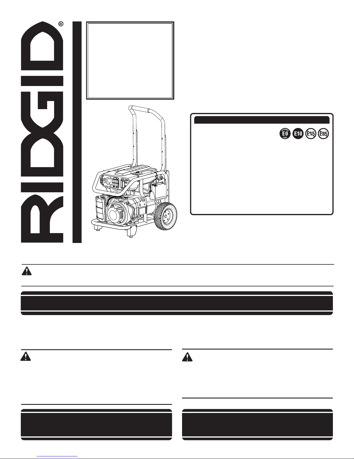
PORTABLE GENERATOR
Générateur portable
Generador portàtil
RD906812A/RD906812B
NOTICE AVIS AVISO
Do not use E15 or E85 fuel (or
fuel containing greater than 10%
ethanol) in this product. It is a
violation of federal law and will damage the unit and
void your warranty.
Ne pas utiliser d’essence E15 ou E85 (ou un carburant
contenant plus de 10 % d’éthanol) dans ce produit. Une
telle utilisation représente une violation de la loi fédérale
et endommagera l’appareil et annulera la garantie.
No utilice combustibles E15 o E85 (ni combustibles que
contengan más de 10 % de etanol) con este producto.
Esto constituye una violación a la ley federal, dañará la
unidad y anulará la garantía.
NEUTRAL BONDED TO FRAME
(CONNECTEUR NEUTRE RELIÉ AU CADRE, PUNTO
NEUTRO CONECTADO AL MARCO)
Your generator has been engineered and manufactured to our high standard for dependability, ease of operation, and operator
safety. When properly cared for, it will give you years of rugged, trouble-free performance.
WARNING: To reduce the risk of injury, the user must read and understand the operator’s manual before using this
product. If you do not understand the warnings and instructions in the operator’s manual, do not use this product.
SAVE THIS MANUAL FOR FUTURE REFERENCE
Ce générateur a été conçu et fabriqué conformément à nos strictes
normes de fiabilité, simplicité d’emploi et sécurité d’utilisation.
Correctement entretenu, cet outil vous donnera des années de
fonctionnement robuste et sans problème.
AVERTISSEMENT :
Pour réduire les risques de blessures, l’utilisateur doit
lire et veiller à bien comprendre le manuel d’utilisation
avant d’employer ce produit. Si tous les avertissements
et toutes les consignes de sécurités et instructions du
manuel d’utilisation ne sont pas bien compris, ne pas
utiliser ce produit.
Su generador diseñado y fabricado de conformidad con nuestras
estrictas normas para brindar fiabilidad, facilidad de uso y seguridad para el operador. Con el debido cuidado, le brindará muchos
años de sólido funcionamiento y sin problemas.
ADVERTENCIA:
Para reducir el riesgo de lesiones, el usuario debe leer y
comprender el manual del operador antes de usar este
producto. Guarde este manual del operador y estúdielo
frecuentemente para lograr un funcionamiento seguro y
continuo de este producto.
CONSERVER CE MANUEL POUR
FUTURE RÉFÉRENCE
GUARDE ESTE MANUAL PARA
FUTURAS CONSULTAS

See this fold-out section for all of the figures
referenced in the operator’s manual.
Consulter l’encart à volets afin d’examiner toutes les
figures mentionnées dans le manuel d’utilisation.
Consulte esta sección desplegable
para ver todas las figuras a las que se
hace referencia en el manual del operador.
ii
ENGINE SWITCH
OFF
CIRCUIT BREAKER
OFF
PRESS
AND
HOLD
ENGINE SWITCH
NEUTRAL BONDED
TO FRAME
HRS
MAINTENANCE
Hz
A
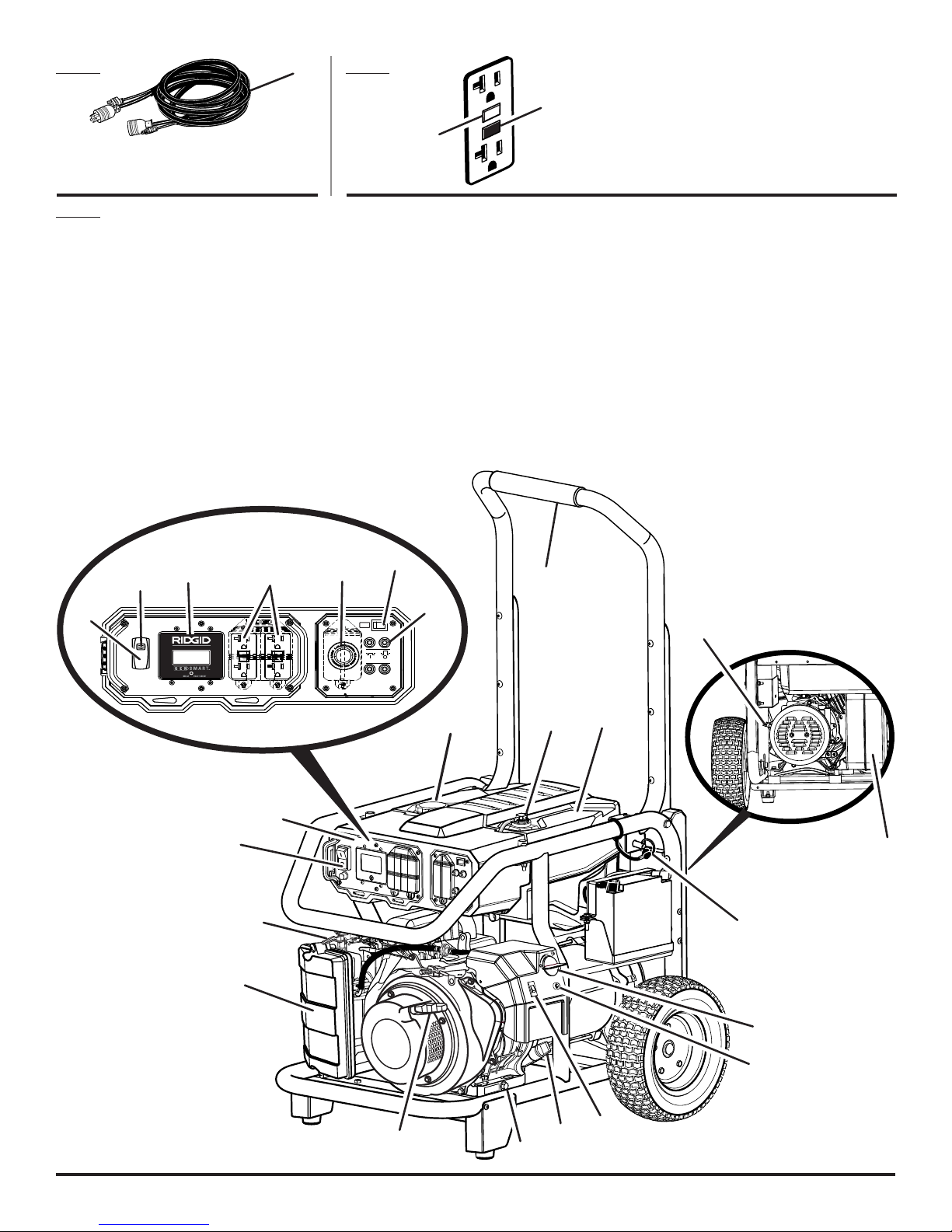
A - Control panel cord (not provided) [cordon
de panneau de commande (non fourni),
cordón de panel de control (no incluido)]
Fig. 3
A - Recoil starter grip (poignée du démarreur à
rappel, mango del arrancador retráctil)
B - Air filter (filtre à air, filtro de aire)
C - Choke lever (levier d’étrangleur, palanca del
anegador)
D - Removable control panel (panneau de
commande amovible, panel de control en
distintas)
E - Fuel cap (bouchon de carburant, tapa del
tanque)
F - Engine switch (commutateur du moteur,
interruptor del motor)
G - GenSmart™ monitoring system (système
de surveillance GenSmart™, sistema de
monitoreo GenSmart™)
H - 120 volt AC GFCI 20 amp receptacles (prises
120 V C.A. GFCI 20 A, 120 V de CA GFCI 20
A receptáculos)
Fig. 2Fig. 1
B
A
I - 240 V AC 30 amp receptacle (prise 240 V C.A.
30 A, 240 V de CA 30 A receptáculo)
J - AC circuit breaker (disjoncteur de C.A.,
disyuntor de circuito de CA)
K - Handle (poignée, mango)
L- Fuel tank (réservoir de carburant, tanque de
combustible)
M
- Fuel tank vapor vent (évent de vapeur du
réservoir de carburant, respirador del vapor
del tanque de combustible)
N
- Ground terminal (borne de terre, terminal de
conexión a tierra)
O - Oil cap/dipstick (bouchon/jauge d’huile,
tapa de relleno de aceite/varilla medidora de
aceite)
A - Reset button (bouton de réinitialisation,
botón de reajuste)
B - Test button (bouton de test, botón de
prueba)
P - Oil drain plug (huiler le bouchon d’égout,
tapón de drenaje del aceite)
Q - Handle lock pin (goupille de blocage de la
poignée, pasador de seguro del mango)
R - Fuel valve (robinet de carburant, válvula de
combustible)
S - Muffler (silencieux, silenciador)
T
- Lock button (bouton de verrouillage, botón
del seguro)
U - Idle control switch (commande du ralenti,
interruptor de control de ralentí)
V - Low oil shut-off indicator (indicateur de bas
niveau d’huile, indicador de apagado por
poco aceite)
T
G
H
I
F
F
K
J
N
E
M
L
D
F
C
Q
S
B
R
V
U
A
O
P
iii
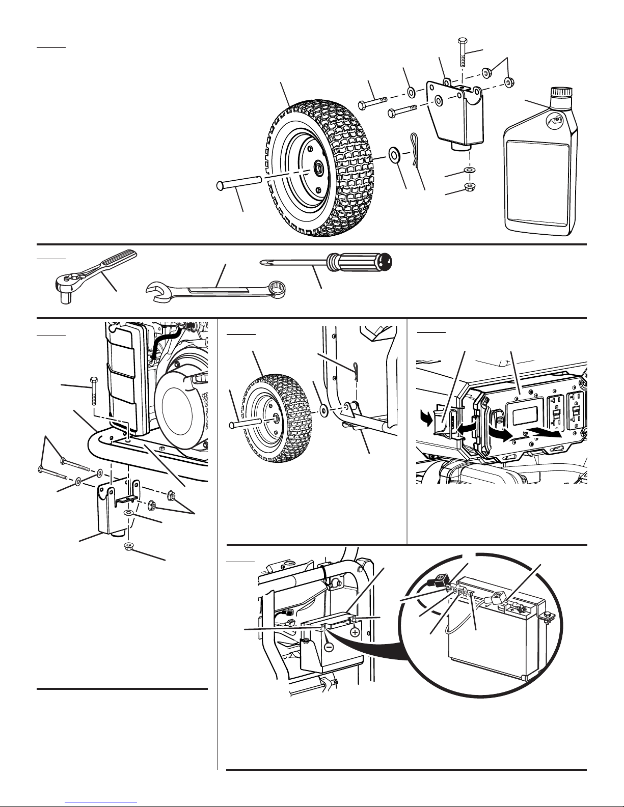
Fig. 4
1 - Axle (essieu, eje)
2 - Wheel (roue, rueda)
3 - Washer (rondelle, arandela)
4 - Hitch pin (axe de blocage, pasador del
enganche)
5 - Screw, 2 in. (vis, 2 po; tornillo, 2 pulg.)
6 - Washer (rondelle, arandela)
7 - Leg with rubber foot (pied avec patin en
caoutchouc, pata con pie de goma)
8 - Nut (écrou, tuerca)
9 - Screw, 1 in. (vis, 1 po; tornillo, 1 pulg.)
10 - Engine lubricant (lubrifiant de moteur,
lubricante para motor)
7
6
2
1
5
6
4
3
8
9
8
10
Fig. 5
Fig. 6
F
A
B
B
A
C
Fig. 7
B
A
E
C
A - Socket wrench (clé à douille, llave de
casquillo)
B - Combination wrench (clé mixte, llave de
combinación)
C - Phillips screwdriver (tournevis phillips,
destornillador phillips)
Fig. 9
A
B
E
D
A - Axle (essieu, eje)
G
B
D
C
B - Wheel (roue, rueda)
C - Washer (rondelle, arandela)
D - Mount bracket (support de montage, soporte
C
de montaje)
E - Hitch pin (goupille de sûreté, pasador de
enganche)
Fig. 8
A - Latch (loquet, pestillo)
B - Removable control panel (panneau de
commande amovible, panel de control en
distintas)
A
D
H
A - Screw, 2 in. (vis, 2 po; tornillo, 2 pulg.)
B - Washer (rondelle, arandela)
C - Lock nut (écrou de blocage, tuerca de
seguridad)
D - Leg with rubber foot (pied avec patin en
caoutchouc, pata con pie de goma)
E - Frame (cadre, armazón)
F - Screw, 1 in. (vis, 1 po; tornillo, 1 pulg.)
G - Frame crossbar (barre stabilisatrice du cadre
travesaño del bastidor)
E
B
C
A - Battery bracket (support de pile, soporte de la
batería)
B - Positive (+) terminal [borne positive (+), tapa
del terminal positiva (+)]
C - Negative (–) terminal [borne négative (–),
terminal negativa (–)]
iv
F
C
D - Black wire (–) [fil noir (–), cable negro (–)]
E - Screw (vis, tornillo)
F - Washer (rondelle, arandela)
G - Nut (écrou tuerca)
H - Red wire (+) [fil rouge (+), cable rojo (+)]
G
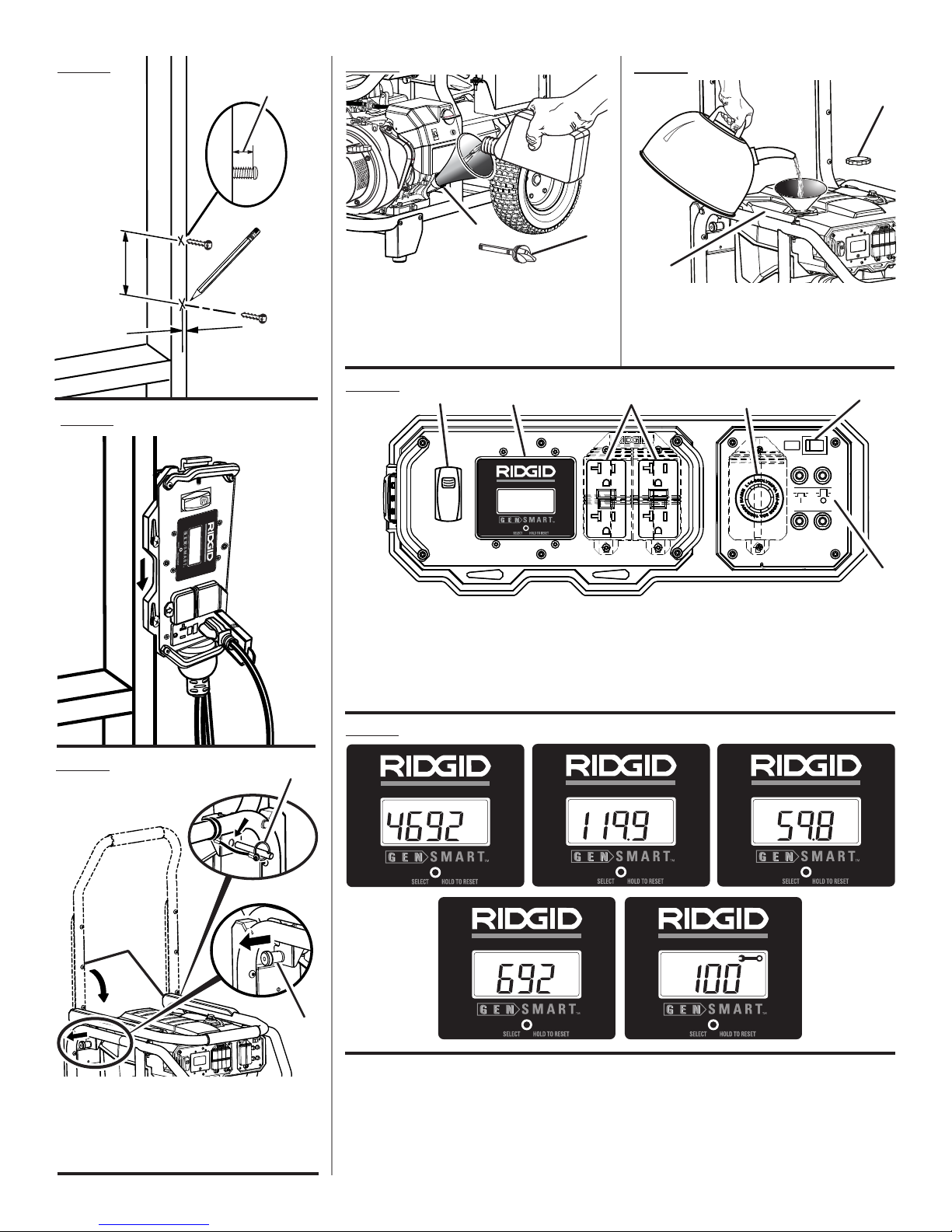
4-1/4 in.
(po, pulg.)
5/8 in.
(po, pulg.)
1/4 in.
(po, pulg.)
Fig. 10
Fig. 13
Fig. 14
A
Fig. 11
B
A
B
A - Oil cap/dipstick (bouchon/ jauge d’huile,
tapa de relleno de aceite/varilla medidora de
aceite)
B - Oil fill hole (orifice de remplissage d’huile,
agujero de llenado de aceite)
Fig. 15
MAINTENANCE
Hz
HRS
A
ENGINE SWITCH
OFF
PRESS AND
HOLD
NEUTRAL BONDED
TO FRAME
B
MAINTENANCE
Hz
HRS
A - Fuel cap (bouchon de carburant, tapa del
tanque de combustible)
B - Fuel tank (réservoir de carburant, tanque de
combustible)
C
D
OFF
ENGINE SWITCH
CIRCUIT BREAKER
A
E
A - Engine switch (commutateur du moteur,
interruptor del motor)
B - GenSmart™ monitoring system (système
de surveillance GenSmart™, sistema de
monitoreo GenSmart™)
C - 120 volt AC 20 amp receptacles (prises 120 V
C.A. 20 A, 120 V de CA 20 A receptáculos)
D - 240 volt AC 30 amp receptacle (prise 240 V
C.A. 30 A, 240 V de CA 30 A receptáculo)
E - AC circuit breaker (disjoncteur de C.A.,
disyuntor de circuito de CA)
Fig. 12
C
A
B
A - Handle (poignée, mango)
B - Handle release knob (relâchez le bouton de
poignée, perilla de afloje del mango)
C - Handle lock pin (goupille de blocage de la
poignée, pasador de seguro del mango)
Fig. 16
MAINTENANCE
Hz
W
HRS
MAINTENANCE
v
MAINTENANCE
Hz
W
HRS
Hz
W
HRS
MAINTENANCE
MAINTENANCE
Hz
W
HRS
Hz
W
HRS

Fig. 17
A
Fig. 19
A - Handle lock pin
(goupille de blocage
de la poignée,
pasador de seguro
del mango)
B - Joined area (partie
jointe, área acoplada)
B
A
B
C
B
A
E
A - Control panel cord (not provided) [cordon
de panneau de commande (non fourni),
cordón de panel de control (no incluido)]
B - Twist-lock plug (prise à verrouillage, enchufe
de bloqueo de giro)
C - Twist-lock receptacle (prise à verrouillage par
rotation, receptáculo de fijación)
D - 12 Volt DC connector (connecteur de 12 V
c.c., conector de corr. cont. de 12 V)
E - 12 Volt DC receptacle (prise de 12 V c.c.,
receptáculo de corr. cont. de 12 V)
D
Fig. 18
Fig. 20
Fig. 21
TECHNOLOGY
I
J
A
CB
H
D
F
A - Fuel valve (robinet de carburant, válvula de combustible)
B - Off (arret, apagado)
C - On (marche, encendido)
D - Choke lever (levier de volet de départ, palanca del anegador)
E - Start position (position de démarrage, posición de arranque)
F - Run position (position de marche, posición de functionamiento)
G - Recoil starter grip (manchon en lanceur à rappel, agarradera del arranque retráctil)
H - Idle control switch (commande du ralenti, interruptor de control de ralentí)
I - (I) On (marche, encendido)
J - (O) Off (arret, apagado)
E
vi
G
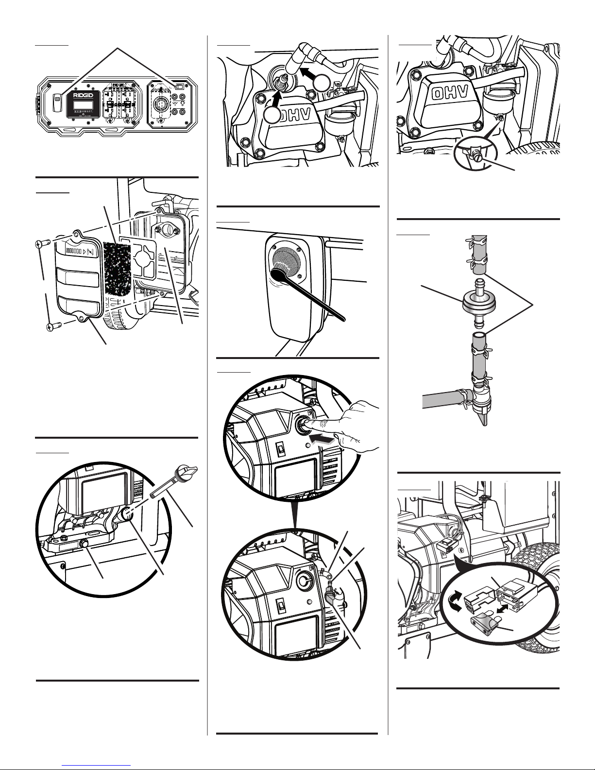
Fig. 22
A
Fig. 25
Fig. 28
ENGINE SWITCH
OFF
PRESS AND
HOLD
NEUTRAL BONDED
TO FRAME
MAINTENANCE
Hz
HRS
OFF
ENGINE SWITCH
CIRCUIT BREAKER
A - Engine switch (commutateur du moteur,
interruptor encendido/apagado del motor)
Fig. 23
C
A
D
B
A - Screws (vis, tornillos)
B - Air filter cover (couvercle du filtre à air, tapa del
filtro de aire)
C - Filter element (élément du filtre, elemento
de filtro)
D - Air filter unit (unité de filtre à air, unidad del
filtro de aire)
Fig. 24
B
A
A - Spark plug (bougie, bujía)
B - Spark plug cap (capuchon de bougie, tapa de
la bujía)
Fig. 26
Fig. 27
A
A - Carburetor drain screw (vis de vidange
du carburateur, tornillo de drenaje del
carburador)
Fig. 29
B
A
OFF
A - Fuel line (conduites de carburant ,conducto
de combustible)
B - Fuel filter (filtre à carburant, filtro de
combustible)
A
C
A - Oil cap/dipstick (bouchon/ jauge d’huile,
tapa de relleno de aceite/varilla medidora de
aceite)
B - Oil fill hole (orifice de remplissage d’huile,
agujero de llenado de aceite)
C - Oil drain plug (huiler le bouchon d’égout,
tapón de drenaje del aceite)
B
A
B
C
A - Fuel line (conduite de carburant, conducto de
combustible)
B - Petcock (robinet de carburant, llave de
purga)
C - Fuel valve (robinet de carburant, válvula de
combustible)
vii
Fig. 30
A
B
A - Cover (couvercle, cubierta)
B - Fuse (fusible, fusible)
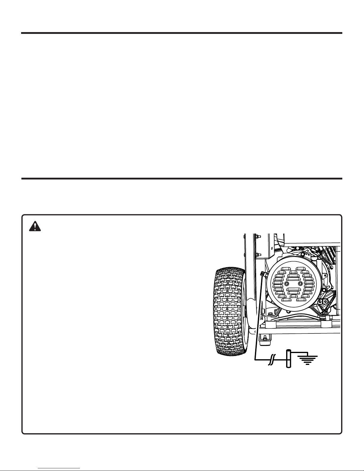
TABLE OF CONTENTS
Introduction ..................................................................................................................................................................... 2
Important Safety Instructions ....................................................................................................................................... 3-4
Specific Safety Rules ...................................................................................................................................................... 4
Symbols .......................................................................................................................................................................5-7
Electrical ....................................................................................................................................................................... 7-9
Features ...................................................................................................................................................................10-11
Assembly .................................................................................................................................................................. 11-12
Operation .................................................................................................................................................................. 13-16
Maintenance ............................................................................................................................................................. 17-20
Troubleshooting ............................................................................................................................................................. 21
Warranty ...................................................................................................................................................................22-25
Parts Ordering / Service ...................................................................................................................................Back Page
INTRODUCTION
This product has many features for making its use more pleasant and enjoyable. Safety, performance, and dependability
have been given top priority in the design of this product, making it easy to maintain and operate.
DANGER:
GROUNDING THE GENERATOR
To reduce the risk of shock or electrocution, generator must be
properly grounded. The nut and ground terminal on the frame
must always be used to connect the generator to a suitable
ground source. The ground path should be made with #8 size
wire. Connect the terminal of the ground wire between the lock
washer and the nut, and tighten the nut fully. Connect the other
end of the wire securely to a suitable ground source.
The National Electric Code contains several practical ways in
which to establish a good ground source. If a steel or iron rod is
used, it should be at least 5/8 in. diameter, and if a nonferrous
rod is used, it should be at least 1/2 in. diameter and be listed as
material for grounding. Drive the rod or pipe to a depth of 8 ft. If
a rock bottom is encountered less than 4 ft. down, bury the rod
or pipe in a trench.
All electrical tools and appliances operated from this generator
must be properly grounded by use of a third wire or be “Double
Insulated.”
It is recommended to:
1. Use electrical devices with 3-prong grounded plugs.
2. Use an extension cord intended for outdoor use with a 3-pole receptacle and a 3-prong plug at opposite ends to
ensure continuity of the ground protection from the generator to the appliance.
Check and adhere to all applicable federal, state, and local regulations relating to grounding specifications. Consult a
qualified electrician or service personnel if the grounding instructions are not completely understood or if in doubt as
to whether the generator is properly grounded.
2 — English

IMPORTANT SAFETY INSTRUCTIONS
Do not start or operate the engine in a confined space,
DANGER:
Carbon Monoxide. Using a generator indoors CAN
KILL YOU IN MINUTES.
Generator exhaust contains high levels of carbon
monoxide (CO), a poisonous gas you cannot see or
smell. If you can smell the generator exhaust, you
are breathing CO. But even if you cannot smell the
exhaust, you could be breathing CO.
Never use a generator inside homes, garages,
crawlspaces, or other partly enclosed areas.
Deadly levels of carbon monoxide can build up
in these areas. Using a fan or opening windows
and doors does NOT supply enough fresh air.
ONLY use a generator outdoors and far away
from open windows, doors, and vents. These
openings can pull in generator exhaust.
Even when you use a generator correctly, CO may
leak into the home. ALWAYS use a battery-powered
or battery-backup CO alarm in the home.
If you start to feel sick, dizzy, or weak after the
generator has been running, move to fresh air
RIGHT AWAY. See a doctor. You could have carbon
monoxide poisoning.
WARNING:
Read and understand all instructions. Failure to
follow all instructions listed below could result
in electrocution, fire, and/or carbon monoxide
poisoning, which can cause death or serious injury.
DANGER:
National Electric Code requires generator to be
grounded to an approved earth ground. Before
using the ground terminal, consult a qualified
electrician, electrical inspector, or local agency
having jurisdiction for local codes or ordinances
that apply to the intended use of the generator.
SAVE THESE INSTRUCTIONS
This manual contains important instructions for this product
that should be followed during installation and maintenance
of the generator.
Do not connect to a building’s electrical system unless
the generator and transfer switch have been properly
installed and the electrical output has been verified by
a qualified electrician. The connection must isolate the
generator power from utility power and must comply with
all applicable laws and electrical codes.
Do not allow children or untrained individuals to use this
unit.
building, near open windows, or in other unventilated
space where dangerous carbon monoxide fumes can
collect. Carbon monoxide, a colorless, odorless, and
extremely dangerous gas, can cause unconsciousness
or death.
Keep all bystanders, children, and pets at least 10 feet
away.
Wear sturdy and dry shoes or boots. Do not operate while
barefoot.
Do not operate generator when you are tired or under the
influence of drugs, alcohol, or medication.
Keep all parts of your body away from any moving parts
and all hot surfaces of the unit.
Do not touch bare wire or receptacles.
Do not use generator with electrical cords which are worn,
frayed, bare, or otherwise damaged.
Before storing, allow the engine to cool and drain fuel
from the unit.
Do not operate or store the generator in rain, snow, or
wet weather.
Store the generator in a well-ventilated area with the fuel
tank empty. Fuel should not be stored near the generator.
Empty fuel tank, close fuel valve, and restrain the unit
from moving before transporting in a vehicle.
Allow engine to cool for five minutes before refueling.
To reduce the risk of fire and burn injury, handle fuel with
care. It is highly flammable.
Do not smoke while handling fuel.
Store fuel in a container approved for gasoline.
Position the unit on level ground, stop engine, and allow
to cool before refueling.
Loosen fuel cap slowly to release pressure and to keep
fuel from escaping around the cap.
Tighten the fuel cap securely after refueling.
Wipe spilled fuel from the unit.
Never attempt to burn off spilled fuel under any circum-
stances.
Generators vibrate in normal use. During and after the
use of the generator, inspect the generator as well as
extension cords and power supply cords connected to
it for damage resulting from vibration. Have damaged
items repaired or replaced as necessary. Do not use plugs
or cords that show signs of damage such as broken or
cracked insulation or damaged blades.
For power outages, permanently installed stationary gen-
erators are better suited for providing back-up power to
the home. Even a properly connected portable generator
can become overloaded. This may result in overheating
or stressing the generator components, possibly leading
to generator failure.
3 — English

IMPORTANT SAFETY INSTRUCTIONS
Use only authorized replacement parts and accessories
and follow instructions in the Maintenance section of this
manual. Use of unauthorized parts or failure to follow
maintenance instructions may create a risk of shock or
injury.
SPECIFIC SAFETY RULES
WARNING:
When this generator is used to supply a building
wiring system: generator must be installed
by a qualified electrician and connected to a
transfer switch as a separately derived system
in accordance with NFPA 70, National Electrical
Code. The generator shall be connected through a
transfer switch that switches all conductors other
than the equipment grounding conductor. The
frame of the generator shall be connected to an
approved grounding electrode. Failure to isolate
the generator from power utility can result in death
or injury to electric utility workers.
Do not use this generator to provide power for emergency
medical equipment or life support devices.
This generator has a neutral bonded condition. This
means the neutral conductor is electrically connected to
the frame of the machine.
Exhaust contains poisonous carbon monoxide, a color-
less, odorless gas. Breathing exhaust can cause loss
of consciousness and can lead to death. If running in a
confined or partially-enclosed area, the air may contain a
dangerous amount of carbon monoxide. To keep exhaust
fumes from building up, always provide adequate ventilation.
Always use a battery-powered carbon monoxide detec-
tor when running the generator. If you begin to feel sick,
dizzy, or weak while using the generator, shut it off and
get to fresh air immediately. See a doctor. You may have
carbon monoxide poisoning.
Place the generator on a flat, stable surface with a slope
of no more than 4°.
Operate outdoors in a well-ventilated, well-lit area isolated
from working areas to avoid noise interference.
Operating the generator in wet conditions could result in
electrocution. Keep the unit dry.
Keep the generator a minimum of 3 feet away from all
types of combustible material.
Do not operate generator near hazardous material.
Do not operate generator at a gas or natural gas filling
station.
Maintain the unit per maintenance instructions in this
Operator’s Manual.
Inspect the unit before each use for loose fasteners, fuel
leaks, etc. Replace damaged parts.
Do not touch the muffler or cylinder during or immediately
after use; they are HOT and will cause burn injury.
This generator has a neutral bonded condition. This
means the system ground is connected electrically to
the AC neutral wire.
Do not allow the generator’s gas tank to overflow when
filling. Fill to 1 in. below the top neck of the gasoline tank
to allow for fuel expansion. Do not cover the fuel tank cap
when the engine is running. Covering the fuel tank cap
during use may cause engine failure and/or damage to
the tool.
Do not smoke when filling the generator with gasoline.
Shut down the engine and allow to cool completely before
adding gasoline or lubricant to the generator.
Do not remove the oil dipstick or the fuel tank cap when
the engine is running.
Pay close attention to all safety labels located on the
generator.
Keep children a minimum of 10 feet away from the gen-
erator at all times.
The unit operates best in temperatures between 23°F and
104°F with a relative humidity of 90% or less.
Operating voltage and frequency requirement of all
electronic equipment should be checked prior to plugging them into this generator. Damage may result if the
equipment is not designed to operate within a +/- 10%
voltage variation, and +/- 3 hz frequency variation from
the generator name plate ratings. To reduce the risk of
damage, always have an additional load plugged into the
generator if solid state equipment (such as a television
set) is used. A power line conditioner is recommended
for some solid state applications.
When battery is not in use, keep it away from other metal
objects like paper clips, coins, keys, nails, screws, or other
small metal objects that can make a connection from
one terminal to another. Shorting the battery terminals
together may cause burns or a fire.
For outdoor use only.
Save these instructions. Refer to them frequently and use
them to instruct others who may use this product. If you
loan someone this product, loan them these instructions
also.
4 — English
 Loading...